JP5089360B2 - Inkjet recording device - Google Patents
Inkjet recording device Download PDFInfo
- Publication number
- JP5089360B2 JP5089360B2 JP2007317229A JP2007317229A JP5089360B2 JP 5089360 B2 JP5089360 B2 JP 5089360B2 JP 2007317229 A JP2007317229 A JP 2007317229A JP 2007317229 A JP2007317229 A JP 2007317229A JP 5089360 B2 JP5089360 B2 JP 5089360B2
- Authority
- JP
- Japan
- Prior art keywords
- recording
- ink
- head
- recording element
- ink jet
- Prior art date
- Legal status (The legal status is an assumption and is not a legal conclusion. Google has not performed a legal analysis and makes no representation as to the accuracy of the status listed.)
- Expired - Fee Related
Links
Images


Landscapes
- Ink Jet (AREA)
- Particle Formation And Scattering Control In Inkjet Printers (AREA)
Description
本発明は、インクを吐出する記録素子を配列して構成されるインクジェット記録ヘッドを用い、記録媒体に画像を記録するインクジェット記録装置に関する。特に複数の記録素子のうちの幾つかに吐出不良が生じた場合であっても、出力画像にドットの欠落や白すじが生じないようにするための記録ヘッド構成および記録方法に関する。 The present invention relates to an ink jet recording apparatus that records an image on a recording medium using an ink jet recording head configured by arranging recording elements that eject ink. In particular, the present invention relates to a recording head configuration and a recording method for preventing missing dots or white streaks in an output image even when ejection failure occurs in some of a plurality of recording elements.
従来、インクジェット記録装置は、ランニングコストが安く、装置の小型化も可能で、さらに比較的簡易な構成で複数色のインクを用いたカラー画像の記録も可能であることから、コンピュータ関係の出力機器等に広く有用されている。インクジェット記録ヘッドの吐出口からインクを吐出するためのエネルギ発生手段としては、ピエゾ素子などの電気機械変換体、レーザーなどの電磁波を照射して発熱させるもの、あるいは、発熱抵抗体を備えた電気熱変換素子等が挙げられる。中でも電気熱変換素子から得られる熱エネルギを利用してインク滴を吐出させるインクジェット記録ヘッドは、吐出口を高密度に配列することができるため、小型でありながら高解像な実現することが出来る。更に、半導体分野やフォトリソ技術における進歩と信頼性の向上とが相俟って、近年では高性能な記録ヘッドを低価格に提供することが可能になって来ている。 Conventional inkjet recording apparatuses have low running costs, can be downsized, and can record color images using a plurality of colors of ink with a relatively simple configuration. Etc. are widely useful. The energy generating means for discharging ink from the discharge port of the ink jet recording head includes an electromechanical transducer such as a piezo element, a device that generates heat by irradiating an electromagnetic wave such as a laser, or an electric heat provided with a heating resistor. A conversion element etc. are mentioned. In particular, an ink jet recording head that ejects ink droplets using thermal energy obtained from an electrothermal conversion element can arrange discharge ports at high density, and thus can be realized in a small size but with high resolution. . Furthermore, in combination with progress in the semiconductor field and photolithography technology and improvement in reliability, in recent years it has become possible to provide a high-performance recording head at a low price.
このように高精細な記録が可能な電気熱変換素子を備えたインクジェット記録ヘッドでは、より高速に画像を出力するために多数の記録素子を配置する記録ヘッドの長尺化が進められている。具体的には、例えば1200dpi(ドット/インチ;参考値)程度の密度で記録素子が配列した、4インチ〜13インチの長さを有する記録ヘッドが提供されている。 In such an ink jet recording head provided with an electrothermal conversion element capable of high-definition recording, the length of the recording head in which a large number of recording elements are arranged in order to output an image at a higher speed is being promoted. Specifically, a recording head having a length of 4 inches to 13 inches in which recording elements are arranged at a density of about 1200 dpi (dot / inch; reference value) is provided.
このような長尺な記録ヘッドで、記録媒体の幅に相当する長さを有する記録ヘッドを用いれば、フルライン型の記録装置を実現することが可能となる。本明細書においてフルライン型の記録装置とは、記録装置に固定された記録ヘッドの個々の記録素子から所定の周波数でインクを吐出し、その一方で記録素子の配列方向とは交差する方向に記録媒体を搬送することにより画像を記録する記録装置のことを示す。また、記録ヘッドを記録媒体に対し走査させながら記録を行う主記録走査と、当該主記録走査とは交差する方向に記録媒体を所定量ずつ搬送することにより間欠的に画像を記録していく記録装置を、本明細書ではシリアル型の記録装置と称する。記録装置を記録媒体の幅に対応する数だけ備えたフルライン型の記録装置であれば、記録媒体の1回の走査により記録媒体全体への記録が完了するので、シリアル型の記録装置に比べ、短い時間で画像を出力することが可能となる。また、シリアル型であっても、記録ヘッドが長尺であるほど、記録主走査の回数を抑え、より短時間で画像を出力することが出来る。 If such a long recording head having a length corresponding to the width of the recording medium is used, a full-line type recording apparatus can be realized. In this specification, the full-line type recording apparatus means that ink is ejected from each recording element of a recording head fixed to the recording apparatus at a predetermined frequency, while in a direction crossing the arrangement direction of the recording elements. A recording apparatus that records an image by conveying a recording medium is shown. Also, a main recording scan for recording while the recording head scans the recording medium, and a recording in which an image is recorded intermittently by conveying the recording medium by a predetermined amount in a direction crossing the main recording scan. The apparatus is referred to as a serial type recording apparatus in this specification. In the case of a full-line type recording apparatus provided with the number of recording apparatuses corresponding to the width of the recording medium, the recording on the entire recording medium is completed by one scanning of the recording medium. It is possible to output an image in a short time. Even in the case of the serial type, the longer the recording head is, the more the number of recording main scans can be reduced, and the image can be output in a shorter time.
ただし、多数の記録素子を備えるライン型の記録ヘッドでは、そこに配列する全ての記録素子に不具合を生じさせないように製造することが難しく、製造上の歩留まりがどうしても低くなりがちである。また、使用に伴って吐出状態が不良となる記録素子に対し、フルライン型の記録装置では、シリアル型の記録装置のように柔軟に対応することが困難である。具体的に説明すると、シリアル型の記録装置であれば、吐出状態が不良な記録素子が記録すべき走査ラインは、吐出状態が正常な他の記録素子によって、別の記録走査で補完記録することが出来る。しかし、フルライン型の記録装置では、装置に固定された記録ヘッドに対する記録媒体の1回の走査によって画像を完成させるので、別の位置に固定された他の記録素子によって補完記録を行うことは出来ないのである。 However, it is difficult to manufacture a line-type recording head having a large number of recording elements so as not to cause a defect in all the recording elements arranged there, and the manufacturing yield tends to be low. Further, it is difficult for a full-line type recording apparatus to flexibly cope with a recording element whose ejection state becomes defective with use, unlike a serial type recording apparatus. More specifically, in the case of a serial type recording apparatus, a scanning line to be recorded by a recording element having a defective ejection state is complementarily recorded by another recording scan by another recording element having a normal ejection state. I can do it. However, in a full-line type recording apparatus, an image is completed by a single scan of the recording medium with respect to the recording head fixed to the apparatus, so that complementary recording by another recording element fixed at another position is not possible. It can't be done.
このようなフルライン型の記録装置が抱える問題に対し、特許文献1には、ライン型の記録ヘッドのほかに、当該記録ヘッドの記録素子が配列する方向に移動可能な小型の記録ヘッドを備える構成が開示されている。このような構成であれば、ライン型の記録ヘッドに配列する複数の記録素子のどの記録素子に不具合が生じた場合であっても、上記小型の記録ヘッドをその位置に配置させることにより、吐出状態が不良な記録素子の記録位置を補完記録することが可能となる。
In order to deal with the problem of such a full-line type recording apparatus,
しかしながら、特許文献1の構成では、距離をおいた複数の記録素子の吐出状態が不良となった場合には、対応が困難になる。シリアル型の記録装置のように、上記小型の記録ヘッドを記録中に移動可能な構成にしたとしても、記録媒体の1回の走査で画像の出力を完了させるという、フルライン型の記録装置に特有な高速な画像出力は出来なくなってしまう。また、この場合、小型の記録ヘッドを走査させるための駆動手段を別途備えなければならず、装置自体が大掛かりなものになりかねない。
However, with the configuration of
本発明は、上記問題点を解決するためになされたものである。すなわち、吐出状態が不良な記録素子が複数含まれたり、不良な記録素子の位置が変異したりする状態であっても、画像品位を損なうことなく、安定した画像出力を高速に実現することが可能なインクジェット記録装置および記録ヘッドを提供することである。 The present invention has been made to solve the above problems. In other words, even in a state where a plurality of recording elements having a defective ejection state are included or the position of the defective recording element is changed, stable image output can be realized at high speed without impairing image quality. An ink jet recording apparatus and a recording head are provided.
そのために本発明においては、インクを吐出する複数の記録素子が所定方向に配列された記録素子基板と、前記記録素子にインクを供給するためのインク供給部材とを備え、互いに異なるインクを吐出し前記所定方向と交差する方向に互いに並列して配される複数の第1のインクジェット記録ヘッドと、インクを吐出する複数の記録素子が前記所定方向に配列された記録素子基板と、前記所定方向に関して区分される前記複数の記録素子の領域の各々に対してインクを導入する複数の導入口とインクを導出する複数の導出口とを備えるインク供給部材とを備え、前記複数の導入口は互いに異なる種類のインクを供給することが可能な、前記第1のインクジェットヘッドに対し前記所定方向と交差する方向に並列して配される少なくとも1つの第2のインクジェット記録ヘッドとを用い、前記第1のインクジェット記録ヘッドと第2のインクジェット記録ヘッドとは相対移動することなく記録媒体に画像を記録するインクジェット記録装置であって、前記第1のインクジェット記録ヘッドに吐出状態が不良な記録素子が存在する場合、当該記録素子が行うべき吐出動作を、前記第2のインクジェット記録ヘッドに含まれる記録素子に行わせることを特徴とする。 In the present invention Therefore, the recording element board in which a plurality of recording elements arranged in a predetermined direction for ejecting ink, and an ink supply member for supplying ink to the prior type recording element a different ink from each other a plurality of first ink jet recording head disposed discharged in parallel with one another in a direction intersecting the predetermined direction, and the recording element substrate having a plurality of recording elements arranged in the predetermined direction for ejecting ink, said predetermined and a ink supply member and a plurality of outlet for deriving a plurality of inlets and the ink introducing ink to each region of said plurality of recording elements are divided with respect to the direction, the plurality of inlet ports which can supply different types of ink to one another, at least one of which is disposed in parallel in a direction intersecting the predetermined direction against the first inkjet heads Using a second ink jet recording head, the first ink-jet recording head and the second ink jet recording head an ink jet recording apparatus for recording an image on a recording medium without relative movement, the first ink-jet recording When a recording element having a defective ejection state exists in the head, the recording element included in the second inkjet recording head is caused to perform an ejection operation to be performed by the recording element.
本発明によれば、吐出状態が不良な記録素子が含まれたり、その位置が変異したりする状態であっても、リカバリーヘッドによって同種類のインクを用いた補完記録を実行することが出来る。 According to the present invention, it is possible to perform complementary recording using the same type of ink by the recovery head even in a state where a recording element having a defective ejection state is included or the position thereof is changed.
以下、本発明の実施形態について図面を参照して説明する。
(第1の実施形態)
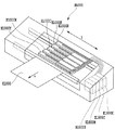
図1は、本発明の実施形態に採用可能なフルライン型のインクジェット記録装置の概略構成を説明するための図である。記録装置本体M4000の内部には、ライン型の記録ヘッドH1000が5つ分、図のようにY方向に並列配置されている。記録ヘッドH1000のそれぞれには、インクを吐出する記録素子がX方向に所定のピッチで配列されており、5つの記録ヘッドH1000は互いに異なる色のインクを吐出する。このように、個々の記録ヘッドから所定の周波数でインクを吐出しつつ、当該周波数に対応した速度で記録媒体K1000をY方向に搬送することにより、記録媒体K1000にはフルカラーの画像が形成される。
Embodiments of the present invention will be described below with reference to the drawings.
(First embodiment)
FIG. 1 is a diagram for explaining a schematic configuration of a full-line type ink jet recording apparatus that can be employed in an embodiment of the present invention. Inside the recording apparatus main body M4000, five line type recording heads H1000 are arranged in parallel in the Y direction as shown in the figure. In each of the recording heads H1000, recording elements for ejecting ink are arranged at a predetermined pitch in the X direction, and the five recording heads H1000 eject inks of different colors. In this way, a full color image is formed on the recording medium K1000 by ejecting ink from each recording head at a predetermined frequency and transporting the recording medium K1000 in the Y direction at a speed corresponding to the frequency. .
本実施形態において、5つの記録ヘッドH1000のうちの4つ、すなわちH1000K、H1000C、H1000MおよびH1000Yは、それぞれブラック(K)、シアン(C)、マゼンタ(M)およびイエロー(Y)を吐出するノーマルヘッドである。一方、これらノーマルヘッド(第1のインクジェット記録ヘッド)と並列して配置された5番目の記録ヘッドH1000Rは、本発明特有のリカバリーヘッド(第2のインクジェット記録ヘッド)である。 In this embodiment, four of the five recording heads H1000, that is, H1000K, H1000C, H1000M, and H1000Y, each ejects black (K), cyan (C), magenta (M), and yellow (Y), respectively. Head. On the other hand, the fifth recording head H1000R arranged in parallel with these normal heads (first ink jet recording head) is a recovery head (second ink jet recording head) unique to the present invention.
5つの記録ヘッドには、装置内部に設置された4つのインクタンクから、チューブを介してインクが供給される。すなわち、記録ヘッドH1000KにはH1800Kよりブラックインクが、記録ヘッドH1000CにはH1800Cよりシアンインクが供給される。また、記録ヘッドH1000MにはH1800Mよりマゼンタインクが、記録ヘッドH1000YにはH1800Yよりイエローインクが供給される。更に、リカバリーヘッドH1000Rには、上記4つのインクタンクより、4色のインクが選択的に供給になっている。ノーマルヘッドおよびリカバリーヘッドH1000Rのインク供給構造については、後に詳しく説明する。 The five recording heads are supplied with ink from four ink tanks installed inside the apparatus via tubes. That is, black ink is supplied to the recording head H1000K from H1800K, and cyan ink is supplied to the recording head H1000C from H1800C. The recording head H1000M is supplied with magenta ink from H1800M, and the recording head H1000Y is supplied with yellow ink from H1800Y. Further, four colors of ink are selectively supplied from the four ink tanks to the recovery head H1000R. The ink supply structure of the normal head and the recovery head H1000R will be described in detail later.
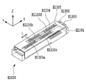
図2は、本実施形態に使用するライン型記録ヘッドH1000の概略構成を説明するための外観斜視図である。本実施形態の記録ヘッドH1000では、インクを吐出する複数の記録素子が高密度に配置された4つの記録素子基板H1100a〜H1100dが、図のようにY方向に互い違いにずれながらX方向に配置されている。隣接する2つの記録素子基板H1100の間には、互いに重複する領域(L)が設けられており、個々の記録素子基板の配置に多少の誤差が含まれる場合であっても、Y方向に搬送される記録媒体上には、この誤差に伴う隙間が生じないようになっている。 FIG. 2 is an external perspective view for explaining a schematic configuration of the line type recording head H1000 used in the present embodiment. In the recording head H1000 of this embodiment, four recording element substrates H1100a to H1100d on which a plurality of recording elements for ejecting ink are arranged at high density are arranged in the X direction while being shifted alternately in the Y direction as shown in the figure. ing. An overlapping region (L) is provided between two adjacent printing element substrates H1100, and even if there is some error in the arrangement of individual printing element substrates, the sheet is conveyed in the Y direction. On the recording medium to be recorded, there is no gap caused by this error.
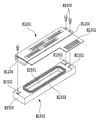
図3は、記録ヘッドH1000の分解斜視図である。本実施形態の記録ヘッドH1000は、インクを吐出する記録素子を構成する記録素子ユニットH1001と、これにインクを供給するためのインク供給ユニットH1002から構成されている。 FIG. 3 is an exploded perspective view of the recording head H1000. The recording head H1000 of this embodiment includes a recording element unit H1001 that constitutes a recording element that ejects ink, and an ink supply unit H1002 for supplying ink thereto.
インク供給ユニットH1002は、インクを収容する共通液室H1501とZ方向基準面H1502が樹脂成形によって形成されたインク供給部材H1500によって主に構成されている。Z方向基準面H1502は、記録ヘッドH1000のZ方向の基準を定め、記録ヘッドユニットH1001を位置決め固定する際に利用される。記録素子ユニットH1001とインク供給ユニットH1002とは、インク供給ユニットのZ基準H1502に記録素子ユニットH1001のZ基準H1206を、ビスH1900等により位置決め固定して結合される。インク供給ユニットH1002の共通液室H1501開口部周囲には第3の封止剤H1503が配されており、上記結合によって共通液室H1501は密閉状態となる。第3の封止剤H1503としては、耐インク性があり、常温で硬化し、更に異種材料間の線膨張差に耐えられる柔軟性のある材料が望ましい。この結合工程の後、記録素子ユニットH1001の外部信号入力端子H1301部分は、インク供給部材H1500の裏面に位置決め固定される。 The ink supply unit H1002 is mainly configured by an ink supply member H1500 in which a common liquid chamber H1501 for storing ink and a Z-direction reference surface H1502 are formed by resin molding. The Z-direction reference surface H1502 defines the Z-direction reference of the recording head H1000, and is used when positioning and fixing the recording head unit H1001. The recording element unit H1001 and the ink supply unit H1002 are coupled to the Z reference H1502 of the ink supply unit by positioning and fixing the Z reference H1206 of the recording element unit H1001 with a screw H1900 or the like. A third sealant H1503 is disposed around the opening of the common liquid chamber H1501 of the ink supply unit H1002, and the common liquid chamber H1501 is hermetically sealed by the above-described combination. As the third sealant H1503, a flexible material that has ink resistance, is cured at room temperature, and can withstand a difference in linear expansion between different materials is desirable. After this coupling step, the external signal input terminal H1301 portion of the recording element unit H1001 is positioned and fixed on the back surface of the ink supply member H1500.
但し、このように、1つの記録素子ユニットH1001に対し1つのインク供給部材H1500が用意されているのは、ノーマルヘッドH1000の場合の構成である。本実施形態のリカバリーヘッドH1000Rについては、1つの記録素子ユニットH1001に対しより小型な4つのインク供給部材H1500が用意されている。ノーマルヘッドとリカバリーヘッドについての構成の違いについては、後に詳しく説明する。 However, in this way, one ink supply member H1500 is prepared for one printing element unit H1001 in the configuration of the normal head H1000. For the recovery head H1000R of the present embodiment, four smaller ink supply members H1500 are prepared for one printing element unit H1001. The difference in configuration between the normal head and the recovery head will be described in detail later.
図4は、記録ヘッドユニットH1001の詳細な構造を説明するための分解斜視図である。本実施形態の記録素子ユニットH1001は、主に、電気配線基板H1300、プレート部材H1400、記録素子基板H1100、支持基板H1200およびフィルタ部材H1600によって構成されている。 FIG. 4 is an exploded perspective view for explaining the detailed structure of the recording head unit H1001. The printing element unit H1001 of this embodiment is mainly configured by an electric wiring board H1300, a plate member H1400, a printing element board H1100, a support board H1200, and a filter member H1600.
電気配線基板H1300は、記録素子基板H1100にインクを吐出するための電気信号を印加するものであり、記録素子基板H1100の電極に対応する電極端子H1302や、装置本体からの電気信号を受信する外部信号入力端子H1301を備えている。また、電気配線基板H1300には、4つの記録素子基板H1100を組み込むための4つの開口部H1303が設けられている。電気配線基板H1300の素材としては、例えば、配線が二層構造のフレキシブル配線基板の表層にポリイミドフィルムを被覆したものが好適に用いられる。電気配線基板H1300の裏面には、プレート部材H1400が接着固定される。 The electrical wiring substrate H1300 applies an electrical signal for ejecting ink to the recording element substrate H1100. The electrical wiring substrate H1300 receives an electrical signal from the electrode terminal H1302 corresponding to the electrode of the recording element substrate H1100 or the apparatus main body. A signal input terminal H1301 is provided. The electric wiring board H1300 is provided with four openings H1303 for incorporating the four recording element substrates H1100. As a material for the electric wiring board H1300, for example, a wiring layer in which a surface of a flexible wiring board having a two-layer structure is coated with a polyimide film is preferably used. A plate member H1400 is bonded and fixed to the back surface of the electrical wiring board H1300.
本実施形態のプレート部材H1400は、4つの記録素子基板H1100を取り込む開口部H1402を有するSUS板によって構成されている。但し、本実施形態のプレート基板の材料はSUSに限定されるものではい。耐インク性を有し、良好な平面性を有する材料であれば、他の材料であっても好適に用いることが出来る。プレート部材H1400は、支持基板H1200に接着固定された記録素子基板H1100を、開口部1402によって取り込むように、支持基板H1200に接着固定される。 The plate member H1400 of the present embodiment is configured by a SUS plate having an opening H1402 for taking in the four recording element substrates H1100. However, the material of the plate substrate of this embodiment is not limited to SUS. Any other material can be suitably used as long as it has ink resistance and good planarity. The plate member H1400 is bonded and fixed to the support substrate H1200 so that the recording element substrate H1100 bonded and fixed to the support substrate H1200 is taken in by the opening 1402.
このような接着工程において、プレート部材H1400の開口部H1402と記録素子基板H1100の側面によって形成される溝部には、図2を参照するに、第1の封止剤H1304が充填される。これによって、電気配線基板H1300の電気実装部が封止される。また、記録素子基板の電極H1103についても、第2の封止剤H1305によって封止され、電気接続部分はインクによる腐食や外的衝撃から保護される。 In such a bonding process, the groove formed by the opening H1402 of the plate member H1400 and the side surface of the recording element substrate H1100 is filled with the first sealant H1304, as shown in FIG. Thereby, the electrical mounting portion of the electrical wiring board H1300 is sealed. Further, the electrode H1103 of the recording element substrate is also sealed by the second sealant H1305, and the electrical connection portion is protected from ink corrosion and external impact.
なお、記録素子基板H1100の電極H1103と電気配線基板H1300の電極端子H1302は、金ワイヤーを用いたワイヤーボンディング技術により接続され、これによって電気配線基板H1300と記録素子基板H1100との電気的接続がなされる。 Note that the electrode H1103 of the recording element substrate H1100 and the electrode terminal H1302 of the electric wiring substrate H1300 are connected by a wire bonding technique using a gold wire, whereby the electric wiring substrate H1300 and the recording element substrate H1100 are electrically connected. The
本実施形態の支持基板H1200は、主に記録素子基板H1100を支持する役割を果たし、厚さ3〜10mm程度のアルミナ(Al2O3)材料で形成されている。但し、支持基板H1200の素材はアルミナに限られることはない。例えば、シリコン(Si)、カーボングラファイト、ジルコニア、窒化珪素(Si3N4)、炭化珪素(SiC)、モリブデン(Mo)、タングステン(W)のような材料であってもよい。いずれにせよ、記録素子基板H1100の材料の線膨張率と同等の線膨張率を有し、かつ、記録素子基板H1100の材料の熱伝導率と同等もしくは同等以上の熱伝導率を有する材料であれば、本実施形態に好適に用いることが出来る。 The support substrate H1200 of this embodiment mainly plays a role of supporting the recording element substrate H1100, and is formed of an alumina (Al 2 O 3 ) material having a thickness of about 3 to 10 mm. However, the material of the support substrate H1200 is not limited to alumina. For example, materials such as silicon (Si), carbon graphite, zirconia, silicon nitride (Si 3 N 4 ), silicon carbide (SiC), molybdenum (Mo), and tungsten (W) may be used. In any case, a material having a linear expansion coefficient equivalent to that of the material of the recording element substrate H1100 and a thermal conductivity equal to or greater than or equal to the thermal conductivity of the material of the recording element substrate H1100. Thus, it can be suitably used in the present embodiment.
支持基板H1200には、記録素子基板H1100にインクを供給するためのインク供給口H1201が形成されている。そして、記録素子基板H1100のインク供給口H1101が支持基板H1200のインク供給口H1201に対応するように、2つの基板が位置精度良く接着固定される。接着剤としては、粘度が低く、接触面に形成される接着層が薄く、硬化後に比較的高い硬度を有し、さらに耐インク性を有するものが望ましい。例えば、エポキシ樹脂を主成分とした熱硬化接着剤、もしくは紫外線硬化併用型の熱硬化接着剤が好適に用いられる。接着層の厚みは50μm以下が望ましいが、特に記録素子基板H1100から発生する熱を支持基板H1200の側へ誘導するためには、10μm以下が望ましい。 In the support substrate H1200, an ink supply port H1201 for supplying ink to the recording element substrate H1100 is formed. Then, the two substrates are bonded and fixed with high positional accuracy so that the ink supply port H1101 of the recording element substrate H1100 corresponds to the ink supply port H1201 of the support substrate H1200. The adhesive preferably has a low viscosity, a thin adhesive layer formed on the contact surface, a relatively high hardness after curing, and ink resistance. For example, a thermosetting adhesive mainly composed of an epoxy resin or a UV-curing combined thermosetting adhesive is preferably used. The thickness of the adhesive layer is desirably 50 μm or less, but is desirably 10 μm or less in order to induce heat generated from the recording element substrate H1100 toward the support substrate H1200.
なお、支持基板H1200には、記録ヘッドユニットH1001がインク供給ユニットH1002に接着する際の位置決め基準となる、X方向基準H1204、Y方向基準H1205、Z方向基準H1206が備えられている。 The support substrate H1200 is provided with an X-direction reference H1204, a Y-direction reference H1205, and a Z-direction reference H1206, which are positioning references when the recording head unit H1001 adheres to the ink supply unit H1002.
支持基板H1200の裏面側インク供給口H1201には、インク供給ユニットH1500から記録素子基板H1100に供給されるインク中に混入された異物を取り除くためのフィルタ部材H1600が接着固定される。 A filter member H1600 for removing foreign matter mixed in the ink supplied from the ink supply unit H1500 to the recording element substrate H1100 is bonded and fixed to the back surface side ink supply port H1201 of the support substrate H1200.
図5(a)および(b)は、記録素子基板H1100の詳細な構成を説明するための図である。 図5(a)は、記録素子基板H1100の斜視図であり、図5(b)は同図(a)に示すA−A断面図である。 5A and 5B are diagrams for explaining the detailed configuration of the recording element substrate H1100. FIG. 5A is a perspective view of the recording element substrate H1100, and FIG. 5B is a cross-sectional view taken along line AA shown in FIG.
本実施形態の記録素子基板H1100は、厚さ0.5〜1mmのSi基板H1108上に、ノズルプレートH1110が積層されることにより構成される。Si基板H1108には、Si基板H1108の結晶方位を利用して、インク供給口H1101となる長溝状の貫通口が形成される。具体的には、例えば上記Siが、ウエハー面に<100>、厚さ方向に<111>の結晶方位を持つ場合、アルカリ系(KOH、TMAH、ヒトラジン等)の異方性エッチングにより、約54.7度の内角を有するインク供給口H1101が形成される。 The recording element substrate H1100 of this embodiment is configured by laminating a nozzle plate H1110 on a Si substrate H1108 having a thickness of 0.5 to 1 mm. In the Si substrate H1108, a long groove-like through-hole serving as the ink supply port H1101 is formed using the crystal orientation of the Si substrate H1108. Specifically, for example, when the Si has a <100> crystal orientation on the wafer surface and a <111> crystal orientation in the thickness direction, it is about 54 by alkaline anisotropic etching (KOH, TMAH, human azine, etc.). An ink supply port H1101 having an inner angle of 7 degrees is formed.
Si基板H1108上には、インク供給口H1101の両側に所定のピッチで配列する電気熱変換素子H1102や、これら電気熱変換素子H1102のそれぞれを電極H1103と接続するAl等の電気配線が、成膜技術によって形成されている。インク供給口H1101の両側にある2列の電気熱変換素子列は、X方向に互いに半ピッチずれて配置している。 On the Si substrate H1108, electrothermal conversion elements H1102 arranged at a predetermined pitch on both sides of the ink supply port H1101, and electrical wiring such as Al for connecting each of the electrothermal conversion elements H1102 to the electrode H1103 are formed. Formed by technology. The two electrothermal conversion element arrays on both sides of the ink supply port H1101 are arranged with a half-pitch shift in the X direction.
ノズルプレートH1110には、インク流路H1104とノズルH1105が、フォトリソ技術によって形成されている。インク流路H1104は、Si基板H1108のインク供給口H1101から供給されたインクを、個々の電気熱変換素子H1102が位置する発泡室H1107へと導くように形成されている。また、ノズルH1105は、電気熱変換素子H1102が配備された発泡室H1107の位置それぞれに対して設けられ、インク流路H1104から供給されたインクを、吐出口へ導く液路となっている。 In the nozzle plate H1110, an ink flow path H1104 and a nozzle H1105 are formed by photolithography. The ink flow path H1104 is formed so as to guide the ink supplied from the ink supply port H1101 of the Si substrate H1108 to the bubbling chamber H1107 where the individual electrothermal conversion elements H1102 are located. In addition, the nozzle H1105 is provided for each position of the foaming chamber H1107 in which the electrothermal conversion element H1102 is disposed, and serves as a liquid path that guides the ink supplied from the ink flow path H1104 to the ejection port.
このように形成されたSi基板H1108とノズルプレートH1110が図のように積層接着されることにより、記録素子基板H1100が完成する。吐出動作を行う際、該当する記録素子の電気熱変換素子H1102に電圧パルスが印加される。すると、電気熱変換素子H1102の急激な発熱によって、これに接触するインク中に発泡が生じ、この発泡のエネルギによってノズルH1105からインクが滴として押し出される仕組みになっている。 The Si substrate H1108 and the nozzle plate H1110 thus formed are laminated and bonded as shown in the drawing, thereby completing the recording element substrate H1100. When performing the ejection operation, a voltage pulse is applied to the electrothermal conversion element H1102 of the corresponding recording element. Then, due to the rapid heat generation of the electrothermal conversion element H1102, foaming occurs in the ink in contact therewith, and the ink is pushed out as droplets from the nozzle H1105 by the energy of this foaming.
図6は、1つの支持基板H1200上に配列する4つの記録素子基板H1100a〜H1100dの配線構造を説明するための回路図である。個々の記録素子基板には、図7および図8に示す奇数(ODD)番目の記録素子用の駆動回路および偶数(EVEN)番目の記録素子用の駆動回路が配備されている。ここで、奇数番目の記録素子および偶数番目の記録素子とは、図5で説明した、インク供給口H1101の両側で互いに半ピッチずれて配置する2列の電気熱変換素子列(奇数記録素子列および偶数記録素子列)に相当する。そして、これら2つの駆動回路は記録素子基板上に半導体プロセスにより形成される。 FIG. 6 is a circuit diagram for explaining a wiring structure of four recording element substrates H1100a to H1100d arranged on one support substrate H1200. Each of the recording element substrates is provided with a drive circuit for odd (ODD) th recording elements and a drive circuit for even (EVEN) th recording elements shown in FIGS. Here, the odd-numbered printing elements and the even-numbered printing elements are the two electrothermal conversion element rows (odd-numbered printing device rows) arranged with a half-pitch shift on both sides of the ink supply port H1101 described in FIG. And even recording element arrays). These two drive circuits are formed on the recording element substrate by a semiconductor process.
ヒート信号HEATOおよびデータ信号IDATAOは、奇数用の駆動回路から、奇数記録素子列に含まれる個々の記録素子に対応して取り出されている。同じく、ヒート信号HEATEおよびデータ信号IDATAEは、偶数用の駆動回路から偶数記録素子列に含まれる個々の記録素子に対応して取り出されている。これ以外の信号LTCLKおよびDCLK、および電源系であるVH、GNDH、VDD、GNDは、全駆動回路に共通な配線となっている。信号線LTCLK、DCLK、HEAT、IDATAは外部信号入力端子H1301に接続され、電源系であるVH、GNDH、VDD、GNDは電源端子H1302に接続されている。 The heat signal HEATO and the data signal IDATAO are extracted from the odd number drive circuit corresponding to the individual print elements included in the odd number print element array. Similarly, the heat signal HEATE and the data signal IDATAE are extracted from the even-number drive circuit in correspondence with the individual print elements included in the even-number print element array. The other signals LTCLK and DCLK and the power supply systems VH, GNDH, VDD, GND are wirings common to all the drive circuits. The signal lines LTCLK, DCLK, HEAT and IDATA are connected to the external signal input terminal H1301, and the power supply systems VH, GNDH, VDD and GND are connected to the power supply terminal H1302.
図7は、奇数用の駆動回路H1100−Oの構成を説明するための概略回路図である。
ここでは、奇数記録素子列および偶数記録素子列ともに640個の記録素子を有するものとする。ヒータH1102−1〜H1102〜1279は、奇数記録素子列に配され、個々の記録素子に対応する吐出用のヒータであり、これらは20個ずつ、32の駆動ブロックに分割されている。個々の駆動ブロックはBE0〜31の信号により選択され、時分割で駆動される。個々の駆動ブロック内に属する20個のヒータは、トランジスタE1006−1〜20のON/OFFにより吐出するか否かが決定させる。
FIG. 7 is a schematic circuit diagram for explaining the configuration of the odd number drive circuit H1100-O.
Here, it is assumed that both the odd number recording element array and the even number recording element array have 640 recording elements. The heaters H1102-1 to H1102 to 1279 are ejection heaters arranged in odd-numbered printing element arrays and corresponding to individual printing elements, each of which is divided into 32 drive blocks. Individual drive blocks are selected by signals BE0 to 31 and are driven in a time division manner. The 20 heaters belonging to each drive block determine whether or not to discharge by turning ON / OFF the transistors E1006-1 to E1006-1.
図9は、各信号の発信状態を示すタイミングチャートである。以下図7で示す各機構と図9のタイミングチャートを参照しながら、駆動回路E1000−Oにおける駆動動作を説明する。 FIG. 9 is a timing chart showing the transmission state of each signal. Hereinafter, the drive operation in the drive circuit E1000-O will be described with reference to the mechanisms shown in FIG. 7 and the timing chart of FIG.
PRINT信号は1カラムの吐出を開始するタイミングを与えるパルス信号で、パルスの立ち上がりタイミングで駆動回路の動作が開始する。駆動回路が動作を開始すると最初にLTCLKが生成され、それから数100ps後に転送クロックDCLKが転送データ分、ここでは25クロック出力される。IDATA1〜8の各信号にはDCLKに同期して転送データが出力され、25ビットシフトレジスタE1001にシリアル転送される。そして、シフトレジスタE1001に格納されたデータは次の駆動ブロックの最初に出力されるLTCLKのタイミングで25ビットラッチE1002に記憶される。そのため、最初の転送データにしたがって実際の駆動がなされるのはその次のブロックの転送が行われるタイミングである。 The PRINT signal is a pulse signal that gives the timing for starting ejection of one column, and the operation of the drive circuit starts at the rise timing of the pulse. When the drive circuit starts operation, LTCLK is first generated, and after several hundreds ps, the transfer clock DCLK is output for the transfer data, 25 clocks here. Transfer data is output to each signal of IDATA1 to 8 in synchronization with DCLK and serially transferred to a 25-bit shift register E1001. The data stored in the shift register E1001 is stored in the 25-bit latch E1002 at the timing of LTCLK output at the beginning of the next drive block. Therefore, the actual driving is performed according to the first transfer data at the timing when the next block is transferred.
ここで転送されるデータ内容は駆動されるブロックの番号BENB0〜4が5ビット、続いてそのブロックで駆動される電気熱変換素子H1102の駆動データが20ビットの合計25ビットである。駆動ブロックBENB0〜4は5→3デコーダE1003でBE0〜31にデコードされ、トランジスタE1005−1〜32のベース電極に接続される。よって、常に32個のトランジスタE1005−1〜32の内、1個だけが駆動されることになり、指定ブロックに属する電気熱変換素子の一端にのみ駆動電源(VH)が供給される。 The data content transferred here is a total of 25 bits, ie, the drive block number BENB0-4 is 5 bits and the drive data of the electrothermal transducer H1102 driven in that block is 20 bits. The drive blocks BENB0-4 are decoded into BE0-31 by the 5 → 3 decoder E1003 and connected to the base electrodes of the transistors E1005-1-312. Therefore, only one of the 32 transistors E1005-1 to 32 is always driven, and the drive power supply (VH) is supplied only to one end of the electrothermal conversion element belonging to the designated block.
一方、電気熱変換素子H1102−1〜1279のもう一端はセグメント毎に32個ずつ並列接続されており、それぞれ20個のトランジスタE1006−1〜20のコレクタ電極に接続されている。これらのトランジスタの駆動はベース電極に接続されているANDゲートE1004−1〜20出力により制御される。ANDゲートの一方の入力には20ビットの駆動データ信号が接続され、もう一方には電気熱変換素子を実際に駆動するタイミングを与えるパルス信号HEAT1〜8が接続されている。よって、トランジスタE1006−1〜20は上記2信号のANDで制御されることになり、その結果20ビットの駆動データによって指定されたセグメントに対してHEAT1〜8のパルスタイミングで駆動されることになる。 On the other hand, the other ends of the electrothermal transducers H1102-1 to 1279 are connected in parallel by 32 for each segment, and are connected to the collector electrodes of 20 transistors E1006-1 to 20, respectively. The driving of these transistors is controlled by the outputs of AND gates E1004-1 to 20 connected to the base electrode. A 20-bit drive data signal is connected to one input of the AND gate, and pulse signals HEAT1 to 8 for giving timing for actually driving the electrothermal transducer are connected to the other input. Therefore, the transistors E1006-1 to 20 are controlled by AND of the two signals, and as a result, the segment specified by the 20-bit drive data is driven at the pulse timing of HEAT1 to 8. .
以上のようにして、PRINT信号が発効すると駆動回路が動作を開始し、最初に0ブロック目が駆動され順次1、2、…となって、最後に31ブロック目は駆動が完了して、全記録素子基板の全記録素子の吐出が制御される。 As described above, when the PRINT signal is activated, the drive circuit starts to operate, the first block is driven first, sequentially becomes 1, 2,..., And finally the 31st block is completely driven. The ejection of all the recording elements on the recording element substrate is controlled.
次に、本実施形態におけるノーマルヘッドH1000とリカバリーヘッドH1000Rのインク供給構造の違いについて説明する。 Next, the difference in ink supply structure between the normal head H1000 and the recovery head H1000R in this embodiment will be described.
図10は、本実施形態のノーマルヘッドH1000(第1のインクジェット記録ヘッド)における、記録素子ユニットH1001と、これにインクを供給するためのインク供給ユニットH1002の構造を説明するための、断面図および平面図である。既に説明した様に、支持基板H1200には記録素子基板H1100a、H1100b、H1100c、H1100dが互い違いに配置され、インク供給部材H1500の共通液室H1501に貯蔵されたインクは、上記4つの記録素子基板に共通して供給される。インク供給部材H1500には、所定のインクタンクからインクを供給するためのインク供給系接続口H1505が、インクIN、インクOUTで1セット分配備されている。このような構成により、ノーマルヘッドH1000では、4つの記録素子基板H1100a〜H1100dでは、同じ種類のインクが吐出されることになる。 FIG. 10 is a cross-sectional view for explaining the structure of a recording element unit H1001 and an ink supply unit H1002 for supplying ink to the normal head H1000 (first ink jet recording head) of the present embodiment. It is a top view. As already described, the recording element substrates H1100a, H1100b, H1100c, and H1100d are alternately arranged on the support substrate H1200, and the ink stored in the common liquid chamber H1501 of the ink supply member H1500 is transferred to the four recording element substrates. Commonly supplied. The ink supply member H1500 is provided with an ink supply system connection port H1505 for supplying ink from a predetermined ink tank for one set of ink IN and ink OUT. With such a configuration, the same type of ink is ejected from the four recording element substrates H1100a to H1100d in the normal head H1000.
図11は、本実施形態のリカバリーヘッドH1000R(第2のインクジェット記録ヘッド)における、記録素子ユニットH1001と、これにインクを供給するためのインク供給ユニットH1002Rの構造を説明するための、断面図および平面図である。ノーマルヘッドと同様、支持基板H1200には4つの記録素子基板H1100a、H1100b、H1100c、H1100dの4枚が互い違いに配置されている。 FIG. 11 is a cross-sectional view for explaining the structure of a recording element unit H1001 and an ink supply unit H1002R for supplying ink to the recovery head H1000R (second ink jet recording head) of the present embodiment. It is a top view. Similar to the normal head, four recording element substrates H1100a, H1100b, H1100c, and H1100d are alternately arranged on the support substrate H1200.
リカバリーヘッドH1000Rにインクを供給するインク供給ユニットH1002Rは、小容量の共通液室をそれぞれ備えた4つのインク供給部材H1500a、H1500b、H1500c、H1500dから構成されている。これにより、インク供給ユニットH1002Rは、4つの記録素子基板それぞれに異なるインクを供給できるようになっている。供給部材H1500aからは記録素子基板H1100aに、供給部材H1500bからは記録素子基板H1100bに、供給部材H1500cからは記録素子基板H1100cに、供給部材H1500dからは記録素子基板H1100dに、夫々インクが供給される。個々のインク供給部材には、所望のインクタンクからインクを供給するためのインク供給系接続口H1505が、1セットずつ配備されている。このような構成により、リカバリーヘッドH1000Rでは、4つの記録素子基板H1100a〜H1100dが吐出するインクの種類を、選択的に切り替えることが出来る。既に図1で説明したように、本実施形態の記録装置は、図10で説明した構成のノーマルヘッドを4つと、図11で説明した構成のリカバリーヘッドを1つ、記録媒体の搬送方向に対し、並列して備えている。 An ink supply unit H1002R that supplies ink to the recovery head H1000R includes four ink supply members H1500a, H1500b, H1500c, and H1500d each having a small-capacity common liquid chamber. Accordingly, the ink supply unit H1002R can supply different inks to the four recording element substrates. Ink is supplied from the supply member H1500a to the recording element substrate H1100a, from the supply member H1500b to the recording element substrate H1100b, from the supply member H1500c to the recording element substrate H1100c, and from the supply member H1500d to the recording element substrate H1100d. . Each ink supply member is provided with one set of ink supply system connection ports H1505 for supplying ink from a desired ink tank. With such a configuration, the recovery head H1000R can selectively switch the type of ink ejected by the four recording element substrates H1100a to H1100d. As already described with reference to FIG. 1, the recording apparatus according to the present embodiment includes four normal heads having the configuration described in FIG. 10 and one recovery head having the configuration described in FIG. , In parallel.
以上説明した記録装置および記録ヘッドを用い、本実施形態における吐出不良な記録素子に対する画像補完方法を、いくつかの実施例に基づいて具体的に説明する。 Using the recording apparatus and the recording head described above, the image complementing method for the defectively ejected recording element in the present embodiment will be specifically described based on several examples.
図12は、本実施例における4つのノーマルヘッドH1000C〜H1000Kと1つのリカバリーヘッドH1000Rから吐出するインクの種類を説明するための図である。図において、H1000C、H1000M、H1000YおよびH1000Kはシアン、マゼンタ、イエローおよびブラックを、全ての記録素子から吐出するノーマルヘッドである。既に説明したように、個々の記録ヘッドは、片側640個の2列の記録素子列を備えた記録素子基板を4枚配置して構成されている。すなわち、1つの記録ヘッドには5120個の記録素子が配備されている。このような状況において、吐出状態が不良である記録素子を全く含まない状態で記録ヘッドを製造することは難しく、初期段階においては、1〜数個の不良記録素子がしばしば存在している。図では、個々のノーマルヘッドにおいて、×印を示した箇所に吐出状態が不良な記録素子が存在する場合を示している。 FIG. 12 is a diagram for explaining the types of ink ejected from the four normal heads H1000C to H1000K and one recovery head H1000R in the present embodiment. In the figure, H1000C, H1000M, H1000Y, and H1000K are normal heads that discharge cyan, magenta, yellow, and black from all printing elements. As described above, each recording head is configured by arranging four recording element substrates each having 640 two recording element arrays on one side. In other words, 5120 recording elements are provided in one recording head. In such a situation, it is difficult to manufacture a recording head in a state that does not include a recording element having a defective ejection state, and there are often one to several defective recording elements in the initial stage. In the drawing, a case is shown where there is a recording element having a defective ejection state at a location indicated by a cross in each normal head.
本実施例では、ノーマルヘッドの吐出状態が不良な記録素子が記録するべき位置を、リカバリーヘッドによって補完記録出来るように、リカバリーヘッドのインク供給接続口H1505とインクタンクとを接続する。すなわち、図12を参照するに、シアンヘッドH1000Cの吐出不良位置をリカバリーヘッドH1000Rの記録素子基板H1100aで補完するために、リカバリーヘッドH1000Rのインク供給部材H1500aはシアンタンクH1800Cと接続させる。また、マゼンタヘッドH1000Mの吐出不良位置をリカバリーヘッドH1000Rの記録素子基板H1100bで補完するために、リカバリーヘッドH1000Rのインク供給部材H1500bはマゼンタタンクH1800Mと接続させる。また、イエローヘッドH1000Yの吐出不良位置をリカバリーヘッドH1000Rの記録素子基板H1100cで補完するために、リカバリーヘッドH1000Rのインク供給部材H1500cはイエロータンクH1800Yと接続させる。さらに、ブラックヘッドH1000Kの吐出不良位置をリカバリーヘッドH1000Rの記録素子基板H1100dで補完するために、リカバリーヘッドH1000Rのインク供給部材H1500dはブラックタンクH1800Kと接続させる。
以上説明した接続構成のもと、個々のノーマルヘッドにおける吐出状態が不良な記録素子(×印)の駆動を停止し、当該記録素子に印加すべき駆動電圧を、この位置に対応するリカバリーヘッドの記録素子に印加する。これにより、ノーマルヘッドの吐出状態が不良な記録素子が記録すべきドットは、リカバリーヘッドの記録素子によって、同じインク色で補完記録される。結果、初期段階において、図12のような数個の不良記録素子が含まれるノーマルヘッドを用いても、ドットの欠落や白すじのない画像を出力することが出来る。
In this embodiment, the recovery head ink supply connection port H1505 and the ink tank are connected so that the recovery head can complementarily record the position at which the recording element with a defective ejection state of the normal head should be recorded. That is, referring to FIG. 12, in order to complement the ejection failure position of the cyan head H1000C with the recording element substrate H1100a of the recovery head H1000R, the ink supply member H1500a of the recovery head H1000R is connected to the cyan tank H1800C. Further, in order to complement the ejection failure position of the magenta head H1000M with the recording element substrate H1100b of the recovery head H1000R, the ink supply member H1500b of the recovery head H1000R is connected to the magenta tank H1800M. Further, in order to supplement the ejection failure position of the yellow head H1000Y with the recording element substrate H1100c of the recovery head H1000R, the ink supply member H1500c of the recovery head H1000R is connected to the yellow tank H1800Y. Furthermore, in order to complement the ejection failure position of the black head H1000K with the recording element substrate H1100d of the recovery head H1000R, the ink supply member H1500d of the recovery head H1000R is connected to the black tank H1800K.
Under the connection configuration described above, the drive of the recording element (x mark) in which the ejection state of each normal head is defective is stopped, and the drive voltage to be applied to the recording element is set to the recovery head corresponding to this position. Applied to the recording element. As a result, the dots to be recorded by the recording element with the defective ejection state of the normal head are complementarily recorded with the same ink color by the recording element of the recovery head. As a result, in the initial stage, even if a normal head including several defective recording elements as shown in FIG. 12 is used, an image without missing dots or white lines can be output.
本実施形態では、図11に示したようなインク供給構造を有しているので、リカバリーヘッドH1000Rに配置される4つのインク供給部材H1500a〜H1500dに接続するインクタンクを、選択的に切り替えることが出来る。その結果、吐出不良な記録素子がいずれのノーマルヘッドのいずれの位置に存在した場合であっても、リカバリーヘッドH1000Rによる、同種類のインクを用いた補完記録が可能になっている。但し、リカバリーヘッドであっても、1つの記録素子基板からは1種類のインクしか吐出することは出来ない。よって、記録ヘッド組み立て時においては、吐出不良の記録素子が各色で異なる位置の記録素子基板に存在するように、4つのノーマルヘッドの4つの記録素子基板の配置が配慮されることが望まれる。このようにすれば、記録ヘッド製造時の歩留まりを下げることなく、ドットの欠落や白すじのない高品位で安定した画像を高速に出力することが出来る。 In the present embodiment, since the ink supply structure as shown in FIG. 11 is provided, the ink tanks connected to the four ink supply members H1500a to H1500d arranged in the recovery head H1000R can be selectively switched. I can do it. As a result, it is possible to perform complementary recording using the same type of ink by the recovery head H1000R, regardless of the position of any normal head where there is a defective ejection element. However, even with the recovery head, only one type of ink can be ejected from one recording element substrate. Therefore, at the time of assembling the recording head, it is desirable to consider the arrangement of the four recording element substrates of the four normal heads so that the defective recording elements exist on the recording element substrates at different positions for each color. In this way, it is possible to output a high-quality and stable image without missing dots or white streaks at high speed without lowering the yield at the time of manufacturing the recording head.
図13(a)〜(c)は、本実施形態のインクジェット記録装置において、使用に伴って新たに吐出状態が不良な記録素子が発生した場合の対応方法を説明するための図である。図13(a)は初期状態を示し、ブラックのノーマルヘッドH1000Kにおいて、×印を示した箇所に吐出状態が不良な記録素子が存在する場合を示している。実施例1と同じように、ブラックヘッドH1000Kの吐出不良位置をリカバリーヘッドH1000Rの記録素子基板H1100dで補完するために、インク供給部材H1500dはブラックタンクH1800Kと接続されている。 FIGS. 13A to 13C are views for explaining a method for dealing with a case where a recording element having a newly ejected state is newly generated with use in the ink jet recording apparatus of the present embodiment. FIG. 13A shows an initial state, and shows a case where a recording element having a defective ejection state exists at a location indicated by a cross in the black normal head H1000K. As in the first embodiment, the ink supply member H1500d is connected to the black tank H1800K in order to supplement the ejection failure position of the black head H1000K with the recording element substrate H1100d of the recovery head H1000R.
図13(b)は、記録ヘッドの使用に伴って、イエローのノーマルヘッドH1000Yに、吐出状態が不良な記録素子が×印を示した箇所に新たに発生した状態を示している。本実施例では、このように使用の途中で新たな不良素子が発生した場合でも、不良素子の発生した位置に対応するリカバリーヘッドの記録素子基板と、補完すべき色に対応したインクタンクとを、適切なタイミングで連結することが出来るようになっている。すなわち、図13(b)の場合では、イエローヘッドH1000Yの吐出不良位置をリカバリーヘッドH1000Rの記録素子基板H1100bで補完するために、インク供給部材H1500bはイエロータンクH1800Yと適切なタイミングで接続される。 FIG. 13B shows a state in which a recording element having a defective ejection state is newly generated at a position indicated by an X mark in the yellow normal head H1000Y as the recording head is used. In this embodiment, even when a new defective element occurs in the middle of use as described above, the recording element substrate of the recovery head corresponding to the position where the defective element occurs and the ink tank corresponding to the color to be complemented are provided. , It can be connected at an appropriate timing. That is, in the case of FIG. 13B, the ink supply member H1500b is connected to the yellow tank H1800Y at an appropriate timing in order to supplement the ejection failure position of the yellow head H1000Y with the recording element substrate H1100b of the recovery head H1000R.
一方、図13(c)は、記録ヘッドの使用に伴って、ブラックのノーマルヘッドH1000Kの別の位置に、吐出状態が不良な記録素子が×印を示した箇所に新たに発生した状態を示している。図13(c)の場合では、ブラックヘッドH1000Kの吐出不良位置をリカバリーヘッドH1000Rの記録素子基板H1100bで補完するために、インク供給部材H1500bはブラックタンクH1800Kと適切なタイミングで接続される。 On the other hand, FIG. 13C shows a state in which a recording element having a defective ejection state is newly generated at another position of the black normal head H1000K along with the use of the recording head. ing. In the case of FIG. 13C, the ink supply member H1500b is connected to the black tank H1800K at an appropriate timing in order to supplement the ejection failure position of the black head H1000K with the recording element substrate H1100b of the recovery head H1000R.
インクジェット記録ヘッドにおいては、使用に伴って吐出状態が不良となる記録素子がこのように新たに発生する場合はあるが、発生する記録ヘッドや発生位置を予測することは難しい。しかし、上述したように、本実施例においては、リカバリーヘッドH1000Rに配置される4つのインク供給部材に接続するインクタンクを、適宜、選択的に切り替えることが出来るようになっている。よって、吐出不良な記録素子がいずれのノーマルヘッドのいずれの位置に不意に発生した場合であっても、リカバリーヘッドH1000Rによる、同種類のインクを用いた補完記録を即座に実行し、白すじのない高品位な画像の高速出力を維持することが可能となる。 In an ink jet recording head, there may be a case where a recording element whose ejection state becomes defective with use is newly generated in this way. However, it is difficult to predict the recording head and the generation position. However, as described above, in this embodiment, the ink tanks connected to the four ink supply members arranged in the recovery head H1000R can be selectively switched as appropriate. Therefore, even if a recording element with poor ejection is unexpectedly generated at any position of any normal head, complementary recording using the same type of ink is immediately performed by the recovery head H1000R, and white streak is detected. It is possible to maintain high-speed output of no high-quality images.
図14は、本実施例における4つのノーマルヘッドH1000C〜H1000Kと2つのリカバリーヘッドH1000R1およびH1000R2から吐出するインクの種類を説明するための図である。4つのノーマルヘッドにおいては、例えば図14のマゼンタヘッドH1000MとブラックヘッドH1000Kのように、同じ記録素子基板の位置(H1100d)に、吐出状態が不良である記録素子が発生してしまう場合もある。しかし、上記実施例のようにリカバリーヘッドH1000Rを1つしか備えない構成においては、どちらか一方のノーマルヘッドの補完記録しか行うことが出来ない。このような状況に対応するため、本実施例では、4つのノーマルヘッドに対し2つのリカバリーヘッドを用いて補完対応出来るようにしている。 FIG. 14 is a diagram for explaining the types of ink ejected from the four normal heads H1000C to H1000K and the two recovery heads H1000R1 and H1000R2 in this embodiment. In the four normal heads, for example, a recording element having a defective ejection state may occur at the position (H1100d) of the same recording element substrate, such as the magenta head H1000M and the black head H1000K in FIG. However, in the configuration in which only one recovery head H1000R is provided as in the above embodiment, only complementary recording of either one of the normal heads can be performed. In order to cope with such a situation, in the present embodiment, the four normal heads can be complemented by using two recovery heads.
本実施例では、ブラックヘッドH1000Kの吐出不良位置をリカバリーヘッドH1000R1の記録素子基板H1100dで補完するために、リカバリーヘッドH1000R1のインク供給部材H1500dはブラックタンクH1800Kと接続させている。一方、上記ブラックヘッドの不良記録素子と同じ位置にあるマゼンタヘッドH1000Mの不良記録素子については、リカバリーヘッドH1000R2の記録素子基板H1100dで補完対応する。そのため、リカバリーヘッドH1000R2のインク供給部材H1500dはマゼンタタンクH1800Mと接続させている。 In this embodiment, the ink supply member H1500d of the recovery head H1000R1 is connected to the black tank H1800K in order to supplement the ejection failure position of the black head H1000K with the recording element substrate H1100d of the recovery head H1000R1. On the other hand, the defective recording element of the magenta head H1000M at the same position as the defective recording element of the black head is complemented by the recording element substrate H1100d of the recovery head H1000R2. Therefore, the ink supply member H1500d of the recovery head H1000R2 is connected to the magenta tank H1800M.
このような構成であれば、複数のノーマルヘッドにおいて、同じ記録素子基板の位置に吐出不良の記録素子が存在する場合であっても、2つのリカバリーヘッドのインク供給部材を、それぞれ異なるインクタンクと接続することが出来る。よって、実施例1や実施例2の場合に比べて、記録ヘッド製造時の歩留まりを更に上昇させることが出来る一方、白すじのない高品位な画像の高速出力を、より安定して維持することが可能となる。 With such a configuration, even in the case where there are printing elements with defective ejection at the position of the same printing element substrate in a plurality of normal heads, the ink supply members of the two recovery heads are set to different ink tanks. It can be connected. Therefore, the yield at the time of manufacturing the recording head can be further increased as compared with the case of the first and second embodiments, and the high-speed output of a high-quality image without white streaks can be maintained more stably. Is possible.
図15は、本実施例における記録ヘッドの配置構成を示した図である。本実施例では1つのリカバリーヘッドH1000Rを、4つのノーマルヘッドの中央に配置させている。図12や図14のような配置の場合、ブラックヘッドH1000KとリカバリーヘッドH1000Rとの距離は短いが、シアンヘッドH1000CとリカバリーヘッドH1000Rとの距離は長い。このようなノーマルヘッドとリカバリーヘッド距離は、記録媒体に対するノーマルヘッドによる記録とリカバリーヘッドによる記録との間に、時間差を招致する。 FIG. 15 is a diagram showing an arrangement configuration of recording heads in the present embodiment. In this embodiment, one recovery head H1000R is arranged at the center of four normal heads. In the arrangement shown in FIGS. 12 and 14, the distance between the black head H1000K and the recovery head H1000R is short, but the distance between the cyan head H1000C and the recovery head H1000R is long. Such a distance between the normal head and the recovery head causes a time difference between recording by the normal head and recording by the recovery head on the recording medium.
一般に、インクジェット記録においては、記録媒体に対しほとんど同じタイミングでインクを付与して得られる画像と、異なる複数のタイミングでインクを付与して得られる画像との間で、濃度差が生じることが知られている。すなわち、不良記録素子の部分のみ周囲とは異なるタイミングでリカバリーヘッドによる補完記録が行われた画像においては、補完部分の濃度が周囲とは異なり、これが視覚的に確認できるレベルであれば濃度むらとして認識されるのである。 In general, in inkjet recording, it is known that there is a density difference between an image obtained by applying ink to a recording medium at almost the same timing and an image obtained by applying ink at a plurality of different timings. It has been. In other words, in an image in which only the defective recording element portion is subjected to complementary recording by the recovery head at a timing different from the surroundings, the density of the complementary portion is different from the surroundings, and if this is a level that can be visually confirmed, the density unevenness is assumed. It is recognized.
よって、このような問題が懸念される記録装置においては、本実施例のように、どのノーマルヘッドにもなるべく近い位置にリカバリーヘッドH1000Rが配置されるように、個々の記録ヘッドを配置するのが好ましい。図15のような配置構成であれば、実施例1や実施例2と同様の効果を得つつも、記録タイミングの差に起因する濃度むらを回避することが出来る。 Therefore, in the recording apparatus in which such a problem is a concern, as in this embodiment, it is preferable to arrange the individual recording heads so that the recovery head H1000R is arranged as close as possible to any normal head. preferable. With the arrangement configuration as shown in FIG. 15, it is possible to avoid density unevenness due to a difference in recording timing while obtaining the same effect as in the first and second embodiments.
以上の実施例では、初期状態であれ、記録の途中であれ、記録素子1つを対象とした補完方法について説明した。しかし、本実施形態で使用するような記録ヘッドの場合には、記録素子基板上の電気的な配線トラブル(部分的なショートやオープンの不良)によって、記録素子列単位や駆動ブロック単位で不吐出が発生する場合もある。本実施例では、このような場合に対する補完方法について説明する。 In the above embodiments, the supplementing method for one recording element has been described, whether in the initial state or in the middle of recording. However, in the case of a recording head as used in this embodiment, non-ejection in units of recording elements or driving blocks due to electrical wiring troubles on the recording element substrate (partial short circuit or open failure). May occur. In the present embodiment, a supplementing method for such a case will be described.
例えば、ノーマルヘッドの1つの記録素子基板にある奇数記録素子列全体が不吐出になった場合、本実施例では、不吐出となった奇数記録素子列を含む記録素子基板全体の吐出動作を停止する。そして、これに対応するリカバリーヘッドの記録素子基板全体によって補完記録を行う。 For example, when the entire odd-numbered recording element array on one recording element substrate of the normal head has failed to eject, in this embodiment, the ejection operation of the entire recording element substrate including the odd-numbered recording element array that has failed is stopped. To do. Then, complementary recording is performed by the entire recording element substrate of the recovery head corresponding to this.
記録素子列や駆動ブロックのような一塊の記録素子群が不吐出になってしまった場合、不吐出となった記録素子群に対してのみ補完記録を行うと、ノーマルヘッドによる画像とリカバリーヘッドによる画像との間で干渉が生じ、画像弊害が招致されることがある。本実施例では、このような画像弊害を回避するため、記録素子が群単位で吐出不良になってしまった場合、リカバリーヘッドの記録素子基板全体に、主たる記録動作を切り替えるようにする。このように制御することによって、実施例1や実施例2と同様の補完効果を得つつも、ノーマルヘッドとリカバリーヘッドの画像干渉に起因する弊害を回避することが出来る。 When a group of recording elements such as a recording element array or a drive block has failed to discharge, if complementary recording is performed only on the recording element group that has failed to discharge, the normal head image and recovery head Interference may occur with the image, which may cause image damage. In this embodiment, in order to avoid such an adverse effect on the image, the main recording operation is switched over the entire recording element substrate of the recovery head when the recording element has an ejection failure in units of groups. By controlling in this way, it is possible to avoid the harmful effects caused by the image interference between the normal head and the recovery head while obtaining the same complementary effect as in the first and second embodiments.
図16は、本実施例における4つのノーマルヘッドH1000C〜H1000Kと1つのリカバリーヘッドH1000Rから吐出するインクの種類を説明するための図である。本実施例で使用するリカバリーヘッドH1000Rは、図11で示したものとは異なり、4つの記録素子基板に対し2つのインク供給部材を備える構成になっている。すなわち、H1500aとH1500bは同じインク供給部材より同じ種類のインクが供給され、H1500cとH1500dも同じインク供給部材より同じ種類のインクが供給される。 FIG. 16 is a diagram for explaining the types of ink ejected from the four normal heads H1000C to H1000K and one recovery head H1000R in the present embodiment. Unlike the one shown in FIG. 11, the recovery head H1000R used in the present embodiment is configured to include two ink supply members for four recording element substrates. That is, H1500a and H1500b are supplied with the same type of ink from the same ink supply member, and H1500c and H1500d are also supplied with the same type of ink from the same ink supply member.
本実施形態の記録装置が実行する補完記録とは、吐出不良な記録素子が記録を行うべき位置を、リカバリーヘッドの記録素子によって、同じインクを用いて補完記録するものである。しかし、実際には、例えばイエロー画像のように、1つの記録素子が吐出不良であっても白すじなどの弊害が画像上現れにくい場合もある。この場合には、その弊害が目立ちにくいインクの補完を行うよりも、弊害が目立ちやすいインクに対し優先的に補完が行えるように配慮することが得策である。 The complementary recording performed by the recording apparatus of the present embodiment is to perform complementary recording using the same ink by the recording element of the recovery head at the position where the recording element with poor ejection should perform recording. However, in practice, as in a yellow image, for example, even if one recording element is defective in ejection, it may be difficult to cause adverse effects such as white lines on the image. In this case, it is advisable to give priority to supplementing ink that is easily noticeable, rather than complementing ink that is not easily noticeable.
例えば、吐出状態が不良になると画像に影響が現われやすいインク色が、ブラックとマゼンタであった場合、リカバリーヘッドにおいては、図16のようにブラックとマゼンタの2種類のインクが供給できるように2つのインク供給部材が備わっていればよい。このようなリカバーヘッドであれば、上記実施例に比べてインク供給系接続口H1505の数を減らすことも出来るので、インクの供給経路も簡略化されるなどのメリットがある。 For example, when the ink colors that are likely to affect the image when the ejection state becomes defective are black and magenta, the recovery head 2 can supply two types of ink, black and magenta, as shown in FIG. It is sufficient if two ink supply members are provided. With such a recover head, the number of ink supply system connection ports H1505 can be reduced as compared with the above embodiment, and there is an advantage that the ink supply path is simplified.
(その他の実施形態)
以上説明した実施形態においては、図1に示すようなフルライン型のインクジェット記録装置を例に説明してきたが、本発明および上記実施例はシリアル型の記録装置にも応用し、その効果を発揮することが出来る。
(Other embodiments)
In the embodiment described above, the full-line type ink jet recording apparatus as shown in FIG. 1 has been described as an example. However, the present invention and the above-described embodiment are also applied to a serial type recording apparatus, and the effect is demonstrated. I can do it.
図17は、本発明に採用可能なシリアル型のインクジェット記録装置の概略構成を説明するための図である。記録装置本体M2000の内部には、X方向に走査するキャリッジM2001上に、5つの記録ヘッドH2000が図のようにX方向に並列配置されている。記録ヘッドH2000のそれぞれには、インクを吐出する記録素子がY方向に所定のピッチで配列されており、5つの記録ヘッドH2000は互いに異なる色のインクを吐出する。キャリッジM2001が所定の速度で主走査方向(X方向)に移動するのに伴い個々の記録ヘッドから上記所定速度に対応した周波数でインクを吐出する記録主走査と、記録媒体K1000をY方向に搬送する搬送動作とを交互に繰り返す。これにより、記録媒体K1000には、段階的に画像が記録されて行く。 FIG. 17 is a diagram for explaining a schematic configuration of a serial type ink jet recording apparatus that can be employed in the present invention. Inside the recording apparatus main body M2000, five recording heads H2000 are arranged in parallel in the X direction as shown in the figure on a carriage M2001 that scans in the X direction. In each of the recording heads H2000, recording elements that eject ink are arranged at a predetermined pitch in the Y direction, and the five recording heads H2000 eject inks of different colors. As the carriage M2001 moves in the main scanning direction (X direction) at a predetermined speed, recording main scanning in which ink is ejected from each recording head at a frequency corresponding to the predetermined speed, and the recording medium K1000 is conveyed in the Y direction. The transfer operation is repeated alternately. As a result, images are recorded on the recording medium K1000 step by step.
5つの記録ヘッドH2000のうちの4つ、すなわちH2000K、H2000C、H2000MおよびH2000Yは、それぞれブラック(K)、シアン(C)、マゼンタ(M)およびイエロー(Y)を吐出する、ノーマルヘッドである。一方、これらノーマルヘッドと並列して配置された5番目の記録ヘッドH2000Rは、本発明特有のリカバリーヘッドである。 Four of the five recording heads H2000, namely, H2000K, H2000C, H2000M, and H2000Y are normal heads that discharge black (K), cyan (C), magenta (M), and yellow (Y), respectively. On the other hand, the fifth recording head H2000R arranged in parallel with these normal heads is a recovery head unique to the present invention.
5つの記録ヘッドには、装置内部に設置された4つのインクタンクから、チューブを介してインクが供給される。そして、リカバリーヘッドH2000Rには、上記4つのインクタンクより、4色のインクが供給可能な構成になっている。 The five recording heads are supplied with ink from four ink tanks installed inside the apparatus via tubes. The recovery head H2000R can supply four colors of ink from the four ink tanks.
このような構成の記録装置であっても、ノーマルヘッドH2000で発生した吐出不良を、リカバリーヘッドH2000Rによって毎回の記録主走査で補完記録することが出来る。 Even in the recording apparatus having such a configuration, it is possible to supplementally record the ejection failure occurring in the normal head H2000 by the recovery head H2000R in each recording main scan.
以上では、ブラック、シアン、マゼンタおよびイエローの4種類のインクを吐出するための4つのノーマルヘッドを備える構成で説明したが、本発明はこれら4色のための補完記録に限定されるものではない。ライトシアンやライトマゼンタ、あるいはレッド、グリーン、ブルーのようなさらに多くのインク色を用いる場合であっても本発明は有効である。この場合、更に多くのインク供給部材を備えるリカバリーヘッドを用意することで、使用する全てのインクの補完記録を可能にしてもよいし、実施例3のように、リカバリーヘッド自体の個数を増やしてもよい。無論、一部のインク色に対応してのみ補完記録を行うような構成であっても構わない。 In the above description, the configuration including four normal heads for ejecting four types of inks of black, cyan, magenta, and yellow has been described. However, the present invention is not limited to the complementary recording for these four colors. . The present invention is effective even when more ink colors such as light cyan, light magenta, red, green, and blue are used. In this case, by preparing a recovery head having a larger number of ink supply members, complementary recording of all the inks used may be possible, or the number of recovery heads itself may be increased as in the third embodiment. Also good. Of course, a configuration may be adopted in which complementary recording is performed only for a part of ink colors.
さらに、以上では、記録素子基板上に電気熱変換素子を備えたインクジェット記録ヘッドを用いた場合を例に説明してきたが、本発明はこのような記録素子を使用することに限定されるものでもない。吐出口からインクを吐出するためのエネルギ発生手段としては、ピエゾ素子などの電気機械変換体、レーザーなどの電磁波を照射して発熱させるものであってもよい。 Furthermore, the case where an ink jet recording head provided with an electrothermal conversion element on a recording element substrate has been described above as an example. However, the present invention is not limited to using such a recording element. Absent. The energy generating means for discharging ink from the discharge port may be an electromechanical converter such as a piezo element, or an apparatus that emits heat by irradiating an electromagnetic wave such as a laser.
H1000 記録ヘッド(ノーマルヘッド)
H1000R リカバリーヘッド
H1001 記録素子ユニット
H1002 インク供給ユニット
H1002R インク供給ユニット
H1100 記録素子基板
H1101 インク供給口
H1102 電気熱変換素子(ヒータ)
H1104 インク流路
H1105 ノズル
H1107 発泡室
H1108 Si基板
H1110 ノズルプレート
H1200 支持基板
H1201 インク供給口
H1300 電気配線基板
H1400 プレート部材
H1500 インク供給部材
H1501 共通液室
H1505 インク供給系接続口
H1600 フィルター部材
H1800 インクタンク
M4000 記録装置本体
H1000 recording head (normal head)
H1000R recovery head
H1001 Recording element unit
H1002 Ink supply unit
H1002R Ink supply unit
H1100 recording element substrate
H1101 Ink supply port
H1102 electrothermal transducer (heater)
H1104 ink flow path
H1105 nozzle
H1107 Foaming chamber
H1108 Si substrate
H1110 nozzle plate
H1200 support substrate
H1201 Ink supply port
H1300 Electric wiring board
H1400 plate member
H1500 ink supply member
H1501 Common liquid chamber
H1505 Ink supply system connection port
H1600 Filter member
H1800 ink tank
M4000 recording device body
Claims (4)
インクを吐出する複数の記録素子が前記所定方向に配列された記録素子基板と、前記所定方向に関して区分される前記複数の記録素子の領域の各々に対してインクを導入する複数の導入口とインクを導出する複数の導出口とを備えるインク供給部材とを備え、前記複数の導入口は互いに異なる種類のインクを供給することが可能な、前記第1のインクジェットヘッドに対し前記所定方向と交差する方向に並列して配される少なくとも1つの第2のインクジェット記録ヘッドとを用い、
前記第1のインクジェット記録ヘッドと第2のインクジェット記録ヘッドとは相対移動することなく記録媒体に画像を記録するインクジェット記録装置であって、
前記第1のインクジェット記録ヘッドに吐出状態が不良な記録素子が存在する場合、当該記録素子が行うべき吐出動作を、前記第2のインクジェット記録ヘッドに含まれる記録素子に行わせることを特徴とするインクジェット記録装置。 Crossing a recording element board in which a plurality of recording elements arranged in a predetermined direction for ejecting ink, pre SL comprises an ink supply member for supplying ink to the recording element, and the predetermined direction to eject different inks from each other A plurality of first ink jet recording heads arranged in parallel to each other in a direction to
A plurality of inlets and ink plurality of recording elements for introducing ink to each of the recording element substrate are arranged in a predetermined direction, a region of the plurality of recording elements are divided with respect to the predetermined direction for ejecting ink and a ink supply member and a plurality of outlet to derive said plurality of inlets are capable of supplying different types of ink from one another, intersecting with the predetermined direction against the first inkjet heads Using at least one second inkjet recording head arranged in parallel in a direction ,
The first ink jet recording head and the second ink jet recording head are ink jet recording apparatuses for recording an image on a recording medium without relative movement ,
When a recording element having a poor ejection state exists in the first ink jet recording head, the recording element included in the second ink jet recording head is caused to perform an ejection operation to be performed by the recording element. Inkjet recording device.
Priority Applications (1)
| Application Number | Priority Date | Filing Date | Title |
|---|---|---|---|
| JP2007317229A JP5089360B2 (en) | 2007-12-07 | 2007-12-07 | Inkjet recording device |
Applications Claiming Priority (1)
| Application Number | Priority Date | Filing Date | Title |
|---|---|---|---|
| JP2007317229A JP5089360B2 (en) | 2007-12-07 | 2007-12-07 | Inkjet recording device |
Publications (3)
| Publication Number | Publication Date |
|---|---|
| JP2009137196A JP2009137196A (en) | 2009-06-25 |
| JP2009137196A5 JP2009137196A5 (en) | 2011-02-03 |
| JP5089360B2 true JP5089360B2 (en) | 2012-12-05 |
Family
ID=40868335
Family Applications (1)
| Application Number | Title | Priority Date | Filing Date |
|---|---|---|---|
| JP2007317229A Expired - Fee Related JP5089360B2 (en) | 2007-12-07 | 2007-12-07 | Inkjet recording device |
Country Status (1)
| Country | Link |
|---|---|
| JP (1) | JP5089360B2 (en) |
Families Citing this family (5)
| Publication number | Priority date | Publication date | Assignee | Title |
|---|---|---|---|---|
| JP5704444B2 (en) * | 2011-02-18 | 2015-04-22 | 株式会社リコー | Image forming apparatus |
| JP5760529B2 (en) * | 2011-03-10 | 2015-08-12 | セイコーエプソン株式会社 | Liquid ejection method |
| CN105705340B (en) * | 2013-11-19 | 2018-06-26 | 马姆杰特科技有限公司 | The method of printing color base oil ink, for its ink group, ink and printing machine |
| TWI789529B (en) * | 2018-07-30 | 2023-01-11 | 瑞士商西克帕控股有限公司 | A multi-chip module (mcm) assembly |
| JP2023134078A (en) * | 2022-03-14 | 2023-09-27 | 東レエンジニアリング株式会社 | Coating film forming method and ink jet coating device |
Family Cites Families (4)
| Publication number | Priority date | Publication date | Assignee | Title |
|---|---|---|---|---|
| JP2001253075A (en) * | 2000-03-10 | 2001-09-18 | Casio Comput Co Ltd | Ink jet print head |
| JP2003118149A (en) * | 2001-10-10 | 2003-04-23 | Dainippon Screen Mfg Co Ltd | Ink-jet printer and method of recovering therein |
| JP2004216772A (en) * | 2003-01-16 | 2004-08-05 | Canon Inc | Method of correcting recording |
| JP2007112125A (en) * | 2005-09-22 | 2007-05-10 | Brother Ind Ltd | Liquid droplet jetting apparatus |
-
2007
- 2007-12-07 JP JP2007317229A patent/JP5089360B2/en not_active Expired - Fee Related
Also Published As
| Publication number | Publication date |
|---|---|
| JP2009137196A (en) | 2009-06-25 |
Similar Documents
| Publication | Publication Date | Title |
|---|---|---|
| JP2005169628A (en) | Inkjet recording device and inkjet recording method | |
| JP2007296638A (en) | Liquid ejecting recording head, manufacturing method for liquid ejecting recording head, and liquid ejecting recorder | |
| JP4646665B2 (en) | Inkjet recording head | |
| JP4757011B2 (en) | Ink jet recording head and manufacturing method | |
| JP5002232B2 (en) | Inkjet recording device | |
| JP4573973B2 (en) | Inkjet recording head | |
| JP2002079672A (en) | Ink jet recording head | |
| JP2008114378A (en) | Element substrate, and recording head, head cartridge and recorder using this | |
| JP2007320186A (en) | Inkjet recording head and inkjet recorder | |
| JP5089360B2 (en) | Inkjet recording device | |
| JP2006297669A (en) | Substrate for ink jet recording head, and ink jet recording head using the substrate | |
| JP2006168179A (en) | Substrate for inkjet recording head and inkjet recording head using the substrate | |
| JP5137553B2 (en) | Printhead substrate, printhead, and printing apparatus | |
| JP2007301729A (en) | Inkjet recording head and recorder using it | |
| JP2006192891A (en) | Inkjet recorder and inkjet recording method | |
| JP2006281736A (en) | Inkjet recording head | |
| JP2005144919A (en) | Inkjet recording head | |
| JP2006240147A (en) | Ink jet recorder | |
| JP2009006560A (en) | Ink-jet recording head and recording device | |
| JP6397258B2 (en) | Element substrate, liquid discharge head, and recording apparatus | |
| JP2007290245A (en) | Inkjet recording head and inkjet recorder | |
| JP2007320075A (en) | Inkjet recording head and inkjet recording apparatus | |
| JP4841010B2 (en) | Inkjet recording head | |
| JP2006281735A (en) | Inkjet recording head | |
| JP2007290246A (en) | Inkjet recording head and, function recovery method of inkjet recording head |
Legal Events
| Date | Code | Title | Description |
|---|---|---|---|
| RD02 | Notification of acceptance of power of attorney |
Free format text: JAPANESE INTERMEDIATE CODE: A7422 Effective date: 20101106 |
|
| A621 | Written request for application examination |
Free format text: JAPANESE INTERMEDIATE CODE: A621 Effective date: 20101202 |
|
| A521 | Written amendment |
Free format text: JAPANESE INTERMEDIATE CODE: A523 Effective date: 20101215 |
|
| A977 | Report on retrieval |
Free format text: JAPANESE INTERMEDIATE CODE: A971007 Effective date: 20120412 |
|
| A131 | Notification of reasons for refusal |
Free format text: JAPANESE INTERMEDIATE CODE: A131 Effective date: 20120420 |
|
| A521 | Written amendment |
Free format text: JAPANESE INTERMEDIATE CODE: A523 Effective date: 20120619 |
|
| TRDD | Decision of grant or rejection written | ||
| A01 | Written decision to grant a patent or to grant a registration (utility model) |
Free format text: JAPANESE INTERMEDIATE CODE: A01 Effective date: 20120814 |
|
| A01 | Written decision to grant a patent or to grant a registration (utility model) |
Free format text: JAPANESE INTERMEDIATE CODE: A01 |
|
| A61 | First payment of annual fees (during grant procedure) |
Free format text: JAPANESE INTERMEDIATE CODE: A61 Effective date: 20120911 |
|
| FPAY | Renewal fee payment (event date is renewal date of database) |
Free format text: PAYMENT UNTIL: 20150921 Year of fee payment: 3 |
|
| R151 | Written notification of patent or utility model registration |
Ref document number: 5089360 Country of ref document: JP Free format text: JAPANESE INTERMEDIATE CODE: R151 |
|
| FPAY | Renewal fee payment (event date is renewal date of database) |
Free format text: PAYMENT UNTIL: 20150921 Year of fee payment: 3 |
|
| LAPS | Cancellation because of no payment of annual fees |