JP5089340B2 - Structure of variable cross-section venturi type exhaust gas flowmeter - Google Patents
Structure of variable cross-section venturi type exhaust gas flowmeter Download PDFInfo
- Publication number
- JP5089340B2 JP5089340B2 JP2007286489A JP2007286489A JP5089340B2 JP 5089340 B2 JP5089340 B2 JP 5089340B2 JP 2007286489 A JP2007286489 A JP 2007286489A JP 2007286489 A JP2007286489 A JP 2007286489A JP 5089340 B2 JP5089340 B2 JP 5089340B2
- Authority
- JP
- Japan
- Prior art keywords
- exhaust gas
- venturi
- pipe
- measurement
- pressure
- Prior art date
- Legal status (The legal status is an assumption and is not a legal conclusion. Google has not performed a legal analysis and makes no representation as to the accuracy of the status listed.)
- Active
Links
Images

Landscapes
- Measuring Volume Flow (AREA)
Description
本発明は、エンジンなどの排気ガス流量の直接測定技術に関しており、温度、圧力およ
び流速に大きな変動のある気体流量の実用的測定装置の構造・構成に係るものである。
The present invention relates to a technique for directly measuring an exhaust gas flow rate of an engine or the like, and relates to the structure and configuration of a practical measurement device for a gas flow rate with large fluctuations in temperature, pressure and flow velocity.
エンジンの排気ガス流量の直接測定は環境対策においても極めて重要で、各種の測定装置が開発されているが、測定範囲や測定精度などの点で満足されているものは未だない実情である。本発明は既に発表されている可変断面積ベンチュリ式排気ガス流量測定装置(非特許文献1、2)の構造に関して新技術を付加するもので、従来の構成では実用的に配置に制約があるとか、不便さがあるなどの点の改良を図る技術で使用面での利便性と耐久性の向上を実現できるものである。
Direct measurement of engine exhaust gas flow rate is extremely important for environmental measures, and various measuring devices have been developed. However, there are still no satisfactory results in terms of measurement range and measurement accuracy. The present invention adds a new technology to the structure of the previously disclosed variable cross-sectional area venturi type exhaust gas flow measuring device (Non-Patent
従来の可変断面積ベンチュリ式排気ガス流量計は測定管路を水平に配置して被測定の排気ガスの流速が遅い場合に管路の上部に高温度の排気ガスが偏って流れ温度斑のために平均ガス温度の測定が困難で流量測定精度を悪くすることがあった。また可動コァーなどの重力影響を駆動軸の横方向に受けて軸の摺動部で偏摩耗を生じたりしたりすることがあった。さらに可動コァーを水平方向に移動させる構造であったために水平な測定管路の配置では測定装置の入り口から出口までの水平距離が長くなり装置の形状が水平方向に長くなって配置の関係が大きく制約されるなどの問題があった。 The conventional variable cross-section venturi type exhaust gas flowmeter has a measurement pipe placed horizontally, and when the measured exhaust gas flow rate is slow, high temperature exhaust gas is biased to the upper part of the pipe, causing temperature fluctuations. In addition, it is difficult to measure the average gas temperature, and the flow rate measurement accuracy may be deteriorated. In addition, a gravitational effect of a movable core or the like is received in the lateral direction of the drive shaft, and uneven wear may occur in the sliding portion of the shaft. Furthermore, since the movable core is moved in the horizontal direction, the horizontal distance from the inlet to the outlet of the measuring device becomes longer and the shape of the device becomes longer in the horizontal direction in the arrangement of the horizontal measuring pipes. There were problems such as being restricted.
可変断面積のスロート部有効流路断面積は可動コァーの移動距離に比例して直線的に変化することが、断面積制御の点で最も望ましい。従来のコァーでは軸方向移動距離xに対する断面の直径D(x)の関係は単純に
![]()
![]()
流量測定するエンジンの排気ガス温度は運転条件により100°C以下から400°C以上に大きく変化するので測定部のスロート部の有効断面積は熱膨張の影響を受ける恐れがある。この影響は主として可動コァーの駆動軸の線熱膨張によると考えられるが、こうした温度の影響を無視できる程度に小さくすることが一つの課題である。 Since the exhaust gas temperature of the engine for which the flow rate is measured varies greatly from 100 ° C. or lower to 400 ° C. or higher depending on the operating conditions, the effective sectional area of the throat portion of the measuring portion may be affected by thermal expansion. Although this influence is considered to be mainly due to the linear thermal expansion of the drive shaft of the movable core, it is one problem to make such an influence small enough to be ignored.
排気ガス温度は運転条件や排気管系の構成により450°C以上の高温度に達することがある。こうした高温度では体積流量が大きくなるだけでなく、装置の構成部材の耐熱性とも関連する。導入される排気ガス温度がとくに高温な時に局所あるいは管路全般を冷却できるようにすることが課題である。 The exhaust gas temperature may reach a high temperature of 450 ° C. or higher depending on the operating conditions and the configuration of the exhaust pipe system. At such a high temperature, not only the volumetric flow rate increases, but also the heat resistance of the components of the apparatus. The problem is to be able to cool the local or the entire pipeline when the exhaust gas temperature to be introduced is particularly high.
排気ガスには普通水分が含まれており、露点より高い温度においては凝縮していない状態であるが、エンジンの始動直後においてはエンジンを含めた排気管系が露点より低い温度になっており、凝縮水が排出されることが少なくない。凝縮水は測定装置で遅れなく測定系に取り入れて気化状態で排気ガスとして測定対象にするべきであるが、実際の測定においてはエンジン始動の初期ドレインとして排除することを含めて凝縮水問題に対処できるようにすることが課題である。 Exhaust gas usually contains moisture and is not condensed at a temperature higher than the dew point, but immediately after starting the engine, the exhaust pipe system including the engine is at a temperature lower than the dew point. Condensate is often discharged. Condensed water should be taken into the measurement system without delay by the measuring device and measured as exhaust gas in the vaporized state, but in actual measurement, the condensate problem is addressed by including it as an initial drain for engine start. The challenge is to make it possible.
通常、測定しようとする排気ガスはほぼ水平に近い角度で排出され、測定装置に導入される。本発明ではベンチュリ管を縦方向すなわち鉛直に配置することにより排気ガスを測定部においては鉛直方向に流動させ、とくに下方から上方に流すことによって、排気ガスの流速が遅い場合も温度分布の均一化を実現でき、併せて可変断面積ベンチュリ式排気ガス流量計の可動コァーの駆動軸を鉛直方向に近く保って、軸にかかる横方向の支持力と摺動抵抗を小さくし、さらに測定方向として水平方向の必要距離を短くすることが可能となり配置が有利になった。 Usually, the exhaust gas to be measured is discharged at an angle close to horizontal and introduced into the measuring device. In the present invention, by arranging the venturi vertically or vertically, the exhaust gas flows in the vertical direction in the measurement section, and in particular by flowing upward from below, the temperature distribution is made uniform even when the exhaust gas flow rate is slow. At the same time, the drive shaft of the movable core of the variable cross-sectional area venturi type exhaust gas flowmeter is kept close to the vertical direction to reduce the lateral support force and sliding resistance applied to the shaft, and further to the horizontal as the measurement direction. The required distance in the direction can be shortened, and the arrangement is advantageous.
排気ガスには多くの場合モル比で約13%程度の水分が含まれ、露点は53°C程度となっている。始動時にはエンジンを含めた排気管路系の温度が露点よりも低いので水分に凝縮が生じる。この水分は当然排出成分であり、流量測定に含まれるべきものであるが、取り扱いは必ずしも決められていない場合がある。本発明においては装置の入り口近傍において適切な加熱蒸発装置を配置して必要に応じて流入する凝縮水を気化させて測定する排気ガスに含ませることが出来るようにした。また、場合よってはドレインとして適時測定系外に排出できるようにもした。
したがってこの発明の可変断面積ベンチュリ式排気ガス流量計の構造は、管路の流れを絞り流路断面積が極小になるスロート部を経て拡大する管路をもつベンチュリ測定管路の軸に平行なスロートの中心部に断面積が前記軸方向の位置により変化する形状の可動コァーを配置して、可動コァーの位置によりスロート部流路断面積が変化するベンチュリ管によって入り口部の静圧、絶対圧および温度と、スロート部の静圧を測定し、流体の密度とスロート部流速及びスロート部有効断面積を当該コァーの軸方向位置から求めて流量を測定する可変断面積ベンチュリ式流量計において、ベンチュリ測定管路を水平に対して傾斜させて構成した。
またこの発明の可変断面積ベンチュリ式排気ガス流量計の構造は、前記ベンチュリ測定管路におけるガスの流れを下から上になるように前記ベンチュリ測定管路を配置した。
またこの発明の可変断面積ベンチュリ式排気ガス流量計の構造は、可動コァーの移動距離に対するベンチュリ・スロート部の有効断面積を直線的に変化させて流量制御を有利にできる可動コァー断面の形状として、ベンチュリ外周部のスロート部断面の軸方向位置を基準としたコアー断面とベンチュリ外周との環状断面とコァーの曲面の法線方向が形成する環状円錐面が滑らかに交差して形成する環状曲面の断面積を、コァー移動距離に対して直線的に変化させるように回転放物線曲面から補正したコァー形状をもつ。
またこの発明の可変断面積ベンチュリ式排気ガスの構造は、前記コァーの形状はコァーの軸方向の長さがコァーの最大移動距離よりも短く、かつコァーがスロート圧検出点の平面から過ぎた位置で最大有効スロート断面積に達するように構成されている。
またこの発明の可変断面積ベンチュリ式排気ガス流量計の構造は、ベンチュリ測定管路の外部に配置されて測定時には常温近傍に保たれるようになっている駆動装置からコァー位置を発信する構成の場合に、測定時には300°C以上の高温に達することもある測定管路の内部に配置される可動コァーの駆動軸を熱膨張係数のきわめて小さいアンバーなど特殊合金で構成して、流量校正時の測定管路の内部温度と実際の測定時の内部温度とが異なることによるコァー位置の発信における温度影響を少なくするようにした。
またこの発明の可変断面積ベンチュリ式排気ガス流量計の構造は、測定管路の入り口に流れの脈動を比較的小さな容積で大きな等価減衰容積を持つバッファー装置としてサージ・チューブ1)、2)またはバルーン・バッファー・チューブ(BBT)3)を装着して、脈動を効果的に減衰させて、脈動のある流路においても誤差を小さくしてベンチュリ管による高精度な流量測定を可能にできるようにした。
ここでサージ・チューブ1)は圧力や流速に大きな振幅の脈動のある気体の管路系の中で、適当な長さの一部の管路側壁面に気体が自由に出入りできる適切な断面積を持つ孔を1個以上設けて、当該部分の外周に適切な容積を持ちかつ適切な弾性と強度および耐熱性を有するゴム膜など伸縮性のある材質で構成したチューブまたはベローズを配置し、チューブまたはベローズの側面などが内外差圧により伸縮して容積変化する構造の管路を構成して、等価容量の大きなサージ・タンクに対応するようにし、ゴム膜などの伸縮による容積変化によって管路系の脈動を抑制・緩和するサージ・チューブ(特許文献1参照)である。
また、サージ・チューブ2)は適切な弾性と強度および耐熱性を有するゴム膜など伸縮性のある材質で構成したチューブを配置し、チューブの側面などが内外差圧により伸縮して容積変化する構造の管路を構成してゴム膜などの伸縮による容積変化によって管路系の脈動を抑制・緩和するサージ・チューブにおいて、厚さ0.5mm以下のゴム薄膜円筒状チューブの両端部についてそれぞれO・リング状で線径1mm以上の太さをもち強度と気密性の確保できる縁を構成させて、管路の両端の適切な位置に気密性を保って取り付けられたフランジの外周部の近傍に軸方向に適切な角度を有する環状のO・リング溝を設け、ゴム薄膜チューブの両端の縁にあるO・リングを嵌合させ、適切な角度の面をもつ締め付けリングで軸方向にO・リングを締め付けて、容易に気密性を確実に保ちかつ強度的にも充分にゴム膜を保持するようにした、サージ・チューブの構造(特許文献2参照)である。
また、バルーン・バッファー・チューブ(BBT)3)は管路系の中間に管路の断面積より大きい流路面積の側方管路を管路から分岐させて設けて、その先端部にシリコーンゴムなどきわめて弾性に富み耐熱性にも優れた材質で構成された平面または凹面の薄膜弾性体を周辺で気密に取り付けて側方管路内部の圧力と外部の圧力との差圧に応じて薄膜弾性体が球面状に伸縮することにより管路系内部の容積を大きく変化させて、管路の圧力あるいは流速の脈動を効果的に減衰させるバルーン・バッファーチューブ(特願2006−216435参照)である。
またこの発明の可変ベンチュリ式排気ガス流量計の構造は、排気ガス温度がほぼ300°C以上の高温度に達したときに、バッファー装置と可動コァーの駆動軸シール部を含むアクチュエーター装置および測定管路外壁を軸流ファンなどの通風装置を用いて強制冷却するようにして各部温度を概ね400°C以下の適切な温度範囲に維持できるようにした。
またこの発明の可変断面積ベンチュリ式排気ガス流量計の構造は測定管路の入り口管路から排気ガスとともに流入する凝縮水などを排気導入管に接続して設けた凝縮水処理装置において、必要に応じて予熱を含めた加熱装置により早急に蒸発させて気体状態にして測定系に加えるようにするか、もしくはドレイン槽に分離して貯留して測定系外に排除するなどのドレイン対応装置を備えたことを特徴とする。
またこの発明の可変ベンチュリ式排気ガス流量計の構造は、スロート部の静圧と入り口静圧のために管路の同一軸方向位置の内周に均一にそれぞれ4ヵ所以上の壁面圧力孔を設けて圧力を平均化して圧力センサに導入し、圧力導入管路をできるだけ短く構成するとともにラインフィルター及びラインパージ用3方電磁弁を配置して、絶対圧センサ、差圧センサに連結して、必要に応じて加圧空気を利用してパージを行うなどして圧力導入管路の清浄性を保つようにした。
In many cases, the exhaust gas contains about 13% of water in a molar ratio, and the dew point is about 53 ° C. At the time of start-up, the temperature of the exhaust pipe system including the engine is lower than the dew point, so condensation occurs in moisture. This moisture is naturally a discharge component and should be included in the flow rate measurement, but handling may not always be determined. In the present invention, an appropriate heating and evaporating apparatus is disposed in the vicinity of the entrance of the apparatus so that the condensed water flowing in can be included in the exhaust gas to be measured as needed. In some cases, the drain can be discharged out of the measurement system in a timely manner.
Therefore, the structure of the variable cross-sectional area venturi type exhaust gas flowmeter according to the present invention is parallel to the axis of the venturi measurement pipe line having a pipe line that expands the flow of the pipe line through the throat portion where the flow path cross-sectional area is minimized. A movable core whose cross-sectional area changes depending on the position in the axial direction is arranged at the center of the throat, and the static pressure and absolute pressure at the inlet are measured by a venturi tube whose cross-sectional area changes depending on the position of the movable core. In a variable cross-section venturi type flow meter that measures the flow rate by measuring the temperature, static pressure in the throat, and determining the fluid density, throat flow velocity and effective throat area from the axial position of the core. The measurement pipeline was configured to be inclined with respect to the horizontal.
In the variable cross-sectional area venturi type exhaust gas flowmeter according to the present invention, the venturi measuring pipe is arranged so that the gas flow in the venturi measuring pipe is from the bottom to the top.
In addition, the structure of the variable cross-section venturi type exhaust gas flowmeter of the present invention has a movable core cross-sectional shape that can advantageously control the flow rate by linearly changing the effective cross-sectional area of the venturi throat portion with respect to the moving distance of the movable core. An annular curved surface formed by smoothly intersecting an annular conical surface formed by the normal direction of the core cross section, the venturi outer periphery and the core curved surface with respect to the axial position of the throat section of the venturi outer periphery. It has a core shape corrected from a parabolic curved surface so that the cross-sectional area is linearly changed with respect to the core movement distance.
The variable cross-sectional area venturi type exhaust gas structure according to the present invention is such that the shape of the core is such that the length of the core in the axial direction is shorter than the maximum movement distance of the core, and the core is past the throat pressure detection point plane. Is configured to reach the maximum effective throat cross-sectional area.
Further, the variable cross-sectional area venturi type exhaust gas flowmeter according to the present invention has a structure in which the position of the core is transmitted from a drive device which is arranged outside the venturi measurement pipe line and is kept at a normal temperature at the time of measurement. In some cases, the drive shaft of the movable core placed inside the measurement pipe, which may reach a high temperature of 300 ° C or more during measurement, is made of a special alloy such as amber with a very low coefficient of thermal expansion, and is used during flow rate calibration. The influence of temperature on the transmission of the core position due to the difference between the internal temperature of the measurement pipe line and the internal temperature at the actual measurement was reduced.
The variable cross-section venturi type exhaust gas flowmeter according to the present invention has a surge tube 1), 2) or a buffer device as a buffer device having a relatively small volume and a large equivalent damping volume at the inlet of the measurement pipe. A balloon buffer tube (BBT) 3) can be attached to effectively attenuate pulsation and reduce errors even in pulsating flow paths to enable highly accurate flow measurement using a Venturi tube. did.
Here, the surge tube 1) has an appropriate cross-sectional area in which gas can freely enter and exit a part of the side wall surface of an appropriate length in a gas pipeline system having a pulsation with large amplitude in pressure and flow velocity. One or more holes are provided, and a tube or bellows made of a stretchable material such as a rubber film having an appropriate volume on the outer periphery of the part and having appropriate elasticity, strength, and heat resistance is disposed. The side of the bellows etc. is expanded and contracted by the internal / external differential pressure to form a conduit that changes volume, so that it corresponds to a surge tank with a large equivalent capacity. It is a surge tube (refer to patent documents 1) which controls and eases pulsation.
In addition, the surge tube 2) has a structure in which a tube made of a stretchable material such as a rubber film with appropriate elasticity, strength, and heat resistance is disposed, and the volume of the tube changes due to expansion and contraction of the side surface of the tube due to internal / external differential pressure. In a surge tube that suppresses and alleviates pulsation of the pipeline system by volume change due to expansion and contraction of a rubber membrane, etc., both ends of a thin rubber cylindrical tube having a thickness of 0.5 mm or less are respectively O. A ring-shaped wire with a diameter of 1 mm or more and an edge that can ensure strength and airtightness is constructed, and the shaft is placed near the outer periphery of the flange that is attached at appropriate positions on both ends of the pipe while maintaining airtightness. An annular O-ring groove with an appropriate angle in the direction is provided, O-rings at the edges of both ends of the rubber thin film tube are fitted, and an O-ring in the axial direction with a clamping ring with an appropriate angled surface Tightened, and to hold the easily airtightness reliably maintain and strength to sufficiently rubber membrane is also a structure of a surge tube (see Patent Document 2).
The balloon buffer tube (BBT) 3) is provided with a side pipe having a flow area larger than the cross-sectional area of the pipe in the middle of the pipe system, branched from the pipe, and silicone rubber at the tip thereof. A flat or concave thin film elastic body made of a material that is extremely elastic and excellent in heat resistance, etc., is hermetically attached to the periphery, and thin film elasticity according to the pressure difference between the internal pressure of the side pipe and the external pressure This is a balloon buffer tube (see Japanese Patent Application No. 2006-216435) that effectively dampens the pulsation of the pressure or flow velocity of the pipeline by greatly changing the volume inside the pipeline system by expanding and contracting the body into a spherical shape.
The variable venturi type exhaust gas flowmeter according to the present invention has an actuator device including a buffer device and a drive shaft seal portion of a movable core and a measuring tube when the exhaust gas temperature reaches a high temperature of approximately 300 ° C. or higher. The outer wall of the road was forcibly cooled using a ventilation device such as an axial fan so that the temperature of each part could be maintained within an appropriate temperature range of approximately 400 ° C. or less.
In addition, the structure of the variable cross-section venturi type exhaust gas flowmeter according to the present invention is necessary in a condensate treatment apparatus provided with condensate flowing in along with exhaust gas from an inlet pipe of a measurement pipe connected to an exhaust introduction pipe. Equipped with a drain-compatible device that quickly evaporates with a heating device including preheating and adds it to the measurement system or adds it to the measurement system, or separates and stores it in the drain tank and excludes it from the measurement system. It is characterized by that.
In addition, the variable venturi exhaust gas flow meter structure of the present invention is provided with four or more wall pressure holes uniformly on the inner periphery of the same axial position of the pipe line for the static pressure of the throat section and the static pressure of the inlet. The pressure is averaged and introduced into the pressure sensor, the pressure introduction line is made as short as possible, and the line filter and line purge three-way solenoid valve are arranged and connected to the absolute pressure sensor and differential pressure sensor. In accordance with the above, the cleanliness of the pressure introduction pipe line is maintained by purging using pressurized air.
本発明においては可変断面積ベンチュリ式排気ガス流量計の可動コァーとこれを支持し駆動する軸を水平から傾け、または鉛直に配置することにより、重力による軸の横方向力を無くすることができ、可動コァーの軸の摺動抵抗が減少され滑らかな駆動が可能になった。また測定部管路が水平から傾け、または鉛直もしくはほぼ鉛直に配置されることにより、また、排気ガスの流れを下から上にすることにより、排気ガスの流れにおける温度の偏りを少なくでき、少ない温度測定点で正確な温度測定が可能となり、かつ縦型配置では測定管路の長さが制約とならないので、測定装置全体の水平方向長さを短く構成することができた。 In the present invention, the movable core of the variable cross-sectional area venturi type exhaust gas flowmeter and the shaft that supports and drives the movable core are inclined from the horizontal or arranged vertically, thereby eliminating the lateral force of the shaft due to gravity. As a result, the sliding resistance of the shaft of the movable core has been reduced, enabling smooth driving. In addition, it is possible to reduce the temperature deviation in the exhaust gas flow by tilting the measuring section from the horizontal, or by arranging it vertically or almost vertically, and by making the exhaust gas flow from bottom to top. Accurate temperature measurement is possible at the temperature measurement point, and the length of the measurement pipe line is not a restriction in the vertical arrangement, so that the horizontal length of the entire measurement apparatus can be shortened.
本発明ではベンチュリ管としてのスロート部を形成する可動コァーの断面形状を単純な回転放物線曲面から一部の曲面に沿う流れを加味して環状流路の有効幅を傾斜角度に応じて逐次修正した補正回転曲面を設計し製作したことにより、スロート部の有効断面積と可動コァー位置の関係を従来よりも直線的関係に近づけることができ、可動コァーの制御を容易にした。 In the present invention, the effective width of the annular channel is sequentially corrected according to the inclination angle by taking into account the flow along a part of the curved surface from a simple parabolic curved surface to the cross-sectional shape of the movable core forming the throat portion as a venturi tube. By designing and producing a corrected rotating curved surface, the relationship between the effective cross-sectional area of the throat and the position of the movable core can be brought closer to a linear relationship than before, and the control of the movable core has been facilitated.
可変断面積ベンチュリ式排気ガス流量計においては測定温度範囲が広いので測定部の熱変形が問題であるが、本発明においては可動コァーの駆動軸の材質を熱膨張係数の極めて小さいアンバーなど特殊合金にすることにより、常温近傍における流量構成に基づいた流量係数を用いて高温条件を含めて流量測定を行っても少ない補正で小さな誤差範囲に収まることが可能となった。 In the variable cross-section venturi type exhaust gas flow meter, the measurement temperature range is wide, so the thermal deformation of the measurement part is a problem. In the present invention, the material of the drive shaft of the movable core is a special alloy such as amber with a very small thermal expansion coefficient. Therefore, even if the flow rate measurement including the high temperature condition is performed using the flow rate coefficient based on the flow rate configuration in the vicinity of the normal temperature, it is possible to fall within a small error range with a small correction.
排気ガス温度は通常排気管出口以降では450°C以下であるが、場合によっては500°Cを越えることもあり得る。体積流量の面からは350°C以下が望ましいが、実際には400°Cを越えることも多い。とくに装置の構成部材にはシリコーンゴムを用いている箇所もあり直接高温度ガスに接触しない構造ではあるが幾つかの部材は300°C以下に保持することが望ましい。このために遮熱板を用いる他に、室温程度の冷却風で管路外壁から複数の軸流ファンで局所を含めて強制冷却する手段を講じた。排気ガス温度300°C以上の場合に強制冷却するようにして効果的な温度効果が実現した。 The exhaust gas temperature is usually 450 ° C. or lower after the outlet of the exhaust pipe, but in some cases may exceed 500 ° C. From the aspect of volume flow rate, 350 ° C. or less is desirable, but in practice, it often exceeds 400 ° C. In particular, some components of the apparatus use silicone rubber, and although it is a structure that does not come into direct contact with high-temperature gas, it is desirable to maintain some members at 300 ° C. or less. For this purpose, in addition to using a heat shield, a means for forcibly cooling the outside including the local area with a plurality of axial fans from the outer wall of the pipe with cooling air of about room temperature was taken. An effective temperature effect was realized by forced cooling when the exhaust gas temperature was 300 ° C. or higher.
本発明の排気ガス流量計は多くの場合レシプロ・エンジンの排気ガスに適用されるので、排気ガスの流れには脈動があることを前提に対応する必要がある。この脈動を効果的に減衰させるバッファー装置として、サージ・チューブ(特許文献1及び2参照)またはBBT(特願2006−216435参照)を可変断面積ベンチュリ式流量計の測定管路入り口に装着することにより、流量測定に対する脈動影響は全く無視できる程度になった。
Since the exhaust gas flowmeter of the present invention is often applied to the exhaust gas of a reciprocating engine, it is necessary to cope with the assumption that the flow of exhaust gas has pulsation. As a buffer device for effectively attenuating this pulsation, a surge tube (see
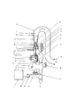
本発明を自動車エンジン排気ガスの流量測定に適用した装置の例を図1の構成図と図2以下の各部の構造詳細を参照して説明する。
自動車エンジン2の排気管21からの排気ガス流20は排気導入管31から装置1内部に入り、凝縮水などは凝縮水処理装置32に分離導入される。液体を含まない排気ガスがBBT3を経由して鉛直に配置された縦置きの測定管路10に入りベンチュリ縮流部4において最小流路断面積のスロート部5まで流れを絞られ流速を増す。通常スロートの中心に可動コァー7があって流路は環状となる。ベンチュリ管路の入り口温度は熱電対などの温度センサ41で検出され、圧力は圧力導管42から絶対圧センサ51および差圧センサ52にパージ・エァー切り換え用の電磁弁46、48とフィルタ47、49を介して常時は連結されている。
An example of an apparatus in which the present invention is applied to the flow measurement of automobile engine exhaust gas will be described with reference to the block diagram of FIG.
The
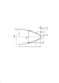
ベンチュリ管のスロート5を形成する内周側は可動コァー7の外周であるが、その径は軸方向位置により滑らかに変化するように作られており、有効流路断面積が軸方向移動距離に対して直線的に変化するよう設計してある。図2にコァー断面形状を例示してあるが、スロート部の有効断面面積はコァー断面の軸方向傾斜が30°C以上に大きくなると傾斜面に沿った流れの影響からスロート位置に応じてやや大きくなる。実験の結果をもとにコァー曲面を修正する方法を試み、結論的には図2の点線で示した単純な回転放物曲面から実線で示したように補正した曲面を得た。こうした補正した可動コァーの曲面にすることによりコァー移動距離xに対する有効スロート断面積との関係はほぼ直線関係にすることができた。補正によって顕著に見られるコァー形状の特徴はコァーの最大移動距離よりも製作されたコァーの長さが短くなり、コァーがスロート圧検出点の平面からある程度過ぎた位置で最大有効スロート断面積に達することである。
The inner peripheral side forming the throat 5 of the Venturi tube is the outer periphery of the
可変断面積ベンチュリ式排気ガス流量計では入り口、スロート部の静圧測定が極めて重要で、とくに50Pa以下の差圧測定が必要で圧力センサの選択とともに圧力導管系にも細心の留意を要する。圧力測定の応答性にも関係するが、水分などを含めた管路の清浄性を確保することは極めて重要である。図3には本装置に用いる圧力測定系を例示してある。排気ガスには粒状物質が含まれることもあり、また運転停止後に水分凝縮などを生じ圧力導管で障害となることがある。測定開始時や終了時に加圧清浄空気で圧力導管をパージして常に清浄性を保ち得るように電磁弁46、48及びフィルタ47、49を絶対圧センサ51差圧センサ52の導管系に配置する圧力測定系とした。配管50は調圧され清浄化された加圧空気のラインである。
In the variable cross-section venturi type exhaust gas flow meter, it is extremely important to measure the static pressure at the inlet and throat, and in particular, it is necessary to measure a differential pressure of 50 Pa or less. Although it is related to the responsiveness of pressure measurement, it is extremely important to ensure the cleanliness of the pipeline including moisture. FIG. 3 illustrates a pressure measurement system used in the present apparatus. The exhaust gas may contain particulate matter, and may cause water condensation after the operation is stopped, which may obstruct the pressure conduit. The
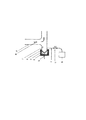
排気ガスに含まれる水分は露点以上の温度では気化状態と考えられるが、流路の管壁温度が低い場合には凝縮水を生じていることも少なくない。始動時にはエンジン側の排気管でも凝縮水が流れるので、本測定装置の入り口には液体水分が導入されるとして対応する必要がある。図4に凝縮水の蒸発装置32の具体的な構成例を示す。排気ガス導入管31の下部壁面に沿って流入する液状の水分は加熱蒸発装置32のヒーター・ブロックの蒸発面53に留まる。蒸発面は150〜200°C程度に温度センサ55の信号を基にヒータ54で加熱制御されており、普通には流入する液状水分は充分に気化できる。必要に応じては排水管56と電磁弁57を経由してドレインタンク59に排出される。ヒータ・ブロックの外側面は遮熱のために保温材58で覆われている。
The moisture contained in the exhaust gas is considered to be in a vaporized state at a temperature above the dew point, but condensed water is often generated when the tube wall temperature of the flow path is low. Condensed water also flows in the exhaust pipe on the engine side at the time of start-up, so it is necessary to cope with the fact that liquid moisture is introduced into the entrance of this measuring device. FIG. 4 shows a specific configuration example of the condensed water evaporator 32. The liquid water flowing along the lower wall surface of the exhaust
本発明の実施例を図1、図3、図4に沿って説明する。エンジン2から排出された排気ガス20はエンジン排気管21に接続されたほぼ水平に配置された排気導入管31に導入され、液状成分があるときは管壁に沿って下方の凝縮水処理装置32に分離導入され、気体成分は上方の管路からバッファー装置3(BBT)に導かれる。バッファー装置3においては排気流の脈動がシリコーンゴム薄膜の伸縮によって減衰されて排気流は平滑化されて、さらに上方に配置された排気ガス流量計1に入る。凝縮水処理装置32は図4に例示されているように下部上面が凹型になった蒸発面53を持ち、液状成分を受け止めて加熱ヒーター54で測定開始直前から運転初期には150〜200°C程度に加熱されている。この温度制御はヒータ・ブロックの中心部に配置された温度センサ信号を基に測定開始前の適当な時期から行われる。始動時などで凝縮水が多く蒸発面に溜まるのを避けるために排水導管56を通して電磁弁57を経由しオートドレイン装置の付いたタンク59から測定系外に排除できるようにしてある。
An embodiment of the present invention will be described with reference to FIGS.
排気ガス温度が例えば200°Cを超えると、バッファー装置(BBT)の冷却のための軸流ファン37、38が作動して、シリコーンゴム膜の温度上昇を防ぐことができる。ベンチュリ管路の側面には軸流ファン39が配置され、可動コァーの駆動軸8が管路を貫通する。貫通部13には軸シール部14があり、外部は冷却フイン15を設けてあり、気密を確保してしかも軸部を効果的に冷却する。とくに軸流ファン36はアクチュエータ16と貫通部13を強く冷却するように構成する。また遮熱板22を配置して高温排気ガスの管路からの熱伝達を少なくするようにしてある。
When the exhaust gas temperature exceeds 200 ° C., for example, the
測定管路10は鉛直に配置されたベンチュリ管でスロート部の断面積が中心に配置された可動コァー12の軸方向移動により可変できる構造である。ベンチュリの入り口圧力は図3のように円周40に配置された4ケの測定孔42の平均値が引き出せるように導管を構成して、電磁弁48の共通端管に連結され、常時(非通電時)には解放端からフィルタ49を経由して差圧センサ51の高圧端に連結される。同時に入り口絶対圧はフィルタを経由して差圧センサ51の入り口から分岐された配管で絶対圧センサ52に連結され測定される。ベンチュリのスロート圧力は入り口と同様にスロート断面の円周に4ケの測定孔43を配置して平均値が引き出せるようにして電磁弁46、フィルタ47を経由して差圧センサ51の低圧端に連結される。
The
ベンチュリの流量計算の温度は入り口温度が基準となるので入り口圧力測定の面から近い管内で、管径のほぼ
![]()
![]()
測定管路10の下流側はベント管18で排気ガス流は方向を逆にして適当な位置から排出管路19から測定装置の外部に排出される。下流側は圧力損失を少なくするために抵抗の少ない管路に接続することが望ましい。
The downstream side of the
本発明の排気ガス流量計はベンチュリ方式としては測定レンジが極めて広く構造的に400°C以上の排気ガス温度にも適用でき、とくに脈動影響の大きいレシプロ・エンジンのアイドリングから高速高負荷運転まで、およびガソリンエンジンからディーゼルエンジンを含めて各サイズのエンジンにまで適応できるので自動車産業における利用の可能性は絶大である。その他の産業においても流量測定を必要とする場合は多く、とくに変動を伴う流路においても広範囲の気体流量測定に広く活用可能である。 The exhaust gas flow meter of the present invention has a very wide measurement range as a venturi system and can be applied structurally to exhaust gas temperatures of 400 ° C or higher, especially from idling of reciprocating engines, which have a large pulsation effect, to high speed and high load operation, Since it can be applied to engines of various sizes including gasoline engines to diesel engines, the potential for use in the automobile industry is enormous. In other industries, there are many cases where flow measurement is required, and it can be widely used for gas flow measurement over a wide range, especially in flow paths with fluctuations.
1 可変断面積ベンチュリ式流量計
2 エンジン
3 バッファー装置(BBT)
4 ベンチュリ縮流部
5 ベンチュリ・スロート部
6 ベンチュリ・拡大部
7 可動コァー
8 コァー駆動軸
9 コァー位置検出センサ
10 測定管路
11 コァー駆動軸支持軸受
12 軸受支持支柱
13 コァー駆動軸貫通部
14 軸シール部
15 軸シール冷却ファン
16 可動コァー・アクチュエータ
17 排気ガス試料抽出プローブ
18 測定管路下流ベント管
19 排出管路
20 エンジン排気ガス流
21 エンジン排気管
22 遮熱板
31 排気ガス導入管
32 凝縮水処理装置
33 BBTゴム膜保護メッシュ
34 BBTシリコーンゴム薄膜
40 ベンチュリ入り口圧力検出部
41 ベンチュリ入り口温度センサ
42 ベンチュリ入り口圧力測定孔(4ケ所)
43 ベンチュリ・スロート部圧力測定孔(4ケ所)
44 ベンチュリ・拡大部圧力回復静圧測定孔
45 平均化圧力導管系
46 3方電磁弁
47 フィルタ
48 3方電磁弁
49 フィルタ
50 パージ・エァーライン
51 差圧センサ
52 絶対圧センサ
53 凝縮水蒸発面
54 加熱ヒータ
55 温度センサ
56 凝縮水排出導管
57 電磁弁
59 凝縮水貯留ドレインタンク
1 Venturi type flow meter with variable cross section 2 Engine 3 Buffer device (BBT)
4 Venturi contraction section 5 Venturi /
43 Venturi / throat pressure measurement holes (4 locations)
44 Venturi / enlarged part pressure recovery static
Claims (5)
Priority Applications (1)
| Application Number | Priority Date | Filing Date | Title |
|---|---|---|---|
| JP2007286489A JP5089340B2 (en) | 2007-11-02 | 2007-11-02 | Structure of variable cross-section venturi type exhaust gas flowmeter |
Applications Claiming Priority (1)
| Application Number | Priority Date | Filing Date | Title |
|---|---|---|---|
| JP2007286489A JP5089340B2 (en) | 2007-11-02 | 2007-11-02 | Structure of variable cross-section venturi type exhaust gas flowmeter |
Publications (2)
| Publication Number | Publication Date |
|---|---|
| JP2009115508A JP2009115508A (en) | 2009-05-28 |
| JP5089340B2 true JP5089340B2 (en) | 2012-12-05 |
Family
ID=40782817
Family Applications (1)
| Application Number | Title | Priority Date | Filing Date |
|---|---|---|---|
| JP2007286489A Active JP5089340B2 (en) | 2007-11-02 | 2007-11-02 | Structure of variable cross-section venturi type exhaust gas flowmeter |
Country Status (1)
| Country | Link |
|---|---|
| JP (1) | JP5089340B2 (en) |
Families Citing this family (3)
| Publication number | Priority date | Publication date | Assignee | Title |
|---|---|---|---|---|
| US8938961B2 (en) * | 2011-12-30 | 2015-01-27 | Caterpillar Inc. | EGR flow sensor for an engine |
| CN115638840A (en) * | 2022-10-19 | 2023-01-24 | 东风商用车有限公司 | Venturi tube pulsation flow correction method, device, equipment and storage medium |
| CN115683241B (en) * | 2022-10-19 | 2026-01-06 | 西安京兆电力科技有限公司 | A Big Data Analysis-Based Airflow Measurement System |
Family Cites Families (6)
| Publication number | Priority date | Publication date | Assignee | Title |
|---|---|---|---|---|
| JP2962847B2 (en) * | 1991-02-01 | 1999-10-12 | 株式会社司測研 | Variable venturi type constant flow measurement control device |
| JP3519136B2 (en) * | 1994-08-31 | 2004-04-12 | 株式会社司測研 | Variable cross-sectional area using movable venturi tube Constant flow sampling device using critical flow venturi tube |
| JPH09218062A (en) * | 1996-02-13 | 1997-08-19 | Tsukasa Sotsuken:Kk | Variable sectional area venturi type flow meter |
| JPH10311768A (en) * | 1997-05-12 | 1998-11-24 | Omron Corp | Pressure sensor and gas meter |
| JPH10318810A (en) * | 1997-05-16 | 1998-12-04 | Toyota Motor Corp | Exhaust gas flow measurement device |
| JP4247870B2 (en) * | 2002-03-11 | 2009-04-02 | 株式会社司測研 | Surge tube structure |
-
2007
- 2007-11-02 JP JP2007286489A patent/JP5089340B2/en active Active
Also Published As
| Publication number | Publication date |
|---|---|
| JP2009115508A (en) | 2009-05-28 |
Similar Documents
| Publication | Publication Date | Title |
|---|---|---|
| CN103492873B (en) | Sensor device for detecting a parameter of a flowing fluid medium | |
| JP5089340B2 (en) | Structure of variable cross-section venturi type exhaust gas flowmeter | |
| WO2019109648A1 (en) | Simple chamber for formaldehyde or voc release test and pretreatment | |
| US20120024507A1 (en) | Muffler with a built-in heat exchanger | |
| US20130133631A1 (en) | System to measure parameters of a particulate laden flow | |
| US6485537B2 (en) | Steam separator and valve with downward inlet | |
| US20110061831A1 (en) | System and method for non-contact sensing to minimize leakage between process streams in an air preheater | |
| JP2006162417A (en) | Total pressure/static pressure measuring venturi system flow measuring device | |
| US8371162B2 (en) | Apparatus and method for testing a compressor | |
| CN112833662A (en) | Temperature regulators and semiconductor processing equipment | |
| US11067483B2 (en) | Hybrid cooler/dryer and method therefor | |
| US10809165B2 (en) | Pressure reduction system and method for reducing the pressure of high pressure aerosols | |
| JP2016503138A (en) | Coolant supply flange for parts to be cooled and parts provided with such flanges | |
| CN112945650B (en) | Flue gas sampling device and sampling method | |
| JP5787657B2 (en) | Steam pipe structure | |
| US10197177B2 (en) | Compressor thermal valve unit to route lubricant used in a compressor | |
| JP5888196B2 (en) | EGR cooler | |
| CN205843923U (en) | A kind of full plate-fin heat exchanger fluid resistance feature measurement test specimen | |
| CN120740782B (en) | Temperature sensor for controlling opening degree of valve of air-inducing temperature-controlling system | |
| CN110681268A (en) | Dynamic detection system and method for contact angle of gas purification membrane | |
| CN223724737U (en) | Novel methanol fuel double-wall conveying pipeline | |
| CN105823618B (en) | Full plate-fin heat exchanger fluid resistance feature measurement test specimen | |
| CN114585838A (en) | One-way check valve for vacuum system | |
| JP2013076626A (en) | Flow rate sensor, and particulate filter diagnostic apparatus for internal combustion engine | |
| CN117109835B (en) | Monitoring device of water cooler in polycrystalline silicon preparation system |
Legal Events
| Date | Code | Title | Description |
|---|---|---|---|
| A621 | Written request for application examination |
Free format text: JAPANESE INTERMEDIATE CODE: A621 Effective date: 20100924 |
|
| A977 | Report on retrieval |
Free format text: JAPANESE INTERMEDIATE CODE: A971007 Effective date: 20120425 |
|
| A131 | Notification of reasons for refusal |
Free format text: JAPANESE INTERMEDIATE CODE: A131 Effective date: 20120627 |
|
| A521 | Request for written amendment filed |
Free format text: JAPANESE INTERMEDIATE CODE: A523 Effective date: 20120827 |
|
| TRDD | Decision of grant or rejection written | ||
| A01 | Written decision to grant a patent or to grant a registration (utility model) |
Free format text: JAPANESE INTERMEDIATE CODE: A01 Effective date: 20120911 |
|
| A01 | Written decision to grant a patent or to grant a registration (utility model) |
Free format text: JAPANESE INTERMEDIATE CODE: A01 |
|
| A61 | First payment of annual fees (during grant procedure) |
Free format text: JAPANESE INTERMEDIATE CODE: A61 Effective date: 20120911 |
|
| FPAY | Renewal fee payment (event date is renewal date of database) |
Free format text: PAYMENT UNTIL: 20150921 Year of fee payment: 3 |
|
| R150 | Certificate of patent or registration of utility model |
Ref document number: 5089340 Country of ref document: JP Free format text: JAPANESE INTERMEDIATE CODE: R150 Free format text: JAPANESE INTERMEDIATE CODE: R150 |
|
| R250 | Receipt of annual fees |
Free format text: JAPANESE INTERMEDIATE CODE: R250 |
|
| R250 | Receipt of annual fees |
Free format text: JAPANESE INTERMEDIATE CODE: R250 |
|
| R250 | Receipt of annual fees |
Free format text: JAPANESE INTERMEDIATE CODE: R250 |
|
| R250 | Receipt of annual fees |
Free format text: JAPANESE INTERMEDIATE CODE: R250 |
|
| R250 | Receipt of annual fees |
Free format text: JAPANESE INTERMEDIATE CODE: R250 |
|
| R250 | Receipt of annual fees |
Free format text: JAPANESE INTERMEDIATE CODE: R250 |
|
| R250 | Receipt of annual fees |
Free format text: JAPANESE INTERMEDIATE CODE: R250 |
|
| R250 | Receipt of annual fees |
Free format text: JAPANESE INTERMEDIATE CODE: R250 |
|
| R250 | Receipt of annual fees |
Free format text: JAPANESE INTERMEDIATE CODE: R250 |
|
| R250 | Receipt of annual fees |
Free format text: JAPANESE INTERMEDIATE CODE: R250 |
|
| R250 | Receipt of annual fees |
Free format text: JAPANESE INTERMEDIATE CODE: R250 |