JP5089169B2 - Structural / biological implant systems - Google Patents
Structural / biological implant systems Download PDFInfo
- Publication number
- JP5089169B2 JP5089169B2 JP2006533779A JP2006533779A JP5089169B2 JP 5089169 B2 JP5089169 B2 JP 5089169B2 JP 2006533779 A JP2006533779 A JP 2006533779A JP 2006533779 A JP2006533779 A JP 2006533779A JP 5089169 B2 JP5089169 B2 JP 5089169B2
- Authority
- JP
- Japan
- Prior art keywords
- bone
- implant
- osteotropic
- osteosynthesis
- stage
- Prior art date
- Legal status (The legal status is an assumption and is not a legal conclusion. Google has not performed a legal analysis and makes no representation as to the accuracy of the status listed.)
- Expired - Fee Related
Links
Images


Classifications
-
- A—HUMAN NECESSITIES
- A61—MEDICAL OR VETERINARY SCIENCE; HYGIENE
- A61B—DIAGNOSIS; SURGERY; IDENTIFICATION
- A61B17/00—Surgical instruments, devices or methods, e.g. tourniquets
- A61B17/56—Surgical instruments or methods for treatment of bones or joints; Devices specially adapted therefor
- A61B17/58—Surgical instruments or methods for treatment of bones or joints; Devices specially adapted therefor for osteosynthesis, e.g. bone plates, screws, setting implements or the like
- A61B17/68—Internal fixation devices, including fasteners and spinal fixators, even if a part thereof projects from the skin
-
- A—HUMAN NECESSITIES
- A61—MEDICAL OR VETERINARY SCIENCE; HYGIENE
- A61C—DENTISTRY; APPARATUS OR METHODS FOR ORAL OR DENTAL HYGIENE
- A61C8/00—Means to be fixed to the jaw-bone for consolidating natural teeth or for fixing dental prostheses thereon; Dental implants; Implanting tools
- A61C8/0003—Not used, see subgroups
- A61C8/0004—Consolidating natural teeth
- A61C8/0006—Periodontal tissue or bone regeneration
-
- A—HUMAN NECESSITIES
- A61—MEDICAL OR VETERINARY SCIENCE; HYGIENE
- A61L—METHODS OR APPARATUS FOR STERILISING MATERIALS OR OBJECTS IN GENERAL; DISINFECTION, STERILISATION OR DEODORISATION OF AIR; CHEMICAL ASPECTS OF BANDAGES, DRESSINGS, ABSORBENT PADS OR SURGICAL ARTICLES; MATERIALS FOR BANDAGES, DRESSINGS, ABSORBENT PADS OR SURGICAL ARTICLES
- A61L27/00—Materials for grafts or prostheses or for coating grafts or prostheses
- A61L27/28—Materials for coating prostheses
- A61L27/30—Inorganic materials
- A61L27/32—Phosphorus-containing materials, e.g. apatite
-
- A—HUMAN NECESSITIES
- A61—MEDICAL OR VETERINARY SCIENCE; HYGIENE
- A61L—METHODS OR APPARATUS FOR STERILISING MATERIALS OR OBJECTS IN GENERAL; DISINFECTION, STERILISATION OR DEODORISATION OF AIR; CHEMICAL ASPECTS OF BANDAGES, DRESSINGS, ABSORBENT PADS OR SURGICAL ARTICLES; MATERIALS FOR BANDAGES, DRESSINGS, ABSORBENT PADS OR SURGICAL ARTICLES
- A61L27/00—Materials for grafts or prostheses or for coating grafts or prostheses
- A61L27/50—Materials characterised by their function or physical properties, e.g. injectable or lubricating compositions, shape-memory materials, surface modified materials
- A61L27/54—Biologically active materials, e.g. therapeutic substances
-
- A—HUMAN NECESSITIES
- A61—MEDICAL OR VETERINARY SCIENCE; HYGIENE
- A61L—METHODS OR APPARATUS FOR STERILISING MATERIALS OR OBJECTS IN GENERAL; DISINFECTION, STERILISATION OR DEODORISATION OF AIR; CHEMICAL ASPECTS OF BANDAGES, DRESSINGS, ABSORBENT PADS OR SURGICAL ARTICLES; MATERIALS FOR BANDAGES, DRESSINGS, ABSORBENT PADS OR SURGICAL ARTICLES
- A61L27/00—Materials for grafts or prostheses or for coating grafts or prostheses
- A61L27/50—Materials characterised by their function or physical properties, e.g. injectable or lubricating compositions, shape-memory materials, surface modified materials
- A61L27/56—Porous materials, e.g. foams or sponges
-
- A—HUMAN NECESSITIES
- A61—MEDICAL OR VETERINARY SCIENCE; HYGIENE
- A61L—METHODS OR APPARATUS FOR STERILISING MATERIALS OR OBJECTS IN GENERAL; DISINFECTION, STERILISATION OR DEODORISATION OF AIR; CHEMICAL ASPECTS OF BANDAGES, DRESSINGS, ABSORBENT PADS OR SURGICAL ARTICLES; MATERIALS FOR BANDAGES, DRESSINGS, ABSORBENT PADS OR SURGICAL ARTICLES
- A61L27/00—Materials for grafts or prostheses or for coating grafts or prostheses
- A61L27/50—Materials characterised by their function or physical properties, e.g. injectable or lubricating compositions, shape-memory materials, surface modified materials
- A61L27/58—Materials at least partially resorbable by the body
-
- A—HUMAN NECESSITIES
- A61—MEDICAL OR VETERINARY SCIENCE; HYGIENE
- A61B—DIAGNOSIS; SURGERY; IDENTIFICATION
- A61B17/00—Surgical instruments, devices or methods, e.g. tourniquets
- A61B17/56—Surgical instruments or methods for treatment of bones or joints; Devices specially adapted therefor
- A61B17/58—Surgical instruments or methods for treatment of bones or joints; Devices specially adapted therefor for osteosynthesis, e.g. bone plates, screws, setting implements or the like
- A61B17/68—Internal fixation devices, including fasteners and spinal fixators, even if a part thereof projects from the skin
- A61B17/80—Cortical plates, i.e. bone plates; Instruments for holding or positioning cortical plates, or for compressing bones attached to cortical plates
-
- A—HUMAN NECESSITIES
- A61—MEDICAL OR VETERINARY SCIENCE; HYGIENE
- A61L—METHODS OR APPARATUS FOR STERILISING MATERIALS OR OBJECTS IN GENERAL; DISINFECTION, STERILISATION OR DEODORISATION OF AIR; CHEMICAL ASPECTS OF BANDAGES, DRESSINGS, ABSORBENT PADS OR SURGICAL ARTICLES; MATERIALS FOR BANDAGES, DRESSINGS, ABSORBENT PADS OR SURGICAL ARTICLES
- A61L2300/00—Biologically active materials used in bandages, wound dressings, absorbent pads or medical devices
- A61L2300/20—Biologically active materials used in bandages, wound dressings, absorbent pads or medical devices containing or releasing organic materials
- A61L2300/252—Polypeptides, proteins, e.g. glycoproteins, lipoproteins, cytokines
-
- A—HUMAN NECESSITIES
- A61—MEDICAL OR VETERINARY SCIENCE; HYGIENE
- A61L—METHODS OR APPARATUS FOR STERILISING MATERIALS OR OBJECTS IN GENERAL; DISINFECTION, STERILISATION OR DEODORISATION OF AIR; CHEMICAL ASPECTS OF BANDAGES, DRESSINGS, ABSORBENT PADS OR SURGICAL ARTICLES; MATERIALS FOR BANDAGES, DRESSINGS, ABSORBENT PADS OR SURGICAL ARTICLES
- A61L2300/00—Biologically active materials used in bandages, wound dressings, absorbent pads or medical devices
- A61L2300/20—Biologically active materials used in bandages, wound dressings, absorbent pads or medical devices containing or releasing organic materials
- A61L2300/258—Genetic materials, DNA, RNA, genes, vectors, e.g. plasmids
-
- A—HUMAN NECESSITIES
- A61—MEDICAL OR VETERINARY SCIENCE; HYGIENE
- A61L—METHODS OR APPARATUS FOR STERILISING MATERIALS OR OBJECTS IN GENERAL; DISINFECTION, STERILISATION OR DEODORISATION OF AIR; CHEMICAL ASPECTS OF BANDAGES, DRESSINGS, ABSORBENT PADS OR SURGICAL ARTICLES; MATERIALS FOR BANDAGES, DRESSINGS, ABSORBENT PADS OR SURGICAL ARTICLES
- A61L2300/00—Biologically active materials used in bandages, wound dressings, absorbent pads or medical devices
- A61L2300/40—Biologically active materials used in bandages, wound dressings, absorbent pads or medical devices characterised by a specific therapeutic activity or mode of action
- A61L2300/412—Tissue-regenerating or healing or proliferative agents
-
- A—HUMAN NECESSITIES
- A61—MEDICAL OR VETERINARY SCIENCE; HYGIENE
- A61L—METHODS OR APPARATUS FOR STERILISING MATERIALS OR OBJECTS IN GENERAL; DISINFECTION, STERILISATION OR DEODORISATION OF AIR; CHEMICAL ASPECTS OF BANDAGES, DRESSINGS, ABSORBENT PADS OR SURGICAL ARTICLES; MATERIALS FOR BANDAGES, DRESSINGS, ABSORBENT PADS OR SURGICAL ARTICLES
- A61L2430/00—Materials or treatment for tissue regeneration
- A61L2430/02—Materials or treatment for tissue regeneration for reconstruction of bones; weight-bearing implants
Description
連邦後援の研究または開発に関する報告
本発明は、アメリカ国立歯科顔面科研究所の交付番号DE14187の下、政府支援により行われた。政府は、本発明において一定の権利を有する。
REPORT ON FEDERALLY SPONSORED RESEARCH OR DEVELOPMENT This invention was made with government support under grant number DE14187 of the National Institute of Dental Facials. The government has certain rights in the invention.
本発明は一般に、構造的/生物学的インプラントならびに自家骨、自己細胞または改変細胞、石灰化材料、脱灰骨基質、アルギン酸塩、コラーゲン材料、材料として有用な物品を含み得るインプラント材料を使用する、または使用しない骨成長を促進するための方法に関する。 The present invention generally uses structural / biological implants as well as implant materials that may include autologous bone, autologous or modified cells, mineralized materials, demineralized bone matrix, alginate, collagen materials, articles useful as materials. Or to a method for promoting bone growth that is not used.
頭蓋顔面外科および整形外科分野において、骨量不足の問題は、十分に認識されている。例えば、歯科インプラントは、残存骨内の移植床内へ、そのインプラントの形状に応じてはめ込む必要がある。標準的インプラントは、安定性に必要とされる密着適合性と骨内へ埋入経路を考えて、また、線維組織内へ入れる一方で、造骨能のある細胞による移植部位の選択的再増殖が促進されるように、円筒状または僅かに先細りした形状を有する。臨床症例では、標準的な骨内歯科インプラントの埋入にとって、骨高および/または骨幅が不十分である割合が高い。 In the craniofacial and orthopedic field, the problem of bone loss is well recognized. For example, a dental implant needs to be fitted into the graft bed in the remaining bone depending on the shape of the implant. Standard implants are designed for close recombination required for stability and the path of implantation into the bone, and into the fibrous tissue, while selective re-growth of the transplant site with osteogenic cells Have a cylindrical shape or a slightly tapered shape. In clinical cases, a high percentage of bone height and / or bone width is insufficient for the placement of standard intraosseous dental implants.
欠損歯の代わりとなる歯科インプラントは、最適条件下で配置された場合、臨床実践において、90〜95%成功している。これらの条件には、患者の全身的健康状態が良好であること、インプラント部位において骨質が十分であること、骨容量が十分であることおよび骨形状が十分であることが含まれる。残念ながら、歯が欠損すると、骨は再吸収されてしまう。この連続的骨欠損により、前記箇所のかなりの部分の骨容量は、インプラント埋入から利益を得るには不十分になってしまう。骨移植は、現在、骨の隆線の高さと幅を増やし、それによって顎顔面の骨容量を増やすための標準的方法である。現在の骨移植法には、肋骨、寛骨または脚骨または顎の骨塊などの位置に広範囲なドナー部位を必要とする有痛性観血的な時には危険な、または長時間の操作が含まれる。 Dental implants that replace missing teeth are 90-95% successful in clinical practice when placed under optimal conditions. These conditions include good general health of the patient, sufficient bone quality at the implant site, sufficient bone volume and sufficient bone shape. Unfortunately, missing teeth result in bone resorption. With this continuous bone defect, the bone volume of a significant portion of the site becomes insufficient to benefit from implant placement. Bone grafting is currently the standard method for increasing the height and width of bone ridges, thereby increasing the maxillofacial bone volume. Current bone grafting methods involve dangerous or prolonged manipulations that are painful and open, requiring extensive donor sites in locations such as ribs, hips or leg bones or jaw bone masses It is.
標準的なインプラント埋入が不可能な無歯領域における骨容量を補うための組織工学的方法は、鋭意開発中である。これらの方法には、足場、成長因子および造骨能のある細胞の使用が含まれる。しかし、現在のところ、代謝物および生成物の細胞外輸送;情報伝達部分の寿命と有効な拡散距離と提示のタイミング;および適切に分布した血管によって提供される多数の支持機能などの問題により、移植できる材料の大きさ(特に厚さ)には、かなりの制限がある。したがって、例えば、多くの組織工学製品は、2ミリメートルから3ミリメートルの厚さに制限され、1つの外科手術工程において臨床的に意味のある大きさには恐らく不十分であろう。 Tissue engineering methods for supplementing bone volume in edentulous areas where standard implant placement is not possible are under intense development. These methods include the use of scaffolds, growth factors and osteogenic cells. However, due to issues such as the extracellular transport of metabolites and products; the lifetime of the signaling moiety and the effective diffusion distance and timing of presentation; and the numerous support functions provided by appropriately distributed blood vessels, There are considerable limitations on the size (especially thickness) of the material that can be implanted. Thus, for example, many tissue engineering products are limited to a thickness of 2 to 3 millimeters and are probably insufficient for a clinically meaningful size in one surgical process.
簡略的に述べると、好ましい形態における本発明は、構造上の目的でインプラント周囲の骨成長を促進するために、自己骨インプラント、細胞および/または治療薬送達を用いるか、または用いない構造的/生物学的インプラントおよびその使用法である。本発明は、幾つかの形態において、自己骨インプラントによって用いることもできる。 Briefly, the present invention in a preferred form is structured / not used with or without autologous bone implants, cellular and / or therapeutic drug delivery to promote bone growth around the implant for structural purposes. Biological implants and methods of use thereof. The present invention can also be used with self-bone implants in several forms.
本発明の他の実施形態は、残存する下顎骨の高さが、標準的歯科インプラントの埋入には不十分である場合に用いられる骨増加歯科移植システムである。 Another embodiment of the present invention is a bone augmentation dental implant system used when the remaining mandible height is insufficient for standard dental implant placement.
一般に、インプラントの一部を残存骨内に固定し、前記インプラントの残部は、残存骨の外側へ延在する。インプラントの延在部または露出部は、種々の付加されたおよび/または一体形成された機械的保持性要素および安定性要素の少なくとも1つを含む外形または立体構造を含み得る骨結合表面を有する。新骨の成長は、前記インプラントの露出部分周囲に生じ、それにより、患者の骨の高さと容量が増加する。 Generally, a portion of the implant is fixed in the remaining bone, and the remaining portion of the implant extends outside the remaining bone. The extension or exposed portion of the implant has an osteosynthesis surface that may include an outer shape or a three-dimensional structure that includes at least one of a variety of added and / or integrally formed mechanical retention elements and stability elements. New bone growth occurs around the exposed portion of the implant, thereby increasing the height and volume of the patient's bone.
インプラントの露出部分周囲の新骨成長を誘導、促進または増強させるために、インプラントと結合させて骨誘導性、骨先導性、オステオトロピックおよび/または造骨性であり得る生物学的材料(本明細書において、オステオトロピック材料と称される)が使用できる。 Biological materials that may be osteoinductive, bone-leading, osteotropic and / or osteogenic in combination with the implant to induce, promote or enhance new bone growth around the exposed portion of the implant (Referred to as osteotropic material).
本明細書において、アンジオトロピック性材料と称される化学的薬物、蛋白質および成長因子をコードする核酸などの血管形成材料の使用により、血管の増大および/または増強が達成できる。これらのオステオトロピック/アンジオトロピック材料としては、限定はしないが、骨または血管内皮の再生を支持および指示し、さらにしばしば成長因子および前駆体細胞を組み込み得る先導的および/または誘導的足場が挙げられる。前記オステオトロピック/アンジオトロピック材料は、骨細胞の接着および成長に直ちに利用できる表面を提供する。さらに、これらの材料を、適切な骨誘導因子と組み合わせて、骨形成を推進する環境条件を提供することができる。 By using an angiogenic material such as nucleic acids encoding chemical drugs, proteins and growth factors referred to herein as angiotropic materials, an increase and / or enhancement of blood vessels can be achieved. These osteotropic / angiotropic materials include, but are not limited to, leading and / or inductive scaffolds that support and direct bone or vascular endothelium regeneration and can often incorporate growth factors and precursor cells. . The osteotropic / angiotropic material provides a surface that is readily available for bone cell adhesion and growth. In addition, these materials can be combined with appropriate osteoinductive factors to provide environmental conditions that promote bone formation.
このように、残存の骨容量内にインプラントをはめ込むのではなく、インプラントの露出部の内部および周囲に、新たな骨容量と支持血管が成長し、位置の安定した、生体に統合されたインプラントが提供される。また、インプラント構造によるオステオトロピック/アンジオトロピック材料の一貫した位置保持性と安定化は、インプラント構造に対するオステオトロピック/アンジオトロピック材料の密着適合性によっても達成できる。インプラントは、組織工学的方法によって使用が受け入れられる。例えば、これには、未分化幹細胞、骨または関節の前駆体細胞または分化細胞の足場材料への移植が含まれる。また、これには、局所細胞または骨欠損部位において、足場材料内へ腐骨化、または移植した細胞からの成長因子発現を誘導するための形質移入ベクター療法も含まれる。 In this way, instead of fitting the implant into the remaining bone volume, a new bone volume and supporting blood vessels grow in and around the exposed portion of the implant, resulting in a stable and integrated living body implant. Provided. Consistent position retention and stabilization of the osteotropic / angiotropic material by the implant structure can also be achieved by the close fit of the osteotropic / angiotropic material to the implant structure. The implant is accepted for use by tissue engineering methods. For example, this includes transplantation of undifferentiated stem cells, bone or joint precursor cells or differentiated cells into the scaffold material. This also includes transfection vector therapy to induce ossification into the scaffold material or growth factor expression from the transplanted cells at the local cell or bone defect site.
本発明は、既存の移植システムにとって、骨の高さおよび/または骨の形状が不十分である場所におけるインプラントの使用を可能にする。例えば、従来のインプラントは、典型的に10ミリメートルから12ミリメートルの骨の高さを必要とする。しかし、本発明のインプラントでは、治療開始時に必要とされる高さは、僅か4ミリメートルから6ミリメートルである。治療中に、1つ以上の外科手術操作において、インプラントの周囲にさらに2ミリメートルから6ミリメートルの骨が成長できる。 The present invention allows the use of implants where bone height and / or bone shape is insufficient for existing implant systems. For example, conventional implants typically require bone heights of 10 to 12 millimeters. However, with the implant of the present invention, the height required at the start of treatment is only 4 to 6 millimeters. During treatment, an additional 2 to 6 millimeters of bone can grow around the implant in one or more surgical operations.
前記インプラントの部分は、再吸収性または非再吸収性材料から作製でき、骨がインプラントと一体化して成長してから、最適な位置安定性が得られるように形状化または構成できる。また、再吸収性または非再吸収性骨内歯科インプラントは、高さの減少した骨と共に用いられる組織工学的材料によって、および/または部分的骨形成を可能にするためにも利用できる。 The portion of the implant can be made from a resorbable or non-resorbable material and can be shaped or configured for optimal positional stability after the bone grows integrally with the implant. Resorbable or non-resorbable intraosseous dental implants can also be utilized by tissue engineering materials used with reduced height bone and / or to allow partial bone formation.
一般に、本発明の材料は、代替として本明細書に開示された任意の適切な成分を含んでなるか、それから成り立つか、または、本質的に成り立つように配合できる。本発明の材料は、さらにまたは代替として先行技術の組成物において使用された、または他の場合には、その機能および/または本発明の目的の達成にとって必ずしも必要ではない任意の成分、材料、要素、アジュバントまたは種を欠くように、または実質的にそれらが無いように配合できる。 In general, the materials of the present invention can alternatively be formulated to comprise, consist of, or consist essentially of any suitable component disclosed herein. The materials of the present invention may additionally or alternatively be used in any prior art composition or otherwise any component, material, element that is not necessarily required for its function and / or achievement of the objects of the present invention. Can be formulated to lack an adjuvant or species, or be substantially free of them.
本発明の他の目的および利点は、添付の図面を参考にして以下の詳細な説明から、通常の当業者にとって明らかとなろう。 Other objects and advantages of the present invention will become apparent to those of ordinary skill in the art from the following detailed description with reference to the accompanying drawings.
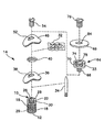
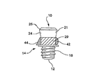
図1に図示されるように、本発明の一実施形態におけるインプラントは、冠側端10と頂端12との間に延在する中心軸(示していない)を有する。インプラントは、固定部分18の付いた一次インプラント部分16を有する段階Iのアセンブリ10を含む。固定部分18は、中心軸に対し、実質的に軸対称とすればよい。固定部分18は、外面を有する。一実施形態において、固定部分18の外面は、その上に螺旋状に設けられたねじ山20などの固定手段を有する。前記ねじ山は、最小の間隔、例えば、1mm未満を有し、残存骨に対する係合および適合性を最適なものとするため、セルフタッピングにすると有利である。残存骨に対する固定部分18の固定を助けるため、固定部分18の外面に、他の固定手段を配置できる。前記固定部分18は、長さを例えば、約3mmと約6mmとの間とすればよい。一次インプラント部分16は、さらに長さが約2mmの経粘膜部分22もまた有すればよい。前記経粘膜部分22は、一次インプラント部分16と一体形成されていてもよいし、一次インプラント部分16から分離可能な別個の部品であってもよい。
As shown in FIG. 1, the implant in one embodiment of the present invention has a central axis (not shown) extending between the
前記経粘膜部分22は、図1に図示されたように、ねじ穴穿孔26などの接続面を有し得る。前記ねじ穴の壁は、スロット28または当業界に周知の他の器具係合面を規定し得る。
The
図6Dに示された本発明の他の実施形態において、一次インプラント部分16の経粘膜部分は、研磨仕上げのカラー24を有し得る。研磨仕上げのカラーは、軸方向長さを、凡そ2mmとすることができ、終末ライン25で終端させる。終末ライン25は、冠側端10と頂端12との間に延在する中心軸に対して例えば、ある角度に向ければよい。
In another embodiment of the invention shown in FIG. 6D, the transmucosal portion of the
幾つかの実施形態において、別個の経粘膜部分を有することが望ましい。例えば、複数の段階が用いられる場合、一次構造インプラントは、別個の経粘膜部分(示していない)を有し、研磨仕上げのカラーは含んでも、含まなくてもよい。 In some embodiments, it is desirable to have a separate transmucosal portion. For example, if multiple stages are used, the primary structure implant has a separate transmucosal portion (not shown) and may or may not include a polished collar.
経粘膜部分は、中心軸に対して、軸方向に対称である必要はない。本発明の幾つかの実施形態において(示していない)、経粘膜部分は、美観的、生体的またはさらに機械的利益を提供するためにデザインされた横断面形状を有し得る。このような非対称的形状は、例えば、美観的価値または補綴機能の機械的安定性を提供すると考えられる歯根型とすればよい。 The transmucosal portion need not be symmetrical in the axial direction with respect to the central axis. In some embodiments of the present invention (not shown), the transmucosal portion may have a cross-sectional shape designed to provide aesthetic, biological or even mechanical benefits. Such an asymmetric shape may be, for example, a root type that is believed to provide aesthetic value or mechanical stability of the prosthetic function.
インプラントの骨結合部分30は、経粘膜部分22の先端に配置される。経粘膜部分22および骨組み部分30は、オステオトロピック/アンジオトロピック材料32の装着および配置を補助するために、構成および/または適合化しておけばよい。例えば、経粘膜部分22および骨結合部分32は、経粘膜部分22および骨結合部分30上にオステオトロピック/アンジオトロピック材料32を、位置合わせし、通過させ易くするように、オステオトロピック/アンジオトロピック材料32における開口部に相補的な形状を有するようにすればよい。
The
図1を参照すると、一次インプラント部分16は、長さが、例えば、約2mmである骨結合部分30を有する。骨結合部分30の大きさおよび位置は当然のこと、その部位の骨結合能に依って変化する。骨結合能は、例えば、インプラントに結合したオステオトロピック/アンジオトロピック材料32(1つまたは複数)のタイプならびに、移植部位の位置、形態および生理に依って変化し得る。骨結合部分30は、典型的に経粘膜部分22と固定部分18との間に配置される。しかし、骨結合部分30を他の位置に配置してもよい。例えば、骨結合部分30を、一次挿入部分16の頂端12に配置できる。また、当然のこと、インプラントには、複数の骨結合部分が、存在し得る(示していない)。
Referring to FIG. 1, the
いずれの実施形態でも骨結合部分に、例えば、生体活性であり、迅速な骨結合またはしっかりとなじむような新骨の成長を促進するようにデザインされている一方、新たに成長した骨に対する安定性および保持性を高めることができるように構成されている表面があるようにすればよい。前記表面の生体活性は、例えば、骨組み部分の化学的な表面特性を修飾することによって達成できる。例えば、骨結合部分の表面をコーティングするためにリン酸カルシウムを使用できる。 In either embodiment, the osteosynthesis portion is designed to promote the growth of new bone that is, for example, bioactive, rapid osteosynthesis or tight fit, while being stable to newly grown bone In addition, the surface may be configured so as to enhance the retention. The bioactivity of the surface can be achieved, for example, by modifying the chemical surface properties of the framework portion. For example, calcium phosphate can be used to coat the surface of the osteosynthesis.
骨結合部分30の外部の形状は、中心軸に対して、軸方向に対称である必要はない。骨結合部分30は、軸の傾斜またはねじれ負荷に抵抗性があるか、および/または増強された骨結合を提供するようにデザインされた、例えば、任意の数の突起、凹凸、キャビティ、エッチング/または他の特徴を有し得る。骨結合部分30は、所与の骨結合部分30の長さに対して、保持特性および安定性特性の増大を達成させるために、ある程度形状化または構成することができる。例えば、冠側端10から頂端12方向へと骨結合部分の直径が増加する逆先細り形状(示していない)を使用すると、この形状のくさび作用によって、インプラントを新たに形成された骨内に止めることができる。また、骨結合部分30は、骨が突起の周囲に形成される際に、インプラントを安定化させるように働く突起(示していない)を有することもできる。
The external shape of the
骨結合部分29は、構成領域の周囲に骨が成長する際に、機械的支持を提供することによって、移植片の位置安定性が増すように、全体として、または部分として構成できる。例えば、骨結合部分29は、図5Aに示されたような卵型42、または図5Dに示されたようなアンダーカット形44を有し得る。
The
また、骨結合部分は、骨芽細胞になって骨形成を誘導する前駆体細胞の分化や増殖に関連する内因性または外因性高分子を取り込み、かつ放出を持続する能力を有する再吸収性または非再吸収性多孔性表面を組み込むこともできる。例えば、この表面は、薬物、蛋白質または遺伝物質のための担体として使用できる。本発明の一実施形態において、骨結合部分の表面は、移植部位の直に隣接した皮質骨形成への前段階としての軟骨内骨形成を誘導する薬物または生体分子を担持できる。 Alternatively, the bone-binding portion is resorbable or capable of taking up endogenous or exogenous macromolecules associated with the differentiation and proliferation of precursor cells that become osteoblasts and induce bone formation and have sustained release. Non-resorbable porous surfaces can also be incorporated. For example, the surface can be used as a carrier for drugs, proteins or genetic material. In one embodiment of the invention, the surface of the bone attachment portion can carry a drug or biomolecule that induces endochondral bone formation as a pre-stage to cortical bone formation immediately adjacent to the implantation site.
さらに冠側端10に取り外し可能に取り付けられているエキステンダー34があってもよい。前記エキステンダーは、例えば、ねじ穴26との係合が可能になるように処理されたねじ山を有するようにすればよい。取り付けられたエキステンダー34は、オステオトロピック/アンジオトロピック材料32とエキステンダー34との係合が可能になるように冠側部方向へ軸平行に延在している。このような係合によって、外科手術をする場合、経粘膜部分22と骨結合部分30上にオステオトロピック/アンジオトロピック材料32を精確にかつ制御しつつ配置することが可能になる。
There may also be an
固定部分18の最外表面から、横方向外向きに延在する予備安定材36が存在してもよい。例えば、前記予備安定材36は、約2mm外向きに延在し得る。前記予備安定材36は、例えば、埋め込まれた固定部分18の周囲にあって座ぐりのために加工された骨の座ぐり領域と接触する。前記予備安定材36は、インプラントに対する横方向安定性を提供すると共に、予備安定材36の周囲に新骨が形成された後、保持安定性を提供するように働き得る。
There may be a pre-stabilizer 36 extending laterally outward from the outermost surface of the fixed
本発明の一実施形態において、前記予備安定材36は、固定部分18が十分な深さ、例えば、約4mmから約6mmまで骨に埋め込まれる場合、なくしてもよい分離可能部品である。この実施形態において、前記予備安定材36は、内部を螺合させておけばよい中心開口部38を有する。前記中心開口部38は、例えば、骨の上方に延在する最初の移植片の部分に螺合させておけばよい。前記予備安定材36は、予備安定材ナット40により、骨に対して固定できる。
In one embodiment of the invention, the pre-stabilizer 36 is a separable part that may be eliminated if the anchoring
図5Aおよび6Aに図示された本発明の他の実施形態において、予備安定材35は、原挿入部分16の一体化部品である。この実施形態において、予備安定材35は、原挿入部分16に永久的に取り付けられているか、または原挿入部分16と共に形成される。前記予備安定材35は、使用時、インプラントが埋め込まれる際に骨と接触する。
In another embodiment of the invention illustrated in FIGS. 5A and 6A, the pre-stabilizer 35 is an integral part of the
また、予備安定材は、一次インプラント部分16の周囲に予備安定材が回転することができるようにインプラントに固定することもできる。予備安定材35が軸方向には固定されているが、一次インプラント部分16の周囲を回転できるように、予備安定材35の縁(示していない)が係合する一次インプラント部分16に形成された外周溝があってもよい。
The pre-stabilizer can also be secured to the implant so that the pre-stabilizer can rotate around the
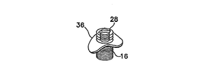
本発明の一実施形態において、図1に示されたオステオトロピック/アンジオトロピック材料安定化材46と称される第2の安定材を、構造的インプラントに取り付けてもよい。他の実施形態において、図8Aおよび8Bに図示されているように、オステオトロピック/アンジオトロピック材料安定化材47は、1つ以上の切抜き50および/または突起(示していない)を有する湾曲した、または弓形の平面形態を有し得る。これらの切抜き50は、生物学的材料の安定化、細胞集合および/または血管形成の増強を提供する。オステオトロピック/アンジオトロピック材料安定化材46は、例えば、一次インプラント部分16上のねじ山に係合させるために、図1に図示したねじ切り開口部52を有し得る。
In one embodiment of the invention, a second stabilizer, referred to as the osteotropic /
オステオトロピック/アンジオトロピック材料安定化材46は、図2Dに図示されたように一次インプラント部分16の冠側端10上に配置でき、穿孔26などの接続面に係合し得る段階Iのカバーねじ54によって正しく固定することができる。あるいは、オステオトロピック/アンジオトロピック材料安定化材は、この安定化材が、カバーねじの部分から横方向外向きに延在するように、カバーねじと一体化して形成できる(示していない)。例えば、カバーねじの頭部は、中心軸の周囲に放射状外向きに延在する部分を有し得る。
An osteotropic /
いずれの実施形態においても、オステオトロピック/アンジオトロピック材料安定化材は、再吸収性の有機および/または無機材料、または金属およびセラミックなどの非再吸収性材料など、移植業界に公知の任意の好適な材料から形成できる。 In any embodiment, the osteotropic / angiotropic material stabilizer is any suitable known to the implantation industry, such as resorbable organic and / or inorganic materials, or non-resorbable materials such as metals and ceramics. Can be formed from any material.
図1に示されるように、オステオトロピック/アンジオトロピック材料安定化材46は、オステオトロピック/アンジオトロピック材料32の生じ得る動きをさらに防止するために、一次インプラント部分16上にオステオトロピック/アンジオトロピック材料32と共に配置できる。オステオトロピック/アンジオトロピック材料32が予備安定化材36および/または骨に対して固定されるように、例えば、オステオトロピック/アンジオトロピック材料安定化材46が、オステオトロピック/アンジオトロピック材料32に圧力をかけることによって、オステオトロピック/アンジオトロピック材料32の動きが防止される。図6Bに図示された本発明の一実施形態において、オステオトロピック/アンジオトロピック材料安定化材45は、複数の開口、各56を有する。開口56は、血管開口を通って骨成長領域へ内部成長することができるようにする。開口56はまた、例えば、オステオトロピック/アンジオトロピック材料安定化材45が、オステオトロピック/アンジオトロピック材料に圧力をかける時に、オステオトロピック/アンジオトロピック材料の部分を、開口56内に突出させることにより、オステオトロピック/アンジオトロピック材料の保持を補助し得る。
As shown in FIG. 1, the osteotropic / angiotropic
図3Cを参照にすると、オステオトロピック/アンジオトロピック材料安定化材46および/またはオステオトロピック/アンジオトロピック材料37はまた、移植部位周囲に存在する粘膜骨膜弁(示していない)を支持し得る。粘膜骨膜弁は、インプラントを埋入する外科手術操作の終わりに、インプラントを覆うために使用できる。インプラントによって占められた容量のために、存在している組織が不十分な場合は、インプラントを覆うために粘膜骨膜弁剥離切開;分裂弁または軟組織インプラントを使用できる。
Referring to FIG. 3C, the osteotropic /
いずれの実施形態においても、オステオトロピック/アンジオトロピック材料は、医療業界で周知の種々の材料から作製される足場マトリクスとして公知の材料を含んでなり得る。そのような材料の例としては、自家骨、同種骨、合成ポリマー類、天然ポリマー類、セラミック類、および/または複合材料が挙げられる。これらの材料は一般に、骨芽細胞系細胞および骨芽細胞によって利用される表面および導管を提供する。さらにオステオトロピック/アンジオトロピック材料は、骨活性化合物および/または生成物の保持、安定化、制御放出、および/または他の生物学的利用能の調節などの事柄を可能にし得る。例えば、オステオトロピック/アンジオトロピック材料は、図3Bに示されるような非再吸収性バリア膜58によって覆われていても、覆われていなくてもよいが、組替えヒト骨形態形成蛋白質(rhBMP)および/またはVEGFに浸漬した(血管強化のため)再吸収性コラーゲンスポンジを含んでもよい。前記膜58は、とりわけ、上皮細胞および結合組織線維芽細胞の成長に対するバリアとして働き得る。好適なバリア膜58の材料としては、ポリテトラフルオロエチレンおよびコラーゲンが挙げられる。当然のことではあるが、オステオトロピック/アンジオトロピック材料は、インプラントの安定化を助ける形態と剛性もまた有し得ることを理解する必要がある。例えば、ポリマー類、セラミックス、複合体、セメント、自家骨、同種骨インプラントまたは他の剛性材料などを使用することにより、インプラントに機械的支持を付加し得る。
In any embodiment, the osteotropic / angiotropic material may comprise a material known as a scaffold matrix made from a variety of materials well known in the medical industry. Examples of such materials include autologous bone, allogenic bone, synthetic polymers, natural polymers, ceramics, and / or composite materials. These materials generally provide surfaces and conduits utilized by osteoblast lineage cells and osteoblasts. Further, the osteotropic / angiotropic material may allow for things such as retention, stabilization, controlled release, and / or other bioavailability modulation of bone active compounds and / or products. For example, the osteotropic / angiotropic material may or may not be covered by a
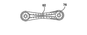
図3Bに示される一次インプラント部分16は、単独でまたは複数の隣接インプラントの一部分として使用でき、オステオトロピック/アンジオトロピック材料37などのものを組み込み、固定し、および/または安定化できる。図7A〜7Dに図示されるように、安定化は、メッシュ60またはプレート62などのインプラント間要素によって補助できる。メッシュ60またはプレート62などのインプラント間要素は、インプラントに機械的安定性を提供し得る。さらにインプラント間要素が、オステオトロピック/アンジオトロピック材料との機械的相互作用により、オステオトロピック/アンジオトロピック材料の安定性および保持性を提供するように、オステオトロピック/アンジオトロピック材料(図7に示していない)を、メッシュ60および/またはプレート62に結合できる。
The
図2Dに図示されるように、オステオトロピック/アンジオトロピック安定化材カバーねじ54は、このカバーねじのねじ山を一次挿入体16のねじ穴26に係合させることによって、インプラントに固定し、段階Iのアセンブリ14を形成することができる。
As shown in FIG. 2D, the osteotropic / angiotropic
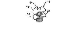
図2Gに示された本発明の一実施形態において、例えば、段階Iのアセンブリによって得られる骨成長よりもさらに骨成長が必要な場合、段階IIのアセンブリ64を利用できる。当然のことながら、さらに骨成長が必要なる場合は、1つ以上の追加段階のアセンブリが利用できる。図2Fおよび2Gに図示されるように、段階IIのアセンブリ64は、カバーねじ54に取って代わる。
In one embodiment of the invention shown in FIG. 2G, a stage II
図1Aに示されているように、段階IIのアセンブリ64は、係合部分66および本体部分70を含む。また、段階IIのアセンブリ64は、先に検討したように、例えば、血管細胞または骨芽細胞になって骨形成を誘導する前駆体細胞の分化や増殖に関連する薬物、蛋白質および遺伝物質などの内因性または外因性高分子の取り込み、放出および放出持続の能力を有する再吸収性または非再吸収性の多孔性表面材料であり得る骨結合部分33も含む。
As shown in FIG. 1A, stage II
図5Bに示されるように、本発明の他の実施形態において、段階IIのアセンブリ65は、骨結合部分に関して上記に検討した様式で、骨成長時に骨と移植片との最適な組込みと物理的安定性を可能にする形状、立体構造または他の特徴を有する骨結合部分31を有し得る。
As shown in FIG. 5B, in another embodiment of the present invention, the stage II
図1に示されるように、オステオトロピック/アンジオトロピック材料安定化材46は、幾つかの場合に外されて、図6Bに示されたものと同様なオステオトロピック/アンジオトロピック材料安定化材45に取替え得る。オステオトロピック/アンジオトロピック材料安定化材45は、幾つかの開口、各56を有する。先に検討したように、これらの開口56は、追加のオステオトロピック/アンジオトロピック材料の安定性を増大させ、血管の成長を可能にするか、および/または、開口を通って骨が形成し得る領域として役立つ。
As shown in FIG. 1, the osteotropic /
図2Fに示されるように、段階IIのアセンブリ64は、段階IIのアセンブリの冠側端74上にねじ穴72を有することができ、段階IIのカバーねじ76が、その中に螺合されている。また、段階IIアセンブリ64は、段階Iアセンブリ14への段階IIアセンブリ64の取り付けを可能にするスロット78などの器具係合面を有する。
As shown in FIG. 2F, the stage II
図5Aおよび5Bに示されるように、段階IIアセンブリ65の冠側端74は、研磨仕上げカラー80および角付き終末ライン82を有し得る。前記角付き終末ライン82は、角付き終末ライン25に関して検討したものと同様の性質を有する。
As shown in FIGS. 5A and 5B, the
図1B、2Gおよび4Cにおいて図示されたように段階IIのオステオトロピック/アンジオトロピック材料安定化材68が、段階IIのアセンブリ64にあってもよい。オステオトロピック/アンジオトロピック材料安定化材68は、一般に平面的な形状を有してもよく、細胞の接着を減らすか、および/または防ぐ材料から構成されてもよい。段階IIのオステオトロピック/アンジオトロピック材料安定化材68は、図1Aに図示された開口84を有する。段階IIのオステオトロピック/アンジオトロピック材料安定化材68は、ねじ穴72内に係合し得る段階IIのカバー76によって段階IIアセンブリ64の冠側端74に保持できる。あるいは、図6Cおよび6Dに示されているように、段階IIのオステオトロピック/アンジオトロピック材料安定化材68は、カバーねじと一体化できる。
A Stage II osteotropic /
図6Cに図示されるように、本発明の他の実施形態において、段階IIのオステオトロピック/アンジオトロピック材料安定化材69は、冠側端74の研磨仕上げのカラー82の上方および周囲にはめ合わせることができる。追加のオステオトロピック/アンジオトロピック材料39を段階IIのアセンブリ64に結合させて配置し、段階IIのオステオトロピック/アンジオトロピック材料安定化材68によって正しく保持してさらに骨成長を増強させる図4Cに示したのと同様な様式で、追加のオステオトロピック/アンジオトロピック材料(示していない)を、段階IIのアセンブリ65に結合させて配置し、段階IIのオステオトロピック/アンジオトロピック材料安定化材69によって正しく保持することができる。
As shown in FIG. 6C, in another embodiment of the present invention, the stage II osteotropic /
他の実施形態では、例えば、図3Cおよび4Cに示したように、複数の段階Iおよび/または段階IIのインプラントアセンブリを互いに隣接させ利用する。この実施形態において、インプラントを安定化、またはさらに支持するために、図7に示されたものと同様、追加の支え要素または固定要素を、1つのインプラントから隣のインプラントへと取り付けることができる。この支えにより、隣接したインプラントに対するさらなる位置安定性および/またはオステオトロピック/アンジオトロピック材料の固定が提供される。 In other embodiments, for example, as shown in FIGS. 3C and 4C, multiple Stage I and / or Stage II implant assemblies are utilized adjacent to each other. In this embodiment, additional support or fixation elements can be attached from one implant to the next, similar to that shown in FIG. 7, to stabilize or further support the implant. This support provides additional positional stability and / or fixation of the osteotropic / angiotropic material to the adjacent implant.
段階Iのアセンブリおよび段階IIのアセンブリに使用される材料は、インプラント材料としての公知の生体適合性を考えて選択され、骨結合、インプラントデザイン、および生体力学性の特性の周知の原則によって導かれる。実例としては、チタン、チタン合金、鋼鉄、合金鋼、コバルト合金、ニッケル合金、金属複合体、セラミック類、ガラス、生物由来材料、天然ポリマーおよび合成ポリマーなどの材料が、本発明の全体を通して単独で、または組合わせて使用できる。さらに、前記構造的インプラントおよび成分は、当業界で周知の再吸収性または非再吸収性材料のいずれから作製できる。前記成分が、主にチタンまたはチタン合金などの非再吸収性材料から作製される場合、前記構造的インプラントは、補綴再建のために適切に留まることになる。 The materials used for the Stage I and Stage II assemblies are selected for their known biocompatibility as implant materials and are guided by the well-known principles of bone bonding, implant design, and biomechanical properties. . Illustrative examples include materials such as titanium, titanium alloys, steels, alloy steels, cobalt alloys, nickel alloys, metal composites, ceramics, glass, biological materials, natural polymers and synthetic polymers alone throughout the present invention. Can be used in combination. Furthermore, the structural implants and components can be made from any of the resorbable or non-resorbable materials well known in the art. If the component is made primarily from a non-resorbable material such as titanium or a titanium alloy, the structural implant will remain in place for prosthetic reconstruction.
本発明は、自家性または非自家性のインプラント材料を使用して、または使用せずに、新たな骨組織の成長を促進する方法を包含する。図2A〜2Gおよび図3A〜3Cの例を参照し、一実施形態において、骨の一区分(図2A〜2Gには示していない)を、外科手術により露出させるか、またはその区分と接触できるようにし、器具係合面28と器具(示していない)とを係合させることにより予備安定化材36の高さまで、固定成分18を骨内に固定する。次いで、インプラントを例えば、約4mmから約6mmの深さまで骨内に固定すればよい。当然のことながら、この深さは、一次インプラント部分16に固定される場合、予備安定化材35の位置に基づくか、または別個の予備安定化材36が配置される位置に基づき得る。次に、予備安定化材36が別個の成分の場合、それを一次インプラント部分16の露出部分上に配置できる。配置の時、予備安定化材16は、インプラントの露出部分に対して螺合されていてもよいし、また、その上方を自由に通過してもよい。次いで、予備安定化材ナット40を締めることにより予備安定化材36を骨に対して固定できる。次いで、オステオトロピック/アンジオトロピック材料32をインプラント上に配置できる。また、オステオトロピック/アンジオトロピック材料32は、インプラントの経粘膜部分22により穿孔され得るか、別の方法でインプラントに結合し得る。次いで、オステオトロピック/アンジオトロピック材料安定化材46によってオステオトロピック/アンジオトロピック材料32が正しく固定される。
The present invention encompasses methods for promoting the growth of new bone tissue with or without the use of autologous or non-autologous implant materials. Referring to the examples of FIGS. 2A-2G and FIGS. 3A-3C, in one embodiment, a section of bone (not shown in FIGS. 2A-2G) can be surgically exposed or contacted with that section. Thus, the
より広い領域にわたって骨増加が望まれる場合、複数のインプラントを使用できる。図3は、段階Iの外科手術時におけるオステオトロピック/アンジオトロピック材料を有する複数のインプラントの使用を示している。もちろん、2つ以上のインプラントを組合わせて使用できる。複数のインプラントが使用される場合、インプラントは、互いに隣接した骨内に固定される。このことにより、任意の数の立体構造において、新たな骨の成長を得ることが可能になる。例えば、インプラントを実質的に線状のパターンで、または円形領域もしくは別の形状の領域上にわたって配置できる。 If bone augmentation is desired over a larger area, multiple implants can be used. FIG. 3 illustrates the use of multiple implants with osteotropic / angiotropic material during stage I surgery. Of course, two or more implants can be used in combination. When multiple implants are used, the implants are fixed in the bones adjacent to each other. This makes it possible to obtain new bone growth in any number of three-dimensional structures. For example, the implants can be arranged in a substantially linear pattern or over a circular or other shaped area.
図3Bに図示されるように、オステオトロピック/アンジオトロピック材料37を、複数の段階Iアセンブリ14と結合できる。例えば、オステオトロピック/アンジオトロピック材料37は、冠側端10上に取り付けできる拡張構造を形成する。次いで、図3Cに示されるように、オステオトロピック/アンジオトロピック材料安定化材46が、インプラントの冠側端10に固定された止め用ねじ54によって固定されると、オステオトロピック/アンジオトロピック材料37を正しく固定できる。図4Bに示されるような段階IIアセブリ64の場合、オステオトロピック/アンジオトロピック材料39を、2つ以上の段階IIアセンブリの冠側端74上に配置できる。次に図4Cに示されるように、オステオトロピック/アンジオトロピック材料39は、オステオトロピック/アンジオトロピック材料安定化材68によって正しく固定でき、また、インプラントの冠側端51内に固定された止め用ねじ76によって固定できる。上記で検討したように、複数のインプラントの間にオステオトロピック/アンジオトロピック材料37および/またはオステオトロピック/アンジオトロピック材料39を配置することによって、オステオトロピック/アンジオトロピック材料の保持性と安定性を増大させてもよい。例えば、オステオトロピック/アンジオトロピック材料を各端において、そこに挿入されたものによって物理的に支持および保持できる。
As illustrated in FIG. 3B, osteotropic /
図7A〜7Dに図示された本発明の他の実施形態において、メッシュ60およびプレート62のような支え材料または固定材料を複数のインプラントに結合できる。この追加の支えまたは固定は、骨内のインプラントをさらに安定化または支持するために、インプラントに接続できる。またこの支えは、オステオトロピック/アンジオトロピック材料(示していない)に対してさらなる位置安定性を提供するように機能し得る。次いで、オステオトロピック/アンジオトロピック材料内への上皮細胞および結合組織の線維芽細胞の内部成長に対するバリアとして働く、図3Bに関して先に検討した膜58と同様な膜によって、インプラント構造および結合したオステオトロピック/アンジオトロピック材料をコーティングすることができる。
In other embodiments of the present invention illustrated in FIGS. 7A-7D, support or fixation materials such as
次にインプラント部位を、外科手術業界において周知の方法を用いて、例えば、基本的なフラップ閉鎖によって閉じる。例えば、インプラント部位を閉じる上で不十分な組織しか存在しない場合は、先に記載した特別な外科手術法または追加の材料が使用できる。このような追加の材料は、自己、同種および/または人工の組織インプラント、天然物および/または構造物ならびにポリマーなど、医療界に周知の材料であり得る。 The implant site is then closed using methods well known in the surgical industry, for example, by basic flap closure. For example, if there is insufficient tissue to close the implant site, the special surgical techniques described above or additional materials can be used. Such additional materials can be materials well known to the medical community, such as self, homologous and / or artificial tissue implants, natural products and / or structures and polymers.
インプラント部位における骨成長の量および質は、ある期間後に判断される。この判断は、レントゲン写真または二重エネルギーX線吸収計(DEXA)走査によって遠隔的に、または直接的観察によって達成できる。 The amount and quality of bone growth at the implant site is determined after a period of time. This determination can be accomplished remotely by radiographs or dual energy X-ray absorption meter (DEXA) scanning or by direct observation.
図3Cを参照する。3ヵ月から6ヵ月後、前記部位を再度開いて、カバーねじ54およびオステオトロピック/アンジオトロピック材料安定化材46を取り外すことができる。次いで、骨を観察し、骨成長を判断する。骨成長が十分ならば、経粘膜補綴セグメント(示していない)を、前記インプラントに取り付けできる。補綴コネクターの取り付けには、例えば、医療界に周知の接着接続またはねじ保持アバットメントを利用できる。
Refer to FIG. 3C. After three to six months, the site can be reopened and the
追加の骨が必要な場合は、追加の段階、例えば、図1に示されたように、段階IIアセンブリ64を係合部分66によって、一次インプラント部分16の螺合された穿孔26などの接続部分へ固定する。この固定は、器具係合面を有する器具の係合(示していない)によって補助できる。図4A〜4Cは、移植された段階Iアセンブリ(各14)への段階IIアセンブリ(各64)の階層的装着ならびにオステオトロピック/アンジオトロピック材料37の組込みを図示している。段階IIアセンブリ64の配置および段階IIアセンブリ周囲の新たな石灰化組織の成熟後、段階Iアセンブリ14と段階IIアセンブリ64からなる組立てインプラントは、例えば、凡そ8mm以上の骨の高さによって支持および保持され、補綴セグメント(示していない)の取り付けの準備ができる。
If additional bone is required, an additional step, for example, a connecting portion such as a threaded
本発明の一実施形態の実験的使用として、骨同種インプラント足場の形態におけるオステオトロピック/アンジオトロピック材料の使用を含むものとした。チタン粗面の骨結合部分を有するインプラント、アルカリ面の骨結合部分を有するインプラント、およびリン酸カルシウム面の骨結合部分を有するインプラントとオステオトロピック/アンジオトロピック材料とを合わせて使用した。垂直方向の骨成長は、チタン粗面を有するインプラントでは、1.67mmから2.29mmの間の範囲で、アルカリ面を有するインプラントでは、1.79mmから2.15mmの間の範囲で、リン酸カルシウム面を有するインプラントでは、2.09mmから2.89mmの間の範囲で達成された。 Experimental use of an embodiment of the present invention included the use of osteotropic / angiotropic material in the form of a bone allograft scaffold. An implant having a bone-bonded portion with a rough titanium surface, an implant having a bone-bonded portion with an alkaline surface, and an implant having a bone-bonded portion with a calcium phosphate surface and an osteotropic / angiotropic material were used in combination. Vertical bone growth is in the range of 1.67 mm to 2.29 mm for implants with a rough titanium surface and in the range of 1.79 mm to 2.15 mm for implants with an alkaline surface. For implants having a diameter in the range between 2.09 mm and 2.89 mm.
前述の発明の好ましい実施形態を例示を目的として記載したが、当然のことながら本明細書において前述の説明を本発明の限定と考えるべきではない。したがって、本発明の精神と範囲から逸脱することなく、種々の変更、適合および代替が当業者に生じ得る。 While preferred embodiments of the foregoing invention have been described for purposes of illustration, it is to be understood that the foregoing description should not be construed as a limitation of the invention. Accordingly, various modifications, adaptations and alternatives can occur to those skilled in the art without departing from the spirit and scope of the invention.
10 冠側端
12 頂端
16 一次インプラント部分
18 固定部分
20 ねじ山
22 経粘膜部分
26 ねじ穴穿孔
28 スロット
30 骨結合部分
DESCRIPTION OF
Claims (13)
前記取付部位において前記インプラントに接続可能で、前記残存骨の高さから離隔され、前記残存骨の高さを超えた新たな歯槽骨成長を可能にする前記インプラントの露出部分周囲を規定する部分を有し、前記インプラントの露出部分周囲に通じる開口(56)を有する安定化材(45、46、68、69)と、
前記インプラントの露出部分周囲への新たな歯槽骨成長を可能にする、前記インプラントの露出部分周囲に配置された骨芽細胞系細胞および骨芽細胞のための表面および導管を提供する材料(32、37、39)と、
を含んでなり、
前記安定化材は前記材料に圧力をかけることが可能であることを特徴とする骨結合インプラントシステム。An implantable fixation portion (18) disposed within the residual bone and an exposed portion (29, 30, 31, 33) having an osteosynthesis surface and extending beyond the residual bone and beyond the height of the residual bone. And an attachment site to which the stabilizer (45, 46, 68, 69) is connected, and
A portion that is connectable to the implant at the attachment site, is spaced from the height of the residual bone, and defines a periphery of the exposed portion of the implant that allows new alveolar bone growth beyond the height of the residual bone A stabilizer (45, 46, 68, 69) having an opening (56) leading around the exposed portion of the implant ;
Said allowing new alveolar bone growth into the exposed portions surrounding the implant, the material providing a surface and the conduit for the osteoblast lineage cells and osteoblasts disposed on an exposed portion around the implant (32, 37, 39),
Ri name contains,
The bone graft implant system, wherein the stabilizing material can apply pressure to the material .
Applications Claiming Priority (3)
| Application Number | Priority Date | Filing Date | Title |
|---|---|---|---|
| US47870503P | 2003-06-13 | 2003-06-13 | |
| US60/478,705 | 2003-06-13 | ||
| PCT/US2004/018839 WO2005016388A2 (en) | 2003-06-13 | 2004-06-14 | Structural/biological implant system |
Publications (2)
| Publication Number | Publication Date |
|---|---|
| JP2007500585A JP2007500585A (en) | 2007-01-18 |
| JP5089169B2 true JP5089169B2 (en) | 2012-12-05 |
Family
ID=34193026
Family Applications (1)
| Application Number | Title | Priority Date | Filing Date |
|---|---|---|---|
| JP2006533779A Expired - Fee Related JP5089169B2 (en) | 2003-06-13 | 2004-06-14 | Structural / biological implant systems |
Country Status (8)
| Country | Link |
|---|---|
| US (3) | US20050033427A1 (en) |
| EP (1) | EP1631321A4 (en) |
| JP (1) | JP5089169B2 (en) |
| AU (1) | AU2004264835B2 (en) |
| BR (1) | BRPI0411442A (en) |
| CA (1) | CA2528022C (en) |
| WO (1) | WO2005016388A2 (en) |
| ZA (1) | ZA200600331B (en) |
Families Citing this family (26)
| Publication number | Priority date | Publication date | Assignee | Title |
|---|---|---|---|---|
| EP1631321A4 (en) | 2003-06-13 | 2008-10-29 | Univ Connecticut | Structural/biological implant system |
| US8641738B1 (en) | 2004-10-28 | 2014-02-04 | James W. Ogilvie | Method of treating scoliosis using a biological implant |
| US8123787B2 (en) * | 2004-10-28 | 2012-02-28 | Ogilvie James W | Method of treating scoliosis using a biological implant |
| CA2583911A1 (en) * | 2004-10-28 | 2006-05-11 | Microchips, Inc. | Orthopedic and dental implant devices providing controlled drug delivery |
| US20070016163A1 (en) * | 2005-06-28 | 2007-01-18 | Microchips, Inc. | Medical and dental implant devices for controlled drug delivery |
| US9539062B2 (en) | 2006-10-16 | 2017-01-10 | Natural Dental Implants, Ag | Methods of designing and manufacturing customized dental prosthesis for periodontal or osseointegration and related systems |
| US8454362B2 (en) | 2006-10-16 | 2013-06-04 | Natural Dental Implants Ag | Customized dental prosthesis for periodontal- or osseointegration, and related systems and methods |
| US7708557B2 (en) * | 2006-10-16 | 2010-05-04 | Natural Dental Implants Ag | Customized dental prosthesis for periodontal- or osseointegration, and related systems and methods |
| US8602780B2 (en) * | 2006-10-16 | 2013-12-10 | Natural Dental Implants, Ag | Customized dental prosthesis for periodontal or osseointegration and related systems and methods |
| US10426578B2 (en) | 2006-10-16 | 2019-10-01 | Natural Dental Implants, Ag | Customized dental prosthesis for periodontal or osseointegration and related systems |
| US9943410B2 (en) | 2011-02-28 | 2018-04-17 | DePuy Synthes Products, Inc. | Modular tissue scaffolds |
| ITMI20071617A1 (en) * | 2007-08-03 | 2009-02-04 | Gi Esse Technology S R L | DENTAL MEDICATED SYSTEM. |
| AU2009308866B2 (en) | 2008-10-30 | 2015-03-12 | Depuy Spine, Inc. | Systems and methods for delivering bone cement to a bone anchor |
| FI20095084A0 (en) | 2009-01-30 | 2009-01-30 | Pekka Vallittu | Composite and its use |
| JP5525189B2 (en) * | 2009-06-10 | 2014-06-18 | 株式会社プラトンジャパン | Bone guidance regeneration aid for implants |
| US8684732B2 (en) * | 2010-12-15 | 2014-04-01 | Bennett Jacoby | System and method for prevention and treatment of peri-implant infection |
| CA2748750A1 (en) * | 2011-08-11 | 2013-02-11 | John David FRENCH | Cap tack bone graft device |
| US9155580B2 (en) | 2011-08-25 | 2015-10-13 | Medos International Sarl | Multi-threaded cannulated bone anchors |
| KR101336780B1 (en) * | 2012-03-22 | 2013-12-04 | 서울대학교산학협력단 | Implant Mediated Drug Delivery device |
| US9539069B2 (en) | 2012-04-26 | 2017-01-10 | Zimmer Dental, Inc. | Dental implant wedges |
| US9554877B2 (en) * | 2012-07-31 | 2017-01-31 | Zimmer, Inc. | Dental regenerative device made of porous metal |
| CN103654978B (en) * | 2012-09-14 | 2016-06-29 | 陈碧芝 | Alveolar bone amplification device and longitudinal direction used thereof expand external member |
| US9782240B2 (en) * | 2013-11-01 | 2017-10-10 | Medintal Ltd. | Sub-periosteal extension for a dental implant |
| US11540900B2 (en) | 2018-05-03 | 2023-01-03 | The United States Of America As Represented By The Secretary Of The Navy | Dental ridge augmentation matrix with integrated dental implant surgical drill guide system |
| US10485632B1 (en) * | 2018-11-27 | 2019-11-26 | King Saud University | Intraoral attachment clip for attachment of objects to edentulous ridges |
| EP4046589A1 (en) * | 2021-02-23 | 2022-08-24 | Edwin Rostami | Dental implant assemblies, tools therefor and kit |
Family Cites Families (42)
| Publication number | Priority date | Publication date | Assignee | Title |
|---|---|---|---|---|
| JPS57156757A (en) * | 1981-03-23 | 1982-09-28 | Nisshin Kk | Dental implant |
| US4531915A (en) * | 1981-08-14 | 1985-07-30 | Tatum Jr O Hilt | Dental implant |
| US4531916A (en) * | 1983-07-08 | 1985-07-30 | W. L. Gore & Associates, Inc. | Dental implant with expanded PTFE gingival interface |
| US4682951A (en) * | 1986-05-28 | 1987-07-28 | Linkow Leonard I | Adjustable sinus lift implant |
| US4872840A (en) * | 1987-07-15 | 1989-10-10 | Team Incorporated | Dental implant and method |
| US4846683A (en) * | 1988-06-23 | 1989-07-11 | Implant Innovations, Inc. | Axially short dental implant fixture |
| SE8804641D0 (en) | 1988-12-23 | 1988-12-23 | Procordia Oratech Ab | SURGICAL BARRIER |
| JPH04231042A (en) * | 1990-09-20 | 1992-08-19 | Nikon Corp | Dental implant |
| JPH04224141A (en) | 1990-12-25 | 1992-08-13 | Sumitomo Electric Ind Ltd | Light illuminator |
| EP0504103B1 (en) * | 1991-03-11 | 1995-04-26 | Institut Straumann Ag | Means for attaching and holding a cover on a jaw bone |
| JP3244282B2 (en) * | 1991-05-17 | 2002-01-07 | オリンパス光学工業株式会社 | Dental implant |
| US5674725A (en) * | 1991-07-11 | 1997-10-07 | British Technology Group Limited | Implant materials having a phosphatase and an organophosphorus compound for in vivo mineralization of bone |
| DE4226465C2 (en) * | 1991-08-10 | 2003-12-04 | Gunze Kk | Jaw bone reproductive material |
| US5511565A (en) * | 1992-04-03 | 1996-04-30 | Syers; Charles S. | Guided bone and tissue generation device and method to be used during or after dental surgery or jaw surgery |
| US5372503A (en) * | 1993-04-27 | 1994-12-13 | Dental Marketing Specialists, Inc. | Method for installation of a dental implant |
| US5397235A (en) * | 1993-07-02 | 1995-03-14 | Dental Marketing Specialists, Inc. | Method for installation of dental implant |
| NL9201973A (en) | 1992-06-11 | 1994-01-03 | Lolke Johan Van Dijk | BIO-RESORABLE BARRIER ELEMENT. |
| SE9304093L (en) * | 1993-12-09 | 1995-05-02 | Nobelpharma Ab | Device for promoting bone growth |
| US5456601A (en) * | 1994-01-11 | 1995-10-10 | Sendax; Victor I. | Sinus dental implant stabilizer |
| DE9400537U1 (en) | 1994-01-14 | 1994-03-17 | Zl Microdent Attachment Gmbh | Tools for attaching and holding a cover on a jawbone |
| US5538424A (en) * | 1994-05-18 | 1996-07-23 | Gelb; David A. | Radiographic depth and prosthetic positioning guide |
| US5632745A (en) * | 1995-02-07 | 1997-05-27 | R&D Biologicals, Inc. | Surgical implantation of cartilage repair unit |
| WO1997021393A1 (en) * | 1995-12-08 | 1997-06-19 | Calcitek, Inc. | Dental implant having multiple tectured surfaces |
| US5839899A (en) * | 1996-03-01 | 1998-11-24 | Robinson; Dane Q. | Method and apparatus for growing jaw bone utilizing a guided-tissue regeneration plate support and fixation system |
| AT403002B (en) * | 1996-05-29 | 1997-10-27 | Mke Metall Kunststoffwaren | FILM OR MEMBRANE FOR COVERING BONE DEFECTS, METHOD FOR PRODUCING THE FILM AND NAIL FOR FIXING THE POSITION OF SUCH A FILM |
| FR2753366A1 (en) * | 1996-09-13 | 1998-03-20 | Marzouk Jean | Mucosa-bone implant pin |
| US5833463A (en) * | 1996-12-09 | 1998-11-10 | Hurson; Steven M. | Titanium surface treated dental screw for attaching a prosthetic component to an implant |
| CA2279526A1 (en) * | 1997-02-25 | 1998-08-27 | Nobel Biocare Ab | Bone anchoring element |
| US5961329A (en) * | 1997-07-02 | 1999-10-05 | Stucki-Mccormick; Suzanne U. | Combination distraction dental implant and method of use |
| SE9802571D0 (en) * | 1998-07-17 | 1998-07-17 | Astra Ab | Implant |
| WO2000035510A1 (en) * | 1998-12-14 | 2000-06-22 | Osteotech, Inc. | Bone graft and guided bone regeneration method |
| AT407107B (en) * | 1999-05-10 | 2000-12-27 | Mke Metall Kunststoffwaren | DENTAL IMPLANT |
| CN1351482A (en) * | 2000-02-21 | 2002-05-29 | 张相健 | Method and its materials for aveolar ridge protection |
| EP1184003B1 (en) * | 2000-09-04 | 2003-07-02 | Maillefer Instruments Holding SA | A dental root canal-treating instrument |
| AU2001288021A1 (en) | 2000-09-05 | 2002-03-22 | Technion Research And Development Foundation Ltd. | Hydrogel incorporated with bone growth promoting agents for dental and oral surgery |
| JP4698033B2 (en) * | 2001-01-31 | 2011-06-08 | 京セラ株式会社 | Bone repair device |
| DE10138374A1 (en) * | 2001-08-11 | 2003-03-06 | Robert Eisenburger | Dental implant and cap |
| US6758673B2 (en) | 2001-12-05 | 2004-07-06 | Ofir Fromovich | Periosteal distraction |
| US20030118968A1 (en) * | 2001-12-20 | 2003-06-26 | Massoud Yehia Aly | Dental implant and method to regain interproximal bone and reconstruct the interdental papilla |
| US20030232308A1 (en) * | 2002-06-14 | 2003-12-18 | Simmons Earl Wayne | Method and apparatus for dental implants |
| EP1631321A4 (en) | 2003-06-13 | 2008-10-29 | Univ Connecticut | Structural/biological implant system |
| US20060008773A1 (en) * | 2004-07-08 | 2006-01-12 | Jung-Yen Liao | Titanium-mesh umbrella device for bone grafting |
-
2004
- 2004-06-14 EP EP04776533A patent/EP1631321A4/en not_active Withdrawn
- 2004-06-14 AU AU2004264835A patent/AU2004264835B2/en not_active Ceased
- 2004-06-14 ZA ZA200600331A patent/ZA200600331B/en unknown
- 2004-06-14 JP JP2006533779A patent/JP5089169B2/en not_active Expired - Fee Related
- 2004-06-14 BR BRPI0411442-6A patent/BRPI0411442A/en not_active Application Discontinuation
- 2004-06-14 CA CA2528022A patent/CA2528022C/en not_active Expired - Fee Related
- 2004-06-14 US US10/867,487 patent/US20050033427A1/en not_active Abandoned
- 2004-06-14 WO PCT/US2004/018839 patent/WO2005016388A2/en active Application Filing
-
2008
- 2008-10-28 US US12/259,608 patent/US8152848B2/en not_active Expired - Fee Related
-
2012
- 2012-01-31 US US13/362,105 patent/US8986381B2/en not_active Expired - Fee Related
Also Published As
| Publication number | Publication date |
|---|---|
| EP1631321A2 (en) | 2006-03-08 |
| US8152848B2 (en) | 2012-04-10 |
| US8986381B2 (en) | 2015-03-24 |
| ZA200600331B (en) | 2007-05-30 |
| AU2004264835A1 (en) | 2005-02-24 |
| AU2004264835B2 (en) | 2009-10-29 |
| BRPI0411442A (en) | 2006-07-18 |
| CA2528022C (en) | 2012-08-21 |
| US20090117519A1 (en) | 2009-05-07 |
| CA2528022A1 (en) | 2005-02-24 |
| WO2005016388A2 (en) | 2005-02-24 |
| US20050033427A1 (en) | 2005-02-10 |
| WO2005016388A3 (en) | 2006-03-30 |
| EP1631321A4 (en) | 2008-10-29 |
| US20120197397A1 (en) | 2012-08-02 |
| JP2007500585A (en) | 2007-01-18 |
Similar Documents
| Publication | Publication Date | Title |
|---|---|---|
| JP5089169B2 (en) | Structural / biological implant systems | |
| von Wilmowsky et al. | Implants in bone: Part I. A current overview about tissue response, surface modifications and future perspectives | |
| AU2003250711B2 (en) | Implant for implanting in bone tissue or in bone tissue supplemented with bone substitute material | |
| KR101121146B1 (en) | Method for fixing an implant, fixing member for the implant and implant composite | |
| AU718801B2 (en) | Resorbable, macro-porous, non-collapsing and flexible membrane barrier for skeletal repair and regeneration | |
| AU761058B2 (en) | Membrane with tissue-guiding surface corrugations | |
| US6126662A (en) | Bone implant | |
| EP1119311B1 (en) | Bone implant | |
| Dimitriou et al. | Biomaterial osseointegration enhancement with biophysical stimulation | |
| JP6352183B2 (en) | Body made of bone substitute material and manufacturing method | |
| US20080020349A1 (en) | Bone implant | |
| EP0776639A3 (en) | Bone fusion dental implant with hybrid anchor | |
| US20150265407A1 (en) | Multi-Layer Distraction Membrane for Bone Defects | |
| WO2004010887A1 (en) | Arrangement for using osteoinductive or bioactive material to induce bone and/or increase the stability of implants in the jaw bone, and an implant intended for this purpose. | |
| JP2019500085A (en) | Bioabsorbable fixing nail | |
| Wen et al. | Bone tissue engineering around dental implants | |
| RU2738008C1 (en) | Implant unit | |
| RU2262912C2 (en) | Hip joint endoprosthesis pedicle | |
| EA035482B1 (en) | Endoosseous all-ceramic screw single-stage immediate implant | |
| Swaid | BIOLOGY OF OSSEOINTEGRATION OF DENTAL IMPLANTS | |
| BRPI1100901A2 (en) | bioimplant |
Legal Events
| Date | Code | Title | Description |
|---|---|---|---|
| A621 | Written request for application examination |
Free format text: JAPANESE INTERMEDIATE CODE: A621 Effective date: 20070604 |
|
| A131 | Notification of reasons for refusal |
Free format text: JAPANESE INTERMEDIATE CODE: A131 Effective date: 20090526 |
|
| A521 | Written amendment |
Free format text: JAPANESE INTERMEDIATE CODE: A523 Effective date: 20090819 |
|
| A131 | Notification of reasons for refusal |
Free format text: JAPANESE INTERMEDIATE CODE: A131 Effective date: 20091020 |
|
| A601 | Written request for extension of time |
Free format text: JAPANESE INTERMEDIATE CODE: A601 Effective date: 20100118 |
|
| A602 | Written permission of extension of time |
Free format text: JAPANESE INTERMEDIATE CODE: A602 Effective date: 20100125 |
|
| A521 | Written amendment |
Free format text: JAPANESE INTERMEDIATE CODE: A523 Effective date: 20100415 |
|
| A072 | Dismissal of procedure [no reply to invitation to correct request for examination] |
Free format text: JAPANESE INTERMEDIATE CODE: A072 Effective date: 20100810 |
|
| A02 | Decision of refusal |
Free format text: JAPANESE INTERMEDIATE CODE: A02 Effective date: 20100921 |
|
| A521 | Written amendment |
Free format text: JAPANESE INTERMEDIATE CODE: A523 Effective date: 20101216 |
|
| A911 | Transfer of reconsideration by examiner before appeal (zenchi) |
Free format text: JAPANESE INTERMEDIATE CODE: A911 Effective date: 20110215 |
|
| A912 | Removal of reconsideration by examiner before appeal (zenchi) |
Free format text: JAPANESE INTERMEDIATE CODE: A912 Effective date: 20110408 |
|
| RD03 | Notification of appointment of power of attorney |
Free format text: JAPANESE INTERMEDIATE CODE: A7423 Effective date: 20120622 |
|
| RD04 | Notification of resignation of power of attorney |
Free format text: JAPANESE INTERMEDIATE CODE: A7424 Effective date: 20120625 |
|
| A521 | Written amendment |
Free format text: JAPANESE INTERMEDIATE CODE: A821 Effective date: 20120622 |
|
| A521 | Written amendment |
Free format text: JAPANESE INTERMEDIATE CODE: A523 Effective date: 20120720 |
|
| A01 | Written decision to grant a patent or to grant a registration (utility model) |
Free format text: JAPANESE INTERMEDIATE CODE: A01 |
|
| A61 | First payment of annual fees (during grant procedure) |
Free format text: JAPANESE INTERMEDIATE CODE: A61 Effective date: 20120911 |
|
| FPAY | Renewal fee payment (event date is renewal date of database) |
Free format text: PAYMENT UNTIL: 20150921 Year of fee payment: 3 |
|
| R150 | Certificate of patent or registration of utility model |
Free format text: JAPANESE INTERMEDIATE CODE: R150 |
|
| LAPS | Cancellation because of no payment of annual fees |