JP5087953B2 - Tractor - Google Patents
Tractor Download PDFInfo
- Publication number
- JP5087953B2 JP5087953B2 JP2007049287A JP2007049287A JP5087953B2 JP 5087953 B2 JP5087953 B2 JP 5087953B2 JP 2007049287 A JP2007049287 A JP 2007049287A JP 2007049287 A JP2007049287 A JP 2007049287A JP 5087953 B2 JP5087953 B2 JP 5087953B2
- Authority
- JP
- Japan
- Prior art keywords
- speed
- lever
- gear
- transmission
- rear cover
- Prior art date
- Legal status (The legal status is an assumption and is not a legal conclusion. Google has not performed a legal analysis and makes no representation as to the accuracy of the status listed.)
- Expired - Fee Related
Links
Images


Description
この発明は、農業機械であるトラクタに関する。特に、油圧式無段変速装置による車速制御手段を備えたものである。 The present invention relates to a tractor that is an agricultural machine. In particular, the vehicle is provided with vehicle speed control means using a hydraulic continuously variable transmission.
特許文献1には、エンジン負荷を検出するエンジン回転数検出器を設け、ロータリ作業機による作業負荷によってエンジン回転数が減少すると、走行速度を制御する油圧式無段変速装置を減速制御し、エンジン回転数が増加すると、油圧式無段変速装置を増速制御し、所定の耕耘速度で作業する耕耘速度制御手段が開示されている。
従来のエンジン負荷制御では、耕耘作業中、ロータリ作業機に負荷がかかると、エンジン回転が低下する。このエンジン回転数の変化を読み取ってロータリ作業機の耕耘速度を制御するものであるが、この場合、エンジン回転がダウンしてから耕耘速度を落とすものであるため反応が遅く、作業の能率低下はもとより、エンストなどを惹き起す問題があった。 In conventional engine load control, when a load is applied to the rotary working machine during tillage work, the engine rotation is reduced. The change in the engine speed is read to control the tilling speed of the rotary work machine. In this case, the reaction speed is slow because the tilling speed is reduced after the engine speed is down, and the work efficiency is reduced. Of course, there was a problem that caused engine stalls.
本発明の課題は、ロータリのリヤカバーの動きを常にセンシングして、リヤカバーが設定値を一定以上越えると、車速を制御する油圧式無段変速装置のトラニオン軸を減速方向に作動させ、リヤカバーが元の位置に復帰すると車速を元に戻すように制御することで、エンジン回転を落すことなく、制御反応を速くして上記問題点を解消せんとするものである。 The object of the present invention is to constantly sense the movement of the rotary rear cover, and when the rear cover exceeds a set value, the trunnion shaft of the hydraulic continuously variable transmission that controls the vehicle speed is operated in the deceleration direction. By returning the vehicle speed to the original position, the vehicle speed is controlled to return to the original value, thereby speeding up the control reaction without reducing the engine speed, thereby eliminating the above problem.
この発明は、上記課題を解決すべく次のような技術的手段を講じた。
すなわち、請求項1記載の発明は、車体の後部に昇降可能なロータリ作業機(R)を装着して設け、該ロータリ作業機(R)に装着されたリヤカバー(18)の上下回動角を検出するリヤカバーセンサ(22)を設け、前記リヤカバー(18)の回動角が一定範囲以上を越えると、前記リヤカバーセンサ(22)の検出結果に基づき、車速を制御する油圧式無段変速装置(34)のトラニオン軸(92)を減速方向に制御し、回動角が一定範囲以上を越えたリヤカバー(18)が所定の耕深制御範囲に戻るとトラニオン軸(92)を所定速度範囲内に復帰する制御を行うことを特徴とするトラクタとしたものである。
In order to solve the above problems, the present invention has taken the following technical means.
That is, the invention according to claim 1 is provided with a rotary work machine (R) that can be raised and lowered at the rear part of the vehicle body, and the vertical rotation angle of the rear cover (18) attached to the rotary work machine (R). A hydraulic continuously variable transmission (22) for controlling the vehicle speed based on the detection result of the rear cover sensor (22) when a rear cover sensor (22) for detection is provided and the rotation angle of the rear cover (18) exceeds a predetermined range or more. 34) When the trunnion shaft (92) is controlled in the deceleration direction and the rear cover (18) whose rotation angle exceeds a certain range returns to the predetermined tilling depth control range, the trunnion shaft (92) is brought into the predetermined speed range. The tractor is characterized by performing return control .
耕耘作業時において、リヤカバー(18)の回動角が一定範囲以上を越えると、リヤカバーセンサ(22)の検出結果に基づき、油圧式無段変速装置(34)のトラニオン軸(92)を減速方向に制御し、車速を所定の速度に減速する。リヤカバー(18)が元の位置に復帰すると、車速も元の速度に復帰し、所定の耕耘速度を維持しながら耕耘作業が能率よく行える。 During tillage work, if the rotation angle of the rear cover (18) exceeds a certain range , the trunnion shaft (92) of the hydraulic continuously variable transmission (34) is decelerated based on the detection result of the rear cover sensor (22). To reduce the vehicle speed to a predetermined speed. When the rear cover (18) returns to the original position, the vehicle speed also returns to the original speed, and the tilling work can be performed efficiently while maintaining a predetermined tilling speed.
請求項1の発明によれば、リヤカバーの回動角が一定範囲以上を越えると、トラニオン軸を減速制御するので、実際にエンジンに負荷が作用してエンジン回転数が低下を始めてから車速を減速制御するものに比べて、反応よく車速を減速制御できるようになる。そして、エンジン回転が落ちることもなく、適正な耕耘速度を維持しながら、耕耘作業を能率よく行うことができる。 According to the first aspect of the present invention, when the rotation angle of the rear cover exceeds a certain range, the trunnion shaft is controlled to decelerate. Therefore, the vehicle speed is decelerated after the load is actually applied to the engine and the engine speed starts to decrease. Compared to what is controlled, the vehicle speed can be controlled more responsively. And, the rotation of the engine can be efficiently performed while maintaining an appropriate tillage speed without causing the engine rotation to drop.
この発明の実施例を図面に基づき説明する。
なお、本明細書において作業車両の前進方向に向かって左右方向をそれぞれ左、右といい、前進方向を前、後進方向を後という。
An embodiment of the invention will be described with reference to the drawings.
In the present specification, the left and right directions in the forward direction of the work vehicle are referred to as left and right, respectively, the forward direction is referred to as front, and the reverse direction is referred to as rear.
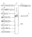
図1にトラクタの全体側面図、図2に図1のトラクタの平面図、図3は図1のトラクタの変速装置の動力伝達経路図、図4は該変速装置の制御ブロック図を示す。
図1〜図3に示すトラクタは機体の前後部に左右の前輪2、2と左右の後輪3、3を備え、機体の前部に搭載したエンジンEの回転動力をミッションケース4内の変速装置によって適宜減速して、これらの左右の前輪2、2と左右の後輪3、3に伝えるように構成している。ミッションケ−ス4の後上部には油圧シリンダケース5が搭載され、このシリンダケース5の左右両側部には、油圧昇降機構の一部を構成するリフトアーム12,12が回動自在に枢支されている。シリンダケース5内に収容されているリフトシリンダ8に作動油を供給するとリフトアーム12が上方に回動し、排出するとリフトアーム12は下降するようになっている。
1 is an overall side view of the tractor, FIG. 2 is a plan view of the tractor of FIG. 1, FIG. 3 is a power transmission path diagram of the transmission of the tractor of FIG. 1, and FIG. 4 is a control block diagram of the transmission.
The tractor shown in FIGS. 1 to 3 includes left and right
機体の中央のハンドルポスト6にはステアリングハンドル7が支持され、その後方には座席9が設けられている。ステアリングハンドル7の下方には機体の進行方向を前後方向に切り換える前後進レバー10が設けられている。この前後進レバー10を前側に移動させると機体は前進し、後方へ移動させると後進する。また、ハンドルポスト6を挟んで前後進レバー10の反対側にはアクセルレバー11が設けられ、また、ステップフロア13の右コーナー部にはアクセルペダル15と左右のブレーキペダル16,17が配置され、ステップフロア13の左コーナ部にはクラッチペダル19が配置されている。
A steering handle 7 is supported on the
また、1速から8速まで変速段を選択可能な主変速レバー(HSTレバー)20は操縦席9の左前方部にあり、低速、中速、高速及び中立のいずれかの位置を選択できる副変速レバー21はその後方にあり、さらにその後方に1〜3速と中立位置を選択できるPTO変速レバー23が設けられている。さらに操縦席9の右側にはロータリ作業機Rの高さを設定するポジションレバー24と圃場の耕耘深さを自動的に設定する自動耕深レバー25、これらのレバー24,25の後ろにロータリ作業機Rの右上げスイッチ27と右下げスイッチ28が配置され、更にその後ろに自動水平面に対して水平スイッチ29(オンでトラクタの絶対水平位置(圃場面に対する水平でなく、地球の水平面に対して水平を保つ)とバックアップスイッチ30(オンで前後進レバー10が後進位置にあるとき作業機上げ用リンク31が作業機を上昇させる)が配置されている。また、機体の後方にはロータリ作業機Rを連結する前記リンク31が設けられている。リフトアーム12の回動側基部には、ロータリ作業機Rの昇降位置を検出する手段としてリフトアームセンサ14が設けられ、このリフトアームセンサ14にてリフトアーム12の回動角を検出し、コントローラ90によりロータリ作業機Rの昇降高さを演算するようになっている。また、ロータリ作業機Rのメインカバーの後端部にリヤカバー18を上下回動自在に取り付け、一定範囲内ではリヤカバーセンサ22によりリヤカバー18の回動角を検出して、コントローラ90にてロータリ作業機Rの耕深量を演算する構成としている。
A main transmission lever (HST lever) 20 capable of selecting a gear position from 1st to 8th is located in the left front portion of the
そして、リヤカバー18の回動角が一定範囲以上を越える(耕耘作業負荷大となる)と、リヤカバーセンサ22の検出結果に基づき、HST34のトラニオン軸92を減速方向に制御するトラニオン減速制御手段(A)がコントローラ90に制御プログラム形式で備えられている。つまり、リヤカバーセンサ22が一定以上の耕耘負荷を検出すると、トラニオン軸92を減速方向に作動させるトラニオン油圧シリンダ93へコントローラ90から制御信号を出力するようになっている。リヤカバーが所定の耕深制御範囲内に戻ると、トラニオン軸も所定速度範囲内に復帰し、所定の耕耘速度を維持しながら耕深制御が行えるようになっている。
Then, when the rotation angle of the
図3は、本実施例の静油圧式無段変速装置(HST)34を有するトラクタの走行伝動系を表した経路図である。エンジンEの回転動力はペダル操作式のクラッチペダル19の踏み込みで作動するメインクラッチ32に伝えられた後、HST入力軸33からHST34に伝達される。HST34は容量可変式の油圧ポンプ34aと定容量式の油圧モータ34bを備えた油圧閉回路34cを備えており、HST入力軸33から導入された動力により油圧ポンプ34aを作動させて、油圧ポンプ34aに設けられた斜板34dの傾斜角度に応じた圧油を油圧閉回路34cから油圧モータ34bに供給し、該油圧モータ34bにより走行出力軸36を駆動させて噛合式の変速装置38へ動力を伝達させる。
FIG. 3 is a route diagram showing a traveling transmission system of a tractor having the hydrostatic continuously variable transmission (HST) 34 of the present embodiment. The rotational power of the engine E is transmitted to the
噛合式の変速装置38の副変速クラッチ39は図3の左右にスライド可能であり、図示する位置にあるときは走行出力軸36からの動力がギア41を介して高速段ギア42から副変速クラッチ39へ、該副変速クラッチ39から変速軸43のギア45に伝達され、変速軸43の回転がデフ装置46を介して後輪3が副変速高速段の走行速度で駆動される。
The
また、副変速クラッチ39は図3に示す位置から右側に移動して、副変速クラッチ39が変速軸43のギア45と中速段ギア47に係止すると、走行出力軸36からの動力がギア41を介してギア49からギア50、ギア51及びギア47を順次経由して副変速クラッチ39へ伝達され、さらに該副変速クラッチ39から変速軸43のギア45に伝達され変速軸43の回転がデフ装置46を介して後輪3が副変速中速段の走行速度で駆動する。
Further, when the
副変速クラッチ39がさらに右側に移動して変速軸43のギア45と低速ギア55に係止すると、走行出力軸36からの動力がギア41を介してギア49からギア56へ、さらにギア56からギア57へ伝達され、ギア57と同軸のギア55から副変速クラッチ39へ、さらに該副変速クラッチ39から変速軸43のギア45に伝達され、変速軸43の回動がデフ装置46を介して後輪3が副変速低速段の走行速度で駆動される。
When the
また、副変速クラッチ39のスライド位置が左右いずれの側にあっても、変速軸43からの出力がギア53、59、60等を順次経由して前輪出力軸61に伝達される。このとき油圧クラッチ63が接続していると、デフ装置65を介して前輪2が後輪3と共に駆動する四輪駆動となり、また油圧クラッチ64が接続していると、前輪増速の四輪駆動となる。油圧クラッチ63と油圧クラッチ64が共に接続することはなく、また油圧クラッチ63と油圧クラッチ64が共に接続していないと後輪3のみが駆動する二輪駆動となる。
Even if the sliding position of the
一方、HST入力軸33から容量可変式の油圧ポンプ34aに入力された動力はポンプ出力軸66からPTO用の駆動系に伝達される。PTO用の駆動系にはPTO正逆クラッチ67とPTO副変速クラッチ68があり、トラクタが路上走行時は前記クラッチ67,68のいずれか一方または両方が非接続状態であり、作業機を駆動させるPTO駆動系は駆動されない。
On the other hand, the power input from the
圃場内での作業機を用いる作業時は、アクセルレバー11を操縦者側(手前)に引いてエンジン回転数を定格回転数、または定格回転数以上から最大回転数の一定回転にしているのでHST入力軸33とポンプ出力軸66が同じ回転数で一定回転する。図3に示す状態は中立状態であり、ポンプ出力軸66と直結しているPTO軸69が共に回転する。PTO正逆クラッチ67を図示左方向にスライドさせるとPTO正逆クラッチ67がPTO軸69のギア70とギア71に噛合するので、PTO軸69の動力はギヤ70,PTO正逆クラッチ67,ギヤ71,71a、72、74、78、β、76を介して、PTO伝達軸75を駆動させる(PTO逆転)。又、PTO正逆クラッチ67を右にスライドさせるとPTO軸69の動力は、ギヤ70、PTO正逆クラッチ67、ギヤα、β、76を介して、PTO伝達軸75を駆動(PTO正転)する。
When working with the work implement in the field, the HST is set because the engine speed is set to the rated speed or a constant speed from the rated speed to the maximum speed by pulling the accelerator lever 11 toward the operator (front side). The
ギア72と一体のギア74の駆動に連動するギア78からの動力もPTO伝達軸75に伝達され、PTO副変速クラッチ68が図示位置より左方向に移動した位置にあると、ギア79とギア80を介してギアドック81がPTO副変速クラッチ68に設けられたギアドック83と噛合してPTO駆動軸84によりPTO1速が得られる。またPTO副変速クラッチ68が図示位置から左または右方向に移動すると、それぞれの場合に噛合するPTO副変速低速段ギア85またはPTO副変速高速段ギア86に動力が伝達され、PTO副変速低速段ギヤ85→ギヤ68a→PTO駆動軸84でPTO2速、PTO副変速高速段ギヤ86→ギヤ68b→PTO駆動軸84でPTO3速が得られる。
The power from the
上記構成のトラクタは路上走行時にはクラッチペダル19を踏み込み、副変速レバー21を路上走行に適した位置(基本は高速位置であり、中速位置または低速位置にする場合もある)に設定する。次いでHSTレバー20を任意の位置に移動する。HSTレバー20は最低速1速から最高速8速まで選択可能であるが、路上走行時の基本は8速である。
The tractor having the above-described configuration depresses the
次いで前後進レバー10を前進側または後進側に移動し、クラッチペダル19をゆっくり離しながら(メインクラッチ32を接続して)アクセルペダル15を踏んでエンジン回転数を上げていく。このときアクセルペダル15を最大限に踏み込んでも、最大速度はHSTレバー20の最大速度段(8速)の位置に規制される。
Next, the forward /
また、圃場内での作業時はクラッチペダル19を踏み込んだ後、副変速レバー21を適宜の位置(基本は低速または中速位置)に設定する。次いでHSTレバー20を任意の位置(作業の種類に応じて1速から8速まで選択可能)に移動し、前後進レバー10を前進位置に移動させる。アクセルレバー11を操縦者側(手前)に移動してエンジン回転数を定格回転数または定格回転数以上の最大回転数までの間に設定する。次いでクラッチペダル19を離しながら(メインクラッチ32を接続して)前進させる。このときエンジン回転数は定格回転数または定格回転数以上の最大回転数までの間に設定されるが、作業速度はHSTレバー20の位置で規制される。
Further, when working in the field, after depressing the
図5にはハンドルポスト6と操縦席付近の機体とHSTレバー20のみの左側面図を示す。HSTレバー20は1〜8速まで変速段を変更可能であり、各速度段に対応するポジション位置を検出できるポジションセンサ22aが該レバー20の基部に設けられている。前記ポジションセンサ20aの検出値はコントローラ90(図4)に出力される。
FIG. 5 shows a left side view of only the
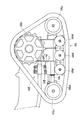
また、図6には変速装置ケース91の平面図(図6(a))と該変速装置ケース91内に収納されているHST34の平面図(図6(b))を示す。また図7には図6の矢印A方向から見た変速装置ケース91の側面図を示す。
6 shows a plan view of the transmission case 91 (FIG. 6A) and a plan view of the
図5〜図7に示すようにHST34のトラニオン軸92を回動させる油圧シリンダ93と変速装置ケース91の外部に突出した部分のトラニオン軸92を連結するリンク機構95を変速装置ケース91の外壁部分に取り付けている。シリンダ93のピストンロッド93aの先端部に回動自在に一端を接続したアーム95aの他端を変速装置ケース91の外壁に回動自在に支持させ、さらに該アーム95aのもう一方の端部には該アーム95aに直交する方向に設けたロッド95bの一端が回動自在に設けられ、さらにこのロッド95bの他端には回動自在な短いアーム95cを介してアーム95aと略平行な方向に長さ調節可能なロッド95dの端部を回動自在に連結する。
As shown in FIGS. 5 to 7, a
該長さ調節可能なロッド95dの他端は回動自在に短いアーム95eの一端に連結し、該短いアーム95eの他端にはボス95fが固定している。ボス95fは、ボルトpで軸qに固定されている。軸qは変速装置ケース91に対して回転自在に支持されている。軸qには、プレート95gが固着している。該プレート95gの他端はトラニオン軸92と一体のトラニオンアーム95jの端部にリンクアーム95hが回動自在にピンrで連結している。リンクアーム95hの前記プレート95gの連結部の反対側の端部はトラニオン軸92と一体のトラニオンアーム95jの端部に連結している。またプレート95gとリンクアーム95hの連結部ピンrは軸qを回動支点として変速装置ケース91に固定された扇状部材95kの円弧状の長穴95k1内を摺動自在になっており、またピンrが長穴95k1内だけを摺動可能なためにトラニオンアーム95jの回動範囲もピンrの摺動に連動する範囲内に規制される。
The other end of the
上記リンク機構95により油圧シリンダ93の作動が前記アーム95aやロッド95dなどに連動してトラニオンアーム95jがトラニオン軸92と共に回動することになる。また、トラニオンアーム95jの側面が変速装置ケース91に支持されたローラ95mの側面に当接しながらシリンダ93によりトラニオンアーム95jが回動する。
By the
図6に示す状態はトラニオン軸92がHST34の油圧ポンプ34aの斜板34dを車両前進側に向けた状態を示しており、図8の変速装置ケース91の平面図(図8(a))と該変速装置ケース91内に収納されているHST34の平面図(図8(b))を示す状態はHST34の油圧ポンプ34aの斜板34dを中立位置にした状態を示しており、トラニオンアーム95jのカム凹部95nに対してローラ95m(ローラ95mはx方向にバネでおされている。)が嵌まり込む位置がトラニオン軸92の中立位置である。ローラ95mは、ブラケット94に対しスライド自在なスライドピン95qに取り付けられ、付勢スプリング95sによってトラニオンアーム95mのカム凹部側に向けて(x方向)押圧付勢されている(図9参照)。
6 shows a state in which the
また、図10の変速装置ケース91の平面図(図10(a))と該変速装置ケース91内に収納されているHST34の平面図(図10(b))を示す状態は、HST34の油圧ポンプ34aの斜板34dを後進側に向けた状態を示している。
10 is a plan view of the transmission case 91 (FIG. 10A) and a plan view of the
図11は前後進レバー10の基部に設けたシフトスイッチ10a、10bの配置とその作動態様を示す図である。図11(a)と図11(c)には前後進レバー10が前進位置と後進位置にある場合の前後進レバー10の基部に設けた前進シフトスイッチ10aと後進シフトスイッチ10bが作動する配置図をそれぞれ示し、図11(b)には前後進レバー10が中立位置にある場合に前進シフトスイッチ10aと後進シフトスイッチ10bのいずれにも当接しない場合の配置図を示す。
FIG. 11 is a diagram showing the arrangement of
上記前後進レバー10の前進シフトスイッチ10aが作動するようにHSTレバー11を中立位置から前進側に倒すと前進方向に動かす準備ができ、前後進レバー10の後進シフトスイッチ10bが作動するようにHSTレバー11を中立位置から後進側に倒すと後進方向に動かす準備ができる。
When the HST lever 11 is tilted from the neutral position to the forward side so that the
図12は、前後進レバーのリバーサカム100の従来例を示すもので、クラッチペダルを踏み込み操作すると、ロックピン101が上昇して前後進レバーのロックプレートをロックするものであるが、従来のリバーサカムでは1枚物で構成されているため、ロックピンの調整に時間がかかり、特に、後進側の独立調整が困難であった。本例では、図13に示すように、リバーサルカム100を100F,100N,及び、100Rに3分割してカムの動きを規制するようにしたものである。規制カム100F,100N,100Rのそれぞれをボルト102での角度調整が容易となり、ピンの位置を固定できるので部品数も少なくて済み、前進、中立、後進全ての位置でカムが固定できる。
FIG. 12 shows a conventional example of the reverse
上記HST減速制御手段は、旋回制御にも応用することができる。例えば、HST34のトラニオン軸92をアクチュエータ(例えばトラニオン油圧シリンダ93)でコントローラ90を介して変速制御するようにし、モード切替スイッチが耕耘モードである時、耕耘作業時の変速位置(例えば、8速、7速、6速)で旋回に入ると、自動的に車速を1段落とすように(例えば旋回前が6速であれば5速に落とす。)減速制御する。
The HST deceleration control means can also be applied to turning control. For example, the
これによると、機体が旋回時においてエンジン回転を落とすものではないため、余裕をもって旋回できて安全である。なお、上記減速旋回後は、作業機を所定の耕耘作業位置に降下させた後、元の変速位置まで増速(例えば5速を1段上げて6速に戻す)する。また、モード切替スイッチが耕耘モードで後進しようとした時(操作レバーを後進位置へ操作した時)、作業機が降下状態にあるときは後進しないようにし、作業機を上昇させると、この作業機の上昇確認後に後進を開始するよう制御する。これによると、作業機の破損を防止できる。 According to this, since the airframe does not drop the engine rotation at the time of turning, it is safe to turn with a margin. After the decelerating turn, the work implement is lowered to a predetermined tillage work position and then accelerated to the original shift position (for example, the fifth speed is increased by one step and returned to the sixth speed). In addition, when the mode change switch tries to move backward in the tillage mode (when the operating lever is operated to the reverse position), when the work implement is in the lowered state, the work implement is not moved backward, Control to start reverse after confirming the rise of. According to this, it is possible to prevent the working machine from being damaged.
図14に示すように、(1)、HSTトラニオンアーム角を検出するトラニオンアーム角センサ92aと、主変速レバー20位置を検出する主変速レバー位置感知センサ20aと、クラッチペダル19スイッチと、リニアレバー(前後進レバー)10の少なくとも前進或いは後進を検出するセンサ10a,10bを設け、主変速レバー20、リニアレバー10等により、トラニオンアーム角度を調節可能とするトラクタにおいて、ポジションレバー(コントロールレバー)24上げ、フィンガップレバー26上げ、バックアップ、オートリフト等の作業機上げ操作時は、主変速レバーに対応する変速ポイント(トラニオン調節目標値)を一段階下げ側に補正し、ポジションレバー下げ、フィンガップレバー等の作業機下げ操作時に、主変速レバーに対応する変速ポイントに復帰させ、それらの変速ポイントに対応するトラニオンアーム角度調節となるよう出力を行う構成とする(図15のフローチャート参照)。
As shown in FIG. 14, (1) a trunnion
また、上記(1)構成のトラクタにおいて、デプスセンサ97による耕耘制御中、デプス制御により所定値以上、作業機を上げ調節した時は、主変速レバーに対応する変速ポイント(トラニオン調節目標値)を一段下げ側に補正し、デプス制御により所定値に作業機を下げ調節した時は、主変速レバーに対応する変速ポイントを復帰させ、それらの変速ポイントに対応するトラニオンアーム角度調節となるよう出力を行う構成とすることもできる(図16のフローチャート参照)。
Further, in the tractor having the configuration (1), when the work implement is raised and adjusted by the depth control during the tilling control by the
従来では、HSTと主変速レバーとリニアレバーをメカリンク構成で連結しているため、安全性確保のためにもHST中立域を過大にとっている。上記本例では、メカリンクによる連結を回避し、電気的に作動させることで、エンジン始動時の前段としての安全確保が可能となる。作業機を上げると、負荷が軽くなり、車速は速くなる。このため、減速することが省エネとなる。作業機を下げると、負荷が戻るので車速も復帰する。 Conventionally, since the HST, the main transmission lever, and the linear lever are connected in a mechanical link configuration, the HST neutral region is excessively increased in order to ensure safety. In the above-described example, it is possible to ensure safety as a previous stage when starting the engine by avoiding the connection by the mechanical link and electrically operating the connection. Raising the work equipment reduces the load and increases the vehicle speed. For this reason, decelerating saves energy. When the work implement is lowered, the load returns and the vehicle speed also returns.
更に、上記(1)構成のトラクタにおいて、変速制御する場合に、増速或いは減速調節が大きい時は、作業機を一定量(例えばリフトアーム−10ピット分)上げ側に補正調節出力を行うように構成し(図17のフローチャート参照)、上げ側補正調節後は、一定時間或いはその時の所定速度等により、作業機を段階的に戻すように構成することで、エンジン始動時の前段としての安全確保が可能となり、変速量が大きくなって負荷が増大すると、作業機を少し上げだけで負荷が軽くなり、エンストを免れる
車速を一定量下げる或いは復帰させる出力装置を設けてあるトラクタにおいて、少なくとも旋回時に於いて、コントロールレバー上げ、フィンガップレバー上げ、バックアップ、オートリフト等の作業機上げ操作時は、車速を一定量下げる調節出力を行い、コントロールレバー下げ、フィンガップレバー下げ等の作業機下げ操作時に、一定時間(例えば、0.3秒)後に(又はデセラポイント付近以下になると)車速を復帰させる調節出力を行う(図18のフローチャート参照)ことで、旋回跡地を荒らさないように構成することができる。つまり、作業機を上げると、負荷が軽くなり、車速は速くなる。この時、フルターン旋回すると、車速が速いため、旋回半径が狭くなり、旋回跡地が荒れてしまう問題があるが、本例の場合は、上記のように旋回時に車速を落すことによってかかる問題点を解消することができる。
Further, in the tractor having the above configuration (1), when the speed increase or deceleration adjustment is large in the case of speed change control, a correction adjustment output is performed to raise the work machine by a certain amount (for example, lift arm −10 pits). (Refer to the flowchart of FIG. 17), and after the adjustment on the raising side, the work implement is returned in stages for a certain period of time or at a predetermined speed at that time. When the shift becomes larger and the load increases, the load decreases with a slight increase in the work implement.In a tractor equipped with an output device that lowers or restores the vehicle speed by a certain amount, at least turning Sometimes when lowering the vehicle speed by a certain amount when raising the control lever, raising the finger lever, backing up, autolift, etc. The adjustment output that returns the vehicle speed after a certain period of time (for example, 0.3 seconds) (or below the Decera point) during the operation of lowering the work machine such as lowering the control lever, finger lever, etc. By performing (see the flowchart of FIG. 18), it can be configured so as not to roughen the turning site. That is, when the work implement is raised, the load is reduced and the vehicle speed is increased. At this time, when turning a full turn, because the vehicle speed is fast, the turning radius becomes narrow, and there is a problem that the ruins of the turning become rough.However, in this example, the problem caused by reducing the vehicle speed when turning as described above. Can be resolved.
図19〜図21に示す実施例は、無限軌道帯105aを駆動輪105bと従動輪105c及び転輪105d間に巻回して回転駆動しながら走行する走行クローラ105に関するもので、駆動輪105bや従動輪105cを支持する支持フレーム106、転輪105dを軸受保持する軸受部材107等をクローラ幅L内に全て収める構成とすることで、作物や畝との干渉を防止するようにしている。
The embodiment shown in FIG. 19 to FIG. 21 relates to a traveling
走行クローラ105は、駆動輪105bの軸芯回りに±5度程度自由に揺動可能であるが、土を押したり、畑で使用する場合など揺動自由であるために不具合を生じる場合がある。そのため、図20に示すように、走行クローラの揺動を固定するストッパー108,108を設けることによって解消することができた。このストッパー108は、ストッパーゴム109とベース111との間にプレート110を入れて走行クローラの揺動角度を規制するように構成している。また、図21に示すように、ストッパーゴム109を調整ボルト112によって出し入れ可能とし、走行クローラの揺動量を自由に変更調整できるようにしておくとよい。
The traveling
18 リヤカバー
22 リヤカバーセンサ
34 油圧式無段変速装置(HST)
90 コントローラ
92 トラニオン軸
93 トラニオン油圧シリンダ
95j トラニオンアーム
95m ローラ
95n カム凹部
95p スライドピン
95s 付勢スプリング
R ロータリ作業機
A トラニオン減速制御手段
90 コントローラ
92 トラニオン軸
93 トラニオン油圧シリンダ
18 Rear cover 22
90
Claims (1)
回動角が一定範囲以上を越えたリヤカバー(18)が所定の耕深制御範囲に戻るとトラニオン軸(92)を所定速度範囲内に復帰する制御を行うことを特徴とするトラクタ。 A rotary work machine (R) that can be moved up and down is attached to the rear part of the vehicle body, and a rear cover sensor (22) that detects a vertical rotation angle of a rear cover (18) attached to the rotary work machine (R) is provided. When the rotation angle of the rear cover (18) exceeds a predetermined range , the trunnion shaft (92) of the hydraulic continuously variable transmission (34) for controlling the vehicle speed is decelerated based on the detection result of the rear cover sensor (22). Control in direction ,
A tractor characterized by performing control to return the trunnion shaft (92) to a predetermined speed range when the rear cover (18) whose rotation angle exceeds a predetermined range returns to a predetermined tilling depth control range .
Priority Applications (1)
| Application Number | Priority Date | Filing Date | Title |
|---|---|---|---|
| JP2007049287A JP5087953B2 (en) | 2007-02-28 | 2007-02-28 | Tractor |
Applications Claiming Priority (1)
| Application Number | Priority Date | Filing Date | Title |
|---|---|---|---|
| JP2007049287A JP5087953B2 (en) | 2007-02-28 | 2007-02-28 | Tractor |
Publications (3)
| Publication Number | Publication Date |
|---|---|
| JP2008211971A JP2008211971A (en) | 2008-09-18 |
| JP2008211971A5 JP2008211971A5 (en) | 2009-09-17 |
| JP5087953B2 true JP5087953B2 (en) | 2012-12-05 |
Family
ID=39832803
Family Applications (1)
| Application Number | Title | Priority Date | Filing Date |
|---|---|---|---|
| JP2007049287A Expired - Fee Related JP5087953B2 (en) | 2007-02-28 | 2007-02-28 | Tractor |
Country Status (1)
| Country | Link |
|---|---|
| JP (1) | JP5087953B2 (en) |
Families Citing this family (4)
| Publication number | Priority date | Publication date | Assignee | Title |
|---|---|---|---|---|
| JP4944702B2 (en) | 2007-08-16 | 2012-06-06 | 株式会社クボタ | Neutral biasing device for hydrostatic continuously variable transmission |
| RU2720278C2 (en) | 2015-09-18 | 2020-04-28 | ПРЕСИЖН ПЛЭНТИНГ ЭлЭлСи | Device, system and method of soil criteria monitoring during soil cultivation operations and control of tillage working tools |
| JP6821128B2 (en) * | 2017-05-26 | 2021-01-27 | 井関農機株式会社 | Work vehicle |
| CN112444641B (en) * | 2020-11-06 | 2022-12-27 | 中国科学院合肥物质科学研究院 | Device for detecting running speed and sinking depth of tractor in paddy field environment |
Family Cites Families (6)
| Publication number | Priority date | Publication date | Assignee | Title |
|---|---|---|---|---|
| JPS54135102A (en) * | 1978-04-05 | 1979-10-20 | Kubota Ltd | Automatic controller in running working vehicle |
| JPH04304804A (en) * | 1991-04-02 | 1992-10-28 | Kubota Corp | Apparatus for controlling lifting and lowering of operation device |
| JP3509123B2 (en) * | 1993-05-13 | 2004-03-22 | 井関農機株式会社 | Tillage control device |
| JP3312062B2 (en) * | 1993-07-07 | 2002-08-05 | 株式会社クボタ | Farm work vehicle |
| JP4713173B2 (en) * | 2005-02-09 | 2011-06-29 | ヤンマー株式会社 | Tractor control device |
| JP4605652B2 (en) * | 2005-06-24 | 2011-01-05 | ヤンマー株式会社 | Farming machine tillage control device |
-
2007
- 2007-02-28 JP JP2007049287A patent/JP5087953B2/en not_active Expired - Fee Related
Also Published As
| Publication number | Publication date |
|---|---|
| JP2008211971A (en) | 2008-09-18 |
Similar Documents
| Publication | Publication Date | Title |
|---|---|---|
| JP5087953B2 (en) | Tractor | |
| JP2013227799A (en) | Shift control device of front loader work vehicle | |
| JP2008211971A5 (en) | ||
| JP4653725B2 (en) | Work vehicle | |
| US20230175233A1 (en) | Remote control console for a machine | |
| JP2008196600A (en) | Travel control device of working vehicle | |
| JP4442333B2 (en) | Traveling vehicle | |
| JP4479325B2 (en) | PTO control device for tractor | |
| JP5045160B2 (en) | Work vehicle | |
| JP5171319B2 (en) | Ride type rice transplanter | |
| JP5729289B2 (en) | Work vehicle | |
| JP6090068B2 (en) | Work vehicle | |
| JP4993078B2 (en) | Travel control device for work vehicle | |
| JP2008298099A (en) | Working vehicle | |
| JP4228489B2 (en) | Hydrostatic continuously variable transmission for work vehicle | |
| JP2002331956A (en) | Automatic transmission mechanism for working vehicle | |
| JP5131984B2 (en) | snowblower | |
| JP5107583B2 (en) | Travel device for work vehicle | |
| JP4838057B2 (en) | Shift operating device for work vehicle | |
| JP2008309175A (en) | Transmission device for working vehicle | |
| JP2006151389A (en) | Turning mechanism for traveling crawler | |
| JP4635547B2 (en) | Passenger rice transplanter | |
| JP2009085276A (en) | Travel control device of working vehicle | |
| JP5125353B2 (en) | Shift control device for work vehicle | |
| JP2011110984A (en) | Working vehicle |
Legal Events
| Date | Code | Title | Description |
|---|---|---|---|
| A521 | Request for written amendment filed |
Free format text: JAPANESE INTERMEDIATE CODE: A523 Effective date: 20090730 |
|
| A621 | Written request for application examination |
Free format text: JAPANESE INTERMEDIATE CODE: A621 Effective date: 20100301 |
|
| A977 | Report on retrieval |
Free format text: JAPANESE INTERMEDIATE CODE: A971007 Effective date: 20111221 |
|
| A131 | Notification of reasons for refusal |
Free format text: JAPANESE INTERMEDIATE CODE: A131 Effective date: 20120117 |
|
| A521 | Request for written amendment filed |
Free format text: JAPANESE INTERMEDIATE CODE: A523 Effective date: 20120317 |
|
| TRDD | Decision of grant or rejection written | ||
| A01 | Written decision to grant a patent or to grant a registration (utility model) |
Free format text: JAPANESE INTERMEDIATE CODE: A01 Effective date: 20120814 |
|
| A01 | Written decision to grant a patent or to grant a registration (utility model) |
Free format text: JAPANESE INTERMEDIATE CODE: A01 |
|
| A61 | First payment of annual fees (during grant procedure) |
Free format text: JAPANESE INTERMEDIATE CODE: A61 Effective date: 20120827 |
|
| FPAY | Renewal fee payment (event date is renewal date of database) |
Free format text: PAYMENT UNTIL: 20150921 Year of fee payment: 3 |
|
| R150 | Certificate of patent or registration of utility model |
Ref document number: 5087953 Country of ref document: JP Free format text: JAPANESE INTERMEDIATE CODE: R150 Free format text: JAPANESE INTERMEDIATE CODE: R150 |
|
| LAPS | Cancellation because of no payment of annual fees |