JP5087778B2 - Method and apparatus for securing a conduit to a structure - Google Patents
Method and apparatus for securing a conduit to a structure Download PDFInfo
- Publication number
- JP5087778B2 JP5087778B2 JP2009546813A JP2009546813A JP5087778B2 JP 5087778 B2 JP5087778 B2 JP 5087778B2 JP 2009546813 A JP2009546813 A JP 2009546813A JP 2009546813 A JP2009546813 A JP 2009546813A JP 5087778 B2 JP5087778 B2 JP 5087778B2
- Authority
- JP
- Japan
- Prior art keywords
- neck
- conduit
- pipe
- hole
- drift
- Prior art date
- Legal status (The legal status is an assumption and is not a legal conclusion. Google has not performed a legal analysis and makes no representation as to the accuracy of the status listed.)
- Expired - Fee Related
Links
Images


Classifications
-
- F—MECHANICAL ENGINEERING; LIGHTING; HEATING; WEAPONS; BLASTING
- F16—ENGINEERING ELEMENTS AND UNITS; GENERAL MEASURES FOR PRODUCING AND MAINTAINING EFFECTIVE FUNCTIONING OF MACHINES OR INSTALLATIONS; THERMAL INSULATION IN GENERAL
- F16L—PIPES; JOINTS OR FITTINGS FOR PIPES; SUPPORTS FOR PIPES, CABLES OR PROTECTIVE TUBING; MEANS FOR THERMAL INSULATION IN GENERAL
- F16L41/00—Branching pipes; Joining pipes to walls
- F16L41/04—Tapping pipe walls, i.e. making connections through the walls of pipes while they are carrying fluids; Fittings therefor
-
- B—PERFORMING OPERATIONS; TRANSPORTING
- B63—SHIPS OR OTHER WATERBORNE VESSELS; RELATED EQUIPMENT
- B63C—LAUNCHING, HAULING-OUT, OR DRY-DOCKING OF VESSELS; LIFE-SAVING IN WATER; EQUIPMENT FOR DWELLING OR WORKING UNDER WATER; MEANS FOR SALVAGING OR SEARCHING FOR UNDERWATER OBJECTS
- B63C7/00—Salvaging of disabled, stranded, or sunken vessels; Salvaging of vessel parts or furnishings, e.g. of safes; Salvaging of other underwater objects
- B63C7/006—Emptying the contents of sunken, stranded, or disabled vessels, e.g. by engaging the vessel; Underwater collecting of buoyant contents, such as liquid, particulate or gaseous contents, escaping from sunken vessels, e.g. using funnels, or tents for recovery of escaping hydrocarbons
-
- F—MECHANICAL ENGINEERING; LIGHTING; HEATING; WEAPONS; BLASTING
- F16—ENGINEERING ELEMENTS AND UNITS; GENERAL MEASURES FOR PRODUCING AND MAINTAINING EFFECTIVE FUNCTIONING OF MACHINES OR INSTALLATIONS; THERMAL INSULATION IN GENERAL
- F16L—PIPES; JOINTS OR FITTINGS FOR PIPES; SUPPORTS FOR PIPES, CABLES OR PROTECTIVE TUBING; MEANS FOR THERMAL INSULATION IN GENERAL
- F16L41/00—Branching pipes; Joining pipes to walls
- F16L41/08—Joining pipes to walls or pipes, the joined pipe axis being perpendicular to the plane of the wall or to the axis of another pipe
- F16L41/082—Non-disconnectible joints, e.g. soldered, adhesive or caulked joints
-
- Y—GENERAL TAGGING OF NEW TECHNOLOGICAL DEVELOPMENTS; GENERAL TAGGING OF CROSS-SECTIONAL TECHNOLOGIES SPANNING OVER SEVERAL SECTIONS OF THE IPC; TECHNICAL SUBJECTS COVERED BY FORMER USPC CROSS-REFERENCE ART COLLECTIONS [XRACs] AND DIGESTS
- Y10—TECHNICAL SUBJECTS COVERED BY FORMER USPC
- Y10T—TECHNICAL SUBJECTS COVERED BY FORMER US CLASSIFICATION
- Y10T29/00—Metal working
- Y10T29/49—Method of mechanical manufacture
- Y10T29/49826—Assembling or joining
- Y10T29/49833—Punching, piercing or reaming part by surface of second part
-
- Y—GENERAL TAGGING OF NEW TECHNOLOGICAL DEVELOPMENTS; GENERAL TAGGING OF CROSS-SECTIONAL TECHNOLOGIES SPANNING OVER SEVERAL SECTIONS OF THE IPC; TECHNICAL SUBJECTS COVERED BY FORMER USPC CROSS-REFERENCE ART COLLECTIONS [XRACs] AND DIGESTS
- Y10—TECHNICAL SUBJECTS COVERED BY FORMER USPC
- Y10T—TECHNICAL SUBJECTS COVERED BY FORMER US CLASSIFICATION
- Y10T29/00—Metal working
- Y10T29/49—Method of mechanical manufacture
- Y10T29/49826—Assembling or joining
- Y10T29/49908—Joining by deforming
- Y10T29/49915—Overedge assembling of seated part
- Y10T29/4992—Overedge assembling of seated part by flaring inserted cup or tube end
-
- Y—GENERAL TAGGING OF NEW TECHNOLOGICAL DEVELOPMENTS; GENERAL TAGGING OF CROSS-SECTIONAL TECHNOLOGIES SPANNING OVER SEVERAL SECTIONS OF THE IPC; TECHNICAL SUBJECTS COVERED BY FORMER USPC CROSS-REFERENCE ART COLLECTIONS [XRACs] AND DIGESTS
- Y10—TECHNICAL SUBJECTS COVERED BY FORMER USPC
- Y10T—TECHNICAL SUBJECTS COVERED BY FORMER US CLASSIFICATION
- Y10T29/00—Metal working
- Y10T29/49—Method of mechanical manufacture
- Y10T29/49826—Assembling or joining
- Y10T29/49908—Joining by deforming
- Y10T29/49938—Radially expanding part in cavity, aperture, or hollow body
- Y10T29/4994—Radially expanding internal tube
-
- Y—GENERAL TAGGING OF NEW TECHNOLOGICAL DEVELOPMENTS; GENERAL TAGGING OF CROSS-SECTIONAL TECHNOLOGIES SPANNING OVER SEVERAL SECTIONS OF THE IPC; TECHNICAL SUBJECTS COVERED BY FORMER USPC CROSS-REFERENCE ART COLLECTIONS [XRACs] AND DIGESTS
- Y10—TECHNICAL SUBJECTS COVERED BY FORMER USPC
- Y10T—TECHNICAL SUBJECTS COVERED BY FORMER US CLASSIFICATION
- Y10T29/00—Metal working
- Y10T29/53—Means to assemble or disassemble
- Y10T29/53709—Overedge assembling means
- Y10T29/53717—Annular work
- Y10T29/53722—Annular work with radially acting tool inside annular work
-
- Y—GENERAL TAGGING OF NEW TECHNOLOGICAL DEVELOPMENTS; GENERAL TAGGING OF CROSS-SECTIONAL TECHNOLOGIES SPANNING OVER SEVERAL SECTIONS OF THE IPC; TECHNICAL SUBJECTS COVERED BY FORMER USPC CROSS-REFERENCE ART COLLECTIONS [XRACs] AND DIGESTS
- Y10—TECHNICAL SUBJECTS COVERED BY FORMER USPC
- Y10T—TECHNICAL SUBJECTS COVERED BY FORMER US CLASSIFICATION
- Y10T403/00—Joints and connections
- Y10T403/49—Member deformed in situ
- Y10T403/4924—Inner member is expanded by longitudinally inserted element
Abstract
Description
本発明は、構造物に導管を固定する方法及び装置に関する。構造物は、通常、導管を通して除去されるべき流体を含有する。いくつかの実施形態は、導管を介して流体が注入されることになる構造物について有用であり得る。本発明の実施形態は、特に、例えば水中に沈められタンクの一面へのみアクセスできるタンク及び他の構造物等、比較的アクセスしにくい構造物にパイプ等の導管を取り付けるのに有用である。いくつかの実施形態は、水中の船舶から油及び他の環境を破壊する流体を除去するパイプを取り付けるのに有用である。 The present invention relates to a method and apparatus for securing a conduit to a structure. The structure usually contains the fluid to be removed through the conduit. Some embodiments may be useful for structures that are to be infused with fluid through a conduit. Embodiments of the present invention are particularly useful for attaching conduits such as pipes to structures that are relatively inaccessible, such as tanks and other structures that are submerged and accessible only to one side of the tank. Some embodiments are useful for installing pipes that remove oil and other environmental disrupting fluids from underwater ships.
沈没した船舶等の多くの水中構造物は、制御されない方法で周囲環境に放流されて環境を破壊することになる大量の油又は他の流体を含む。構造物からの流体の制御不能な放流を防止するために、油又は他の流体は、通常、制御された方法で構造物から除去され、パイプ等の導管は、従来、油の入ったタンクを空にするために沈没した船舶のタンクに固定される。 Many underwater structures, such as sunken ships, contain a large amount of oil or other fluid that is discharged into the surrounding environment in an uncontrolled manner and destroys the environment. To prevent uncontrollable release of fluid from the structure, oil or other fluids are typically removed from the structure in a controlled manner, and pipes such as pipes traditionally contain oil-filled tanks. Fixed to the tank of a sunken ship for emptying.
現在、もし可能であれば、フランジ管が溶接によってタンクに固定され、そうでなければ、ボルトやリベット等の留め具によって固定されることができる。タンクの両側にアクセス可能であるいくつかの場合においては、パイプは、事前に穿設された孔内にパイプ加締め工具を用いて加締められることができる。 Currently, if possible, the flange tube can be fixed to the tank by welding, otherwise it can be fixed by fasteners such as bolts or rivets. In some cases where both sides of the tank are accessible, the pipe can be crimped using a pipe crimping tool in a pre-drilled hole.
水中の沈没船又は構造物における液体又は気体を除去(又は供給)するための従来の方法は、ダイバー又は遠隔作業機(ROV)を利用して、フランジを通るボルトを使用することによりフランジ管を嵌合するために、構造物に掘削及び孔開けをしていた。フランジは、大抵は、それらがドリルで孔開けされて構造物に固定されるとき、磁気ドリルスタンドによって構造物に対して保持される。フランジ管は、一般に、予めバルブが取り付けられており、構造物における最後の孔は、ドリルが取り外された場合にパイプ内で油を含むように、取り付けられたパイプの孔内で開放バルブを介して掘り下げられる。 Conventional methods for removing (or supplying) liquids or gases in a submerged sunken ship or structure utilize a diver or remote work machine (ROV) to connect the flange tube by using bolts through the flange. To fit, the structure was excavated and drilled. The flanges are often held against the structure by a magnetic drill stand when they are drilled and secured to the structure. Flange pipes are generally pre-valve mounted and the last hole in the structure is via an open valve in the hole of the installed pipe so that if the drill is removed, oil is contained in the pipe. Can be dug down.
現在のプロセスは、もしもタンク内の液体又は気体が加圧されているか又は可燃性若しくは有毒な場合には危険であり得、それは、常に時間を要して困難であり、それゆえに、ダイバーの時間及び必要とされる技術レベルの点で費用がかかる。時間及び費用は、大部分の沈没船のタンク又は機関室から油が頻繁に漏出し、その一部が船舶構造物の他の部品内に閉じ込められたままである、という事実によって悪化する。したがって、油は、沈没船の様々な異なる部品から除去されなければならず、それは、通常、全ての制御された油の除去のために多数のパイプが異なる位置に取り付けられることを必要とする。 Current processes can be dangerous if the liquid or gas in the tank is pressurized or flammable or toxic, which is always time consuming and difficult, and therefore divers' time And expensive in terms of the level of technology required. Time and costs are exacerbated by the fact that oil spills frequently from most sunken tanks or engine rooms, some of which remain trapped within other parts of the ship structure. Thus, oil must be removed from various different parts of the sunken ship, which usually requires multiple pipes to be attached at different locations for all controlled oil removal.
本発明によれば、構造物に導管を取り付ける方法であって、
内部流路を有する導管に頸部を設けるステップと、
上記構造物の表面を通る孔を形成して、上記孔を介して上記導管の一部を通過可能とするステップと、
上記導管の一部を上記構造物における上記孔に通過させることによって上記導管の上記頸部を上記構造物における上記孔に通すステップと、
上記頸部において制限された嵌合をなすように構成された拡張装置を設けるステップと、
上記導管の一部を介して上記拡張装置を駆動することによって上記拡張装置が上記頸部の領域における上記導管の上記内部流路の一部を広げるステップとを備える、方法が提供される。
In accordance with the present invention, a method for attaching a conduit to a structure comprising:
Providing a neck in a conduit having an internal flow path;
Forming a hole through the surface of the structure and allowing a portion of the conduit to pass through the hole;
Passing the neck of the conduit through the hole in the structure by passing a portion of the conduit through the hole in the structure;
Providing an expansion device configured to provide a limited fit at the neck;
Expanding the portion of the internal flow path of the conduit in the region of the neck by driving the expansion device through the portion of the conduit.
通常、構造物は、平面であり、第1の面及び反対側の第2の面を有する。例えば、構造物は、外側(第1の)面及び内側(第2の)面を有するタンクを備えることができる。特定の実施形態において、導管の一部は、頸部が完全に孔を通過して孔の反対側の端部において構造物の第2の(内側)面を越えて延出するまで、構造物の外側(第1の)面内の孔を通過する。導管は、通常、孔内の極端な導管の移動を制限するために、導管の外側面上に肩部又はフランジ又は他の停止機構を有し、したがって、肩部が構造物の外側面と係合して孔内の導管のさらなる軸方向の移動を防止する場合に、頸部は、構造物の反対側の内側面から短い距離だけ延出するのみである。頸部は、いくつかの実施形態においては内径における制限を有し得るが、他の実施形態においては、頸部の内径は、導管の内径とぴったり重なることができる。 Typically, the structure is planar and has a first surface and an opposite second surface. For example, the structure can comprise a tank having an outer (first) surface and an inner (second) surface. In certain embodiments, a portion of the conduit extends through the structure until the neck passes completely through the hole and extends beyond the second (inner) surface of the structure at the opposite end of the hole. Pass through a hole in the outer (first) plane of the. The conduit typically has a shoulder or flange or other stop mechanism on the outer surface of the conduit to limit extreme conduit movement within the bore, and therefore the shoulder engages with the outer surface of the structure. In combination, the neck only extends a short distance from the inner surface on the opposite side of the structure when preventing further axial movement of the conduit in the bore. The neck may have a restriction in inner diameter in some embodiments, but in other embodiments, the inner diameter of the neck may be flush with the inner diameter of the conduit.
本発明はまた、構造物に対して又は構造物から流体を移送する装置であって、
頸部を有する内部流路を有する導管と、
上記導管の一部を収容するように上記構造物に孔を形成する孔開け機構と、
上記導管の上記内部流路内に収容されるように構成され且つ少なくとも一部分が上記内部流路の上記頸部よりも大きな寸法を有する拡張装置と、
上記導管の上記内部流路を介して上記拡張装置を駆動して上記導管の上記頸部を拡げるように構成された駆動機構と、を有する装置を提供する。
The present invention is also an apparatus for transferring fluid to or from a structure comprising:
A conduit having an internal flow path having a neck;
A drilling mechanism for forming a hole in the structure to accommodate a portion of the conduit;
An expansion device configured to be received within the internal flow path of the conduit and having at least a portion having a size larger than the neck of the internal flow path;
And a drive mechanism configured to drive the expansion device through the internal flow path of the conduit to expand the neck of the conduit.
通常、頸部は、拡張装置が内部流路を通過する前に頸部が孔を通過するのを可能とする第1の形態から、内部流路を介した拡張装置の移動による頸部の拡張後に頸部が孔を通過するのを防止又は制限する第2の形態へと拡張装置の通過によって変形されることができるように可鍛性である。頸部は、通常、構造物における孔内に挿入される導管の末端部に形成される。 Typically, the neck is expanded from the first configuration that allows the neck to pass through the hole before the dilator passes through the internal channel, and the neck expands by movement of the dilator through the internal channel. It is malleable so that it can be deformed by passage of the dilator into a second configuration that later prevents or restricts the neck from passing through the hole. The neck is usually formed at the end of a conduit that is inserted into a hole in the structure.
いくつかの実施形態において、内部流路の内部寸法は、内部流路の長さに沿って変化させることができる。例えば、頸部は、通常内部流路の孔の範囲内で内部流路内に半径方向に延出し且つ流路の端部から若干の距離だけ離れている内側肩部、突起、又は、リング等、導管の内側面におけるステップ又はへりの形式であることができる。ステップ又はへりは、頸部の内側面の全外周囲において連続的とすることができ、又は、不連続である離散的な部分に形成されることができる。いくつかの実施形態において、内部流路の当初の内部寸法は、その長さに沿って略一定とすることができ、頸部は、流路の一端に配置されることができ、外側面は、流路を通る拡張装置の移動によって漏斗状に変形されることができる。拡張装置が、通常、均一な内部寸法まで内部流路を拡張するのにともない、孔内に頸部を保持するように外径が非対称状に変形されることで十分である。へりは、導管のボア孔の内側面内に機械加工、切削、又は、成形されるステップから形成されることができる。いくつかの実施形態において、へりは、別個に形成されることができ、例えば環状又は半環状リング等の突起を内側面に溶接又は接着することにより、その後に取り付けられることができる。本発明のいくつかの実施形態において、へりは、導管の孔の内側面に形成されるはんだ又は溶接くずの形成を含むことができる。 In some embodiments, the internal dimensions of the internal flow path can vary along the length of the internal flow path. For example, the neck usually has an inner shoulder, protrusion, ring, or the like that extends radially into the internal flow path within a range of the hole of the internal flow path and is separated by a slight distance from the end of the flow path. Can be in the form of steps or edges on the inner surface of the conduit. The step or lip can be continuous around the entire outer periphery of the inner surface of the neck, or can be formed in discrete portions that are discontinuous. In some embodiments, the initial internal dimensions of the internal flow path can be substantially constant along its length, the neck can be positioned at one end of the flow path, and the outer surface is Can be transformed into a funnel by movement of the expansion device through the flow path. As the dilator typically expands the internal flow path to a uniform internal dimension, it is sufficient that the outer diameter be deformed asymmetrically to retain the neck in the hole. The lip can be formed from a step that is machined, cut, or molded into the inner surface of the borehole of the conduit. In some embodiments, the lip can be formed separately and subsequently attached by welding or gluing a protrusion, such as an annular or semi-annular ring, to the inner surface. In some embodiments of the present invention, the lip may include the formation of solder or weld debris formed on the inner surface of the conduit hole.
通常、駆動機構は、構造物における孔を介して導管を駆動するように構成されている。本装置はまた、拡張装置が導管を介して駆動される前に導管を構造物に一時的に接続するために、場合によりクランプ機構を備える取り付け機構を含んでもよい。 Typically, the drive mechanism is configured to drive the conduit through a hole in the structure. The apparatus may also include an attachment mechanism that optionally includes a clamping mechanism to temporarily connect the conduit to the structure before the expansion device is driven through the conduit.
導管は、横断面において円弧状である内側面を有する円筒状とすることができる。いくつかの実施形態において、導管は、正方形とすることができ、導管の内側面は、矩形横断面等、他の横断面形状を有することができる。 The conduit may be cylindrical with an inner surface that is arcuate in cross section. In some embodiments, the conduit can be square and the inner surface of the conduit can have other cross-sectional shapes, such as a rectangular cross-section.
停止機構は、通常、導管から半径方向に延出し導管の軸に対して垂直な肩部又はフランジを備える。いくつかの実施形態は、取り付けられ、通常、孔の形成前にフランジを構造物に、通常は構造物の外側面に接続するように構成された磁気装置を備えることができるとともに、構造物における適所において導管を一時的に拘束するクランプ機構を有する。いくつかの実施形態において、停止手段は、コレット又はバネリング等の弾性リングを含むことができる。 The stop mechanism typically comprises a shoulder or flange extending radially from the conduit and perpendicular to the axis of the conduit. Some embodiments may comprise a magnetic device that is attached and typically configured to connect the flange to the structure, usually to the outer surface of the structure, prior to formation of the hole, and in the structure It has a clamping mechanism that temporarily restrains the conduit in place. In some embodiments, the stop means can include an elastic ring, such as a collet or spring ring.
孔開け機構は、場合によりドリルステムに搭載された切削ビットを有するドリルとすることができる。切削ビットは、油圧シリンダ及びピストン構成等のビット駆動機構によって進められることができる。同じ油圧シリンダ及びピストン構成は、場合により構造物と接触して導管を駆動するように使用されることができる。同じ駆動機構は、場合により拡張装置の移動を駆動するように使用されることができるが、他の機構によって駆動されることができる。 The drilling mechanism can optionally be a drill having a cutting bit mounted on a drill stem. The cutting bit can be advanced by a bit drive mechanism such as a hydraulic cylinder and piston configuration. The same hydraulic cylinder and piston configuration can optionally be used to drive the conduit in contact with the structure. The same drive mechanism can optionally be used to drive the movement of the expansion device, but can be driven by other mechanisms.
拡張装置は、頸部よりも広い1つの部分と頸部よりも狭い1つの部分とを有してテーパを付けることができる。拡張装置は、可動部品を組み込むことができ、例えば、それは、装置が流路を通過する間、前、又は、後に拡張するようにそれ自体が構成されることができる。いくつかの実施形態において、拡張装置は、可動部品のない固形物とすることができる。拡張装置は、通常、円錐状又は裁頭円錐状である。拡張装置は、ドリルステムが通過するのを可能とするようにアパーチャが開けられることができ、拡張装置に加えられるトルクを制御するように場合によりベアリングを組み込むことができる。拡張装置は、頸部の上方又は下方において導管の上側部分内に搭載されることができる。拡張装置は、頸部(若しくはパイプ)をずっと又は頸部若しくはパイプの部分のみを通るように構成されることができる。 The dilator can taper with one part wider than the neck and one part narrower than the neck. The expansion device can incorporate moving parts, for example, it can itself be configured to expand before or after the device passes through the flow path. In some embodiments, the expansion device can be a solid without moving parts. The expansion device is typically conical or frustoconical. The expansion device can be opened with an aperture to allow the drill stem to pass through, and can optionally incorporate a bearing to control the torque applied to the expansion device. The dilator can be mounted in the upper portion of the conduit above or below the neck. The dilator can be configured to pass all the way through the neck (or pipe) or only the neck or pipe portion.
本装置は、頸部を有する導管を収容し、且つ、拡張装置が導管を介して駆動される前に構造物に対する一時的な接続を容易にするフランジを場合により有するガイドアセンブリ内に搭載されることができる。 The device is mounted within a guide assembly that houses a conduit having a neck and optionally has a flange that facilitates temporary connection to the structure before the dilator is driven through the conduit. be able to.
流体は、任意の流動性を有する物質を含むことができ、本発明の実施形態は、特に、油、水、及び、化学薬品等の液体、粉末等の固体、又は、気体との使用に適している。いくつかの実施形態において、流体は、微生物を含むことができる。 The fluid can include any fluid material, and embodiments of the present invention are particularly suitable for use with oils, water and liquids such as chemicals, solids such as powders, or gases. ing. In some embodiments, the fluid can include microorganisms.
本発明の実施形態は、通常、タンクの片面のみから適所に導管を固定するのを可能とする。パイプを取り付ける完全な操作は、迅速に、且つ、流体又は気体が逃げるのを可能とすることができるように孔内にボルトを締めるためにタップ又はドリルを引き抜くことなくワンステップで行われることができる。この方法は、作業者にとってより危険が少なく危険領域及び極端な深海においてより容易に使用されることができる。 Embodiments of the present invention typically allow the conduit to be secured in place from only one side of the tank. The complete operation of installing the pipe can be done quickly and in one step without pulling a tap or drill to tighten the bolt in the hole so that fluid or gas can escape. it can. This method is less dangerous for the operator and can be used more easily in hazardous areas and extreme deep waters.
本発明の実施形態は、通常、システムが構造物に取り付けられる前に駆動機構が表面上に組み立てられることから、より少しの操作技術を必要とする。実施形態は、(例えば磁石を使用して)構造物に(一時的に又は永久に)迅速にクランプ締めされることができ、パイプは、寸刻内に構造物の片面から取り付けられることができる。本装置の実施形態は、容易に運ばれることができ、小型漁船から大型船まで異なる船舶範囲で操作されることができる。 Embodiments of the present invention typically require less manipulation techniques because the drive mechanism is assembled on the surface before the system is attached to the structure. Embodiments can be quickly clamped (temporarily or permanently) to the structure (eg, using a magnet) and the pipe can be attached from one side of the structure within the indentation. . Embodiments of the device can be easily carried and can be operated in different vessel ranges from small fishing boats to large vessels.
導管を含むガイドアセンブリは、通常、パイプが取り付けられるのを必要とするタンクの上面、側面、又は、タンク若しくは構造物の任意の部品上に降ろされる。それは、磁石、おもり、ブラケット、又は、通常ガイドアセンブリのフランジとタンクとの間で作動するセルフタッピングねじ若しくはボルト等の器具によって適所に一時的に、場合によりクランプ締めされる。一旦ガイドアセンブリがタンクに取り付けられると、ドリルが作動され、タンクがドリルビットによって切削される。この目的のために、ドリルビットは、残りの要素の下方においてガイドアセンブリの一端に設けられることができ、且つ、通常は場合によりガイドアセンブリにおいてその上方に配置される要素における(場合によりベアリングを有する)アパーチャを通って延出することができるドリルステムの端部に搭載されることができる。その後、頸部を有する導管は、通常、それがフランジ又は導管の外側面に配置された他の停止部材によってさらなる軸方向移動により孔内に保持されるまで、穿設された孔を通して押し込まれる。その後、拡張装置は、導管を介して押し出され、通常はパイプの内側面から半径方向内側に突出しているステップ付き部分を備える頸部に当接する。拡張装置がさらにパイプを介して押し出されるのにともない、パイプ内で頸部のステップ付き部分を通り過ぎて押し込む拡張装置のテーパ付き端部は、孔内でパイプを拡張させ、それ自体を孔内にロックさせる。通常、ステップ付き部分は、タンクの反対側から現れるように孔の奥まで通過されるが、本発明の実施形態は、拡張された頸部の一部がなお孔内にある場合には、導管のフランジがタンクの外側面にぴったり接触しているときでも、機能することができる。 The guide assembly, including the conduit, is typically lowered onto the top, sides, or any part of the tank or structure that requires the pipe to be attached. It is temporarily clamped in place and possibly in place by instruments such as magnets, weights, brackets or self-tapping screws or bolts that usually operate between the flange of the guide assembly and the tank. Once the guide assembly is attached to the tank, the drill is activated and the tank is cut by the drill bit. For this purpose, a drill bit can be provided at one end of the guide assembly below the rest of the elements and usually in an element (possibly with bearings) arranged above it in the guide assembly. ) Can be mounted on the end of a drill stem that can extend through the aperture. The conduit with the neck is then pushed through the drilled hole until it is normally held in the hole by further axial movement by a flange or other stop member located on the outer surface of the conduit. The dilator is then pushed through the conduit and abuts the neck, which usually comprises a stepped portion protruding radially inward from the inner surface of the pipe. As the dilator is further pushed through the pipe, the tapered end of the dilator that pushes past the stepped portion of the neck in the pipe causes the pipe to dilate in the hole and place itself in the hole. Lock it. Normally, the stepped portion is passed through the hole so that it emerges from the opposite side of the tank, but embodiments of the present invention can be used when a portion of the expanded neck is still in the hole. It can function even when the flanges are in close contact with the outer surface of the tank.
拡張装置は、通常、ドリルビット及びドリルステムとともにパイプの末端部から構造物内に落ちるまで、頸部を通り過ぎて導管を介して押し出される。その後、ドリルモータ、水力の駆動機構、及び、場合によりガイドアセンブリは、通常、構造物に取り付けられたパイプを残して回収されることができる。 The dilator is typically pushed through the conduit past the neck until it falls into the structure with the drill bit and drill stem from the end of the pipe. Thereafter, the drill motor, hydraulic drive mechanism, and possibly the guide assembly can usually be recovered leaving the pipe attached to the structure.
普通は磁石から作り上げられたクランプ機構は、有利には、ドリルの回転力に抵抗し、且つ、孔内に押し込まれたパイプの力に抗して反応するのに十分な力を有するような十分な力を有する。力機構がパイプ及びガイドの双方に取り付けられる限り、マンドレルがパイプを加締めするように押し込まれる場合、孔からパイプを押し込む力は実質的に存在しない。 A clamping mechanism, usually made up of magnets, is advantageously sufficient to resist the rotational force of the drill and to have sufficient force to react against the force of the pipe pushed into the hole. Have strong power. As long as the force mechanism is attached to both the pipe and the guide, when the mandrel is pushed to crimp the pipe, there is virtually no force pushing the pipe out of the hole.
さらなる実施形態において、ガイドアセンブリは、必要な要素を装填されるが、導管は、ステップ付き部分なしの平行且つ連続的な内壁を有することができ、頸部は、孔内に挿入されることになるパイプの末端部に形成される。拡張装置は、導管の内部流路の末端部において頸部の下方に組み立てられる。一旦異なる要素が適所にあると、ガイドアセンブリは、タンクの上面、側面、又は、パイプが取り付けられるのを必要とするタンク若しくは構造物の任意の部品上に降ろされる。それは、適所にクランプ締めされ、孔は、上述されたように、導管用に穿設される。その後、パイプは、パイプのさらなる移動がその外部フランジによって防止されるまで(異なる停止部材は、同様に又は代わりに、パイプの外周囲にずっと延出することなく使用されることができる)、その前に進んでいるカッタ及び拡張装置とともに孔を介して押し込まれる。その後、シャフトに取り付けられて孔カッタを越えて位置するテーパが付けられた拡張装置は、拡張装置のテーパが付けられた外側面が頸部の内側面と係合するまで、フランジの方に押し戻される(例えば引っ張られる)。それがパイプの頸部内にさらに押し出されるのにともない、拡張装置のテーパが付けられた端部は、半径方向外側にそれを押し込むように頸部を変形させ、パイプを拡張させてそれ自体を孔内にロックさせる。マンドレルは、それらの双方が孔を空にしたまま構造物を通って落ちるまで、カッタの方に押し戻される。ドリル、力機構、及び、ガイドは、構造物に確実に取り付けられたパイプを残して回収されることができる。頸部の内側面は、平行壁を有する平面とすることができるか、又は、リブ、へり、若しくは、拡張装置の外側面と係合する他の内部突起を有するステップ付きとすることができる。内部突起は、パイプの全内周囲において連続的とすることができるか、又は、離散的な部分において形成されることができる。 In a further embodiment, the guide assembly is loaded with the necessary elements, but the conduit can have parallel and continuous inner walls without stepped portions and the neck can be inserted into the hole. Formed at the end of the pipe. The dilator is assembled below the neck at the end of the internal flow path of the conduit. Once the different elements are in place, the guide assembly is lowered onto the top surface, sides of the tank, or any part of the tank or structure that requires the pipe to be attached. It is clamped in place and a hole is drilled for the conduit as described above. The pipe is then used until further movement of the pipe is prevented by its outer flange (different stop members can be used without extending all the way around the pipe as well or alternatively) It is pushed through the hole with the cutter and expansion device moving forward. Thereafter, the tapered dilator attached to the shaft and positioned beyond the hole cutter is pushed back toward the flange until the tapered outer surface of the dilator engages the inner surface of the neck. (E.g. pulled). As it is pushed further into the neck of the pipe, the tapered end of the dilator deforms the neck to push it radially outward, causing the pipe to expand and Lock in the hole. The mandrels are pushed back toward the cutter until they both fall through the structure with the holes emptied. The drill, force mechanism, and guide can be retrieved leaving the pipe securely attached to the structure. The inner surface of the neck can be a plane with parallel walls, or it can be stepped with ribs, edges, or other internal protrusions that engage the outer surface of the dilator. The internal protrusions can be continuous around the entire inner periphery of the pipe or can be formed in discrete portions.
この変形例によれば、普通は磁石から作り上げられたクランプシステムは、ドリルの回転力に抵抗し、且つ、パイプを加締める場合にマンドレル上の力として孔を介してパイプを押し込み、フランジに対して作動することによって構造物からガイドを押し込む力を働かせないために十分な力を必要とするだけである。 According to this variant, the clamping system, usually made up of magnets, resists the rotational force of the drill and pushes the pipe through the hole as a force on the mandrel when crimping the pipe, against the flange It only needs enough force not to exert the force of pushing the guide out of the structure.
特定の実施形態において、構造物は、それぞれが外側面及び内側面を有する二重外板(double skin)を有し、回収されることになる油は、間隔をあけて配置された内側及び外側の外板間に空隙を持ちながら内側の外板内に配置される。そのような場合、それは、頸部が拡張される前に導管が構造物の外側及び内側の外板を通過された場合に有利であり、その結果、頸部の一部が構造物の内側の外板内に又は内側の外板を越えて配置されたときに頸部は拡張される。そのような実施形態において、ガイドプレートは、通常、外側の外板に(通常は外側の外板の外側面上に)安定して接続されており、頸部は、拡張装置が頸部を介して駆動される前に外側及び内側の外板における孔に挿入される。 In certain embodiments, the structure has a double skin, each having an outer surface and an inner surface, and the oil to be collected is spaced apart on the inner and outer sides. It arrange | positions in an inner outer board | plate, having a space | gap between outer boards. In such a case, it is advantageous if the conduit is passed through the outer and inner skins of the structure before the neck is expanded, so that a portion of the neck is inside the structure. The neck is expanded when placed in or beyond the inner skin. In such an embodiment, the guide plate is typically stably connected to the outer skin (usually on the outer surface of the outer skin) and the neck is connected to the dilator via the neck. Before being driven into the holes in the outer and inner skins.
いくつかの実施形態において、駆動機構は、構造物に固定されることができ、通常、これは、構造物にガイドプレートを固定し、且つ、駆動機構をガイドプレートに固定することによって行われ、これにより、拡張装置の駆動中に駆動機構に加えられる反力を、固定接続を介して再び構造物に移動させる。通常、駆動機構は、このようにして、ガイドプレート及び/又は構造物に溶接されることができるか又は加締められることができるロック機構によって固定されることができる。通常、ロック機構は、導管と係合して離脱するためにロック装置を有する。通常、ロック機構は、導管に平行に延出し且つ導管と係合及び離脱して通常は導管上のフランジと相互に作用するレバーアームを介して導管に接続されている細長いロッドを備えることができる。 In some embodiments, the drive mechanism can be secured to the structure, typically this is done by securing the guide plate to the structure and securing the drive mechanism to the guide plate; Thereby, the reaction force applied to the drive mechanism during driving of the expansion device is moved again to the structure via the fixed connection. Typically, the drive mechanism can thus be fixed by a locking mechanism that can be welded or crimped to the guide plate and / or structure. Typically, the locking mechanism has a locking device to engage and disengage the conduit. Typically, the locking mechanism can comprise an elongate rod that extends parallel to the conduit and is connected to the conduit via a lever arm that engages and disengages the conduit and normally interacts with a flange on the conduit. .
場合により、導管は、構造物から、構造物の外部の回収船舶まで流体を搬送するように構成されたパイプとすることができる。いくつかの実施形態において、導管は、回収船舶まで流体を搬送するための他の導管に構造物を物理的に接続するように構成されたより短いスリーブを備えることができる。スリーブは、場合により、他の導管に機械的に接続してそれを封止するための留め具及び/又はシールを有することができる。 In some cases, the conduit may be a pipe configured to carry fluid from the structure to a recovery vessel outside the structure. In some embodiments, the conduit may comprise a shorter sleeve configured to physically connect the structure to other conduits for transporting fluid to the recovery vessel. The sleeve can optionally have fasteners and / or seals for mechanically connecting to and sealing other conduits.
本発明の実施形態はまた、構造物にプレートを固定するために使用されることもできる。特定の実施形態において、構造物は、場合により、パイプによって持ち上げられることができる。 Embodiments of the present invention can also be used to secure a plate to a structure. In certain embodiments, the structure can optionally be lifted by a pipe.
本発明の実施形態が、一例として、添付図面を参照しながらここに記載される。 Embodiments of the present invention will now be described, by way of example, with reference to the accompanying drawings.
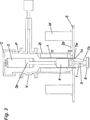
ここで図面を参照すると、図1は、構造物Sに導管を取り付ける第1の実施形態を示している。図1の分解図において、導管は、一方の末端部から間隔をあけて配置されている外部フランジ1fを有する円筒状パイプ1を備える。図5及び図6において明示されているように、パイプ1を取り付ける本装置は、平坦であり且つ矩形であるガイドプレート2pと、ガイドプレート2pの上側面から垂直に延出している中空孔を有するガイドチューブ2tとを備える。ガイドチューブ2tは、ガイドプレート2pに溶接されており、ガイドチューブ2tの孔よりも僅かに狭いガイドプレート2pにおける中心アパーチャ2aと同軸であり且つ中心アパーチャ2aを囲んでおり、そのため、半径方向に延出しているへりが、アパーチャ2aとチューブ2tの下側面との間に形成されている。ガイドチューブ2tの孔とアパーチャ2aとは同軸である。
Referring now to the drawings, FIG. 1 shows a first embodiment for attaching a conduit to a structure S. FIG. In the exploded view of FIG. 1, the conduit comprises a
ガイドチューブ2tの上端部は、バルブハウジングVの孔を閉塞するように構成されたバルブを担持するバルブハウジングVに対応するためにフランジが付けられている。バルブハウジングVは、その上側面にスペーサPを支持するために同様にフランジが付けられている。スペーサPの孔、バルブハウジングV、及び、チューブ2tは、互いに同軸であり且つアパーチャ2aと同軸であり、これらの部品の全ては、円形横断面を有する。
The upper end portion of the
プレート2pは、アパーチャ2aの両側に矩形のアパーチャを有し、そこを通って磁石Mが部分的に延出し、そこから磁石Mはプレート2pの下面に現れて通常は金属性である表面Sと係合し、さらに一時的に表面Sに接続することができる。磁石Mは、通常、切り替え可能であり、例えば電磁石とすることができ、磁性ドリルスタンドがこの目的のために使用されることができる。
The
ガイドプレート2p、ガイドチューブ2t、バルブハウジングV、及び、スペーサPは、構造物Sにパイプ1を送って接続するためのガイドアセンブリを一体的に備える。
The
パイプ1は、ガイドチューブ2tの孔内に配置され、パイプ1が構造物Sに接続される前にその最初の引き込み位置にあるときに、バルブハウジングV内にガイドチューブ2tを越えて延出している。パイプ1は、ガイドチューブ2tの孔よりも小さい直径を有し、通常、フランジ1fを用いて、場合によりその上端部においてスペーサ1sを用いて、そこから間隔をあけて配置されている。所望に応じて、フランジ1f及びスペーサ1sは、ガイドチューブ2tの孔の内側面に封止されることができ、これは必須ではないものの、場合により、Oリング又は他のシールを用いてバルブハウジングVに封止されることができる。パイプ1は、ガイドチューブ2t及びバルブハウジングVの孔内で軸方向に摺動可能である。スペーサPは、各端部において開放しており、ドリルステム5を回転させる回転モータ4が接続されたピストン3pとともに油圧シリンダ3を担持する取り外し可能なキャップCの形でキャップをその上端部に受け入れる。シリンダ3及びドリルステム5は、スペーサP、バルブハウジングV、及び、ガイドチューブ2tの孔を通って延出しており、ドリルステム5は、構造物Sを介して円形の孔を切削するのに適している回転ドリルビット6にその下端部において接続されている。図1において示されるように、ビット6は、ガイドプレート2pのアパーチャ2aを通過するようにその内部に嵌合して構成されている。ドリルビット6に接続される前に、ドリルステム5は、ドリフト7の形の拡張装置の内側孔を通過する。ドリフト7は、その最も広い地点においてパイプ1の外側外周と同じ形状を有し(この場合、それらは円形である)、パイプ1の内径に締まり嵌めされるように選択される。ドリフト7の最も広い地点は、その上側部分における先端7wであり、ドリフト7は、その下端部においてヘッド7hに向かって外径が次第に狭くなる。その上端部において、ドリフト7は、ドリフト7の先端7wにおける最も広い地点から延出している円筒部分7cを有する。この場合、円筒部分7cは、ドリフトの一体部分であるが、場合により、円筒状のスペーサで分離することができる。ドリフト7の内側孔において、ドリフト7の内側孔内でドリルステム5に対して支えるためにベアリングを収容するための2つの凹部があり、したがって、モータ4の運転中におけるドリルステム5の回転は、ドリフト7に伝達されない。
The
モータ4及びドリルステム5が取り付けられた油圧シリンダ3は、取り外し可能なキャップCに接続され、そして、ドリルステム5は、ドリフト7の内側孔に設けられ、その結果、ドリフト7は、図2において明示されているように、ドリフト7の円筒部分7cの上端縁がモータ4の下側面に当接するまでドリルステム5を上に摺動させる。そのとき、ドリフト7、ドリルステム5、モータ4、油圧シリンダ3、及び、取り外し可能なキャップCのアセンブリ全体は、図2に明示されているように、ドリフトがパイプ1の内側孔を下方に通るように、スペーサP、バルブハウジングV、及び、パイプ1の孔内に設けられる。一旦取り外し可能なキャップCがスペーサPの上側フランジに取り付けられると、ドリルステム5の下端部は、ドリフト7の下端部から突出し、その後、ドリルビット6は、それがプレート2pの上方に(又は逆らって)吊るされてアパーチャ2aの下側面を越えて延出しないように、ドリフト7の真下においてドリルステム5の下端部に取り付けられることができる。この最初のアセンブリ段階において、構造物Sが切削される前に、パイプ1は、図1において示される位置に固定されており、ドリフト7は、パイプ1の孔の軸に沿って自由に摺動可能である。
The hydraulic cylinder 3 to which the
パイプ1が構造物Sに取り付けられる準備ができたとき、アセンブリ全体は、構造物Sの上に降ろされるか、さもなければ案内され、磁石Mは、構造物Sの上にガイドフレーム2を一時的にクランプ締めするために取り付けるように作動される又は取り付けられるようになる。例えば吸引装置又は接着剤等、他の一時的な取り付け機構が、一部の場合において磁石の代わりに使用されることができる。ドリルビット6がプレート2pの平面の上方に間隔をあけて配置されており且つアパーチャ2aから外に延出していない状態で、モータ4は、ドリルステム5及びドリルビット6を回転駆動するために作動される。ドリルステム5の外側面とドリフト7の内側孔との間のベアリングは、トルクの伝達が、回転可能に固定されたままであり且つパイプ1の孔内に比較的硬く締まり嵌めされているドリフト7上のドリルステム5を回転させるのを防止する。一旦ドリルビット6が必要な切削速度で回転すると、油圧シリンダ3内のピストン3pは、モータ4をパイプ1の下方に押し込むように延伸される。モータ4の下側面がドリフト7の円筒部分7cの上側に当接することから、ドリフト7はまた、油圧シリンダ3の延伸によってパイプ1の孔の下方に軸方向に押し込まれる。必然的に、油圧シリンダ3の延伸はまた、パイプ1及びドリフト7の前方の構造物Sを介してドリルステム5及びドリルビット6を駆動し、これにより、パイプ1を収容するアクセス孔を切削する。
When the
図2において明示されているように、ドリルビット6の切削直径は、ぴったりとパイプ1の外径と一致するように選択され、その結果、パイプ1の下端部は、構造物Sを通って掘削された孔内にとまり嵌めされている。構造物Sを通るドリルビット6の下方への移動は、孔が切削され、最終的に、(切削されている孔よりも大きい直径を有する)フランジ1fがプレート2pの上側面に達するまで継続する。そのとき(図2において示される段階の直後)、ガイドチューブ2t内のパイプ1のさらなる軸方向移動は止められる。アパーチャ2aのへり上に担持されたフランジ1fを有するこの位置において、パイプ1の下端部は、それが構造物Sの下側面から突出するように、ビット6によってまさに掘削された構造物Sにおける孔の最初から最後まで延出している。
As clearly shown in FIG. 2, the cutting diameter of the
パイプ1のフランジ1fは、通常、フランジの外側面における周縁溝内に配置されたサークリップを有する。サークリップは、ガイドチューブ2tの内側面に逆らって拡張するように励起される。パイプ1がガイドチューブ2tの孔の下方に移動し、フランジ1fがプレート5sにおいてアパーチャ2aのへりに近付くのにともない、サークリップは、フランジ1fがアパーチャ2aのへりに達すると同時に、ガイドチューブ2tの内側面の溝と軸方向に並んで移動する。そして、フランジ1fがアパーチャ2aのへりに達し、パイプ1の最下端部が構造物Sにおける掘削されたアパーチャを介して延出しながら、サークリップは、ガイドチューブ2tの孔内で軸方向にフランジ及びパイプ1をロックするために、フランジの外側面の溝とガイドチューブ2tの内側面の溝との間において自由に拡張する。
The flange 1f of the
一旦フランジ1fがアパーチャ2aの端縁においてへりと係合し且つサークリップが拡張していると、シリンダ3内でのピストン3pの継続した移動は、現在固定されているパイプ1の下方にそれを軸方向に押し込むドリフト7上に軸方向力を及ぼし続ける。ドリフト7がパイプ1を軸方向下向きに移動するのにともない、ドリフト7における半径方向凹部においてバネに対して内側に押し込まれるせん断ピン7pが、せん断ピン7pがパイプ1にドリフト7をロックするためにスロット内のバネによって半径方向外側に延出する位置において、パイプ1の内側面における周縁スロットと軸方向に並べられるようになる軸方向位置にドリフト7が到達する。そのとき、本装置の形態は、ドリルビット6がアパーチャ2aから延出し且つドリフト7がちょうどパイプ1の下端部から突出し始める状態で図2と図3との段階の間である。
Once the flange 1f is engaged with the edge at the edge of the
油圧シリンダ3がピストン3pを下方に押し込み続けるのにともない、パイプ1にドリフト7を接続するせん断ピン7pは、ドリフト7がパイプ1の孔内で軸方向に自由に移動させて、油圧シリンダ3によって加えられた力の下で最終的にせん断する。ドリフト7のさらなる下方への移動は、パイプ1の端部からより小さい直径を持ちここでは構造物Sの下側面の下方に延出しているドリフトのヘッド7hを押し込む。
As the hydraulic cylinder 3 continues to push the
パイプ1の下端部は、頸部1nを有する。構造物Sの下側面を越えて突出しているパイプの最下端部において、へりが構造物Sの下側面を空にするように、頸部1nは、パイプ1の孔の内側周縁の周囲で半径方向内側に突出しているへりを備える。へりは、通常、その開口に隣接して、パイプ1の内側面上に置かれるはんだ又は溶接の連続的な又は不連続な線を備える。へりは、ドリフトのヘッド7hの外径よりも広いが先端7wよりも狭い内径を有する所定の距離だけ内側に延出している。これは、内側に延出しているへりを変形させることなくヘッド7hがへりを通過するのを可能とするが、ドリフト7の先端7wが周縁へりの内径よりも広いことから、それは、シリンダ3によって及ぼされる継続的な下向きの力により、最終的にはへりと係合するようになる。この係合の時点で、本装置は、パイプ1の頸部1nにおけるへりの内側面上に押圧する先端7wにおいてドリフト7の最も広い一部を持ち、実質的に、図3において示される形態にある。パイプ1の頸部1nは、ドリフト7よりも可鍛性であり、シリンダ3から加えられる継続的な力は、へりを介してドリフト7の先端7wを押し下げ、図4において示されるように、ドリフト7がパイプ1の頸部1nを完全に通過するまでドリフト7を半径方向外側に変形させる。ドリフト7がパイプ1の頸部1nを通過した後、パイプ1の頸部1nの外径は、半径方向外側に広げられ、アパーチャ2aよりも広い。アパーチャ2a、パイプ1、及び、ドリフト7の先端7wの寸法は、ドリフト7の通過がパイプ1の頸部1nの外径をしっかりと構造物Sに加締めるように、互いに精密公差内で選択される。
The lower end of the
ドリルステム5は、場合により、ドリルステム5がモータ4の下端部に対して上方に押圧されるとき、モータ4とドリルステム5との間においてトルクを伝達するスプライン5sを用いてドリルモータ4に接続されているが、ドリルビット6が下方から支持されないとき、スプライン5sは、ドリルモータ上のドリルステム5を保持せず、自由に下に落ちることができる。したがって、先端7wがパイプ1の頸部1nにおいてへりを通るとき、モータ4上にドリルステム5を保持する力が実質的に存在せず、ドリフト7、ステム5、及び、ビット6は、モータ4の下端部から構造物S内に落ちる。そのとき、ピストン3pは、パイプ1が頸部1nにおいて加締められることによってここでしっかりと構造物Sに固定されることから、パイプ1の孔からドリルモータ4を取り外すためにシリンダ3内に引き込まれることができる。通常、シリンダ3は、取り外し可能なキャップCが、次の作業の準備が行われるように油圧シリンダ3及びモータ4とともに表面に戻されることができる後に、その後に閉塞されるバルブの上方の高さにモータ4を引き込める。そして、バルブハウジングVの上側台座は、開放したバルブを介して回収用のさらなる導管内を通りその後にパイプ1の孔内にアパーチャ2aを介して逆流する可能性がある流体を構造物から除去するためのさらなる流体導管に接続されることができる。
In some cases, when the
所望の場合、ガイドチューブ2t及びガイドプレート2pは、構造物Sにアセンブリを固定する磁石M及びサークリップを用いて適所にとどまることができる。いくつかの実施形態において、ドリフト7とパイプ1との間のせん断ピン又はシール、及び、フランジ1fとガイドチューブ2tとの間のサークリップは、任意であり、ドリフト7の先端7wがパイプ1の孔内で摩擦嵌めし、同様に、フランジ1fがガイドチューブ2tの孔内で摩擦嵌めした状態で、省略されることができる。そのような実施形態において、一旦パイプ1の頸部が構造物に完全に加締められると、パイプ1と構造物Sとの間の構造的接続のみのようにパイプ1の頸部における加締めを残しながら、ドリフト7、ドリルステム5、及び、ドリルビット6は、構造物S内に落とされ、モータ4は、閉塞されたバルブの上方に引き込められ、磁石Mは取り外されることができる。
If desired, the
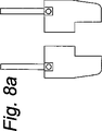
図7a及び図7bは、図7aにおいて示される半径方向に拡張された形態と図7bにおいて示される半径方向に収縮された形態との間で、半径方向に拡張可能であるドリフトの別のデザインを示している。図8a及び図8bにおいて示されているように、ドリフトの別の構造は、ドリルモータ4を介したピストン3pからの力を伝達するために別個の円筒状のスペーサーリングに逆らって支えるために、ドリフトの上側面におけるスロット内に収容されているベアリングレースを有することができ、これにより、モータ4によってドリルステム5に加えられるトルクからドリフト7を分離する。図9において示されるように、ドリフトのヘッドは、場合により、ドリフト上の特定の回転位置における切削圧力を高めるために一様でない楕円形の(又は他の)形状を有することができ、パイプ1の頸部を介してドリフトを押圧するためにシリンダ3から必要とされる力を低減することができる。図10は、図1〜図4において記載されたドリフトと同様のドリフトのさらなる構造を示しているが、先端におけるせん断ピンを省略している。ベアリングは、場合により、ドリフトの中心を通る孔の上端部及び下端部においてスロット内に挿入されることができる。
7a and 7b show another design of drift that is radially expandable between the radially expanded configuration shown in FIG. 7a and the radially contracted configuration shown in FIG. 7b. Show. As shown in FIGS. 8a and 8b, another structure of drift is to support against a separate cylindrical spacer ring to transmit force from the
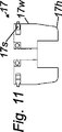
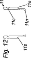
図11及び図12は、広い上側の先端17wと、比較的狭い下側のヘッド17hと、ドリルステム5に逆らって支えるように内側(又は上側)に面したベアリングを有する中心孔と、半径方向にバネが付いたせん断ピン17sの構成とを有するドリフト17の変更されたデザインを示している。ドリフト17は、先の実施形態におけるパイプ1と同様の機能を果たす接続スリーブ11を使用するのに適している。接続スリーブ11は、図12において示されており、スリーブ11の孔内に半径方向内側に突出しているへり11lを有する頸部11nを有する。スリーブ11はまた、その外側面から半径方向外側に延出している肩部11sを有する。スリーブ11はまた、ドリフト17上のせん断ピン17sを収容する周縁スロット11cを有する。
11 and 12 show a wide
図13は、ドリルビット6の上側面と係合するドリフト17の別個の図である。ドリフト17は、ビット6がその下部で回転するときパイプ1内で固定されて保持されている。
FIG. 13 is a separate view of the
図14は、スリーブの内側面と係合し、且つ、変更されたドリフトの先端が頸部を拡張し始める前にパイプ1で内軸方向下向きにそれを押圧するように構成されたヘッドにおけるステップを有するドリフトの別のデザインを示している。
FIG. 14 shows a step in the head that engages the inner surface of the sleeve and is configured to push it inwardly in the
特定の実施形態において、パイプ1の加締め後に、及び、ガイドチューブ2t及びガイドプレート2pの取り外し後に、取り付けられたパイプ1は、パイプ1の頸部1nがドリフト7の下方への移動によって外側に加締められた状態で、図15において示される形態を有する。
In certain embodiments, after caulking of the
図16は、変更されたドリフト17及びスリーブ11を使用するさらなる実施形態を示している。図16の実施形態は、上述されたものと同じ方法でドリルモータ14、ドリルステム15、及び、ドリルビット16上に力を及ぼすピストン13pを有する油圧シリンダ13を含む中心孔を有するフランジ付きのパイプ10を固定する。図16の実施形態において、パイプ10のフランジは、磁石Mを用いて一時的に構造Sに接続され、ビット16及びその上方の関連する機器は、切削されることになる構造物Sの上方のフランジ付きのパイプ10の孔内に引き込められる。最初に、ピストン13pがシリンダ13の先端まで引き抜かれ、ドリフト17がスリーブ11の上方に配置される。スリーブ11の下方に、ドリルビット16がパイプ10の孔のちょうど開放端部内で配置される。スリーブ11は、最初に、パイプ10の孔内に引き抜かれ、少なくともドリルビット16の距離だけ孔の開放端部から間隔をあけて配置される。パイプ10が構造物Sに固定されることになるとき、モータ14は、上述されたように、ビット16を回転するように作動され、ピストン13pは、構造物Sを介してビット16を駆動するように延伸される。ビット16によって切削された孔の直径は、スリーブ11のヘッド11nの通過を可能とするのに十分であり、モータ14の下側面は、モータ14がドリフト17の先端17wにおいてスリーブ11の上側面と係合するまでドリフト17を下方に駆動し、ビット16によって切削された孔を介してフランジ付きのパイプ10の孔の下方にスリーブ11を押し込む。特定の実施形態において、ヘッドの下端部における正方形のへりがスリーブ11の上端縁とより完全な初期接触をなすように、図14のドリフトの実施形態が使用されることができる。
FIG. 16 shows a further embodiment using a modified
したがって、ドリフト17は、スリーブ11の外側面における肩部11sが構造物Sの上側面と係合するまで、構造物Sを介して切削された孔を介して下方にスリーブ11を押し込む。肩部11sは、孔よりも大きい直径を有し、孔を通過することができないので、ピストン13pのさらなる延伸は、これ以上スリーブを移動しないが、スリーブ11の内側孔を介して軸方向下向きにドリフト17を駆動し、これにより、半径方向外側にドリフト17を拡張する。この動作に沿ったいくつかの地点において、ドリフト17の外側面におけるせん断ピン17sは、スリーブ11の内側面の周縁リング17c内で係合し、これにより、スリーブ11にドリフト17をロックする。
Accordingly, the
さらなる下方への力がドリフト17上のピストン13pによって及ぼされ、最終的にピン17sをせん断し、スリーブ11の孔を介して下方にドリフト17を迅速に移動させる。このスリーブ11の頸部11nを介したドリフト17の幅の広い先端17wの下方への移動は、構造物Sの下側面の下部において半径方向外側に頸部11nを加締め、これにより、構造物Sにスリーブ11をしっかりと加締める。
A further downward force is exerted by the
ドリフト17がスリーブ11を介して完全に通過した後、ドリフト17は、上述されたものと同じ方法でモータ14の下側面からドリルステム15及びビット16とともに落ちることができ、後の動作のためにモータ14及びピストン13pの収縮を可能とする。既に述べたように、磁石Mは、この時点で場合により取り外されることができ、又は、フランジ付きのパイプ10用の追加の固定手段として適所に残すことができる。
After the
図16と同様の特定の実施形態において、サークリップ又は他の固定手段は、フランジ付きのパイプ10の孔の内側面にスリーブ11を固定するために使用されることができ、Oリングが、場合により、スリーブ11とパイプ10との間に液体シールを形成するために設けられることができる。
In a specific embodiment similar to FIG. 16, a circlip or other securing means can be used to secure the
パイプ21を接続する装置のさらなる実施形態が、図17及び図18において示されており、取り付けられたパイプが、この方法にしたがって図19において示されている。
A further embodiment of the device for connecting the
図17の実施形態において、ガイドチューブ22tには、上述されたように、磁石Mによって一時的に表面S上に保持されたフランジ22pが設けられている。ガイドチューブ22tの孔は、真っ直ぐであり、その下端部においてへりを有しておらず、したがって、構造物Sに取り付けられることになるパイプ21のフランジ21fは、一旦孔が切削されると構造物Sの外側面上に直接押圧される。変更された実施形態は、上述されたように、バルブハウジングVとスペーサPとを有する。駆動シャフト25を駆動するモータ24、及び、ピストン23pを駆動する油圧シリンダ23もある。しかしながら、図17の変更された実施形態において、ドリフト27は、ドリルビット26の上方であるがパイプ21の頸部21nの下方において、装置に搭載されているが、パイプ21の内側孔よりも狭いドリフト27のヘッド27hが、パイプ21の孔の内部に上方を向いて配置されて、且つ、頸部21nの領域においてパイプ21の孔よりも広いドリフト27の先端27wが、パイプ21の下方且つ外部に配置されてもよい。一旦キャップCがスペーサPの上側面上に固定されると、油圧シリンダ23は、パイプ21の孔を介して上方にドリフト27を引っ張るように動作し、キャップの上方に配置されたモータ24は、ドリルビット26と係合する前に、油圧シリンダ23、パイプ21、及び、ドリフト27を通過する細長いシャフト25を介してビット26を動作する。
In the embodiment of FIG. 17, the guide tube 22t is provided with a
動作時、図17及び図18の実施形態は、組み立てられてガイドチューブ22t、バルブが開放されたバルブハウジングV、及び、スペーサP内に送り込まれ、キャップCは、スペーサPの上側面上にアセンブリをロックするように固定される。その後、モータ24は、構造物Sの面を介して孔を切削するためにドリルステム25を駆動してビット26を回転するように係合される。油圧ピストン23pは、構造物Sの面を介したドリルビット26の下方への移動を駆動するために、最初にシリンダ23の途中に設置されることができ、このために必要とされる反力は、構造物Sにフランジ22pを固定する磁石Mによって保持されることができる。一旦ドリフト27及びドリルビット26が構造物Sを介して進むと、パイプ21の外側面におけるフランジ21fは、ドリルビット26によって切削される孔よりも狭いことから、構造物Sの上側面と係合する。この位置において、パイプ21の頸部21nは、構造物Sの下側面よりも下方に軸方向に突出している。その後、モータ24は停止されることができ、油圧シリンダ23は、パイプ21の孔内で軸方向上向きにドリルステム25を引っ張るように逆に動作されることができ、したがって、ドリフト27のヘッド27hは、パイプ21の頸部21n内に押し上げる。ドリフト27のヘッド27hは、頸部21nの内径よりも狭いものの、頸部21n内へのドリフト27の継続した移動は、ドリフト27の外側面が頸部21nの下側面と係合して半径方向外側に頸部を変形する地点に到達する。最終的に、先端27wにおけるドリフト27の最も広い一部は、パイプ21の頸部21nを加締めるように上方に引っ張られ、これにより、構造物Sにしっかりと接続する。
In operation, the embodiment of FIGS. 17 and 18 is assembled into the guide tube 22t, the valve housing V with the valve open, and fed into the spacer P, and the cap C is assembled on the upper side of the spacer P. Fixed to lock. The
場合により、ドリフト27、頸部21n、及び、ドリルビット26によって形成される構造物Sを通る孔の寸法は、(内側へりを有する又は有しない)頸部21nの加締めが完了した後にドリフト27が頸部21nの最初から最後まで上向きに通り且つパイプ21の中心孔を介して回収されることができるように選択されることができる。あるいは、頸部21nが構造物Sにパイプ21を固定するために十分な範囲まで加締められた後、ドリフト27、ドリルステム25、及び、ドリルビット26は、上述されたような方法で、スプラインによってモータ24から取り外されることができ、構造物内に落ちることができる。そして、磁石Mは、取り外されてもよく、油圧シリンダは、バルブを閉塞するのを可能とするためにスペーサP内に引き込まれてもよい。あるいは、磁石Mは、油圧シリンダ23及びモータ24が他の作業のために表面に回収された後に適所にとどまることができるガイドチューブ22t用の追加の固定要素として残すことができる。あるいは、バルブは、パイプ21に対するさらなる導管の制御された取り付け、及び、図19において示されるように頸部21nにおいて加締めることによって構造物Sに取り付けられたパイプ21のみを残すようにアセンブリ全体の取り外しを可能とするように使用されることができる。
Optionally, the size of the hole through the structure S formed by the
この実施形態は、例えば、構造物を膨らませるための、さもなければ構造物に浮力を与えるための構造物内への圧縮された空気の注入等、流体の注入用のパイプの取り付けに特に適している。 This embodiment is particularly suitable for mounting pipes for injecting fluids, for example, injecting compressed air into the structure to inflate the structure or otherwise provide buoyancy to the structure. ing.
パイプ31を接続する装置の同様の実施形態が、図20乃至図22において示されている。
A similar embodiment of the apparatus for connecting the
図20の実施形態において、ガイドチューブ32tには、上述されたように、磁石Mによって一時的に表面S上に保持されたフランジ32pが設けられている。ガイドチューブ32tの孔は、ドリルビット36を受け入れるアパーチャとともに、その下端部においてへりを有する。構造物Sに取り付けられることになるパイプ31のフランジ31fは、アパーチャ内に締まり嵌めしてへりの外側面上に直接フランジ外形の上側部分と係合するように形成されている。図20の実施形態は、上述されたように、バルブハウジングV及びスペーサPを有する。駆動シャフト35を駆動するモータ34、及び、ピストン33pを駆動する油圧シリンダ33もある。先の実施形態のように、図20の変更された実施形態において、ドリフト37は、ドリルビット36の上方であるがパイプ31の頸部31nの下方において装置に搭載されており、パイプ31の内側孔よりも狭いドリフト37のヘッド37hが、パイプ21の孔の内部に上方を向いて配置され、且つ、頸部31nの領域においてパイプ31の孔よりも広いドリフト37の先端37wが、パイプ31の下方且つ外部に配置されてもよい。一旦キャップCがスペーサPの上側面上に固定されると、油圧シリンダ33は、パイプ31の孔を介して上方にドリフト37を引っ張るように動作し、キャップの上方に配置されたモータ34は、ドリルビット36と係合する前に、油圧シリンダ33、パイプ31、及び、ドリフト37を通過する細長いシャフト35を介してビット36を動作する。
In the embodiment of FIG. 20, the guide tube 32t is provided with a
動作時、図20の実施形態は、組み立てられてガイドチューブ32t、バルブが開放されたバルブハウジングV、及び、スペーサP内に送り込まれ、キャップCは、スペーサPの上側面上にアセンブリをロックするように固定される。その後、モータ34は、構造物Sの面を介して孔を切削するためにドリルステム35を駆動してビット36を回転するように係合される。油圧ピストン33pは、構造物Sの面を介したドリルビット36の下方への移動を駆動するために、最初にシリンダ33の途中に設置されることができ、このために必要とされる反力は、構造物Sにフランジ32pを固定する磁石Mによって保持されることができる。一旦ドリフト37及びドリルビット36が構造物Sを介して進むと、パイプ31の外側面におけるフランジ31fは、孔のへりの上側面と係合する。この位置において、パイプ31の頸部31nは、構造物Sの下側面よりも下方に軸方向に突出している。その後、モータ34は停止されることができ、油圧シリンダ33は、パイプ31の孔内で軸方向上向きにドリルステム35を引っ張るように逆に動作されることができ、したがって、ドリフト37のヘッド37hは、パイプ31の頸部31n内に押し上げる。ドリフト37のヘッド37hは、頸部31nの内径よりも狭いものの、頸部31n内へのドリフト37の継続した移動は、ドリフト37の外側面が頸部31nの下側面と係合して半径方向外側に頸部を変形する地点に到達する。最終的に、先端37wにおけるドリフト37の最も広い一部は、パイプ31の頸部31nを加締めるように上方に引っ張られ、これにより、構造物Sにしっかりと接続する。
In operation, the embodiment of FIG. 20 is assembled and fed into the guide tube 32t, the valve housing V with the valve open, and the spacer P, and the cap C locks the assembly onto the upper side of the spacer P. To be fixed. The
場合により、ドリフト37、頸部31n、及び、ドリルビット36によって形成される構造物Sを通る孔の寸法は、(内側へりを有する又は有しない)頸部31nの加締めが完了した後にドリフト37が頸部31nの最初から最後まで上向きに通り且つパイプ31の中心孔を介して回収されることができるように選択されることができる。あるいは、頸部31nが構造物Sにパイプ31を固定するために十分な範囲まで加締められた後、ドリフト37、ドリルステム35、及び、ドリルビット36は、上述されたような方法で、スプラインによってモータ34から取り外されることができ、図22において示されるように、構造物内に落ちることができる。そして、磁石Mは、取り外されてもよく、油圧シリンダは、バルブを閉塞するのを可能とするためにスペーサP内に引き込まれてもよい。あるいは、磁石Mは、油圧シリンダ33及びモータ34が他の作業のために表面に回収された後に適所にとどまるガイドチューブ32t用の追加の固定要素として残すことができる。
Optionally, the size of the hole through the structure S formed by the
図23〜図29は、ドリルステムの異なるデザインを示している。図23は、構造物内へのドリフトの落下を可能とするように構成されていない固形ドリルステムを示している。図24は、変更されたステムを示しており、ステムのヘッドは、モータが逆転するときにヘッド及びシャフトを離脱するように構成されたねじ山によってシャフトに接続されている。図28及び図29は、場合によりボールねじを使用している適切なヘッド及びねじ山の異なる実施形態の拡大図を示している。図26及び図27は、モータによって高いトルクを受けたときに疲労して機能しなくなり且つドリフトが構造物内にステムの下側部分とともに落ちるのを可能として分離するように構成された、その下端部に隣接する脆弱点を有する犠牲的なドリルステムの動作及び分離の順次的な図を示している。 Figures 23-29 show different designs of drill stems. FIG. 23 shows a solid drill stem that is not configured to allow drift to fall into the structure. FIG. 24 shows a modified stem, where the head of the stem is connected to the shaft by a thread configured to disengage the head and shaft when the motor reverses. Figures 28 and 29 show enlarged views of different embodiments of suitable heads and threads, optionally using ball screws. FIGS. 26 and 27 show their lower end configured to fatigue and fail when subjected to high torque by the motor and to allow the drift to fall with the lower portion of the stem into the structure. FIG. 4 shows a sequential view of the operation and separation of a sacrificial drill stem having a weak point adjacent to the part.
図30は、構造物Sに小さい直径のパイプ40を接続するのに使用される、さらに変更された実施形態を示している。これは、特に、例えば2インチ孔の狭いパイプに適しており、パイプ40の孔内でドリルアセンブリを収容するのには適していない。この実施形態において、油圧シリンダ43は、パイプに接続された側面ブラケット上に配置されており、スラストベアリングによってドリルステム45と係合する。ドリルモータ44は、スラストベアリングの上方に配置されている。サークリップ49によってパイプ40に接続されているスリーブ41は、構造物Sに隣接するパイプ40の孔の下端部に設けられており、その初期位置において、スリーブ41及びその下方のドリルビット46は、パイプのフランジが構造物Sの外側面に接続されたとき、パイプ40の孔内に、スラストベアリング上に作用する油圧シリンダ43によって回収される。スリーブ41がパイプ40の孔内に回収されるその上側部分において、サークリップ49は、スリーブ41の外側面における環状溝内に押圧され、スリーブ41がパイプ40の孔内で自由に摺動するのを可能とする。パイプ40のフランジが磁石Mによって構造物Sの外側面に取り付けられたとき、モータ44は、ドリルビット46を回転させるように始動され、油圧シリンダ43は、ドリルステム45、スリーブ41、及び、ドリルビット46をパイプ40の孔内での軸方向下向きに駆動するために作動され、したがって、ビット46は、構造物Sの外側面を介して切削する。サークリップ49がスリーブ41の外側面における環状スロット内に半径方向に押圧されるのにともない、スリーブ41は、パイプ40の孔内で軸方向に自由に摺動することができる。油圧シリンダ43が構造物Sの外側面に向かってパイプ40の孔の下方にドリルビット46を押し込むために延伸しているとき、ドリフトのヘッド47hは、スリーブ41の孔内に短く延伸し、ヘッド47hのテーパが付けられた側面がスリーブ41の孔のリムの内端縁と係合するとき、ドリフト47は、パイプ40の孔の下方に軸方向にスリーブ41を移動し始める。油圧シリンダ43によって駆動される下方への移動は、最終的に、構造物Sを介してドリルビット46を押し込み、ドリフト47のヘッド47hは、ドリルビット46によって形成された孔内に縮小した直径を有するスリーブ41の下側部分を押し込む。スリーブ41の外側面における肩部が構造物の外側面に対して押圧されるとき、スリーブ41は、パイプ1の孔の下方へのさらなる移動が防止される。この段階において、スリーブ41は、スリーブ41の頸部41nが構造物Sの内側面から突出した状態で、図30において示される位置にある。先の実施形態のように、頸部41nは、スリーブ41の孔内に半径方向内側に突出しているへりを有し、へりは、ヘッド47hよりも広いが、ドリフト47の先端47wよりも狭い。
FIG. 30 shows a further modified embodiment used to connect a
スリーブ41における外側肩部が構造物Sの外側面と係合しているとき、サークリップ49は、パイプ40の内側面における環状溝と軸方向に並べられ、したがって、スリーブ41がこの軸方向の位置に到達したとき、パイプ40の孔内で、サークリップ49は、環状溝内で拡張し、パイプ40にスリーブ41をロックする。
When the outer shoulder of the
油圧シリンダ43の下方へのさらなる移動は、スリーブ41を移動しないが、スリーブ41の孔内にドリフト47を駆動し、図30において示された地点において、バネ及びドリフト47の半径方向の孔によって付勢される一対のせん断ピン47pがスリーブ41の孔の内側面における環状溝と係合し、これにより、ドリフト47をスリーブ41にロックする。
Further downward movement of the hydraulic cylinder 43 does not move the
この地点において、油圧シリンダ43は、ピン47pをせん断し、且つ、スリーブ41の内側孔の最初から最後までドリフト47を駆動するために、さらに延伸されることができる。一旦ドリフト47の先端47wがスリーブ41の頸部41nを通過すると、頸部41nにおけるへりは、構造物Sの内側面の下方に頸部41nを変形させるように半径方向に押し出し、これにより、スリーブ41を構造物Sに加締める。サークリップ49は、スリーブ41とパイプ40との間の機械的接続を維持し、その段階において、ドリフト47及びビット46は、ドリルステム45の下端部におけるスプライン結合の一方向接続から落ちたまま、磁石M、モータ44、油圧シリンダ43、及び、ドリルステム45は、上述されたように取り外されることができる。その後、パイプ40と構造物Sとの間の機械的接続は、加締められたスリーブ41の頸部41nとサークリップ49とによって維持される。
At this point, the hydraulic cylinder 43 can be further extended to shear the pin 47p and drive the drift 47 from the beginning to the end of the inner bore of the
注目すべきは、せん断ピン47pがこの実施形態及び他の全ての実施形態において任意であるということである。また、所望に応じて流体の流れを規制するために、Oリングシール41sが、場合により、スリーブ41とパイプ40との間に(及び他の実施形態において)設けられることができる。この実施形態のある変形例において、磁石Mは、パイプ1と構造物Sとの間における追加の機械的接続を形成したままである。
It should be noted that the shear pin 47p is optional in this and all other embodiments. Also, an O-
図31は、大孔パイプ51が構造物Sに接続されることになる場合のさらなる実施形態を示している。大孔パイプ51は、2つの磁石Mを収容するように孔開けされたフランジを有する。磁石Mは、フランジの上側面に支えて構造物Sに向かって且つ構造物Sから離れてパイプ51を移動するように軸方向力が加えられるのを可能とする油圧シリンダ58を支持する。上述されたようにキャップC上に搭載される油圧シリンダ53は、パイプ51の孔内に設けられ、上述されたように、ドリルステム55によってドリフト57に接続する。ドリフト57の下方において、ドリルビット56は、パイプ51の頸部51nを収容するように構造物Sを介して孔を切削するために、油圧シリンダ53の下方においてモータ54に接続されたドリルステム55によって回転される。
FIG. 31 shows a further embodiment where the
図31及び図32の実施形態において、モータ54は、ドリルビット56を回転させるように駆動される。切削作用のための下向きの力は、場合により、磁石Mとパイプ51のフランジとの間において作用する油圧シリンダ58によって与えられ、したがって、ドリルビット56は、構造物Sを介してパイプ51の頸部51n用のアクセス孔を強制的に切削させられる。場合により、ドリルビット56の軸方向移動のためのいくつかの駆動力はまた、頸部51nが空になった構造物Sの下側面を有する後までドリルビット57が頸部51nを介して駆動されないという条件で、油圧シリンダ53によって与えられることができる。大抵の実施形態において、構造物Sを介してドリルビット56を押し込む力が、アセンブリ全体を押し下げる外部のシリンダ58によって与えられ、したがって、頸部51nは、ドリルビット56によって切削された孔を介して押し込まれる。一旦パイプ51のフランジが構造物Sの外側面にぴったり接触し、且つ、パイプ51の頸部51nが構造物Sの内側面から突出すると、油圧シリンダ53は、パイプ51の頸部51nを介してドリフト57を駆動するために作動されることができ、これにより、頸部51nの内側面におけるへりを半径方向に拡張し、構造物Sに頸部51nを加締める。頸部51nが構造物Sに十分に加締められた後、ドリルステム55及びドリフト57は、ドリルステム55とモータ54との間におけるスプラインの離脱によって構造物内に落ちるのを可能とされることができ、アセンブリ全体は、パイプ51が構造物Sに加締められたまま表面に回収されることができる。
In the embodiment of FIGS. 31 and 32, the
この実施形態の任意の変形例において、ピストン53及び典型的なモータ54は、シリンダ53についてのケーシングにスプライン結合されることができる。また、ベアリングは、通常、ドリフト57とドリルステム55との間に設けられることができる。
In any variation of this embodiment, the
図33は、典型的な油圧シリンダ63についての構成を示している。通常、Gyrotor(商標)モータ64は、ピストン63pの下側面にボルト留めされ、場合により、モータ64とシリンダ63のケーシングとの間における相対的な回転を防止するために、シリンダ63がスプライン結合される。油圧ホースは、モータ64に動力を供給するためにシリンダ63の上側部分を経由することができ、適切なポートが、この目的のためにピストン63pを介して設けられることができる。
FIG. 33 shows a configuration for a typical
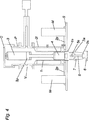
ここで、図34〜図48を参照する。第7の実施形態は、特に、2つの外板、すなわち、船舶の船殻S1の外壁等の外側の外板と、外側船殻S1から間隔をあけて配置され且つ回収されるべき流体(例えば油)を含むオイルタンクS2等の内側の外板とを有する構造物に導管を取り付けるのに有益である。通常、船舶等における外側及び内側船殻間の空間は、約1mであるが、恒常的要因ではない。図34においてみられるように、導管は、末端部から間隔をあけて配置された外部フランジ71fを有する円筒状パイプ71と、先の実施形態と同様のガイドプレート72とを備える。ガイドチューブ72tを有するガイドプレート72は、72sにおいてその内側面上に環状シールを有し、上述されたように、磁石又は他の接続を介して一時的に船殻S1に取り付けるように構成されている。
Reference is now made to FIGS. In particular, the seventh embodiment has two outer plates, ie, an outer outer plate such as an outer wall of the ship's hull S1, and a fluid to be arranged and separated from the outer hull S1 (for example, It is useful for attaching the conduit to a structure having an inner skin such as an oil tank S2 containing oil. Usually, the space between the outer and inner hulls of a ship or the like is about 1 m, but this is not a constant factor. As seen in FIG. 34, the conduit comprises a
ガイドプレート72の上端部は、パイプ71を受け入れるように開放されており、構造物S1、S2にパイプ71を接続する。
The upper end portion of the
パイプ71は、既に述べたように、ガイドチューブ72tの孔内に堅く締まり嵌めされ、ガイドチューブ72tの孔よりも極めて僅かに小さい直径を有しており、上述したように軸方向に摺動可能である。パイプは、72sにおいてシールよってガイドチューブ72tの孔内で封止される。
As already described, the
パイプ71は、通常はフランジ71fを介してパイプ71の下側部分に取り付けられたバルブハウジングVを組み込んでいる。パイプ71の上端部は、ドリルステム75を回転する回転モータ74に接続されたピストン73pとともに油圧シリンダ73を担持する同軸の上側部分71uを有する。(図42乃至図45においては明瞭に示されていないが、図46及び図47において示されている)Y字片71yは、上側部分71uから斜めに分岐し、パイプ71が構造物S1/S2に取り付けられたとき、流体を回収するための導管として使用する役目を果たす。シリンダ73及びドリルステム75は、パイプ71及びガイドチューブ72tの孔を介して延出しており、ドリルステム75は、構造物Sを介して円形孔を切削するのに適している回転ドリルビット76にその下端部において接続されている。Y字片の上方のパイプ71の上側部分71uは、掘削機構を収容する。ビット76は、ガイドプレート72のアパーチャ内に締まり嵌めしており、アパーチャを通過するように構成されているが、パイプ71の外径よりも大きい直径を有し、したがって、パイプ71は、好ましくはそれらの間においてぴったりと嵌合しながらビット76によって切削された孔を通過することができる。ドリルステム75は、先に説明されたドリフト7と同様のドリフト77を介してドリルビット76に接続する。
The
シリンダ73は、場合によりロッド82とブリッジ83との間における取り外し可能なコネクタを用いてそれらの上端部においてブリッジ83によって一体的に接続された一対の平行なロッド82を備えるフレーム81によってガイドプレート72上に支持されている。ロッドは、場合により、ロッド82とプレート72との間において取り外し可能な相互接続を可能とするガイドプレート72上の取り外し可能なコネクタ(図示しない)にそれらの両端部において接続されている。いくつかの実施形態において、ロッド82は、プレート72に溶接されることができる。フレーム81は、シリンダ73を安定させ、孔の掘削中にガイドプレート72及び/又は船殻S1にシリンダ73を固定する。
The
場合により、パイプ71の下端部は、外側に励起され且つパイプ71の外側面とぴったり重なるように環状溝内に圧縮状態に保持されることができるバネクリップ86(又はサークリップ若しくはバネくさび)を収容するその外側面に環状溝(図48を参照)を有する。
In some cases, the lower end of the
組み立て中に、取り付けられたモータ74、ドリルステム75、及び、ドリフト77とともに油圧シリンダ73が一体的に接続され、シリンダ73の上部がブリッジ83に取り付けられ、その後、全ての取り付け具とともにシリンダ73が上側パイプ部分71uの内側孔の上部に設けられ、したがって、ドリフト77は、パイプ71の内側孔を介して下方に通過し、ロッド82は、パイプ71の外側へ下方に通過する。
During assembly, the
パイプ71の外側面上のバネクリップ86は、パイプ71がガイドチューブ72tの孔に提供される前に半径方向に圧縮され、その後、バネクリップ86は、ガイドチューブ72tの孔内にとどまる限り、ガイドチューブ72tの内側面によって環状溝内に圧縮状態に保持される。
The spring clip 86 on the outer surface of the
ロッド82は、ガイドプレート72の上側面を接続する又は上側面に溶接される。ユニットが配置される前に、パイプ71と同じ直径を有し、したがって、その孔内に収容できないドリルビット76は、ガイドプレートが表面に取り付けられる前に、ガイドプレート72におけるアパーチャの下端部に設けられ、ドリフト77の下方においてドリルステム75に取り付けられる(又は、いくつかの変形例において、ドリルビット76は、ドリフトアセンブリにおけるベアリング上に支持されたシャフトに取り付けられることができる)。一旦ドリルビット76がドリフト77又はドリルステム75に取り付けられると、ユニットは配置されることができ、ガイドプレート72は、例えば上述されたように磁石を用いて、一時的に外側船殻S1に取り付けられる。この段階において、アセンブリは、ドリルビット76がパイプ71の下端部と船殻S1の外側面との間においてガイドチューブ72t内に配設された状態で、ここで図42において示される形態にある。ドリルビット76は、先の実施形態について上述されたように、取り外し可能な方法で拡張装置の端部上に保持されることができる。
The
ロッド82は、ガイドプレート72上の油圧シリンダ73を安定させ且つ少なくとも内側船殻S2の加締め中にそれをそこで固定するように、ロック機構の一部を形成する。図39において最もよく示されるように、ロッド82は、その延伸がロッド82を中心にアーム84を回動させることができる小さい油圧シリンダ85によってそれらの両端部において一体的に接続されたレバーアーム84上の回動点として作用する軸方向孔を通過している。レバーアーム84は、ロッド上に回動可能に規制されており、導管のフランジ71fに接続された通常はU字状のブラケット(図示しない)によって導管に対して軸方向移動に反して係留されている。したがって、アーム84は、フランジ71fに対してロッド82を中心に回動可能に移動することができるが、フランジ71fに対して軸方向に移動することができない。しかしながら、それらは、ロッド82に対して軸方向に選択的に移動することができる。アーム84は、図41において示されるロック解除の形態を有し、この場合、小さい油圧シリンダ85は延伸され、また、アームは、ロッド82を中心に互いに外側に回動され、図39及び図40において示されるロックされた形態の場合、小さい油圧シリンダ85は引き込まれ、レバーアーム84の自由端は、ロッド82の回動点を中心に互いに向かって移動する。この形態変化は、レバーアームにおけるロックを開始し、それらがロッド82に関して軸方向に摺動するのを防止する。アームのロック用の機構は、一般的であり、くさび状の窪み内を通るアーム82におけるカム又は係留ボールベアリングで十分である。
The
その後、モータ74は、ドリルステム75及びドリルビット76を回転駆動するように作動する。一旦ドリルビット76が必要な切削速度で回転されると、油圧シリンダ73内のピストン73pは、外側船殻S1を介して切削するように、ガイドチューブ72tを介して、パイプ71、ピストン73p、モータ74、ドリフト77、及び、ビット76のアセンブリ全体を一体的に軸方向に押し下げるように延伸される。ロッド82がガイドプレート上に且つ外側船殻S1に対してそれを介して固定されるのにともない、レバーアーム84は、小さい油圧ピストン85が図41において示されるロック解除の形態で延伸される限り、自由にロッド82を滑り降りる。通常、ドリルビット76は、場合により、モータ74の通常の時計回りの回転中にビット76を保持する逆ねじ又はボールねじによってドリルステム75上に保持される。
Thereafter, the
外側船殻S1の貫通中に、ドリフト77は、パイプ71を介して軸方向に移動されないが、代わりに、アセンブリ全体とともに移動するので、パイプ71は、外側船殻S1に加締められない。
During penetration of the outer hull S1, the
一旦パイプ71の底が、船殻S1、S2間の空隙内へとガイドチューブ72t及び外側船殻S1を通過すると、本装置は、図43において示される形態にある。そのとき、バネクリップ86は、ガイドチューブ772tの内側面によって溝内でもはや圧縮状態に保持されず、したがって、バネクリップ86は、図48において示されるように、ドリルビット76の切削直径よりも大きい直径まで溝内で半径方向外側に拡張する。
Once the bottom of the
ドリルビット76の切削直径は、ぴったりとパイプ71の外径と一致するように選択され、その結果、パイプ71の下端部は、構造物S1、S2を介して掘削された孔内に締まり嵌めされている。しかしながら、ドリフト77は、内側船殻S2の貫通後までパイプ内で軸方向に駆動されないので、パイプ71は、内側船殻S2に向かって外側船殻S1における孔を介して軸方向に自由に移動する。
The cutting diameter of the
パイプ71が内側船殻S1に到達したとき、ドリルビット76は、内側船殻S1を通って切削し始め、パイプ71は、内側船殻S2における孔を通って延出している頸部71nを有するパイプ71の端部を有する図44において示されるステージまで、これまでのように内側船殻S2を介して軸方向に移動する。内側船殻S2に向かうアセンブリ及びパイプ71の下方への移動は、(内側船殻S2内で切削されている孔よりも大きい直径を有する)半径方向に励起されたバネクリップ86が内側船殻S2の外側面上に達するまで継続する。(図44において示される)そのとき、パイプ71(及び頸部71n)の最も内側の端部は、内側船殻S2における孔の内側端部の下方に延出しており、ガイドチューブ72t内のパイプ71のさらなる軸方向移動は、内側船殻S2の外側面に当接しているバネクリップ86によって防止される。そのとき、小さい油圧シリンダ85は、ロッド82上にレバーアーム84を軸方向にロックするように引き込まれ、これにより、ガイドプレート72及びパイプ71に対して動かないように油圧シリンダ73を固定する。
When the
一旦アーム84がロッド82にロックされると、シリンダ73は、現在固定されているパイプ71を介してドリフト77を押し込むように延伸される。シリンダ73が現在パイプにロックされていることから、シリンダの延伸によって加えられる全ての軸方向力は、パイプ71によって取り込まれ、これは、内側船殻S1が加締められるのにともないガイドプレート72tが反力によって内側船殻S1から押し出されるのを防止する。ドリフト77がパイプ71の軸方向下向きに移動するのにともない、それは、上述された以前のパイプの頸部に対してデザイン及び機能において同様である頸部1nを介して移動する。頸部71nは、内側船殻S2の下側面を越えて突出しているパイプ71の最下端部において、パイプ71の孔の内周囲で半径方向内側に突出しているへりを備え、その結果、へりは、内側船殻S2の下側面を空にする。へりは、通常、そのアパーチャに隣接して、パイプ71の内側面上に置かれるはんだ又は溶接の連続的な又は不連続な線を備えるか、あるいは、単一片から切削された材料からなる座ぐりによって形成されることができる。へりは、ドリフト77のヘッドの外径よりも広いが先端よりも狭い内径を有する所定の距離だけ内側に延出している。これは、内側に延出しているへりを変形させることなくヘッドがへりを通過するのを可能とするが、ドリフト77の先端が周縁へりの内径よりも広いことから、それは、現在固定されているパイプ71に対してシリンダ73によって及ぼされる継続的な下向きの力により、最終的にはへりと係合するようになる。係合の時点で、本装置は、パイプ71の頸部71nにおけるへりの内側面上に押圧する先端においてドリフト77の最も広い一部を持ち、実質的に、図45において示される形態にある。パイプ71の頸部71nは、ドリフト77よりも可鍛性であり、シリンダ73から加えられる継続的な力は、へりを介してドリフト77の先端を押し下げ、ドリフト77がパイプ71の頸部71nを完全に通過するまでドリフト77を半径方向外側に変形させる。ドリフト77がパイプ71の頸部71nを通過した後、パイプ71の頸部71nの外径は、半径方向外側に広げられ、図46、図47、及び、図48において示されるように、内側船殻S2におけるアパーチャよりも広い。アパーチャ、パイプ71、及び、ドリフト77の先端の寸法は、ドリフト77の通過がパイプ71の頸部71nの外径をしっかりと内側船殻S2に加締めるように、互いに精密公差内で選択される。
Once the
ドリルステム75は、上述されたように、場合により、ドリルモータ及びドリルビットに取り外し可能に接続されており、その結果、ドリルビット76は、場合により、モータ74の下端部から落ちて内部タンク内に入ることができる。そのとき、ピストン73pは、図46において示されるように、Y字片71yの下方のパイプ71の下側孔からドリルモータ74を取り外すために、シリンダ73内に引き込まれることができる。パイプ71は、ここで、頸部71nにおいて加締工具によってしっかりと内側船殻S2に締められる。通常、シリンダ73は、その後に閉塞されるバルブVの高さよりも上方にモータを引き込む。
As described above, the
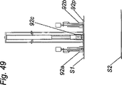
いくつかの実施形態において、ガイドプレートは、磁石又は他の一時的な取り付け機構、及び、レバーアーム84上のフレーム81及びロック装置を介してガイドプレートに伝達される油圧シリンダ上の力によって構造物に保持されることができるが、場合によっては、ロック装置は、省略されることができ、1つ以上の小孔パイプが、さらなるより大孔パイプが同様に加締められる前に、構造物に固定してそれを封止するようにガイドプレートに加締められることができる。したがって、単一のガイドプレートは、それに接続された複数のパイプを有することができる。図49は、そのような実施形態を示している。図49の実施形態において、ガイドプレートは、少なくとも3つのガイドチューブ92a、92b、92cを有し、ガイドチューブ92a、92bは、双方とも、小径(例えば2インチ)であり、ガイドチューブ92cは、大径チューブとすることができる。小径のガイドチューブは、図30の実施形態について記載されたようなものとすることができ、外側船殻S1にガイドプレートを取り付けるように使用されることができるとともに、ガイドプレートは、先に記載されたように、磁石(図示しない)を介して外側船殻S1に取り付けられる。2つの小さい穿孔チューブは、船殻に対してガイドプレートを封止することができ、船殻S1にガイドプレート用の固着機構を設けるとともに、それを介して漏出を防止することができる。一旦小径チューブがガイドプレートに取り付けられて船殻S1に加締められると、船殻S1間の空隙は、小孔パイプを介して別個に汲み出されることができる。場合により、小孔パイプの一方又は双方は、加熱して内容物を流動化させるために空隙にヒータを送るために使用されることができ、空隙が重油を含む場合に非常に有益であり得る。空隙が小孔パイプを介して空にされた後、より大きいガイドチューブ92cの大孔パイプは、第7の実施形態について記載されたものと同じ方法で内側船殻S2に加締められることができる。場合により、多くのそのようなユニットは、外側船殻S1に沿って様々な位置に取り付けられることができ、内側船殻S2内のタンクの油は、所定のパイプを介して挿入されたヒータによって加熱されることができ、1つ以上の異なるパイプを介して抽出される前に流動性を保持するように異なるパイプ間で循環される。
In some embodiments, the guide plate is structured by a magnet or other temporary attachment mechanism and a force on the hydraulic cylinder that is transmitted to the guide plate via the
変更例及び改良例は、本発明の範囲を逸脱しないで組み込まれることができる。例えば、第7の実施形態は、本明細書において記載されたように押し下げるよりもむしろ、頸部を介してドリフトを引き上げる駆動機構の変形例によって使用されることができる。いくつかの実施形態において、ロッドは、正方形の横断面を有することができ、他において横断面は円形とすることができる。ドリフトは、ドリルステムにおけるベアリング上に支持されることができ、通常、それが頸部を拡張させる場合には頸部に対して回転しない。遠心力に起因して半径方向に拡張し且つ静止時に半径方向に収縮する折り畳み可能なドリルビットが実施形態のいずれかと共に使用されることができ、したがって、そのようなビットは、パイプ内に収容されることができる静止時直径を有することができ、これにより、切削プロセス後にドリルビットをタンク内に落とすことを必要とせずに、パイプを介したドリルビットの配置及び回収を可能とする。 Modifications and improvements can be incorporated without departing from the scope of the invention. For example, the seventh embodiment can be used by a variation of the drive mechanism that raises the drift through the neck rather than pushing down as described herein. In some embodiments, the rod can have a square cross section and in others the cross section can be circular. The drift can be supported on bearings in the drill stem and normally does not rotate relative to the neck when it expands the neck. A collapsible drill bit that expands radially due to centrifugal force and contracts radially when stationary can be used with any of the embodiments, and such bit is therefore housed within the pipe Can have a quiescent diameter that can be done, which allows the drill bit to be placed and retrieved through the pipe without having to drop the drill bit into the tank after the cutting process.
Claims (20)
頸部を有する内部流路を有する導管であって、該導管の一部が前記構造物の孔内に収容されるように構成された、導管と、
前記導管の前記内部流路内に収容されるように構成され且つ少なくとも一部分が前記内部流路の前記頸部よりも大きな寸法を有する拡張装置と、
前記導管の前記内部流路を介して前記拡張装置を駆動して前記導管の前記頸部を拡げるように構成された駆動機構と、
を有し、
前記装置が、ドリルステムを備える孔開け機構を有し、
前記拡張装置が、前記拡張装置を介した前記ドリルステムの通過を可能とするアパーチャを備えており、
前記孔開け機構が、前記構造物に孔を形成するように構成された切削ビットを有し、
該切削ビットがドリルステムの端部に搭載されている、装置。An apparatus for transferring fluid to or from a structure,
A conduit having an internal flow path having a neck , the conduit configured to be received within a hole in the structure ;
An expansion device configured to be received within the internal flow path of the conduit and having at least a portion having a size larger than the neck of the internal flow path;
A drive mechanism configured to drive the expansion device through the internal flow path of the conduit to expand the neck of the conduit;
I have a,
The device has a drilling mechanism with a drill stem;
The expansion device comprises an aperture that allows the drill stem to pass through the expansion device;
The perforating mechanism has a cutting bit configured to form a hole in the structure;
An apparatus in which the cutting bit is mounted on the end of a drill stem .
前記油圧シリンダ及びピストン構成が、前記導管を駆動して前記構造物に接触させるとともに、前記拡張装置の移動を引き起こして前記頸部を通す、請求項1〜5のいずれか一項に記載の装置。The piercing mechanism, comprising a drill advancing the switching-cutting bits by the bit driving mechanism comprising a hydraulic cylinder and piston arrangement in the axial direction,
6. The device according to any one of claims 1-5 , wherein the hydraulic cylinder and piston arrangement drives the conduit to contact the structure and causes the expansion device to move through the neck. .
内部流路を有する導管に頸部を設けるステップと、
前記構造物の表面を通る孔を形成して、前記孔を介して前記導管の一部を通過可能とするステップと、
前記導管の一部を前記構造物における前記孔に通過させることによって前記導管の前記頸部を前記構造物における前記孔に通過させるステップと、
前記頸部において制限された嵌合をなすように構成された拡張装置を設けるステップと、
前記導管の頸部を通過する前記拡張装置を駆動するように構成された駆動装置を設けるステップと、
前記駆動装置を作動して前記導管の一部を介して前記拡張装置を駆動することによって前記拡張装置が前記頸部の領域における前記導管の前記内部流路の一部を広げるステップと、
ドリルステムと前記ドリルステムの端部に搭載された切削ビットとを備える孔開け機構を設けるステップとを備え、
前記孔が前記切削ビットが前記構造物を通って駆動されることにより切削され、前記拡張装置には前記ドリルステムを収容するアパーチャが設けられ、前記方法が前記拡張装置の前記アパーチャを介して前記ドリルステムを通過させることにより前記ドリルステムに前記拡張装置を搭載するステップを含む、方法。A method of attaching a conduit to a structure, comprising:
Providing a neck in a conduit having an internal flow path;
Forming a hole through the surface of the structure and allowing a portion of the conduit to pass through the hole;
Passing the neck of the conduit through the hole in the structure by passing a portion of the conduit through the hole in the structure;
Providing an expansion device configured to provide a limited fit at the neck;
Providing a drive configured to drive the dilator passing through the neck of the conduit;
A step of the expansion device by operating the drive device to drive the expansion device through a portion of the conduit extending the portion of the internal passage of the conduit in the region of the neck,
Providing a drilling mechanism comprising a drill stem and a cutting bit mounted on an end of the drill stem,
The hole is cut when the cutting bit is driven through the structure, the expansion device is provided with an aperture for receiving the drill stem, and the method is arranged through the aperture of the expansion device. Mounting the expansion device on the drill stem by passing a drill stem .
Applications Claiming Priority (3)
| Application Number | Priority Date | Filing Date | Title |
|---|---|---|---|
| GBGB0701600.9A GB0701600D0 (en) | 2007-01-27 | 2007-01-27 | Apparatus and method |
| GB0701600.9 | 2007-01-27 | ||
| PCT/GB2008/000273 WO2008090363A2 (en) | 2007-01-27 | 2008-01-28 | Method and apparatus for securing a conduit to a structure |
Publications (3)
| Publication Number | Publication Date |
|---|---|
| JP2010516971A JP2010516971A (en) | 2010-05-20 |
| JP2010516971A5 JP2010516971A5 (en) | 2011-03-10 |
| JP5087778B2 true JP5087778B2 (en) | 2012-12-05 |
Family
ID=37872909
Family Applications (1)
| Application Number | Title | Priority Date | Filing Date |
|---|---|---|---|
| JP2009546813A Expired - Fee Related JP5087778B2 (en) | 2007-01-27 | 2008-01-28 | Method and apparatus for securing a conduit to a structure |
Country Status (10)
| Country | Link |
|---|---|
| US (1) | US8528186B2 (en) |
| EP (1) | EP2106514B1 (en) |
| JP (1) | JP5087778B2 (en) |
| AT (1) | ATE520920T1 (en) |
| AU (1) | AU2008208681B2 (en) |
| BR (1) | BRPI0808003A2 (en) |
| ES (1) | ES2371979T3 (en) |
| GB (1) | GB0701600D0 (en) |
| NZ (1) | NZ578622A (en) |
| WO (1) | WO2008090363A2 (en) |
Families Citing this family (9)
| Publication number | Priority date | Publication date | Assignee | Title |
|---|---|---|---|---|
| CN101466591B (en) * | 2006-06-16 | 2013-03-20 | Itrec有限责任公司 | Heaving movement compensation |
| FR2975072B1 (en) * | 2011-05-13 | 2014-08-08 | Jlmd Ecologic Group | METHOD FOR DISCHARGING LIQUID FROM A TANK OF A DISASTER VESSEL |
| FI124420B (en) * | 2013-05-20 | 2014-08-29 | Alfons Håkans Oy Ab | Apparatus and method for recovering liquid from an underwater container |
| GB201415031D0 (en) * | 2014-08-25 | 2014-10-08 | Cansco Subsea Ltd | Method and apparatus for access and remediation of hydrocarbon storage tanks |
| JP6471515B2 (en) * | 2015-01-28 | 2019-02-20 | 日新電機株式会社 | Pipe holding connection structure and high-frequency antenna device including the same |
| WO2019182958A1 (en) * | 2018-03-19 | 2019-09-26 | Resolve Marine Group, Inc. | Marine salvage drill assemblies and systems |
| CN108687671B (en) * | 2018-04-20 | 2020-09-01 | 合肥通用机械研究院有限公司 | Cutting device for deep sea forcible entry |
| KR102202282B1 (en) * | 2019-10-11 | 2021-01-13 | 주식회사 지오이 | Apparatus for the removal of oil from sunken wrecks |
| CN114750901B (en) * | 2022-04-26 | 2023-04-11 | 烟台杰瑞石油装备技术有限公司 | Hole opening device, hole opening system, sunken ship oil pumping equipment and sunken ship oil pumping method |
Family Cites Families (20)
| Publication number | Priority date | Publication date | Assignee | Title |
|---|---|---|---|---|
| US998352A (en) * | 1910-12-16 | 1911-07-18 | Frederick W Kublin | Bung spout or funnel. |
| US2146461A (en) * | 1937-01-06 | 1939-02-07 | Aviat Developments Ltd | Method of riveting |
| US2410476A (en) * | 1943-10-08 | 1946-11-05 | Appleton Electric Co | Spinning tool |
| US3380420A (en) * | 1966-02-08 | 1968-04-30 | George T. Frederick Divine | Salvaging apparatus |
| US3822660A (en) * | 1973-01-08 | 1974-07-09 | Fmc Corp | Method and apparatus for salvaging a sunken vessel |
| GB1484259A (en) * | 1973-12-08 | 1977-09-01 | Tucker Fasteners Ltd | Blind-riveting tools for self-drilling rivets |
| SE403056B (en) * | 1976-11-10 | 1978-07-31 | Ventive Ab | KIT FOR BLIND RIVING AND DRILL FOR EXERCISING THE KIT |
| US4284110A (en) * | 1977-06-15 | 1981-08-18 | Frances K. Divelbiss | Apparatus for transfer of fluent materials from one container to another |
| JPS62123295A (en) * | 1985-11-21 | 1987-06-04 | Asahi Glass Co Ltd | Composite connection structure for tube and header |
| US4821665A (en) * | 1986-03-13 | 1989-04-18 | Honeywell Inc. | Submersible ROV for cleaning and inspecting metal |
| GB8809796D0 (en) * | 1988-04-26 | 1988-06-02 | Alh Syst Ltd | Pipe fitting |
| JPH02186183A (en) * | 1989-01-10 | 1990-07-20 | Shimizu Shigeo | Branched pipe burying method |
| JPH02212689A (en) * | 1989-02-10 | 1990-08-23 | Koken Shisui Kogyo Kk | Method of mounting branch pipe to embedded pipe and boring device for same method |
| GB9324560D0 (en) * | 1993-11-30 | 1994-01-19 | Framo Dev Uk Ltd | An apparatus for extraction of a fluent material from a container |
| US5795103A (en) * | 1996-02-26 | 1998-08-18 | Gaerlan; Doroteo C. | Oil tanker and method for recovering oil from submerged oil tanker |
| JP2004245317A (en) * | 2003-02-13 | 2004-09-02 | Jfe Engineering Kk | Composite piping having organic solvent penetration preventing structure, and method for preventing penetration of organic solvent |
| KR100442973B1 (en) * | 2004-02-25 | 2004-08-05 | 한국해양연구원 | Remotely operated recovery apparatus and recovery method for removing liquid contained in a sunken ship |
| ATE490166T1 (en) * | 2004-02-26 | 2010-12-15 | Saipem Sa | DEVICE AND METHOD FOR FASTENING A BASE STRUCTURE TO A WALL SURFACE ON THE SEABOTTOM |
| JP4101223B2 (en) * | 2004-10-12 | 2008-06-18 | 株式会社水道技術開発機構 | Bush mounting machine and branch pipe flow shielding device |
| JP4648760B2 (en) * | 2005-05-23 | 2011-03-09 | 株式会社水道技術開発機構 | Branch pipe renewal method |
-
2007
- 2007-01-27 GB GBGB0701600.9A patent/GB0701600D0/en not_active Ceased
-
2008
- 2008-01-28 AU AU2008208681A patent/AU2008208681B2/en not_active Ceased
- 2008-01-28 WO PCT/GB2008/000273 patent/WO2008090363A2/en active Application Filing
- 2008-01-28 BR BRPI0808003-8A2A patent/BRPI0808003A2/en not_active Application Discontinuation
- 2008-01-28 ES ES08701946T patent/ES2371979T3/en active Active
- 2008-01-28 NZ NZ578622A patent/NZ578622A/en not_active IP Right Cessation
- 2008-01-28 AT AT08701946T patent/ATE520920T1/en not_active IP Right Cessation
- 2008-01-28 JP JP2009546813A patent/JP5087778B2/en not_active Expired - Fee Related
- 2008-01-28 EP EP08701946A patent/EP2106514B1/en not_active Not-in-force
- 2008-01-28 US US12/448,928 patent/US8528186B2/en not_active Expired - Fee Related
Also Published As
| Publication number | Publication date |
|---|---|
| US20100032939A1 (en) | 2010-02-11 |
| NZ578622A (en) | 2012-01-12 |
| EP2106514A2 (en) | 2009-10-07 |
| BRPI0808003A2 (en) | 2014-06-17 |
| WO2008090363A2 (en) | 2008-07-31 |
| AU2008208681A1 (en) | 2008-07-31 |
| ES2371979T3 (en) | 2012-01-12 |
| AU2008208681B2 (en) | 2013-10-10 |
| EP2106514B1 (en) | 2011-08-17 |
| WO2008090363A3 (en) | 2008-10-09 |
| GB0701600D0 (en) | 2007-03-07 |
| US8528186B2 (en) | 2013-09-10 |
| JP2010516971A (en) | 2010-05-20 |
| ATE520920T1 (en) | 2011-09-15 |
Similar Documents
| Publication | Publication Date | Title |
|---|---|---|
| JP5087778B2 (en) | Method and apparatus for securing a conduit to a structure | |
| DE69916397T2 (en) | Method and device for actuating a downhole tool | |
| CN109653696B (en) | Natural gas hydrate rotary pressure-maintaining coring device | |
| NO330750B1 (en) | Well tool and method for cutting and extracting a rudder portion from a rudder string in a well | |
| US11364982B2 (en) | Marine salvage drill assemblies and systems | |
| NO20170992A1 (en) | Smooth-line operated and hydraulic-motor-driven pipe cutter | |
| US4750571A (en) | Screen placement method and apparatus | |
| FR2544011A1 (en) | POSITIONING TOOL ADAPTATION KIT, IN PARTICULAR FOR A WELL SEALING DEVICE | |
| US20100126777A1 (en) | Drilling System with a Barrel Drilling Head Driven by a Downhole Tractor | |
| US6230820B1 (en) | Universal drive point device | |
| JP5764476B2 (en) | Work tool introduction method | |
| NO327375B1 (en) | Method of inserting and extracting a hollow device in a flow tube | |
| EP2288471B1 (en) | Method of creating an underwater cutting zone, and related plugging devices and methods | |
| MXPA01011252A (en) | Spin pull module for threaded inserts. | |
| JP2007320019A (en) | Pipe drilling machine and pipe drilling method | |
| EP3186472B1 (en) | Method and apparatus for access and remediation of hydrocarbon storage tanks | |
| JP2006194346A (en) | Exchanging method of saddle ferrule, and assembly of saddle ferrule and saddle ferrule exchanger | |
| JP2776800B2 (en) | Perforator for pipe wall | |
| JPH082223Y2 (en) | Perforator coupling | |
| JP2023133845A (en) | Rock bolt construction method | |
| JPH075354Y2 (en) | Mounting device for perforating a branch communication port of a fluid pipe | |
| GB2546090A (en) | A subsea, stand-by installation | |
| JP2001182887A (en) | Gate valve mounting method for fluid transportation pipe and gate valve mounting device used for the same | |
| NO325774B1 (en) | Mounting device adapted for remote controlled mounting and disassembly, as well as methods for mounting and disassembling the mounting device |
Legal Events
| Date | Code | Title | Description |
|---|---|---|---|
| A521 | Request for written amendment filed |
Free format text: JAPANESE INTERMEDIATE CODE: A523 Effective date: 20110119 |
|
| A621 | Written request for application examination |
Free format text: JAPANESE INTERMEDIATE CODE: A621 Effective date: 20110119 |
|
| A977 | Report on retrieval |
Free format text: JAPANESE INTERMEDIATE CODE: A971007 Effective date: 20120720 |
|
| TRDD | Decision of grant or rejection written | ||
| A01 | Written decision to grant a patent or to grant a registration (utility model) |
Free format text: JAPANESE INTERMEDIATE CODE: A01 Effective date: 20120814 |
|
| A01 | Written decision to grant a patent or to grant a registration (utility model) |
Free format text: JAPANESE INTERMEDIATE CODE: A01 |
|
| A61 | First payment of annual fees (during grant procedure) |
Free format text: JAPANESE INTERMEDIATE CODE: A61 Effective date: 20120816 |
|
| FPAY | Renewal fee payment (event date is renewal date of database) |
Free format text: PAYMENT UNTIL: 20150921 Year of fee payment: 3 |
|
| R150 | Certificate of patent or registration of utility model |
Free format text: JAPANESE INTERMEDIATE CODE: R150 |
|
| R250 | Receipt of annual fees |
Free format text: JAPANESE INTERMEDIATE CODE: R250 |
|
| R250 | Receipt of annual fees |
Free format text: JAPANESE INTERMEDIATE CODE: R250 |
|
| R250 | Receipt of annual fees |
Free format text: JAPANESE INTERMEDIATE CODE: R250 |
|
| LAPS | Cancellation because of no payment of annual fees |