JP5083177B2 - Protector - Google Patents
Protector Download PDFInfo
- Publication number
- JP5083177B2 JP5083177B2 JP2008284993A JP2008284993A JP5083177B2 JP 5083177 B2 JP5083177 B2 JP 5083177B2 JP 2008284993 A JP2008284993 A JP 2008284993A JP 2008284993 A JP2008284993 A JP 2008284993A JP 5083177 B2 JP5083177 B2 JP 5083177B2
- Authority
- JP
- Japan
- Prior art keywords
- cassette block
- cassette
- door
- protector
- wire harness
- Prior art date
- Legal status (The legal status is an assumption and is not a legal conclusion. Google has not performed a legal analysis and makes no representation as to the accuracy of the status listed.)
- Expired - Fee Related
Links
Images


Description
本発明は自動車に配索されるワイヤハーネス外装用のプロテクタであって、特に、ワイヤハーネスの配索方向が相違する場合に共用で使用できるようにしているものである。 The present invention is a protector for the exterior of a wire harness that is routed in an automobile, and in particular, can be used in common when the direction of wiring harness is different.
自動車に配索されるワイヤハーネスは、経路規制や外部干渉材から電線群を保護する目的で、樹脂成形品からなるプロテクタに挿通されている。
該プロテクタは、底壁と両側壁とで囲まれた電線群の通路を設けた略樋形状とされ、長さ方向の両端の底壁からテープ巻き舌片を突出し、該テープ巻き舌片と電線群とに粘着テープを巻き付けて電線群をプロテクタに固定している。
The wire harness routed in the automobile is inserted into a protector made of a resin molded product for the purpose of protecting the electric wire group from the path regulation and the external interference material.
The protector has a substantially bowl shape provided with a passage of an electric wire group surrounded by a bottom wall and both side walls, projects a tape-wrapped tongue piece from the bottom walls at both ends in the length direction, and the tape-wrapped tongue piece and the wire Adhesive tape is wrapped around the group to secure the wire group to the protector.
自動車のドアへと配索されるワイヤハーネスは、通常、運転席の前方下部に収容されるジャンクションボックスから引き出され、その後、プロテクタを通してドア側へと配索されている。
自動車には、2ドア、3ドア、4ドアのタイプがあり、これらのドアへ配索されるワイヤハーネスは配索方向が相違するため、ドアのタイプ毎にドア用ワイヤハーネスのプロテクタを設ける必要がある。しかしながら、ドアのタイプ毎にプロテクタを形成すると、コスト高になる問題がある。
The wire harness routed to the door of the automobile is usually pulled out from a junction box housed in the lower front part of the driver's seat, and then routed to the door side through a protector.
There are two-door, three-door, and four-door types of automobiles, and the wiring harnesses routed to these doors have different wiring directions, so it is necessary to provide a door wire harness protector for each door type. There is. However, if a protector is formed for each door type, there is a problem that the cost increases.
一方、実開平4−101217号において、2組のワイヤハーネスをガイドできるプロテクタが提供されている。該プロテクタ100は図7(A)に示すように、支持板部100の両側に可撓部100a、100bを介して、スリット101a、102aを設けた可動板部101、102を備えている。図7(B)に示すように、可動板部101、102をスリット101a、102aで分離して折り曲げる方向を反対側とすることで、2組のワイヤハーネスWをガイド可能としている。
しかしながら、該プロテクタ100では2組のワイヤハーネスWの挿通方向の規制をできるが、3ドアでは3つのワイヤハーネス、4ドアでは4つのワイヤハーネスの方向規制をする必要がある。
On the other hand, in Japanese Utility Model Laid-Open No. 4-101217, a protector capable of guiding two sets of wire harnesses is provided. As shown in FIG. 7A, the
However, although the
このように、2ドア、3ドア、4ドアのワイヤハーネスに対して共用で用いることができるプロテクタが従来提供されていないため、図8に示すように、2ドア用の1つのプロテクタ200を共用し、3ドア、4ドアではワイヤハーネスを取り回して配索している。
即ち、2ドアの場合は、図8(A)(B)に示すように、底壁201の中央部に仕切壁202で第一通路203と第二通路204を設け、第一通路203に右側ドアのワイヤハーネスW1、第二通路204に左側ドアのワイヤハーネスW2を通し、出口203a、204aから引き出されたワイヤハーネスW1、W2を左右に分岐させた左右のドアへと配索している。
3ドアの場合は、図8(C)に示すように、プロテクタ200内の第一通路203に右ドアへ配索するワイヤハーネスW1と後部ドアへ配索するワイヤハーネスW3を通し、後部ドアへのワイヤハーネスW3は出口203aから引き出した後にプロテクタ200の外面に沿って折り返して後部ドアへと配索している。
4ドアの場合は、図8(D)に示すように、プロテクタ200内の第一通路203、204に前後の左右のワイヤハーネスW1とW4、W2とW5を通した後に、W4とW5とを出口203a、204aから引き出した後に、折り返した後に自動車に後部側へと配索している。該折り返し位置でクランプあるいはプロテクタ(図示せず)で経路規制した後に、自動車に後部側へと配索している。
Thus, since there has not been conventionally provided a protector that can be used in common for a 2-door, 3-door, and 4-door wire harness, as shown in FIG. 8, one
That is, in the case of two doors, as shown in FIGS. 8A and 8B, a
In the case of three doors, as shown in FIG. 8C, the wire harness W1 routed to the right door and the wire harness W3 routed to the rear door are passed through the
In the case of four doors, as shown in FIG. 8D, after passing the left and right wire harnesses W1 and W4 and W2 and W5 through the
このように、2ドア用プロテクタ200に3ドア、4ドアのワイヤハーネスを共用して用いると、3ドアの後部ドア用ワイヤハーネスW3、4ドアの後部左右ドア用ワイヤハーネスW4、W5の取り回し部分Zが必要となり、かつ、折り返し位置等で車体側にクランプ止めする必要がある等、多くの無駄が発生する。しかも、外部部材と干渉する恐れもある。
Thus, when the 3-door and 4-door wire harnesses are used in common for the 2-
前記のようにドアのタイプが相違する場合に限らず、車種の相違により、配索されるワイヤハーネスの分岐方向が相違する場合にも、ワイヤハーネス毎にプロテクタを設けるとコストが増加し、プロテクタを共用してワイヤハーネスを取り回して用いるとワイヤハーネスに無駄が発生すると共に他の部品が必要となる等の問題がある。
本発明は、前記した問題を解消せんとするもので、例えば、ドアのタイプが2ドア、3ドア、4ドアと相違する異なる車種において、ワイヤハーネスに無駄な取り回しを発生させずに対応できるプロテクタを提供することを課題としている。 The present invention is intended to solve the above-described problems. For example, a protector that can handle a wire harness in a different vehicle type that is different from a two-door, a three-door, and a four-door without causing unnecessary wiring in the wire harness. It is an issue to provide.
前記課題を解決するため、本発明は、車種が異なる自動車に配索されるワイヤハーネスの配索方向に対応させて用いられる複数のカセットブロックを備え、
前記各カセットブロックは、底壁と、該底壁の幅方向の両端縁から突出する側壁とで電線通路を備え、各カセットブロックは長さ方向の両端に電線挿通用開口を備えるとともに、前記側壁の少なくとも一方の中間位置に中間出口を備えた形状とし、
前記各カセットブロックは前記側壁外面に互いに係止できるロック部を備えると共に、前記底壁の長さ方向の先端に互いにロック部を備えていることを特徴とするプロテクタを提供している。
In order to solve the above-mentioned problem, the present invention comprises a plurality of cassette blocks used corresponding to the wiring direction of a wire harness that is routed to an automobile of a different vehicle type,
Each cassette block includes an electric wire passage with a bottom wall and side walls protruding from both end edges in the width direction of the bottom wall, and each cassette block includes an electric wire insertion opening at both ends in the length direction, and the side wall A shape having an intermediate outlet at at least one intermediate position of
Each of the cassette blocks includes a lock portion that can be locked to the outer surface of the side wall, and a lock portion that is provided with a lock portion at the front end in the length direction of the bottom wall.
前記のように、プロテクタを構成するカセットブロックを複数種用意しておくと、車種が相違してワイヤハーネスの配索方向が異なっても、カセットブロックを選択して着脱自在に組み合わせて形成することができる。このように、複数種類のカセットブロックを用意し、かつ、任意のカセットブロックを組み合わせても互いに連結できる構成としておくことで、異なる車種に対して共用で用いられるプロテクタを簡単に設けることができる。 As mentioned above, if you prepare multiple types of cassette blocks that make up the protector, even if the vehicle type is different and the wiring direction of the wire harness is different, the cassette blocks can be selected and detachably combined Can do. In this way, by preparing a plurality of types of cassette blocks and making them connectable to each other even if arbitrary cassette blocks are combined, a protector used in common for different vehicle types can be easily provided.
具体的には、前記カセットブロックとして、形状を相違させた第1、第2、第3、…第Nカセットブロックを備え、第1カセットブロックを基本カセットブロックとすると、該第1カセットブロックの側壁の中間部に前記中間出口を備え、該側壁の前記中間出口を挟む外面にそれぞれ前記ロック部の係止枠部を設けると共に前記底壁の長さ方向の一端にロック部のロック枠、他端にロック爪を備え、
前記第2、第3、…第Nカセットブロックは第1カセットブロックの幅方向に並設させて前記中間出口同士を連通させるカセットブロックとし、または、第1カセットブロックの長さ方向の一端に連続させるカセットブロックとしている。
Specifically, the cassette block includes first, second, third,..., Nth cassette blocks having different shapes, and when the first cassette block is a basic cassette block, the side wall of the first cassette block. The intermediate outlet is provided with the intermediate outlet, the locking frame of the lock part is provided on the outer surface of the side wall sandwiching the intermediate outlet, and the lock frame of the lock part is provided at one end in the length direction of the bottom wall. With a locking claw
The second, third,..., N-th cassette blocks are arranged in parallel in the width direction of the first cassette block so that the intermediate outlets communicate with each other, or continuous with one end in the length direction of the first cassette block. The cassette block to be used.
さらに、前記第1カセットブロック以外のカセットブロックとして、長さ方向に円弧部を備え、該円弧部を通してワイヤハーネスを方向変換して引き出すものを備えている。 Furthermore, as a cassette block other than the first cassette block, an arc portion is provided in the length direction, and the wire harness is changed in direction and pulled out through the arc portion.
さらに、前記第1カセットブロック以外のカセットブロックとして、長さ方向の中間部に段差部を備え、該段差部を通してワイヤハーネスの配索高さを変えて引き出すものとしている。 Further, as a cassette block other than the first cassette block, a step portion is provided at an intermediate portion in the length direction, and the wiring harness is arranged at a different height to be pulled out through the step portion.
前記複数種類のカセットブロックを組み合わせ、または、単独で用いることで、4ドア、3ドアおよび2ドアの自動車に配索するドア用ワイヤハーネスに共用で用いられることができるプロテクタとすることができる。
また、ドアのタイプが異なる場合にかぎらず、車種によって、分岐させて用いるワイヤハーネスの分岐方向が相違する場合にも好適に用いることができる。
By combining or independently using the plurality of types of cassette blocks, it is possible to provide a protector that can be used in common for a wire harness for a door routed in a 4-door, 3-door, and 2-door automobile.
Moreover, not only when the type of door is different, but also when the branch direction of the wire harness to be branched differs depending on the vehicle type, it can be suitably used.
前記のように、複数種類のカセットブロックを予め用意しておくと、車種の異なることにより、ワイヤハーネスの配索方向が相違する場合に、カセットブロックの組み合わせにより、最適な配索方向を有するプロテクタを簡単に形成することができる。
その結果、プロテクタを車種毎にワイヤハーネスの配索方向に応じて成形する必要はなく、大幅なコスト低下を図ることができる。また、プロテクタから引き出されるワイヤハーネスの配索方向への取り回しを不要とでき、ワイヤハーネスの無駄およびワイヤハーネスの付属部品の無駄を無くし、かつ、取り回しにより発生する恐れがあるワイヤハーネスの損傷の発生を防止できる。
As described above, when a plurality of types of cassette blocks are prepared in advance, when the wiring direction of the wire harness is different due to different vehicle types, the protector having the optimal wiring direction can be obtained by combining the cassette blocks. Can be easily formed.
As a result, it is not necessary to form the protector according to the wiring direction of the wire harness for each vehicle type, and a significant cost reduction can be achieved. In addition, it is not necessary to route the wiring harness that is pulled out from the protector in the wiring direction, and it is possible to eliminate the waste of the wiring harness and the accessories of the wiring harness, and the occurrence of damage to the wiring harness that may occur due to the handling. Can be prevented.
以下、本発明のプロテクタの実施形態を図面を参照して説明する。
図1乃至図6に実施形態のプロテクタを示す。
Hereinafter, embodiments of a protector of the present invention will be described with reference to the drawings.
The protector of embodiment is shown in FIG. 1 thru | or FIG.
プロテクタを構成する第一カセットブロック10、第二カセットブロック20、第三カセットブロック30、第四カセットブロック40を予め設けている。
A
前記第一〜第四カセットブロック10〜40は、いずれも樹脂成形品からなり、図2(A)に示す第一カセットブロック10、図2(B)に示す第四カセットブロック40と同様に、底壁1、該底壁1の幅方向の両端縁から突出する側壁2、3とで電線通路5を形成しており、長さ方向Lが長い樋形状としている。
Each of the first to
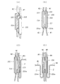
図1(A)および図2(A)に示す第一カセットブロック10は、両側壁2、3の中間部に中間出口11、12を備え、長さ方向の一端側の入口13から挿入するワイヤハーネスWを他端側の出口14から引き出せると共に、前記中間出口11、12の両方または一方から引き出せるようにしている。
前記中間出口11を挟む側壁2の外面にはそれぞれロック部を構成するロック枠部15Aと15Bを突設する一方、他方が側壁3の外面にはそれぞれロック部を構成するロック爪16Aと16Bを突設している。また、底壁1の長さ方向の一端にロック枠部17A、他端にロック爪17Bを設けている。
さらに、底壁1の長さ方向の両側の入口13側と出口14側には中間仕切壁18、19を突設し、該中間仕切壁18、19に挟まれた仕切壁の無い部分に前記中間出口11、12を設け、右通路5A、左通路5Bとに分けている。
A
Further,
図1(B)に示す第二カセットブロック20は、第一カセットブロック10の略2倍の長さを有し、一方の側壁3には中間出口を設けていない一方、他方の側壁2には2個の中間出口21、22を設けている。該中間出口21、22を挟む側壁2の外面に3個のロック枠部23A、23B、23Cを設けている。該ロック枠部23A、23Bを第一カセットブロック10のロック爪16A、16Bとロック係止すると、第一カセットブロック10の中間出口11と第二カセットブロック20の中間出口21とが連通した状態で、第一、第二カセットブロック10、20とが結合される。
また、第二カセットブロック20のロック枠部23B、23Cを、第一カセットブロック10のロック爪16A、16Bとロック係止すると、第一カセットブロック10の中間出口12と第二カセットブロック20の中間出口22とが連通した状態で、第一、第二カセットブロック10、20とが結合される。
該第二カセットブロック20にも、入口25側の底壁先端にロック爪27B、出口26にロック枠部27Aを設け、入口25、出口26の底壁には中間仕切壁28A、28Bを突設している。
The
Further, when the
The
図1(C)に示す第三カセットブロック30は、長さ方向の後部側は直線部31とし前部側は円弧部32として連続させた形状としている。直線部31と円弧部32との間の両側壁2、3に中間出口33、34を設けている。また、直線部31の側壁3の外面にロック爪35を設け、対向する側壁2にロック枠部36を設けている。該第三カセットブロック30にも、長さ方向の両端にロック枠部37Aとロック爪37Bを設けている。
前記ロック爪35を第一カセットブロック10のロック枠部15Bとロック結合すると、中間出口11と33とが連通した状態で、第一、第三カセットブロック10、30とが結合される。
The
When the
図1(D)および図2(B)に示す第四カセットブロック40は、第一カセットブロック10の3倍以上の長さを有し、その長さ方向の中央部に上下段差部41を設け、段差部41の一方側を低位部42、他方側を高位部43としている。側壁3には中間出口を設けず、側壁2には低位部42に中間出口44、高位部43に中間出口45を設けている。中間出口44を挟む側壁2の外面にロック枠部46Aと46Bを設け、中間出口45を挟む側壁2の外面にロック枠部47Aと47Bを突設している。該第四カセットブロック40にも、長さ方向の両端にロック枠部48Aとロック爪48Bを設けている。
The
前記第四カセットブロック40のロック枠部46Aと46Bとを第一カセットブロック10のロック爪16A、16Bとロック結合し、または、ロック枠部47Aと47Bとを第一カセットブロック10のロック爪16A、16Bとロック結合できるようにし、第四カセットブロック40から引き出されるワイヤハーネスを上位置または下位置へと配索できるようにしている。
The
前記カセットブロックを用いて、2ドア、3ドア、4ドアに配索されるワイヤハーネスのプロテクタを形成する場合について説明する。 The case where the protector of the wire harness routed by 2 doors, 3 doors, and 4 doors is formed using the cassette block will be described.
2ドア用のプロテクタと4ドア用のプロテクタP−1は第一カセットブロック10で共用している。
即ち、図3(A)に示すように、2ドアの場合は右ドアへと配索するワイヤハーネスW1を右通路5Aに、左ドアへ配索するワイヤハーネスW2は左通路5Bに通し、入口13から通し、出口14でワイヤハーネスW1を右側へと引き出して配索し、ワイヤハーネスW2は左側へと引き出して配索している。
このように、中間仕切壁18、19でワイヤハーネスW1、W2を右通路5A、左通路5Bと振り分けて配索できるため、配索間違いが防止でき、配索作業性を高めることができる。
The two-door protector and the four-door protector P-1 are shared by the
That is, as shown in FIG. 3 (A), in the case of two doors, the wire harness W1 routed to the right door is passed through the
Thus, since the wiring harnesses W1 and W2 can be routed separately from the
図3(B)に示すように、4ドアの場合は、右側前後のドアへ配索するワイヤハーネスW1、W4を入口13から右通路5Aに挿入し、後右ドアへ配索するワイヤハーネスW4は中間出口11から引き出し、前右ドアへ配索するワイヤハーネスW1は出口14から引き出す。左側前後のドアへ配索するワイヤハーネスW2、W5を入口13から左通路5Bに挿入し、後左ドアへ配索するワイヤハーネスW5は中間出口12から引き出し、前左ドアへ配索するワイヤハーネスW2は出口14から引き出している。
この場合も中間仕切壁でワイヤハーネスの振り分けができるため、配索間違いが防止でき、配索作業性を高めることができる。
As shown in FIG. 3 (B), in the case of four doors, wire harnesses W1 and W4 routed to the right front and rear doors are inserted into the
Also in this case, since the wiring harness can be distributed by the intermediate partition wall, it is possible to prevent a wiring mistake and to improve the wiring workability.
3ドアの場合は、図4(A)に示すように、プロテクタP−2は第一カセットブロック10の左側に第二カセットブロック20をロック結合している。
この場合、左右ドアへ配索するワイヤハーネスW1、W2は第二カセットブロック20の右通路5Aと左通路5Bに通し、2ドアの場合と同様に左右のドアへと配索する。
バックドアへ配索するワイヤハーネスW3は第一カセットブロック10に通し、中間出出口11から引き出して後部側へと配索している。
In the case of three doors, as shown in FIG. 4A, the protector P-2 has the
In this case, the wire harnesses W1 and W2 routed to the left and right doors are routed through the
The wire harness W3 routed to the back door is passed through the
前記第二カセットブロック20を第一カセットブロック10に連結する代わりに、図4(B)に示すように、第一カセットブロック10のみを用い、右通路5AにワイヤハーネスW1とW3を通し、バックドア側へ配索するワイヤハーネスW3を中間出口11から引き出し、右ドアへ配索するワイヤハーネスW1を出口14から引き出しても良い。
Instead of connecting the
さらに、図4(C)に示すように、第一カセットブロック10に第三カセットブロック30を連結し、バックドアへ配索するワイヤハーネスW3を第一カセットブロックの中間出口11から第三カセットブロック30に通し、円弧部32を通して引き出してもよい。
Further, as shown in FIG. 4C, the
図4(A)(B)(C)のいずれのプロテクタとするかは、車両条件に応じて選択される。
また、ドアに配索するワイヤハーネスにかぎらず、他の機器に配索するワイヤハーネスにおいても、車両条件に応じて、図4(A)(B)(C)のいずれかを選択してプロテクタとして用いることができる。
Which of the protectors in FIGS. 4A, 4B and 4C is selected according to the vehicle conditions.
Further, in the case of a wire harness routed to another device, not only a wire harness routed to a door, any one of FIGS. 4A, 4B, and 4C can be selected according to vehicle conditions. Can be used as
さらに、自動車に配索するワイヤハーネス用のプロテクタP−3として、図5(A)(B)(C)に示すように、第一カセットブロック10と第四カセットブロック40との組み合わせで、ワイヤハーネスを高低差を持たせて引き出すことができる。
即ち、図5(A)に示すように、第四カセットブロック40の低位部のロック枠部46Aと46Bを第一カセットブロック10のロック爪16A、16Bとロック結合すると、第一カセットブロック10から第四カセットブロック40に挿通したワイヤハーネスW6とW7とは、ワイヤハーネスW6を中間出口44から第一カセットブロック10の中間出口12へと引き出し、該中間出口12から前後方向に分岐して配索できる。ワイヤハーネスW7は上下段差41を通して高位置の出口から引き出している。これにより、ワイヤハーネスW6とW7とに高低差を持たせて引き出すことができる。
Further, as a protector P-3 for a wire harness routed in an automobile, as shown in FIGS. 5 (A), (B), and (C), a combination of the
That is, as shown in FIG. 5A, when the lower
図5(B)に示すように、第四カセットブロック40の高位部のロック枠部47Aと47Bを第一カセットブロック10のロック爪16A、16Bとロック結合すると、第四カセットブロック40に挿通したワイヤハーネスW6とW7とは、ワイヤハーネスW6を中間出口45から第一カセットブロック10の中間出口12へと引き出し、高位置で分岐でき、ワイヤハーネスW6も高位置の出口から引き出せる。この場合、ワイヤハーネスW6とW7とは引き出し位置で高低差はないが、第四カセットブロック40の低位置の入口側に対して、高位置の出口側から分岐させて引き出すことができる。
As shown in FIG. 5 (B), when the
図5(C)に示すように、第一カセットブロック10を2個設け、第四カセットブロック40の低位置と高位置の両方に第一カセットブロック10をそれぞれ連結すると、第四カセットブロック40から2個の第一カセットブロック10にそれぞれ挿通させるワイヤハーネスW8、W9を高低差を設けて分岐して引き出すことができる。
As shown in FIG. 5C, when two first cassette blocks 10 are provided and the
さらに、プロテクタによるワイヤハーネスの保護ガイド領域を長くする必要がある場合のプロテクタP−3とする場合には、図6(A)(B)に示すように結合している。
図6(A)に示すように、第一カセットブロック10に第二カセットブロック20を長さ方向に連結している。即ち、第一カセットブロック10の底壁1の一端に設けたロック枠部17Aに第二カセットブロック20の底壁1に設けたロック爪27Bをロック結合している。
図6(B)では、第一カセットブロック10に第四カセットブロック40を互いの底壁に設けたロック枠部とロック爪とを係止してロック結合している。
Furthermore, when it is set as the protector P-3 when it is necessary to lengthen the protection guide area | region of the wire harness by a protector, it couple | bonds as shown to FIG. 6 (A) (B).
As shown in FIG. 6A, the
In FIG. 6 (B), the
このように、第一〜第四カセットブロック10〜40を用意しておくことにより、車種が相違し、ワイヤハーネスの分岐位置、配索高低位置が相違した場合など、種々の配索形態に適応したプロテクタとすることができる。
よって、車種毎にワイヤハーネスの配索形態に対応したプロテクタをそれぞれ個別に成形する必要はなく、プロテクタの金型製作費を大幅に減額でき、コストの低下を図ることができる。かつ、プロテクタから引き出した後にワイヤハーネスを取り回す必要がなくなるため、ワイヤハーネスの無駄を省くことができるとともに、取り回したワイヤハーネスを車体に係止するクランプ等の付属部品も不要とでき、部品コスト、取り付けコストの削減を図ることができる。
In this way, by preparing the first to fourth cassette blocks 10 to 40, the vehicle type is different, and the wiring harness branching position and the wiring height position are different. Protector.
Therefore, it is not necessary to individually form a protector corresponding to the wiring form of the wire harness for each vehicle type, and the mold production cost of the protector can be greatly reduced, and the cost can be reduced. In addition, since it is no longer necessary to route the wire harness after it is pulled out from the protector, it is possible to eliminate the waste of the wire harness and to eliminate the need for attached parts such as clamps for locking the routed wire harness to the vehicle body. The installation cost can be reduced.
本発明は前記実施形態に限定されず、用意しておくカセットブロックとして、前記第一〜第四カセットブロックと形状を相違させるとともに、幅方向および長さ方向にロック結合できるカセットブロックを用意しておいてもよい。しかしながら、予め用意するカセットブロックの種類が増加するとコスト高になる恐れがあるため、種類は少ない方が好ましい。 The present invention is not limited to the above embodiment, and as a cassette block to be prepared, a cassette block that has a shape different from that of the first to fourth cassette blocks and can be lock-coupled in the width direction and the length direction is prepared. It may be left. However, if the number of types of cassette blocks prepared in advance increases, the cost may increase, so it is preferable that the number of types is smaller.
1 底壁
2、3 側壁
5(5A、5B) 電線通路
10 第一カセットブロック
12、13 中間出口
15A、15B ロック枠部
16A、16B ロック爪
17A ロック枠部
17B ロック爪
20 第二カセットブロック
30 第三カセットブロック
40 第四カセットブロック
W1〜W9 ワイヤハーネス
P−1〜P−4 プロテクタ
1
Claims (5)
前記各カセットブロックは、底壁と、該底壁の幅方向の両端縁から突出する側壁とで電線通路を備え、各カセットブロックは長さ方向の両端に電線挿通用開口を備えるとともに、前記側壁の少なくとも一方の中間位置に中間出口を備えた形状とし、
前記各カセットブロックは前記側壁外面に互いに係止できるロック部を備えると共に、前記底壁の長さ方向の先端に互いにロック部を備えていることを特徴とするプロテクタ。 Provided with a plurality of cassette blocks used corresponding to the wiring direction of the wire harness that is routed to different types of vehicles,
Each cassette block includes an electric wire passage with a bottom wall and side walls protruding from both end edges in the width direction of the bottom wall, and each cassette block includes an electric wire insertion opening at both ends in the length direction, and the side wall A shape having an intermediate outlet at at least one intermediate position of
Each of the cassette blocks includes a lock portion that can be locked to the outer surface of the side wall, and includes a lock portion at the front end in the length direction of the bottom wall.
前記第2、第3、…第Nカセットブロックは第1カセットブロックの幅方向に並設させて前記中間出口同士を連通させるカセットブロックとし、または、第1カセットブロックの長さ方向の一端に連続させるカセットブロックとしている請求項1に記載のプロテクタ。 As the cassette block, there are provided first, second, third,... N cassette blocks having different shapes, and when the first cassette block is a basic cassette block, the cassette block is provided in the middle of the side wall of the first cassette block. An intermediate outlet is provided, a locking frame portion of the lock portion is provided on an outer surface of the side wall sandwiching the intermediate outlet, a lock frame of the lock portion is provided at one end in the length direction of the bottom wall, and a lock claw is provided at the other end. ,
The second, third,..., N-th cassette blocks are arranged in parallel in the width direction of the first cassette block so that the intermediate outlets communicate with each other, or continuous with one end in the length direction of the first cassette block. The protector according to claim 1, wherein the protector is a cassette block.
Priority Applications (1)
| Application Number | Priority Date | Filing Date | Title |
|---|---|---|---|
| JP2008284993A JP5083177B2 (en) | 2008-11-06 | 2008-11-06 | Protector |
Applications Claiming Priority (1)
| Application Number | Priority Date | Filing Date | Title |
|---|---|---|---|
| JP2008284993A JP5083177B2 (en) | 2008-11-06 | 2008-11-06 | Protector |
Publications (2)
| Publication Number | Publication Date |
|---|---|
| JP2010114995A JP2010114995A (en) | 2010-05-20 |
| JP5083177B2 true JP5083177B2 (en) | 2012-11-28 |
Family
ID=42303100
Family Applications (1)
| Application Number | Title | Priority Date | Filing Date |
|---|---|---|---|
| JP2008284993A Expired - Fee Related JP5083177B2 (en) | 2008-11-06 | 2008-11-06 | Protector |
Country Status (1)
| Country | Link |
|---|---|
| JP (1) | JP5083177B2 (en) |
Families Citing this family (4)
| Publication number | Priority date | Publication date | Assignee | Title |
|---|---|---|---|---|
| JP5244924B2 (en) | 2010-10-01 | 2013-07-24 | 日立ビークルエナジー株式会社 | Power storage device |
| CN102548263A (en) * | 2010-12-15 | 2012-07-04 | 鸿富锦精密工业(深圳)有限公司 | Casing of electronic device |
| JP5965797B2 (en) * | 2012-09-18 | 2016-08-10 | 矢崎総業株式会社 | Harness protector |
| JP5983524B2 (en) * | 2013-05-08 | 2016-08-31 | 住友電装株式会社 | Protector and connected protector |
Family Cites Families (2)
| Publication number | Priority date | Publication date | Assignee | Title |
|---|---|---|---|---|
| JPH10322840A (en) * | 1997-05-19 | 1998-12-04 | Sumitomo Wiring Syst Ltd | Protector |
| JP2003304622A (en) * | 2002-04-05 | 2003-10-24 | Yazaki Corp | Wiring structure of wire harness |
-
2008
- 2008-11-06 JP JP2008284993A patent/JP5083177B2/en not_active Expired - Fee Related
Also Published As
| Publication number | Publication date |
|---|---|
| JP2010114995A (en) | 2010-05-20 |
Similar Documents
| Publication | Publication Date | Title |
|---|---|---|
| JP5353654B2 (en) | Protector for wire harness | |
| JP5083177B2 (en) | Protector | |
| JP6020394B2 (en) | Exterior material for wire harness and wiring structure of wire harness | |
| US7507905B2 (en) | Electrical junction box | |
| CN109313965B (en) | Wire harness | |
| JP3293556B2 (en) | Protector | |
| CN103328267A (en) | Wire harness cable routing structure and protector | |
| DE4138714A1 (en) | WIRING KIT FOR THE VEHICLE ON-LINE NETWORK | |
| WO2017073381A1 (en) | Exterior material for wire harness | |
| JP5131087B2 (en) | Wire harness protector | |
| JP6691670B2 (en) | Wire harness protector and wire harness wiring structure using the same | |
| JP4600333B2 (en) | Electrical junction box | |
| JP2019161965A5 (en) | ||
| JP2012071700A (en) | Wiring structure of rear part of motorcycle | |
| JP5630307B2 (en) | Wire harness wiring structure | |
| JP4394205B2 (en) | Control cable joint structure | |
| JP2015101111A (en) | Protective structure of wire harness for horn of vehicle, and front grille module of vehicle | |
| JP5614363B2 (en) | Protector for wire harness | |
| JP3825349B2 (en) | Harness branch structure for in-car LAN of automobile | |
| JPH08205356A (en) | Structure of installing wiring harness | |
| JP4680740B2 (en) | Wiring harness wiring structure | |
| CN215663301U (en) | Pencil protects box and vehicle | |
| JP3139331B2 (en) | Wire harness | |
| JP6225936B2 (en) | Wire harness wiring device for slide sheet | |
| JP7388851B2 (en) | Protector and wire harness |
Legal Events
| Date | Code | Title | Description |
|---|---|---|---|
| A621 | Written request for application examination |
Free format text: JAPANESE INTERMEDIATE CODE: A621 Effective date: 20101209 |
|
| A977 | Report on retrieval |
Free format text: JAPANESE INTERMEDIATE CODE: A971007 Effective date: 20120229 |
|
| TRDD | Decision of grant or rejection written | ||
| A01 | Written decision to grant a patent or to grant a registration (utility model) |
Free format text: JAPANESE INTERMEDIATE CODE: A01 Effective date: 20120807 |
|
| A01 | Written decision to grant a patent or to grant a registration (utility model) |
Free format text: JAPANESE INTERMEDIATE CODE: A01 |
|
| A61 | First payment of annual fees (during grant procedure) |
Free format text: JAPANESE INTERMEDIATE CODE: A61 Effective date: 20120820 |
|
| R150 | Certificate of patent (=grant) or registration of utility model |
Free format text: JAPANESE INTERMEDIATE CODE: R150 |
|
| FPAY | Renewal fee payment (prs date is renewal date of database) |
Free format text: PAYMENT UNTIL: 20150914 Year of fee payment: 3 |
|
| LAPS | Cancellation because of no payment of annual fees |