JP5082053B2 - Manufacturing method of microneedle or microimplant - Google Patents
Manufacturing method of microneedle or microimplant Download PDFInfo
- Publication number
- JP5082053B2 JP5082053B2 JP2007526569A JP2007526569A JP5082053B2 JP 5082053 B2 JP5082053 B2 JP 5082053B2 JP 2007526569 A JP2007526569 A JP 2007526569A JP 2007526569 A JP2007526569 A JP 2007526569A JP 5082053 B2 JP5082053 B2 JP 5082053B2
- Authority
- JP
- Japan
- Prior art keywords
- solid
- needle
- droplet
- substance
- droplets
- Prior art date
- Legal status (The legal status is an assumption and is not a legal conclusion. Google has not performed a legal analysis and makes no representation as to the accuracy of the status listed.)
- Expired - Fee Related
Links
Images


Classifications
-
- B—PERFORMING OPERATIONS; TRANSPORTING
- B81—MICROSTRUCTURAL TECHNOLOGY
- B81C—PROCESSES OR APPARATUS SPECIALLY ADAPTED FOR THE MANUFACTURE OR TREATMENT OF MICROSTRUCTURAL DEVICES OR SYSTEMS
- B81C1/00—Manufacture or treatment of devices or systems in or on a substrate
- B81C1/00015—Manufacture or treatment of devices or systems in or on a substrate for manufacturing microsystems
- B81C1/00023—Manufacture or treatment of devices or systems in or on a substrate for manufacturing microsystems without movable or flexible elements
- B81C1/00111—Tips, pillars, i.e. raised structures
-
- A—HUMAN NECESSITIES
- A61—MEDICAL OR VETERINARY SCIENCE; HYGIENE
- A61M—DEVICES FOR INTRODUCING MEDIA INTO, OR ONTO, THE BODY; DEVICES FOR TRANSDUCING BODY MEDIA OR FOR TAKING MEDIA FROM THE BODY; DEVICES FOR PRODUCING OR ENDING SLEEP OR STUPOR
- A61M37/00—Other apparatus for introducing media into the body; Percutany, i.e. introducing medicines into the body by diffusion through the skin
- A61M37/0015—Other apparatus for introducing media into the body; Percutany, i.e. introducing medicines into the body by diffusion through the skin by using microneedles
-
- B—PERFORMING OPERATIONS; TRANSPORTING
- B29—WORKING OF PLASTICS; WORKING OF SUBSTANCES IN A PLASTIC STATE IN GENERAL
- B29C—SHAPING OR JOINING OF PLASTICS; SHAPING OF MATERIAL IN A PLASTIC STATE, NOT OTHERWISE PROVIDED FOR; AFTER-TREATMENT OF THE SHAPED PRODUCTS, e.g. REPAIRING
- B29C37/00—Component parts, details, accessories or auxiliary operations, not covered by group B29C33/00 or B29C35/00
- B29C37/0053—Moulding articles characterised by the shape of the surface, e.g. ribs, high polish
-
- B—PERFORMING OPERATIONS; TRANSPORTING
- B29—WORKING OF PLASTICS; WORKING OF SUBSTANCES IN A PLASTIC STATE IN GENERAL
- B29C—SHAPING OR JOINING OF PLASTICS; SHAPING OF MATERIAL IN A PLASTIC STATE, NOT OTHERWISE PROVIDED FOR; AFTER-TREATMENT OF THE SHAPED PRODUCTS, e.g. REPAIRING
- B29C64/00—Additive manufacturing, i.e. manufacturing of three-dimensional [3D] objects by additive deposition, additive agglomeration or additive layering, e.g. by 3D printing, stereolithography or selective laser sintering
- B29C64/10—Processes of additive manufacturing
- B29C64/106—Processes of additive manufacturing using only liquids or viscous materials, e.g. depositing a continuous bead of viscous material
- B29C64/124—Processes of additive manufacturing using only liquids or viscous materials, e.g. depositing a continuous bead of viscous material using layers of liquid which are selectively solidified
- B29C64/129—Processes of additive manufacturing using only liquids or viscous materials, e.g. depositing a continuous bead of viscous material using layers of liquid which are selectively solidified characterised by the energy source therefor, e.g. by global irradiation combined with a mask
- B29C64/135—Processes of additive manufacturing using only liquids or viscous materials, e.g. depositing a continuous bead of viscous material using layers of liquid which are selectively solidified characterised by the energy source therefor, e.g. by global irradiation combined with a mask the energy source being concentrated, e.g. scanning lasers or focused light sources
-
- A—HUMAN NECESSITIES
- A61—MEDICAL OR VETERINARY SCIENCE; HYGIENE
- A61M—DEVICES FOR INTRODUCING MEDIA INTO, OR ONTO, THE BODY; DEVICES FOR TRANSDUCING BODY MEDIA OR FOR TAKING MEDIA FROM THE BODY; DEVICES FOR PRODUCING OR ENDING SLEEP OR STUPOR
- A61M37/00—Other apparatus for introducing media into the body; Percutany, i.e. introducing medicines into the body by diffusion through the skin
- A61M37/0015—Other apparatus for introducing media into the body; Percutany, i.e. introducing medicines into the body by diffusion through the skin by using microneedles
- A61M2037/0053—Methods for producing microneedles
-
- B—PERFORMING OPERATIONS; TRANSPORTING
- B29—WORKING OF PLASTICS; WORKING OF SUBSTANCES IN A PLASTIC STATE IN GENERAL
- B29C—SHAPING OR JOINING OF PLASTICS; SHAPING OF MATERIAL IN A PLASTIC STATE, NOT OTHERWISE PROVIDED FOR; AFTER-TREATMENT OF THE SHAPED PRODUCTS, e.g. REPAIRING
- B29C35/00—Heating, cooling or curing, e.g. crosslinking or vulcanising; Apparatus therefor
- B29C35/02—Heating or curing, e.g. crosslinking or vulcanizing during moulding, e.g. in a mould
- B29C35/08—Heating or curing, e.g. crosslinking or vulcanizing during moulding, e.g. in a mould by wave energy or particle radiation
- B29C35/0805—Heating or curing, e.g. crosslinking or vulcanizing during moulding, e.g. in a mould by wave energy or particle radiation using electromagnetic radiation
- B29C2035/0827—Heating or curing, e.g. crosslinking or vulcanizing during moulding, e.g. in a mould by wave energy or particle radiation using electromagnetic radiation using UV radiation
-
- B—PERFORMING OPERATIONS; TRANSPORTING
- B29—WORKING OF PLASTICS; WORKING OF SUBSTANCES IN A PLASTIC STATE IN GENERAL
- B29L—INDEXING SCHEME ASSOCIATED WITH SUBCLASS B29C, RELATING TO PARTICULAR ARTICLES
- B29L2031/00—Other particular articles
- B29L2031/759—Needles
-
- B—PERFORMING OPERATIONS; TRANSPORTING
- B33—ADDITIVE MANUFACTURING TECHNOLOGY
- B33Y—ADDITIVE MANUFACTURING, i.e. MANUFACTURING OF THREE-DIMENSIONAL [3-D] OBJECTS BY ADDITIVE DEPOSITION, ADDITIVE AGGLOMERATION OR ADDITIVE LAYERING, e.g. BY 3-D PRINTING, STEREOLITHOGRAPHY OR SELECTIVE LASER SINTERING
- B33Y80/00—Products made by additive manufacturing
-
- B—PERFORMING OPERATIONS; TRANSPORTING
- B81—MICROSTRUCTURAL TECHNOLOGY
- B81B—MICROSTRUCTURAL DEVICES OR SYSTEMS, e.g. MICROMECHANICAL DEVICES
- B81B2201/00—Specific applications of microelectromechanical systems
- B81B2201/05—Microfluidics
- B81B2201/055—Microneedles
Landscapes
- Engineering & Computer Science (AREA)
- Health & Medical Sciences (AREA)
- Chemical & Material Sciences (AREA)
- Manufacturing & Machinery (AREA)
- Optics & Photonics (AREA)
- Materials Engineering (AREA)
- Physics & Mathematics (AREA)
- Anesthesiology (AREA)
- Life Sciences & Earth Sciences (AREA)
- Analytical Chemistry (AREA)
- Dermatology (AREA)
- Medical Informatics (AREA)
- Mechanical Engineering (AREA)
- Biomedical Technology (AREA)
- Heart & Thoracic Surgery (AREA)
- Hematology (AREA)
- Microelectronics & Electronic Packaging (AREA)
- Animal Behavior & Ethology (AREA)
- General Health & Medical Sciences (AREA)
- Public Health (AREA)
- Veterinary Medicine (AREA)
- Media Introduction/Drainage Providing Device (AREA)
- Medicinal Preparation (AREA)
- Organic Low-Molecular-Weight Compounds And Preparation Thereof (AREA)
- Polysaccharides And Polysaccharide Derivatives (AREA)
Abstract
Description
【技術分野】
【0001】
本発明は、微細構造体の製造方法に関し、特にマイクロ針やマイクロインプラントに関するが、薬剤業での利用に限られない。
【背景技術】
【0002】
経皮吸収型薬品の投与は、薬剤活性ための重要な経路であるが、皮膚の表皮は厚さ10〜20μmの角質層と呼ばれる層であり、多くの化学物質に対して有効な障壁となっている。このため、皮膚を透過して体内に滲入できる薬剤活性物質の数は非常に限られ、極性、logP、及び分子サイズ等の要因によってきまる。同時に、経口投与には適さない多くの薬剤が合成されている(例えば、胃腸管や第1経路の肝代謝における不安定さに起因する)。従って、皮膚は、不確かではあるが、皮膚に作用する薬剤と同様に、これらの組織内で効能をもつ薬剤投与の魅力的な経路である。
【0003】
体内へ薬剤を滲入させるべく、(試験目的で)体内から取り出すべく皮膚の障壁機能を上手く扱うための幾つかの方法が開発された。これらの方法には、超音波導入法、イオン導入法及びマイクロ針法がある。特許文献1は、皮膚を通した薬剤投与を促進するマイクロ針の使用を開示している。マイクロ針は、角質層に孔をあけることにより対象体へ薬剤を通過させるが、痛み反応を誘因しない点で好ましい。なぜならマイクロ針は神経細胞のある皮膚の真皮までは入らないからである。
【0004】
マイクロ針の製造について幾つかの方法が提示されている。特許文献2では、マイクロ針の製造のためにフォトリソグラフィを利用することを開示している。特許文献3では、型を利用したマイクロ針の形成を開示している。その他の針及び主要な製造方法としては、エッチング技術、シリコンの熱酸化、Ligaプロセス、光造形法、レーザ加工及びレーザ切削がある。
【特許文献1】
米国特許第3964482号公報
【特許文献2】
米国特許第6558361号公報
【特許文献3】
国際公開2004/062899
【発明の開示】
【発明が解決しようとする課題】
【0005】
このような方法はいずれも、マイクロ針を製造するのに時間を要し高額な設備を必要とする。例えば、型成形には、マイクロ針の質が、マスター型の質及び型の寿命によって限定されるという他の問題がある。さらに、型成形については、針が高アスペクト比である場合の問題がある。このような型は充填が難しく、型で形成された針を容易に取り出せないことがある。
本発明は、少なくとも従来技術におけるこれらの幾つかの問題点を解決することを目的とする。
【課題を解決するための手段】
【0006】
本発明の第1の態様は、マイクロ針またはマイクロインプラントの製造方法であって、
(i)第1の面上に物質を付着させるステップと、
(ii)前記物質から固体の針状構造体を形成するステップとを有する。
【0007】
これにより マイクロ針を製造するための効果的かつ概ね安価な方法が提供される。
ステップ(i)では、第1の面上に物質の1つの部分または1つの小滴を付着させる。これは、例えば、一つの部分または一つの小滴から引き出されるマイクロ針すなわち針状構造体を製造するためにこれらの部分または小滴の順次の付着を容易とする。断続的なこれらの部分や小滴に替わるものとして、物質の連続膜すなわち層を第1の面上に付着させてもよい。
【0008】
第1の面は、好適には、固体面である。
【0009】
ステップ(i)は、非固体形態で物質を付着させることを含んでもよい。このような非固体物質は流動しすなわち流動可能でもよい。
【0010】
非固体形態である物質は、例えば、液体、ゲル、エマルジョン、クリーム、ペーストまたはチキソ性材料でもよい。非固体形態の物質は、例えば粒子形態の固体を含んでもよい。これらの粒子が担体中に懸濁されまたは分散されることにより、バルク物質が非固体となったものでもよい。
【0011】
ステップ(i)は、固体形態の物質を付着させることを含む。このような物質は流動しなくてもよい。このステップの例として、レーザー印刷による固体物質の付着がある。
【0012】
この物質が非固体形態で第1の面上に付着された場合、この物質から固体を形成するステップは、例えば、固体ポリマーを形成するためにこの物質を紫外線照射に曝すこと、固体を形成するために溶媒をなくすこと、及び時間をおいて硬化させることを含んでもよい(例えば、非固体物質が2つに分かれたエポキシ樹脂であると時間が経過すれば硬化して固体を形成する)。つまり、本方法が成型の使用を含まなくてもよい。固体の針状構造体は、非固体物質と同じ化学組成を有していなくてもよい(そして多くの場合、有していないであろう)。
号公報
【0013】
ステップ(ii)は、物質の別の部分または別の小滴を物質の最初の部分または最初の小滴の上に付着させることを含んでもよい。これにより、物質の1つの部分を別の部分の上に付着させることによって針状構造体を積み上げることができる。さらに、自動液体付着技術を用いて針状構造体を速やかに形成することができる。
【0014】
最初の部分または小滴が非固体形態で付着されたならば、物質の次の部分または小滴の付着の前にその最初の部分または小滴が少なくとも部分的に固化していることが好ましい。物質の最初の部分または小滴を部分的に固化させるには、次の部分または小滴を付着させる前に、その最初の部分または小滴を例えば電磁照射に曝すかまたは単に所定の時間待ってもよい。
【0015】
物質の最初の部分と第2の部分のいずれかまたは双方を固体の形態で付着させてもよい。このようにすると、所与の印刷技術、例えばレーザー印刷等を用いたマイクロ針の製造が容易となる。
【0016】
第2の小滴または第2の部分の体積は最初の小滴または最初の部分より小さいことが好適である。これにより、針状構造体の製造が容易となる。
【0017】
針状構造体は、物質の部分または小滴を次々に上に重ねて付着させることにより形成される。
【0018】
ステップ(ii)は、物質の複数の部分または小滴を第1の部分または小滴の上に次々に付着させることを含んでもよい。それらの部分または小滴の1または複数が非固体形態で付着される場合、それらの1または複数の部分または小滴がその上にさらに物質の部分または小滴を重ねられる前に少なくとも部分的に固化していることが好ましい。それらの部分または小滴の1または複数が非固体形態で付着される場合、各部分または各小滴が非固体形態で付着されることが好ましい。これにより、針状構造体の製造が容易となる。この場合、後の方の部分または小滴の体積が直下に置かれた部分または小滴の体積より小さいことが好ましい。
【0019】
上述のように部分または小滴を次々に付着させることに加えて、あるいはこれに替えて、ステップ(ii)が、(好ましくは非固体の)物質と接触する第2面を設け、針状構造体を形成するために第1の面と第2の面を互いに移動させることを含んでもよい。この針の引き出しは、物質が非固体形態であるとき特に有効である。針を引き出すことは、比較的単純に実施できかつ迅速かつ自動的なプロセスにすることができる。例えば、本発明の方法は、上述のような継続的付着方法を用いて物質の1または複数の部分を付着させた後、その物質から針状構造体を引き出すことを含む。
【0020】
ステップ(i)は、非固体物質の部分または小滴を第2の面上に与え、非固体物質の部分または小滴が第1面と接触するように第2の面を第1の面の近傍に移動するすなわち、第2の面を第1の面に近づけることを含んでもよい。これにより、非固体物質の部分または小滴が第1の面に接触する。第2の面上に非固体物質を与えることは、例えば、容器に非固体物質を入れ、第2の面を容器中の非固体物質に接触させることにより実施できる。これにより、第2の面が容器から物質を取り出し、針を引き出す前にそれを第1の面に載せることができる。また、第2の面上に非固体物質の部分または小滴を設けるために、第2の面に非固体物質の蓄積部を設けかつ第2の面を非固体物質と接触させてもよい。別の例として、第2の面に開口または孔を設け、それを通して非固体物質を通過させてその物質(不連続な部分または小滴が可能)を第2の面上に付着させることで、第2の面上にその物質の部分または小滴を形成してもよい。
【0021】
別の例として、ステップ(i)は、第2の面無しで非固体物質を第1の面上に付着させることを有してもよい。非固体物質は、部分または小滴の形態で、あるいは連続膜または連続層として付着させてもよい。
【0022】
さらに別の例として、ステップ(i)では、第2の面を第1の面の近傍へ移動させることに続いて、非固体物質を第1の面上に載せることにより非固体物質と第2の面との間の接触を形成することができる。これは、第1の面自体またはその近傍に設けた開口あるいは第2の面自体またはその近傍に設けた開口を通して物質を導入することにより行うことが可能である。
【0023】
第2の面は、固体により設けることができる。
【0024】
本発明の方法が、第2の面を第1の面に対して移動させることを含むとき、ステップ(ii)は、順次、(a)第1の面と第2の面を互いに移動させることにより針状構造体を形成するステップと、(b)固体の針状構造体を形成するステップとを有してもよい。固体の針状構造体が形成される間、物質と第2の面との接触は維持される。別の例として、第2の面は、ステップ(a)の後、ステップ(b)の前に物質から取り外してもよい。
【0025】
ステップ(ii)は、第1の面と第2の面を互いに移動させつつ固体の針状構造体を形成することを含んでもよい。
【0026】
物質の付着は、印刷法を用いて行うことができ、例えば、ステンシルによる付着、接触印刷(例えば、ピン転写)、及び、グラビア、オフセットもしくはキセログラフィック及びレーザー印刷等の電子印刷、インクジェットまたはバブル印刷、フレクソグラフィ、マグネトグラフィ、及び直接電荷付着法などの他の印刷方法がある。このような方法は、(固体または非固体の形態で)物質の第1の部分または小滴を付着させるために簡便に用いることができる。これらの方法は、複数の部分または小滴を次々に付着させることにより針状構造体を形成するのに簡便に用いることができる。
【0027】
それらの部分または小滴が非固体形態で付着される場合、物質の次の部分または小滴がその上に付着される前に、その部分または小滴が少なくとも部分的に固化することが好適である。
【0028】
ステップ(i)は、少なくとも1つの孔を具備するステンシルを設けることを含み、その少なくとも1つの孔を通して第1の面上に物質を(好適には非固体形態で)付着させることを含んでもよい。少なくとも1つの孔を通して物質を(好適には非固体形態で)付着させることは、(物質が自発的にその少なくとも1つの孔を通るようにするのではなく)物質をその少なくとも1つの孔に押し込むことにより行うことができる。これは、例えば、ステンシル上に物質を付着させ、ステンシルを覆うように、そしてその少なくとも1つの孔を覆うように物質を拭き広げることにより行うことができる。
【0029】
ステップ(ii)は、第1の面に対してステンシルを動かし、それにより針状構造体を形成することを含む。このようにして、ステンシルは、上述のように第2の面として作用する。針状構造体は、上述のように固化してもよい。
【0030】
別の例として、ステップ(ii)は、ステンシルを第1の面に対して移動させ、第1の面を第2の面に近づけることにより、第2の面が物質に接触し、そして第2の面を第1の面に対して移動させることにより針状構造体を形成することを含んでもよい。
【0031】
ステップ(ii)は、少なくとも1つの開口を備えたステンシルを設け、そのステンシルの少なくとも1つの開口を通して(好適には非固体形態で)物質の複数の部分または小滴を付着させることを含んでもよい。1つの部分または小滴が非固体形態で付着されたならば、その部分または小滴が、物質の次の部分または小滴がその上に付着される前に少なくとも部分的に固化することが好ましい。これは、例えば、物質を非固体形態でステンシルの上に付着させ、少なくとも1つの開口の上に物質を拭き広げ、ステンシルと第1の面を互いに離隔させ、物質を固化させ、ステンシルを第1の面に近づけ、そしてさらにその少なくとも1つの開口の上に非固体形態で物質を拭き広げることで行うことができる。
【0032】
物質の部分または小滴の付着は、1または複数回のインクジェット印刷、スクリーン印刷またはマイクロピペットにより行ってもよい。これらの方法は、マイクロ針及びマイクロ針の列を迅速に製造するために簡便に用いることができる。
【0033】
物質(そして好適には非固体物質の部分または小滴)の付着は、自動操作システムによって行ってもよい。自動操作システムは、圧電バルブ、ソレノイドバルブ、シリンジポンプ、マイクロ電気機械素子、または空気もしくは他の気体放出手段のうち1または複数を用いることができる。これらは、物質の付着を制御する簡便な手段の典型的なものであり、特に、物質が部分または小滴で付着されるべき場合に適用されるものである。
【0034】
物質の付着は、マイクロアレイヤ(microarrayer)または他の自動接触印刷装置によって行ってもよい。これらは、物質の付着を制御する簡便な手段の典型的なものであり、特に、物質が部分または小滴で付着されるべき場合に適用されるものである。
【0035】
第1の面は、経皮吸収型パッチの一部またはこれのプリカーサでもよい。
【0036】
固体の針状構造体は、有機ポリマーまたはシリコーンポリマーのいずれかまたは双方でもよく、エポキシ樹脂、アクリル樹脂及びシリコーン樹脂が含まれる。
【0037】
これに替えてまたはこれに付加して、固体の針状構造体は、チタン等の金属でもよい。固体の針状構造体は、金属と非金属の混合物でもよい(例えば、シリカ)。針は、シリコン(例えば、多孔質シリコン)、セラミックまたは鉱物でもよい。
【0038】
固体の針状構造体はシリカでもよい。
【0039】
さらに、好適な材料としては、アクリレート、ウレタン・アクリレート等のUV硬化プラスチック、ポリ乳酸等の生分解性樹脂または生劣化性材料を含む。任意の材料の組み合わせを、針の形成に用いることができる。例えば、針のベースをアクリレートポリマーで形成し、1または複数の別の層をポリ乳酸等の他の材料、あるいは生体組織内に針の先端が残留できるように容易に崩壊する特性をもつ材料で形成してもよい。
【0040】
これらの方法は、固化前の物質内に長い成形物を挿入することにより針状構造体に溝または孔を形成することを含んでもよい。このような溝は、針が挿入される物体や製品に対して針を通して流体を投与するために有用である。
【0041】
固体の針状構造体は、多孔質でもよい。多孔質針は、例えば、針状構造体の形成過程において針状構造体に気体を通過させることにより、多孔質構造をもつ固体の針状構造体を自発的に形成する物質を用いることにより、固体の針状構造体から所定の成分を取り去る(解離、燃焼または他の方法による)物質を用いることにより、または、固体の針状構造体の形成において多孔質メッシュまたはファイバを形成する物質を用いることにより、あるいはこれらを組み合わせて形成できる。このような多孔性は、針が挿入される物体や製品に対して針を通して流体を投与するために有用である。
【0042】
得られた固体が後にドーパントを放出するように、物質内にドーパントを導入することをさらに含んでもよい。
【0043】
ステップ(i)または(ii)は、触媒または他の反応促進物質を付着させることを含んでもよい。例えば、物質を硬化させる触媒を第1の面上に最初に付着させ、その触媒の上に非固体形態で物質を付着させてもよい。触媒は、物質との接触時に硬化を開始させる。
【0044】
針状構造体は、全体的にまたは部分的に生劣化性であってもよい。
【0045】
針状構造体は、第1の面から容易に分離できてもよい。これにより、第1の面から他の面への針の移動が容易となる。針状構造体は使用時に容易に取り外し出来ることが望ましい。
【0046】
固体の針状構造体は、第1の面と結合した第1の部分と、それと別の分離した第2の部分とが生じるように、容易に壊れるようにしてもよい。
【0047】
非固体物質から固体の針状構造体を形成するステップは、物質を冷却すること、物質を加熱すること、非固体物質を経時させるかまたは電磁照射(通常は紫外線)に曝すこと、あるいはこれらの1または複数の組み合わせを含んでもよい。物質の冷却は、固体を自発的に形成させることができる。加熱は、物質から溶媒を放出させ、固体の針状形状を形成させることができる。物質を電磁照射に曝すことは、例えば、非固体物質が紫外線硬化性の樹脂または接着剤の形態である場合に固体を形成させることができる。経時させることは、例えば、物質がその非固体形態で2液性エポキシ樹脂の場合に固体を形成させることができる。
【0048】
針は、約10μm〜3mmの長さでよく、好適には100μmより長く、さらに好適には1mmより短い。最も好適には、針の長さが200μm〜400μmである。このような差し渡し長さであれば、痛みを生じる神経のある真皮に到達することを最小限とする。好適な長さは、差し渡し長さにより孔を開けようとする生体層に依存して変えてよい。例えば、粘膜層は、角質層とは異なる差し渡し長さを必要とすることがある。さらに、人間の角質層を貫通することを意図したマイクロ針の場合、好適なマイクロ針の長さは、マイクロ針を使用しようとする解剖学的箇所に依存する。なぜなら、角質層の厚さは、異なる解剖学的箇所では変わることがあるからである。
【0049】
マイクロ針は、人間や動物の角質層である生態的障壁を貫通できることが最適である。さらに、本方法は、生態的障壁に孔開けするための装置を形成する方法として好適である。
【0050】
第1の面は、経皮吸収型パッチの一部を形成する基板により設けることが好適である。これに替えて、第1の面は、紙、ガラス、プラスチック、接着性の半透膜、金属及び圧力感知テープの接着面により設けてもよい。
【0051】
固体の針状構造体は、薬剤活性物質を含んでもよい。これは、薬剤活性物質を固化の前に液体に導入するかまたは固化の後に導入することにより行う。
【0052】
本発明の固体の針状構造体が載せられる第1の面は、柱や突起等により設けてもよい。従って、本発明の方法は、既存の針状構造体または突起構造体の上にマイクロ針を形成するために用いることができる。
【0053】
固体の針状構造体は、円錐状でもよい。固体の針状構造体は、ピラミッド状(例えば、1点に収束する3つまたは4つの側面をもつ)でもよい。固体の針状構造体は、曲がっていてもよい。これは、例えば、上述の針引き出しを用いることにより、そして第1の面と第2の面を互いに移動させて曲がった形状を形成することにより行うことができる。固体の針状構造体は、フックを設けてもよい。例えば、上述の針引き出しを用いることにより、そして第1の面と第2の面を互いに移動させてフック形状を形成することにより行うことができる。
【0054】
本発明の第2の態様においては、マイクロ針のアレイを製造する方法が提供される。この方法は、
(i)第1の面上に物質を付着させ、
(ii)前記物質から固体の針状形状のアレイを形成することを含む。
【0055】
本発明の第2の態様による方法は、成型を利用しないことが好適である。
【0056】
ステップ(i)では、物質の第1の複数の部分または小滴を第1の面上に付着させることを含んでもよい。
【0057】
ステップ(i)では、非固体または固体の形態での物質の付着を含む。
【0058】
複数の部分または小滴のアレイの製造は、複数の部分または小滴を第1の面上に順次付着させることにより得られる。これに替えて、マイクロ針のアレイに対応する複数の部分または小滴のアレイが、第1の面上に同時に付着されてもよい。
【0059】
ステップ(ii)は、物質の第1の複数の部分または小滴のアレイの上に物質の第2の複数の部分または小滴を付着させることを含んでもよい。第3の複数の部分または小滴のアレイを、第2の複数の部分または小滴の上に付着させてもよい。単一のマイクロ針の製造に関して上述したように、針状構造体のアレイは、物質の複数の部分または小滴を順次付着させることにより行われる。アレイに関して用いられる方法は、本発明の第1の態様の方法に関して上述したとおりの特徴を含んでもよい。
【0060】
物質は、非固体形態で付着させてもよく、ステップ(ii)は、物質と接触する第2の面を設け、第1の面と第2の面を互いに移動させることにより針状構造体を形成することを含んでもよい。従って、針状構造体のアレイは、本発明の第1の態様に関して上述したように物質から引き出されてもよい。この物質は、不連続な複数の部分または小滴として、または連続的な膜または層として付着させられる。ステップ(ii)は、第2の面のアレイを非固体物質と接触させ、そして物質を針状構造体のアレイに引き出すことを含んでもよい。これに替えて、第2の面を複数の部分または小滴のアレイを接触させ、そして複数の部分または小滴を針状構造体のアレイに引き出すことにより、複数のマイクロ針の構造体を複数の部分または小滴のアレイから引き出してもよい。これは、単一の実質的に平坦な第2の面を用いて行うことができる。
【0061】
これに替えて、1または複数の第2の面を、物質(任意に複数の部分または小滴として付着している)から複数の針状構造体を順次引き出すために用いてもよい。それらの1または複数の第2の面は、針のアレイを製造するように動かされる。
【0062】
本発明の第2の態様の方法は、本発明の第1の態様の方法に関して上述した特徴を含んでもよい。例えば、本発明の第1の態様に関して述べたように、アレイを設けるためにステンシルを用いてもよい。
【0063】
本発明の第3の態様によれば、成型を用いることなく、液体を第1の面上に付着させ、引き続きまたは同時の硬化または他の固化により固体の針状形状とすることを用いて、マイクロ針またはマイクロインプラントを、単体でまたはアレイで製造する方法が提供される。
【0064】
本発明の第3の態様の方法は、本発明の第1の態様の方法に関して上述した特徴を含んでもよい。
【0065】
本発明はまた、生態的障壁へ適用する装置を提供し、その装置は、本発明の第1、第2または第3の態様の方法によって形成された1または複数のマイクロ針を設けた基板を有する。この装置は、本発明の第1、第2または第3の態様の方法によって形成された1または複数のマイクロ針が付着された第1の面を有してもよい。第1の面は、可撓性があってもよい。この装置は、例えば、経皮吸収型パッチでもよい。この装置は、センサ、ポンプ、または薬剤投与装置を有してもよい。この装置は、1または複数のマイクロ針を生態的障壁に差し込むための手段を備えている。この装置は、薬剤溶出ステントを含んでもよい。
【発明を実施するための最良の形態】
【0066】
図1を参照して本発明の第1の実施例を説明する。図1aでは、マイクロ針を形成しようとする第1の面1上に、液体の小滴2が配置されている。小滴2は、自動液体操作手段により配置されることが好適である。針状構造体を形成するために第2の面3が小滴2に近づけられ、第2の面3は小滴2の表面に接触している。この場合、第2の面は固体面であるが、液体面も用いることができ、例えば、固体のロッドまたは針の末端上に付着された液体により形成された液体面である。その後、第2の面3は、第1の面1から離され、液体の小滴2を針状構造体4へと引き出す。この液体は、マイクロ針5へと硬化させられるか固化させられ、第2の面はその後取り除かれる。
【0067】
第2の面3は、硬化または固化が起きる前に、あるいは硬化または固化の途中に取り除いてもよい。第2の面を硬化または固化の途中に取り除くことにより、特に鋭い針が得られる場合がある。
【0068】
第1の面1上に付着した小滴2に対して第2の面3を導入する替わりに、第2の面3に液体を付与し、その液体を第1の面1に接触するように移動させてもよい。これに替えて、第2の面3を第1の面及び配置された小滴に近づけることにより、第1の面と第2の面との接触を形成してもよい。これは、第2の面に孔を設け、この孔を通して液体を配置することにより行ってもよい。
【0069】
第1の面1と第2の面3との相対的な移動は重要であり、従って、第2の面3の位置を固定し、第1の面を移動させて第2の面3と小滴2とを接触させてもよい。
【0070】
針状構造体は、冷却することにより、または、硬化することにより固化させてもよい。これは、例えば、紫外線硬化性アクリレート接着剤踏の硬化性液体を用い、液体を紫外線に曝して接着剤を硬化させることにより行うことができる。液体は、エポキシ樹脂でもよい。この場合、第1の面を第2の面に対して移動させることにより、長い構造体を製造できる。この長い構造体は、経時させることで硬化させてもよい。その後、長い構造体が分離されることにより、第2の面を第1の面から取り外すことができる。この分離動作により、第1の面上に針状構造体が形成される。
【0071】
図2を参照して本発明の第2の実施例を説明する。蓄積部として作用する表面上に液体を配置するためにマイクロアレイヤ等のスポット形成装置を用いることができる。直径0.4mmのピンPが、下方の不動の支持部に対して近づけられる。マイクロ針を形成するための非固体物質(この場合、UV硬化性アクリレート接着剤の大きなスポット)の蓄積部を、転写ステージ上に移動させることにより、ピンPの頭部が物質の中に3秒間浸かり、液体12の小滴がピンPの先端部と接触する。マイクロ針が形成される固体表面11は、ピンの先端部上の液体12が固体表面11に接触するまで、第2の面13(ピンPにより設けられる)へ向かって移動させられる。固体表面11は、液体に覆われたピンに接触することができ、このようにして液体12スポットを形成できる((b)参照)。UV源(UV発光ダイオード、図示せず)がUV照射することにより液体12を硬化させる。硬化中、固体表面11が、転写ステージを用いた制御されたやり方で第2の面13から離され、針状構造体14が形成される((c)参照)。硬化後、完成した針15が表面11上に残される((d)参照)。このプロセスにより、高さ約400μmの鋭い針状構造体が形成された。
【0072】
紙、ガラス、プラスチック、経皮吸収型薬剤投与パッチ、接着性半透膜、及び圧力感知接着テープの接着側を含む様々な固体表面を用いて針が製造された。大きな直径のピンを用いることにより、1mmを超える高さの鋭い針を製造できた。小さい直径のピンにより、高さ250μmの針を製造できた。
【0073】
本発明の第3の実施例を説明する。粘性エポキシ樹脂のスポットを、接触印刷を用いて第2のガラス表面上に配置する。その後、第1のガラス表面を、z方向に移動可能なステージ上に置いた。第1のガラス表面を第2の可撓性のガラス表面に近づけることにより、エポキシ樹脂の小滴が第2のガラス表面に接触した。樹脂の硬化中、第1及び第2のガラス表面をゆっくりと引き離すことにより、針状構造体が各表面から引き出された。3時間後、樹脂が硬化し、2つの表面間に残っている架橋がはさみで切断された。この結果、2つのガラス表面には、非常に鋭い堅いマイクロ針の構造体が表面に対して垂直に突出していた。硬化中、針の先端は容易に曲がるため、曲面に折り曲げることができ、またフック構造にもできる。可撓性のある先端をガラス表面に対して押圧することによりループを形成することもできる。これらの形状は、硬化が完了した後には固定される。
【0074】
上記の例では、第2の面が液体を接触するための下面領域を有していてもよい。これにより、微細な針状構造体を製造することができる。第2の面は、ピンのような、典型的には直径0.4mmの尖った物体の先端により設けることができる。
【0075】
第2の面は、液体及び第2の面の表面特性によって、液体との針引き出し接触状態のままとしてもよい。これは、例えば、液体として接着剤を用いることにより実現できる。これに替えて、第2の面が、第2の面と共に真空を用いることにより液体と接触状態を維持してもよい。これに替えて、第2の面が、毛細管現象によって液体が流れる孔を設けられてもよい。
【0076】
本方法は、さらに、固化または硬化の前に第1の面を第2の面に対して移動させることにより第1の面に対して曲がったもしくは傾いたまたはフックベアリング状である針状構造体を形成することを含んでもよい。
【0077】
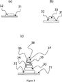
前述の3つの例では、針状構造体を引き出すために2つの面を離すように移動させる方法を用いた。ステンシル塗布や接触印刷等の印刷方法は、針状構造体を製造するべく、様々な大きさの小滴を付着させるために、あるいは次々に同じ大きさの小滴を付着させるために用いることができる。このような方法の一例として、図3を参照する。図3では、UV硬化性接着剤の形態の非固体物質の第1部分32が、自動液体操作システム(図示せず)を用いて第1の面31上に付着される((a)参照)。
【0078】
その後、物質は、UV源(図示せず)を用いて硬化させられ、または、少なくとも部分的に硬化させられる。第2の部分33は、物質の第1の部分32の上に付着させられ、引き続き前述のように硬化させられる((b)参照)。このプロセスは、幾つかの部分32、33、34、35、36、37及び38が次々に重ねられるまで繰り返される((c)参照)。各部分の体積は、直下に位置する部分よりも小さくなっている。このようにして、円錐状または針状の固体構造体を形成できる。
【0079】
物質の複数の部分を順次付着させることによる針状構造体の製造方法のさらに別の例を、図4に示す。ステンシル49が、第1の面41に近づけられる((a)参照)。第1の面41は、可撓性基板の上面により設けられる。ステンシル49は1cm2当たり約1000個の孔を設けられ、各々の直径が100μmである。わかりやすいように、ここでは2つの孔48a及び48bのみを示す。非固体物質はこの場合UV硬化性アクリレート42であり、ステンシル49の上面49a上に付着させられ、スキージ50を用いて拭き広げられる。この拭き広げすなわちワイピング(wiping)操作により、アクリレート42は孔48a及び49b内に押し込まれ、そしてステンシル49が第1の面41に対して押し付けられる。アクリレート42は第1の面41に接着することにより、ステンシル49が第1の面41から取り去られたとき((b)参照)、アクリレートの部分51a、51bが第1の面41上に残る。アクリレートの部分51a、51bは、UVスポット源56から照射されるUV照射(概略的に符号57で示す)に曝されることにより硬化させられ((c)参照)、固体の構造体53a、53bを形成する。ステンシル49が再び置かれて、更に別の非固体物質42の部分を既存の構造体53a、53bの上に付着させることができる。上述の図4(a)、(b)、(c)のステップをさらに繰り返すことにより、高さ約0.7mm及び直径約20μmの針状構造体52a、52bのアレイを形成することができた。この方法で製造される針のアレイは、人間の角質層(in vitro)を突き刺すことができる。
【0080】
この技術を用いて、材料の粘弾性、孔の大きさ及びスキージ速度やz軸方向の動き等の変数を変化させることにより、針の高さをどのような大きさにも増すことができ、また、先端直径を変えることができる。
【0081】
図3及び図4により説明した順次付着の技術は、前述の針引き出し法と組み合わせてもよい。これらの技術はまた、組成を変えた針を製造するために利用できる。例えば、1つの成分の材料により形成されたロッド状または他の構造を、別の成分の針の内側に形成することができる。この内側の構造は、多孔性材料で形成してもよく、マイクロ針を通して通過できるように解離可能としてもよい。
【図面の簡単な説明】
【0082】
【図1】非固体材料からのマイクロ針の引き出しを含む本発明の第1の実施例を示す図である。
【図2】非固体材料からのマイクロ針の引き出しを含む本発明の第2の実施例を示す図である。
【図3】非固体材料の小滴の順次付着によりマイクロ針を形成することを含む本発明の第3の実施例を示す図である。
【図4】複数の非固体材料を次々に付着させるためにステンシルを用いてマイクロ針を形成することを含む本発明の第4の実施例を示す図である。【Technical field】
[0001]
The present invention relates to a method for manufacturing a fine structure, and particularly relates to a microneedle or a microimplant, but is not limited to use in the pharmaceutical industry.
[Background]
[0002]
The administration of a transdermal drug is an important route for drug activity, but the epidermis of the skin is a layer called a stratum corneum having a thickness of 10 to 20 μm, which is an effective barrier against many chemical substances. ing. For this reason, the number of pharmaceutically active substances that can penetrate the skin and penetrate into the body is very limited, and depends on factors such as polarity, logP, and molecular size. At the same time, many drugs have been synthesized that are not suitable for oral administration (eg, due to instability in the gastrointestinal tract or the first pathway of liver metabolism). Thus, the skin, though uncertain, is an attractive route of drug administration that is efficacious in these tissues, as are drugs that act on the skin.
[0003]
Several methods have been developed to successfully manipulate the barrier function of the skin for drug penetration into the body and for removal from the body (for testing purposes). These methods include an ultrasonic introduction method, an ion introduction method, and a micro needle method. U.S. Patent No. 6,099,077 discloses the use of microneedles to facilitate drug administration through the skin. A microneedle is preferred in that it allows a drug to pass through the subject by making a hole in the stratum corneum, but does not induce a pain reaction. This is because the micro needle does not enter the dermis of the skin with nerve cells.
[0004]
Several methods have been proposed for the production of microneedles.
[Patent Document 1]
U.S. Pat. No. 3,964,482
[Patent Document 2]
US Pat. No. 6,558,361
[Patent Document 3]
International Publication 2004/062899
DISCLOSURE OF THE INVENTION
[Problems to be solved by the invention]
[0005]
All of these methods require time and expensive equipment to manufacture microneedles. For example, mold molding has another problem that the quality of microneedles is limited by the quality of the master mold and the life of the mold. Furthermore, there is a problem with mold forming when the needle has a high aspect ratio. Such a mold is difficult to fill, and the needle formed from the mold may not be easily removed.
The present invention aims to solve at least some of these problems in the prior art.
[Means for Solving the Problems]
[0006]
A first aspect of the present invention is a method of manufacturing a microneedle or a microimplant,
(I) depositing a substance on the first surface;
(Ii) forming a solid needle-like structure from the substance.
[0007]
This provides an effective and generally inexpensive method for manufacturing microneedles.
In step (i), a portion or a droplet of material is deposited on the first surface. This facilitates the sequential deposition of these parts or droplets, for example to produce microneedles or needle-like structures drawn from one part or one droplet. As an alternative to intermittent portions or droplets, a continuous film or layer of material may be deposited on the first surface.
[0008]
The first surface is preferably a solid surface.The
[0009]
Step (i) may comprise depositing the material in a non-solid form. Such non-solid materials may flow or be flowable.
[0010]
The substance in non-solid form may be, for example, a liquid, gel, emulsion, cream, paste or thixotropic material. The non-solid form of the material may include, for example, a solid in particulate form. These particles may be suspended or dispersed in a carrier to make the bulk material non-solid.
[0011]
Step (i) includes depositing a solid form of the material. Such materials may not flow. An example of this step is the deposition of solid material by laser printing.
[0012]
If the material is deposited on the first surface in a non-solid form, the step of forming a solid from the material includes, for example, exposing the material to ultraviolet radiation to form a solid polymer, forming a solid. Therefore, it may include removing the solvent and curing after a while (for example, if the non-solid substance is an epoxy resin divided into two, it cures to form a solid over time).That is, the method may not include the use of molding.A solid needle-like structure may not have (and often will not have) the same chemical composition as a non-solid material.
Gazette
[0013]
Step (ii) may comprise depositing another part or another droplet of the substance on the first part or first droplet of the substance. This allows acicular structures to be stacked by depositing one part of the substance on another part. Furthermore, the needle-like structure can be quickly formed using an automatic liquid deposition technique.
[0014]
If the first portion or droplet is deposited in a non-solid form, it is preferred that the first portion or droplet is at least partially solidified prior to the deposition of the next portion or droplet of material. To partially solidify the first part or droplet of the substance, the first part or droplet is exposed to, for example, electromagnetic radiation or simply waited for a predetermined time before the next part or droplet is deposited. Also good.
[0015]
Either or both of the first part and the second part of the material may be deposited in solid form. This facilitates the production of microneedles using a given printing technique, such as laser printing.
[0016]
Suitably the volume of the second droplet or second part is smaller than the first droplet or first part. Thereby, manufacture of a needle-like structure becomes easy.
[0017]
Needle-like structures are formed by depositing portions or droplets of material on top of each other.
[0018]
Step (ii) may comprise depositing successive portions or droplets of the substance on the first portion or droplet one after the other. Where one or more of the portions or droplets are deposited in a non-solid form, the one or more portions or droplets are at least partially before being further overlaid with a portion or droplet of material thereon. It is preferably solidified. Where one or more of the portions or droplets are deposited in a non-solid form, it is preferred that each portion or each droplet be deposited in a non-solid form. Thereby, manufacture of a needle-like structure becomes easy. In this case, it is preferred that the volume of the latter part or droplet is smaller than the volume of the part or droplet placed directly below.
[0019]
In addition to or in place of depositing portions or droplets one after the other as described above, step (ii) provides a second surface in contact with the (preferably non-solid) material and has a needle-like structure. It may include moving the first surface and the second surface relative to each other to form a body. This needle withdrawal is particularly effective when the material is in a non-solid form. Withdrawing the needle can be a relatively simple and quick and automatic process. For example, the method of the present invention includes depositing one or more portions of a material using a continuous deposition method as described above, and then withdrawing a needle-like structure from the material.
[0020]
Step (i) applies a portion or droplet of non-solid material onto the second surface, and the second surface of the first surface such that the portion or droplet of non-solid material contacts the first surface. Move nearbyThat is, the second surface is brought closer to the first surfaceYou may include that.This causes a portion or droplet of non-solid material to contact the first surface.Providing the non-solid material on the second surface can be performed, for example, by placing the non-solid material in a container and contacting the second surface with the non-solid material in the container. This allows the second surface to remove the substance from the container and place it on the first surface before withdrawing the needle.Further, in order to provide a portion or a droplet of a non-solid substance on the second surface, a non-solid substance accumulation part may be provided on the second surface and the second surface may be brought into contact with the non-solid substance.As another example, an opening or hole is provided in the second surface through which a non-solid material is passed to deposit the material (which can be a discontinuous portion or droplet) on the second surface.To form parts or droplets of the substance on the second surface.May be.
[0021]
As another example, step (i) may comprise depositing a non-solid material on the first surface without the second surface. Non-solid materials may be deposited in the form of parts or droplets, or as a continuous film or layer.
[0022]
As yet another example, in step (i), following the movement of the second surface to the vicinity of the first surface, the non-solid material and the second surface are placed by placing the non-solid material on the first surface. A contact can be made between the two surfaces. This can be done by introducing a substance through an opening provided at or near the first surface itself or an opening provided at or near the second surface itself.
[0023]
The second side is solidByCan be provided.
[0024]
When the method of the present invention includes moving the second surface relative to the first surface, step (ii) sequentially (a) moves the first surface and the second surface relative to each other. The method may include a step of forming a needle-like structure, and a step (b) of forming a solid needle-like structure. While the solid needle-like structure is formed, contact between the material and the second surface is maintained. As another example, the second surface may be removed from the material after step (a) and before step (b).
[0025]
Step (ii) may include forming a solid needle-like structure while moving the first surface and the second surface relative to each other.
[0026]
Material deposition can be done using printing methods such as stencil deposition, contact printing (eg pin transfer), and electronic printing such as gravure, offset or xerographic and laser printing, inkjet or bubble printing. There are other printing methods such as flexography, magnetography, and direct charge deposition. Such a method can be conveniently used to deposit a first portion or droplet of material (in solid or non-solid form). These methods can be conveniently used to form a needle-like structure by attaching a plurality of portions or droplets one after another.
[0027]
Where those portions or droplets are deposited in a non-solid form, it is preferred that the portion or droplets at least partially solidify before the next portion or droplet of material is deposited thereon. is there.
[0028]
Step (i) comprises at least oneHoleProviding a stencil comprising: at least one thereofHoleThrough which the substance is deposited (preferably in a non-solid form) on the first surface. At least oneHoleDepositing the substance through (preferably in a non-solid form) means that the substance spontaneously has its at least oneHoleSubstance (rather than letting it pass)HoleCan be done by pushing into This can be done, for example, by depositing a substance on the stencil, covering the stencil, and at least one of theHoleCan be done by wiping and spreading the material to cover.
[0029]
Step (ii) includes moving the stencil relative to the first surface, thereby forming a needle-like structure. In this way, the stencil acts as the second surface as described above. The needle-like structure may be solidified as described above.
[0030]
As another example, step (ii) includes moving the stencil relative to the first surface, bringing the first surface closer to the second surface, so that the second surface contacts the material and the second surface Forming a needle-like structure by moving the first surface relative to the first surface.
[0031]
Step (ii) may comprise providing a stencil with at least one opening and depositing portions or droplets of material (preferably in non-solid form) through at least one opening of the stencil. . If one part or droplet is deposited in a non-solid form, it is preferred that the part or droplet is at least partially solidified before the next part or droplet of material is deposited thereon. . This includes, for example, depositing the material on the stencil in a non-solid form, wiping the material over at least one opening, separating the stencil and the first surface from each other, solidifying the material, And wiping the material in a non-solid form over the at least one opening.
[0032]
The deposition of the substance parts or droplets may be performed by one or more ink jet printing, screen printing or micropipette. These methods can be conveniently used to rapidly produce microneedles and rows of microneedles.
[0033]
The deposition of the substance (and preferably a portion or droplet of a non-solid substance) may be performed by an automated operating system. The automated operating system can use one or more of piezoelectric valves, solenoid valves, syringe pumps, microelectromechanical elements, or air or other gas release means. These are typical of convenient means of controlling the deposition of a substance and are particularly applied when the substance is to be deposited in parts or droplets.
[0034]
The material deposition may be performed by a microarrayer or other automatic contact printing device. These are typical of convenient means of controlling the deposition of a substance and are particularly applied when the substance is to be deposited in parts or droplets.
[0035]
The first surface may be a part of a transdermal patch or a precursor thereof.
[0036]
The solid acicular structure may be either or both of an organic polymer and a silicone polymer, and includes an epoxy resin, an acrylic resin, and a silicone resin.
[0037]
Instead of or in addition to this, the solid acicular structure may be a metal such as titanium. Solid needle-like structure is goldGenusAnd non-metallic mixtures (eg, silica). The needle may be silicon (eg, porous silicon), ceramic or mineral.
[0038]
The solid acicular structure may be silica.
[0039]
Further, suitable materials include UV curable plastics such as acrylate and urethane / acrylate, biodegradable resins such as polylactic acid, or biodegradable materials. Any combination of materials can be used to form the needle. For example, the base of the needle is formed of an acrylate polymer, and one or more other layers are made of other materials such as polylactic acid, or a material that easily disintegrates so that the tip of the needle can remain in living tissue. It may be formed.
[0040]
These methods may include forming grooves or holes in the needle-like structure by inserting long moldings into the material prior to solidification. Such grooves are useful for dispensing fluid through the needle to the object or product into which the needle is inserted.
[0041]
The solid acicular structure may be porous. The porous needle, for example, by using a substance that spontaneously forms a solid needle-like structure having a porous structure by allowing gas to pass through the needle-like structure in the process of forming the needle-like structure, By using a material that removes a predetermined component from the solid needle-like structure (by dissociation, combustion or other methods), or using a material that forms a porous mesh or fiber in the formation of the solid needle-like structure Or a combination thereof. Such porosity is useful for administering fluid through the needle to the object or product into which the needle is inserted.
[0042]
It may further comprise introducing a dopant into the material such that the resulting solid later releases the dopant.
[0043]
Step (i) or (ii) may comprise depositing a catalyst or other reaction promoter. For example, a catalyst that cures the material may be deposited first on the first surface, and the material may be deposited on the catalyst in a non-solid form. The catalyst initiates curing upon contact with the material.
[0044]
The acicular structure may be wholly or partially biodegradable.
[0045]
The acicular structure may be easily separable from the first surface. This facilitates movement of the needle from the first surface to the other surface. It is desirable that the needle-like structure can be easily removed during use.
[0046]
The solid needle-like structure may be easily broken so that a first part combined with the first surface and another separate second part occur.
[0047]
Forming a solid needle-like structure from a non-solid material can include cooling the material, heating the material, aging the non-solid material or exposing it to electromagnetic radiation (usually ultraviolet light), or these One or more combinations may be included. Cooling of the substance can spontaneously form a solid. Heating can release the solvent from the material and form a solid needle-like shape. Exposing the material to electromagnetic radiation can cause a solid to form, for example, when the non-solid material is in the form of an ultraviolet curable resin or adhesive. Aging can, for example, form a solid when the material is a two-part epoxy resin in its non-solid form.
[0048]
The needle may be about 10 μm to 3 mm long, preferably longer than 100 μm, more preferably shorter than 1 mm. Most preferably, the length of the needle is 200 μm to 400 μm. Such a length of extension minimizes reaching the painful nerve dermis. The suitable length may vary depending on the biological layer to be pierced by the span length. For example, the mucosal layer may require a different delivery length than the stratum corneum. Furthermore, in the case of a microneedle intended to penetrate the human stratum corneum, the preferred microneedle length depends on the anatomical location where the microneedle is to be used. This is because the stratum corneum thickness can vary at different anatomical locations.
[0049]
Microneedles are optimally capable of penetrating ecological barriers, the stratum corneum of humans and animals. Furthermore, the method is suitable as a method of forming a device for drilling an ecological barrier.
[0050]
The first surface is preferably provided by a substrate that forms a part of the transdermal patch. Alternatively, the first surface may be provided by an adhesive surface of paper, glass, plastic, adhesive semipermeable membrane, metal and pressure sensitive tape.
[0051]
The solid needle-like structure may contain a pharmaceutically active substance. This is done by introducing the pharmaceutically active substance into the liquid before solidification or after solidification.
[0052]
The first surface on which the solid needle-like structure of the present invention is placed may be provided by a column, a protrusion, or the like. Therefore, the method of the present invention can be used to form microneedles on an existing needle-like structure or protrusion structure.
[0053]
The solid acicular structure may be conical. The solid needle-like structure may be pyramidal (eg, with three or four sides converging at one point). The solid needle-like structure may be bent. This can be done, for example, by using the above-described needle drawer and by forming a bent shape by moving the first surface and the second surface relative to each other. The solid acicular structure may be provided with a hook. For example, it can be performed by using the above-described needle drawer and by moving the first surface and the second surface relative to each other to form a hook shape.
[0054]
In a second aspect of the invention, a method for manufacturing an array of microneedles is provided. This method
(I) depositing a substance on the first surface;
(Ii) forming a solid needle-shaped array from the material.
[0055]
The method according to the second aspect of the present invention preferably does not utilize molding.
[0056]
Step (i) may include depositing a first plurality of portions or droplets of material on the first surface.
[0057]
Step (i) includes depositing the material in a non-solid or solid form.
[0058]
The manufacture of an array of multiple parts or droplets is obtained by sequentially depositing multiple parts or droplets on the first surface. Alternatively, multiple portions or an array of droplets corresponding to the array of microneedles may be deposited simultaneously on the first surface.
[0059]
Step (ii) may comprise depositing a second plurality of portions or droplets of material on the first plurality of portions or droplet array of materials. A third plurality of portions or an array of droplets may be deposited over the second plurality of portions or droplets. As described above with respect to the manufacture of a single microneedle, the array of needle-like structures is performed by sequentially depositing multiple portions or droplets of material. The method used for the array may include features as described above for the method of the first aspect of the invention.
[0060]
The material may be deposited in a non-solid form, and step (ii) includes providing a second surface that contacts the material and moving the first surface and the second surface relative to each other to move the acicular structure. Forming may also be included. Accordingly, the array of needle-like structures may be extracted from the material as described above with respect to the first aspect of the invention. This material is deposited as discrete portions or droplets or as a continuous film or layer. Step (ii) may comprise contacting the second surface array with a non-solid material and withdrawing the material into the array of needle-like structures. Alternatively, a plurality of microneedle structures are provided by contacting the second surface with a plurality of portions or droplet arrays and withdrawing the plurality of portions or droplets into an array of needle-like structures. Or from an array of droplets. This can be done with a single substantially flat second surface.
[0061]
Alternatively, one or more second surfaces may be used to sequentially draw a plurality of needle-like structures from a substance (optionally attached as a plurality of portions or droplets). Those one or more second surfaces are moved to produce an array of needles.
[0062]
The method of the second aspect of the invention may include the features described above with respect to the method of the first aspect of the invention. For example, a stencil may be used to provide the array as described with respect to the first aspect of the invention.
[0063]
According to the third aspect of the present invention, without using molding, the liquid is deposited on the first surface and subsequently or solidified by simultaneous curing or other solidification to form a solid needle-like shape, A method is provided for manufacturing microneedles or microimplants alone or in an array.
[0064]
The method of the third aspect of the invention may include the features described above with respect to the method of the first aspect of the invention.
[0065]
The present invention also provides an apparatus for application to an ecological barrier, the apparatus comprising a substrate provided with one or more microneedles formed by the method of the first, second or third aspect of the present invention. Have. The apparatus may have a first surface to which one or more microneedles formed by the method of the first, second or third aspects of the invention are attached. The first surface may be flexible. This device may be a transdermal patch, for example. The device may have a sensor, pump, or drug delivery device. This device comprises means for inserting one or more microneedles into an ecological barrier. The device may include a drug eluting stent.
BEST MODE FOR CARRYING OUT THE INVENTION
[0066]
A first embodiment of the present invention will be described with reference to FIG. In FIG. 1a, a
[0067]
The
[0068]
Instead of introducing the
[0069]
The relative movement between the first surface 1 and the
[0070]
The acicular structure may be solidified by cooling or by curing. This can be done, for example, by using a curable liquid of an ultraviolet curable acrylate adhesive and exposing the liquid to ultraviolet light to cure the adhesive. The liquid may be an epoxy resin. In this case, a long structure can be manufactured by moving the first surface relative to the second surface. This long structure may be cured by aging. Thereafter, the second surface can be removed from the first surface by separating the long structure. By this separation operation, a needle-like structure is formed on the first surface.
[0071]
A second embodiment of the present invention will be described with reference to FIG. A spot forming device, such as a microarray, can be used to place the liquid on the surface that acts as the storage. A pin P having a diameter of 0.4 mm is brought close to the lower stationary support portion. By moving the accumulation of non-solid material (in this case, a large spot of UV curable acrylate adhesive) to form the micro needle onto the transfer stage, the head of the pin P is in the material for 3 seconds. The liquid 12 is soaked in contact with the tip of the pin P. The
[0072]
Needles were made with a variety of solid surfaces including paper, glass, plastic, transdermal drug delivery patches, adhesive semipermeable membranes, and the adhesive side of pressure sensitive adhesive tape. By using a pin with a large diameter, a sharp needle with a height exceeding 1 mm could be produced. With a small diameter pin, a needle with a height of 250 μm could be produced.
[0073]
A third embodiment of the present invention will be described. A spot of viscous epoxy resin is placed on the second glass surface using contact printing. Thereafter, the first glass surface was placed on a stage movable in the z direction. By bringing the first glass surface closer to the second flexible glass surface, a droplet of epoxy resin contacted the second glass surface. During the curing of the resin, the first and second glass surfaces were slowly pulled apart to pull out the needle-like structure from each surface. After 3 hours, the resin hardened and the crosslinks remaining between the two surfaces were cut with scissors. As a result, very sharp and hard microneedle structures protruded perpendicularly to the two glass surfaces. During curing, the tip of the needle is easily bent, so it can be bent into a curved surface and can also have a hook structure. A loop can also be formed by pressing a flexible tip against the glass surface. These shapes are fixed after curing is complete.
[0074]
In the above example, the second surface may have a lower surface region for contacting the liquid. Thereby, a fine acicular structure can be manufactured. The second surface can be provided by the tip of a pointed object, such as a pin, typically 0.4 mm in diameter.
[0075]
The second surface may remain in needle-extracting contact with the liquid, depending on the liquid and the surface properties of the second surface. This can be achieved, for example, by using an adhesive as the liquid. Alternatively, the second surface may be kept in contact with the liquid by using a vacuum with the second surface. Alternatively, the second surface may be provided with holes through which liquid flows by capillary action.
[0076]
The method further includes a needle-like structure that is bent or tilted with respect to the first surface by moving the first surface relative to the second surface prior to solidification or curing or is in the form of a hook bearing. Forming may be included.
[0077]
In the above-described three examples, a method of moving the two surfaces apart to extract the needle-like structure is used. Printing methods such as stencil coating and contact printing can be used to produce needle-like structures, to deposit droplets of various sizes, or to deposit droplets of the same size one after another. it can. As an example of such a method, reference is made to FIG. In FIG. 3, a
[0078]
The material is then cured using a UV source (not shown) or at least partially cured. The
[0079]
FIG. 4 shows still another example of a method for manufacturing a needle-like structure by sequentially attaching a plurality of portions of a substance. The
[0080]
Using this technique, the height of the needle can be increased to any size by changing variables such as viscoelasticity of the material, hole size and squeegee speed and movement in the z-axis direction, Also, the tip diameter can be changed.
[0081]
The sequential deposition technique described with reference to FIGS. 3 and 4 may be combined with the above-described needle withdrawal method. These techniques can also be used to produce needles of varying composition. For example, a rod or other structure formed from one component material can be formed inside another component needle. This inner structure may be formed of a porous material and may be dissociable so that it can pass through the microneedle.
[Brief description of the drawings]
[0082]
FIG. 1 shows a first embodiment of the present invention that includes the withdrawal of microneedles from a non-solid material.
FIG. 2 shows a second embodiment of the present invention including the withdrawal of microneedles from a non-solid material.
FIG. 3 illustrates a third embodiment of the present invention that includes forming microneedles by sequential deposition of droplets of non-solid material.
FIG. 4 illustrates a fourth embodiment of the present invention that includes forming microneedles using a stencil to sequentially deposit a plurality of non-solid materials.
Claims (13)
(ii)前記物質から固体の針状構造体を形成するステップとを含む、マイクロ針またはマイクロインプラントを製造する方法であって、
前記ステップ(i)が前記第1の面上に物質からなる第1の部分または小滴を付着させることを含み、かつ、前記ステップ(ii)が物質からなる前記第1の部分または小滴の上に物質からなる第2の部分または小滴を付着させることを含む、マイクロ針またはマイクロインプラントを製造する方法。A method of manufacturing a microneedle or a microimplant comprising the steps of (i) depositing a substance on a first surface that is a solid surface, and (ii) forming a solid needle-like structure from the substance. And
Wherein said step (i) is to deposit a first portion or droplet of a substance on said first surface, and wherein step (ii) is of the first portion or droplet of a substance It comprises depositing a second portion or droplet of a substance on a method of manufacturing a micro-needle or micro-implants.
(ii)前記物質から固体の針状構造体のアレイを形成するステップとを含む、
マイクロ針のアレイを製造する方法であって、
前記ステップ(i)が前記第1の面上に物質からなる断続的な複数の第1の部分または小滴のアレイを付着させることを含み、かつ、前記ステップ(ii)が物質からなる前記複数の第1の部分または小滴のアレイの上に、物質からなる複数の第2の部分または小滴を付着させることを含む、マイクロ針のアレイを製造する方法。(I) depositing a substance on the first surface which is a solid;
(Ii) forming an array of solid needle-like structures from the material,
A method of manufacturing an array of microneedles, comprising:
The method comprising depositing an array of intermittent multiple first portions or droplets step (i) is made of a material on the first surface, and said plurality of said step (ii) is made of a material method on the first portion or droplet array, comprises attaching a plurality of second portions or droplets made of a material, to produce an array of micro-needles.
Applications Claiming Priority (5)
| Application Number | Priority Date | Filing Date | Title |
|---|---|---|---|
| GBGB0418246.5A GB0418246D0 (en) | 2004-08-16 | 2004-08-16 | Method for producing microneedles, microimplants and arrays thereof |
| GB0418246.5 | 2004-08-16 | ||
| GB0427762.0 | 2004-12-17 | ||
| GBGB0427762.0A GB0427762D0 (en) | 2004-12-17 | 2004-12-17 | Device and method for transport across barrier |
| PCT/GB2005/003224 WO2006018642A1 (en) | 2004-08-16 | 2005-08-16 | Method of producing a microneedle or microimplant |
Publications (3)
| Publication Number | Publication Date |
|---|---|
| JP2008509771A JP2008509771A (en) | 2008-04-03 |
| JP2008509771A5 JP2008509771A5 (en) | 2008-08-28 |
| JP5082053B2 true JP5082053B2 (en) | 2012-11-28 |
Family
ID=35447243
Family Applications (1)
| Application Number | Title | Priority Date | Filing Date |
|---|---|---|---|
| JP2007526569A Expired - Fee Related JP5082053B2 (en) | 2004-08-16 | 2005-08-16 | Manufacturing method of microneedle or microimplant |
Country Status (7)
| Country | Link |
|---|---|
| US (1) | US8192787B2 (en) |
| EP (3) | EP1786580B1 (en) |
| JP (1) | JP5082053B2 (en) |
| AT (1) | ATE490037T1 (en) |
| DE (1) | DE602005025138D1 (en) |
| ES (1) | ES2463818T3 (en) |
| WO (1) | WO2006018642A1 (en) |
Cited By (1)
| Publication number | Priority date | Publication date | Assignee | Title |
|---|---|---|---|---|
| KR20170131283A (en) * | 2016-05-20 | 2017-11-29 | 주식회사 라파스 | Manufacturing method of micro needle |
Families Citing this family (28)
| Publication number | Priority date | Publication date | Assignee | Title |
|---|---|---|---|---|
| US7699819B2 (en) | 2006-02-21 | 2010-04-20 | The Hong Kong University Of Science And Technology | Molecular sieve and zeolite microneedles and preparation thereof |
| CN100460028C (en) * | 2006-12-08 | 2009-02-11 | 中国科学院上海微系统与信息技术研究所 | Miniature needle array for medicine transmission and its making process |
| EP2127693A1 (en) * | 2007-01-29 | 2009-12-02 | Medrx Co., Ltd. | Process for producing microneedle of thermosensitive substance |
| JP4959363B2 (en) * | 2007-02-14 | 2012-06-20 | 凸版印刷株式会社 | Manufacturing method of needle-shaped body |
| JP4978243B2 (en) * | 2007-03-06 | 2012-07-18 | 凸版印刷株式会社 | Needle-like body and method for producing needle-like body |
| US8366677B2 (en) * | 2007-08-06 | 2013-02-05 | Transderm, Inc. | Microneedle arrays formed from polymer films |
| KR20100037389A (en) * | 2008-10-01 | 2010-04-09 | 연세대학교 산학협력단 | Solid microstructure with multi-controlled release and process for preparing the same |
| WO2010039006A2 (en) * | 2008-10-02 | 2010-04-08 | 연세대학교 산학협력단 | Method of manufacturing solid microstructure and solid microstructure manufactured based on same |
| WO2010137319A1 (en) * | 2009-05-27 | 2010-12-02 | 株式会社メドレックス | Method for producing pinholder-shaped microneedles, and microneedle |
| US8834423B2 (en) | 2009-10-23 | 2014-09-16 | University of Pittsburgh—of the Commonwealth System of Higher Education | Dissolvable microneedle arrays for transdermal delivery to human skin |
| KR101254240B1 (en) * | 2010-12-17 | 2013-04-12 | 주식회사 라파스 | Process for preparing microstructures |
| KR101180032B1 (en) | 2010-07-12 | 2012-09-05 | 인싸이토(주) | Method for manufacturing Hollow Microneedle with Controlled External Appearance Characteristics |
| EP4112112A1 (en) | 2012-05-01 | 2023-01-04 | University of Pittsburgh - Of the Commonwealth System of Higher Education | Tip-loaded microneedle arrays for transdermal insertion |
| US10245436B2 (en) | 2012-07-17 | 2019-04-02 | Stimwave Technologies Incorporated | Miniature implantable device and methods |
| WO2014153228A1 (en) * | 2013-03-14 | 2014-09-25 | Perryman Laura Tyler | Miniature implantable device and methods |
| WO2014129816A1 (en) * | 2013-02-22 | 2014-08-28 | 연세대학교 산학협력단 | Method for manufacturing microstructure using negative pressure and microstructure manufactured therefor |
| US20160279401A1 (en) | 2015-03-27 | 2016-09-29 | Allergan, Inc. | Dissolvable microneedles for skin treatment |
| WO2016149673A1 (en) | 2015-03-18 | 2016-09-22 | University Of Pittsburgh - Of The Commonwealth System Of Higher Education | Bioactive components conjugated to substrates of microneedle arrays |
| JP2016195651A (en) * | 2015-04-02 | 2016-11-24 | 日本写真印刷株式会社 | Microneedle sheet |
| WO2017066768A1 (en) | 2015-10-16 | 2017-04-20 | University Of Pittsburgh-Of The Commonwealth System Of Higher Education | Mullti-component biio-active drug delivery and controlled release to the skin by microneedle array devices |
| US11744889B2 (en) | 2016-01-05 | 2023-09-05 | University of Pittsburgh—of the Commonwealth System of Higher Education | Skin microenvironment targeted delivery for promoting immune and other responses |
| WO2017140239A1 (en) | 2016-02-15 | 2017-08-24 | Shanghai Jiao Tong University | Method to print microneedle patches rapidly |
| KR101816922B1 (en) * | 2016-05-20 | 2018-01-09 | 주식회사 라파스 | Manufacturing method of micro needle |
| US11065428B2 (en) | 2017-02-17 | 2021-07-20 | Allergan, Inc. | Microneedle array with active ingredient |
| CN109420245A (en) * | 2017-08-30 | 2019-03-05 | 优微(珠海)生物科技有限公司 | The manufacturing method of soluble micropin |
| GB2586474A (en) * | 2019-08-20 | 2021-02-24 | Innoture Ip Ltd | Method of manufacturing microstructures |
| GB2586475A (en) * | 2019-08-20 | 2021-02-24 | Innoture Ip Ltd | Methods |
| CN112618922A (en) * | 2020-12-30 | 2021-04-09 | 上海心至医疗科技有限公司 | Preparation method of drug balloon, prepared drug balloon and application thereof |
Family Cites Families (54)
| Publication number | Priority date | Publication date | Assignee | Title |
|---|---|---|---|---|
| US3964482A (en) | 1971-05-17 | 1976-06-22 | Alza Corporation | Drug delivery device |
| JPS5428369A (en) | 1977-08-03 | 1979-03-02 | Yamakawa Tsuneko | Method of forming needleelike projection of thermoplastic resin on sheet |
| JPS6216132A (en) * | 1985-07-12 | 1987-01-24 | Shimano & Co Ltd | Manufacture of angling rod equipped with slip-proof projection |
| US5309909A (en) * | 1992-05-22 | 1994-05-10 | Physio-Control Corporation | Combined skin preparation and monitoring electrode |
| US7422574B2 (en) | 1995-05-19 | 2008-09-09 | Applied Tissue Technologies, Llc | Microseeding device for gene delivery by microneedle injection |
| JP2002517300A (en) | 1998-06-10 | 2002-06-18 | ジョージア テック リサーチ コーポレイション | Microneedle devices and methods of manufacture and uses thereof |
| US6689103B1 (en) | 1999-05-07 | 2004-02-10 | Scimed Life System, Inc. | Injection array apparatus and method |
| ATE462468T1 (en) | 1999-06-04 | 2010-04-15 | Georgia Tech Res Inst | DEVICES FOR ENLARGED MICRONEEDLES PENETRATION IN BIOLOGICAL SKIN LAYERS |
| US6743211B1 (en) * | 1999-11-23 | 2004-06-01 | Georgia Tech Research Corporation | Devices and methods for enhanced microneedle penetration of biological barriers |
| US6379324B1 (en) | 1999-06-09 | 2002-04-30 | The Procter & Gamble Company | Intracutaneous microneedle array apparatus |
| US6312612B1 (en) * | 1999-06-09 | 2001-11-06 | The Procter & Gamble Company | Apparatus and method for manufacturing an intracutaneous microneedle array |
| US6623457B1 (en) | 1999-09-22 | 2003-09-23 | Becton, Dickinson And Company | Method and apparatus for the transdermal administration of a substance |
| US8465468B1 (en) | 2000-06-29 | 2013-06-18 | Becton, Dickinson And Company | Intradermal delivery of substances |
| US6511463B1 (en) | 1999-11-18 | 2003-01-28 | Jds Uniphase Corporation | Methods of fabricating microneedle arrays using sacrificial molds |
| AU2736501A (en) | 1999-12-30 | 2001-07-16 | Redeon, Inc. | Stacked microneedle systems |
| AU2001245472A1 (en) | 2000-03-09 | 2001-09-17 | Nanopass Ltd. | Systems and methods for the transport of fluids through a biological barrier andproduction techniques for such systems |
| US6558361B1 (en) | 2000-03-09 | 2003-05-06 | Nanopass Ltd. | Systems and methods for the transport of fluids through a biological barrier and production techniques for such systems |
| WO2001091846A2 (en) | 2000-05-26 | 2001-12-06 | The Procter & Gamble Company | Microneedle apparatus used for marking skin and for dispensing semi-permanent subcutaneous makeup |
| WO2001093930A1 (en) | 2000-06-02 | 2001-12-13 | The University Of Utah Research Foundation | Active needle devices with integrated functionality |
| US6440096B1 (en) * | 2000-07-14 | 2002-08-27 | Becton, Dickinson And Co. | Microdevice and method of manufacturing a microdevice |
| EP1311310A4 (en) | 2000-08-21 | 2004-11-24 | Cleveland Clinic Foundation | Microneedle array module and method of fabricating the same |
| US6533949B1 (en) | 2000-08-28 | 2003-03-18 | Nanopass Ltd. | Microneedle structure and production method therefor |
| WO2002028471A1 (en) * | 2000-10-05 | 2002-04-11 | Thomas Marsoner | Medical injection device |
| WO2002045771A2 (en) | 2000-11-09 | 2002-06-13 | Biovalve Technologies, Inc. | Microneedle adapter |
| US9302903B2 (en) | 2000-12-14 | 2016-04-05 | Georgia Tech Research Corporation | Microneedle devices and production thereof |
| GB0030929D0 (en) | 2000-12-19 | 2001-01-31 | Inverness Medical Ltd | Analyte measurement |
| AU2002231207A1 (en) | 2000-12-21 | 2002-07-01 | Biovalve Technologies, Inc. | Microneedle array systems |
| US6663820B2 (en) | 2001-03-14 | 2003-12-16 | The Procter & Gamble Company | Method of manufacturing microneedle structures using soft lithography and photolithography |
| US6591124B2 (en) | 2001-05-11 | 2003-07-08 | The Procter & Gamble Company | Portable interstitial fluid monitoring system |
| US7127284B2 (en) | 2001-06-11 | 2006-10-24 | Mercator Medsystems, Inc. | Electroporation microneedle and methods for its use |
| US6767341B2 (en) | 2001-06-13 | 2004-07-27 | Abbott Laboratories | Microneedles for minimally invasive drug delivery |
| US6881203B2 (en) | 2001-09-05 | 2005-04-19 | 3M Innovative Properties Company | Microneedle arrays and methods of manufacturing the same |
| US8361037B2 (en) | 2001-09-19 | 2013-01-29 | Valeritas, Inc. | Microneedles, microneedle arrays, and systems and methods relating to same |
| WO2003024508A2 (en) | 2001-09-21 | 2003-03-27 | Biovalve Technologies, Inc. | Gas pressure actuated microneedle arrays, and systems and methods relating to same |
| CA2500453A1 (en) | 2001-09-28 | 2003-04-03 | Biovalve Technologies, Inc. | Microneedle with membrane |
| US20030135166A1 (en) | 2001-09-28 | 2003-07-17 | Gonnelli Robert R. | Switchable microneedle arrays and systems and methods relating to same |
| US7429258B2 (en) | 2001-10-26 | 2008-09-30 | Massachusetts Institute Of Technology | Microneedle transport device |
| US6908453B2 (en) | 2002-01-15 | 2005-06-21 | 3M Innovative Properties Company | Microneedle devices and methods of manufacture |
| AU2003205315A1 (en) | 2002-01-22 | 2003-09-02 | Endobionics, Inc. | Methods and kits for delivering pharmaceutical agents into the coronary vascular adventitia |
| GB0201736D0 (en) | 2002-01-25 | 2002-03-13 | Glaxo Group Ltd | DNA dosage forms |
| US7004928B2 (en) | 2002-02-08 | 2006-02-28 | Rosedale Medical, Inc. | Autonomous, ambulatory analyte monitor or drug delivery device |
| JP4090018B2 (en) * | 2002-02-18 | 2008-05-28 | For Head株式会社 | Functional micropile and manufacturing method thereof |
| US7115108B2 (en) | 2002-04-02 | 2006-10-03 | Becton, Dickinson And Company | Method and device for intradermally delivering a substance |
| US6780171B2 (en) * | 2002-04-02 | 2004-08-24 | Becton, Dickinson And Company | Intradermal delivery device |
| GB0216333D0 (en) | 2002-07-13 | 2002-08-21 | Univ Cranfield | Substance - selective polymer membranes |
| EP1523367A1 (en) | 2002-07-19 | 2005-04-20 | 3M Innovative Properties Company | Microneedle devices and microneedle delivery apparatus |
| US7530975B2 (en) | 2002-09-06 | 2009-05-12 | Massachusetts Institute Of Technology | Measuring properties of an anatomical body |
| US20040106904A1 (en) | 2002-10-07 | 2004-06-03 | Gonnelli Robert R. | Microneedle array patch |
| AU2003272053A1 (en) * | 2002-10-13 | 2004-05-04 | Nano Pass Technologies Ltd. | Polymer microneedles |
| IL152271A (en) * | 2002-10-13 | 2006-04-10 | Meir Hefetz | Microneedles structures and production methods |
| EP1583423A4 (en) | 2003-01-16 | 2006-05-10 | Becton Dickinson Co | Intradermal cellular delivery using narrow gauge micro-cannula |
| KR100563330B1 (en) | 2003-01-16 | 2006-03-22 | 포스트마이크로 주식회사 | Method for manufacturing of polymer micro needle array with liga process |
| EP1632263A4 (en) * | 2003-06-10 | 2008-04-30 | Medrx Co Ltd | Process for producing pad base for transdermal drug administration, pad base for transdermal drug administration and needle |
| US7273474B2 (en) * | 2003-06-17 | 2007-09-25 | Industrial Technology Research Institute | Flexible substrate structure for microneedle arrays and its manufacturing method |
-
2005
- 2005-08-16 WO PCT/GB2005/003224 patent/WO2006018642A1/en active Application Filing
- 2005-08-16 ES ES10183463.8T patent/ES2463818T3/en active Active
- 2005-08-16 AT AT05771798T patent/ATE490037T1/en not_active IP Right Cessation
- 2005-08-16 EP EP05771798A patent/EP1786580B1/en active Active
- 2005-08-16 EP EP10183463.8A patent/EP2289646B1/en active Active
- 2005-08-16 DE DE602005025138T patent/DE602005025138D1/en active Active
- 2005-08-16 EP EP10183472A patent/EP2272430A1/en not_active Withdrawn
- 2005-08-16 JP JP2007526569A patent/JP5082053B2/en not_active Expired - Fee Related
- 2005-08-16 US US11/660,341 patent/US8192787B2/en active Active
Cited By (1)
| Publication number | Priority date | Publication date | Assignee | Title |
|---|---|---|---|---|
| KR20170131283A (en) * | 2016-05-20 | 2017-11-29 | 주식회사 라파스 | Manufacturing method of micro needle |
Also Published As
| Publication number | Publication date |
|---|---|
| WO2006018642A1 (en) | 2006-02-23 |
| EP1786580A1 (en) | 2007-05-23 |
| ATE490037T1 (en) | 2010-12-15 |
| EP2289646A1 (en) | 2011-03-02 |
| JP2008509771A (en) | 2008-04-03 |
| EP1786580B1 (en) | 2010-12-01 |
| EP2289646B1 (en) | 2014-02-12 |
| DE602005025138D1 (en) | 2011-01-13 |
| US8192787B2 (en) | 2012-06-05 |
| US20080299290A1 (en) | 2008-12-04 |
| EP2272430A1 (en) | 2011-01-12 |
| ES2463818T3 (en) | 2014-05-29 |
Similar Documents
| Publication | Publication Date | Title |
|---|---|---|
| JP5082053B2 (en) | Manufacturing method of microneedle or microimplant | |
| JP5860453B2 (en) | Composite microneedle array with nanostructures on the surface | |
| CA2686093C (en) | Solvent-cast microneedle arrays containing active | |
| EP2379160B1 (en) | Patch production | |
| US10029081B2 (en) | Molding compact, and manufacturing method for transdermal absorption sheet | |
| JP5020080B2 (en) | Manufacturing method of medical equipment | |
| EP2343101A1 (en) | Stamper for microneedle sheet, method for manufacturing the stamper, and method for manufacturing microneedle using the stamper | |
| JP2010069253A (en) | Transdermal absorption sheet and method for manufacturing the same | |
| JP6565906B2 (en) | Needle-like body manufacturing method and needle-like body | |
| O'Mahony et al. | Accuracy and feasibility of piezoelectric inkjet coating technology for applications in microneedle-based transdermal delivery | |
| JP2009233170A (en) | Method for manufacturing sheet with high aspect ratio structure | |
| ES2357079T3 (en) | PROCEDURE OF PRODUCTION OF A MICRO-NEEDLE OR A MICROIMPLANT. | |
| EP2422836B1 (en) | Medication liquid supporting jig and method of applying medication to micro-needle using same | |
| JP5870551B2 (en) | Manufacturing method of microneedle device | |
| RU2560646C9 (en) | Array of microneedles manufactured by injection-compression moulding and method of moulding array of microneedles |
Legal Events
| Date | Code | Title | Description |
|---|---|---|---|
| A521 | Request for written amendment filed |
Free format text: JAPANESE INTERMEDIATE CODE: A523 Effective date: 20080701 |
|
| A621 | Written request for application examination |
Free format text: JAPANESE INTERMEDIATE CODE: A621 Effective date: 20080701 |
|
| A977 | Report on retrieval |
Free format text: JAPANESE INTERMEDIATE CODE: A971007 Effective date: 20110207 |
|
| A131 | Notification of reasons for refusal |
Free format text: JAPANESE INTERMEDIATE CODE: A131 Effective date: 20110215 |
|
| A601 | Written request for extension of time |
Free format text: JAPANESE INTERMEDIATE CODE: A601 Effective date: 20110506 |
|
| A602 | Written permission of extension of time |
Free format text: JAPANESE INTERMEDIATE CODE: A602 Effective date: 20110513 |
|
| A521 | Request for written amendment filed |
Free format text: JAPANESE INTERMEDIATE CODE: A523 Effective date: 20110614 |
|
| A131 | Notification of reasons for refusal |
Free format text: JAPANESE INTERMEDIATE CODE: A131 Effective date: 20111101 |
|
| A521 | Request for written amendment filed |
Free format text: JAPANESE INTERMEDIATE CODE: A523 Effective date: 20120116 |
|
| A01 | Written decision to grant a patent or to grant a registration (utility model) |
Free format text: JAPANESE INTERMEDIATE CODE: A01 Effective date: 20120612 |
|
| A01 | Written decision to grant a patent or to grant a registration (utility model) |
Free format text: JAPANESE INTERMEDIATE CODE: A01 |
|
| A711 | Notification of change in applicant |
Free format text: JAPANESE INTERMEDIATE CODE: A711 Effective date: 20120712 |
|
| A61 | First payment of annual fees (during grant procedure) |
Free format text: JAPANESE INTERMEDIATE CODE: A61 Effective date: 20120712 |
|
| A521 | Request for written amendment filed |
Free format text: JAPANESE INTERMEDIATE CODE: A821 Effective date: 20120712 |
|
| A521 | Request for written amendment filed |
Free format text: JAPANESE INTERMEDIATE CODE: A523 Effective date: 20120829 |
|
| R150 | Certificate of patent or registration of utility model |
Free format text: JAPANESE INTERMEDIATE CODE: R150 |
|
| FPAY | Renewal fee payment (event date is renewal date of database) |
Free format text: PAYMENT UNTIL: 20150914 Year of fee payment: 3 |
|
| A521 | Request for written amendment filed |
Free format text: JAPANESE INTERMEDIATE CODE: A523 Effective date: 20110614 |
|
| LAPS | Cancellation because of no payment of annual fees |