JP5081886B2 - Non-aqueous electrolyte type lithium ion secondary battery - Google Patents
Non-aqueous electrolyte type lithium ion secondary battery Download PDFInfo
- Publication number
- JP5081886B2 JP5081886B2 JP2009236469A JP2009236469A JP5081886B2 JP 5081886 B2 JP5081886 B2 JP 5081886B2 JP 2009236469 A JP2009236469 A JP 2009236469A JP 2009236469 A JP2009236469 A JP 2009236469A JP 5081886 B2 JP5081886 B2 JP 5081886B2
- Authority
- JP
- Japan
- Prior art keywords
- secondary battery
- ion secondary
- lithium ion
- positive electrode
- lithium
- Prior art date
- Legal status (The legal status is an assumption and is not a legal conclusion. Google has not performed a legal analysis and makes no representation as to the accuracy of the status listed.)
- Active
Links
Images


Classifications
-
- H—ELECTRICITY
- H01—ELECTRIC ELEMENTS
- H01M—PROCESSES OR MEANS, e.g. BATTERIES, FOR THE DIRECT CONVERSION OF CHEMICAL ENERGY INTO ELECTRICAL ENERGY
- H01M4/00—Electrodes
- H01M4/02—Electrodes composed of, or comprising, active material
- H01M4/36—Selection of substances as active materials, active masses, active liquids
- H01M4/58—Selection of substances as active materials, active masses, active liquids of inorganic compounds other than oxides or hydroxides, e.g. sulfides, selenides, tellurides, halogenides or LiCoFy; of polyanionic structures, e.g. phosphates, silicates or borates
- H01M4/5825—Oxygenated metallic salts or polyanionic structures, e.g. borates, phosphates, silicates, olivines
-
- H—ELECTRICITY
- H01—ELECTRIC ELEMENTS
- H01M—PROCESSES OR MEANS, e.g. BATTERIES, FOR THE DIRECT CONVERSION OF CHEMICAL ENERGY INTO ELECTRICAL ENERGY
- H01M4/00—Electrodes
- H01M4/02—Electrodes composed of, or comprising, active material
- H01M4/13—Electrodes for accumulators with non-aqueous electrolyte, e.g. for lithium-accumulators; Processes of manufacture thereof
-
- H—ELECTRICITY
- H01—ELECTRIC ELEMENTS
- H01M—PROCESSES OR MEANS, e.g. BATTERIES, FOR THE DIRECT CONVERSION OF CHEMICAL ENERGY INTO ELECTRICAL ENERGY
- H01M10/00—Secondary cells; Manufacture thereof
- H01M10/05—Accumulators with non-aqueous electrolyte
- H01M10/052—Li-accumulators
- H01M10/0525—Rocking-chair batteries, i.e. batteries with lithium insertion or intercalation in both electrodes; Lithium-ion batteries
-
- H—ELECTRICITY
- H01—ELECTRIC ELEMENTS
- H01M—PROCESSES OR MEANS, e.g. BATTERIES, FOR THE DIRECT CONVERSION OF CHEMICAL ENERGY INTO ELECTRICAL ENERGY
- H01M4/00—Electrodes
- H01M4/02—Electrodes composed of, or comprising, active material
- H01M4/13—Electrodes for accumulators with non-aqueous electrolyte, e.g. for lithium-accumulators; Processes of manufacture thereof
- H01M4/131—Electrodes based on mixed oxides or hydroxides, or on mixtures of oxides or hydroxides, e.g. LiCoOx
-
- H—ELECTRICITY
- H01—ELECTRIC ELEMENTS
- H01M—PROCESSES OR MEANS, e.g. BATTERIES, FOR THE DIRECT CONVERSION OF CHEMICAL ENERGY INTO ELECTRICAL ENERGY
- H01M4/00—Electrodes
- H01M4/02—Electrodes composed of, or comprising, active material
- H01M4/36—Selection of substances as active materials, active masses, active liquids
- H01M4/362—Composites
- H01M4/364—Composites as mixtures
-
- H—ELECTRICITY
- H01—ELECTRIC ELEMENTS
- H01M—PROCESSES OR MEANS, e.g. BATTERIES, FOR THE DIRECT CONVERSION OF CHEMICAL ENERGY INTO ELECTRICAL ENERGY
- H01M4/00—Electrodes
- H01M4/02—Electrodes composed of, or comprising, active material
- H01M4/36—Selection of substances as active materials, active masses, active liquids
- H01M4/48—Selection of substances as active materials, active masses, active liquids of inorganic oxides or hydroxides
- H01M4/50—Selection of substances as active materials, active masses, active liquids of inorganic oxides or hydroxides of manganese
- H01M4/505—Selection of substances as active materials, active masses, active liquids of inorganic oxides or hydroxides of manganese of mixed oxides or hydroxides containing manganese for inserting or intercalating light metals, e.g. LiMn2O4 or LiMn2OxFy
-
- H—ELECTRICITY
- H01—ELECTRIC ELEMENTS
- H01M—PROCESSES OR MEANS, e.g. BATTERIES, FOR THE DIRECT CONVERSION OF CHEMICAL ENERGY INTO ELECTRICAL ENERGY
- H01M4/00—Electrodes
- H01M4/02—Electrodes composed of, or comprising, active material
- H01M4/36—Selection of substances as active materials, active masses, active liquids
- H01M4/48—Selection of substances as active materials, active masses, active liquids of inorganic oxides or hydroxides
- H01M4/52—Selection of substances as active materials, active masses, active liquids of inorganic oxides or hydroxides of nickel, cobalt or iron
- H01M4/525—Selection of substances as active materials, active masses, active liquids of inorganic oxides or hydroxides of nickel, cobalt or iron of mixed oxides or hydroxides containing iron, cobalt or nickel for inserting or intercalating light metals, e.g. LiNiO2, LiCoO2 or LiCoOxFy
-
- H—ELECTRICITY
- H01—ELECTRIC ELEMENTS
- H01M—PROCESSES OR MEANS, e.g. BATTERIES, FOR THE DIRECT CONVERSION OF CHEMICAL ENERGY INTO ELECTRICAL ENERGY
- H01M4/00—Electrodes
- H01M4/02—Electrodes composed of, or comprising, active material
- H01M4/36—Selection of substances as active materials, active masses, active liquids
- H01M4/58—Selection of substances as active materials, active masses, active liquids of inorganic compounds other than oxides or hydroxides, e.g. sulfides, selenides, tellurides, halogenides or LiCoFy; of polyanionic structures, e.g. phosphates, silicates or borates
-
- H—ELECTRICITY
- H01—ELECTRIC ELEMENTS
- H01M—PROCESSES OR MEANS, e.g. BATTERIES, FOR THE DIRECT CONVERSION OF CHEMICAL ENERGY INTO ELECTRICAL ENERGY
- H01M2220/00—Batteries for particular applications
- H01M2220/20—Batteries in motive systems, e.g. vehicle, ship, plane
-
- Y—GENERAL TAGGING OF NEW TECHNOLOGICAL DEVELOPMENTS; GENERAL TAGGING OF CROSS-SECTIONAL TECHNOLOGIES SPANNING OVER SEVERAL SECTIONS OF THE IPC; TECHNICAL SUBJECTS COVERED BY FORMER USPC CROSS-REFERENCE ART COLLECTIONS [XRACs] AND DIGESTS
- Y02—TECHNOLOGIES OR APPLICATIONS FOR MITIGATION OR ADAPTATION AGAINST CLIMATE CHANGE
- Y02E—REDUCTION OF GREENHOUSE GAS [GHG] EMISSIONS, RELATED TO ENERGY GENERATION, TRANSMISSION OR DISTRIBUTION
- Y02E60/00—Enabling technologies; Technologies with a potential or indirect contribution to GHG emissions mitigation
- Y02E60/10—Energy storage using batteries
-
- Y—GENERAL TAGGING OF NEW TECHNOLOGICAL DEVELOPMENTS; GENERAL TAGGING OF CROSS-SECTIONAL TECHNOLOGIES SPANNING OVER SEVERAL SECTIONS OF THE IPC; TECHNICAL SUBJECTS COVERED BY FORMER USPC CROSS-REFERENCE ART COLLECTIONS [XRACs] AND DIGESTS
- Y02—TECHNOLOGIES OR APPLICATIONS FOR MITIGATION OR ADAPTATION AGAINST CLIMATE CHANGE
- Y02T—CLIMATE CHANGE MITIGATION TECHNOLOGIES RELATED TO TRANSPORTATION
- Y02T10/00—Road transport of goods or passengers
- Y02T10/60—Other road transportation technologies with climate change mitigation effect
- Y02T10/70—Energy storage systems for electromobility, e.g. batteries
Description
本発明は、二相共存型正極活物質を用いたリチウムイオン二次電池に関する。 The present invention relates to a lithium ion secondary battery using a two-phase coexisting positive electrode active material.
リチウムイオン二次電池は、リチウムイオンを可逆的に吸蔵および放出可能な正負の電極と、それら両電極間に介在された電解質とを備え、該電解質中のリチウムイオンが両電極間を行き来することにより充放電を行う。軽量でエネルギー密度が高いため、各種携帯機器の電源として普及している。また、ハイブリッド車両や電気自動車等のように大容量の電源を要する分野においても利用が期待されており、安全性や耐久性の更なる向上が求められている。リチウムイオン二次電池の種々の性能向上に関する技術文献として、特許文献1〜2が挙げられる。 A lithium ion secondary battery includes positive and negative electrodes capable of reversibly occluding and releasing lithium ions, and an electrolyte interposed between the two electrodes, and the lithium ions in the electrolyte travel between the electrodes. To charge and discharge. Because it is lightweight and has high energy density, it is widely used as a power source for various portable devices. In addition, it is expected to be used in fields that require a large-capacity power source such as hybrid vehicles and electric vehicles, and further improvements in safety and durability are required. Patent documents 1 and 2 are mentioned as technical literature about various performance improvement of a lithium ion secondary battery.
ところで、電池の安全性向上に繋がる正極活物質として、オリビン型化合物やリシコン型化合物(ナシコン型化合物と称されることもある。)等の二相共存型化合物(例えばLiFePO4,Li3Fe2(PO4)3等)が注目されている。これらの化合物では、酸素元素がポリアニオン中で強く共有結合した状態で存在し、従来の一般的な正極活物質であるリチウム遷移金属複合酸化物(コバルト酸リチウム等)に比べて、酸素ガスを発生させ難いことから、より安全性に優れた正極材料として期待されている。このため、正極活物質として二相共存型化合物を用いたリチウムイオン二次電池(以下、単に二相共存型リチウムイオン二次電池ということもある。)であって、より高性能な電池が求められている。例えば、耐久試験による性能(充放電サイクル特性等)の低下が抑制された二相共存型リチウムイオン二次電池が提供されれば有益である。 By the way, as a positive electrode active material that leads to an improvement in battery safety, a two-phase coexisting compound (for example, LiFePO 4 , Li 3 Fe 2 ) such as an olivine type compound or a ricicon type compound (sometimes referred to as a nasicon type compound). (PO 4 ) 3 etc.) are attracting attention. In these compounds, the oxygen element exists in a strongly covalently bonded state in the polyanion, and generates oxygen gas compared to lithium transition metal composite oxides (such as lithium cobaltate) that are conventional positive electrode active materials. Therefore, it is expected to be a positive electrode material with better safety. Therefore, a lithium ion secondary battery using a two-phase coexisting compound as a positive electrode active material (hereinafter sometimes simply referred to as a two-phase coexisting lithium ion secondary battery) and a higher performance battery is desired. It has been. For example, it would be beneficial if a two-phase coexistence type lithium ion secondary battery in which a decrease in performance (such as charge / discharge cycle characteristics) due to an endurance test is suppressed is provided.
本発明は、正極活物質として二相共存型化合物を用いつつ、優れた耐久性を有するリチウムイオン二次電池を提供することを一つの目的とする。 An object of the present invention is to provide a lithium ion secondary battery having excellent durability while using a two-phase coexisting compound as a positive electrode active material.
本発明者は、二相共存型リチウムイオン二次電池に車両用レベルの耐久試験を行うと、小型機器用レベルの耐久試験に比べて性能(充放電サイクル特性等)が著しく劣化する場合があることを見出した。そして、二相共存型リチウムイオン二次電池では、充電末期に電圧が急激に上昇する場合があることに着目し、上記充電末期の電圧上昇を緩やかにすることにより耐久性を向上させ得ることを見出して、本発明を完成した。 When the present inventor performs an endurance test for vehicles on a two-phase coexistence type lithium ion secondary battery, the performance (charge / discharge cycle characteristics, etc.) may be significantly deteriorated compared to an endurance test for small devices. I found out. And in a two-phase coexistence type lithium ion secondary battery, paying attention to the fact that the voltage may suddenly increase at the end of charging, it is possible to improve the durability by slowing the voltage increase at the end of charging. As a result, the present invention has been completed.
本発明によると、正極活物質を含む正極および負極活物質を含む負極を有する電極体と、有機溶媒中にリチウム塩を含む非水電解液と、を備えたリチウムイオン二次電池が提供される。上記正極活物質は、リチウムを含有する二相共存型化合物を主体としつつ、層状構造のリチウム遷移金属酸化物からなる粒子を更に含有する。上記層状リチウム遷移金属酸化物(以下、層状Li酸化物ともいう。)の粒子は、平均粒径が2μm以下であり、且つ上記正極活物質における含有割合が5質量%以下である。なお、二相共存型化合物とは、リチウムイオンを可逆的に吸蔵および放出可能で、かつリチウムイオンを含む相とリチウムイオンを含まない相とが同じ結晶構造内に同時に安定して存在し得る化合物を意味する。
このように正極活物質としての二相共存型化合物に層状Li酸化物を添加することにより、充電後期(SOC(State of Charge)が50〜100%の領域;典型的には、SOC75〜100%の充電末期)の電圧上昇が緩やかになり、電池の劣化が抑制され得る。これにより、より厳しい条件での充放電サイクルを繰り返しても、容量(放電容量)を高レベルに維持することができる。したがって、かかる構成によると、車両用その他、厳しい使用条件を伴う用途にも対応し得る耐久性(充放電サイクル特性等)を備えたリチウムイオン二次電池が提供され得る。
According to the present invention, there is provided a lithium ion secondary battery comprising an electrode body having a positive electrode containing a positive electrode active material and a negative electrode containing a negative electrode active material, and a non-aqueous electrolyte containing a lithium salt in an organic solvent. . The positive electrode active material further contains particles made of a lithium transition metal oxide having a layered structure, mainly including a two-phase coexisting compound containing lithium. The particles of the layered lithium transition metal oxide (hereinafter also referred to as layered Li oxide) have an average particle size of 2 μm or less, and a content ratio in the positive electrode active material of 5% by mass or less. The two-phase coexisting compound is a compound capable of reversibly occluding and releasing lithium ions, and a phase containing lithium ions and a phase not containing lithium ions can be present stably and stably in the same crystal structure. Means.
By adding the layered Li oxide to the two-phase coexisting compound as the positive electrode active material in this way, the late stage of charge (SOC (State of Charge) is in a region of 50 to 100%; typically, SOC is 75 to 100%. The voltage rise at the end of charging) becomes moderate, and the deterioration of the battery can be suppressed. Thereby, even if charge / discharge cycles under more severe conditions are repeated, the capacity (discharge capacity) can be maintained at a high level. Therefore, according to such a configuration, it is possible to provide a lithium ion secondary battery having durability (charge / discharge cycle characteristics and the like) that can also be used for vehicles and other applications involving severe use conditions.
ここに開示されるリチウムイオン二次電池の好ましい一態様では、上記二相共存型化合物が、一般式(I):LixFe1−yMyZO4で表されるオリビン型化合物(オリビン型の結晶構造を有する化合物)である。上記式(I)中、Mは、Mn,Mg,Ni,Co,Cu,Zn,Ge,Cr,V,Nb,Mo,Ti,Gaから選択される少なくとも一種である。Zは、PまたはSiである。xは、0.05≦x≦1.2を満たす。また、yは、0≦y≦0.5を満たす。このようにメタル価格の安い鉄元素を含む正極活物質は、コスト低減に繋がり得るため好ましい。 In a preferred embodiment of the lithium ion secondary battery disclosed herein, the two-phase coexisting compound is an olivine type compound represented by the general formula (I): Li x Fe 1-y M y ZO 4 (olivine type) A compound having a crystal structure of In the above formula (I), M is at least one selected from Mn, Mg, Ni, Co, Cu, Zn, Ge, Cr, V, Nb, Mo, Ti, and Ga. Z is P or Si. x satisfies 0.05 ≦ x ≦ 1.2. Moreover, y satisfies 0 ≦ y ≦ 0.5. Thus, a positive electrode active material containing an iron element with a low metal price is preferable because it can lead to cost reduction.
他の好ましい一態様では、上記電池が、上記温度20℃にて0.2Cの定電流でSOC0%から100%まで充電する電圧傾斜測定試験において、SOC50%〜100%の領域でSOC−電圧曲線の微分値dV/d(SOC)が0.125以下に維持される、という特性を有する。かかる特性を有する二相共存型リチウムイオン二次電池は、充電末期の電圧上昇がより適切に緩和され、より優れた耐久性が実現され得る。 In another preferred embodiment, in the voltage gradient measurement test in which the battery is charged from 0% to 100% SOC at a constant current of 0.2C at the temperature of 20 ° C., the SOC-voltage curve in the SOC 50% to 100% region. The differential value dV / d (SOC) is maintained at 0.125 or less. In the two-phase coexistence type lithium ion secondary battery having such characteristics, the voltage increase at the end of charging is more appropriately mitigated, and more excellent durability can be realized.
他の好ましい一態様では、上記層状リチウム遷移金属酸化物粒子が、一般式(II):LiNi0.3+mMn0.3+nCo0.4−m−nO2で表される組成を有する。上記式(II)中、mは、0≦m≦0.4を満たす。また、nは、0≦n≦0.4を満たす。かかる三元素系複合酸化物はコバルト酸リチウムやニッケル酸リチウムよりも製造コストが低いため、優れた充放電サイクル特性を有するリチウムイオン二次電池がより安価に提供され得る。 In another preferred embodiment, the layered lithium transition metal oxide particles have a composition represented by the general formula (II): LiNi 0.3 + m Mn 0.3 + n Co 0.4-mn O 2 . In the above formula (II), m satisfies 0 ≦ m ≦ 0.4. N satisfies 0 ≦ n ≦ 0.4. Since such a three-element composite oxide has a lower production cost than lithium cobaltate and lithium nickelate, a lithium ion secondary battery having excellent charge / discharge cycle characteristics can be provided at a lower cost.
また、ここに開示されるリチウムイオン二次電池は、正極活物質として、上記二相共存型化合物とともに上記層状Li酸化物を用いることにより、厳しい条件での充放電サイクル(例えば、急速充放電等)にも耐え得る優れた耐久性を示し得るため、車載用電池として好適である。したがって、本発明によると、更に他の側面として、ここに開示されるリチウムイオン二次電池を備えた車両が提供される。 Moreover, the lithium ion secondary battery disclosed here uses the above-mentioned layered Li oxide together with the above two-phase coexisting compound as a positive electrode active material, so that charge / discharge cycles under severe conditions (for example, rapid charge / discharge, etc.) It is suitable as a vehicle-mounted battery because it can exhibit excellent durability that can withstand Therefore, according to the present invention, as another aspect, there is provided a vehicle including the lithium ion secondary battery disclosed herein.
以下、本発明の好適な実施形態を説明する。なお、本明細書において特に言及している事項以外の事柄であって本発明の実施に必要な事柄は、当該分野における従来技術に基づく当業者の設計事項として把握され得る。本発明は、本明細書に開示されている内容と当該分野における技術常識とに基づいて実施することができる。 Hereinafter, preferred embodiments of the present invention will be described. Note that matters other than matters specifically mentioned in the present specification and necessary for the implementation of the present invention can be grasped as design matters of those skilled in the art based on the prior art in this field. The present invention can be carried out based on the contents disclosed in this specification and common technical knowledge in the field.
ここに開示される技術は、リチウムを可逆的に吸蔵および放出可能な二相共存型化合物を正極活物質として含む正極を備えたリチウムイオン二次電池に適用することができる。この二次電池の外形は用途に応じて適切に変更することができ、特に限定されないが、例えば直方体状、扁平形状、円筒状等の外形であり得る。また、上記正極を含む電極体の形状は、上記二次電池の形状等に応じて異なり得るため特に制限はない。例えば、シート状の正極および負極をシート状のセパレータとともに捲回してなる電極体を好ましく採用し得る。 The technology disclosed herein can be applied to a lithium ion secondary battery including a positive electrode including a two-phase coexisting compound capable of reversibly occluding and releasing lithium as a positive electrode active material. The external shape of the secondary battery can be appropriately changed according to the application, and is not particularly limited, but may be, for example, a rectangular parallelepiped shape, a flat shape, a cylindrical shape, or the like. In addition, the shape of the electrode body including the positive electrode is not particularly limited because it may vary depending on the shape of the secondary battery. For example, an electrode body obtained by winding a sheet-like positive electrode and a negative electrode together with a sheet-like separator can be preferably employed.
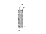
以下、かかる捲回電極体を備えたリチウムイオン二次電池の一実施形態につき、図1〜3に示す模式図を参照しつつ本発明をより具体的に説明するが、本発明の適用対象はかかる電池に限定されない。図示されるように、本実施形態に係るリチウムイオン二次電池100は、金属製(樹脂製またはラミネートフィルム製も好適である。)の筐体12を備えている。この筐体12の中には、長尺状の正極シート30、セパレータ50A、負極シート40およびセパレータ50Bをこの順に積層し次いで扁平形状に捲回して構築された捲回電極体20が収容される。
Hereinafter, the present invention will be described more specifically with reference to the schematic diagrams shown in FIGS. 1 to 3 with respect to an embodiment of a lithium ion secondary battery provided with such a wound electrode body. It is not limited to such a battery. As shown in the figure, the lithium ion
正極シート30は、例えば、正極合材を正極集電体32の少なくとも片面(好ましくは両面)に塗布乾燥して正極合材層35を形成することにより作製することができる。上記正極合材としては、正極活物質を、必要に応じて導電材、結着剤(バインダ)等とともに、適当な溶媒に分散させたペースト状またはスラリー状の組成物を使用することができる。
The
正極集電体32としては、導電性の良好な金属材料からなる導電性部材が用いられる。例えば、アルミニウムやアルミニウムを主成分とする合金を用いることができる。正極集電体の形状は、リチウムイオン二次電池の形状等に応じて異なり得るため、特に制限はなく、棒状、板状、シート状、箔状、メッシュ状等の種々の形態であり得る。本実施形態では、シート状の正極集電体が好適に採用され得る。
As the positive electrode
上記正極活物質は、リチウムを可逆的に吸蔵および放出可能な二相共存型化合物を主体とする。例えば、オリビン型化合物、リシコン型化合物等から選択される一種、または二種以上を含み得る。中でも、下記一般式(I):
LixFe1−yMyZO4 (I);
で表されるオリビン型化合物の使用が好ましい。上記式(I)中、Mは、Mn,Mg,Ni,Co,Cu,Zn,Ge,Cr,V,Nb,Mo,Ti,Gaから選択される少なくとも一種である。Zは、PまたはSiである。xは、0.05≦x≦1.2を満たす。また、yは、0≦y≦0.5を満たす。かかるオリビン型化合物の具体例としては、LiFePO4,Li2FeSiO4,LiFe0.5Mn0.5PO4,LiCo0.5Fe0.5PO4,LiNi0.5Fe0.5PO4等が挙げられる。特に好ましい例として、LiFePO4が挙げられる。また、リシコン型化合物としては、Li3Fe2(PO4)3,Li2ZnGeO4等が挙げられる。
これら二相共存型化合物としては、例えば、従来公知の方法で製造または提供されるものをそのまま使用することができる。例えば、平均粒径が0.2μm〜10μm程度の粉末状に調製されたものを好ましく使用することができる。
上記正極活物質に占める上記二相共存型化合物の配合量は、凡そ95質量%以上とする。この配合量は、好ましくは凡そ97質量%以上、より好ましくは凡そ98質量%以上とすることができる。
The positive electrode active material is mainly composed of a two-phase coexisting compound capable of reversibly occluding and releasing lithium. For example, it may contain one or more selected from olivine type compounds, lysicone type compounds and the like. Among these, the following general formula (I):
Li x Fe 1-y M y ZO 4 (I);
The use of an olivine type compound represented by In the above formula (I), M is at least one selected from Mn, Mg, Ni, Co, Cu, Zn, Ge, Cr, V, Nb, Mo, Ti, and Ga. Z is P or Si. x satisfies 0.05 ≦ x ≦ 1.2. Moreover, y satisfies 0 ≦ y ≦ 0.5. Specific examples of such olivine type compounds include LiFePO 4 , Li 2 FeSiO 4 , LiFe 0.5 Mn 0.5 PO 4 , LiCo 0.5 Fe 0.5 PO 4 , LiNi 0.5 Fe 0.5 PO 4. Etc. A particularly preferred example is LiFePO 4 . Examples of the silicon compound include Li 3 Fe 2 (PO 4 ) 3 and Li 2 ZnGeO 4 .
As these two-phase coexisting compounds, for example, those produced or provided by a conventionally known method can be used as they are. For example, those prepared in a powder form with an average particle size of about 0.2 μm to 10 μm can be preferably used.
The blending amount of the two-phase coexisting compound in the positive electrode active material is about 95% by mass or more. The blending amount is preferably about 97% by mass or more, more preferably about 98% by mass or more.
上記正極活物質は、上記二相共存型化合物に加えて、リチウムを可逆的に吸蔵および放出可能であり、且つ層状構造を有する各種リチウム遷移金属酸化物(層状Li酸化物)を一種または二種以上含む。かかる層状Li酸化物は、例えば、一般的なリチウムイオン二次電池の正極に用いられる層状構造の各種リチウム遷移金属酸化物であり得る。上記層状Li酸化物としては、その遷移金属として少なくともニッケルを含む酸化物(ニッケル含有リチウム複合酸化物)、少なくともコバルトを含む酸化物、少なくともマンガンを含む酸化物等が挙げられる。 The positive electrode active material is one or two kinds of various lithium transition metal oxides (layered Li oxides) capable of reversibly occluding and releasing lithium and having a layered structure in addition to the two-phase coexisting compound. Including above. Such a layered Li oxide may be, for example, various lithium transition metal oxides having a layered structure used for a positive electrode of a general lithium ion secondary battery. Examples of the layered Li oxide include an oxide containing at least nickel as its transition metal (nickel-containing lithium composite oxide), an oxide containing at least cobalt, and an oxide containing at least manganese.
層状構造のリチウム遷移金属酸化物の一好適例として、ニッケル含有リチウム複合酸化物(以下、層状LiNi酸化物ともいう。)が挙げられる。この層状LiNi酸化物は、LiおよびNi以外に、他の一種または二種以上の金属元素(すなわち、リチウムおよびニッケル以外の遷移金属元素および/または典型金属元素)を含むものであり得る。例えば、LiおよびNi以外に、Mn,Co,Mg,Alからなる群から選択される一種または二種以上を含むものであり得る。遷移金属元素のうちの主成分がNiであるか、あるいは遷移金属元素としてNiと他の一種または二種以上の遷移金属元素(例えば、MnおよびCo)とを概ね同程度の割合で含有するものが好ましい。特に好ましい層状LiNi酸化物として、下記一般式(II):
LiNi0.3+mMn0.3+nCo0.4−m−nO2 (II);
で表される酸化物が例示される。上記式(II)中、mは、0≦m≦0.4を、nは、0≦n≦0.4を満たす。好適例として、NiとMnとCoとを概ね同程度の割合で含む、LiNi1/3Mn1/3Co1/3O2等が挙げられる。
As a suitable example of the lithium transition metal oxide having a layered structure, a nickel-containing lithium composite oxide (hereinafter also referred to as a layered LiNi oxide) can be given. This layered LiNi oxide may contain one or more metal elements other than Li and Ni (that is, transition metal elements other than lithium and nickel and / or typical metal elements). For example, in addition to Li and Ni, it may contain one or more selected from the group consisting of Mn, Co, Mg, and Al. The main component of the transition metal element is Ni, or the transition metal element contains Ni and one or more other transition metal elements (for example, Mn and Co) in a substantially similar proportion. Is preferred. As a particularly preferred layered LiNi oxide, the following general formula (II):
LiNi 0.3 + m Mn 0.3 + n Co 0.4-mn O 2 (II);
The oxide represented by these is illustrated. In the above formula (II), m satisfies 0 ≦ m ≦ 0.4, and n satisfies 0 ≦ n ≦ 0.4. Preferable examples include LiNi 1/3 Mn 1/3 Co 1/3 O 2 that contains Ni, Mn, and Co at approximately the same ratio.
ここに開示されるリチウムイオン二次電池の正極に用いられる層状Li酸化物としては、平均粒径が2μm以下の粒子状のものを用いる。上記層状Li酸化物粒子の好ましい平均粒径は1.5μm以下であり、例えば1μm程度またはそれ以下のものを好ましく使用し得る。平均粒径の下限は特に限定されないが、通常は平均粒径0.1μm以上の層状Li酸化物粒子の使用が好ましい。
上記正極活物質に占める層状Li酸化物の配合量は、凡そ5質量%以下とする。この配合量は、3質量%以下が好ましく、2質量%以下がより好ましく、1質量%程度またはそれ以下であってもよい。多すぎると、正極活物質の主体として二相共存型化合物を用いることの利点が損なわれやすくなる。層状Li酸化物の配合量の下限は特に限定されないが、通常は、0.1質量%以上とすることが好ましい。配合量が少なすぎると、十分な電圧上昇緩和効果が発揮され難くなる。例えば、二相共存型化合物としてLiFePO4を、層状Li酸化物としてLiNi1/3Mn1/3Co1/3O2を用いる場合、その配合量を上記範囲から適宜選択することができる。
As the layered Li oxide used for the positive electrode of the lithium ion secondary battery disclosed herein, a particulate Li oxide having an average particle diameter of 2 μm or less is used. The average particle diameter of the layered Li oxide particles is preferably 1.5 μm or less, and for example, those having a particle size of about 1 μm or less can be preferably used. The lower limit of the average particle diameter is not particularly limited, but it is usually preferable to use layered Li oxide particles having an average particle diameter of 0.1 μm or more.
The amount of the layered Li oxide in the positive electrode active material is about 5% by mass or less. This amount is preferably 3% by mass or less, more preferably 2% by mass or less, and may be about 1% by mass or less. If the amount is too large, the advantage of using the two-phase coexisting compound as the main component of the positive electrode active material tends to be impaired. Although the minimum of the compounding quantity of layered Li oxide is not specifically limited, Usually, it is preferable to set it as 0.1 mass% or more. If the blending amount is too small, a sufficient voltage rise mitigating effect is hardly exhibited. For example, when LiFePO 4 is used as the two-phase coexisting compound and LiNi 1/3 Mn 1/3 Co 1/3 O 2 is used as the layered Li oxide, the blending amount can be appropriately selected from the above range.
好ましい一態様では、層状Li酸化物粒子の平均粒径および配合量を、後述する好ましいdV/d(SOC)を満たす電池が得られるように設定する。かかる構成によると、二相共存型化合物に加えて少量の層状Li酸化物粒子を用いることにより、充電末期の急激な電圧上昇を効果的に緩和することができる。これにより電池の耐久性が向上する。ここで、一般的なサイズ(典型的には10μm程度またはそれ以上)の層状Li酸化物粒子を使用する場合には、該層状Li酸化物粒子の使用量を多くすると、活物質として二相共存型化合物を用いることの利点(充放電時の電圧一定性、安全性向上等)が損なわれやすくなる。一方、層状Li酸化物粒子の使用量を少なくすると、電圧急上昇を緩和する効果が十分に発揮され難くなる。本発明の構成によると、平均粒径の小さな層状Li酸化物粒子を使用することにより、少量の添加によっても十分な電圧上昇緩和効果が得られる。したがって、正極活物質として二相共存型化合物を用いることの利点をよりよく活かしつつ、電池の耐久性を向上させることができる。 In a preferred embodiment, the average particle size and blending amount of the layered Li oxide particles are set so as to obtain a battery that satisfies the preferred dV / d (SOC) described later. According to such a configuration, by using a small amount of layered Li oxide particles in addition to the two-phase coexisting compound, a rapid voltage increase at the end of charging can be effectively mitigated. This improves the durability of the battery. Here, when layered Li oxide particles having a general size (typically about 10 μm or more) are used, if the amount of layered Li oxide particles used is increased, two-phase coexistence as an active material Advantages of using a mold compound (voltage stability during charge / discharge, improvement in safety, etc.) are likely to be impaired. On the other hand, if the amount of the layered Li oxide particles used is reduced, the effect of alleviating the voltage sudden rise is hardly exhibited. According to the configuration of the present invention, by using the layered Li oxide particles having a small average particle diameter, a sufficient voltage increase mitigating effect can be obtained even by adding a small amount. Therefore, the durability of the battery can be improved while better utilizing the advantages of using the two-phase coexisting compound as the positive electrode active material.
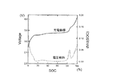
ここに開示されるリチウムイオン二次電池では、正極活物質として二相共存型化合物と層状Li酸化物粒子を含む構成により、充電時、電圧が充電後期半ば(例えば、SOC80%)程度から段階的かつ緩やかに上昇し、その充電曲線(SOCの変化に対する電圧の推移を示すグラフ)には、充電後期半ば程度から緩やかな電圧上昇を意味する「肩」(例えば、図4における充電曲線のSOC85%前後の部分)が現れる。更に詳しくは、ここに開示されるリチウムイオン二次電池は、充電後期において、上記充電曲線の微分値dV/d(SOC)(以下、電圧傾斜ともいう。)が0.125(単位は「V/%」である。他の箇所においても同じ。)以下(更には0.10以下)であるという特性を有し得る。かかる特性を有するリチウムイオン二次電池では、充電末期の電圧上昇が緩やかであることにより、容量劣化が抑制され得る。
In the lithium ion secondary battery disclosed herein, the voltage is gradually increased from the middle of the charge (for example,
ここに開示される技術は、他の側面として、リチウムを含有する二相共存型化合物を主体とする正極活物質を含む正極を備え;且つ、温度20℃にて0.2Cの定電流でSOC0%からSOC100%まで充電する電圧傾斜測定試験において、SOCの上昇に対する電圧変化を示す充電曲線の微分値dV/d(SOC)が、SOC50%〜100%の領域で0.125(V/%)以下となるように構築された、リチウムイオン二次電池;が含まれる。上記微分値は、0.10以下であることが好ましい。特に、充電末期(SOC100%近傍;例えば、SOC80%以上の領域)において、上記微分値が0.125以下(より好ましくは0.10以下)となるように構築されることが好ましい。かかる充電特性を有する二相共存型リチウムイオン二次電池は、充電末期の電圧急上昇が緩和されることにより、より優れた耐久性を有するものとなり得る。
The technology disclosed herein includes, as another aspect, a positive electrode including a positive electrode active material mainly composed of a two-phase coexisting compound containing lithium; and a SOC0 at a constant current of 0.2 C at a temperature of 20 ° C. In a voltage gradient measurement test for charging from% to
したがって、かかる特性を付与し得る技術の好適な適用対象として、層状Li酸化物粒子を含まない構成においては上記微分値が(典型的には、SOC100%近傍で)0.125を超えるような二相共存型リチウムイオン二次電池が挙げられる。かかる二次電池は、例えば、上述のような層状Li酸化物粒子を含む正極活物質構成を適用して、充電末期のdV/d(SOC)を引き下げることが特に有意義である。かかる構成の二相共存型リチウムイオン二次電池は、上記電圧傾斜測定試験において、電圧が充電後期半ば(例えば、SOC80%)程度から段階的かつ緩やかに上昇し、その充電曲線にかかる緩やかな電圧上昇を意味する「肩」(例えば、図4における充電曲線のSOC85%前後の部分)が現れる。これにより、充電後期(すなわち、SOC50%からSOC100%の領域)においても、上記微分値が0.125以下(好ましくは0.10以下)に抑えられた電池となり得る。
Therefore, as a suitable application target of the technology capable of imparting such characteristics, in a configuration not including the layered Li oxide particles, the differential value (typically in the vicinity of 100% SOC) exceeds 0.125. A phase coexistence type lithium ion secondary battery is mentioned. In such a secondary battery, for example, it is particularly meaningful to reduce the dV / d (SOC) at the end of charging by applying the positive electrode active material configuration including the layered Li oxide particles as described above. In the two-phase coexistence type lithium ion secondary battery having such a configuration, in the voltage gradient measurement test, the voltage gradually and gradually rises from about the middle of the charging (for example,
なお、充電末期の急激な電圧上昇を防いで電池を保護する手法として、例えば、電圧が所定上限値に到達した時点で充電を自動終了するような装置を併せて用いることも考えられる。しかし、かかるシステムが装備されている場合でも、二相共存型リチウムイオン二次電池のように充電末期の電圧上昇が急激すぎると、充電が自動終了しても、その直前の瞬間電圧傾斜が過大になり、部分的に過充電領域が発生するなどして、電池が著しく劣化する虞がある。したがって、かかるシステムと併せて二相共存型リチウムイオン二次電池を用いる場合であっても、充電末期の電圧上昇は緩やかであることが望ましい。 As a method for protecting the battery by preventing a rapid voltage increase at the end of charging, for example, it is conceivable to use a device that automatically ends charging when the voltage reaches a predetermined upper limit value. However, even when such a system is equipped, if the voltage rise at the end of charging is too rapid as in the case of a two-phase coexisting lithium-ion secondary battery, even if charging is automatically terminated, the instantaneous voltage gradient just before that is excessive. Thus, there is a possibility that the battery may be significantly deteriorated due to partial occurrence of an overcharge region. Therefore, even when a two-phase coexistence type lithium ion secondary battery is used in combination with such a system, it is desirable that the voltage increase at the end of charging is moderate.
また、かかる電池の保護システムを用いる場合、所定電圧値に到達して充電が自動終了する前により多くの電気を充電するためには、上記充電曲線に上述のような「肩」が現れるSOCレベルを可能な限り高くして(すなわち、SOC100%により近づけて)、電圧がほぼ平坦なまま(すなわち、電圧傾斜がほぼゼロの状態で)充電が進行するSOC領域をより長く継続させることが望ましい。例えば、平均粒径のより小さい(例えば、サブミクロンレベル(1μm未満))層状Li酸化物を用いることにより、電圧上昇緩和効果の効率が高まり、より少ない配合量(好ましくは1質量%未満、例えば0.4質量%程度)であっても優れた耐久性を実現し、且つ充電可能な電気量を増加させ得る。 Further, when using such a battery protection system, in order to charge more electricity before reaching a predetermined voltage value and automatically charging, the SOC level at which the “shoulder” as described above appears in the charging curve. Is as high as possible (ie, closer to 100% SOC), and it is desirable to continue the SOC region where charging proceeds for a longer time while the voltage is substantially flat (ie, with the voltage slope being substantially zero). For example, by using a layered Li oxide having a smaller average particle size (for example, submicron level (less than 1 μm)), the efficiency of the voltage rise mitigating effect is increased, and a smaller amount (preferably less than 1% by mass, for example, Even if it is about 0.4% by mass), excellent durability can be realized and the amount of electricity that can be charged can be increased.
上記正極合材に含まれ得る導電材としては、カーボン粉末やカーボンファイバー等の導電性粉末材料が好ましく用いられる。カーボン粉末としては、種々のカーボンブラック、例えば、アセチレンブラック、ファーネスブラック、ケッチェンブラック、グラファイト粉末等が好ましい。導電材は、一種のみを単独で、または二種以上を組み合わせて用いることができる。正極合材に含まれる導電材の量は、正極活物質の種類や量に応じて適宜選択すればよい。
導電材を使用する代わりに、あるいは導電材の使用と併せて、上記正極活物質の粒子表面に導電性を高める処理を施したものを用いてもよい。例えば、公知の方法により粒子表面に炭素被膜(炭素コーティング)を付与したものを好ましく使用し得る。
As the conductive material that can be included in the positive electrode mixture, conductive powder materials such as carbon powder and carbon fiber are preferably used. As the carbon powder, various carbon blacks such as acetylene black, furnace black, ketjen black, and graphite powder are preferable. A conductive material can be used alone or in combination of two or more. The amount of the conductive material contained in the positive electrode mixture may be appropriately selected according to the type and amount of the positive electrode active material.
Instead of using a conductive material, or in combination with the use of a conductive material, the positive electrode active material particle surface may be subjected to a treatment for enhancing conductivity. For example, a particle having a carbon film (carbon coating) applied to the particle surface by a known method can be preferably used.
上記結着剤(増粘剤としても把握され得る。)としては、例えば、水に溶解する水溶性ポリマーや、水に分散するポリマー、非水溶媒(有機溶媒)に溶解するポリマー等から適宜選択して用いることができる。また、一種のみを単独で用いてもよいし、二種以上を組み合わせて用いてもよい。 The binder (which may be grasped as a thickener) is appropriately selected from, for example, a water-soluble polymer that dissolves in water, a polymer that disperses in water, and a polymer that dissolves in a non-aqueous solvent (organic solvent). Can be used. Moreover, only 1 type may be used independently and 2 or more types may be used in combination.
水溶性ポリマーとしては、例えば、カルボキシメチルセルロース(CMC)、メチルセルロース(MC)、酢酸フタル酸セルロース(CAP)、ヒドロキシプロピルメチルセルロース(HPMC)、ヒドロキシプロピルメチルセルロースフタレート(HPMCP)、ポリビニルアルコール(PVA)等が挙げられる。 Examples of the water-soluble polymer include carboxymethylcellulose (CMC), methylcellulose (MC), cellulose acetate phthalate (CAP), hydroxypropylmethylcellulose (HPMC), hydroxypropylmethylcellulose phthalate (HPMCP), and polyvinyl alcohol (PVA). It is done.
水分散性ポリマーとしては、例えば、ポリテトラフルオロエチレン(PTFE)、テトラフルオロエチレン−パーフルオロアルキルビニルエーテル共重含体(PFA)、テトラフルオロエチレン−ヘキサフルオロプロピレン共重合体(FEP)、エチレン−テトラフルオロエチレン共重合体(ETFE)等のフッ素系樹脂、酢酸ビニル共重合体、スチレンブタジエンブロック共重合体(SBR)、アクリル酸変性SBR樹脂(SBR系ラテックス)、アラビアゴム等のゴム類等が挙げられる。 Examples of the water-dispersible polymer include polytetrafluoroethylene (PTFE), tetrafluoroethylene-perfluoroalkyl vinyl ether copolymer (PFA), tetrafluoroethylene-hexafluoropropylene copolymer (FEP), and ethylene-tetra. Fluorine resin such as fluoroethylene copolymer (ETFE), vinyl acetate copolymer, styrene butadiene block copolymer (SBR), acrylic acid-modified SBR resin (SBR latex), rubbers such as gum arabic, etc. It is done.
非水溶媒(有機溶媒)に溶解するポリマーとしては、例えば、ポリフッ化ビニリデン(PVDF)、ポリ塩化ビニリデン(PVDC)、ポリエチレンオキサイド(PEO)、ポリプロピレンオキサイド(PPO)、ポリエチレンオキサイド−プロピレンオキサイド共重合体(PEO−PPO)等が挙げられる。
結着剤の添加量は、正極活物質の種類や量に応じて適宜選択すればよい。
Examples of the polymer dissolved in the non-aqueous solvent (organic solvent) include, for example, polyvinylidene fluoride (PVDF), polyvinylidene chloride (PVDC), polyethylene oxide (PEO), polypropylene oxide (PPO), and polyethylene oxide-propylene oxide copolymer. (PEO-PPO) and the like.
What is necessary is just to select the addition amount of a binder suitably according to the kind and quantity of a positive electrode active material.
上記正極シート30とともに電極体20を構成する負極シート40は、例えば、負極合材を負極集電体42の少なくとも片面(好ましくは両面)に塗布乾燥して負極合材層45を形成することにより作製することができる。
上記負極合材としては、負極活物質を、必要に応じて一種または二種以上の結着剤(バインダ)等とともに、適当な溶媒に分散させたペースト状またはスラリー状の組成物が使用され得る。
The
As the negative electrode mixture, a paste-like or slurry-like composition in which a negative electrode active material is dispersed in an appropriate solvent together with one or two or more binders (binders) as required may be used. .
負極集電体42としては、導電性の良好な金属からなる導電性部材が好ましく用いられる。例えば、銅または銅を主成分とする合金を用いることができる。また、負極集電体42の形状は、リチウムイオン二次電池の形状等に応じて異なり得るため、特に制限はなく、棒状、板状、シート状、箔状、メッシュ状等の種々の形態であり得る。本実施形態ではシート状の銅製の負極集電体42が用いられ、捲回電極体20を備えるリチウムイオン二次電池100に好ましく使用され得る。
As the negative electrode
負極活物質としては、従来からリチウムイオン二次電池に用いられる物質の一種または二種以上を特に限定なく使用することができる。例えば、好適な負極活物質としてカーボン粒子が挙げられる。少なくとも一部にグラファイト構造(層状構造)を含む粒子状の炭素材料(カーボン粒子)が好ましく用いられる。いわゆる黒鉛質のもの(グラファイト)、難黒鉛化炭素質のもの(ハードカーボン)、易黒鉛化炭素質のもの(ソフトカーボン)、これらを組み合わせた構造を有するもののいずれの炭素材料も好適に使用され得る。中でも特に、天然黒鉛等の黒鉛粒子を好ましく使用することができる。 As the negative electrode active material, one type or two or more types of materials conventionally used in lithium ion secondary batteries can be used without any particular limitation. For example, a carbon particle is mentioned as a suitable negative electrode active material. A particulate carbon material (carbon particles) containing a graphite structure (layered structure) at least partially is preferably used. Any carbon material of a so-called graphitic material (graphite), non-graphitizable carbon material (hard carbon), easily graphitized carbon material (soft carbon), or a combination of these materials is preferably used. obtain. Among these, graphite particles such as natural graphite can be preferably used.
結着剤(増粘剤としても把握され得る。)には、上述の正極と同様のものを、一種のみを単独で、または二種以上を組み合わせて用いることができる。結着剤の添加量は、負極活物質の種類や量に応じて適宜選択すればよい。 As the binder (which can also be grasped as a thickener), the same positive electrode as that described above can be used alone or in combination of two or more. What is necessary is just to select the addition amount of a binder suitably according to the kind and quantity of a negative electrode active material.
また、正極シート30および負極シート40と重ね合わせて使用されるセパレータ50A,50Bとしては、例えば、ポリエチレン、ポリプロピレン等のポリオレフィン系樹脂から成る多孔質フィルムを好適に使用し得る。該フィルムは単層であってもよく多層であってもよい。二枚のセパレータ50A,50Bは、同一のものを使用してもよく、異なるものを使用してもよい。
Moreover, as
図2に示すように、正極シート30の長手方向に沿う第1の端部は正極合材層35が形成されておらず(または形成後除去されており)、正極集電体32が露出している。負極シート40についても同様に第1の端部は負極集電体42が露出している。正負極シート30,40をセパレータ50A,50Bとともに重ね合わせて積層体を形成する際には、正極シートの第1端部(正極集電体露出部)と負極シートの第1端部(負極集電体露出部)とが該積層体の長手方向の軸に対称に配置され、かつ両合材層35、45が重なり合うように、正負極シート30,40をややずらして重ね合わせる。この積層体を捲回し、次いで得られた捲回体を側面方向から押しつぶして拉げさせることによって扁平形状の捲回電極体20が得られる。
As shown in FIG. 2, the positive
得られた捲回電極体20を筐体12に収容するとともに(図3)、正極集電体32の露出部を外部接続用正極端子14に、負極集電体42の露出部を外部接続用負極端子16に、それぞれ電気的に接続する。この際、これら端子が筐体12の外部に一部配置されるようにする。そして、非水電解液を筐体12内に配置(注入)し、筐体12の開口部を当該筐体とそれに対応する蓋部材13との溶接等により封止して、リチウムイオン二次電池100の組み立てが完了する。なお、筐体12の封止や電解液の配置は、従来のリチウムイオン二次電池の製造で行われている手法と同様にして行うことができる。
The obtained
上記非水電解液は、適当な電解質を有機溶媒に溶解して調製することができる。電解質としては、一般的なリチウムイオン二次電池に用いられる電解質を特に制限なく使用することができる。例えば、LiPF6、LiBF4、LiClO4、LiAsF6、LiCF3SO3、LiC4F9SO3、LiN(CF3SO2)2、LiC(CF3SO2)3、LiI等から選択される一種または二種以上のリチウム塩を用いることができる。電解液中の電解質の濃度は特に制限されず、例えば従来のリチウムイオン二次電池に用いられる電解液の濃度と同等とすることができる。また、上記電解液には、上記電解質に加えて、各種添加剤等を加えてもよい。 The non-aqueous electrolyte can be prepared by dissolving a suitable electrolyte in an organic solvent. As the electrolyte, an electrolyte used for a general lithium ion secondary battery can be used without particular limitation. For example, selected from LiPF 6, LiBF 4, LiClO 4 , LiAsF 6, LiCF 3 SO 3, LiC 4 F 9 SO 3, LiN (CF 3 SO 2) 2, LiC (CF 3 SO 2) 3, LiI , etc. One or more lithium salts can be used. The concentration of the electrolyte in the electrolytic solution is not particularly limited, and can be, for example, equivalent to the concentration of the electrolytic solution used in a conventional lithium ion secondary battery. Moreover, you may add various additives etc. to the said electrolyte solution in addition to the said electrolyte.
また、上記非水電解液に用いられる有機溶媒(非水溶媒)としては、カーボネート類、エステル類、エーテル類、ニトリル類、スルホン類、ラクトン類等の非プロトン性溶媒を好ましく用いることができる。例えば、エチレンカーボネート(EC)、プロピレンカーボネート(PC)、ジエチルカーボネート(DEC)、ジメチルカーボネート(DMC)、エチルメチルカーボネート(EMC)、1,2−ジメトキシエタン(DME)、1,2−ジエトキシエタン、テトラヒドロフラン、2−メチルテトラヒドロフラン、ジオキサン、1,3−ジオキソラン、ジエチレングリコールジメチルエーテル、エチレングリコールジメチルエーテル、アセトニトリル、プロピオニトリル、ニトロメタン、N,N−ジメチルホルムアミド、ジメチルスルホキシド、スルホラン、γ−ブチロラクトン(BL)等の、一般にリチウムイオン二次電池に用いられる有機溶媒を、一種のみを単独で、あるいは二種以上を組み合わせて用いることができる。 In addition, as the organic solvent (nonaqueous solvent) used in the nonaqueous electrolytic solution, aprotic solvents such as carbonates, esters, ethers, nitriles, sulfones, and lactones can be preferably used. For example, ethylene carbonate (EC), propylene carbonate (PC), diethyl carbonate (DEC), dimethyl carbonate (DMC), ethyl methyl carbonate (EMC), 1,2-dimethoxyethane (DME), 1,2-diethoxyethane , Tetrahydrofuran, 2-methyltetrahydrofuran, dioxane, 1,3-dioxolane, diethylene glycol dimethyl ether, ethylene glycol dimethyl ether, acetonitrile, propionitrile, nitromethane, N, N-dimethylformamide, dimethyl sulfoxide, sulfolane, γ-butyrolactone (BL), etc. The organic solvents generally used for lithium ion secondary batteries can be used alone or in combination of two or more.
上述のように、二相共存型化合物は、結晶構造を維持したまま、リチウムイオンを含まない相(例えばFePO4)とリチウムイオンを含む相(例えばLiFePO4)との二相が安定して共存し得る。すなわち、二相共存型化合物の結晶内では、リチウムイオン含有相とリチウムイオン非含相との間でリチウムイオンの拡散がほとんど起こらず、リチウムイオンが拡散した中間相が存在しないことにより、充放電中の電位がほぼ一定に保たれ得る。したがって、車両や風力発電等、深度やレートが不規則な出入力が繰り返される用途にも、安定した電源となり得る。また、リチウムイオンのほとんどが放出されても結晶構造が壊れないため、理論容量と略同等の実効容量(可逆的に利用できる実際のリチウム量)を得ることができ、従来のリチウムイオン二次電池に匹敵する容量を得ることも可能である。したがって、二相共存型化合物を用いることによる安全性に加え、これらの特性からも、二相共存型リチウムイオン二次電池は、車両用電源として適したものとなり得る。 As described above, in the two-phase coexisting compound, the two phases of the phase not containing lithium ions (for example, FePO 4 ) and the phase containing lithium ions (for example, LiFePO 4 ) are stably coexisting while maintaining the crystal structure. Can do. In other words, in the crystal of the two-phase coexisting compound, there is almost no lithium ion diffusion between the lithium ion-containing phase and the lithium ion-free phase, and there is no intermediate phase in which lithium ions are diffused. The potential inside can be kept almost constant. Therefore, it can be a stable power source for applications such as vehicles and wind power generation where input and output with irregular depth and rate are repeated. In addition, even if most of the lithium ions are released, the crystal structure is not broken, so that the effective capacity (actual amount of lithium that can be used reversibly) is almost the same as the theoretical capacity. It is also possible to obtain a capacity comparable to Therefore, in addition to safety by using the two-phase coexisting compound, these characteristics can make the two-phase coexisting lithium ion secondary battery suitable as a power source for vehicles.
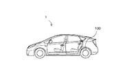
ここに開示される二相共存型リチウムイオン二次電池は、正極活物質として二相共存型化合物を用いたことによる上記特性に加え、正極活物質に層状Li酸化物が配合されていることから、更に、上述のように厳しい充放電サイクルにも対応し得る優れた耐久性を有し得る。そのため、自動車等の車両に搭載されるモータ(電動機)用電源として好適に使用され得る。かかる二次電池は、それらの複数個を直列および/または並列に接続してなる組電池の形態で使用されてもよい。したがって本発明は、図5に模式的に示すように、かかるリチウムイオン二次電池(組電池の形態であり得る。)100を電源として備える車両(典型的には自動車、特にハイブリッド自動車、電気自動車、燃料電池自動車のような電動機を備える自動車)1を提供する。 The two-phase coexistence type lithium ion secondary battery disclosed here has a layered Li oxide compounded in the positive electrode active material in addition to the above-mentioned characteristics due to the use of the two-phase coexistence type compound as the positive electrode active material. Furthermore, it can have excellent durability that can cope with severe charge / discharge cycles as described above. Therefore, it can be suitably used as a power source for a motor (electric motor) mounted on a vehicle such as an automobile. Such secondary batteries may be used in the form of an assembled battery formed by connecting a plurality of them in series and / or in parallel. Accordingly, as schematically shown in FIG. 5, the present invention provides a vehicle (typically an automobile, particularly a hybrid automobile, an electric automobile) provided with such a lithium ion secondary battery (which may be in the form of an assembled battery) 100 as a power source. An automobile equipped with an electric motor such as a fuel cell automobile) 1 is provided.
なお、本発明を実施する上で、ここに開示される二相共存型リチウムイオン二次電池において、車両用レベルの耐久試験でも電池性能が劣化し難くなる機構について解明する必要はないが、以下のようなことが考えられる。 In carrying out the present invention, in the two-phase coexistence type lithium ion secondary battery disclosed herein, it is not necessary to elucidate the mechanism that makes it difficult for the battery performance to deteriorate even in a vehicle-level durability test. It is conceivable that
二相共存型リチウムイオン二次電池は、上述のように、リチウムイオンが拡散した中間相が存在しないことで充電中の電位がほぼ一定に保たれ、また理論容量のほとんどが利用可能な半面、充電末期には正極中のリチウムイオンのほとんどが放出された状態になるため、電圧が急激に上昇して過充電状態に陥ることがある。車両用の耐久試験では、かかる過充電状態が生じる可能性がより高いため、著しい性能劣化(正極集電体の腐食や負極表面でのリチウム析出等)が起こり得る。
これに対し、正極活物質に層状Li酸化物を配合してなる二相共存型リチウムイオン二次電池では、二相共存型化合物と層状Li酸化物との充放電電位に差があり、前者の電位が後者の電位よりも低いため、電池全体では二段階の充放電電位を有することになる。このことにより、上述の充電曲線に「肩」が生じ、充電末期の電圧上昇が段階的かつ緩やかになる。換言すれば、上記層状Li酸化物中のリチウムイオンが、充電末期まで使用されないリザーバータンクとして確保されており、充電末期に二相共存型化合物のリチウムイオンが不足して電圧が上昇し始めると、そのリザーバータンクのリチウムイオンがリチウムイオン不足を補うようになる。また、層状Li酸化物では、リチウムイオンが拡散しながら充電が進むため、充電中の電位も徐々に上昇していく。これらのことから、充電末期における電圧上昇が段階的かつ緩やかになり、電極の過充電状態が抑制されて電池の劣化を低減することができる。
As described above, the two-phase coexistence type lithium ion secondary battery has an intermediate phase in which lithium ions are diffused, so that the potential during charging can be kept almost constant, and most of the theoretical capacity can be used. Since most of the lithium ions in the positive electrode are released at the end of charging, the voltage may rise rapidly and fall into an overcharged state. In an endurance test for a vehicle, such an overcharged state is more likely to occur, so that significant performance deterioration (corrosion of the positive electrode current collector, lithium deposition on the negative electrode surface, etc.) may occur.
On the other hand, in the two-phase coexistence type lithium ion secondary battery in which the positive electrode active material is mixed with the layered Li oxide, there is a difference in charge / discharge potential between the two-phase coexistence type compound and the layered Li oxide. Since the potential is lower than the latter potential, the entire battery has a two-stage charge / discharge potential. As a result, a “shoulder” occurs in the above-described charging curve, and the voltage increase at the end of charging becomes stepwise and gradual. In other words, the lithium ion in the layered Li oxide is secured as a reservoir tank that is not used until the end of charging, and when the voltage begins to increase due to the shortage of lithium ions of the two-phase coexisting compound at the end of charging, The lithium ions in the reservoir tank will compensate for the lack of lithium ions. In the layered Li oxide, charging proceeds while lithium ions are diffused, so that the potential during charging gradually increases. For these reasons, the voltage increase at the end of charging becomes gradual and gradual, the overcharged state of the electrode is suppressed, and the deterioration of the battery can be reduced.
また、上記層状Li酸化物の平均粒径をより小さくすると、その分布がより均一(緻密)になるため、正極合材層中のリチウムイオン不足をより均一かつ迅速に緩和することができる。したがって、同じ配合量であっても、平均粒径の違いによって、効果の程度に差が生じ得る。そして、平均粒径がより小さい層状Li酸化物を、より少ない配合量で用いることにより、十分な電圧上昇緩和効果(すなわち、容量劣化抑制効果)に加えて、電圧を一定に維持したまま充電可能な電気量をより多くする効果を得ることができる。 Further, when the average particle diameter of the layered Li oxide is made smaller, the distribution becomes more uniform (dense), so that the shortage of lithium ions in the positive electrode mixture layer can be alleviated more uniformly and rapidly. Therefore, even if the blending amount is the same, a difference in the degree of effect may occur due to a difference in average particle diameter. By using a layered Li oxide with a smaller average particle size in a smaller amount, charging can be performed while maintaining a constant voltage in addition to a sufficient voltage rise mitigating effect (ie, a capacity deterioration suppressing effect). An effect of increasing the amount of electricity can be obtained.
以下、本発明に関するいくつかの実施例を説明するが、本発明をかかる具体例に示すものに限定することを意図したものではない。 Several examples relating to the present invention will be described below, but the present invention is not intended to be limited to the specific examples.
<例1>
LiFePO4を、公知文献(Kaoru Dokkoら、Journal of Power Sources,vol.165,pp.656―659,2007)に従い、水熱合成法により合成した。得られたLiFePO4を、ボールミルを用いて平均粒径約0.7μmの粒子状に調製した。
次いで、特開2008−311067号公報に従い、得られた粒子状のLiFePO4の表面に炭素コーティングを付与した。すなわち、100質量部のLiFePO4に対して、5質量部のポリビニルアルコールを加えて水に分散させたスラリー状の組成物から、旋回流動層方式により、平均粒径20μmのLiFePO4―ポリビニルアルコール凝集体を得た。これを水素雰囲気下にて800℃で1.5時間焼成し、ポリビニルアルコールを還元、炭素化して炭素コート付LiFePO4を得た。
<Example 1>
LiFePO 4 was synthesized by a hydrothermal synthesis method according to a known literature (Kaoru Doko et al., Journal of Power Sources, vol. 165, pp. 656-659, 2007). The obtained LiFePO 4 was prepared into particles having an average particle diameter of about 0.7 μm using a ball mill.
Subsequently, according to JP 2008-311067 A, a carbon coating was applied to the surface of the obtained particulate LiFePO 4 . That is, from a slurry composition in which 5 parts by mass of polyvinyl alcohol was added to 100 parts by mass of LiFePO 4 and dispersed in water, LiFePO 4 -polyvinyl alcohol coagulated with an average particle size of 20 μm was obtained by a swirling fluidized bed method. A collection was obtained. This was baked at 800 ° C. for 1.5 hours in a hydrogen atmosphere, and polyvinyl alcohol was reduced and carbonized to obtain LiFePO 4 with carbon coating.
得られた炭素コート付LiFePO4(化合物A)に、LiFePO4:炭素コート:結着剤(PVDF)が質量比で88:2:10となるようにPVDFを加え、NMPを分散媒としてビーズミルにて均一に粉砕混練して、固形分(NV)が40質量%のスラリー状の正極合材を得た。この正極合材に対し、平均粒径1μmのLiNi1/3Mn1/3Co1/3O2(化合物B)を、化合物AとBとの質量比A:Bが90:10となるように添加し、よく混ぜ合わせた。
上記正極合材を、厚さ約15μm、10.0cm×100cmのアルミニウム箔(正極集電体)の両面に、塗布量(NV基準)が両面合わせて約30mg/m2となるように塗布した。これを乾燥した後、全体の厚みが約150μmとなるようにプレスして正極シートを得た。
To the obtained LiFePO 4 with carbon coat (compound A), PVDF was added so that the mass ratio of LiFePO 4 : carbon coat: binder (PVDF) was 88: 2: 10, and NMP was used as a dispersion medium in a bead mill. Then, the mixture was uniformly pulverized and kneaded to obtain a slurry-like positive electrode mixture having a solid content (NV) of 40% by mass. LiNi 1/3 Mn 1/3 Co 1/3 O 2 (compound B) having an average particle diameter of 1 μm is added to this positive electrode mixture so that the mass ratio A: B of compounds A and B is 90:10. And mixed well.
The positive electrode mixture was applied to both sides of an aluminum foil (positive electrode current collector) having a thickness of about 15 μm and 10.0 cm × 100 cm so that the coating amount (NV standard) was about 30 mg / m 2 on both sides. . After drying this, it was pressed to a total thickness of about 150 μm to obtain a positive electrode sheet.
負極合材として、天然黒鉛粉末とSBRとCMCとを、これら材料の質量比が95:2.5:2.5であり、かつNVが45質量%となるように、イオン交換水と混合してスラリー状組成物を調製した。この負極合材を、厚さ約12μm、10.5cm×100cmの銅箔(負極集電体)の両面に塗布した。これを乾燥した後、全体の厚みが100μmとなるようにプレスして負極シートを得た。 As a negative electrode mixture, natural graphite powder, SBR, and CMC are mixed with ion-exchanged water so that the mass ratio of these materials is 95: 2.5: 2.5 and NV is 45% by mass. A slurry composition was prepared. This negative electrode mixture was applied to both surfaces of a copper foil (negative electrode current collector) having a thickness of about 12 μm and 10.5 cm × 100 cm. After drying this, it pressed so that the whole thickness might be set to 100 micrometers, and obtained the negative electrode sheet.
得られた正極シートおよび負極シートを、厚さ20μmのポリプロピレン/ポリエチレン複合体多孔質シート二枚とともに重ね合わせて捲回し、得られた捲回電極体を正極端子および負極端子が取り出せる構造の内容積100mLの容器に電解液とともに収容し、該容器を封止して例1に係る電池を得た。電解液としては、ECとDMCとEMCとを1:1:1の体積比で混合した溶媒に、1mol/Lの濃度でLiPF6を溶解したものを用いた。
この電池に対し、コンディショニング処理として、1/5Cのレートで定電流充電を行い、次いで1/3Cのレートで4.1Vまで充電する操作と、1/3Cのレートで3.0Vまで放電させる操作とを3回繰り返し、例1に係る電池を得た。なお、ここで1Cとは、正極の理論容量より予測した電池容量(Ah)を1時間で充電できる電流量を意味する。
The obtained positive electrode sheet and negative electrode sheet are wound together with two 20 μm-thick polypropylene / polyethylene composite porous sheets and wound, and the obtained wound electrode body has an internal volume that allows the positive electrode terminal and the negative electrode terminal to be taken out. The battery according to Example 1 was obtained by accommodating the electrolyte solution in a 100 mL container and sealing the container. As the electrolytic solution, a solution obtained by dissolving LiPF 6 at a concentration of 1 mol / L in a solvent in which EC, DMC, and EMC were mixed at a volume ratio of 1: 1: 1 was used.
As a conditioning process, the battery is charged at a constant current rate of 1/5 C, then charged to 4.1 V at a rate of 1/3 C, and discharged to 3.0 V at a rate of 1/3 C. Were repeated three times to obtain a battery according to Example 1. Here, 1C means the amount of current that can charge the battery capacity (Ah) predicted from the theoretical capacity of the positive electrode in one hour.
<例2>
正極活物質として、化合物Aと化合物Bとの質量比を95:5としたこと以外は例1と同様にして、例2に係る電池を得た。
<例3>
正極活物質として、化合物Aと化合物Bとの質量比を97:3としたこと以外は例1と同様にして、例3に係る電池を得た。
<例4>
正極活物質として、化合物Aと化合物Bとの質量比を99:1としたこと以外は例1と同様にして、例4に係る電池を得た。
<例5>
平均粒径が10μmのLiNi1/3Mn1/3Co1/3O2を使用したこと以外は例1と同様にして、例5に係る電池を得た。
<例6>
平均粒径が10μmのLiNi1/3Mn1/3Co1/3O2を使用したこと以外は例2と同様にして、例6に係る電池を得た。
<Example 2>
A battery according to Example 2 was obtained in the same manner as Example 1 except that the mass ratio of Compound A and Compound B was 95: 5 as the positive electrode active material.
<Example 3>
A battery according to Example 3 was obtained in the same manner as in Example 1 except that the mass ratio of Compound A and Compound B was 97: 3 as the positive electrode active material.
<Example 4>
A battery according to Example 4 was obtained in the same manner as Example 1 except that the mass ratio of Compound A and Compound B was 99: 1 as the positive electrode active material.
<Example 5>
A battery according to Example 5 was obtained in the same manner as Example 1 except that LiNi 1/3 Mn 1/3 Co 1/3 O 2 having an average particle diameter of 10 μm was used.
<Example 6>
A battery according to Example 6 was obtained in the same manner as Example 2 except that LiNi 1/3 Mn 1/3 Co 1/3 O 2 having an average particle diameter of 10 μm was used.
<例7>
平均粒径が10μmのLiNi1/3Mn1/3Co1/3O2を使用したこと以外は例3と同様にして、例7に係る電池を得た。
<例8>
平均粒径が10μmのLiNi1/3Mn1/3Co1/3O2を使用したこと以外は例4と同様にして、例8に係る電池を得た。
<例9>
LiFePO4のみを使用した(すなわち、LiNi1/3Mn1/3Co1/3O2を使用しなかった)こと以外は例1と同様にして、例9に係る電池を得た。
<Example 7>
A battery according to Example 7 was obtained in the same manner as Example 3 except that LiNi 1/3 Mn 1/3 Co 1/3 O 2 having an average particle diameter of 10 μm was used.
<Example 8>
A battery according to Example 8 was obtained in the same manner as Example 4 except that LiNi 1/3 Mn 1/3 Co 1/3 O 2 having an average particle diameter of 10 μm was used.
<Example 9>
A battery according to Example 9 was obtained in the same manner as Example 1 except that only LiFePO 4 was used (that is, LiNi 1/3 Mn 1/3 Co 1/3 O 2 was not used).
[電圧傾斜測定試験]
例5および例9の電池をSOC0%の状態に調製し、温度20℃にて、0.2CのレートでSOC0%からSOC100%となるまで充電する操作を行い、その間の電圧値の変化(充電曲線)を記録し、その充電曲線の微分値dV/d(SOC)を電圧傾斜として算出した。これらの電池について、充電曲線および電圧傾斜をプロットしたグラフを、それぞれ図4、図5に示す。
[Voltage slope measurement test]
The batteries of Examples 5 and 9 were prepared in a state of
[充放電サイクル試験]
各電池に対し、60℃において、端子間電圧が4.1Vとなるまで2Cで充電する操作と、4.1Vから2.5Vまで2Cで放電させる操作とを1充放電サイクルとして、これを1000サイクル繰り返した。
[Charge / discharge cycle test]
For each battery, an operation of charging at 2C until the voltage between the terminals reaches 4.1 V at 60 ° C. and an operation of discharging at 2 C from 4.1 V to 2.5 V are defined as one charge / discharge cycle. The cycle was repeated.
[容量維持率]
各電池につき、上記サイクル試験前後において、SOC(State of Charge)100%の状態に調製したのち、温度25℃にて、SOC0%となるまで0.2Cのレートで放電させ、このときの放電容量を測定した。容量維持率(%)を、耐久試験後の放電容量に対する耐久試験前の放電容量の百分率として求めた。
また、容量維持率の向上比として、層状Li酸化物を使用しなかった例9の電池の容量維持率(82%)と例4の電池(平均粒径10μm;配合量1質量%)の容量維持率(82.5%)との差(0.5%)を基準値1とし、当該基準値に対する各電池の容量維持率向上分の比を、容量維持率向上比として算出した。
[Capacity maintenance rate]
Before and after the cycle test, each battery was prepared in a state of SOC (State of Charge) 100%, and then discharged at a temperature of 25 ° C. at a rate of 0.2 C until SOC reached 0%. Was measured. The capacity retention rate (%) was determined as a percentage of the discharge capacity before the endurance test with respect to the discharge capacity after the endurance test.
Further, as the capacity retention ratio improvement ratio, the capacity retention ratio (82%) of the battery of Example 9 in which no layered Li oxide was used and the capacity of the battery of Example 4 (average particle size 10 μm; blending amount 1 mass%). The difference (0.5%) from the maintenance rate (82.5%) was set as the reference value 1, and the ratio of the capacity maintenance rate improvement of each battery to the reference value was calculated as the capacity maintenance rate improvement ratio.
例1〜9の電池について、これらの結果を、各電池における層状Li酸化物の平均粒径(μm)および正極活物質の総量に対する配合比率(質量%)とともに表1に示す。 About the battery of Examples 1-9, these results are shown in Table 1 with the average particle diameter (micrometer) of the layered Li oxide in each battery, and the mixture ratio (mass%) with respect to the total amount of a positive electrode active material.

表1に示されるように、正極活物質として二相共存型化合物(ここではLiFePO4)および層状Li酸化物(ここではLiNi1/3Mn1/3Co1/3O2)を用いてなる例1〜8の電池は、例9の電池と比べ、いずれも充放電サイクル試験後の容量維持率が向上した。中でも、平均粒径が1μmの層状Li酸化物を用いてなる例1〜4の電池は、平均粒径が10μmの層状Li酸化物を用いてなる例5〜8の電池と比べ、容量維持率の向上比が約3〜7倍高かった。詳しくは、配合量が1質量%のものでは、平均粒径が1μmの場合(例4)は、平均粒径が10μmの場合(例8)と比べ、7倍の向上比を示した。同様に、平均粒径が1μmの場合と平均粒径が10μmの場合とを向上比で比べた場合、配合量3質量%では前者(例3)が後者(例7)の5倍、配合量5質量%では前者(例2)が後者(例6)の3倍、配合量1質量%では前者(例1)が後者(例5)の略3倍と、より高い容量劣化抑制効果を示した。例えば、平均粒径が1μmの層状Li酸化物を用いた場合、わずか1質量%の配合量で、平均粒径が10μmの層状Li酸化物を5質量%配合した場合に勝る高容量維持率が得られた。
また、図5に示されるように、正極活物質として二相共存型化合物のみを用いてなる例9の電池は、充電末期に、電圧傾斜が0.125を超える急激な電圧上昇が起こった。これに対し、図4から明らかなように、層状Li酸化物を用いてなる例5の電池は、充電曲線がSOC80%を超える時点まで平坦に維持され、充電末期近く(ここでは、SOC80〜100%の領域)において、電圧傾斜が0.125以下(ここでは凡そ0.075以下)という緩やかな電圧上昇を示した。また、平均粒径1μmの層状Li酸化物を例5の電池の1/10の配合量で用いた例4の電池では、上記充電曲線の平坦部分が更に長く(すなわち、よりSOC100%に近い領域まで)継続し、一定電圧で充電できる電気量がさらに増加し得る。
As shown in Table 1, a two-phase coexisting compound (here, LiFePO 4 ) and a layered Li oxide (here, LiNi 1/3 Mn 1/3 Co 1/3 O 2 ) are used as the positive electrode active material. As compared with the battery of Example 9, the batteries of Examples 1 to 8 all improved the capacity retention rate after the charge / discharge cycle test. Among them, the batteries of Examples 1 to 4 using the layered Li oxide having an average particle diameter of 1 μm have a capacity retention rate as compared with the batteries of Examples 5 to 8 using the layered Li oxide having an average particle diameter of 10 μm. The improvement ratio was about 3 to 7 times higher. Specifically, when the blending amount is 1% by mass, when the average particle size is 1 μm (Example 4), the improvement ratio is 7 times that when the average particle size is 10 μm (Example 8). Similarly, when the average particle diameter is 1 μm and the average particle diameter is 10 μm, the former (Example 3) is five times the latter (Example 7) and the blending amount is 3% by mass. At 5% by mass, the former (Example 2) is three times the latter (Example 6), and at 1% by mass, the former (Example 1) is about three times the latter (Example 5), showing a higher capacity deterioration suppressing effect. It was. For example, when a layered Li oxide having an average particle diameter of 1 μm is used, the high capacity retention rate is superior to that when a layered Li oxide having an average particle diameter of 10 μm is blended with only 1% by mass and 5% by mass. Obtained.
Further, as shown in FIG. 5, the battery of Example 9 using only the two-phase coexisting compound as the positive electrode active material experienced a rapid voltage increase with a voltage gradient exceeding 0.125 at the end of charging. On the other hand, as is clear from FIG. 4, the battery of Example 5 using the layered Li oxide is kept flat until the charging curve exceeds 80% SOC, and near the end of charging (here,
以上、本発明の具体例を詳細に説明したが、これらは例示にすぎず、請求の範囲を限定するものではない。請求の範囲に記載の技術には、以上に例示した具体例を様々に変形、変更したものが含まれる。 As mentioned above, although the specific example of this invention was demonstrated in detail, these are only illustrations and do not limit a claim. The technology described in the claims includes various modifications and changes of the specific examples illustrated above.
1 車両(自動車)
20 捲回電極体
30 正極シート(正極)
32 正極集電体
35 正極合材層
40 負極シート(負極)
42 負極集電体
45 負極合材層
50A,50B セパレータ
100 リチウムイオン二次電池
1 Vehicle (Automobile)
20
32 Positive electrode
42 Anode
Claims (5)
前記正極活物質は、リチウムを含有する二相共存型化合物を95質量%以上含み、層状構造のリチウム遷移金属酸化物からなる粒子を0.1〜5質量%の割合で更に含有し、
ここで、前記層状リチウム遷移金属酸化物粒子は、平均粒径が0.1μm〜2μmである、リチウムイオン二次電池。 A lithium ion secondary battery comprising: an electrode body having a positive electrode containing a positive electrode active material and a negative electrode containing a negative electrode active material; and a non-aqueous electrolyte containing a lithium salt in an organic solvent,
The positive electrode active material contains 95% by mass or more of a two-phase coexisting compound containing lithium, and further contains particles composed of a lithium transition metal oxide having a layered structure in a proportion of 0.1 to 5% by mass ,
Here, the layered lithium transition metal oxide particles have an average particle size of 0.1 m to 2 [mu] m, the lithium ion secondary battery.
LixFe1−yMyZO4 (I)
(ここで、Mは、Mn,Mg,Ni,Co,Cu,Zn,Ge,Cr,V,Nb,Mo,Ti,Gaからなる群から選択される少なくとも一種であり;Zは、PまたはSiであり;xは、0.05≦x≦1.2を満たし;yは、0≦y≦0.5を満たす。);
で表されるオリビン型化合物である、請求項1に記載のリチウムイオン二次電池。 The two-phase coexisting compound has the following general formula (I):
Li x Fe 1- y My ZO 4 (I)
(Here, M is at least one selected from the group consisting of Mn, Mg, Ni, Co, Cu, Zn, Ge, Cr, V, Nb, Mo, Ti, and Ga; Z is P or Si X satisfies 0.05 ≦ x ≦ 1.2; y satisfies 0 ≦ y ≦ 0.5);
The lithium ion secondary battery of Claim 1 which is an olivine type compound represented by these.
LiNi0.3+mMn0.3+nCo0.4−m−nO2 (II)
(ここで、mは、0≦m≦0.4を満たし;nは、0≦n≦0.4を満たす。);
で表される組成を有する、請求項1〜3のいずれか一項に記載のリチウムイオン二次電池。 The layered lithium transition metal oxide particles have the following general formula (II):
LiNi 0.3 + m Mn 0.3 + n Co 0.4-mn O 2 (II)
(Where m satisfies 0 ≦ m ≦ 0.4; n satisfies 0 ≦ n ≦ 0.4);
The lithium ion secondary battery as described in any one of Claims 1-3 which has a composition represented by these.
Priority Applications (5)
| Application Number | Priority Date | Filing Date | Title |
|---|---|---|---|
| JP2009236469A JP5081886B2 (en) | 2009-10-13 | 2009-10-13 | Non-aqueous electrolyte type lithium ion secondary battery |
| US13/501,102 US9209462B2 (en) | 2009-10-13 | 2010-09-14 | Non-aqueous electrolyte solution type lithium ion secondary battery |
| CN2010800453410A CN102696138A (en) | 2009-10-13 | 2010-09-14 | Nonaqueous electrolyte solution type lithium ion secondary battery |
| PCT/JP2010/065832 WO2011046000A1 (en) | 2009-10-13 | 2010-09-14 | Nonaqueous electrolyte solution type lithium ion secondary battery |
| KR1020127012229A KR101477873B1 (en) | 2009-10-13 | 2010-09-14 | Nonaqueous electrolyte solution type lithium ion secondary battery |
Applications Claiming Priority (1)
| Application Number | Priority Date | Filing Date | Title |
|---|---|---|---|
| JP2009236469A JP5081886B2 (en) | 2009-10-13 | 2009-10-13 | Non-aqueous electrolyte type lithium ion secondary battery |
Publications (3)
| Publication Number | Publication Date |
|---|---|
| JP2011086405A JP2011086405A (en) | 2011-04-28 |
| JP2011086405A5 JP2011086405A5 (en) | 2012-08-16 |
| JP5081886B2 true JP5081886B2 (en) | 2012-11-28 |
Family
ID=43876054
Family Applications (1)
| Application Number | Title | Priority Date | Filing Date |
|---|---|---|---|
| JP2009236469A Active JP5081886B2 (en) | 2009-10-13 | 2009-10-13 | Non-aqueous electrolyte type lithium ion secondary battery |
Country Status (5)
| Country | Link |
|---|---|
| US (1) | US9209462B2 (en) |
| JP (1) | JP5081886B2 (en) |
| KR (1) | KR101477873B1 (en) |
| CN (1) | CN102696138A (en) |
| WO (1) | WO2011046000A1 (en) |
Cited By (1)
| Publication number | Priority date | Publication date | Assignee | Title |
|---|---|---|---|---|
| WO2022209815A1 (en) | 2021-04-01 | 2022-10-06 | 株式会社Gsユアサ | Positive electrode active material for nonaqueous electrolyte power storage elements, positive electrode for nonaqueous electrolyte power storage elements, nonaqueous electrolyte power storage element, power storage unit, and power storage device |
Families Citing this family (18)
| Publication number | Priority date | Publication date | Assignee | Title |
|---|---|---|---|---|
| US20120231341A1 (en) * | 2011-03-09 | 2012-09-13 | Jun-Sik Kim | Positive active material, and electrode and lithium battery containing the positive active material |
| JP5553798B2 (en) * | 2011-06-10 | 2014-07-16 | 株式会社日立製作所 | Positive electrode material for lithium ion secondary battery |
| KR101965016B1 (en) * | 2011-07-25 | 2019-04-02 | 에이일이삼 시스템즈, 엘엘씨 | Blended cathode materials |
| JP6047871B2 (en) * | 2011-10-20 | 2016-12-21 | Tdk株式会社 | Battery pack and power storage device using the same |
| JP6065901B2 (en) * | 2012-02-29 | 2017-01-25 | 日立化成株式会社 | Lithium ion battery |
| KR101560862B1 (en) * | 2012-08-02 | 2015-10-15 | 주식회사 엘지화학 | Positive-electrode active material with improved output property, and lithium secondary battery comprising the same |
| KR101738280B1 (en) * | 2012-09-04 | 2017-05-19 | 도요타지도샤가부시키가이샤 | Nonaqueous electrolyte secondary battery |
| JP6080044B2 (en) * | 2013-01-21 | 2017-02-15 | パナソニックIpマネジメント株式会社 | Nonaqueous secondary battery plate manufacturing method |
| JP6213122B2 (en) * | 2013-10-07 | 2017-10-18 | 株式会社デンソー | Battery pack |
| CN103825021B (en) * | 2014-03-12 | 2016-02-17 | 石哲文 | A kind of preparation method of rare earth doped compound lithium cobaltate cathode material |
| JP6160602B2 (en) * | 2014-03-24 | 2017-07-12 | 株式会社デンソー | Lithium ion secondary battery |
| JP6007942B2 (en) * | 2014-05-19 | 2016-10-19 | トヨタ自動車株式会社 | Non-aqueous electrolyte secondary battery and manufacturing method thereof |
| JP6237546B2 (en) | 2014-09-11 | 2017-11-29 | トヨタ自動車株式会社 | Nonaqueous electrolyte secondary battery |
| WO2016147572A1 (en) * | 2015-03-13 | 2016-09-22 | パナソニックIpマネジメント株式会社 | Cell management device and power supply device |
| DE102016217373A1 (en) * | 2016-09-13 | 2018-03-15 | Robert Bosch Gmbh | Process for the preparation of a homogeneous particulate material composition |
| KR102336723B1 (en) * | 2017-12-27 | 2021-12-06 | 주식회사 엘지에너지솔루션 | Apparatus and method for managing battery |
| CN109817927B (en) * | 2019-01-25 | 2022-03-25 | 安徽益佳通电池有限公司 | Lithium battery positive electrode material capable of improving SOC estimation precision and preparation method thereof |
| JP7211900B2 (en) * | 2019-06-06 | 2023-01-24 | トヨタ自動車株式会社 | Positive electrode material for secondary battery, and secondary battery using the same |
Family Cites Families (12)
| Publication number | Priority date | Publication date | Assignee | Title |
|---|---|---|---|---|
| JP4843848B2 (en) * | 2001-01-22 | 2011-12-21 | 株式会社デンソー | Non-aqueous electrolyte secondary battery |
| JP2005044722A (en) * | 2003-07-25 | 2005-02-17 | Nichia Chem Ind Ltd | Cathode active substance for nonaqueous electrolyte solution secondary battery and nonaqueous electrolyte solution secondary battery |
| JP4999292B2 (en) | 2004-07-21 | 2012-08-15 | 三洋電機株式会社 | Non-aqueous electrolyte battery |
| JP2007250299A (en) * | 2006-03-15 | 2007-09-27 | Hitachi Vehicle Energy Ltd | Nonaqueous electrolyte solution secondary battery |
| JP5137312B2 (en) * | 2006-03-17 | 2013-02-06 | 三洋電機株式会社 | Non-aqueous electrolyte battery |
| JP2007317534A (en) * | 2006-05-26 | 2007-12-06 | Sony Corp | Non-aqueous electrolyte secondary battery |
| JP5250948B2 (en) | 2006-07-28 | 2013-07-31 | 株式会社Gsユアサ | Nonaqueous electrolyte secondary battery |
| JP5156406B2 (en) * | 2007-01-18 | 2013-03-06 | 日立マクセルエナジー株式会社 | Positive electrode for lithium secondary battery, method for producing the same, and lithium secondary battery |
| JP5153156B2 (en) | 2007-02-13 | 2013-02-27 | 三洋電機株式会社 | Method for producing positive electrode for non-aqueous electrolyte secondary battery |
| JP5176400B2 (en) | 2007-06-14 | 2013-04-03 | 住友大阪セメント株式会社 | Manufacturing method of electrode material, electrode material, electrode and battery |
| CN101299470A (en) | 2008-05-16 | 2008-11-05 | 东莞新能源科技有限公司 | Lithium ion battery |
| US9184446B2 (en) | 2009-10-13 | 2015-11-10 | Toyota Jidosha Kabushiki Kaisha | Non-aqueous electrolyte lithium ion secondary battery |
-
2009
- 2009-10-13 JP JP2009236469A patent/JP5081886B2/en active Active
-
2010
- 2010-09-14 WO PCT/JP2010/065832 patent/WO2011046000A1/en active Application Filing
- 2010-09-14 KR KR1020127012229A patent/KR101477873B1/en active IP Right Grant
- 2010-09-14 US US13/501,102 patent/US9209462B2/en active Active
- 2010-09-14 CN CN2010800453410A patent/CN102696138A/en active Pending
Cited By (1)
| Publication number | Priority date | Publication date | Assignee | Title |
|---|---|---|---|---|
| WO2022209815A1 (en) | 2021-04-01 | 2022-10-06 | 株式会社Gsユアサ | Positive electrode active material for nonaqueous electrolyte power storage elements, positive electrode for nonaqueous electrolyte power storage elements, nonaqueous electrolyte power storage element, power storage unit, and power storage device |
Also Published As
| Publication number | Publication date |
|---|---|
| KR101477873B1 (en) | 2014-12-30 |
| US20130059199A1 (en) | 2013-03-07 |
| US9209462B2 (en) | 2015-12-08 |
| KR20120093953A (en) | 2012-08-23 |
| JP2011086405A (en) | 2011-04-28 |
| CN102696138A (en) | 2012-09-26 |
| WO2011046000A1 (en) | 2011-04-21 |
Similar Documents
| Publication | Publication Date | Title |
|---|---|---|
| JP5081886B2 (en) | Non-aqueous electrolyte type lithium ion secondary battery | |
| JP6098878B2 (en) | Non-aqueous electrolyte secondary battery | |
| JP5709024B2 (en) | Nonaqueous electrolyte secondary battery and current collector for secondary battery | |
| JP5797993B2 (en) | Nonaqueous electrolyte secondary battery | |
| JP5392585B2 (en) | Non-aqueous electrolyte type lithium ion secondary battery | |
| JP6086248B2 (en) | Non-aqueous electrolyte secondary battery | |
| JP2018116856A (en) | Positive electrode active material for lithium ion secondary battery | |
| JP2010211990A (en) | Charge and discharge control method of lithium ion secondary battery, secondary battery system, and hybrid automobile | |
| JP5279567B2 (en) | Nonaqueous electrolyte secondary battery | |
| KR101572405B1 (en) | Lithium secondary battery | |
| JP6902206B2 (en) | Lithium ion secondary battery | |
| JP6988169B2 (en) | A method for manufacturing a negative electrode for a non-aqueous electrolyte secondary battery, and a method for manufacturing a non-aqueous electrolyte secondary battery. | |
| WO2011074083A1 (en) | Lithium ion secondary battery | |
| WO2022138451A1 (en) | Electrode, nonaqueous electrolyte battery, and battery pack | |
| JP6493766B2 (en) | Lithium ion secondary battery | |
| JP6120101B2 (en) | Non-aqueous electrolyte secondary battery and manufacturing method thereof | |
| JP2023034701A (en) | Positive electrode active material and nonaqueous electrolyte secondary battery including the same | |
| JP2021077531A (en) | Non-aqueous electrolyte secondary battery | |
| JP6120068B2 (en) | Method for producing non-aqueous electrolyte secondary battery | |
| JP7288479B2 (en) | Non-aqueous electrolyte secondary battery | |
| JP2023091566A (en) | Positive electrode and nonaqueous electrolyte secondary battery using the same | |
| JP2014116217A (en) | Lithium ion secondary battery cathode and lithium ion secondary battery | |
| JP2011181234A (en) | Nonaqueous electrolyte type lithium ion secondary battery | |
| JP2012089418A (en) | Negative active material for lithium ion secondary battery, lithium ion secondary battery using the same, and manufacturing method of negative active material for lithium ion secondary battery |
Legal Events
| Date | Code | Title | Description |
|---|---|---|---|
| A521 | Request for written amendment filed |
Free format text: JAPANESE INTERMEDIATE CODE: A523 Effective date: 20120704 |
|
| A621 | Written request for application examination |
Free format text: JAPANESE INTERMEDIATE CODE: A621 Effective date: 20120704 |
|
| A871 | Explanation of circumstances concerning accelerated examination |
Free format text: JAPANESE INTERMEDIATE CODE: A871 Effective date: 20120704 |
|
| A975 | Report on accelerated examination |
Free format text: JAPANESE INTERMEDIATE CODE: A971005 Effective date: 20120727 |
|
| TRDD | Decision of grant or rejection written | ||
| A01 | Written decision to grant a patent or to grant a registration (utility model) |
Free format text: JAPANESE INTERMEDIATE CODE: A01 Effective date: 20120809 |
|
| A01 | Written decision to grant a patent or to grant a registration (utility model) |
Free format text: JAPANESE INTERMEDIATE CODE: A01 |
|
| A61 | First payment of annual fees (during grant procedure) |
Free format text: JAPANESE INTERMEDIATE CODE: A61 Effective date: 20120903 |
|
| FPAY | Renewal fee payment (event date is renewal date of database) |
Free format text: PAYMENT UNTIL: 20150907 Year of fee payment: 3 |
|
| R151 | Written notification of patent or utility model registration |
Ref document number: 5081886 Country of ref document: JP Free format text: JAPANESE INTERMEDIATE CODE: R151 |
|
| FPAY | Renewal fee payment (event date is renewal date of database) |
Free format text: PAYMENT UNTIL: 20150907 Year of fee payment: 3 |
|
| R250 | Receipt of annual fees |
Free format text: JAPANESE INTERMEDIATE CODE: R250 |
|
| R250 | Receipt of annual fees |
Free format text: JAPANESE INTERMEDIATE CODE: R250 |
|
| R250 | Receipt of annual fees |
Free format text: JAPANESE INTERMEDIATE CODE: R250 |
|
| R250 | Receipt of annual fees |
Free format text: JAPANESE INTERMEDIATE CODE: R250 |
|
| R250 | Receipt of annual fees |
Free format text: JAPANESE INTERMEDIATE CODE: R250 |
|
| R250 | Receipt of annual fees |
Free format text: JAPANESE INTERMEDIATE CODE: R250 |
|
| R250 | Receipt of annual fees |
Free format text: JAPANESE INTERMEDIATE CODE: R250 |
|
| R250 | Receipt of annual fees |
Free format text: JAPANESE INTERMEDIATE CODE: R250 |
|
| R250 | Receipt of annual fees |
Free format text: JAPANESE INTERMEDIATE CODE: R250 |