JP5081069B2 - Semiconductor memory device - Google Patents
Semiconductor memory device Download PDFInfo
- Publication number
- JP5081069B2 JP5081069B2 JP2008150276A JP2008150276A JP5081069B2 JP 5081069 B2 JP5081069 B2 JP 5081069B2 JP 2008150276 A JP2008150276 A JP 2008150276A JP 2008150276 A JP2008150276 A JP 2008150276A JP 5081069 B2 JP5081069 B2 JP 5081069B2
- Authority
- JP
- Japan
- Prior art keywords
- film
- data
- memory cell
- voltage
- semiconductor
- Prior art date
- Legal status (The legal status is an assumption and is not a legal conclusion. Google has not performed a legal analysis and makes no representation as to the accuracy of the status listed.)
- Expired - Fee Related
Links
Images
Classifications
-
- G—PHYSICS
- G11—INFORMATION STORAGE
- G11C—STATIC STORES
- G11C11/00—Digital stores characterised by the use of particular electric or magnetic storage elements; Storage elements therefor
- G11C11/56—Digital stores characterised by the use of particular electric or magnetic storage elements; Storage elements therefor using storage elements with more than two stable states represented by steps, e.g. of voltage, current, phase, frequency
- G11C11/5657—Digital stores characterised by the use of particular electric or magnetic storage elements; Storage elements therefor using storage elements with more than two stable states represented by steps, e.g. of voltage, current, phase, frequency using ferroelectric storage elements
Landscapes
- Engineering & Computer Science (AREA)
- Computer Hardware Design (AREA)
- Semiconductor Memories (AREA)
- Non-Volatile Memory (AREA)
Description
本発明は、強誘電体膜の残留分極により半導体層のチャネル抵抗を変調する半導体記憶装置に関し、特に、3値以上の多値データを記憶することのできる半導体記憶装置に関する。 The present invention relates to a semiconductor memory device that modulates channel resistance of a semiconductor layer by residual polarization of a ferroelectric film, and more particularly to a semiconductor memory device that can store multi-value data of three or more values.
強誘電体を用いた不揮発性メモリには、大きく分けてキャパシタ型と、ゲート絶縁膜を強誘電体膜で構成した電界効果トランジスタ(Field Effect Transistor、FET)型との2種類がある。 There are two types of nonvolatile memories using ferroelectrics: a capacitor type and a field effect transistor (FET) type in which a gate insulating film is formed of a ferroelectric film.
キャパシタ型は、ダイナミック・ランダム・アクセス・メモリ(DRAM)と類似した構造であり、強誘電体キャパシタに電荷を保持し、強誘電体の分極方向によって、情報の0、1を区別する。強誘電体キャパシタに蓄積された分極は、その上下に配置された電極に誘起される電荷と結合しており、電圧を切断した状態で消失しない。しかし、情報を読み出す際に、記憶していた分極を破壊し、情報を失ってしまうため、この方式においては情報の再書き込み動作が必要となる。そのため、読み出し動作毎に行われる再書き込みに伴って分極反転が繰り返され、分極の疲労劣化が問題となる。また、この構造では分極電荷をセンスアンプで読み出すため、センスアンプの検知限界以上の電荷量(典型的には100fC)が必要である。強誘電体は面積あたりの分極電荷が材料固有であり、メモリセルを微細化する場合であっても、同じ材料を使う限り電極面積は一定の大きさが必要である。従って、プロセスルールの微細化に比例縮小してキャパシタサイズを小さくすることは困難であり、大容量化に不適である。 The capacitor type has a structure similar to that of a dynamic random access memory (DRAM), holds charges in a ferroelectric capacitor, and distinguishes 0 and 1 of information depending on the polarization direction of the ferroelectric. The polarization accumulated in the ferroelectric capacitor is combined with the charges induced in the electrodes arranged above and below it, and does not disappear when the voltage is cut off. However, when the information is read out, the stored polarization is destroyed and the information is lost. In this method, an information rewriting operation is required. For this reason, the polarization inversion is repeated with the rewriting performed every reading operation, and the fatigue deterioration of the polarization becomes a problem. In this structure, since the polarization charge is read by the sense amplifier, a charge amount (typically 100 fC) that is greater than the detection limit of the sense amplifier is required. A ferroelectric has a polarization charge per area inherent to the material, and even when the memory cell is miniaturized, the electrode area needs to have a certain size as long as the same material is used. Therefore, it is difficult to reduce the capacitor size in proportion to the miniaturization of the process rule, which is not suitable for increasing the capacity.
これに対して、FET型の強誘電体メモリは、強誘電体膜の分極の向きによって変化するチャネルの導通状態を検出することにより情報を読み出すため、非破壊での情報の読み出しが可能である。また、FETの増幅作用によって出力電圧振幅を大きくすることができ、スケーリング則に依存した微細化が可能である。従来、チャネルとなるシリコン基板上にゲート絶縁膜となる強誘電体膜を形成したFET型トランジスタが提案されている。この構造は、Metal-Ferroelectric-Semiconductor(MFS)型FET(以下、「MFSFET」という。)と呼ばれている。 On the other hand, since the FET type ferroelectric memory reads information by detecting the conduction state of the channel that changes depending on the polarization direction of the ferroelectric film, it can read information nondestructively. . Further, the output voltage amplitude can be increased by the amplification action of the FET, and miniaturization depending on the scaling law is possible. Conventionally, an FET transistor has been proposed in which a ferroelectric film serving as a gate insulating film is formed on a silicon substrate serving as a channel. This structure is called a Metal-Ferroelectric-Semiconductor (MFS) type FET (hereinafter referred to as “MFSFET”).
ところで、MFSFETからなるメモリセルには、通常、強誘電体膜の分極の向きに応じた2値データが記憶されるが、1メモリセルに多値データを記憶する方式のMFSFETが、特許文献1に提案されている。 By the way, normally, binary data corresponding to the polarization direction of the ferroelectric film is stored in a memory cell made of MFSFET, but an MFSFET of a type that stores multi-value data in one memory cell is disclosed in Patent Document 1. Has been proposed.
この方式によれば、強誘電体膜を、チャネル領域の両側に位置する2つの領域と、この2つの領域の中間に位置する領域とに分け、各3つの領域の分極強誘電体膜の分極の向きを独立に制御することによって、1メモリセルに多値(3ビット8値)データを記憶させることができる。また、記憶された多値データに対応したMFSFETの閾値の変化を検出することによって、多値データを読み出すことができる。これにより、MFSFETからなる強誘電体メモリの記憶容量を飛躍的に増大させることが可能となる。
しかしながら、上記のMFSFETに記憶された多値データは、ドレイン電流の大きさによって判定されるが、3ビット8値の多値データに対応するドレイン電流は、2ビット4値しか取り得ない。そのため、実際には、ドレイン電流の向きを変えたドレイン電流の大きさの測定を2回行い、それらの組合せによって、MFSFETに記憶された多値データを判定する必要があり、読み出し動作が複雑になるという問題がある。 However, although the multi-value data stored in the MFSFET is determined by the magnitude of the drain current, the drain current corresponding to the 3-bit 8-value multi-value data can take only 2 bits and 4 values. Therefore, in practice, it is necessary to measure the magnitude of the drain current by changing the direction of the drain current twice, and to determine the multi-value data stored in the MFSFET by the combination thereof, which makes the read operation complicated. There is a problem of becoming.
本発明は、かかる課題に鑑みなされたもので、その主な目的は、簡単な動作で、MFSFETに記憶された多値データを読み出すことのできる半導体記憶装置を提供することにある。 The present invention has been made in view of such problems, and a main object thereof is to provide a semiconductor memory device capable of reading out multi-value data stored in an MFSFET with a simple operation.
本発明に係わる半導体記憶装置は、強誘電体膜からなるゲート絶縁膜と、半導体膜からなるチャネルとを有する第1の電界効果トランジスタで構成されたメモリセルと、メモリセルに直列に接続された読み出し用の負荷素子とを備え、メモリセルは、強誘電体膜の分極状態に応じた、少なくとも3値以上のチャネル抵抗値を多値データとして記憶しており、メモリセルに記憶された多値データは、メモリセルと負荷素子との間の中間電位を検出することによって読み出され、読み出し動作は、メモリセルに記憶された多値データを、チャネル抵抗値の高い状態から順に判別することによって実行されることを特徴とする。 A semiconductor memory device according to the present invention includes a memory cell formed of a first field effect transistor having a gate insulating film made of a ferroelectric film and a channel made of a semiconductor film, and connected in series to the memory cell. A load element for reading, and the memory cell stores at least three or more channel resistance values according to the polarization state of the ferroelectric film as multi-value data, and the multi-value stored in the memory cell Data is read by detecting an intermediate potential between the memory cell and the load element, and the read operation is performed by sequentially determining the multi-value data stored in the memory cell from the state with the highest channel resistance value. It is executed.
このような構成により、簡単な方法で、かつ、低いチャネル抵抗値が記憶されたデータを破壊することなく、メモリセルに記憶された多値データを読み出すことができる。 With such a configuration, it is possible to read out the multi-value data stored in the memory cell by a simple method and without destroying the data in which the low channel resistance value is stored.
ある好適な実施形態において、上記読み出し動作は、負荷素子の抵抗値を、チャネル抵抗値に応じて、チャネル抵抗値の高い状態から順に変化させながら実行される。これにより、n値のデータに対して、抵抗値の異なるn−1個の負荷抵抗を用意することなく、1個の負荷抵抗で読み出し動作を実行することができ、半導体記憶装置のチップサイズを縮小することができる。 In a preferred embodiment, the read operation is executed while changing the resistance value of the load element in order from the highest channel resistance value according to the channel resistance value. As a result, a read operation can be executed with one load resistor without preparing n-1 load resistors having different resistance values for n-value data, and the chip size of the semiconductor memory device can be reduced. Can be reduced.
ここで、上記負荷素子は、第2の電界効果トランジスタで構成されており、読み出し動作は、第2の電界効果トランジスタのゲート電極に印加する電圧を変化させることによって、負荷素子の抵抗値を変化させながら実行されることが好ましい。さらに、第2の電界効果トランジスタのチャネルは、第1の電界効果トランジスタのチャネルと共通の半導体膜からなることが好ましい。これにより、読み出し用の負荷素子を、メモリセルを構成するMFSFETと同程度の素子サイズにすることができ、半導体記憶装置のチップサイズをより縮小することができる。 Here, the load element is composed of a second field effect transistor, and the read operation changes the resistance value of the load element by changing the voltage applied to the gate electrode of the second field effect transistor. It is preferable to be executed. Further, the channel of the second field effect transistor is preferably made of a semiconductor film common to the channel of the first field effect transistor. As a result, the read load element can have the same element size as the MFSFET constituting the memory cell, and the chip size of the semiconductor memory device can be further reduced.
また、上記メモリセルは、複数配列されており、読み出し動作において、多値データが判別されたメモリセルは、メモリセルの通電が遮断されることが好ましい。これにより、データ判別後のメモリセルに記憶されたデータを破壊することなく、全てのメモリセルに記憶された多値データを読み出すことができる。 In addition, it is preferable that a plurality of the memory cells are arranged, and that the memory cells in which the multi-value data is determined in the read operation are cut off from energization of the memory cells. Thereby, the multi-value data stored in all the memory cells can be read without destroying the data stored in the memory cells after the data determination.
また、上記読み出し動作において、強誘電体膜に印加される電圧は、強誘電体膜の分極状態を変化させない値に設定されることが好ましい。これにより、メモリセルに記憶されたデータを破壊することなく、メモリセルに記憶された多値データを読み出すことができる。 In the read operation, the voltage applied to the ferroelectric film is preferably set to a value that does not change the polarization state of the ferroelectric film. Thereby, the multi-value data stored in the memory cell can be read without destroying the data stored in the memory cell.
本発明によれば、MFSFETからなるメモリセルに記憶された多値データを、簡単な方法で、かつ、記憶されたデータを破壊することなく読み出すことができ、大容量記憶が可能な半導体記憶装置を提供することができる。 According to the present invention, a multi-value data stored in a memory cell made of MFSFET can be read out by a simple method without destroying the stored data, and can be stored in a large capacity. Can be provided.
本願出願人は、選択スイッチング素子を備えたMFSFETからなるメモリセルであって、セルサイズを小さくすることが可能な新規な半導体メモリセルの構成を、特願2007−103754号の出願明細書に開示している。 The applicant of the present application discloses a configuration of a novel semiconductor memory cell, which is a memory cell composed of an MFSFET having a selection switching element and can reduce the cell size, in the application specification of Japanese Patent Application No. 2007-103754. doing.
図1は、本願出願人が上記出願明細書で開示した半導体メモリセルの構成を説明した図で、(a)は断面図、(b)は等価回路図である。 1A and 1B are diagrams illustrating a configuration of a semiconductor memory cell disclosed by the applicant of the present application in the above application specification, in which FIG. 1A is a cross-sectional view and FIG. 1B is an equivalent circuit diagram.
図1(a)に示すように、基板11上に、強誘電体膜13と常誘電体膜16とが、半導体膜14を介して積層されて形成されており、強誘電体膜13側には、メモリ素子を構成するMFSFET21のゲート電極12が形成され、常誘電体膜16側には、選択スイッチング素子を構成するMISFET22、23のゲート電極17a、17bが形成されている。また、半導体膜14は、MFSFET21及びMISFET22、23に共通のチャネルを構成しており、半導体膜14上には、MFSFET21及びMISFET22、23に共通のソース電極15a及びドレイン電極15bが形成されている。
As shown in FIG. 1A, a
このような構成により、メモリ素子をなすMFSFET21のゲート電極12と、選択スイッチング素子をなすMISFET22、23のゲート電極17a、17bとを、平面的に近接して配置できるため、セルサイズを小さくすることができる。
With such a configuration, the
メモリ素子21へのデータの書き込みは、図2(a)、(b)に示すように、ゲート電極17aに電圧を印加して、MISFET22をオンさせた状態で、ドレイン電極15b及びゲート電極12間に電圧を印加することによって、強誘電体膜13に垂直方向の電界を発生させ、これにより、強誘電体膜13の分極状態を変化させることによって行われる。
As shown in FIGS. 2A and 2B, data is written into the
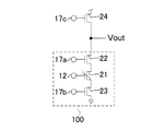
また、メモリ素子21に書き込まれたデータの読み出しは、図3に示すように、ゲート電極17a、17bに電圧を印加して、MISFET22、23をオンさせた状態で、ドレイン電極15b、ソース電極15a間に電圧を印加し、強誘電体膜13の分極状態に応じてチャネル導電率の変化を、メモリ素子21と負荷素子24との間の中間電位Voutを検出することによって行われる。
In addition, as shown in FIG. 3, the data written in the
本発明における半導体記憶装置は、メモリ素子21に、強誘電体膜の分極状態に応じた、少なくとも3値以上のチャネル抵抗値を多値データとして記憶させるようにしたものである。
In the semiconductor memory device of the present invention, at least three channel resistance values corresponding to the polarization state of the ferroelectric film are stored in the
以下に、本発明の実施の形態について、図面を参照しながら説明する。以下の図面においては、説明の簡略化のため、実質的に同一の機能を有する構成要素を同一の参照符号で示す。なお、本発明は以下の実施形態に限定されない。 Embodiments of the present invention will be described below with reference to the drawings. In the following drawings, components having substantially the same function are denoted by the same reference numerals for the sake of simplicity. In addition, this invention is not limited to the following embodiment.
図4は、本実施形態における半導体記憶装置の基本的な構成を示した図で、(a)は断面図、(b)はその等価回路図である。 4A and 4B are diagrams showing a basic configuration of the semiconductor memory device according to the present embodiment, in which FIG. 4A is a cross-sectional view and FIG. 4B is an equivalent circuit diagram thereof.
図4(a)に示すように、基板11上に、強誘電体膜13と常誘電体膜16とが、半導体膜14を介して積層されて形成されており、強誘電体膜13側には、メモリ素子を構成するMFSFET(第1の電界効果トランジスタ)21のゲート電極12が形成され、常誘電体膜16側には、選択スイッチング素子を構成するMISFET22、23のゲート電極17a、17bが形成されている。
As shown in FIG. 4A, the
ここで、半導体膜14は、MFSFET21及びMISFET22、23、24に共通のチャネルを構成しており、半導体膜14上には、MFSFET21及びMISFET22、23に共通のソース電極15a及びドレイン電極15bが形成されている。
Here, the
また、常誘電体膜16側には、読み出し用の負荷素子を構成するMISFET(第2の電界効果トランジスタ)24のゲート電極17cが形成され、半導体膜14上には、MISFET24のソース・ドレイン電極15e、15fが形成されている。ここで、MISFET24のチャネルは、MFSFET21及びMISFET22、23のチャネルを構成する半導体膜14と同じ半導体膜14で構成されている。
A
本実施形態における半導体記憶装置の具体的な構成を以下に説明する。 A specific configuration of the semiconductor memory device according to the present embodiment will be described below.
図4(a)に示すように、単結晶チタン酸ストロンチウム(SrTiO3、以下STO)からなる基板11の(100)面上に、厚さ30nmのルテニウム酸ストロンチウム(SrRuO3、以下SRO)膜からなるゲート電極12が形成されている。
As shown in FIG. 4A, a strontium ruthenate (SrRuO 3 , hereinafter referred to as SRO) film having a thickness of 30 nm is formed on the (100) surface of a
また、基板11上には、厚さ450nmのジルコニウム酸チタン酸鉛(Pb(Zr,Ti)O3、以下PZT)膜からなるゲート絶縁膜を構成する強誘電体膜13と、厚さ30nmのn型の酸化物半導体である酸化亜鉛(ZnO)膜からなるチャネルを構成する半導体膜14が積層されている。
On the
半導体膜14上には、厚さ20nmのチタン(Ti)膜と、厚さ30nmの白金(Pt)膜の積層膜からなるソース・ドレイン電極15b〜15fが形成されている。このとき、電極15cは、ゲート電極12に対するソース電極と、ゲート電極17aに対するドレイン電極を兼ねている。また、電極15dは、ゲート電極12に対するドレイン電極と、ゲート電極17bに対するソース電極を兼ねている。
On the
半導体膜14上には、厚さ100nmの窒化珪素(SiN)膜からなるゲート絶縁膜を構成する常誘電体膜16が形成され、常誘電体膜16上には、厚さ30nmのTi層と厚さ17nmのPt膜の積層膜からなる第2のゲート電極17a、17b及び第3のゲート電極17cが形成されている。
A
常誘電体膜16上には、二酸化シリコン(SiO2)膜からなる層間絶縁膜18が形成されている。さらに、層間絶縁膜18及び常誘電体膜16中には、ソース・ドレイン電極15b、15b、15e、15fに接続されたタングステンプラグ19が形成され、層間絶縁膜18上には、タングステンプラグ19間を接続するアルミニウム配線20が形成されている。ここで、メモリセルのドレイン電極15bと負荷素子のソース電極15eとは、タングステンプラグ19及びアルミニウム配線20を介して電気的に接続されている。
On the
なお、ソース・ドレイン電極15b、15cはゲート電極17aと、ソース・ドレイン電極15c、15dはゲート電極12と、ソース・ドレイン電極15d、15bはゲート電極17bと、ソース・ドレイン電極15e、15fはゲート電極17cと、それぞれ平面的に重なる部分を有することが望ましい。
The source /
次に、本実施形態における半導体記憶装置の基本的な動作を説明する。 Next, the basic operation of the semiconductor memory device in this embodiment will be described.
まず、MFSFET21のゲート絶縁膜として使用するPZT膜13の分極特性について説明する。厚さ450nmのPZT膜13の両面に、SRO膜及びTi膜からなる電極をそれぞれ形成し、PZT膜13に印加した電界に対して、得られた残留分極密度2Prを測定した。その結果、電極間に3V以上の電圧を印加したとき、分極は反転し、±10Vの電圧を印加した後、電圧を0Vに戻したときに得られる分極密度2Prは、60μC/cm2であった。
First, the polarization characteristics of the
また、PZT膜13上に、厚さ30nmのZnO膜14を形成し、ZnO膜14のキャリア濃度をホール測定により求めたところ、2×1015cm−3であった。ZnO膜14の厚さは30nmであるから、単位面積あたりのキャリア密度は6×109cm−2なる。これに、素電荷量1.6×10⁻¹⁹Cを乗じて求められる電荷密度は、9.6×10⁻⁴μC/cm2であり、上述のPZT膜13の分極電荷密度よりも小さい。従って、PZT膜13の分極が下向きのとき、この分極に反発してZnO膜14中のキャリアが追い払われ、チャネルは空乏化する。一方、PZT膜13の分極が上向きのとき、分極密度に対応した密度のキャリアが、PZT膜13とZnO膜14の界面に誘起される。
Further, a
次に、PZT膜13の分極によるZnO膜14のキャリア濃度変調を利用したチャネル導電率変調について説明する。MFSFET21の第1のゲート電極12に負電圧を印加したとき、PZT膜13の分極は下を向き、ZnO膜14は空乏化するので、チャネル導電率は低くなる。すなわち、オフ状態となる。一方、ゲート電極12に正電圧を印加したとき、PZT膜13の分極は上を向き、キャリア濃度が高くなるので、チャネル導電率は高くなる。すなわちオン状態となる。このように、ゲート電極12に印加する電圧によって、チャネル(ZnO膜)14の導電状態を制御できる。しかも、ゲート電極12に印加する電圧を除去した状態でも、PZT膜13の分極は残留するので、導電状態は維持される。
Next, channel conductivity modulation using carrier concentration modulation of the
これを確認するため、MFSFET21のサブスレッショルド特性を調べた。
In order to confirm this, the subthreshold characteristic of the
図5(a)に示すように、ソース電極15cを接地し、ドレイン電極15dに0.1Vの電圧を印加した状態で、ゲート電極12の電圧を掃引して、ドレイン電流IDSを測定した。
As shown in FIG. 5A, the drain current IDS was measured by sweeping the voltage of the
図5(b)は、ゲート電圧VGSを−10Vから+10Vに掃引したときのドレイン電流IDSをプロットしたグラフである。ドレイン電流にヒステリシスが観測され、ゲート電圧を−10Vから掃引したときにゲート電圧0Vで流れるドレイン電流は1pA以下と小さく、10Vから掃引したときにゲート電圧0Vで流れるドレイン電流(図中のa点)は1μA以上と大きい。これは、上述のように、負電圧印加でチャネル14が空乏化して高抵抗に、正電圧印加で電荷蓄積状態となって低抵抗となるからである。
FIG. 5B is a graph plotting the drain current I DS when the gate voltage V GS is swept from −10V to + 10V. Hysteresis is observed in the drain current, and when the gate voltage is swept from −10V, the drain current flowing at 0V is as small as 1 pA or less, and when the gate voltage is swept from 10V, the drain current flowing at 0V (point a in the figure) ) Is as large as 1 μA or more. This is because, as described above, the
さらに、ゲート電極12に、例えば、−1.5V、−2.0V、−5.0Vを印加した後に、ゲート電圧0Vで流れるドレイン電流は、−10Vから掃引したときにゲート電圧0Vで流れるドレイン電流と、10Vから掃引したときにゲート電圧0Vで流れるドレイン電流との中間値(図中のb点、c点、d点)をとる。すなわち、ゲート電圧0Vで流れるドレイン電流の大きさに応じて多値データに対応させることによって、メモリセルに多値データを記憶させることが可能となる。
Furthermore, after applying, for example, −1.5 V, −2.0 V, and −5.0 V to the
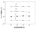
しかも、電圧を切断した状態であっても、PZT膜13の残留分極は保存されるため、電荷蓄積状態は維持される。実際、図6に示すように、図5(b)中の点a〜dに対応した多値データを記憶させたMFSFET21を室温下で104秒間放置した後でも、点a〜dに対応したドレイン電流IDSの比は維持される。
Moreover, even if the voltage is cut off, the residual polarization of the
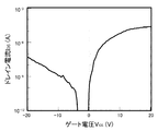
図7は、選択スイッチング素子として用いるMISFET22、23のサブスレッショルド特性を調べた結果である。なお、ゲート絶縁膜である常誘電体膜16には、膜厚100nmのSiN膜を用いた。
FIG. 7 shows the results of examining the subthreshold characteristics of
次に、再び図4(a)を参照しながら、本実施形態における半導体記憶装置の動作を説明する。 Next, the operation of the semiconductor memory device according to the present embodiment will be described with reference to FIG. 4A again.
非アクセス状態では、MFSFET21のゲート電極12、及びMISFET22、23のゲート電極17a、17bを接地する。ゲート電極17a、17bを接地することによって、2つのMISFET22、23はオフとなっており、ソース、ドレイン電極15a、15bに任意の電圧を印加しても、MFSFET21に誤書き込みは生じない。
In the non-access state, the
データの書き込み動作では、まず、ゲート電極17a、17bに正電圧(例えば10V)を印加してMISFET22、23をオンさせた状態で、ソース電極15a、ドレイン電極15b及びゲート電極12に電圧を印加し、ソース電極15aとゲート電極12間、及びドレイン電極15bとゲート電極12間に、強誘電体膜13の分極がすべて上を向くような電圧を印加することによって、リセット動作を行う。
In the data write operation, first, a voltage is applied to the
次いで、ゲート電極17a、17bに正電圧(例えば10V)を印加して、MISFET22、23をオンさせた状態で、ソース電極15a、ドレイン電極15b、及びゲート電極12に所定の電圧を印加する。これにより、ゲート絶縁膜(強誘電体膜)13上のチャネル(半導体膜)14とゲート電極12の間に垂直方向の電界が印加される。
Next, a predetermined voltage is applied to the
例えば、“0”、”1”、”2”、”3”の4値のデータの書き込みは、次のようにして行うことができる。 For example, four-value data “0”, “1”, “2”, “3” can be written as follows.
データ”0”を書き込む場合、ゲート電極12を接地し、ソース、ドレイン電極15a、15bに正電圧(例えば3.5v)を印加する。また、データ”1”を書き込む場合、ゲート電極12を接地し、ソース、ドレイン電極15a、15b、に、データ”0”を書き込むときよりも小さい正電圧(例えば2.5V)を印加する。同様に、データ”2”を書き込む場合、ゲート電極12を接地し、ソース、ドレイン電極15a、15bに、データ”1”を書き込むときよりも小さい正電圧(例えば1.5V)を印加する。また、データ”3”を書き込む場合、ゲート電極12を接地し、ソース、ドレイン電極15a、15bに、データ”2”を書き込むときよりも小さい正電圧(例えば0V)を印加する。これにより、ゲート絶縁膜(強誘電体膜)13に、大きさの異なる分極量が蓄積される。なお、この場合、上向きの分極量は、”3”>”2”>”1”>”0”となる。
When data “0” is written, the
次に、“0”、”1”、”2”、”3”の4値のデータの読み出しは、次のようにして行うことができる。 Next, four-value data “0”, “1”, “2”, “3” can be read as follows.
図5(b)に示した点a〜dのドレイン電流特性を有するMFSFET21は、ゲート長(L)が1μm、ゲート幅(W)が100μmであり、読み出し電圧が0.1Vであるために、単位長さ(W/L=1)あたりのチャネル抵抗値は、それぞれ約1MΩ(データ”3”)、約100MΩ(データ”2”)、約10GΩ(データ”1”)、約1TΩ(データ”0”)となる。これに接続する選択スイッチング素子22、23は、図5に示したサブスレッショルド特性を有し、このMISFETは、ゲート長(L)が2μm、ゲート幅(W)が8μmであり、読み出し電圧は0.1Vであるために、単位長さ(W/L=1)あたりの抵抗値は、オン状態で約40kΩである。
The
また、メモリセルに接続された負荷素子も、選択スイッチング素子と同一の構成を有するMISFET24で構成されているため、その抵抗値は、オン状態の40kΩからオフ状態の約1TΩまで、ゲート電極17cの印加電圧の大きさにより可変である。それ故、読み出し時に、負荷素子におけるゲート電極17cに所定の電圧を印加して、負荷素子の抵抗値を、上記の各チャネル抵抗値の間に設定することによって、メモリセルと負荷素子との間の中間電位を読み出すことで、4値のデータを判別することができる。
Further, since the load element connected to the memory cell is also composed of the
しかしながら、チャネル抵抗値の小さなデータが記憶されているとき、負荷素子の抵抗値が小さく設定されて読み出しが行われると、メモリ素子に大きな電圧が印加されて、データがディスターブされるおそれがある。それ故、データの読み出しは、チャネル抵抗値の高い状態から順に判別することが望ましい。 However, when data with a small channel resistance value is stored, if the resistance value of the load element is set to a small value and reading is performed, a large voltage may be applied to the memory element to disturb the data. Therefore, it is desirable to read data in order from the highest channel resistance value.
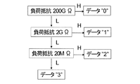
すなわち、図8に示すように、最初に、データが”0”であるか否かを判定する。この時に、データが”0”以外と判定された場合には、次のステップに進み、データが”1”であるか否かを判定する。この時に、データが”1”以外と判定された場合には、次のステップに進み、データが”2”であるか否かを判定する。そして、データが”2”以外と判定された場合には、データが”3”であると判定する。このとき、負荷素子の抵抗値も、ステップ毎に小さくしていく。 That is, as shown in FIG. 8, it is first determined whether or not the data is “0”. At this time, if it is determined that the data is other than “0”, the process proceeds to the next step to determine whether or not the data is “1”. At this time, if it is determined that the data is other than “1”, the process proceeds to the next step to determine whether or not the data is “2”. When it is determined that the data is other than “2”, it is determined that the data is “3”. At this time, the resistance value of the load element is also decreased for each step.
電源電圧を1.8Vにした場合の具体的なステップを、図9(a)、(b)を参照しながら説明する。メモリ素子21に書き込まれたデータの読み出しは、図9(a)に示すように、ゲート電極17a、17bに電圧を印加して、MISFET22、23をオンさせた状態で、ソース・ドレイン電極間に電圧を印加し、強誘電体膜13の分極状態に応じてチャネル導電率の変化を、メモリ素子21と負荷素子24との間の中間電位(出力電圧)Voutを検出することによって行われる。図9(b)は、負荷素子24の抵抗値を変えて、メモリ素子21に記憶されたデータを読み出したときの中間電位Voutと、メモリ素子21のソース側及びドレイン側に加わる電圧Vs、Vdを表にしたものである。
Specific steps when the power supply voltage is 1.8 V will be described with reference to FIGS. 9 (a) and 9 (b). As shown in FIG. 9A, the data written in the
最初に、チャネル抵抗値の高い状態に対応したデータ”0”を読み出すために、負荷素子24の抵抗値を200G(2×10¹¹)Ωとする。この値は、データ”0”のチャネル抵抗値(1×10¹²)Ωの1/5である。このとき、図9(b)の表に示すように、出力電圧Voutは、データ”0”の場合には、1.50Vとなり、それ以外のデータ”1”、”2”及び”3”の場合には、0.09V以下となる。すなわち、1.50Vが出力されたときは、メモリ素子21に記憶されたデータは、”0”であると判定される。
First, in order to read out data “0” corresponding to a high channel resistance value, the resistance value of the
次に、出力電圧Voutが、0.09V以下の場合、すなわち、記憶されたデータが”0”でないと判定した場合には、負荷素子24の抵抗値を2G(2×10⁹)Ωに下げる。なお、この値は、データ”1”のチャネル抵抗値(1×10¹⁰)Ωの1/5である。このとき、出力電圧Voutは、データ”1”の場合には、1.50Vとなり、それ以外のデータ”2”及び”3”の場合には、0.09V以下となる。すなわち、1.50Vが出力されたときは、メモリ素子21に記憶されたデータは、”1”であると判定される。
Next, when the output voltage Vout is 0.09 V or less, that is, when it is determined that the stored data is not “0”, the resistance value of the
次に、出力電圧Voutが、0.09V以下の場合、すなわち、記憶されたデータが”1”でないと判定した場合には、負荷素子24の抵抗値を20MG(2×10⁷)Ωに下げる。なお、この値は、データ”2”のチャネル抵抗値(1×10⁸)Ωの1/5である。このとき、出力電圧Voutは、データ”2”の場合には、1.80Vとなり、それ以外のデータ”3”の場合には、0.1Vとなる。すなわち、1.50Vが出力されたときは、メモリ素子21に記憶されたデータは、”2”であると判定され、0.1Vが出力されたときは、”3”であると判定される。
Next, when the output voltage Vout is 0.09 V or less, that is, when it is determined that the stored data is not “1”, the resistance value of the
このように、メモリ素子21に記憶された4値データを、チャネル抵抗値の高い状態から順に判別することによって、メモリ素子21に記憶されたデータをディスターブすることなく、全てのデータを読み出すことができる。
As described above, by discriminating the quaternary data stored in the
例えば、もし、最初に負荷抵抗を2G(2×10⁹)Ωに設定したとすると、メモリ素子21にデータ”0”が記録されていた場合、メモリ素子21には1.8Vの電圧が印加されてしまうことになり、メモリ素子21に記憶されたデータがディスターブされるおそれがある。
For example, if the load resistance is initially set to 2 G (2 × 10 9 ) Ω, when data “0” is recorded in the
また、同様の理由で、データ判別が終了したメモリ素子には、その後の判定で、メモリ素子に電圧がかからないようにすることが望ましい。 For the same reason, it is desirable that a memory element that has been subjected to data discrimination is not subjected to voltage in the subsequent judgment.
また、読み出し動作において、MFSFET21のゲート絶縁膜に印加される電圧は、書き込み電圧よりも小さいために、書き込まれたデータは消失しない。つまり、非破壊読み出しを実現できる。強誘電体膜の分極反転に伴う劣化は、1010〜1012回程度であることが知られている。それ故、破壊読み出し動作を行う従来のキャパシタ型強誘電体メモリでは読み出し回数に限界があった。本実施形態では、非破壊読み出しを実現しているため、無限回の読み出しが可能となる。
In the read operation, since the voltage applied to the gate insulating film of the
また、メモリ素子21の両端に設けられた選択スイッチング素子22、23の抵抗値は、メモリ素子21に記憶された多値データのうち、最も抵抗値が低い状態に比べて10分の1以下であることが望ましい。選択スイッチング素子22、23の抵抗値が高いと、読み出し時に、メモリ素子21のソース端にかかる電圧が増加してしまい、記憶されたデータがディスターブされてしまうおそれがある。
Further, the resistance values of the
なお、本実施形態では、電子伝導型の強誘電体トランジスタを例にとって説明しているために、正孔伝導型の強誘電体トランジスタでは、チャネル抵抗の低い状態から順に判定することが望ましい。 In the present embodiment, since an electron conduction type ferroelectric transistor is described as an example, it is desirable that the hole conduction type ferroelectric transistor is determined in order from a low channel resistance.
次に、図3に示したメモリセル100を、行列状(アレイ状)に配置した場合の回路構成を、図10を参照しながら説明する。なお、図10では、メモリセル100−00、01、10、11が、行方向に2個、列方向に2個配置された例を示す。
Next, a circuit configuration when the
各メモリ素子21のゲート電極は、第1のワード線30−0、1に接続されており、選択スイッチング素子22、23のゲート電極は、それぞれ、第2のワード線40−0、1及び第3のワード線50−0、1に接続されている。また、ソース電極15aは、ソース線70−0、1に接続され、ドレイン電極15bは、ビット線80−0、1に接続されている。そして、ビット線80−0、1の一端は、負荷素子24に接続されている。
The gate electrode of each
本実施形態では、メモリセルを列方向に交互に反転して配置することにより、上下に隣り合うメモリセルが、ドレイン電極15bおよびソース電極15aを共有する構成としている。これにより、セル占有面積を縮小できる。
In the present embodiment, the memory cells are alternately inverted in the column direction so that adjacent memory cells share the
次に、書き込まれた4値データの読み出し動作を、図10を参照しながら説明する。ここでは、4値データのうち抵抗値の高いものから”0”、”1”、”2”、”3”とする。本動作中、全てのソース線70−0、1、第1のワード線30−0、1、非選択メモリ素子が接続された第2のワード線40−1、50−1は接地しておく。これにより、非選択メモリ素子に誤読み出しは発生しない。 Next, the read operation of the written quaternary data will be described with reference to FIG. Here, “0”, “1”, “2”, and “3” are set in order from the highest resistance value among the four-value data. During this operation, all the source lines 70-0, 1, the first word lines 30-0, 1, and the second word lines 40-1 and 50-1 to which the unselected memory elements are connected are grounded. . Thereby, erroneous reading does not occur in the non-selected memory element.
最初に、第2のワード線40−0、50−0に正電圧(例えば10V)を印加し、メモリセル100−00、100−10中のMISFET22、23をオン状態にする。そして、負荷素子24のMISFETのゲート電極17cに電圧を印加して、負荷素子24を、4値のうち、”0”以下”1”以上の抵抗値にする。この時、負荷素子24に対してメモリ素子の抵抗値が高ければ、負荷素子24とメモリセルの中間電位は、電源電圧に近い値が、低ければ接地電圧に近い値が出力される。すなわち、電源電圧に近い電圧が出力された時は、そのデータは”0”と判別され、接地電圧に近い電圧が出力された時は、”0”以外と判別される。
First, a positive voltage (for example, 10 V) is applied to the second word lines 40-0 and 50-0 to turn on the
次に、負荷素子24の抵抗値を”1”以下”2”以上の値に下げ、上記と同様の方法でデータ判別を行う。これを繰り返して、すべての多値状態を判定する。
Next, the resistance value of the
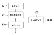
ここで、データ判別が終了したセルに関してはその後の判定でメモリセルに電圧がかからないようにする回路があることが望ましい。例えば、図11に示すように、メモリセル200と負荷抵抗201との間に電源遮断回路202を設け、メモリセル200のデータを読み出して、センスアンプ203で出力した後、電源遮断回路202を作動させて、電源電圧がメモリセル200にかからないようにする。
Here, with respect to the cells for which data discrimination has been completed, it is desirable to have a circuit that prevents voltage from being applied to the memory cells in subsequent judgments. For example, as shown in FIG. 11, a
次に、図12(a)〜(e)に示した工程断面図を参照しながら、本実施形態における半導体記憶装置の製造方法を説明する。 Next, a method for manufacturing the semiconductor memory device according to the present embodiment will be described with reference to process cross-sectional views shown in FIGS.
最初に、図12(a)に示すように、STO基板11上に、パルスレーザ堆積(PLD)法を用いて、基板温度を700℃にした状態で、厚さ30nmのSRO膜を形成する。その上に、レジストを塗布・パターニングした後、イオンミリング法によりSRO膜をエッチングすることにより、第1のゲート電極12を形成する
次に、図12(b)に示すように、酸素雰囲気中で加熱してエッチングダメージを回復した後、基板11上に、PLD法を用いて、基板温度を700℃にした状態で、厚さ450nmのPZT膜13を成長する。このときのターゲットに用いる焼結体の組成は、Pb:Zr:Ti=1:0.52:0.48である。この組成比で形成したPZT膜13と、STO基板11及びSRO膜12との格子ミスマッチは3%以内であり、上記の成長条件下でSRO膜12及びPZT膜13はエピタキシャル成長することができる。この方法で成膜したPZT膜13の表面を原子間力顕微鏡(AFM)で観察したところ、平均二乗粗さは3nm以下と極めて平滑であった。
First, as shown in FIG. 12A, an SRO film having a thickness of 30 nm is formed on the
次いで、PLD装置の同一チャンバー内において、基板温度を400℃にした状態で、厚さ30nmのZnO膜14を形成する。その上に、レジストを塗布・パターニングし、活性領域以外のZnO膜14を希硝酸を用いてエッチングすることにより、チャネル14を形成する。
Next, a
次に、図12(c)に示すように、ZnO膜14上にレジストを塗布・パターニングした後、電子線蒸着法を用いて、厚さ20nmのTi膜、及び厚さ30nmのPt膜を形成した後、溶剤でレジストを除去することにより、所望の位置にソース・ドレイン電極15a〜15fを形成する。
Next, as shown in FIG. 12C, after applying and patterning a resist on the
次に、図12(d)に示すように、スパッタ法を用いて、ZnO膜14上に、厚さ100nmのSiN膜16を形成する。その上に、レジストを塗布・パターニングした後、電子線蒸着法を用いて、厚さ30nmのTi膜及び厚さ170nmのPt膜を形成した後、溶剤でレジストを除去することにより、所望の位置に第2のゲート電極17a、17b、及び第3のゲート電極17cを形成する。
Next, as shown in FIG. 12D, a
次に、図12(e)に示すように、SiN膜16上に、プラズマCVD法を用いて、SiO2膜(層間絶縁膜)18を形成したした後、その上にレジストを塗布・パターニングし、ドライエッチング法を用いてSiO2膜18及びSiN膜16を貫通するコンタクトホールをソース・ドレイン電極上に開口する。そして、開口したコンタクトホール内に、ブランケットCVD法を用いて、タングステンを堆積した後、化学機械研磨(CMP)法を用いて、SiO2膜18表面のタングステンを除去してプラグ19を形成する。最後に、SiO2膜上にスパッタ法を用いてAl膜を形成し、その上にレジストを塗布・パターニングして配線パターンを形成して、図4(a)に示した半導体記憶装置を完成する。
Next, as shown in FIG. 12E, a SiO 2 film (interlayer insulating film) 18 is formed on the
以上、本発明を好適な実施形態により説明してきたが、こうした記述は限定事項ではなく、勿論、種々の改変が可能である。例えば、上記実施形態では、メモリセルを選択スイッチング素子を備えた構成のものを用いたが、メモリ素子がMFSFETで構成されたものであれば、選択スイッチング素子を備えていないメモリセルを用いても、同様の効果を得ることができる。 As mentioned above, although this invention was demonstrated by suitable embodiment, such description is not a limitation matter and of course various modifications are possible. For example, in the above embodiment, a memory cell having a selection switching element is used. However, if the memory element is a MFSFET, a memory cell having no selection switching element may be used. The same effect can be obtained.
また、上記実施形態においては、MFSFETの構造を、金属-強誘電体-半導体の積層構造としたが、金属-強誘電体-常誘電体-半導体の積層構造や、金属と半導体との間に強誘電体を用いた構造(例えば、金属-強誘電体-金属-常誘電体-半導体の積層構造等)としても、同様の効果を得ることができる。 In the above embodiment, the MFSFET has a metal-ferroelectric-semiconductor laminated structure, but a metal-ferroelectric-paraelectric-semiconductor laminated structure, or between a metal and a semiconductor. The same effect can be obtained even in a structure using a ferroelectric (for example, a metal-ferroelectric-metal-paraelectric-semiconductor laminated structure).
また、上記実施形態では、基板11にSTO基板を用いたが、シリコン基板上に絶縁膜を形成したものや、サファイア、ランタン・アルミ酸化物(LaAlO3)からなる基板を用いてもよい。また、強誘電体膜13にPZT膜を用いたが、SrBi2Ta2O9、Bi4−xLaxTi3O12等を用いてもよい。また、チャネルとなる半導体膜14にZnO膜を用いたが、WO3、ITO(InO−SnO)、IGZO(InGaO3(ZnO)5)、STO、LSCO(La2−xSrxCuO4)、LCMO(La1−xCaxMnO3)、PCMO(Pr1−xCaxMnO3)等の、透明なもの、超伝導を示すもの、モット転移を示すものを含む酸化物半導体、あるいは窒化インジウム(InN)、窒化ガリウム(GaN)などの窒化物半導体、多結晶シリコン、アモルファスシリコンなどのIV族半導体などを用いてもよい。また、常誘電体膜16にSiN膜を用いたが、マグネシウムを添加したZnO膜(MgxZn1−xO)、窒化アルミニウム(AlN)膜、酸化アルミニウム(Al2O3)膜などを用いてもよい。また、各電極には、ITO、ZiTO(Zn−In−Sn−O)なども使用することができる。
In the above-described embodiment, the STO substrate is used as the
本発明に係る半導体記憶装置は、強誘電体を用いた不揮発性メモリとして有用であり、すでに実用化されているキャパシタ型の強誘電体不揮発性メモリと比較し、格段にスケーリングメリットがあり、65nmCMOSなどの次世代のプロセス、及び、ロジック上に積層したメモリデバイスとしての応用に期待される。 The semiconductor memory device according to the present invention is useful as a nonvolatile memory using a ferroelectric material, and has a scaling merit as compared with a capacitor-type ferroelectric nonvolatile memory that has already been put into practical use. It is expected to be applied to next-generation processes such as, and memory devices stacked on logic.
11 基板
12 ゲート電極
13 強誘電体膜
14 半導体膜
15a〜15f ソース・ドレイン電極
16 常誘電体膜
17a、17b、17c ゲート電極
18 層間絶縁膜
19 タングステンプラグ
20 アルミニウム配線
21 メモリ素子
22、23 選択スイッチング素子
24 負荷素子
30 第1のワード線
40 第2のワード線
50 第3のワード線
70 ソース線
80 ビット線
100 メモリセル
DESCRIPTION OF
Claims (6)
前記メモリセルに直列に接続された読み出し用の負荷素子と
を備えた半導体記憶装置であって、
前記メモリセルは、前記強誘電体膜の分極状態に応じた、少なくとも3値以上のチャネル抵抗値を多値データとして記憶しており、
前記メモリセルに記憶された多値データは、前記メモリセルと前記負荷素子との間の中間電位を検出することによって読み出され、
前記読み出し動作は、前記メモリセルに記憶された多値データを、前記チャネル抵抗値の高い状態から順に判別することによって実行される、半導体記憶装置。 A memory cell composed of a first field effect transistor having a gate insulating film made of a ferroelectric film and a channel made of a semiconductor film;
A semiconductor memory device comprising a read load element connected in series to the memory cell,
The memory cell stores, as multi-value data, a channel resistance value of at least three or more values according to the polarization state of the ferroelectric film,
The multi-value data stored in the memory cell is read by detecting an intermediate potential between the memory cell and the load element,
The semiconductor memory device, wherein the read operation is executed by sequentially determining the multi-value data stored in the memory cell from a state in which the channel resistance value is high.
前記読み出し動作は、前記第2の電界効果トランジスタのゲート電極に印加する電圧を変化させることによって、前記負荷素子の抵抗値を変化させながら実行される、請求項2に記載の半導体記憶装置。 The load element is composed of a second field effect transistor,
The semiconductor memory device according to claim 2, wherein the read operation is executed while changing a resistance value of the load element by changing a voltage applied to a gate electrode of the second field effect transistor.
前記読み出し動作において、多値データが判別されたメモリセルは、該メモリセルの通電が遮断される、請求項1に記載の半導体記憶装置。 A plurality of the memory cells are arranged,
2. The semiconductor memory device according to claim 1, wherein, in the read operation, the memory cell from which the multi-value data is determined is cut off from energizing the memory cell.
Priority Applications (2)
| Application Number | Priority Date | Filing Date | Title |
|---|---|---|---|
| JP2008150276A JP5081069B2 (en) | 2008-06-09 | 2008-06-09 | Semiconductor memory device |
| US12/405,799 US8004871B2 (en) | 2008-05-26 | 2009-03-17 | Semiconductor memory device including FET memory elements |
Applications Claiming Priority (1)
| Application Number | Priority Date | Filing Date | Title |
|---|---|---|---|
| JP2008150276A JP5081069B2 (en) | 2008-06-09 | 2008-06-09 | Semiconductor memory device |
Publications (2)
| Publication Number | Publication Date |
|---|---|
| JP2009295255A JP2009295255A (en) | 2009-12-17 |
| JP5081069B2 true JP5081069B2 (en) | 2012-11-21 |
Family
ID=41543291
Family Applications (1)
| Application Number | Title | Priority Date | Filing Date |
|---|---|---|---|
| JP2008150276A Expired - Fee Related JP5081069B2 (en) | 2008-05-26 | 2008-06-09 | Semiconductor memory device |
Country Status (1)
| Country | Link |
|---|---|
| JP (1) | JP5081069B2 (en) |
Families Citing this family (7)
| Publication number | Priority date | Publication date | Assignee | Title |
|---|---|---|---|---|
| JP5158293B2 (en) | 2011-05-09 | 2013-03-06 | パナソニック株式会社 | RC oscillator circuit |
| JP5158294B2 (en) | 2011-06-06 | 2013-03-06 | パナソニック株式会社 | RC oscillator circuit |
| US9337210B2 (en) | 2013-08-12 | 2016-05-10 | Micron Technology, Inc. | Vertical ferroelectric field effect transistor constructions, constructions comprising a pair of vertical ferroelectric field effect transistors, vertical strings of ferroelectric field effect transistors, and vertical strings of laterally opposing pairs of vertical ferroelectric field effect transistors |
| US9472560B2 (en) | 2014-06-16 | 2016-10-18 | Micron Technology, Inc. | Memory cell and an array of memory cells |
| US9305929B1 (en) | 2015-02-17 | 2016-04-05 | Micron Technology, Inc. | Memory cells |
| US10134982B2 (en) | 2015-07-24 | 2018-11-20 | Micron Technology, Inc. | Array of cross point memory cells |
| JP2021057446A (en) | 2019-09-30 | 2021-04-08 | ソニーセミコンダクタソリューションズ株式会社 | Semiconductor element, nonvolatile memory device, sum-of-product arithmetic device, and manufacturing method of semiconductor element |
Family Cites Families (4)
| Publication number | Priority date | Publication date | Assignee | Title |
|---|---|---|---|---|
| JP2921812B2 (en) * | 1992-12-24 | 1999-07-19 | シャープ株式会社 | Nonvolatile semiconductor memory device |
| JP2001102465A (en) * | 1999-09-30 | 2001-04-13 | Rohm Co Ltd | Non-volatile memory |
| JP2002270789A (en) * | 2001-03-14 | 2002-09-20 | Toshiba Corp | Ferroelectric memory |
| JP4785180B2 (en) * | 2004-09-10 | 2011-10-05 | 富士通セミコンダクター株式会社 | Ferroelectric memory, multilevel data recording method, and multilevel data reading method |
-
2008
- 2008-06-09 JP JP2008150276A patent/JP5081069B2/en not_active Expired - Fee Related
Also Published As
| Publication number | Publication date |
|---|---|
| JP2009295255A (en) | 2009-12-17 |
Similar Documents
| Publication | Publication Date | Title |
|---|---|---|
| US8004871B2 (en) | Semiconductor memory device including FET memory elements | |
| JP5190275B2 (en) | Semiconductor memory cell and semiconductor memory array using the same | |
| US8385099B2 (en) | Semiconductor memory cell and manufacturing method thereof, and semiconductor memory devices | |
| US8023309B2 (en) | Semiconductor memory device, method for fabricating the same and semiconductor switching device | |
| US11101291B2 (en) | Memory cell arrangement and methods thereof | |
| US7772029B2 (en) | Memory element and memory device comprising memory layer positioned between first and second electrodes | |
| JP4894757B2 (en) | Resistance memory element and nonvolatile semiconductor memory device | |
| US8023318B2 (en) | Resistance memory element, phase change memory element, resistance random access memory device, information reading method thereof, phase change random access memory device, and information reading method thereof | |
| JP5081069B2 (en) | Semiconductor memory device | |
| CN1790719B (en) | Nonvolatile memory device including resistor and transistor | |
| WO2019191393A1 (en) | Systems and methods for gated-insulator reconfigurable non-volatile memory devices | |
| JP2010267704A (en) | Semiconductor memory cell and manufacturing method thereof | |
| JP2010267705A (en) | Semiconductor memory cell and manufacturing method thereof | |
| JPWO2007023569A1 (en) | Nonvolatile semiconductor memory device and writing method thereof | |
| TW202005001A (en) | Semiconductor device and manufacturing method thereof | |
| US5977577A (en) | Ferroelectric based memory devices utilizing low curie point ferroelectrics and encapsulation | |
| WO2012033106A1 (en) | Memory cell block, manufacturing method therefor, memory device, and method for driving a memory device | |
| US6194751B1 (en) | Ferroelectric based memory devices utilizing low Curie point ferroelectrics and encapsulation | |
| JP2008263019A (en) | Semiconductor memory cell and manufacturing method thereof | |
| CN103247627B (en) | Semiconductor memory device and access method thereof | |
| JP2009283877A (en) | Semiconductor memory device | |
| RU2785593C1 (en) | Permanent memory element based on conductive gete ferroelectric | |
| JP2008166486A (en) | Semiconductor memory device | |
| WO2024148515A1 (en) | Multi-state cell and preparation method therefor, array of multi-state cells, and memristor | |
| JP2001267518A (en) | Ferroelectric memory |
Legal Events
| Date | Code | Title | Description |
|---|---|---|---|
| A621 | Written request for application examination |
Free format text: JAPANESE INTERMEDIATE CODE: A621 Effective date: 20101116 |
|
| RD02 | Notification of acceptance of power of attorney |
Free format text: JAPANESE INTERMEDIATE CODE: A7422 Effective date: 20120201 |
|
| TRDD | Decision of grant or rejection written | ||
| A01 | Written decision to grant a patent or to grant a registration (utility model) |
Free format text: JAPANESE INTERMEDIATE CODE: A01 Effective date: 20120807 |
|
| A01 | Written decision to grant a patent or to grant a registration (utility model) |
Free format text: JAPANESE INTERMEDIATE CODE: A01 |
|
| A61 | First payment of annual fees (during grant procedure) |
Free format text: JAPANESE INTERMEDIATE CODE: A61 Effective date: 20120831 |
|
| FPAY | Renewal fee payment (event date is renewal date of database) |
Free format text: PAYMENT UNTIL: 20150907 Year of fee payment: 3 |
|
| R150 | Certificate of patent or registration of utility model |
Free format text: JAPANESE INTERMEDIATE CODE: R150 |
|
| LAPS | Cancellation because of no payment of annual fees |


