JP5080997B2 - Ophthalmic imaging equipment - Google Patents
Ophthalmic imaging equipment Download PDFInfo
- Publication number
- JP5080997B2 JP5080997B2 JP2008013985A JP2008013985A JP5080997B2 JP 5080997 B2 JP5080997 B2 JP 5080997B2 JP 2008013985 A JP2008013985 A JP 2008013985A JP 2008013985 A JP2008013985 A JP 2008013985A JP 5080997 B2 JP5080997 B2 JP 5080997B2
- Authority
- JP
- Japan
- Prior art keywords
- alignment
- target
- eye
- split
- observation
- Prior art date
- Legal status (The legal status is an assumption and is not a legal conclusion. Google has not performed a legal analysis and makes no representation as to the accuracy of the status listed.)
- Active
Links
Images


Landscapes
- Eye Examination Apparatus (AREA)
Description
本発明は、眼底カメラ等のように、スプリット光学系、アライメント系、観察光学系、撮影光学系を備えた眼科撮影装置に関する。 The present invention relates to an ophthalmologic photographing apparatus including a split optical system, an alignment system, an observation optical system, and a photographing optical system, such as a fundus camera.
眼底カメラにおいて撮影を行う場合、調整ノブを回して焦点を調整し、二つに分離しているアライメント輝点を中心で合致させた後、撮影ボタンを押して撮影を行う。また、瞳孔が小さい被検者には、小瞳孔絞りを入れる場合がある。 When photographing with a fundus camera, the adjustment knob is turned to adjust the focus, the alignment bright points separated into two are matched at the center, and then the photographing button is pressed to perform photographing. A subject with a small pupil may be provided with a small pupil stop.
しかし、検者としては、眼底カメラに不慣れな者や、片手で被検者の瞼を押さえ、もう一方の手のみで操作する者等が存在し、これらの検者にとって、手動によるカメラ操作は困難であった。 However, there are some examiners who are unfamiliar with the fundus camera or those who hold the subject's eyelid with one hand and operate with only the other hand. It was difficult.
これに対し、検者の合焦操作負担を軽減するために、自動フォーカスを行う眼底カメラが知られている(例えば、特許文献1参照)。また、検者のアライメント調整操作負担を軽減するために、自動アライメントを行う眼底カメラも知られている(例えば、特許文献2参照)。さらに、自動アライメントと自動フォーカスを組み合わせた自動撮影モードを持った眼底カメラも知られている(例えば、特許文献3参照)。
しかしながら、特許文献1に記載の眼底カメラにあっては、自動フォーカスのみを行うため、検者によるアライメント調整操作負担が残る、という問題があった。
However, the fundus camera described in
また、特許文献2に記載の眼底カメラにあっては、自動アライメントのみを行うため、検者による合焦操作負担が残ると共に、2つのアライメント輝点を各々点滅させる機構が必要である、という問題があった。
Further, in the fundus camera described in
さらに、特許文献3に記載の眼底カメラにあっては、前眼部表示状態で自動アライメントを作動させ、眼底表示状態で自動フォーカスを作動させるものであるため、前眼部表示状態で自動アライメントを作動させた後、自動フォーカスを作動させる場合、前眼部から眼底へ表示状態を切り換える必要がある。そして、自動フォーカスの作動中にアライメント条件が成立しなくなった場合、眼底から前眼部へ表示状態を切り換える必要がある。ちなみに、被検者の眼球は、前眼部も眼底も球面状であるため、自動アライメントと自動フォーカスの一方を作動させると、他方にズレ影響が出るという相関関係にある。したがって、特許文献3に記載の眼底カメラでは、表示状態を切り換えて自動アライメントと自動フォーカスを繰り返し行う必要があるため、自動撮影モードを開始してから自動フラッシュ撮影動作に入るまで、観察画面が不規則に変化するし、自動フラッシュ撮影動作に入るまでに時間を要する、という問題があった。
Furthermore, in the fundus camera described in
加えて、特許文献3に記載の眼底カメラでは、アライメント条件とフォーカス条件と視線/瞳孔径条件が共に成立しないと、自動フラッシュ撮影を行えない。このため、アライメント条件とフォーカス条件が成立しても視線/瞳孔径条件が成立しない限り、いくら待っても自動フラッシュ撮影を行えないし、視線/瞳孔径条件が成立しない被検者は、自動フラッシュ撮影の対象外となる。
In addition, the fundus camera described in
本発明は、上記問題に着目してなされたもので、合焦とアライメント調整の操作負担を軽減し、観察画面が不規則に変化することなく、自動撮影を開始してから応答良く自動フラッシュ撮影動作を実行することができる眼科撮影装置を提供することを目的とする。 The present invention has been made paying attention to the above-mentioned problems, reduces the burden of focusing and alignment adjustment, and does not change the observation screen irregularly. An object of the present invention is to provide an ophthalmologic photographing apparatus capable of executing an operation.
上記目的を達成するため、本発明では、被検眼の撮影対象部分に合焦するためスプリット視標を投影するスプリット光学系と、被検眼に対して装置本体を位置合わせするためアライメント視標を投影するアライメント系と、前記被検眼の撮影対象像を前記スプリット視標および前記アライメント視標と共に表示する観察モニタを含む観察光学系と、前記被検眼の撮影対象像を撮影するカメラを含む撮影光学系と、を備えた眼科撮影装置において、
前記観察光学系に撮影対象部分と共に表示されるスプリット視標の位置認識に基づき、被検眼の撮影対象部分に合焦させるフォーカス動作と、前記観察光学系に撮影対象部分と共に表示されるアライメント視標の位置認識に基づき、被検眼に対して装置本体を位置合わせするアライメント動作を行い、合焦と位置合わせの最終確認結果が適正範囲内になると、自動フラッシュ撮影動作を実行する自動撮影制御手段を設け、
前記自動撮影制御手段は、前記観察光学系の観察映像信号により認識されるスプリット視標が1つであるというスプリット視標条件と、2つのアライメント視標が規定の範囲内にあるというアライメント合致条件が共に成立すると、被検眼が小瞳孔であると判定し、自動フラッシュ撮影動作を行う前、自動的に小瞳孔絞りを挿入する小瞳孔絞り挿入制御部を有することを特徴とする。
In order to achieve the above object, the present invention projects a split optical system that projects a split target to focus on the imaging target portion of the eye and an alignment target that aligns the apparatus main body with respect to the eye. An imaging optical system including an alignment optical system, an observation optical system including an observation monitor that displays an imaging target image of the eye to be inspected together with the split target and the alignment target, and a camera that captures the imaging target image of the eye to be inspected In an ophthalmologic photographing apparatus comprising:
Based on the position recognition of the split target displayed together with the imaging target part on the observation optical system, a focus operation for focusing on the imaging target part of the eye to be inspected, and the alignment target displayed together with the imaging target part on the observation optical system Based on the position recognition, an alignment operation for aligning the apparatus main body with respect to the eye to be examined is performed, and when the final confirmation result of focusing and alignment is within an appropriate range, an automatic imaging control means for executing an automatic flash imaging operation is provided. Provided ,
The automatic photographing control means includes a split target condition that one split target is recognized by an observation video signal of the observation optical system and an alignment matching condition that two alignment targets are within a specified range. If both are established, it is determined that the subject's eye is a small pupil and has a small pupil stop insertion control unit that automatically inserts the small pupil stop before performing the automatic flash photographing operation .
よって、本発明の眼科撮影装置にあっては、自動撮影制御手段において、観察光学系に撮影対象部分と共に表示されるスプリット視標の位置認識に基づき、被検眼の撮影対象部分に合焦させるフォーカス動作が行われ、観察光学系に撮影対象部分と共に表示されるアライメント視標の位置認識に基づき、被検眼に対して装置本体を位置合わせするアライメント動作が行われる。そして、合焦と位置合わせの最終確認結果が適正範囲内になると、自動フラッシュ撮影動作が実行される。
このように、観察光学系に表示されるスプリット視標とアライメント視標を用い、同じ撮影対象部分の表示を保ったままで、フォーカス動作とアライメント動作が行われるため、観察モニタに映し出される観察画面が不規則に変化することがない。
また、表示状態の切換を行うことなく、フォーカス動作とアライメント動作が行われるため、表示状態の切換処理時間を要さない。加えて、視線/瞳孔径条件等を自動フラッシュ撮影条件に含まないため、視線/瞳孔径条件等の成立待ち時間を要さない。よって、自動撮影を開始してから自動フラッシュ撮影動作を実行するまでの無駄時間を最小に抑えることができる。
この結果、合焦とアライメント調整の操作負担を軽減し、観察画面が不規則に変化することなく、自動撮影を開始してから応答良く自動フラッシュ撮影動作を実行することができる。
加えて、被検眼が小瞳孔であると判定されると、自動フラッシュ撮影動作を行う前、自動的に小瞳孔絞りを挿入する小瞳孔絞り挿入制御部を有するため、被検者が小瞳孔であっても、自動的に小瞳孔絞りが挿入されることで、小瞳孔の被検者も自動撮影の対象に含めることができる。
Therefore, in the ophthalmologic photographing apparatus of the present invention, in the automatic photographing control means, the focus for focusing on the photographing target portion of the eye to be examined based on the position recognition of the split target displayed together with the photographing target portion on the observation optical system. An operation is performed, and an alignment operation for aligning the apparatus main body with respect to the eye to be examined is performed based on the position recognition of the alignment target displayed together with the imaging target portion on the observation optical system. When the final confirmation result of in-focus and alignment is within an appropriate range, an automatic flash photographing operation is executed.
In this way, since the focus operation and the alignment operation are performed using the split target and the alignment target displayed on the observation optical system while keeping the display of the same photographing target part, the observation screen displayed on the observation monitor is displayed. It does not change irregularly.
Further, since the focus operation and the alignment operation are performed without switching the display state, the display state switching processing time is not required. In addition, since the line-of-sight / pupil diameter condition or the like is not included in the automatic flash imaging conditions, the waiting time for establishing the line-of-sight / pupil diameter condition or the like is not required. Therefore, the dead time from the start of automatic shooting to the execution of the automatic flash shooting operation can be minimized.
As a result, the operation burden of focusing and alignment adjustment can be reduced, and the automatic flash photographing operation can be executed with good response after starting the automatic photographing without irregularly changing the observation screen.
In addition, when the subject's eye is determined to be a small pupil, the subject has a small pupil stop insertion control unit that automatically inserts a small pupil stop before performing an automatic flash photographing operation. Even if it exists, the subject of a small pupil can also be included in the object of automatic imaging | photography by inserting a small pupil aperture automatically.
以下、本発明の眼科撮影装置を実現する最良の形態を、図面に示す実施例1に基づいて説明する。 Hereinafter, the best mode for realizing the ophthalmologic photographing apparatus of the present invention will be described based on Example 1 shown in the drawings.
まず、構成を説明する。
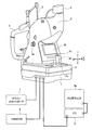
図1は、実施例1の無散瞳眼底カメラ(眼科撮影装置の一例)を示す全体システム図である。ここで、「無散瞳眼底カメラ」とは、眼底カメラの中で、散瞳薬を使わないで、暗室である程度散瞳させた後、眼底観察やフラッシュを当てて眼底写真をとる眼底カメラをいう。この無散瞳眼底カメラの長所は、検査後の視力的不自由が無く、簡便さから眼科のみならず内科や健康診断でも使われる。欠点は、散瞳が不十分であるため網膜の中央部分しか撮影できない。このため、糖尿病性網膜症等による小瞳孔の場合への対応性が要求される。
First, the configuration will be described.
FIG. 1 is an overall system diagram illustrating a non-mydriatic fundus camera (an example of an ophthalmologic photographing apparatus) according to the first embodiment. Here, the “non-mydriatic retinal camera” refers to a retinal camera that takes a photo of the fundus by observing the fundus and applying a flash after performing mydriasis to some extent in the dark room without using mydriatic drugs. Say. The advantage of this non-mydriatic fundus camera is that there is no visual inconvenience after the examination, and it is used not only in ophthalmology but also in internal medicine and medical examinations for simplicity. The disadvantage is that the mydriatic is insufficient, so that only the central part of the retina can be photographed. For this reason, the response | compatibility to the case of the small pupil by diabetic retinopathy etc. is requested | required.
実施例1の無散瞳眼底カメラは、図1に示すように、装置ベース1と、架台部2と、装置本体3と、顎受け4と、外部固視標5と、撮影用CCDカメラ6(カメラ)と、マウス/10キーボード7と、プリンタ8と、パーソナルコンピュータ9と、を備えている。
As shown in FIG. 1, the non-mydriatic fundus camera of the first embodiment includes an
前記装置ベース1は、図外の装置テーブルに水平に設置され、電源プラグや複数の接続端子が設けられている。この装置ベース1は、電源部・顎受けPCB・中継PCB等を内蔵する。なお、「PCB」とは、Printed Circuit Boardの略であり、IC等によるプリント基板のことをいう。
The
前記架台部2は、前記装置ベース1に対し左右方向・前後方向・上下方向に移動可能に設けられている。この架台部2の検者側の位置には、操作パネル2a、ジョイスティック2b、撮影スイッチ2c等が設けられる。
The
前記装置本体3は、前記架台部2の上部に一体的に設けられたもので、装置本体3の側部位置には、合焦ハンドル3aが設けられている。また、この装置本体3の検者側位置には、観察LCDユニット31(図5参照)の構成要素である観察モニタ3b(例えば、6.5型カラー液晶モニタ)が設けられている。なお、「LCD」とは、Liquid Crystal Displayの略であり、液晶ディスプレイのことをいう。
The apparatus
前記顎受け4は、前記装置ベース1に対し上下方向の位置が調整可能に設けられたもので、被検者の顎と額を受けて被検眼の位置を固定させる。この顎受け4には、被検者の視線を固定するための外部固視標5が設けられている。
The chin rest 4 is provided so that the position in the vertical direction can be adjusted with respect to the
前記撮影用CCDカメラ6は、前記装置本体3の上部位置に外付けにて設定されたもので、実施例1の無散瞳眼底カメラが持つオートシュート機能により、眼底のフラッシュ撮影を行う。この撮影用CCDカメラ6としては、市販のAPSサイズのデジタルカメラが用いられる。また、撮影用CCDカメラ6は、装置ベース1に内蔵した電源部から電源供給を受ける。
The photographing
前記マウス/10キーボード7と前記プリンタ8と前記パーソナルコンピュータ9は、前記装置ベース1の複数の接続端子にケーブルを介して接続される。また、前記パーソナルコンピュータ9には、大型画面にて眼底観察を行うことができるPC用モニタ9aが接続されている。
The mouse / 10
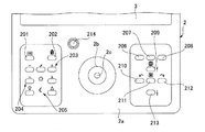
図2は、実施例1の無散瞳眼底カメラにおける架台部に設定された操作パネルを示す平面図である。以下、操作パネル2aに設定された各スイッチ類について説明する。
FIG. 2 is a plan view showing an operation panel set on the gantry in the non-mydriatic retinal camera of the first embodiment. Hereinafter, each switch set on the
実施例1の無散瞳眼底カメラにおける架台部2に設定された操作パネル2aは、図2に示すように、ジョイスティック2bと、撮影スイッチ2cと、メニュースイッチ201と、スプリットスイッチ202と、撮影光量補正スイッチ203と、観察光量補正スイッチ204と、顎受け上下動スイッチ205と、ID入力スイッチ206と、画像削除スイッチ207と、画像再生スイッチ208と、小瞳孔スイッチ209と、固視切換えスイッチ210,211,212と、オートON/OFFスイッチ213と、変倍スイッチ214と、を備えている。
As shown in FIG. 2, the
前記ジョイスティック2bは、手動によるアライメント操作時、装置ベース1に対し架台部2および装置本体3を左右方向(X方向)・上下方向(Y方向)・前後方向(Z方向)に移動させる操作手段である。左右方向と前後方向は、ジョイスティック2bを把持し、移動させたい左右方向や前後方向に傾けることで移動する。このとき、架台前後検知スイッチ215と架台左右検知スイッチ216が入る(図5参照)。また、ジョイスティック2bの上部の操作リングを右方向に回転させることで上方向に移動し、左方向に回転させることで下方向に移動する。
The
前記撮影スイッチ2cは、前記ジョイスティック2bの上端部位置に設けられ、検者が押し込むスイッチ操作を行うことで、眼底の撮影シャッタースイッチとなる。なお、撮影スイッチ2cは、撮影機能以外に、レビュー解除やパワーセーブ解除も行う。
The photographing
前記メニュースイッチ201は、メニューのON/OFFを行う。
The
前記スプリットスイッチ202は、「スプリットのON/OFF」または「固視標の切換え」を行う。この機能の変更は、初期メニューの“SPLIT SWITCH”で行う。
The
前記撮影光量補正スイッチ203は、撮影光量の補正を行う。図2の左から、マイナス補正スイッチ、リセットスイッチ、プラス補正スイッチである。
The photographing light
前記観察光量補正スイッチ204は、観察光量の補正を行う。図2の左から、マイナス補正スイッチ、プラス補正スイッチである。
The observation light
前記顎受け上下動スイッチ205は、顎受け4の上下動を行う。図2の左から、顎受け下動スイッチ、顎受け上動スイッチである。
The chin rest
前記ID入力スイッチ206は、ID入力画面に移動するスイッチである。
The
前記画像削除スイッチ207は、レビューした撮影画像を削除する場合にON/OFFする。
The
前記画像再生スイッチ208は、スイッチをONにすることによりデジタルスチルカメラ6の画像を再生することが可能になる。固視切換えスイッチ210をONする毎に一枚前に撮影した画像を再生する。また、固視切換えスイッチ212をONする毎に一枚後に撮影した画像を再生する。スイッチをOFFにすると観察画面に戻る。
The
前記小瞳孔スイッチ209は、スイッチをON/OFFすることにより、小瞳孔絞りのIN/OUTを行う。オートON/OFFスイッチ213がONの時にも独立して機能する。ONとなった場合は観察モニタ3bの画面上に◎が表示される。デジタル変倍連動モードに設定した場合、小瞳孔絞りをON時にデジタル変倍30°でイメージネットに保存する。また、プリントした場合は、デジタル変倍30°での画像をプリントアウトする。デジタル変倍非連動モードに設定した場合、小瞳孔絞りをON時にもデジタル変倍せず45°のままとする。なお、この小瞳孔スイッチ209は、メニューやID入力時、選択カーソルを上方向に移動させるスイッチを兼用する。
The
前記固視切換えスイッチ210は、現在の内部固視標の点滅(点灯)位置の一つ前の点滅(点灯)位置に切り換える。なお、この固視切換えスイッチ210は、メニューやID入力時、選択カーソルを左方向に移動させるスイッチを兼用する。
The
前記固視切換えスイッチ211は、現在の内部固視標の点滅(点灯)位置から最初の点滅(点灯)位置に切り換える。なお、この固視切換えスイッチ211は、プリントスイッチとエンタースイッチを兼用する。プリントスイッチの場合、ONにするとレビューした画像をプリントする。メニュー設定にて自動プリントに設定されていた場合とプリント表示が観察画面に表示されていた場合にONにすると、プリント中止となる。エンタースイッチの場合、メニューやID入力時、選択項目や文字の決定をする。
The
前記固視切換えスイッチ212は、現在の内部固視標の点滅(点灯)位置の一つ次の点滅(点灯)位置に切り換える。なお、この固視切換えスイッチ212は、メニューやID入力時、選択カーソルを右方向に移動させるスイッチを兼用する。
The
前記オートON/OFFスイッチ213と、オートシュート機能/オートフォーカス機能/オート小瞳孔機能のON/OFFを行う。ここで、各機能のON/OFFは、メニューにより設定可能である。なお、このオートON/OFFスイッチ213は、メニューやID入力時、選択カーソルを下方向に移動させるスイッチを兼用する。
The auto on / off
前記変倍スイッチ214は、2変倍の眼底撮影を行うために、撮影画角を30°と45°に切り換えるスイッチである。
The
図3は、実施例1の無散瞳眼底カメラにおける装置本体に設定された観察モニタへ表示される各表示内容を示すイメージ図である。以下、各表示内容について説明する。 FIG. 3 is an image diagram showing display contents displayed on the observation monitor set in the apparatus main body of the non-mydriatic fundus camera of the first embodiment. Hereinafter, each display content will be described.
実施例1の無散瞳眼底カメラの場合、装置本体3の情報とデジタルスチルカメラ6の情報を、図3に示すように、観察モニタ3bに表示する。観察時、レビュー時、再生時、メニュー時の各表示としては、患者ID301と、左右眼302と、キセノン充電303と、撮影光量補正304と、撮影光量レベル305と、オート表示306と、画角307と、固視位置308と、()スケール309と、アライメント輝点310,310(アライメント視標)と、スプリット輝線311,311(スプリット視標)と、観察光量レベル312と、小瞳孔絞り313と、を有する。
In the case of the non-mydriatic fundus camera of the first embodiment, the information of the apparatus
前記患者ID301は、撮影する画像の患者IDを表示する。前記左右眼302は、撮影する被検者の左右眼(R,L)を表示する。前記キセノン充電303は、充電中は点滅し、充電完了で点灯する。前記撮影光量補正304は、パネルスイッチ217(図5参照)での補正量(+4〜-4)を表示する。前記撮影光量レベル305は、撮影光量(0.8ws〜45ws)を表示する。
The
前記オート表示306は、オートシュート/オートフォーカス/オート小瞳孔切換えがONになっている場合に表示する。前記画角307は、撮影される画像倍率を表示する。例えば、デジタル変倍を小瞳孔絞り連動モードに設定した場合、小瞳孔絞りをON時に30°を表示する。前記固視位置308は、選択されている固視位置を点滅させることにより、内部固視位置パターンを表示する。
The
前記()スケール309は、アライメント輝点を合致させる位置として表示する。前記アライメント輝点310,310は、被検者のワーキングディスタンスを合わせるための視標として表示する。前記スプリット輝線311,311は、被検者の視度を合わせるための視標として表示する。前記観察光量レベル312は、観察光量レベルを5段階にて表示する。前記小瞳孔絞り313は、小瞳孔絞りが挿入されている時は◎を表示する。
The ()
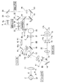
図4は、実施例1の無散瞳眼底カメラにおける装置本体3に内蔵された光学系を示す光学配置図である。以下、無散瞳眼底カメラの光学系の配置構成を説明する。
FIG. 4 is an optical arrangement diagram showing an optical system built in the apparatus
前記装置本体3の内部には、図4に示すように、被検眼Eの眼底Efを照明するための照明光学系10と、眼底Efを撮影する撮影光学系20と、眼底Efを観察する観察光学系30と、被検眼Eに対する装置本体3の相対位置合わせを行うためのアライメント系40と、眼底Efに固視標を投影して被検眼Eを固視させるための内部固視系50と、眼底Efに光学系の焦点合わせを行うためのスプリット光学系60と、が設けられている。
Inside the apparatus
前記照明光学系10は、観察時には赤外光により眼底Efを照明し、撮影時には可視光により眼底Efを照明する照明光学系である。この照明光学系10は、対物レンズ11、穴空きミラー12、リレーレンズ13、反射ミラー14、リレーレンズ15、被検眼Eの瞳孔と共役関係に保たれたリング開口16aを有するリング開口板16と、撮影光源としてのキセノンランプ17aと、IRフィルタ18と、コンデンサレンズ19と、観察照明光源としてのハロゲンランプ17bとを有している。また、被検眼Eと対物レンズ11との距離Wは、適正作動距離に配置された場合、穴空きミラー12は被検眼Eの角膜Cと共役な位置に配置されている。
The illumination
前記撮影光学系20は、照明光学系10により照明された眼底Efを静止画像として撮影するための光学系である。この撮影光学系20は、対物レンズ11と、穴空きミラー12と、合焦レンズ21と、結像レンズ22と、反射ミラー23と、フィールドレンズ24と、反射ミラー25と、リレーレンズ26と、撮影用CCDカメラ6のCCD6aと、を有する。
The photographing
前記観察光学系30は、照明光学系10により照明された眼底Efを観察するための光学系であり、撮影光学系20の光路の途中からクイックリターンミラー33により分岐して構成される。この観察光学系30は、反射ミラー35と、リレーレンズ36と、観察用CCDカメラ37のCCD37aと、を有する。
The observation
アライメント系40は、アライメント視標であるアライメント輝点310,310を被検眼Eに向けて投影するためのものである。このアライメント系40は、アライメント光源としてのアライメントLED41と、該アライメントLED41の光を導くライトガイド42と、ライトガイド42から射出された光を反射させて2孔絞り43に導く反射鏡44と、リレーレンズ45と、撮影光学系20からの分岐用ハーフミラー46と、穴空きミラー12と、対物レンズ11と、を有する。2孔絞り43は、作動距離Wが適正位置からずれたときにアライメント光束に基づくアライメント輝点310,310を分離して被検眼Eに投影する。
すなわち、ライトガイド42の射出端42aから出射されたアライメント光束は、反射鏡44により反射された2孔絞り43に導かれ、2孔絞り43の孔部43a,43aを通ったアライメント光束は、リレーレンズ45に導かれる。リレーレンズ45を通過したアライメント光束は、ハーフミラー46により穴空きミラー12に向けて反射される。リレーレンズ45は、ライトガイド42の射出端42aを、穴空きミラー12の孔部12aの中央位置Xに一旦中間結像する。その孔部12aの中央位置Xに結像されたアライメント視標を形成する一対のアライメント輝点310,310は、対物レンズ11を介して被検眼Eの角膜Cに導かれる。
The
That is, the alignment light beam emitted from the
前記内部固視系50は、被検眼Eの中心部とその周辺部に誘導させるための固視標を投影する光学系であり、観察光学系30の光路の途中から赤外光を透過し、可視光を反射する特性を有するダイクロイックミラー53により分岐されて配置されている。この固視系50は、内部固視光源としての内部固視LED51と、マスク板52と、ダイクロイックミラー53と、を有する。前記内部固視LED51としては、例えば、中央に配置された3個のLEDと、該3個のLEDを中心として円周上に等間隔に配置された8個のLEDと、を有して構成される。
The
前記スプリット光学系60は、スプリット輝線311,311の投影光学系であり、スプリット光源としてのスプリットLED61と、前記照明光学系10の光路中に設けられ、スプリットLED61からの光を反射する反射棒62と、を有する。前記反射棒62は、被検眼Eの眼底Efと光学的に共役可能な位置に挿脱可能に挿入されている(その詳細構成は、例えば、特開平9−66032号公報参照)。このスプリット光学系60は、スプリット輝線311,311の反射棒62の反射ミラーと眼底Efが常に光学的に共役となるように、観察光学系30及び撮影光学系20の合焦レンズ21のZ方向への移動と連動し、照明光学系10の光軸方向に移動するようになっている。眼底Efとスプリット輝線311,311とが共役になっていない場合、図3に示すように、スプリット輝線311,311が左右方向に二つに分離して見え、スプリット輝線311,311を一つに揃えることにより、ピント合わせを行うことができる。
The split
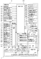
図5は、実施例1の無散瞳眼底カメラにおける装置ベース1と架台部2と装置本体3に内蔵された制御系を示す電気ブロック図である。以下、無散瞳眼底カメラの電気制御系の構成を説明する。
FIG. 5 is an electrical block diagram illustrating a control system built in the
前記装置ベース1には、図5に示すように、顎受けPCB101と、顎受けDCモータ102と、外部固視LED103と、交流電源供給プラグ104と、ヒューズ105と、電源供給スイッチ106と、電源供給切り換え部107と、中継PCB108と、を備えている。そして、前記中継PCB108には、テンキー用PS2コネクタ109と、プリンタ用USBコネクタ110と、マウス用USBコネクタ111と、イメージネット用USBコネクタ112と、を有する。
As shown in FIG. 5, the
前記架台部2には、図5に示すように、撮影スイッチ2cと、メニュースイッチ201と、スプリットスイッチ202と、撮影光量補正スイッチ203と、観察光量補正スイッチ204と、顎受け上下動スイッチ205と、ID入力スイッチ206と、小瞳孔スイッチ209と、固視切換えスイッチ210,211,212と、オートON/OFFスイッチ213と、変倍スイッチ214と、架台前後検知スイッチ215と、架台左右検知スイッチ216と、パネルスイッチ217と、を備えている。
As shown in FIG. 5, the
前記装置本体3には、図5に示すように、撮影用CCDカメラ6と、キセノンランプ17aと、ハロゲンランプ17bと、観察LCDユニット31と、観察用CCDカメラ37と、本体PCB315と、ボードPC316と、撮影カメラ中継PCB317と、DC電源PCB318と、キャプチャボード319と、を備えている。なお、前記DC電源PCB318には、ハロゲンランプ制御部318aと、キセノンランプ制御部318bを有する。
As shown in FIG. 5, the apparatus
前記本体PCB315への情報入力手段として、図5に示すように、瞬き検知PCB320と、グリーンフィルタ検知スイッチ321と、視度補正レンズ検知スイッチ322と、ランプハウスカバー検知スイッチ323と、アライメントモータ検知センサ324と、クイックミラーモータ検知センサ325と、オートフォーカスモータ(+)検知センサ326と、オートフォーカスモータ(-)検知センサ327と、を備えている。
As information input means to the
前記本体PCB315からの制御指令出力手段として、図5に示すように、冷却ファン328と、アライメントモータ330(アライメントアクチュエータ)と、クイックミラーモータ331と、オートフォーカスモータ332(オートフォーカスアクチュエータ)と、水晶体絞り駆動ソレノイド333と、前眼部切換え駆動ソレノイド334と、反射棒駆動ソレノイド335と、スプリットLED61と、アライメントLED41と、手元照明LED336と、内部固視LED51と、を備えている。
As shown in FIG. 5, the control command output means from the
前記本体PCB315と前記ボードPC316は、シリアル通信によりデータ交換される。前記本体PCB315と前記撮影カメラ中継PCB317は、双方向通信によりデータ交換される。前記ボードPC316と前記撮影カメラ中継PCB317、前記ボードPC316と前記中継PCB108、前記撮影カメラ中継PCB317と前記中継PCB108は、それぞれ双方向通信によりデータ交換される。
The
前記本体PCB315は、下記の機能を担う。
(1)センサ検知
瞬き/グリーンフィルタ/視度補正レンズ/ランプハウスカバー/アライメント・クイックミラー/オートフォーカスモータの検知を行う。
(2)モータ駆動
アライメント/クイックミラー/オートフォーカスモータの駆動制御を行う。
(3)ソレノイド駆動
水晶体絞り/前眼部切換え/反射棒ソレノイドの駆動制御を行う。
(4)LED点灯
スプリット/アライメント/手元照明/内部固視の点灯・点滅を制御する。
(5)スイッチ信号の読み込み
架台部2からの各種スイッチ信号の読み込みを行う。
The
(1) Sensor detection blink / green filter / diopter correction lens / lamp house cover / alignment quick mirror / auto focus motor.
(2) Motor drive alignment / Quick mirror / Auto focus motor drive control.
(3) Solenoid drive lens aperture / anterior eye part switching / reflector solenoid drive control.
(4) LED lighting Controls lighting / flashing of split / alignment / hand illumination / internal fixation.
(5) Reading switch signals Various switch signals are read from the
前記ボードPC316(シングルボードコンピュータ)は、下記の機能を担う。
(1)ダイレクトプリント機能
撮影用CCDカメラ6で撮影した画像をプリンタ8へ直接転送する機能をいう。撮影用CCDカメラ6の本体にもピクトブリッジ機能は実装されているが、印刷する際に撮影用CCDカメラ6の本体を操作する必要があり、操作性が悪い。そこで、一連の撮影動作の内部にプリントアウト機能を含めることにより操作を簡略化する。
(2)オートフォーカス機能
観察用CCDカメラ37のCCD37aから得られる観察映像信号上のスプリット輝線311,311の状態を解析し、オートフォーカスを実現する機能をいう。映像信号の解析をボードコンピュータにおいて実行することにより、専用PC板を使用することなくオートフォーカスを実行できる。
(3)オートシュート機能(=自動フラッシュ撮影動作機能)
観察用CCDカメラ37のCCD37aから得られる観察映像信号上のアライメント輝点310,310とスプリット輝線311,311の状態を解析し、自動フラッシュ撮影動作を実現する機能をいう。上記オートフォーカスと同様に、映像信号の解析をボードコンピュータにおいて実行することにより、専用PC板を使用することなくオートシュートを実行できる。
(4)オート小瞳孔切換え機能
観察用CCDカメラ37のCCD37aから得られる観察映像信号上のスプリット輝線311,311の状態を解析し、小瞳孔の場合、自動的に絞りを挿入する機能をいう。上記オートフォーカスと同様に、映像信号の解析をボードコンピュータにおいて実行することにより、専用PC板を使用することなくオート小瞳孔切換えを実行できる。
(5)モニタ表示機能
観察像及び撮影像を観察モニタ3bに表示する。
The board PC 316 (single board computer) has the following functions.
(1) Direct print function A function for directly transferring an image taken by the
(2) Autofocus function A function that realizes autofocus by analyzing the states of split
(3) Auto-shoot function (= automatic flash shooting function)
This is a function for analyzing the states of alignment
(4) Auto small pupil switching function This means a function of analyzing the state of split
(5) Monitor display function An observation image and a photographed image are displayed on the
前記DC電源PCB318は、下記の機能を担う。
(1)ハロゲンランプ制御部318aにてハロゲンランプ17bの発光を制御する。
(2)キセノンランプ制御部318bにてキセノンランプ17aの発光を制御する。
The DC
(1) The halogen lamp controller 318a controls the light emission of the
(2) The light emission of the
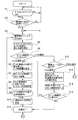
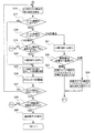
図6は、実施例1の無散瞳眼底カメラにおけるボードPC316にて実行されるオートフォーカス制御動作の流れを示すフローチャートである。図7は、実施例1の無散瞳眼底カメラにおけるボードPC316で実行されるオートシュート制御動作の流れ(オートフォーカス制御動作の流れの繰り返しを含む)を示すフローチャートである。以下、各ステップについて説明する(自動撮影制御手段)。
FIG. 6 is a flowchart illustrating a flow of an autofocus control operation executed by the
ステップS1では、オートON/OFFスイッチ213がONであるか否かを判断する。YES(オートON/OFFスイッチON)と判断された場合はステップS2へ移行し、NO(オートON/OFFスイッチOFF)と判断された場合はステップS1での判断を繰り返す。
In step S1, it is determined whether or not the auto ON /
ステップS2では、ステップS1でのオートON/OFFスイッチONとの判断に続き、前眼部観察から眼底観察に切り換わったか否かを判断する。YES(前眼部観察→眼底観察)と判断された場合はステップS3へ移行し、NO(前眼部観察のまま、あるいは、眼底観察のまま)と判断された場合はステップS1へ戻る。 In step S2, following the determination of the auto ON / OFF switch ON in step S1, it is determined whether or not the anterior ocular segment observation has been switched to the fundus oculi observation. If it is determined YES (anterior ocular segment observation → fundus observation), the process proceeds to step S3. If it is determined NO (no anterior segment observation or fundus observation), the process returns to step S1.
ステップS3では、ステップS2での前眼部観察から眼底観察に切り換わったとの判断に続き、キャプチャボード319を介して観察用CCDカメラ37のCCD37aから得られる眼底観察像を1フレーム分だけ取り込み、ステップS4へ移行する。
In step S3, following the determination that the anterior ocular segment observation has been switched to fundus observation in step S2, the fundus observation image obtained from the
ステップS4では、ステップS3での眼底観察像の取り込みに続き、オートフォーカスのためのスプリット輝線311,311の重心位置を検出し、ステップS5へ移行する。
ここで、スプリット輝線311,311の重心位置検出は、取り込まれた眼底観察像中のスプリット輝線311,311の輝度分布特性において、輝度が閾値以上である領域の中心点を重心位置として検出するようにしている。
In step S4, following the acquisition of the fundus observation image in step S3, the barycentric positions of the split
Here, the center-of-gravity position detection of the split
ステップS5では、ステップS4でのスプリット輝線311,311の重心位置検出に続き、スプリット輝線311,311の数が1つ以下か否かが判断される。スプリット輝線311,311の数が2つであると判断された場合はステップS6へ移行し、スプリット輝線311,311の数が1つ以下と判断された場合はステップS12へ移行する。
このスプリット輝線311,311の数判断は、ステップS4で輝度分布特性を用いて重心位置の検出を行っていることに伴い、重心位置が検出された数とする。
In step S5, following the detection of the center of gravity of the split
The number of the split
ステップS6では、ステップS5またはステップS15でのスプリット輝線311,311の数が2つであるとの判断に続き、2つのスプリット輝線311,311の重心位置の差を算出し、オートフォーカスモータ332によるモータ移動量を確定し、ステップS7へ移行する。
ここで、左右のスプリット輝線311,311の上下関係により、モータ移動量と共にモータ移動方向も確定しておく。
In step S6, following the determination that the number of split
Here, the motor movement direction as well as the motor movement amount is determined according to the vertical relationship between the left and right split
ステップS7では、ステップS6でのモータ移動量の確定に続き、確定したモータ移動量とモータ移動方向にてオートフォーカスモータ332(合焦モータ)を駆動し、ステップS8へ移行する。 In step S7, following the determination of the motor movement amount in step S6, the autofocus motor 332 (focusing motor) is driven with the determined motor movement amount and motor movement direction, and the process proceeds to step S8.
ステップS8では、ステップS7での合焦モータの駆動に続き、さらにキャプチャボード319を介して観察用CCDカメラ37のCCD37aからの眼底観察像を1フレーム分だけ取り込み、2つのスプリット輝線311,311のズレが認識される場合、一致させる方向にオートフォーカスモータ332を用いて微調整し、ステップS9へ移行する。
In step S8, following the driving of the focusing motor in step S7, the fundus observation image from the
ステップS9では、ステップS8でのオートフォーカスの微調整に続き、2つのスプリット輝線311,311の位置が合焦範囲内であるか否かを判断する。YES(合焦範囲内)と判断された場合はステップS10へ移行し、NO(合焦範囲外)と判断された場合はステップS3へ戻る。
ここで、2つのスプリット輝線311,311の分離量が、例えば、±0.5Dにあるとき、2つのスプリット輝線311,311の位置が合焦範囲内であると判断する。
In step S9, following the autofocus fine adjustment in step S8, it is determined whether or not the positions of the two split
Here, when the separation amount of the two split
ステップS10では、ステップS9での2つのスプリット輝線311,311の位置が合焦範囲内であるとの判断に続き、現在のオートフォーカスモータ332のモータ位置を記憶し、ステップS11へ移行する。
In step S10, following the determination that the positions of the two split
ステップS11では、ステップS10での現在のモータ位置の記憶、あるいは、ステップS15での観察像にて認識されるスプリット輝線311,311の数が1つであるとの判断に続き、オートフォーカス動作により合焦が完了したとし、小瞳孔検知動作やオートシュート機能動作を開始するステップS16へ移行する。
In step S11, following the determination that the current motor position is stored in step S10 or the number of split
ステップS12では、ステップS5でのスプリット輝線311,311の数が1以下であるとの判断に続き、スプリット輝線311,311の数が1つかゼロかを判断する。1つの場合にはステップS13へ移行し、ゼロの場合には小瞳孔検知動作を開始するステップS16へ移行する。
In step S12, following the determination that the number of split
ステップS13では、ステップS12でのスプリット輝線311の数が1つであるとの判断に続き、1つのスプリット輝線311の重心位置と、予め設定されている走査線の合焦位置との差を算出し、ステップS14へ移行する。
In step S13, following the determination that the number of split
ステップS14では、ステップS13での1つのスプリット輝線311の重心位置と合焦位置の差の算出に続き、確定した差に基づく移動量と移動方向により、オートフォーカスモータ332(合焦モータ)を駆動し、ステップS15へ移行する。
ここで、移動方向は、左右のスプリット輝線311,311のうち、どちらのスプリット輝線311が検知されたか否かにより判断する。
In step S14, following the calculation of the difference between the center of gravity position and the focusing position of one split
Here, the moving direction is determined based on which split
ステップS15では、ステップS14での合焦モータの駆動に続き、再度、眼底観察像を1フレーム分だけ取り込み、観察像にて認識されるスプリット輝線311,311が2つ有るか否かを判断する。YES(スプリット輝線2つ)と判断された場合はステップS6へ移行し、NO(スプリット輝線1つ)と判断された場合はステップS11へ移行する。
In step S15, following the driving of the focusing motor in step S14, the fundus observation image is captured again for one frame, and it is determined whether there are two split
ステップS16では、ステップS11での合焦完了、あるいは、ステップS12での観察像にて認識されるスプリット輝線311,311がゼロであるとの判断、あるいは、ステップS27でのアライメント輝点310,310が合致していないとの判断に続き、観察用CCDカメラ37のCCD37aから得られる眼底観察像を取り込み、取り込んだ画像から2つのアライメント輝点310,310の重心位置を検出し、ステップS17へ移行する。
ここで、アライメント輝点310,310の重心位置検出は、スプリット輝線311,311と同様に、取り込まれた眼底観察像中のアライメント輝点310,310の輝度分布特性において、輝度が閾値以上である領域の中心点を重心位置として検出するようにしている。
In step S16, the focusing in step S11 is completed, the split
Here, the center of gravity of the alignment
ステップS17では、ステップS18での2つのアライメント輝点310,310の重心位置検出に続き、観察像にて認識されるスプリット輝線311,311が1つ以下であるか否かを判断する。YES(スプリット輝線1つまたはゼロ)と判断された場合はステップS18へ移行し、NO(スプリット輝線2つ)と判断された場合はステップS25へ移行する。
In step S17, following the detection of the center of gravity of the two alignment
ステップS18では、ステップS17での観察像にて認識されるスプリット輝線311,311が1つ以下であるとの判断に続き、観察像にて認識されるスプリット輝線311,311が1つ、あるいは、ゼロのいずれかであるかが判断される。スプリット輝線311,311が1つであると判断された場合は、ステップS19へ移行し、スプリット輝線311,311がゼロであると判断された場合は、ステップS21へ移行する。
In step S18, following the determination that the number of split
ステップS19では、ステップS18でのスプリット輝線311,311が1つであるとの判断に続き、2つのアライメント輝点310,310が規定の位置、つまり、()スケール309の内側に存在するか否かを判断する。YES(アライメント輝点が規定位置内)と判断された場合にはステップS20へ移行し、NO(アライメント輝点が規定位置外)と判断された場合にはステップS3へ戻る。
In step S19, following the determination that the number of split
ステップS20では、ステップS19での2つのアライメント輝点310,310が規定位置内であるとの判断に続き、小瞳孔絞り(水晶体絞り)を挿入し、ステップS25へ移行する。
すなわち、観察像にて認識されるスプリット輝線311,311が1つであることにより小瞳孔であると判定し、小瞳孔判定時、許容範囲のアライメント調整が行われていることを条件として、自動的に小瞳孔絞り(水晶体絞り)を挿入する。例えば、高倍時(画角30°)に水晶体絞りを切り換えてφ3.3mmの瞳径まで撮影できるようにする。なお、高倍時には、水晶体絞りを切り換えると共に、フレアー対策として電気的マスクを入れる。
In step S20, following the determination in step S19 that the two alignment
That is, it is determined that the pupil is a small pupil because there is only one split
ステップS21では、ステップS18でのスプリット輝線311,311がゼロであるとの判断に続き、ステップS20と同様に、小瞳孔絞り(水晶体絞り)を挿入し、ステップS22へ移行する。
In step S21, following the determination that the split
ステップS22では、ステップS21での小瞳孔絞りの挿入に続き、撮影眼は右眼であるか左眼であるかが判断される。左眼であると判断された場合にはステップS23へ移行し、右眼であると判断された場合にはステップS24へ移行する。 In step S22, following the insertion of the small pupil stop in step S21, it is determined whether the photographing eye is the right eye or the left eye. If it is determined that the eye is the left eye, the process proceeds to step S23. If it is determined that the eye is the right eye, the process proceeds to step S24.
ステップS23では、ステップS22での撮影眼は左眼であるとの判断に続き、左眼でスプリット輝線311,311が1つでも入るように検者に対してアライメントを変更する誘導指示を表示し、ステップS3へ移行する。ここで、誘導指示の表示は、()スケール309を被検者の左眼上で0.5mm相当分ずらすことにより行う。
In step S23, following the determination that the photographed eye in step S22 is the left eye, a guidance instruction to change the alignment is displayed to the examiner so that even one split
ステップS24では、ステップS22での撮影眼は右眼であるとの判断に続き、右眼でスプリット輝線311,311が1つでも入るように検者に対してアライメントを変更する誘導指示を表示し、ステップS3へ移行する。ここで、誘導指示の表示は、()スケール309を被検者の右眼上で0.5mm相当分ずらすことにより行う。
In step S24, following the determination that the imaging eye in step S22 is the right eye, a guidance instruction to change the alignment is displayed to the examiner so that even the split
ステップS25では、ステップS17でのスプリット輝線311,311が2つであるとの判断、あるいは、ステップS20での小瞳孔絞りの挿入に続き、2つのアライメント輝点310,310の重心位置の差を算出し、アライメントモータ330によるモータ移動量を確定し、ステップS26へ移行する。
ここで、2つのアライメント輝点310,310の()スケール309に対する位置関係により、モータ移動量と共にモータ移動方向(上下・左右・前後)も確定しておく。
In step S25, following the determination that there are two split
Here, according to the positional relationship between the two alignment
ステップS26では、ステップS25でのモータ移動量の確定に続き、確定したモータ移動量とモータ移動方向にてアライメントモータ330を駆動し、ステップS27へ移行する。
In step S26, following the determination of the motor movement amount in step S25, the
ステップS27では、ステップS26でのアライメントモータ330の駆動に続き、2つのアライメント輝点310,310が()スケール309内にて合致しているか否かを判断する。YES(アライメント輝点が合致)と判断された場合にはステップS28へ移行し、NO(アライメント輝点が合致していない)と判断された場合にはステップS16へ戻る。
ここで、2つのアライメント輝点310,310の合致判断は、例えば、2つのアライメント輝点310,310の重心位置の差が0.3mm以下であるとき、あるいは、輝点分離量1/6以内であるとき合致していると判断する。
In step S27, following the driving of the
Here, the coincidence determination between the two alignment
ステップS28では、ステップS27でのアライメント輝点310,310が合致しているとの判断に続き、スプリット輝線311,311の状況の最終確認を終了したか否かを判断する。YES(スプリット輝線311,311の最終確認が終了)と判断された場合にはステップS29へ移行し、NO(スプリット輝線311,311の最終確認できない)と判断された場合にはステップS3へ戻る。
ここで、スプリット輝線311,311の最終確認は、ステップS9と同様に、2つのスプリット輝線311,311の位置が合焦範囲内であるとき最終確認終了とし、2つのスプリット輝線311,311の位置が合焦範囲外であるとき最終確認できないとする。
In step S28, following the determination that the alignment
Here, the final confirmation of the split
ステップS29では、ステップS28での2つのスプリット輝線311,311の最終確認が終了したとの判断に続き、自動的にキセノンランプ17aを発光させながらシャッターを切り、オートシュート機能による眼底撮影動作を行い、スタートへ戻る。
In step S29, following the determination that the final confirmation of the two split
次に、作用を説明する。
実施例1の無散瞳眼底カメラにおける作用を、「手動操作による眼底撮影作用」、「オートフォーカス作用」、「2つのスプリット輝線認識時におけるオートシュート作用」、「小瞳孔判定時におけるオートシュート作用」、「スプリット輝線誘導作用」に分けて説明する。
Next, the operation will be described.
The actions of the non-mydriatic fundus camera of the first embodiment are “fundus photographing action by manual operation”, “autofocus action”, “autoshoot action when recognizing two split bright lines”, “autoshoot action when determining small pupils” ”And“ Split emission line inducing action ”.
[手動操作による眼底撮影作用]
図8は、実施例1の無散瞳眼底カメラにてオートON/OFFスイッチをOFFにしての手動操作による眼底撮影作用を説明する図で、(a)はモニタ中央に被検眼を映し出したモニタ画面を示し、(b)は合焦操作とアライメント操作を行う前のモニタ画面を示し、(c)は合焦操作とアライメント操作を行った後のモニタ画面を示し、(d)は撮影時の眼底のレビュー像を表示したモニタ画面を示す。以下、例えば、検者が熟練者であり、手動操作により眼底撮影を行う場合の操作手順を説明する。
[Fundus photographing by manual operation]
FIG. 8 is a diagram for explaining the fundus photographing action by manual operation with the auto-ON / OFF switch turned off in the non-mydriatic fundus camera of the first embodiment. FIG. 8A is a monitor showing the eye to be examined in the center of the monitor. (B) shows the monitor screen before performing the focusing operation and alignment operation, (c) shows the monitor screen after performing the focusing operation and alignment operation, and (d) shows the screen during shooting. The monitor screen which displayed the review image of the fundus is shown. Hereinafter, for example, an operation procedure in the case where the examiner is an expert and performs fundus imaging by manual operation will be described.
(1)電源スイッチを入れ、オートON/OFFスイッチ213をOFFのままとすると、観察モニタ3bにオープニングタイトルが表示された後、観察画面が表示される。
(1) When the power switch is turned on and the auto ON /
(2)ジョイスティック2bにより装置本体3を一番手前に引いて、顎受け4に顎を載せた被検者に真っ直ぐ前を見るように指示する。
(2) Pull the
(3)ジョイスティック2bにより装置本体3を、左右・上下に動かし、図8(a)に示すように、観察モニタ3bの中央に被検眼Eを映す。
(3) The apparatus
(4)観察モニタ3b上で、被検者の瞳孔に()スケール309を合わせ、図8(a)に示すように、被検者の瞳孔の大きさが()スケール309より大きいことを確認する。つまり、眼底撮影が可能かどうかを確認する。
(4) On the
(5)ジョイスティック2bにより装置本体3を真っ直ぐ押し込んでゆくと、観察モニタ3b上に、作動距離合わせのアライメント輝点310,310が2つ見えてくるので、2つのアライメント輝点310,310を、図8(b)に示すように、1つに合致させる。このとき、被検者には、緑色の点滅(内部固視標)を見るように指示する。
(5) When the apparatus
(6)合焦ハンドル3aに対する操作により、図8(b)に示すように、離れている2つのスプリット輝線311,311を、図8(c)に示すように、垂直に揃える。そして、ジョイスティック2bに対する操作により、図8(c)に示すように、2つのアライメント輝点310,310を()スケール309内に入れる。
(6) By operating the focusing
(7)スプリット輝線311,311とアライメント輝点310,310の合致を確認し、ジョイスティック2bの上端部に設けられた撮影スイッチ2cを押すと、キセノンランプ17aを発光させながらシャッターが切れ、眼底撮影が行われる。撮影後、図8(d)に示すように、撮影時の眼底のレビュー像が観察モニタ3b上に表示される。
(7) When the match between the split
(8)眼底のレビュー像を確認し、次の撮影を行う場合は、再度、撮影スイッチ2cを押すと観察画面に戻るので、(2)〜(7)の操作を繰り返して次の撮影を行う。なお、眼底撮影後、画像を削除したい場合には、レビュー画面で、画像削除スイッチ207を押すと、画像が削除されて観察画面に戻る。
(8) When reviewing the fundus review image and performing the next shooting, press the
[オートフォーカス作用]
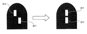
図9は、実施例1の無散瞳眼底カメラにてオートON/OFFスイッチをONにしての自動眼底撮影時におけるオートフォーカス作用を説明するスプリット輝線図である。図10は、実施例1の無散瞳眼底カメラにてオートON/OFFスイッチをONにしての自動眼底撮影時におけるオートフォーカス動作でのスプリット輝線の重心位置検出作用の説明図である。以下、例えば、検者が未熟者であり、オート撮影モードにより眼底撮影を行う場合のオートフォーカス動作手順を説明する。
[Auto focus function]
FIG. 9 is a split bright line diagram for explaining the autofocus operation during automatic fundus photographing with the auto-ON / OFF switch turned on in the non-mydriatic fundus camera of the first embodiment. FIG. 10 is an explanatory view of the center position detection operation of the split bright line in the autofocus operation at the time of automatic fundus photographing with the auto-ON / OFF switch turned on in the non-mydriatic fundus camera of the first embodiment. Hereinafter, for example, an autofocus operation procedure when the examiner is immature and the fundus imaging is performed in the auto imaging mode will be described.
まず、オート撮影モードでのオートフォーカス動作とは、合焦ハンドル3aに対する手動操作に代え、オートフォーカスモータ332の駆動により、図9に示すように、離れている2つのスプリット輝線311,311を垂直に揃える動作をいう。
First, the autofocus operation in the auto shooting mode is not manually operated with respect to the focusing
電源スイッチを入れ、オートON/OFFスイッチ213をONにし、前眼部撮影から眼底撮影に切り換えられると、図6のフローチャートにおいて、ステップS1→ステップS2→ステップS3→ステップS4へと進む。ステップS3では、キャプチャボード319を介して観察用CCDカメラ37のCCD37aからの眼底観察像を1フレーム分だけボードPC316に取り込む。次のステップS4では、オートフォーカスのためのスプリット輝線311,311の重心位置を検出する。
When the power switch is turned on and the auto ON /
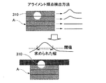
ここで、スプリット輝線311,311の重心位置の検出について説明する。図10の左側に示すように、取り込まれた眼底観察像中のスプリット輝線311,311と同じ程度の高さでスプリット輝線311,311より広い幅の領域A1,A2を設定する。そして、図10の右側に示すように、領域A1,A2のそれぞれの輝度分布特性において、輝度が閾値以上である領域の中心点を重心位置として検出するようにしている。
Here, detection of the position of the center of gravity of the split
そして、スプリット輝線311,311の重心位置が検出された数が2つである、つまり、スプリット輝線311,311の数が2つであると判断された場合は、図6のフローチャートにおいて、ステップS4からステップS5→ステップS6→ステップS7→ステップS8→ステップS9へと進む。ステップS6では、2つのスプリット輝線311,311の重心位置の差を算出し(図10)、オートフォーカスモータ332によるモータ移動量を確定する。ステップS7では、確定したモータ移動量とモータ移動方向にてオートフォーカスモータ332を駆動する。ステップS8では、再度、眼底観察像を1フレーム分だけ取り込み、2つのスプリット輝線311,311のズレが認識される場合、一致させる方向にオートフォーカスモータ332を用いて微調整する。ステップS9では、2つのスプリット輝線311,311の位置が合焦範囲内であるか否かを判断する。
When it is determined that the number of the center of gravity positions of the split
そして、ステップS9にて、合焦範囲内と判断された場合は、ステップS10→ステップS11へ進み、ステップS11では、合焦が完了したとし、次の小瞳孔検知動作やオートシュート機能動作を開始する。また、ステップS9にて、合焦範囲外と判断された場合は、ステップS3へ戻り、上記オートフォーカス動作を合焦範囲内と判断されるまで繰り返す。 If it is determined in step S9 that it is within the in-focus range, the process proceeds from step S10 to step S11. In step S11, it is determined that the in-focus state has been completed, and the next small pupil detection operation or autoshoot function operation is started. To do. If it is determined in step S9 that it is out of focus range, the process returns to step S3, and the above autofocus operation is repeated until it is determined that it is within focus range.
一方、そして、スプリット輝線311,311の重心位置が検出された数が1つである、つまり、スプリット輝線311,311の数が1つであると判断された場合は、図6のフローチャートにおいて、ステップS4からステップS5→ステップS12→ステップS13→ステップS14→ステップS15へと進む。ステップS12では、スプリット輝線311,311の数が1つかゼロかを判断する。ステップS13では、1つのスプリット輝線311の重心位置と、予め設定されている走査線の合焦位置との差を算出する。ステップS14では、確定した差に基づく移動量と移動方向により、オートフォーカスモータ332を駆動する。ステップS15では、再度、眼底観察像を1フレーム分だけ取り込み、観察像にて認識されるスプリット輝線311,311が2つ有るか否かを判断する。
On the other hand, when it is determined that the number of the center of gravity positions of the split
そして、ステップS15に至った時点において、スプリット輝線311,311が2つ存在すると判断された場合は、ステップS6へ進み、2つのスプリット輝線311,311に基づくオートフォーカス動作を改めて実行する。これは、1つのみの合焦では、誤差が大きいためであり、ステップS15にてスプリット輝線311,311が2つ存在しないかどうかを再度確認し、2つ存在が確認された場合は、合焦誤差を小さく抑える手法(ステップS6〜ステップS8)を実行する。
When it is determined that there are two split
なお、ステップS15において、スプリット輝線311,311が、やはり1つしか存在しないと判断されると、ステップS11へ進み、合焦が完了したとの判断に基づき、次の小瞳孔検知動作やオートシュート機能動作を開始する。
If it is determined in step S15 that there is only one split
[2つのスプリット輝線認識時におけるオートシュート作用]
図11は、実施例1の無散瞳眼底カメラにてオートON/OFFスイッチをONにしての自動眼底撮影時におけるアライメント輝点状態の分類図であり、(a)は()スケール内に輝点がない状態を示し、(b)は()スケール内に1つの輝点のみがある状態を示し、(c)は()スケール内に2つの離れた輝点がある状態を示し、(d)は()スケール内に2つの合致していない輝点がある状態を示し、(e)は()スケール内に2つの合致した輝点がある状態を示す。図12は、実施例1の無散瞳眼底カメラにてオートON/OFFスイッチをONにしての自動眼底撮影時におけるオートアライメント動作でのアライメント輝点の検出領域の設定作用説明図である。図13は、実施例1の無散瞳眼底カメラにてオートON/OFFスイッチをONにしての自動眼底撮影時におけるオートアライメント動作でのアライメント輝点の重心位置検出作用の説明図である。以下、上記オートフォーカス動作に引き続き実行される2つのスプリット輝線認識時におけるオートシュート動作手順を説明する。
[Auto-shoot action when recognizing two split lines]
FIG. 11 is a classification diagram of alignment bright spot states at the time of automatic fundus photographing with the auto-ON / OFF switch turned on in the non-mydriatic fundus camera of the first embodiment. (B) shows the state with only one bright spot in the scale (), (c) shows the state with two separate bright spots in the scale (d) ) Shows a state where there are two unmatched bright spots in the scale (), and (e) shows a state where there are two matched bright spots in the scale (). FIG. 12 is an explanatory diagram of the setting operation of the detection region of the alignment bright spot in the automatic alignment operation at the time of automatic fundus photographing with the auto ON / OFF switch turned on in the non-mydriatic fundus camera of the first embodiment. FIG. 13 is an explanatory diagram of the center-of-gravity position detection operation of the alignment bright spot in the automatic alignment operation at the time of automatic fundus photographing with the auto-ON / OFF switch turned on in the non-mydriatic fundus camera of the first embodiment. Hereinafter, an auto-shoot operation procedure when recognizing two split bright lines that is executed following the auto-focus operation will be described.
まず、オート撮影モードでのオートシュート動作とは、モータ駆動制御によるオートフォーカス動作とオートアライメント動作による引き続き、合焦条件とアライメント整合条件の成立を確認すると、自動的にフラッシュを発光させて眼底撮影を行う動作をいう。 First of all, auto-shooting in auto-shooting mode means auto-focusing and auto-alignment by motor drive control. When the focus condition and alignment-matching condition are confirmed, the flash is automatically emitted and the fundus is shot. This is the operation to perform.
オートフォーカス動作により図6のステップS11にて合焦完了であると判定され、かつ、2つのスプリット輝線311,311が認識されている時には、図7のフローチャートにおいて、ステップS16→ステップS17→ステップS25→ステップS26→ステップS27へと進む。ステップS16では、2つのアライメント輝点310,310の重心位置を検出する。ステップS17では、スプリット輝線311,311が1つ以下か否かが判断される。ステップS25では、ステップS17でのスプリット輝線311,311が2つとの判断にしたがって、2つのアライメント輝点310,310の重心位置の差を算出し、アライメントモータ330によるモータ移動量を確定する。ステップS26では、確定したモータ移動量とモータ移動方向にてアライメントモータ330を駆動する。ステップS27では、2つのアライメント輝点310,310が()スケール309内にて合致しているか否かを判断する。
When it is determined that the focusing is completed in step S11 of FIG. 6 by the autofocus operation and the two split
ここで、ステップS16でのアライメント輝点310,310の重心位置検出について説明する。まず、アライメント輝点310,310の位置は、図11に示すように、()スケール309内に輝点がない状態(図11(a))、()スケール309内に1つの輝点のみがある状態(図11(b))、()スケール309内に2つの離れた輝点がある状態(図11(c))、()スケール309内に2つの合致していない輝点がある状態(図11(d))、()スケール309内に2つの合致した輝点がある状態(図11(e))、に分類される。
Here, the center-of-gravity position detection of the alignment
そして、アライメント輝点310,310の検出領域は、図12に示すように、()スケール309内のアライメント輝点310,310を検出するための領域A(横幅aと縦幅cで囲まれる領域)と、()スケール309内にアライメント輝点310,310を検出した場合、()スケール309外にもアライメント輝点310があるか検出するための領域B(横幅bと縦幅cで囲まれる領域)に分かれる。なお、領域Bは、領域A内にアライメント輝点310,310が検出されたとき以外は使用しない。
As shown in FIG. 12, the detection region of the alignment
アライメント輝点310,310の検出方法は、図13に示すように、領域Aを3本の横線により縦方向に4分割する。分割した領域毎に、縦方向に画素値を積算すると、4本の波形が得られる。得られた波形に対して、設定された閾値以上になる部分の幅を求める。4本の波形に対して得られた幅で、最も長いものをアライメント輝点310の幅とする。算出された幅に対して範囲を設け、その幅が範囲以内にあれば、その分割領域をアライメント輝点310の位置とする。最大の幅が算出された分割領域の部分のみ、図12に示す領域Bに拡張して、同様にアライメント輝点310の検出を行う。領域Bでアライメント輝点310が検出されなければ、()スケール309内にアライメント輝点310が一つとなり、2つのアライメント輝点310,310が合致しているとみなす。
As shown in FIG. 13, the method of detecting the alignment
ステップS25においては、2つのアライメント輝点310,310の()スケール309に対する位置関係により、モータ移動量と共にモータ移動方向(上下・左右・前後)も確定しておく。そして、ステップS26では、ステップS25で確定したモータ移動量とモータ移動方向にてアライメントモータ330を駆動する。そして、ステップS27にて、2つのアライメント輝点310,310が()スケール309内にて合致していないと判断された場合は、図7のフローチャートにおいて、ステップS16→ステップS17→ステップS25→ステップS26→ステップS27へと進む流れを繰り返す。
In step S25, the motor movement direction (up / down / left / right / front / rear) is determined together with the motor movement amount based on the positional relationship between the two alignment
そして、ステップS27にて2つのアライメント輝点310,310が()スケール309内にて合致していると判断された場合には、ステップS28へ進み、スプリット輝線311,311の状況の最終確認を終了したか否かを判断する。このステップS28にてスプリット輝線311,311の最終確認が未終了(2つの輝線位置が合焦範囲外)と判断された場合には、ステップS3へ戻り、再度、オートフォーカス動作を実行する。
If it is determined in step S27 that the two alignment
一方、ステップS28にてスプリット輝線311,311の最終確認が終了(2つの輝線位置が合焦範囲内)と判断された場合には、ステップS29へ進み、ステップS29では、自動的にキセノンランプ17aを発光させながらシャッターを切り、オートシュート機能による眼底撮影動作を行い、スタートへ戻る。
On the other hand, if it is determined in step S28 that the final confirmation of the split
すなわち、オートシュート機能は、2つのアライメント輝点310,310の合致を検出した後、オートフォーカスが終了し、瞬きがない状態であれば、撮影スイッチ2cを押さなくても、自動的にキセノンランプ17aを発光させながらシャッターを切り、眼底撮影を行う動作により達成される。
In other words, the auto-shoot function automatically detects the coincidence of the two alignment
なお、オートシュート動作は、
1)フォーカス状態
オートフォーカスにて精度が±0.5D以内
2)アライメント状態
被検眼上XY方向が0.5mm以内で、被検眼上Z方向が0.3mm以内
上記1),2)を満たすことを実行条件とする。
The auto-shoot operation is
1) Focus state Accuracy within ± 0.5D with auto focus
2) Alignment state It is assumed that the above conditions 1) and 2) are satisfied when the XY direction on the eye to be examined is within 0.5 mm and the Z direction on the eye to be examined is within 0.3 mm.
[小瞳孔判定時におけるオートシュート作用]
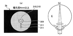
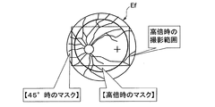
図14は、実施例1の無散瞳眼底カメラにて観察モニタ3bに2つのスプリット輝線が映し出される状態の説明図であり、(a)は被検眼Eの瞳孔径が4mm以上でアライメント輝点が合致している場合のモニタ観察像を示し、(b)は被検眼Eの瞳孔径が4mm以上でアライメント輝点が合致している場合の瞳孔への入射光を示す。図15は、実施例1の無散瞳眼底カメラにて観察モニタ3bに1つだけスプリット輝線が映し出される状態の説明図であり、(a)は被検眼Eの瞳孔径が4mm以内でアライメント輝点が合致している場合のモニタ観察像を示し、(b)はアライメント輝点が合致していない場合の瞳孔への入射光を示す。図16は、実施例1の無散瞳眼底カメラにて小瞳孔判定時における小瞳孔絞り(水晶体絞り)と電気的なマスクの挿入作用を説明するための眼底像を示す図である。
[Auto-shoot action when determining small pupils]
FIG. 14 is an explanatory diagram of a state in which two split bright lines are projected on the
まず、オート撮影モードでの小瞳孔撮影機能とは、被検眼Eが小瞳孔の場合であっても自動的にフラッシュを発光させて眼底撮影を行うオートシュート動作を達成するため、小瞳孔判定時に自動的に小瞳孔絞りを入れる機能をいう。 First, the small pupil photographing function in the auto photographing mode is an auto-shooting operation in which the fundus photographing is performed by automatically emitting a flash even when the eye E is a small pupil. This is a function that automatically turns the small pupil aperture.
例えば、被検眼Eが小瞳孔であって、観察モニタ3bに1つだけしかスプリット輝線311が映し出されない場合には、図7のフローチャートにおいて、ステップS17からステップS18→ステップS19→ステップS20へと進む。ステップS18では、観察像にて認識されるスプリット輝線311,311が1つ、あるいは、ゼロのいずれかであるかが判断される。ステップS19では、ステップS18でのスプリット輝線311,311が1つであるとの判断に続き、2つのアライメント輝点310,310が規定の位置、つまり、()スケール309の内側に存在するか否かを判断する。ステップS20では、ステップS19での2つのアライメント輝点310,310が規定位置内であるとの判断に続き、小瞳孔絞り(水晶体絞り)を挿入する。
For example, when the eye E is a small pupil and only one split
すなわち、被検眼Eの瞳孔径が4mm以上でアライメント輝点310,310が合致している場合には、図14(b)に示すように、被検眼Eの瞳孔を経過してアライメント輝点310,310を形成する2つの光が入射される。このため、図14(a)に示すように、観察モニタ3bに2つのスプリット輝線311,311が映し出される。
That is, when the pupil diameter of the eye E is 4 mm or more and the alignment
これに対し、2つのアライメント輝点310,310が合致しているが、被検眼Eの瞳孔径が4mm以内の小瞳孔の場合には、被検眼Eの瞳孔を経過してアライメント輝点310,310を形成する2つの光の同時入射を行えないため、図15(a)に示すように、観察モニタ3bに1つだけスプリット輝線311が映し出される。また、被検眼Eの瞳孔径にかかわらず、アライメント輝点310,310が合致していない場合には、図15(b)に示すように、被検眼Eの瞳孔を経過してアライメント輝点310を形成する1つの光のみが入射されるため、図15(a)に示すように、観察モニタ3bに1つだけスプリット輝線311が映し出される。
On the other hand, the two alignment
したがって、観察モニタ3bに1つだけしかスプリット輝線311が映し出されないスプリット輝線条件と、2つのアライメント輝点310,310が合致しているアライメント輝点合致条件が共に成立した場合には、被検眼Eの瞳孔径が4mm以内の小瞳孔であると判定することができる。
Therefore, when both the split bright line condition in which only one split
このように、小瞳孔であると判定された場合には、瞳孔径が4mm以上であることを基準として決めた光量であると、眼底への入射光が強すぎ、フレアー等を生じて鮮明な眼底像の撮影ができない。このため、眼底へ到達する光量を抑えるように絞った小瞳孔絞り(水晶体絞り)を自動的に挿入することで、鮮明な眼底像の撮影ができるようにする。 As described above, when it is determined that the pupil is a small pupil, if the amount of light is determined based on the pupil diameter being 4 mm or more, the incident light to the fundus is too strong, causing flare and the like. The fundus image cannot be taken. For this reason, a sharp pupil image can be captured by automatically inserting a small pupil diaphragm (crystal diaphragm) that is squeezed so as to suppress the amount of light reaching the fundus.
例えば、高倍時(画角30°)に水晶体絞りを切り換えることで、φ3.3mmの瞳径まで撮影できるようにする。そして、高倍時には、水晶体絞りを切り換えると共に、フレアー対策として、図16に示すように、太実線リングで示す範囲に高倍時の電気的マスクを入れる。なお、図16には、高倍時の電気的マスクと共に、長方形による高倍時の撮影範囲と、画角45°時の細線リングで示す範囲の電気的マスクを併せて示す。
For example, by switching the lens aperture at high magnification (angle of
そして、ステップS20にて小瞳孔絞りを挿入した後は、ステップS25→ステップS26→ステップS27へと進み、被検眼Eが小瞳孔であっても、撮影スイッチ2cを押さなくても、自動的にキセノンランプ17aを発光させながらシャッターを切り、眼底撮影を行うオートシュート機能が達成される。
Then, after inserting the small pupil stop in step S20, the process proceeds from step S25 to step S26 to step S27, and even if the eye E is a small pupil, even if the photographing
[スプリット輝線誘導作用]
例えば、被検眼Eが小瞳孔であって、観察モニタ3bに全くスプリット輝線が映し出されない場合には、少なくとも1つのスプリット輝線311を用いて行われるオートフォーカス動作を実行することができず、オートシュート機能が発揮されない。
[Split emission line induction effect]
For example, when the eye E is a small pupil and no split bright line is projected on the
したがって、被検眼Eが小瞳孔であって、観察モニタ3bに全くスプリット輝線が映し出されない場合には、図7のフローチャートにおいて、ステップS17からステップS18→ステップS21へと進む。ステップS21では、ステップS18でのスプリット輝線311,311がゼロであるとの判断に続き、ステップS20と同様に、小瞳孔絞り(水晶体絞り)を挿入する。つまり、観察モニタ3bに全くスプリット輝線が映し出されない場合には、被検眼Eの瞳孔径が4mm以内の小瞳孔であると推定することができるため、小瞳孔判定時と同様に、小瞳孔絞り(水晶体絞り)を挿入する。
Therefore, when the eye E is a small pupil and no split bright line is projected on the
次のステップS22では、撮影眼は右眼であるか左眼であるかが判断され、左眼であると判断された場合にはステップS23へ進み、左眼でスプリット輝線311,311が1つでも入るように検者に対してアライメントを変更する誘導指示を表示し、ステップS3へ進む。ここで、誘導指示の表示は、()スケール309を被検者の左眼上で0.5mm相当分ずらすことにより行う。
In the next step S22, it is determined whether the photographed eye is the right eye or the left eye. If it is determined that the photographing eye is the left eye, the process proceeds to step S23, and even one split
また、右眼であると判断された場合にはステップS24へ進み、右眼でスプリット輝線311,311が1つでも入るように検者に対してアライメントを変更する誘導指示を表示し、ステップS3へ進む。ここで、誘導指示の表示は、()スケール309を被検者の右眼上で0.5mm相当分ずらすことにより行う。
If it is determined that the eye is the right eye, the process proceeds to step S24, and a guidance instruction to change the alignment is displayed to the examiner so that at least one split
したがって、被検眼Eが小瞳孔であって、観察モニタ3bに全くスプリット輝線が映し出されない場合であっても、スプリット輝線誘導動作により、少なくとも1つのスプリット輝線311が観察モニタ3bに映し出されるように検者に対し誘導指示が行われる。このため、オート撮影モードにより眼底撮影を行う場合、()スケール309のズレを見た検者が、被検者に対するアライメントが正規位置となるように修正変更することで、少なくとも1つのスプリット輝線311が観察モニタ3bに映し出されるようになり、1つまたは2つのスプリット輝線311,311を用いて行われるオートフォーカス動作の実行が確保され、検者が意図するオートシュート機能を発揮することができる。
Accordingly, even when the eye E is a small pupil and no split bright line is displayed on the
次に、効果を説明する。
実施例1の無散瞳眼底カメラにあっては、下記に列挙する効果を得ることができる。
Next, the effect will be described.
In the non-mydriatic fundus camera of the first embodiment, the effects listed below can be obtained.
(1) 被検眼Eの撮影対象部分に合焦するためスプリット輝線311,311を投影するスプリット光学系60と、被検眼Eに対して装置本体3を位置合わせするためアライメント輝点310,310を投影するアライメント系40と、前記被検眼Eの撮影対象像を前記スプリット輝線311,311および前記アライメント輝点310,310と共に表示する観察モニタ3bを含む観察光学系30と、前記被検眼Eの撮影対象像を撮影する撮影用CCDカメラ6を含む撮影光学系20と、を備えた無散瞳眼底カメラにおいて、前記観察光学系30に撮影対象部分と共に表示されるスプリット輝線311,311の位置認識に基づき、被検眼Eの撮影対象部分に合焦させるフォーカス動作と、前記観察光学系30に撮影対象部分と共に表示されるアライメント輝点310,310の位置認識に基づき、被検眼Eに対して装置本体3を位置合わせするアライメント動作を行い、合焦と位置合わせの最終確認結果が適正範囲内になると、自動フラッシュ撮影動作を実行する自動撮影制御手段(図6及び図7)を設けた。このため、合焦とアライメント調整の操作負担を軽減し、観察画面が不規則に変化することなく、自動撮影を開始してから応答良く自動フラッシュ撮影動作を実行することができる。
(1) A split
(2) 前記自動撮影制御手段(図6及び図7)は、前記観察光学系30の観察映像信号により認識されるスプリット輝線311,311の位置検出に基づき、被検眼Eの撮影対象部分に合焦させるオートフォーカス動作制御を行うオートフォーカス動作制御部(ステップS3〜ステップS15)と、前記オートフォーカス動作制御により適正範囲内の合焦であると確認すると、前記観察光学系30の観察映像信号により認識されるアライメント輝点310,310の位置検出に基づき、被検眼Eに対して装置本体3を位置合わせするオートアライメント動作制御を行うオートアライメント動作制御部(ステップS16,ステップS25,ステップS26)と、前記オートアライメント動作制御により適正範囲内の位置合わせであると確認した後、合焦の最終確認を行い、この合焦の最終確認結果が適正範囲外であれば、オートフォーカス動作制御とオートアライメント動作制御による組み合わせ動作制御を繰り返し、合焦の最終確認結果が適正範囲内になると、自動フラッシュ撮影動作を行うオートシュート動作制御部(ステップS27〜ステップS29)と、を有する。このため、合焦とアライメント調整の操作負担を解消できると共に、最終確認結果が適正範囲外のとき、オートフォーカス動作制御とオートアライメント動作制御が連続する組み合わせ動作制御により、オートフォーカス動作制御とオートアライメント動作制御をそれぞれ独立に行う場合に比べ、応答良く短時間にて最終確認結果を適正範囲内に収束させることができる。
(2) The automatic photographing control means (FIGS. 6 and 7) focuses on the photographing target portion of the eye E based on the position detection of the split
(3) 前記自動撮影制御手段(図6及び図7)は、前記観察光学系30の観察映像信号により認識されるスプリット輝線311が1つであるというスプリット視標条件(ステップS18で1つの場合)と、2つのアライメント輝点310,310が規定の範囲内にあるというアライメント合致条件(ステップS19でYES)が共に成立すると、被検眼Eが小瞳孔であると判定し、自動フラッシュ撮影動作を行う前、自動的に小瞳孔絞りを挿入する小瞳孔絞り挿入制御部(ステップS20)を有する。このため、被検者が小瞳孔であっても、自動的に小瞳孔絞りが挿入されることで、小瞳孔の被検者も自動撮影の対象に含めることができる。
(3) The automatic photographing control means (FIG. 6 and FIG. 7) is configured so that the split target condition that there is one split
(4) 前記自動撮影制御手段(図6及び図7)は、前記観察光学系30の観察映像信号により認識されるスプリット輝線311,311がゼロである場合、撮影眼が右眼か左眼に応じ、少なくとも1つのスプリット輝線311が前記観察光学系30の観察映像信号により認識されるように検者に対し誘導指示を行うスプリット視標誘導制御部(ステップS22〜ステップS24)を有する。このため、小瞳孔やアライメントの位置ズレ等により、観察光学系30の観察映像信号により認識されるスプリット輝線311,311がゼロである場合であっても、オートフォーカス動作制御に最小限必要な1つのスプリット輝線311を認識できる状態に誘導することで、確実に自動フラッシュ撮影動作を実行することができる。
(4) When the split
(5) 前記オートフォーカス動作制御部は、前記観察モニタ3bの観察像を取り込み(ステップS3)、取り込んだ観察像に2つのスプリット輝線311,311が認識される場合(ステップS5で2つの場合)、2つのスプリット輝線311,311の重心位置を検出し、2つのスプリット視標の重心位置の差を算出し(ステップS6)、算出した重心位置の差をゼロとする合焦レンズ移動量を得る制御指令をオートフォーカスアクチュエータ(オートフォーカスモータ332)に出力する(ステップS7)。このため、手動による合焦操作で2つのスプリット輝線311,311を完全に揃えるレベルで、精度良くオートフォーカス動作制御を行うことができる。
(5) The autofocus operation control unit captures an observation image of the
(6) 前記オートフォーカス動作制御部は、前記観察モニタ3bの観察像を取り込み(ステップS3)、取り込んだ観察像に1つのスプリット輝線311が認識される場合(ステップS5で1つの場合)、1つのスプリット輝線311の重心位置を検出し、1つのスプリット視標の重心位置と予め設定されている合焦位置の差を算出し(ステップS13)、算出した差をゼロとする合焦レンズ移動量を得る制御指令をオートフォーカスアクチュエータ(オートフォーカスモータ332)に出力する(ステップS14)。このため、小瞳孔やアライメントの位置ズレ等により、取り込んだ観察像に1つのスプリット輝線311のみが認識される場合であっても、良好な精度によりオートフォーカス動作制御を行うことができる。
(6) The autofocus operation control unit captures an observation image of the
(7) 前記オートアライメント動作制御部は、前記観察モニタ3bの観察像を取り込み、取り込んだ観察像にて認識される2つのアライメント輝点310,310の重心位置を検出し(ステップS16)、2つのアライメント輝点310,310の重心位置と予め設定されているアライメント調整位置(()スケール309の中心位置)の差を算出し(ステップS25)、2つのアライメント輝点310,310の重心位置がアライメント調整位置に合致するアライメント移動量を得る制御指令をアライメントアクチュエータ(アライメントモータ330)に出力する(ステップS26)。このため、手動によるアライメント調整操作で2つのアライメント輝点310,310を()スケール309の中心位置に合致させるレベルで、精度良くオートアライメント動作制御を行うことができる。
(7) The auto alignment operation control unit captures the observation image of the
(8) 被検眼Eの眼底Efを手動フラッシュ撮影するマニュアル撮影モードと、被検眼Eの眼底Efを自動フラッシュ撮影するオート撮影モードを選択するオートON/OFFスイッチ213を設け、前記自動撮影制御手段(図6及び図7)は、前記オートON/OFFスイッチ213がONである条件(ステップS1)と、前眼部から眼底への切り換わり条件(ステップS2)とが共に成立することを、オート撮影モードでの制御動作開始条件とした。このため、検者の熟練レベルや好みに応じてマニュアル撮影モードとオート撮影モードを選択することができると共に、意図しない連続撮影を防止することができる。
なお、連続撮影の防止は、オートON/OFFスイッチ213をONにして被検眼Eの眼底Efを自動フラッシュ撮影した後、一度、眼底Efから前眼部に引く動作を行わないと、次のオート撮影モードに入らないようにしたことにより達成される。
(8) An automatic ON /
In order to prevent continuous shooting, the auto ON /
以上、本発明の眼科撮影装置を実施例1に基づき説明してきたが、具体的な構成については、この実施例1に限られるものではなく、特許請求の範囲の各請求項に係る発明の要旨を逸脱しない限り、設計の変更や追加等は許容される。 As described above, the ophthalmologic photographing apparatus of the present invention has been described based on the first embodiment. However, the specific configuration is not limited to the first embodiment, and the gist of the invention according to each claim of the claims. As long as they do not deviate, design changes and additions are permitted.
実施例1では、自動撮影制御手段として、観察映像信号により認識されるスプリット輝線311,311の位置検出に基づき、被検眼Eの撮影対象部分に合焦させるオートフォーカス動作と、観察映像信号により認識されるアライメント輝点310,310の位置検出に基づき、被検眼Eに対して装置本体3を位置合わせするオートアライメント動作を行い、合焦と位置合わせの最終確認結果が適正範囲内になると、自動フラッシュ撮影動作を実行する例を示した。しかし、フォーカス動作とアライメント動作の少なくとも一方をマニュアル操作により行い、合焦と位置合わせの最終確認結果が適正範囲内になると、自動フラッシュ撮影動作を実行するようなオートシュート動作機能のみ有するものであっても良い。
In the first embodiment, the automatic photographing control means is recognized based on the detection of the position of the split
実施例1では、スプリット視標として方形状の2つのスプリット輝線311,311を用い、2つのスプリット輝線311,311を縦方向に揃えた状態を合焦状態とする例を示した。しかし、スプリット視標としては、方形以外の様々な形状としても良い。さらに、複数のスプリット視標を横方向に揃えた状態を合焦状態とする例であっても良い。
In the first embodiment, two square split
実施例1では、アライメント視標として円形状の2つのアライメント輝点310,310を用い、2つのアライメント輝点310,310を()スケール309の中心位置に合致させた状態をアライメント調整状態とする例を示した。しかし、アライメント視標としては、円形以外の様々な形状としても良い。さらに、()スケール309以外の形状を持つスケール表示の外周位置に複数のアライメント視標を一致させた状態をアライメント調整状態とする例であっても良い。
In the first embodiment, two circular alignment
実施例1では、オートフォーカス動作制御を先行し、続いてオートアライメント動作制御を行う例を示した。しかし、オートアライメント動作制御を先行し、続いてオートフォーカス動作制御を行う例としても良い。さらに、オートアライメント動作制御とオートフォーカス動作制御を同時進行による制御にて行うような例であっても良い。 In the first embodiment, the example in which the auto focus operation control is preceded and the auto alignment operation control is subsequently performed is shown. However, an example in which auto-alignment operation control is preceded and then auto-focus operation control is performed may be used. Furthermore, an example in which auto alignment operation control and auto focus operation control are performed by simultaneous progress control may be used.
実施例1では、眼科撮影装置の一例である無散瞳眼底カメラへの適用例を示したが、合焦操作とアライメント調整操作を要する他の眼科撮影装置に対しても適用することができる。要するに、スプリット光学系とアライメント系と観察光学系と撮影光学系を備えた眼科撮影装置であれば適用できる。 In the first embodiment, an example of application to a non-mydriatic fundus camera, which is an example of an ophthalmologic photographing apparatus, is shown. However, the present invention can also be applied to other ophthalmic photographing apparatuses that require a focusing operation and an alignment adjustment operation. In short, any ophthalmologic photographing apparatus having a split optical system, an alignment system, an observation optical system, and a photographing optical system can be applied.
1 装置ベース
2 架台部
2a 操作パネル
2b ジョイスティック
2c 撮影スイッチ
209 小瞳孔スイッチ
213 オートON/OFFスイッチ
3 装置本体
3a 合焦ハンドル
3b 観察モニタ
31 観察LCDユニット
37 観察用CCDカメラ
309 ()スケール
310,310 アライメント輝点(アライメント視標)
311,311 スプリット輝線(スプリット視標)
313 小瞳孔絞り
315 本体PCB
316 ボードPC
317 撮影カメラ中継PCB
318 DC電源PCB
319 キャプチャボード
324 アライメントモータ検知センサ
326 オートフォーカスモータ(+)検知センサ
327 オートフォーカスモータ(-)検知センサ
330 アライメントモータ(アライメントアクチュエータ)
332 オートフォーカスモータ(オートフォーカスアクチュエータ)
333 水晶体絞り駆動ソレノイド
334 前眼部切換え駆動ソレノイド
335 反射棒駆動ソレノイド
4 顎受け
5 外部固視標
6 撮影用CCDカメラ(カメラ)
7 マウス/10キーボード
8 プリンタ
9 パーソナルコンピュータ
9a PC用モニタ
10 照明光学系
17a キセノンランプ
17b ハロゲンランプ
20 撮影光学系
30 観察光学系
40 アライメント系
41 アライメントLED
50 内部固視系
60 スプリット光学系
61 スプリットLED
E 被検眼
Ef 眼底(撮影対象)
DESCRIPTION OF
209 Pupil switch
213 Auto ON /
309 () scale
310,310 Alignment bright spot (alignment target)
311,311 Split line (split target)
313 Small pupil diaphragm
315 PCB
316 board PC
317 Shooting Camera Relay PCB
318 DC power PCB
319 capture board
324 Alignment motor detection sensor
326 Autofocus motor (+) detection sensor
327 Autofocus motor (-) detection sensor
330 Alignment motor (alignment actuator)
332 Autofocus motor (Autofocus actuator)
333 Lens drive solenoid
334 Anterior segment switching drive solenoid
335 Reflector drive solenoid 4
7 mouse / 10
50
E Eye to be examined
Ef fundus (target)
Claims (9)
前記観察光学系に撮影対象部分と共に表示されるスプリット視標の位置認識に基づき、被検眼の撮影対象部分に合焦させるフォーカス動作と、前記観察光学系に撮影対象部分と共に表示されるアライメント視標の位置認識に基づき、被検眼に対して装置本体を位置合わせするアライメント動作を行い、合焦と位置合わせの最終確認結果が適正範囲内になると、自動フラッシュ撮影動作を実行する自動撮影制御手段を設け、
前記自動撮影制御手段は、前記観察光学系の観察映像信号により認識されるスプリット視標が1つであるというスプリット視標条件と、2つのアライメント視標が規定の範囲内にあるというアライメント合致条件が共に成立すると、被検眼が小瞳孔であると判定し、自動フラッシュ撮影動作を行う前、自動的に小瞳孔絞りを挿入する小瞳孔絞り挿入制御部を有する
ことを特徴とする眼科撮影装置。 A split optical system for projecting a split target to focus on an imaging target portion of the eye to be examined, an alignment system for projecting an alignment target for aligning the apparatus main body with respect to the eye to be examined, and an imaging target for the eye to be examined In an ophthalmologic photographing apparatus comprising: an observation optical system including an observation monitor that displays an image together with the split target and the alignment target; and a photographing optical system including a camera that captures a photographing target image of the eye to be examined;
Based on the position recognition of the split target displayed together with the imaging target part on the observation optical system, a focus operation for focusing on the imaging target part of the eye to be inspected, and the alignment target displayed together with the imaging target part on the observation optical system Based on the position recognition, an alignment operation for aligning the apparatus main body with respect to the eye to be examined is performed, and when the final confirmation result of focusing and alignment is within an appropriate range, an automatic imaging control means for executing an automatic flash imaging operation is provided. Provided ,
The automatic photographing control means includes a split target condition that one split target is recognized by an observation video signal of the observation optical system and an alignment matching condition that two alignment targets are within a specified range. If both are established , the ophthalmic imaging apparatus has a small pupil aperture insertion control unit that determines that the subject's eye is a small pupil and automatically inserts the small pupil aperture before performing the automatic flash imaging operation .
前記観察光学系に撮影対象部分と共に表示されるスプリット視標の位置認識に基づき、被検眼の撮影対象部分に合焦させるフォーカス動作と、前記観察光学系に撮影対象部分と共に表示されるアライメント視標の位置認識に基づき、被検眼に対して装置本体を位置合わせするアライメント動作を行い、合焦と位置合わせの最終確認結果が適正範囲内になると、自動フラッシュ撮影動作を実行する自動撮影制御手段を設け、
前記自動撮影制御手段は、前記観察光学系の観察映像信号により認識されるスプリット視標がゼロである場合、撮影眼が右眼か左眼に応じ、少なくとも1つのスプリット視標が前記観察光学系の観察映像信号により認識されるように検者に対し誘導指示を行うスプリット視標誘導制御部を有する
ことを特徴とする眼科撮影装置。 A split optical system for projecting a split target to focus on an imaging target portion of the eye to be examined, an alignment system for projecting an alignment target for aligning the apparatus main body with respect to the eye to be examined, and an imaging target for the eye to be examined In an ophthalmologic photographing apparatus comprising: an observation optical system including an observation monitor that displays an image together with the split target and the alignment target; and a photographing optical system including a camera that captures a photographing target image of the eye to be examined;
Based on the position recognition of the split target displayed together with the imaging target part on the observation optical system, a focus operation for focusing on the imaging target part of the eye to be inspected, and the alignment target displayed together with the imaging target part on the observation optical system Based on the position recognition, an alignment operation for aligning the apparatus main body with respect to the eye to be examined is performed, and when the final confirmation result of focusing and alignment is within an appropriate range, an automatic imaging control means for executing an automatic flash imaging operation is provided. Provided ,
When the split target recognized by the observation video signal of the observation optical system is zero, the automatic photographing control means determines whether the photographing eye is a right eye or a left eye, and at least one split target is the observation optical system. An ophthalmologic photographing apparatus comprising: a split target guidance control unit for instructing an examiner to be recognized by the observation video signal .
前記観察光学系に撮影対象部分と共に表示されるスプリット視標の位置認識に基づき、被検眼の撮影対象部分に合焦させるフォーカス動作と、前記観察光学系に撮影対象部分と共に表示されるアライメント視標の位置認識に基づき、被検眼に対して装置本体を位置合わせするアライメント動作を行い、合焦と位置合わせの最終確認結果が適正範囲内になると、自動フラッシュ撮影動作を実行する自動撮影制御手段を設け、
前記自動撮影制御手段は、
前記観察光学系の観察映像信号により認識されるスプリット視標が1つであるというスプリット視標条件と、2つのアライメント視標が規定の範囲内にあるというアライメント合致条件が共に成立すると、被検眼が小瞳孔であると判定し、自動フラッシュ撮影動作を行う前、自動的に小瞳孔絞りを挿入する小瞳孔絞り挿入制御部と、
前記観察光学系の観察映像信号により認識されるスプリット視標がゼロである場合、撮影眼が右眼か左眼に応じ、少なくとも1つのスプリット視標が前記観察光学系の観察映像信号により認識されるように検者に対し誘導指示を行うスプリット視標誘導制御部と、
を有することを特徴とする眼科撮影装置。 A split optical system for projecting a split target to focus on an imaging target portion of the eye to be examined, an alignment system for projecting an alignment target for aligning the apparatus main body with respect to the eye to be examined, and an imaging target for the eye to be examined In an ophthalmologic photographing apparatus comprising: an observation optical system including an observation monitor that displays an image together with the split target and the alignment target; and a photographing optical system including a camera that captures a photographing target image of the eye to be examined;
Based on the position recognition of the split target displayed together with the imaging target part on the observation optical system, a focus operation for focusing on the imaging target part of the eye to be inspected, and the alignment target displayed together with the imaging target part on the observation optical system Based on the position recognition, an alignment operation for aligning the apparatus main body with respect to the eye to be examined is performed, and when the final confirmation result of focusing and alignment is within an appropriate range, an automatic imaging control means for executing an automatic flash imaging operation is provided. Provided ,
The automatic photographing control means includes
When the split target condition that one split target is recognized by the observation video signal of the observation optical system and the alignment match condition that the two alignment targets are within a specified range are both satisfied, A small pupil diaphragm insertion control unit that automatically inserts a small pupil diaphragm before performing an automatic flash photographing operation.
When the split target recognized by the observation video signal of the observation optical system is zero, at least one split target is recognized by the observation video signal of the observation optical system depending on whether the photographing eye is the right eye or the left eye. A split visual guidance control unit for instructing the examiner to guide,
An ophthalmologic photographing apparatus comprising:
前記自動撮影制御手段は、
前記観察光学系の観察映像信号により認識されるスプリット視標の位置検出に基づき、被検眼の撮影対象部分に合焦させるオートフォーカス動作制御を行うオートフォーカス動作制御部と、
前記オートフォーカス動作制御により適正範囲内の合焦であると確認すると、前記観察光学系の観察映像信号により認識されるアライメント視標の位置検出に基づき、被検眼に対して装置本体を位置合わせするオートアライメント動作制御を行うオートアライメント動作制御部と、
前記オートアライメント動作制御により適正範囲内の位置合わせであると確認した後、合焦の最終確認を行い、この合焦の最終確認結果が適正範囲外であれば、オートフォーカス動作制御とオートアライメント動作制御による組み合わせ動作制御を繰り返し、合焦の最終確認結果が適正範囲内になると、自動フラッシュ撮影動作を行うオートシュート動作制御部と、
を有することを特徴とする眼科撮影装置。 The ophthalmologic photographing apparatus according to any one of claims 1 to 3 ,
The automatic photographing control means includes
An autofocus operation control unit that performs autofocus operation control for focusing on the imaging target portion of the eye based on the position detection of the split target recognized by the observation video signal of the observation optical system;
When the autofocus operation control confirms that the focus is within an appropriate range, the apparatus body is aligned with respect to the eye to be inspected based on the position detection of the alignment target recognized by the observation video signal of the observation optical system. An auto-alignment operation control unit that performs auto-alignment operation control;
After confirming that the alignment is within the appropriate range by the auto alignment operation control, the final confirmation of the focus is performed. If the final confirmation result of the focus is outside the appropriate range, the auto focus operation control and the auto alignment operation are performed. The combination operation control by the control is repeated, and when the final confirmation result of in-focus is within the appropriate range, the auto-shoot operation control unit that performs the automatic flash photographing operation,
An ophthalmologic photographing apparatus comprising:
前記オートフォーカス動作制御部は、前記観察モニタの観察像を取り込み、取り込んだ観察像に2つのスプリット視標が認識される場合、2つのスプリット視標の位置を検出し、2つのスプリット視標の位置の差を算出し、算出した位置の差をゼロとする合焦レンズ移動量を得る
ことを特徴とする眼科撮影装置。 In the ophthalmologic photographing apparatus according to claim 4 ,
The autofocus operation control unit captures an observation image of the observation monitor, and when two split targets are recognized in the acquired observation image, detects the positions of the two split targets and detects the two split targets. An ophthalmologic photographing apparatus characterized by calculating a position difference and obtaining a focusing lens movement amount in which the calculated position difference is zero.
前記オートフォーカス動作制御部は、前記観察モニタの観察像を取り込み、取り込んだ観察像に1つのスプリット視標が認識される場合、1つのスプリット視標の位置を検出し、1つのスプリット視標の位置と予め設定されている合焦位置の差を算出し、算出した差をゼロとする合焦レンズ移動量を得る
ことを特徴とする眼科撮影装置。 In the ophthalmologic photographing apparatus according to claim 4 or 5 ,
The autofocus operation control unit captures an observation image of the observation monitor, and when one split target is recognized in the acquired observation image, detects the position of one split target and detects one split target. An ophthalmologic photographing apparatus characterized in that a difference between a position and a preset in-focus position is calculated, and a focusing lens movement amount is obtained in which the calculated difference is zero.
前記観察光学系に撮影対象部分と共に表示されるスプリット視標の位置認識に基づき、被検眼の撮影対象部分に合焦させるフォーカス動作と、前記観察光学系に撮影対象部分と共に表示されるアライメント視標の位置認識に基づき、被検眼に対して装置本体を位置合わせするアライメント動作を行い、合焦と位置合わせの最終確認結果が適正範囲内になると、自動フラッシュ撮影動作を実行する自動撮影制御手段を設け、
前記自動撮影制御手段は、
前記観察光学系の観察映像信号により認識されるスプリット視標の位置検出に基づき、被検眼の撮影対象部分に合焦させるオートフォーカス動作制御を行うオートフォーカス動作制御部と、
前記オートフォーカス動作制御により適正範囲内の合焦であると確認すると、前記観察光学系の観察映像信号により認識されるアライメント視標の位置検出に基づき、被検眼に対して装置本体を位置合わせするオートアライメント動作制御を行うオートアライメント動作制御部と、
前記オートアライメント動作制御により適正範囲内の位置合わせであると確認した後、合焦の最終確認を行い、この合焦の最終確認結果が適正範囲外であれば、オートフォーカス動作制御とオートアライメント動作制御による組み合わせ動作制御を繰り返し、合焦の最終確認結果が適正範囲内になると、自動フラッシュ撮影動作を行うオートシュート動作制御部と、を有し、
前記オートフォーカス動作制御部は、前記観察モニタの観察像を取り込み、取り込んだ観察像に1つのスプリット視標が認識される場合、1つのスプリット視標の位置を検出し、1つのスプリット視標の位置と予め設定されている合焦位置の差を算出し、算出した差をゼロとする合焦レンズ移動量を得る
ことを特徴とする眼科撮影装置。 A split optical system for projecting a split target to focus on an imaging target portion of the eye to be examined, an alignment system for projecting an alignment target for aligning the apparatus main body with respect to the eye to be examined, and an imaging target for the eye to be examined In an ophthalmologic photographing apparatus comprising: an observation optical system including an observation monitor that displays an image together with the split target and the alignment target; and a photographing optical system including a camera that captures a photographing target image of the eye to be examined;
Based on the position recognition of the split target displayed together with the imaging target part on the observation optical system, a focus operation for focusing on the imaging target part of the eye to be inspected, and the alignment target displayed together with the imaging target part on the observation optical system Based on the position recognition, an alignment operation for aligning the apparatus main body with respect to the eye to be examined is performed, and when the final confirmation result of focusing and alignment is within an appropriate range, an automatic imaging control means for executing an automatic flash imaging operation is provided. Provided ,
The automatic photographing control means includes
An autofocus operation control unit that performs autofocus operation control for focusing on the imaging target portion of the eye based on the position detection of the split target recognized by the observation video signal of the observation optical system;
When the autofocus operation control confirms that the focus is within an appropriate range, the apparatus body is aligned with respect to the eye to be inspected based on the position detection of the alignment target recognized by the observation video signal of the observation optical system. An auto-alignment operation control unit that performs auto-alignment operation control;
After confirming that the alignment is within the appropriate range by the auto alignment operation control, the final confirmation of the focus is performed. If the final confirmation result of the focus is outside the appropriate range, the auto focus operation control and the auto alignment operation are performed. The combination operation control by the control is repeated, and when the final confirmation result of in-focus is within an appropriate range, an auto-shoot operation control unit that performs an automatic flash photographing operation, and
The autofocus operation control unit captures an observation image of the observation monitor, and when one split target is recognized in the acquired observation image, detects the position of one split target and detects one split target. An ophthalmologic photographing apparatus characterized in that a difference between a position and a preset in-focus position is calculated, and a focusing lens movement amount is obtained in which the calculated difference is zero .
前記オートアライメント動作制御部は、前記観察モニタの観察像を取り込み、取り込んだ観察像にて認識される2つのアライメント視標の位置を検出し、2つのアライメント視標の位置と予め設定されているアライメント調整位置の差を算出し、2つのアライメント視標の位置がアライメント調整位置に合致するアライメント移動量を得る
ことを特徴とする眼科撮影装置。 The ophthalmologic photographing apparatus according to any one of claims 4 to 7 ,
The auto alignment operation control unit captures the observation image of the observation monitor, detects the positions of the two alignment targets recognized by the acquired observation image, and is preset with the positions of the two alignment targets. An ophthalmologic photographing apparatus characterized by calculating a difference between alignment adjustment positions and obtaining an alignment movement amount in which the positions of two alignment targets coincide with the alignment adjustment position.
被検眼の眼底を手動フラッシュ撮影するマニュアル撮影モードと、被検眼の眼底を自動フラッシュ撮影するオート撮影モードを選択するオートON/OFFスイッチを設け、
前記自動撮影制御手段は、前記オートON/OFFスイッチがONである条件と、前眼部から眼底への切り換わり条件とが共に成立することを、オート撮影モードでの制御動作開始条件とした
ことを特徴とする眼科撮影装置。
The ophthalmologic photographing apparatus according to any one of claims 1 to 8 ,
Auto ON / OFF switch to select manual shooting mode for manual flash photography of the fundus of the subject's eye and auto shooting mode for automatic flash photography of the fundus of the eye to be examined,
The automatic photographing control means, as a control operation start condition in the automatic photographing mode, is that both the condition that the auto ON / OFF switch is ON and the condition for switching from the anterior segment to the fundus are satisfied. An ophthalmologic photographing apparatus characterized by.
Priority Applications (1)
| Application Number | Priority Date | Filing Date | Title |
|---|---|---|---|
| JP2008013985A JP5080997B2 (en) | 2008-01-24 | 2008-01-24 | Ophthalmic imaging equipment |
Applications Claiming Priority (1)
| Application Number | Priority Date | Filing Date | Title |
|---|---|---|---|
| JP2008013985A JP5080997B2 (en) | 2008-01-24 | 2008-01-24 | Ophthalmic imaging equipment |
Publications (2)
| Publication Number | Publication Date |
|---|---|
| JP2009172154A JP2009172154A (en) | 2009-08-06 |
| JP5080997B2 true JP5080997B2 (en) | 2012-11-21 |
Family
ID=41027957
Family Applications (1)
| Application Number | Title | Priority Date | Filing Date |
|---|---|---|---|
| JP2008013985A Active JP5080997B2 (en) | 2008-01-24 | 2008-01-24 | Ophthalmic imaging equipment |
Country Status (1)
| Country | Link |
|---|---|
| JP (1) | JP5080997B2 (en) |
Cited By (1)
| Publication number | Priority date | Publication date | Assignee | Title |
|---|---|---|---|---|
| US9465516B2 (en) | 2005-03-22 | 2016-10-11 | Microsoft Technology Licensing, Llc | Operating system program launch menu search |
Families Citing this family (6)
| Publication number | Priority date | Publication date | Assignee | Title |
|---|---|---|---|---|
| JP2014094181A (en) * | 2012-11-09 | 2014-05-22 | Canon Inc | Ophthalmological photographing apparatus, control method and program of ophthalmological photographing apparatus |
| JP2014094162A (en) * | 2012-11-09 | 2014-05-22 | Canon Inc | Ophthalmologic imaging device |
| JP6173169B2 (en) * | 2012-11-26 | 2017-08-02 | キヤノン株式会社 | Ophthalmic apparatus and method for controlling ophthalmic apparatus |
| JP6518054B2 (en) * | 2014-10-29 | 2019-05-22 | 株式会社トプコン | Ophthalmic device |
| JP6292331B2 (en) * | 2017-03-07 | 2018-03-14 | 株式会社ニデック | Fundus photographing device |
| CN113729619B (en) * | 2021-09-24 | 2024-01-16 | 北京鹰瞳科技发展股份有限公司 | Portable fundus camera and method of locking/unlocking the same |
Family Cites Families (10)
| Publication number | Priority date | Publication date | Assignee | Title |
|---|---|---|---|---|
| JPS5631732A (en) * | 1979-08-24 | 1981-03-31 | Canon Kk | Automatic focus adjusting camera |
| JPS61206425A (en) * | 1985-03-12 | 1986-09-12 | キヤノン株式会社 | Focus matching device of ophthalmic machine |
| JPH04338447A (en) * | 1991-05-16 | 1992-11-25 | Nikon Corp | Ophthalmology imaging device with selectable focus mode |
| JP3379592B2 (en) * | 1993-07-26 | 2003-02-24 | 株式会社トプコン | Fundus camera |
| JPH07227380A (en) * | 1994-02-21 | 1995-08-29 | Canon Inc | Fundus camera |
| JPH11169350A (en) * | 1997-12-09 | 1999-06-29 | Koonan:Kk | Ophthalmoscope |
| JP2001346764A (en) * | 2000-06-08 | 2001-12-18 | Topcon Corp | Fundus camera |
| JP2002200043A (en) * | 2000-12-28 | 2002-07-16 | Topcon Corp | Ophthalmic apparatus and ophthalmic apparatus system |
| JP2003290145A (en) * | 2002-04-01 | 2003-10-14 | Canon Inc | Ophthalmic imaging equipment |
| JP4359489B2 (en) * | 2003-11-28 | 2009-11-04 | 株式会社ニデック | Fundus camera |
-
2008
- 2008-01-24 JP JP2008013985A patent/JP5080997B2/en active Active
Cited By (1)
| Publication number | Priority date | Publication date | Assignee | Title |
|---|---|---|---|---|
| US9465516B2 (en) | 2005-03-22 | 2016-10-11 | Microsoft Technology Licensing, Llc | Operating system program launch menu search |
Also Published As
| Publication number | Publication date |
|---|---|
| JP2009172154A (en) | 2009-08-06 |
Similar Documents
| Publication | Publication Date | Title |
|---|---|---|
| JP5080998B2 (en) | Ophthalmic imaging equipment | |
| JP5022452B2 (en) | Ophthalmic equipment | |
| JP4744973B2 (en) | Fundus camera | |
| JP5059638B2 (en) | Ophthalmic imaging equipment | |
| JP4843242B2 (en) | Fundus camera | |
| US7506982B2 (en) | Ophthalmologic photographing apparatus | |
| JP5080997B2 (en) | Ophthalmic imaging equipment | |
| JP5193614B2 (en) | Ophthalmic equipment | |
| JPH08275921A (en) | Fundus oculi camera | |
| JP2005160550A (en) | Fundus camera | |
| JP4774304B2 (en) | Fundus camera | |
| JP4119030B2 (en) | Ophthalmic imaging equipment | |
| JP5059911B2 (en) | Ophthalmic imaging equipment | |
| JP4733511B2 (en) | Fundus camera | |
| JP2006116090A (en) | Fundus camera | |
| JP4774305B2 (en) | Fundus camera | |
| JP2006116091A (en) | Fundus camera | |
| JP3708694B2 (en) | OPERATION POSITION DETERMINING DEVICE FOR OPTICAL DEVICE AND OPERATION POSITION DETERMINING DEVICE FOR retinal Imaging Device | |
| JP4546214B2 (en) | Fundus camera | |
| JP2008006105A (en) | Fundus camera | |
| JP2026023286A (en) | Fundus photography device and fundus photography program | |
| JP2006043305A (en) | Fundus camera | |
| JPH067302A (en) | Ophthalmic equipment |
Legal Events
| Date | Code | Title | Description |
|---|---|---|---|
| A621 | Written request for application examination |
Free format text: JAPANESE INTERMEDIATE CODE: A621 Effective date: 20101227 |
|
| A977 | Report on retrieval |
Free format text: JAPANESE INTERMEDIATE CODE: A971007 Effective date: 20120621 |
|
| A131 | Notification of reasons for refusal |
Free format text: JAPANESE INTERMEDIATE CODE: A131 Effective date: 20120703 |
|
| A521 | Request for written amendment filed |
Free format text: JAPANESE INTERMEDIATE CODE: A523 Effective date: 20120809 |
|
| TRDD | Decision of grant or rejection written | ||
| A01 | Written decision to grant a patent or to grant a registration (utility model) |
Free format text: JAPANESE INTERMEDIATE CODE: A01 Effective date: 20120828 |
|
| A01 | Written decision to grant a patent or to grant a registration (utility model) |
Free format text: JAPANESE INTERMEDIATE CODE: A01 |
|
| A61 | First payment of annual fees (during grant procedure) |
Free format text: JAPANESE INTERMEDIATE CODE: A61 Effective date: 20120831 |
|
| FPAY | Renewal fee payment (event date is renewal date of database) |
Free format text: PAYMENT UNTIL: 20150907 Year of fee payment: 3 |
|
| R150 | Certificate of patent or registration of utility model |
Ref document number: 5080997 Country of ref document: JP Free format text: JAPANESE INTERMEDIATE CODE: R150 Free format text: JAPANESE INTERMEDIATE CODE: R150 |
|
| R250 | Receipt of annual fees |
Free format text: JAPANESE INTERMEDIATE CODE: R250 |
|
| R250 | Receipt of annual fees |
Free format text: JAPANESE INTERMEDIATE CODE: R250 |
|
| R250 | Receipt of annual fees |
Free format text: JAPANESE INTERMEDIATE CODE: R250 |
|
| R250 | Receipt of annual fees |
Free format text: JAPANESE INTERMEDIATE CODE: R250 |
|
| R250 | Receipt of annual fees |
Free format text: JAPANESE INTERMEDIATE CODE: R250 |
|
| R250 | Receipt of annual fees |
Free format text: JAPANESE INTERMEDIATE CODE: R250 |
|
| R250 | Receipt of annual fees |
Free format text: JAPANESE INTERMEDIATE CODE: R250 |
|
| R250 | Receipt of annual fees |
Free format text: JAPANESE INTERMEDIATE CODE: R250 |
|
| R250 | Receipt of annual fees |
Free format text: JAPANESE INTERMEDIATE CODE: R250 |
|
| R250 | Receipt of annual fees |
Free format text: JAPANESE INTERMEDIATE CODE: R250 |
|
| R250 | Receipt of annual fees |
Free format text: JAPANESE INTERMEDIATE CODE: R250 |