JP5080497B2 - Ocean wave energy conversion - Google Patents
Ocean wave energy conversion Download PDFInfo
- Publication number
- JP5080497B2 JP5080497B2 JP2008549103A JP2008549103A JP5080497B2 JP 5080497 B2 JP5080497 B2 JP 5080497B2 JP 2008549103 A JP2008549103 A JP 2008549103A JP 2008549103 A JP2008549103 A JP 2008549103A JP 5080497 B2 JP5080497 B2 JP 5080497B2
- Authority
- JP
- Japan
- Prior art keywords
- energy
- wave
- present
- paddle
- flow
- Prior art date
- Legal status (The legal status is an assumption and is not a legal conclusion. Google has not performed a legal analysis and makes no representation as to the accuracy of the status listed.)
- Expired - Fee Related
Links
Images


Classifications
-
- F—MECHANICAL ENGINEERING; LIGHTING; HEATING; WEAPONS; BLASTING
- F03—MACHINES OR ENGINES FOR LIQUIDS; WIND, SPRING, OR WEIGHT MOTORS; PRODUCING MECHANICAL POWER OR A REACTIVE PROPULSIVE THRUST, NOT OTHERWISE PROVIDED FOR
- F03B—MACHINES OR ENGINES FOR LIQUIDS
- F03B13/00—Adaptations of machines or engines for special use; Combinations of machines or engines with driving or driven apparatus; Power stations or aggregates
- F03B13/12—Adaptations of machines or engines for special use; Combinations of machines or engines with driving or driven apparatus; Power stations or aggregates characterised by using wave or tide energy
- F03B13/14—Adaptations of machines or engines for special use; Combinations of machines or engines with driving or driven apparatus; Power stations or aggregates characterised by using wave or tide energy using wave energy
- F03B13/16—Adaptations of machines or engines for special use; Combinations of machines or engines with driving or driven apparatus; Power stations or aggregates characterised by using wave or tide energy using wave energy using the relative movement between a wave-operated member, i.e. a "wom" and another member, i.e. a reaction member or "rem"
- F03B13/18—Adaptations of machines or engines for special use; Combinations of machines or engines with driving or driven apparatus; Power stations or aggregates characterised by using wave or tide energy using wave energy using the relative movement between a wave-operated member, i.e. a "wom" and another member, i.e. a reaction member or "rem" where the other member, i.e. rem is fixed, at least at one point, with respect to the sea bed or shore
- F03B13/1805—Adaptations of machines or engines for special use; Combinations of machines or engines with driving or driven apparatus; Power stations or aggregates characterised by using wave or tide energy using wave energy using the relative movement between a wave-operated member, i.e. a "wom" and another member, i.e. a reaction member or "rem" where the other member, i.e. rem is fixed, at least at one point, with respect to the sea bed or shore and the wom is hinged to the rem
- F03B13/1825—Adaptations of machines or engines for special use; Combinations of machines or engines with driving or driven apparatus; Power stations or aggregates characterised by using wave or tide energy using wave energy using the relative movement between a wave-operated member, i.e. a "wom" and another member, i.e. a reaction member or "rem" where the other member, i.e. rem is fixed, at least at one point, with respect to the sea bed or shore and the wom is hinged to the rem for 360° rotation
- F03B13/184—Adaptations of machines or engines for special use; Combinations of machines or engines with driving or driven apparatus; Power stations or aggregates characterised by using wave or tide energy using wave energy using the relative movement between a wave-operated member, i.e. a "wom" and another member, i.e. a reaction member or "rem" where the other member, i.e. rem is fixed, at least at one point, with respect to the sea bed or shore and the wom is hinged to the rem for 360° rotation of a water-wheel type wom
-
- F—MECHANICAL ENGINEERING; LIGHTING; HEATING; WEAPONS; BLASTING
- F03—MACHINES OR ENGINES FOR LIQUIDS; WIND, SPRING, OR WEIGHT MOTORS; PRODUCING MECHANICAL POWER OR A REACTIVE PROPULSIVE THRUST, NOT OTHERWISE PROVIDED FOR
- F03B—MACHINES OR ENGINES FOR LIQUIDS
- F03B13/00—Adaptations of machines or engines for special use; Combinations of machines or engines with driving or driven apparatus; Power stations or aggregates
- F03B13/12—Adaptations of machines or engines for special use; Combinations of machines or engines with driving or driven apparatus; Power stations or aggregates characterised by using wave or tide energy
- F03B13/14—Adaptations of machines or engines for special use; Combinations of machines or engines with driving or driven apparatus; Power stations or aggregates characterised by using wave or tide energy using wave energy
- F03B13/16—Adaptations of machines or engines for special use; Combinations of machines or engines with driving or driven apparatus; Power stations or aggregates characterised by using wave or tide energy using wave energy using the relative movement between a wave-operated member, i.e. a "wom" and another member, i.e. a reaction member or "rem"
- F03B13/18—Adaptations of machines or engines for special use; Combinations of machines or engines with driving or driven apparatus; Power stations or aggregates characterised by using wave or tide energy using wave energy using the relative movement between a wave-operated member, i.e. a "wom" and another member, i.e. a reaction member or "rem" where the other member, i.e. rem is fixed, at least at one point, with respect to the sea bed or shore
- F03B13/1805—Adaptations of machines or engines for special use; Combinations of machines or engines with driving or driven apparatus; Power stations or aggregates characterised by using wave or tide energy using wave energy using the relative movement between a wave-operated member, i.e. a "wom" and another member, i.e. a reaction member or "rem" where the other member, i.e. rem is fixed, at least at one point, with respect to the sea bed or shore and the wom is hinged to the rem
- F03B13/181—Adaptations of machines or engines for special use; Combinations of machines or engines with driving or driven apparatus; Power stations or aggregates characterised by using wave or tide energy using wave energy using the relative movement between a wave-operated member, i.e. a "wom" and another member, i.e. a reaction member or "rem" where the other member, i.e. rem is fixed, at least at one point, with respect to the sea bed or shore and the wom is hinged to the rem for limited rotation
- F03B13/1815—Adaptations of machines or engines for special use; Combinations of machines or engines with driving or driven apparatus; Power stations or aggregates characterised by using wave or tide energy using wave energy using the relative movement between a wave-operated member, i.e. a "wom" and another member, i.e. a reaction member or "rem" where the other member, i.e. rem is fixed, at least at one point, with respect to the sea bed or shore and the wom is hinged to the rem for limited rotation with an up-and-down movement
-
- F—MECHANICAL ENGINEERING; LIGHTING; HEATING; WEAPONS; BLASTING
- F05—INDEXING SCHEMES RELATING TO ENGINES OR PUMPS IN VARIOUS SUBCLASSES OF CLASSES F01-F04
- F05B—INDEXING SCHEME RELATING TO WIND, SPRING, WEIGHT, INERTIA OR LIKE MOTORS, TO MACHINES OR ENGINES FOR LIQUIDS COVERED BY SUBCLASSES F03B, F03D AND F03G
- F05B2210/00—Working fluid
- F05B2210/18—Air and water being simultaneously used as working fluid
-
- Y—GENERAL TAGGING OF NEW TECHNOLOGICAL DEVELOPMENTS; GENERAL TAGGING OF CROSS-SECTIONAL TECHNOLOGIES SPANNING OVER SEVERAL SECTIONS OF THE IPC; TECHNICAL SUBJECTS COVERED BY FORMER USPC CROSS-REFERENCE ART COLLECTIONS [XRACs] AND DIGESTS
- Y02—TECHNOLOGIES OR APPLICATIONS FOR MITIGATION OR ADAPTATION AGAINST CLIMATE CHANGE
- Y02E—REDUCTION OF GREENHOUSE GAS [GHG] EMISSIONS, RELATED TO ENERGY GENERATION, TRANSMISSION OR DISTRIBUTION
- Y02E10/00—Energy generation through renewable energy sources
- Y02E10/30—Energy from the sea, e.g. using wave energy or salinity gradient
Description
本発明は流れからのエネルギ獲得のための解決方法に関する。より詳細には、波力及び流体エネルギを電力に変換するシステムに関する。 The present invention relates to a solution for energy acquisition from a stream. More particularly, it relates to a system that converts wave power and fluid energy into electrical power.
発明は、主に海洋、河川、湖及びダムにおける波エネルギに焦点を置いている。しかし、その原理は他の液体や気体にあてはめるためのものであり、またその発明は他にも応用されるものである。本発明はこの発明を機能させる多数の部分、及びいくつかの装置の変更形態に及ぶ。しかし、全ての場合において、発明は現在利用可能な方法よりも優れた方法で、波から電力を獲得することの問題点を扱っている。
再生可能なエネルギ源は広く探求されてきたが、それぞれ問題点があった。近年、海洋波から電力を獲得する可能性への関心が高まっている。
The invention focuses mainly on wave energy in oceans, rivers, lakes and dams. However, the principle is for applying to other liquids and gases, and the invention can be applied to others. The present invention extends to numerous parts and several device modifications that make the invention work. However, in all cases, the invention deals with the problem of obtaining power from the waves in a better way than currently available.
Renewable energy sources have been widely explored, but each has its own problems. In recent years, interest in the possibility of acquiring power from ocean waves has increased.
現在において技術を持ち合わせる機械には以下の欠点がある。即ち、それらは大きく、高価で、組み立てにくく、波にぶつかり熱力学的エネルギを消費してしまい、波の水平方向運動及び垂直方向運動の両方を十分に活用できず、及び波エネルギを獲得しやすくする流体運動の原則を有効利用しないこと等である。流体運動の原則とは、ベルヌーイの定理やナビエ・ストークスの方程式(流速や翼部上方の揚力が増すと、その近隣の構造体からの流れが改善されること)、及びグリーンの法則(底が浅いほど波の振幅が大きくなること)を指す。 Currently, machines with technology have the following disadvantages. That is, they are large, expensive, difficult to assemble, hit the waves and consume thermodynamic energy, cannot fully utilize both the horizontal and vertical movements of the wave, and are easy to acquire wave energy For example, do not make effective use of the principle of fluid motion. The principles of fluid motion include Bernoulli's theorem, Navier-Stokes equation (increasing flow velocity and lift above the wing improves flow from neighboring structures), and Green's law (the bottom is The shallower the wave, the larger the amplitude of the wave).
本発明では、波の流れからのエネルギ獲得、及び既存装置の効率性の向上を同時に達成する様々な装置及び方法について述べている。(現在の特許では、特許の主要な実施形態を水と想定しているため、水、液体及び流体という言葉を交互に用いる。他の実施形態においては、現在の特許は他の流体や気体にも当てはめることができる。)また本発明は、波の振幅に関するグリーンの法則も適用する。(振幅はhごとに4分の1減少する。hは水深を表す。)これは波の振幅は回転装置付近の垂直空間を限定することによりなされる。この回転装置は波の振幅を増大させることにより、波エネルギを獲得しやすくする。本発明における技術革新は、垂直及び水平両方向の波エネルギを同時に最大限利用する装置及び方法を含む。本発明により、非常に簡単に、エネルギは獲得され易くなり、そして実際に獲得されるものである。 The present invention describes various devices and methods that simultaneously achieve energy acquisition from wave flow and increase the efficiency of existing devices. (The current patent assumes the main embodiment of the patent is water, so the terms water, liquid and fluid are used interchangeably. In other embodiments, the current patent refers to other fluids and gases. The present invention also applies Green's law for wave amplitudes. (Amplitude decreases by a quarter for every h. H represents water depth.) This is done by limiting the amplitude of the wave to the vertical space near the rotating device. This rotating device makes it easier to acquire wave energy by increasing the amplitude of the wave. The innovations in the present invention include devices and methods that make maximum use of both vertical and horizontal wave energy simultaneously. According to the present invention, energy is easily acquired and is actually acquired.
従来技術において、本発明と同等の、或いはそれに相当する波エネルギを獲得するシステムは存在しない。 In the prior art, there is no system for acquiring wave energy equivalent to or equivalent to the present invention.
従って、より効率的で安価に流体運動からエネルギを獲得する方法が必要とされていることは広く認識されており、またそのような方法は非常に有益である。 Accordingly, it is widely recognized that there is a need for a more efficient and inexpensive method of obtaining energy from fluid motion, and such a method is very beneficial.
本発明は波エネルギを獲得する為に用いられる一連の装置及び方法についてのものである。 The present invention is directed to a series of devices and methods used to acquire wave energy.
ここでの決め事として、また読み手の理解のため、如何なる位置づけに於いても、「水平」という言葉はX軸或いは第1軸を言い(言葉は交互に用いられる)、「垂直」は、Y軸或いは第2軸を言う(言葉は交互に用いられる)。Z軸は第3軸を意味する。「上方」及び「下方」という言葉はY軸の位置づけについて言及するものであり、Y軸上ではある物体が他の物体よりも必ずしも高い位置にあるということではない。「水平」及び「垂直」という言葉は殆どの場合、文字通りの意味であり、特に地面、表面波或いは海底との関係を表す場合に用いられる。 As a decision here, and for the reader's understanding, in any position, the word “horizontal” refers to the X axis or the first axis (the words are used interchangeably), and “vertical” is Y Refers to the axis or the second axis (words are used interchangeably). The Z axis means the third axis. The terms “upper” and “lower” refer to the positioning of the Y axis and do not necessarily mean that one object is higher than another on the Y axis. The terms “horizontal” and “vertical” are literally meanings in most cases and are used in particular to describe the relationship to the ground, surface waves or the seabed.
「作用できるように近接」又は「隣接」、或いは「機能的一致」といった言葉は、ある物体が他の物体に作用するほど十分近くにあることを意味する。例えば、エアフォイル型が作用できるようにタービンに対し近接すれば、流速などのタービンに関する媒介変数に影響を及ぼす程近くにある。 The terms “adjacent to act” or “adjacent” or “functional match” means that one object is close enough to act on another object. For example, the proximity to the turbine so that the airfoil type can work is close enough to affect the turbine related parameters such as flow rate.
「流れ偏向装置/構造」とは他の物体へ注ぐ流れに影響を及ぼす構造体のことを言う。その構造体は、エアフォイル型、翼部、斜面、平面、より低い水平部を備える斜面、その他の型或いは組み合わさった1つ以上の型である。その構造は通常、流量の速度及び/又は位置及び/又は物理次元に作用する。「平面」又は「斜面」という言葉は、流れ偏向構造体の平らな表面を強調するのに用いられるが、「流れ偏向装置/構造体」と同義であることを意味する。「翼部形状」、「斜面」及び「エアフォイル」は「流れ偏向装置/構造体」カテゴリーに含まれる言葉である。 “Flow deflector / structure” refers to a structure that affects the flow of flow to another object. The structure may be an airfoil mold, wings, ramps, planes, ramps with lower horizontal sections, other molds or one or more molds combined. The structure usually affects the velocity and / or position and / or physical dimension of the flow rate. The term “planar” or “slope” is used to emphasize the flat surface of a flow deflection structure, but means synonymous with “flow deflection device / structure”. “Wing shape”, “slope” and “airfoil” are terms included in the “flow deflector / structure” category.
「単一杭」という言葉は、単一杭ピストン及び表面回転装置のみとは異なる杭の構造と関連して用いられる。また杭が様々な付属の装置を様々な深さに取り付けることを可能にする時、「単一杭」とは、いわゆる「複数杭」、すなわちエネルギ獲得のための様々な装置を支える垂直構造体も表すものとする。 The term “single pile” is used in connection with a different pile structure than only a single pile piston and surface rotation device. A “single pile” is a so-called “multi-pile”, that is, a vertical structure that supports various devices for energy acquisition, when the piles allow various attached devices to be installed at various depths. Is also expressed.
本明細書では、表面波エネルギ獲得機械の位置を説明するため「波面の上又は付近」という語句を用いる。つまり、表面のほとんど上、表面のほとんど下、或いは完全に下、又は真下、そして水中波の表面上を意味する。 In this specification, the phrase “on or near the wavefront” is used to describe the position of the surface wave energy acquisition machine. That means almost above the surface, almost below the surface, or completely below or directly below, and on the surface of the underwater wave.
波からのエネルギの流れは、本記載中では構成要素の一つの「水平」として言及される。即ち、波高点から波間の谷へと移動する物体のエネルギが垂直の流れであるのと対照に、波が水平方向に伝搬されることを言及するものである。実際、いわゆる波エネルギの水平要素は、ほぼ水分子の円軌道で構成されている。波高点から波間の谷までのエネルギを獲得される波の垂直面を、波のその他の運動と区別するため、分子の動きが循環していても、「水平」或いは「水平/回転」という言葉を使用する。なぜならエネルギは実際、例えばパドル上にトルクを形成する直線の水平線から獲得されるからである。 The flow of energy from the wave is referred to as one “horizontal” of the components in this description. That is, it refers to the fact that the wave propagates in the horizontal direction in contrast to the vertical flow of the energy of the object moving from the crest point to the valley between waves. In fact, the so-called horizontal component of wave energy is almost composed of circular orbits of water molecules. The term “horizontal” or “horizontal / rotation” is used to distinguish the vertical plane of the wave, which captures energy from the crest point to the valley between the waves, from the other movements of the wave, even if the movement of the molecule circulates. Is used. This is because energy is actually obtained from, for example, a straight horizontal line that forms torque on the paddle.
本発明に係るエネルギ変換装置の原則及び作用は、図面及び付随する説明を参照することによりさらに理解されるものとする。 The principles and operation of the energy conversion device according to the present invention shall be further understood with reference to the drawings and accompanying description.
図1は本発明に示される、波エネルギ獲得システムの主要な構成要素の図形輪郭を示す図である。この一枚の図に発明の全ては示されておらず、また図示される全ての構成要素は一度に示される必要はない。本明細書に示される他の変更形態は全て、よりよい方法で水中及び表面両方から波エネルギを獲得するか、又は、本発明の重要な部分と適応するという共通の主題を持つ。例えば、杭(或いは平面の表面から延出している垂直構造体)は本発明において重要な部分であるので、基盤の表面下の波を利用する発明が示されている。本発明の他の主たる共通のテーマは、波エネルギの流れを理解し、及びエネルギの流れを利用する発明を生み出すことに重点を置くことである。波エネルギを獲得する発明は他に数多くあるが、この図は最も重要な要旨を示す一枚である。 FIG. 1 is a diagram showing a graphic outline of main components of a wave energy acquisition system shown in the present invention. Not all of the invention is shown in this single figure, and not all illustrated components need be shown at once. All other variations presented herein have the common subject of obtaining wave energy from both underwater and surfaces in a better way, or adapting with key parts of the present invention. For example, since a pile (or vertical structure extending from a planar surface) is an important part of the present invention, an invention utilizing waves below the surface of the base is shown. Another main common theme of the present invention is to focus on understanding wave energy flow and creating an invention that utilizes energy flow. There are many other inventions that acquire wave energy, but this figure is one of the most important points.
本発明の非常に重要な解決法は、水平及び垂直両方向の波エネルギの獲得である。ほとんどの実施形態において、その解決法は一方は水平で、もう一方は垂直の二つの発電システムを必要とする。(1)、(2)及び(3)の部分は水平システムに不可欠な部分である。(1)及び(2)はエネルギ獲得手段を表し、ロッド(2)はパドルホイール(1)に接続している。(3)は発電機を表している。本発明の一部として、如何なる種類のエネルギ獲得システムも適合するが、パドルホイールが実施形態として好まれる。本発明の一部として、エネルギ獲得システムに接続された如何なる種類の発電システムも適合するが、コイルの内側を回転する永久磁石ロッドが最も適当な実施形態としてあげられる。本発明は利用可能な発電機の種類に的を絞るものではない。他の種類の水平エネルギ獲得/発電システムが用いられる。即ち、本発明の変形として、波が穏やかな際にユニバーサルジョイントに接続されたパドルホイールを使用することがあげられる。 A very important solution of the present invention is the acquisition of wave energy in both horizontal and vertical directions. In most embodiments, the solution requires two power generation systems, one horizontal and the other vertical. The parts (1), (2) and (3) are indispensable parts for the horizontal system. (1) and (2) represent energy acquisition means, and the rod (2) is connected to the paddle wheel (1). (3) represents a generator. As part of the present invention, any type of energy capture system is compatible, but a paddle wheel is preferred as an embodiment. As part of the present invention, any type of power generation system connected to an energy capture system is suitable, but a permanent magnet rod rotating inside the coil is the most suitable embodiment. The present invention does not focus on the type of generator that can be used. Other types of horizontal energy capture / power generation systems are used. That is, as a modification of the present invention, it is possible to use a paddle wheel connected to a universal joint when the wave is gentle.
(1)(2)(3)の部分の構造は後に示されるごとく、表面下にすぐに接する。 The structure of the parts (1), (2), and (3) immediately contacts the surface as will be shown later.
水平システムについての詳細は、パドル(1)が回転する時の抵抗を最小限にする方法を含む。抵抗を最小限にすることは、パドルの形状を変え、フード(4)を準備し、又はパドルが上向きになった際の重力により、パドルが中央シリンダへ納まることにより解決できる(図35、図36、図37)。(12)の部分は浮遊装置を表す。最も大きな回転エネルギは各波の外側に存在するため、この装置はエネルギ獲得/発電システムに正確な重みをかけることを確実にする。 Details about the horizontal system include how to minimize resistance when the paddle (1) rotates. Minimizing the resistance can be solved by changing the paddle shape, preparing the hood (4), or by the paddle being placed in the central cylinder by gravity when the paddle is facing up (FIGS. 35, 35). 36, FIG. 37). The part (12) represents a floating device. Since the greatest rotational energy is outside each wave, this device ensures that the energy capture / power generation system is accurately weighted.
エネルギを獲得する垂直部材は、海底に固定された杭(7)としてこの図で表される。その他の変更形態はブイ或いは平面から吊るされた垂直システムを含む。(ここで、「平面」という言葉は流れ偏向装置を意味しない。)特定の位置において、一方は他方よりもうまく機能する。加えて、(7)に示されるエネルギ獲得構造体は杭(8)に取り付けられる。エネルギ獲得構造体は特に深い水深で有効であるので、ここに示される表面システムの下に他のエネルギ獲得システムが配置されてもよい。この図に示される装置の変更形態はまた、水中に配置される。(6)にとっての重要な動きは、(6)が波表面上の水平なシステム(3)に取り付けられた結果、上下に運動することである。そのピストンのような垂直運動はエネルギをもたらすため、いかなる好適な方法も利用される。現在の発明の一部である他の垂直の変更形態は後に示す。 The vertical member that gains energy is represented in this figure as a pile (7) secured to the seabed. Other modifications include buoys or vertical systems suspended from a plane. (Here, the term “planar” does not mean a flow deflector.) In a particular position, one works better than the other. In addition, the energy capture structure shown in (7) is attached to the pile (8). Since energy capture structures are particularly effective at deep water depths, other energy capture systems may be placed under the surface system shown here. A variation of the device shown in this figure is also placed in the water. An important movement for (6) is that it moves up and down as a result of (6) being attached to a horizontal system (3) on the wave surface. Any suitable method can be used because the vertical motion of the piston provides energy. Other vertical variations that are part of the present invention will be shown later.
本発明の次の大きな進歩は、エネルギ抽出に流れの原理を応用することである。本記載中のシステムの周囲に適切に配置した流れ偏向装置、またその他の波エネルギ獲得システムはエネルギをより獲得しやすくする。ベルヌーイの定理、ナビエ・ストークスの定理、及びグリーンの法則に基づく原理を用い、本発明は流れ偏向装置の使用を明らかにする。流れ偏向装置は、翼部形状、エアフォイル型、或いは他の構造を利用する二つの主要な方法を用いて、装置周囲の速度を加速させる。ここで、大きな半水平の平面(9、10)を用い、大規模に速度が加速される。この半水平の平面は、垂直構造体を囲む及び/又は水平エネルギ獲得装置の下にある。単一杭が一つの場合、二つの平面(9)、(10)の端は、接近する波エネルギの方向を向く側に隣接し、またもう一方はずっと離れた場所にある。その差は(11)により示される。この概念は、平面が配置されている装置が林立する場所で最も具現化する。そのようにして、下方の平面は水平であって、また上方の平面はだんだん上に傾斜し、適切な高さのところで水平になる。(10)は同時に斜面の機能を果たし、人工砕波作用を生み出すことが可能である。この人工砕波作用は波の振幅を明らかに増加させるものである。波エネルギを獲得する従来技術の欠点は、波の大部分が水面下にあることである。したがって、波エネルギを利用可能にする手段が取られない限り、波エネルギの獲得は難しい。人工砕波作用は砕波前に停止しなければ、波エネルギを浪費してしまう。したがって、本発明の理想的な実施形態は、マイクロプロセッサ制御を介し、斜面/翼部の偏差構造体の運動を必要とする。即ち、これらの部分は互いに機能し、水平及び垂直エネルギ両方を獲得する能力を強化する。斜面/翼部の部分は従来技術に関係なく用いて、従来技術の効率性を向上させることが可能である。本発明の一部では多数の隣接する「単一杭」が使用される。単一杭はここに示される構造群の名称である。 The next major advance of the present invention is the application of flow principles to energy extraction. A flow deflector, or other wave energy acquisition system, suitably positioned around the system described herein, makes it easier to acquire energy. Using principles based on Bernoulli's theorem, Navier-Stokes theorem, and Green's law, the present invention reveals the use of a flow deflector. Flow deflectors use two main methods that utilize wing shapes, airfoil types, or other structures to accelerate the velocity around the device. Here, a large semi-horizontal plane (9, 10) is used to accelerate the speed on a large scale. This semi-horizontal plane surrounds the vertical structure and / or is under the horizontal energy capture device. In the case of a single stake, the ends of the two planes (9), (10) are adjacent to the side facing the direction of the approaching wave energy, and the other is far away. The difference is indicated by (11). This concept is most embodied in the place where the device on which the plane is placed stands. As such, the lower plane is horizontal and the upper plane is gradually tilted up and leveled at an appropriate height. (10) can simultaneously function as a slope and create an artificial wave breaking action. This artificial wave breaking action obviously increases the wave amplitude. A disadvantage of the prior art that captures wave energy is that the majority of the waves are below the surface of the water. Therefore, it is difficult to acquire wave energy unless measures are taken to make wave energy available. If the artificial wave breaking action does not stop before wave breaking, wave energy is wasted. Thus, the ideal embodiment of the present invention requires the movement of the slope / wing deviation structure via microprocessor control. That is, these parts function with each other, enhancing the ability to acquire both horizontal and vertical energy. The slope / wing portion can be used regardless of the prior art to improve the efficiency of the prior art. In some parts of the invention, a number of adjacent “single piles” are used. The single pile is the name of the structure group shown here.
表面エネルギ獲得システムに機能的に近接するさらに小さな流れ偏向装置(5)を配置することにより、エネルギ獲得の効率性も向上される。この図に表されるように、先端部の局所効果は、ベルヌーイの定理及びナビエ・ストークの定理に準じて速度を増加させ、したがって電力出力が増える。加えて、エアフォイル型又は翼部形状を使用することにより、その上部の圧力が減少し、垂直エネルギ獲得システムにさらなる揚力を加える。 By placing a smaller flow deflector (5) in functional proximity to the surface energy acquisition system, the efficiency of energy acquisition is also improved. As shown in this figure, the local effect of the tip increases the speed according to Bernoulli's and Navier-Stoke's theorems, thus increasing the power output. In addition, by using an airfoil type or wing shape, the pressure at the top is reduced, adding additional lift to the vertical energy capture system.
取り付けられたマイクロプロセッサは、既に述べたものに加え、多くの強化機能を果たすことが可能である。例えば、マイクロプロセッサは水平エネルギ獲得システムの方向を制御することが可能である。また、表面上で獲得した電力を最大限にするために浮遊の度合いを制御することもできる。それはパドルが波の外側部分に理想的に接触するためである。マイクロプロセッサは斜面/平面の方向を制御することが可能である。 The attached microprocessor can perform many enhancement functions in addition to those already described. For example, the microprocessor can control the direction of the horizontal energy acquisition system. It is also possible to control the degree of floating in order to maximize the power gained on the surface. This is because the paddle ideally contacts the outer part of the wave. The microprocessor can control the direction of the slope / plane.
これらの構成物の二つのうち、多数のグループは新規のものであり、それらを以下の例に示す。(5)に結合するパドルホイールシステム、(5)に結合するエネルギ獲得システム、(10)に結合するパドルホイールシステム、(10)に結合するエネルギ獲得システム、波獲得環境において(9)及び(10)を互いに使用すること、(3)に接続する(5)、(2)によって接続された(3)の両側にある(1)、(1)を覆う(4)、(3)と関連する(12)、(3)と関連する(6)、(1)及び(3)と関連する(6)、(7)或いは(8)と関連する(9)及び/又は(10)、そして(3)、(12)、(7)、(8)、(9)或いは(10)と関連する(13)、(8)と関連する(7)があげられる。 Of the two of these constructs, many groups are new and are shown in the examples below. In a paddle wheel system coupled to (5), an energy acquisition system coupled to (5), a paddle wheel system coupled to (10), an energy capture system coupled to (10), and (9) and (10 ) To each other, connected to (3) (5), (2) connected to (3) on both sides of (1), covering (1) (related to (4), (3) (12), (3) related to (6), (1) and (3) related to (6), (7) or (8) related to (9) and / or (10), and ( 3), (12), (7), (8), (9) or (10) related to (13), (7) related to (8).
(14)は他の発電システムを表す。この発電システムは、斜面のすぐ上方の浅瀬部分にある斜面の上面で水分子の往復運動により作動する。図39に更なる詳細を示す。 (14) represents another power generation system. This power generation system operates by the reciprocating motion of water molecules on the upper surface of the slope in the shallow part immediately above the slope. FIG. 39 shows further details.
図2は、同じ原理を用いた穏やかな波の表面構造の他の変更形態を示す。これは図1にシステムを追加し説明される。また図1に戻りさらに詳細が説明される。 FIG. 2 shows another variation of the gentle wave surface structure using the same principle. This is illustrated by adding the system to FIG. Returning to FIG. 1, further details will be described.
次に図の説明に入る。図2は、ブレードのついたパドルホイールを示す。このブレードは波動により動く。(システムは垂直回転発電機(Vertical Twister)或いはユニバーサルジョイント発電機と呼ばれる。)以下のような説明がなされる。(15)は、パドルホイール、プロペラ又はタービン等の回転装置又はエネルギ変換装置のいずれでもよい。重要な点としては理想的な流れがあり、この流れがエネルギ変換装置を動かす。理想的な実施形態では、液体の表面にエネルギ変換装置がある。図示されるパドルホイール構造では、エネルギ変換装置は中心ロッド或いは接合部材(16)に固定される。(16)は理想的には上下に動き、パドルと共に回転するが、他の装置も支えている。(16)は浮遊装置に取り付けられてもよい。中心ロッド(16)は、ユニバーサルジョイントの留め具を介し、浮遊装置を他のロッド(17)に取り付ける。この方法で、パドルホイールの回転によって、ロッド(17)がその回転を通してエネルギを発生させる。それと同時にロッド(17)は垂直運動を別のエネルギ変換発電機へ伝える。このようにして、波の垂直及び水平運動からエネルギは獲得される。他の取り付け方法も可能である。理想的には、電力発電機はハウジング(19)内に収容されるのが望ましい。(18)は回転固定子である。この回転固定子は軸(17)に沿って回転装置と共に回転する。また同時に、回転固定子は理想的には波の垂直運動により軸(20)上で回転する。軸(17)及び(20)上での運動は、従来技術で周知である電気発生装置へと伝わる。ある実施形態において、図示される棒はビニール被覆したアルミニウム製であってよい。(16)及び(17)間のジョイントは、回転装置を波動表面に対しほぼ平行に保ち、前記波エネルギを十分に得ることができる。(17)は回転装置(15及び16)の片側又は両側に取り付けられる。回転装置(15)は、電気の生産と同じ構造を持つハウジング(19)の両側に接続される。実施形態では片側のみに接続されるものもあるが、水の状態が穏やかな場合に、より有益であるといえる。波は上下に揺れるが、ロッド(17)は滑り落ちる余分な長さを必要としないという利点を持つ。 Next, a description of the figure will be given. FIG. 2 shows a paddle wheel with a blade. This blade moves by waves. (The system is called a vertical rotary generator or a universal joint generator.) The following explanation is given. (15) may be a rotating device such as a paddle wheel, a propeller, or a turbine, or an energy conversion device. The important point is the ideal flow, which moves the energy conversion device. In an ideal embodiment, there is an energy conversion device on the surface of the liquid. In the illustrated paddle wheel structure, the energy conversion device is fixed to a central rod or joining member (16). (16) ideally moves up and down and rotates with the paddle, but also supports other devices. (16) may be attached to the floating device. The central rod (16) attaches the floating device to the other rod (17) via a universal joint fastener. In this way, rotation of the paddle wheel causes the rod (17) to generate energy through its rotation. At the same time, the rod (17) transmits the vertical movement to another energy conversion generator. In this way, energy is gained from the vertical and horizontal motion of the waves. Other attachment methods are possible. Ideally, the power generator is preferably housed in the housing (19). (18) is a rotating stator. This rotating stator rotates with the rotating device along the axis (17). At the same time, the rotating stator ideally rotates on the axis (20) by the vertical motion of the waves. Movement on the shafts (17) and (20) is transferred to an electrical generator that is well known in the prior art. In certain embodiments, the illustrated rod may be made of vinyl-coated aluminum. The joint between (16) and (17) keeps the rotating device substantially parallel to the wave surface and can sufficiently obtain the wave energy. (17) is attached to one or both sides of the rotating device (15 and 16). The rotating device (15) is connected to both sides of a housing (19) having the same structure as the production of electricity. In some embodiments, only one side is connected, but it can be said to be more beneficial when the state of water is mild. The waves sway up and down, but the rod (17) has the advantage of not requiring extra length to slide down.
図3は、図2のシステムを扱う他の装置及び方法を図示している。タービン(28)は理想的には、表面付近の流体を力学的エネルギから電力へ変換器(27)内部で変換する。前記タービンは波が流れるどの方向に配置されてもよい。また図示されるタービンは任意のエネルギ獲得装置に代用される。垂直棒(25)及び水平棒(26)は、ある実施形態において適切な場所に変換器を取り付けている。ロッド(21)のジョイントにより垂直運動を同時に行うことを可能する。垂直エネルギは前に図示された通り、(22)、(23)及び(24)を経て獲得される。棒(25)及び(26)のような様々な構成部材が浮遊装置に取り付けられ、水中の正確な高さを維持している。本実施形態及び他の実施形態における正確な高さとは、波から最大限のエネルギを最適なコストで獲得する最善の場所であることを意味する。本発明の全ての実施形態において、浮遊装置は選択可能なものである。理想的な実施形態において、マイクロプロセッサにより制御された浮遊装置は、波の回転運動を最大限に獲得できる高さで装置を維持する。ある実施形態では、マイクロプロセッサ制御装置に命令が書き込まれ、波の振幅等の変数に応じて浮遊量が調整される。 FIG. 3 illustrates another apparatus and method for handling the system of FIG. The turbine (28) ideally converts fluid near the surface from mechanical energy to electrical power within the converter (27). The turbine may be arranged in any direction in which waves flow. Also, the illustrated turbine can be substituted for any energy capture device. The vertical bar (25) and horizontal bar (26) attach the transducers in appropriate locations in certain embodiments. The joint of the rod (21) makes it possible to perform vertical movements simultaneously. The vertical energy is obtained via (22), (23) and (24) as previously illustrated. Various components such as rods (25) and (26) are attached to the floating device to maintain an accurate height in the water. Accurate height in this and other embodiments means that it is the best place to get the maximum energy from the wave at the optimal cost. In all embodiments of the invention, the floating device is selectable. In an ideal embodiment, a floating device controlled by a microprocessor maintains the device at a height that allows maximum wave motion to be acquired. In one embodiment, instructions are written to the microprocessor controller to adjust the amount of floating depending on variables such as wave amplitude.
図4はハウジング(30)のある実施形態の側面図である。ハウジング(30)によりロッドが回転しながら緩み領域(31)を通り、上下に動かすことができる。またこの緩み領域は、ある実施形態においてある材料を備える。この材料は(29)の表面を並置し、ロッドの垂直運動を可能にする。 FIG. 4 is a side view of an embodiment of the housing (30). The rod is rotated by the housing (30) and can be moved up and down through the slack area (31). The slack region also comprises a material in certain embodiments. This material juxtaposes the surface of (29) and allows vertical movement of the rod.
図5は、棒(35)を介し、棒(40)へ取り付けられた翼部形状装置(41)又は流れ偏向器の使用を図示したものである(これは説明を目的としたものである。翼部形状装置は40及び35に接続される必要はなく、その装置の異なる部品や、(38)の構造体等の別の構造体に接続されてもよい。その目的は、翼部形状装置の上方の速度及び揚力を増加させることである)。翼部形状装置は多数の形状を備える。理想的な実施形態において、翼部形状装置は大きな上方反り部、及び小さな下方反り部を備えるか、又は下方反り部は備えなくても構わない。また、目に見える先端部の表面は最小限でよい。この翼部は圧力を減少させ、上方へ速度を加速させる。その結果、回転装置はより速い速度で回転し、垂直方向へさらに上下運動する。(41)は回転装置、又は平面、杭、発電機構造体(37,38,39)、又はブイ、又は物体を配置するその他の手段に取り付けられる。理想的な実施形態では、電子制御がこれらの構成物の正確な深さ及び角度を決定する。ある実施形態中で、ロッド(36)は接続部(42)を通り回転する一方で、(33)は(42)を通り回転する。その結果、重力は最適な配置で(41)を維持する。(41)が異なる点に取り付けられている実施形態では、偏差はほとんどない。 FIG. 5 illustrates the use of a wing-shaped device (41) or flow deflector attached to the rod (40) via the rod (35) (this is for illustrative purposes). The wing shape device does not need to be connected to 40 and 35, and may be connected to a different part of the device or another structure such as the structure of (38). To increase the speed and lift above. The wing shape device has a number of shapes. In an ideal embodiment, the wing shaper device may have a large upward curvature and a small downward curvature, or no downward curvature. In addition, the surface of the visible tip can be minimized. This wing reduces the pressure and accelerates the velocity upward. As a result, the rotating device rotates at a higher speed and further moves up and down in the vertical direction. (41) is attached to a rotating device, or a plane, pile, generator structure (37, 38, 39), or buoy, or other means of placing an object. In an ideal embodiment, electronic control determines the exact depth and angle of these components. In certain embodiments, rod (36) rotates through connection (42) while (33) rotates through (42). As a result, gravity maintains (41) in an optimal arrangement. In embodiments where (41) are attached to different points, there is little deviation.
図6は、前の図に示される構成部材に取り付けられたハウジング(43)内の回転装置(実施形態中ではパドル)を表す。下方に傾斜した床は、この装置を通って流れる波の振幅を増大させるよう作動する。もし(44)がハウジング内に挿入され、ハウジング(図示せず)に対する垂直運動が可能になると、この垂直運動は前に示された図の端にある装置によって獲得される。他の実施形態において、ハウジングは表面付近にあって、ハウジング全体は表面波と共に上下に動く。ある実施形態において、ハウジング内の幅が狭まるのは、床にのみ起因するものである。他の実施形態において、少なくとも壁の一つは狭まっている。その他の実施形態では、ハウジング内に1以上の回転装置が存在する。理想的な水面下の実施形態において、棒(44)は完全にハウジング(43)内にある。また波の垂直運動はハウジングに直接取り付けられた構造体によって電力に変換される。 FIG. 6 represents a rotating device (in the embodiment a paddle) in a housing (43) attached to the components shown in the previous figure. The downwardly inclined floor operates to increase the amplitude of the waves flowing through the device. If (44) is inserted into the housing, allowing vertical movement relative to the housing (not shown), this vertical movement is acquired by the device at the end of the previously shown figure. In other embodiments, the housing is near the surface and the entire housing moves up and down with surface waves. In some embodiments, the narrowing in the housing is due to the floor only. In other embodiments, at least one of the walls is narrowed. In other embodiments, one or more rotating devices are present in the housing. In an ideal underwater embodiment, the rod (44) is completely within the housing (43). The vertical motion of the waves is converted into electric power by a structure directly attached to the housing.
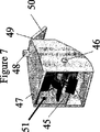
図7は、図6のある実施形態を、ハウジング(47)内でロッド(46)に接続された回転装置(45)を再び用いて説明している。他の実施形態において、ハウジングの側部はコンピュータ制御で調節可能であり、また必ずしも共に固定される必要はない。任意の流入口(48)は、ハウジング内の上方に気体界面を供給する。この実施形態は水中構造において最も有用である。空気/水界面が形成されることにより、パドルの摩擦が減少し、表面波からエネルギを大量に獲得することが可能になる。流体はこの図の左側から入った後、右側から出て行く。流体はある実施形態において、ヒンジ連結部(49)を介し接続された折れ蓋、又は一方向弁(50)を押し開ける。これにより、流体の流出を可能にし、また逆流を防ぐ。ハウジングへの入り口にある任意の固定蓋(51)は、ハウジング内に気体を閉じ込める。ロッド(46)はハウジング内の定位置にある必要はないが、他の実施形態においては上下移動も可能である。理想的な実施形態において、内側の回転装置は、ハウジングへの入り口の前方まで延出しない。 FIG. 7 illustrates one embodiment of FIG. 6 again using a rotating device (45) connected to a rod (46) within a housing (47). In other embodiments, the sides of the housing are computer controlled and need not be secured together. An optional inlet (48) provides a gas interface above the housing. This embodiment is most useful in underwater structures. The formation of an air / water interface reduces paddle friction and allows a large amount of energy to be obtained from surface waves. The fluid enters from the left side of the figure and then exits from the right side. In some embodiments, the fluid pushes open a fold lid or one-way valve (50) connected via a hinge connection (49). This allows fluid outflow and prevents backflow. An optional fixed lid (51) at the entrance to the housing traps gas within the housing. The rod (46) need not be in place in the housing, but in other embodiments it can also be moved up and down. In an ideal embodiment, the inner rotating device does not extend to the front of the entrance to the housing.
図8は、ハウジングに接続される蓋のジョイント(52)及びその接続部(53)が、以前に図示した固定部品(54)よりも低い位置で接続されることを示す。この固定部品(54)は、気体をハウジング内に閉じ込める役目をする。ハウジングの下面(55)は、左側の開口部から上方に傾斜している。ハウジングの下面は、水流(56)がエネルギ獲得部(57)へと浸入する方向に向かって垂直に上昇する。特にハウジングの下面の外側が厚くなり、さらに多くの表面及び垂直エネルギを獲得することが可能になると、砕波効果及びベルヌーイ効果が生み出される。(55)はまた、圧力や速度に違いをもたらすため、様々な位置で厚くしてもよい。 FIG. 8 shows that the lid joint (52) and its connection (53) connected to the housing are connected at a lower position than the previously shown fixing part (54). This fixing part (54) serves to confine the gas in the housing. The lower surface (55) of the housing is inclined upward from the opening on the left side. The lower surface of the housing rises vertically in the direction in which the water flow (56) enters the energy acquisition section (57). In particular, when the outside of the lower surface of the housing becomes thicker and more surface and vertical energy can be acquired, the wave breaking effect and the Bernoulli effect are created. (55) may also be thickened at various locations to make a difference in pressure and speed.
「砕波効果」という言葉は可視的な波の振幅が増加し、したがってより良いエネルギ獲得が可能になることを示すのに使用されることを注意されたい。しかし、実際の砕波は通常は避けられるべきものである。なぜならエネルギがその地点で消失するからである。 Note that the term “breaking effect” is used to indicate that the amplitude of the visible wave is increased, thus allowing better energy gain. However, actual breaking waves should normally be avoided. Because energy is lost at that point.
他の実施形態はハウジング内に配置される回転装置の配列のためのものである。 Another embodiment is for an arrangement of rotating devices disposed within the housing.
ここに述べられる全ての実施形態は、部分的或いは完全に水中のものである。 All embodiments described herein are partially or completely submerged.
<概念の工学応用の議論>
これまでに説明した機構及び後に続く詳細を用い、3Dのコンピュータ化された装置のモデルを作った。既に論じた原理を用いる理想的な実施形態をこれより説明する。
<Discussion of conceptual engineering application>
Using the mechanism described so far and the details that follow, a 3D computerized device model was created. An ideal embodiment using the principles already discussed will now be described.
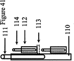
海中の装置を正しい位置及び距離に配置するため、幾つかの選択肢が利用可能である。まず一つは埠頭或いは桟橋である。埠頭或いは桟橋は海中にまで及ぶため、エネルギを陸地へ送り返すことができる。その概念は、杭を海底に沈めること、又は既存の構造体を土台として用いることを恐らく要求し得る。別の選択肢として、ケーブル及びブイが挙げられる。さらに他の選択肢として、既存の石油掘削装置及び沖合にある風力台が挙げられる。他の実施形態には海底(図41)に沈められた1本の長い杭がある。その杭には1以上の装置が取り付けられる。この大きな杭は「複数杭」と呼ばれる。なぜならこの杭は、様々な垂直位置で多くの装置に取り付けられることが可能であるためである。他の実施形態では、杭及びエネルギ獲得装置は組み合わされて「単一杭」(図28)と呼ばれる一つのシステムとなる。上記の選択肢全ては本発明の実施形態である。構造基盤の概念は、海中に一連の設備(ウェーブファーム)が配置される時に最も具現化され、各設備のコストは低減し、流れ偏向平面の効果を大きくする。 Several options are available to place the undersea device at the correct location and distance. The first is the wharf or pier. The wharf or pier extends into the sea so energy can be sent back to the land. The concept could probably require the piles to sink to the seabed or to use an existing structure as a foundation. Another option includes cables and buoys. Still other options include existing oil rigs and offshore wind farms. Another embodiment has a single long pile sunk in the seabed (FIG. 41). One or more devices are attached to the pile. This large pile is called "multiple piles". This is because this pile can be attached to many devices in various vertical positions. In another embodiment, the pile and energy capture device are combined into a single system called a “single pile” (FIG. 28). All the above options are embodiments of the present invention. The concept of structural infrastructure is most embodied when a series of facilities (wave farms) are placed in the sea, reducing the cost of each facility and increasing the effect of the flow deflection plane.
この概念は、運動の2つの垂直方向からエネルギを取り出し、波から最大の電気機械エネルギを獲得することを含む。ほとんどの場合、一方は水平で他方は垂直である。双方向の流れからエネルギを取り出すことは、周知の波の物理学及び特性に基づくものである。 This concept involves extracting energy from two vertical directions of motion and obtaining maximum electromechanical energy from the wave. In most cases, one is horizontal and the other is vertical. Extracting energy from a bidirectional flow is based on well-known wave physics and properties.
ここに表される全ての概念は、様々な流体を用いた実施形態、或いは波の特性を有する気体環境、及び様々な方向に適用することができる。 All the concepts represented here can be applied to embodiments with different fluids, or to a gaseous environment with wave characteristics, and to different directions.
波は長さ(L)、高さ(H)及び水深(h)により特徴付けられる。図9に示すように、長さ、高さ及び水深は、波を伝搬するものである。 Waves are characterized by length (L), height (H) and water depth (h). As shown in FIG. 9, the length, the height, and the water depth propagate waves.
波はまた、図10に示される目に見えない動きもする。表面及び下部にある粒子は、弧を描きながら移動し、その粒子の範囲は表面から離れてさらに減少する。波エネルギが水を通過する時、水粒子は弧を描く動きをする。図10において、エネルギは左側から右側へ通過するが、水粒子そのものは大体同じ位置に留まる。本発明の一つの方法は、理想的な実施形態におけるエネルギ獲得装置をこの範囲の外側に配置することである。そうすることにより、大きい回転エネルギを最大限にすることができ、また小さな回転エネルギからの摩擦を避けることができる。 The waves also have the invisible movement shown in FIG. The particles at the surface and below move while drawing an arc, and the extent of the particles further decreases away from the surface. When wave energy passes through water, water particles move in an arc. In FIG. 10, the energy passes from the left side to the right side, but the water particles themselves remain roughly in the same position. One method of the present invention is to place the energy capture device in an ideal embodiment outside this range. By doing so, large rotational energy can be maximized and friction from small rotational energy can be avoided.
<エネルギ装置モデル>
装置モデルは、粒子の円運動を水平エネルギとして用いることにより、いくつかの実施形態において、パドルホイール、水中タービン装置、プロペラ又は他のエネルギ獲得装置を回転させる。また、波の振幅(H)は垂直エネルギをもたらす。(本発明では、パドル、パドルホイール、回転装置、エネルギ獲得装置及びタービンという言葉は交互に用いられ、本発明に全て応用可能なエネルギ転送装置を示す。理論上においてはパドルが最も機能すると思われる。)回転装置の下には砕波及び/又は流れ偏向装置があり、パドルより低い位置で、上流の速度を増す。この砕波及び/又は流れ偏向装置の理想的な構成条件は、砕波する振幅に及ぶことなく波の振幅を増加させることである。パドルは自由に回転し、表面に浮かび、粒子の円運動から利益を得る。その一方でパドルホイールを含む構造体は、垂直エネルギを発生させるために上下運動する。回転エネルギ装置そのものはシステムの一部であり、そのシステムは運動を垂直エネルギ獲得システムに伝達する。
<Energy device model>
The device model rotates the paddle wheel, submersible turbine device, propeller or other energy capture device in some embodiments by using the circular motion of the particles as horizontal energy. The wave amplitude (H) also provides vertical energy. (In the present invention, the terms paddle, paddle wheel, rotating device, energy acquisition device, and turbine are used interchangeably to indicate an energy transfer device that is all applicable to the present invention. In theory, the paddle seems to work best. .) Below the rotating device is a wave breaking and / or flow deflector that increases the upstream velocity at a position below the paddle. The ideal component of this wave and / or flow deflector is to increase the wave amplitude without reaching the wave breaking amplitude. The paddle rotates freely, floats on the surface, and benefits from the circular motion of the particles. On the other hand, the structure including the paddle wheel moves up and down to generate vertical energy. The rotational energy device itself is part of the system, which transmits motion to the vertical energy acquisition system.
砕波装置の影響は、最初の計算段階では考慮されないことに注意されたい。その影響は「単一杭」より得られたエネルギを後に計算する時に考慮する。全ての場合において、単一杭はエネルギを大幅に増加させる。単一杭は砕波装置とも呼ばれ(波を砕くことを意味しないわけでなく、むしろその振幅をも示す)、又は翼部形状装置、又は斜面、又は流れ偏向装置とも呼ばれる。全ての場合において、図11に示されるように、上方の反り部は下方の反り部より大きくする必要がある。 Note that the effect of the breaking device is not taken into account in the first calculation stage. The effect will be taken into account later when calculating the energy obtained from “single pile”. In all cases, a single pile greatly increases energy. A single stake is also referred to as a wave breaking device (not meant to break the wave, but rather shows its amplitude), or a wing shape device, or a slope, or a flow deflection device. In all cases, as shown in FIG. 11, the upper warped portion needs to be larger than the lower warped portion.
図12のブロック図は、理想的な実施形態において本装置を用い、エネルギを作る基礎的な方法及び全体的な概念を要約している。本装置はまた、想定される資源と相関性があるので、各段階で投資が必要となることは明らかである。生産される理論電力を計算することを基本前提とするが、実地での試験及び試行を実際に行うことが後の段階で必要となる。 The block diagram of FIG. 12 summarizes the basic method and overall concept of creating energy using the device in an ideal embodiment. It is clear that the device also has a correlation with the envisaged resources and therefore requires investment at each stage. Although the basic assumption is to calculate the theoretical power produced, actual testing and trials in the field will be required at a later stage.
<計算方法>
まずエネルギ生産装置に作用する力、及びこれらの装置により生産されたエネルギを計算する。次の段階は、力学或いは風抗力のため発生した損失見積額を差し引く。最後に、時間あたりの仕事量を計算し、電力をワットで得る。計算は、特に明記されていなければメートル法を使用する。
<Calculation method>
First, the forces acting on the energy production devices and the energy produced by these devices are calculated. The next step is to subtract the estimated loss caused by mechanics or wind drag. Finally, calculate the work per hour and get the power in watts. Calculations use metric unless otherwise specified.
さらに容易な証明及び説明のため、ここではタービンでなくパドルホイールを用いた。
<物理的証明>
小振幅理論
二次元の進行表面重力波
波の振幅は波の長さよりも非常に小さい
波の振幅は水深よりも非常に小さい
自然の波周波数は経時的に変化するが、時間に関しては平均値を用いる。
図13に図示されるようなG1、G2及びG3により発生した電力
ジョイントJ1、J2は機械のユニバーサルジョイントを表す
それぞれの機構(機械的及び電気機械的)は欠損を有する
For easier proof and explanation, a paddle wheel was used here instead of a turbine.
<Physical proof>
Small amplitude theory The amplitude of a two-dimensional traveling surface gravity wave wave is much smaller than the wave length. The wave amplitude is much smaller than the water depth. Use.
The power joints J1, J2 generated by G1, G2, and G3 as illustrated in FIG. 13 are mechanical mechanisms and mechanical mechanisms (mechanical and electromechanical) each representing a mechanical joint.
図13は装置のパラメータ及び事例的実施形態において、そのパラメータが機械的に動く方法を図式的に示す。装置上にはG1,G2及びG3の3つの発生装置がある。G1は左側に配置され、接続したロッドの揺れ運動及び垂直運動から電力を生み出す。G2はパドルの回転運動から電力を生み出す。G3は装置の右側のスウィングロッドによって電力を生み出す。G2はG1及びG3に接続し、二つのユニバーサルジョイントJ1及びJ2の間のロッドを固定する。 FIG. 13 diagrammatically shows the parameters of the device and in the exemplary embodiment how the parameter moves mechanically. There are three generators G1, G2 and G3 on the device. G1 is located on the left side and generates power from the swinging and vertical movements of the connected rods. G2 generates power from the paddle rotation. G3 generates power by a swing rod on the right side of the device. G2 connects to G1 and G3 and fixes the rod between the two universal joints J1 and J2.
<エネルギ生産>
図13の装置において、エネルギを生産するものは2種類あり、一つのパドルホイール、2つのオシレータである。
パドルホイールは波面の粒子運動によりスピードを変化させて回転する。パドルの表面は圧力を用い、動的な流れを回転運動エネルギに変換する。それが全体的なモーションシステムである。
オシレータの作用は波の上下運動により得られる。オシレータに繋げられた浮遊しているパドルホイールに影響を与える力は、力及び浮力である。これらは付加的なモーションシステムである。
<Energy production>
In the apparatus of FIG. 13, there are two types that produce energy, one paddle wheel and two oscillators.
The paddle wheel rotates by changing the speed by the particle motion of the wave front. The paddle surface uses pressure to convert dynamic flow into rotational kinetic energy. That is the overall motion system.
The action of the oscillator is obtained by the vertical movement of the wave. The forces that affect the floating paddle wheel connected to the oscillator are forces and buoyancy. These are additional motion systems.
その他のエネルギ変換構成部材は、図13の左側に図示されるピストン運動をする。装置がさらに高い波の場所へ導入されると、ピストン運動は高エネルギを生産することができる。計算には周知の電磁気装置変数を用いる。(この実施形態の種類は、上に挙げられるエネルギ変換構成部のいずれを含んでもよい。即ちパドルホイール、1以上の変換器、及び1以上のピストンを含む。本特許又は本特許のあらゆる点において、発電機を正しい位置で接続することは、その都度特に説明せずともシステムの一部とする。 The other energy conversion components perform the piston motion illustrated on the left side of FIG. As the device is introduced into higher wave locations, the piston motion can produce high energy. The calculation uses well-known electromagnetic device variables. (This type of embodiment may include any of the energy conversion components listed above, including a paddle wheel, one or more transducers, and one or more pistons. Connecting the generators in the correct position is a part of the system without specific explanation each time.
<パドルホイール分析>
図14は、波の複数の変数及び回転力を生み出すパドルに作用する力を図示したものである。粒子の流速(v1)はパドルに作用し圧力を発生させる。この圧力はポイントP1において、単一の力を生み出すとされる。これらの力は、時間、パドルの位置、及び静的流体力及び動的流体力と共に変化する。パドルは水平の位置で水面に近づく。そしてパドルは傾斜し、水中の垂直位置で最大水平力に近づく。そしてパドルは回転し、水平位置に戻るまで傾斜し、水面から離れる。
<Paddle wheel analysis>
FIG. 14 illustrates the forces acting on the paddles that produce the wave variables and the rotational force. The particle flow velocity (v1) acts on the paddle to generate pressure. This pressure is said to produce a single force at point P1. These forces vary with time, paddle position, and static and dynamic fluid forces. The paddle approaches the water surface in a horizontal position. The paddle then tilts and approaches the maximum horizontal force at a vertical position in the water. The paddle then rotates, tilts back to the horizontal position and moves away from the water surface.
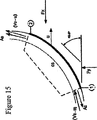
<パドルの形状>
パドルの形状は重要であり、好適な実施形態においてその形状が定義される。平面のパドルを用いることは効果的ではない。最高エネルギ及び最高速度を持つ粒子が水面下にあることは以前に説明している。粒子を最大限に利用する必要があるので、ホイールのパドルの形状が重要となる。形が重要である理由としては、水の外でパドルに作用する風力が他にあげられる。したがって、図15では、上記の目的に沿った最適形状を明示する(後にパドル上の延出部の追加可能な実施形態は、これらの計算において論じられず、後に議論される。パドルは波の振幅が増加しても、パドル上の延出部により適合可能である。)。本発明の方法は、所定の位置において波の状態を平均化させる形状のパドルを特別に生産する。標準的な構造は計算されるものであり、一般的に波の外半径領域のみ選択的に獲得することができる。
形状に作用する力によりホイールが回転し、このホイールの回転により工程が処理される。この工程は多くの羽根を用いることにより、数値が求められ、そして増加する。
制御ボリュームの線形運動量の方程式が電力を数値化するために用いられる。電力はこの羽根から獲得される。
<Paddle shape>
The shape of the paddle is important and is defined in the preferred embodiment. Using a planar paddle is not effective. It has been previously described that particles with the highest energy and highest velocity are below the surface of the water. The shape of the wheel paddle is important because it is necessary to make maximum use of the particles. Another reason why the shape is important is the wind that acts on the paddle outside the water. Thus, in FIG. 15, the optimal shape for the above purpose is demonstrated (additional embodiments of extensions on the paddle are not discussed later in these calculations and will be discussed later. Even if the amplitude increases, it can be accommodated by the extension on the paddle.) The method of the present invention specifically produces paddles that are shaped to average the state of the wave at a given location. The standard structure is calculated and generally only the outer radius region of the wave can be acquired selectively.
The wheel is rotated by the force acting on the shape, and the process is processed by the rotation of the wheel. This process uses many blades, and the numerical value is determined and increased.
A linear momentum equation of the control volume is used to quantify the power. Power is obtained from this blade.
上記の方程式を用い、パラメータを最大電力出力に最適化することができる。グラフ中では、様々な変数の変化と共に得られるエネルギが示される。
グラフ1:羽根の角度は、流入口における流量方向及び羽根の曲線間の角度である。電力はパドル/羽根の角度の増大と共に増える。
グラフ2:流量区域は流れが通過する場所で、流れが羽根に当り回転させる区域である。電力は流量が増すほど増加する。
グラフ3:流入口のスピードが増大すると電力は増えるが、羽根の角度は45度で変わらないままである。
グラフ4:流入口のスピードが増大すると電力は増えるが、羽根の角度は60度で変わらないままである。
グラフ3及び4は、流量と羽根の間が40度或いは60度の場合に抽出された電力に対する流速の影響を説明するものである。角度がさらに大きくなれば、ホイールの回転運動からますます多くの潜在電力を生み出されることは明らかである。
風速に基づく波の速さ及び流速は、以下の表及び図16に表される。
Using the above equation, the parameters can be optimized for maximum power output. In the graph, the energy obtained with changes in various variables is shown.
Graph 1: The blade angle is the angle between the flow direction at the inlet and the blade curve. The power increases with increasing paddle / blade angle.
Graph 2: The flow area is where the flow passes and the area where the flow strikes the blades and rotates. The power increases as the flow rate increases.
Graph 3: Power increases as the inlet speed increases, but the blade angle remains unchanged at 45 degrees.
Graph 4: Power increases as the inlet speed increases, but the blade angle remains unchanged at 60 degrees.
The wave speed and flow velocity based on the wind speed are shown in the following table and FIG.
<オシレータ解析>
振動を発生させる力は両側のロッドの終端部で運動を引き起こす。これらの力は波の振動数と同じ振動数で振動する。
図17は2つの変更形態における発振器装置(オシレータ)を図示する。右側にある方は定位置にあり、左側にある方はピストン状の垂直運動を行う。これらの装置は、海水位や波の特性、及び流れの管理に左右されるので、どちらか一方の装置を用いても、または両方の装置を組み合わせて用いるのも可能である。力及び速度は計算に最も当てはまる変数である。
<Oscillator analysis>
The force that generates vibration causes movement at the end of the rod on both sides. These forces oscillate at the same frequency as the wave.
FIG. 17 illustrates an oscillator device (oscillator) in two variations. The one on the right side is in place and the one on the left side performs a piston-like vertical movement. Since these devices depend on the sea level, wave characteristics, and flow management, it is possible to use either one or a combination of both. Force and speed are the variables most relevant to the calculation.
Fg及びFBが示す矢印は、ホイールに作用する力の反射である。ユニバーサルジョイントは、機械力ではなく機械的モーメントを、あるロッドからもう一方のロッドへ変換する。しかし理解しやすいように、図においては力について言及する。V1,ω1、及びω2は重要な変数である。なぜならこの場合、V1,ω1、及びω2は運動エネルギを提供し、また電力を生産するからである。Fg及びFBの力は詳細設計の後半にて決定される変数である。 The arrows indicated by Fg and FB are reflections of the force acting on the wheel. Universal joints convert mechanical moments rather than mechanical forces from one rod to the other. However, for ease of understanding, the figures refer to forces. V1, ω1, and ω2 are important variables. This is because in this case, V1, ω1, and ω2 provide kinetic energy and produce power. Fg and FB forces are variables determined in the second half of the detailed design.
次に、波エネルギを運動エネルギに変換する一方で、波エネルギにより得られる電力を注視する。仕事の原理及び剛体エネルギから、次の方程式を得ることができる。この方程式は、全ての運動エネルギ、及び保存されたシステム上に作用する全ての力の仕事を表す。 Next, while converting the wave energy into kinetic energy, the power obtained by the wave energy is watched. From the work principle and rigid body energy, the following equation can be obtained: This equation represents the work of all kinetic energy and all forces acting on the stored system.
これは並進部及び回転部を表す。これら並進部及び回転部は、システム及び重心周囲のシステムの動きに関連する。
エネルギ保存の法則に従う一方で、波の垂直運動(頂点から底)から放出される全てのエネルギは、運動エネルギに変換されるものとする。
This represents a translation part and a rotation part. These translation and rotation parts are related to the movement of the system and the system around the center of gravity.
While following the law of conservation of energy, all energy released from the vertical motion of the wave (from top to bottom) shall be converted to kinetic energy.
<エネルギ計算>
自由体図(図18)を用いて、動きの運動学を解決し、運動エネルギ及びエネルギ保存を推進して、本装置により仕事と電力の量を得ることができる。概略図中には2つの位置がある。一方はポイントBが波上部位置にある場合を、もう一方は波下部位置にある場合を示す。
<Energy calculation>
The free body diagram (FIG. 18) can be used to solve the kinematics of motion, promote kinetic energy and energy conservation, and obtain the amount of work and power with this device. There are two positions in the schematic. One shows the case where the point B is at the wave top position and the other shows the case where the point B is at the wave bottom position.
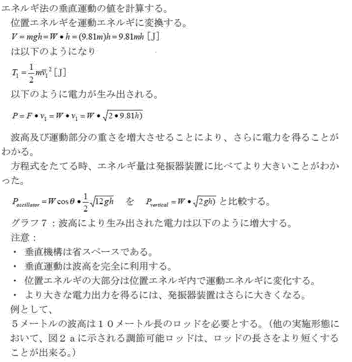
下方のロッドに作用する唯一の力である限り、ロッドの機械動力はWである。実際、位置1から位置2へ振動ロッドを下へ引く力は重力のみに起因する。上記の等式を用いて、変数を一番の電力出力に最適化することができる。以下のグラフで、様々な変数の変化に伴う電力利得がわかる。
As long as it is the only force acting on the lower rod, the mechanical power of the rod is W. In fact, the force pulling the vibrating rod down from
グラフは2つの変数、すなわち波運動及び電力出力におけるロッド重量及び波高を示す。 The graph shows two variables: rod weight and wave height at wave motion and power output.
グラフ5:電力は振動ロッドの増加した重量と共に増大する。グラフから明らかである通り、ロッド重量は位置エネルギ及びこの方法で力を獲得する能力に影響する。欠点は、システムの総重量及び単価が増大する点である。 Graph 5: Power increases with increasing weight of vibrating rod. As is apparent from the graph, the rod weight affects the potential energy and the ability to acquire force in this way. The disadvantage is that the total weight and unit price of the system increases.
グラフ6:電力は波高が増加するに連れて増大する。グラフ中で、波が更に高くなればなるほど、ますます大きな電力が獲得される。しかしこれは回転機構により制限される。この回転機構は、波高を完全にはエネルギに利用することはできない。 Graph 6: The power increases as the wave height increases. In the graph, the higher the wave, the more power is gained. However, this is limited by the rotation mechanism. This rotating mechanism cannot fully use the wave height for energy.
<垂直運動エネルギ>
その他の選択肢としては波の運動を利用する。ユニバーサルジョイント(J1)を取り除き、又はユニバーサルジョイントを制限し、波が上下に動く様に垂直な(ピストン状の)運動(V1)を作り出す。(図19)ピストン及びパドルの組み合わせも本発明の実施形態である。
<Vertical kinetic energy>
Another option is to use wave motion. Remove the universal joint (J1) or restrict the universal joint to create a vertical (piston-like) motion (V1) so that the waves move up and down. (FIG. 19) A combination of a piston and a paddle is also an embodiment of the present invention.
<単一杭装置>
パドルホイールに結合された純然たる垂直エネルギを用いる実施形態は以下の通りである。図20を参照されたい。(59)は海底に取り付けられた杭である。(60)はピストン状の構造体である。パドルホイール(61)が、波上で回転し、浮遊し、及び上下に動くにつれて、このピストン状の構造体も上下に動く。(62)はポイントであり、発電機(詳細に図示されていない)がパドルホイールの回転を電気エネルギに変換し、ピストン状の構造体を上下に引っ張るものである。
<Single pile device>
An embodiment using pure vertical energy coupled to a paddle wheel is as follows. See FIG. (59) is a pile attached to the seabed. (60) is a piston-like structure. As the paddle wheel (61) rotates on the wave, floats and moves up and down, the piston-like structure also moves up and down. (62) is a point, and a generator (not shown in detail) converts the rotation of the paddle wheel into electric energy and pulls the piston-like structure up and down.
<翼部/流れ偏向の影響>
本発明のパドルホイールの下に配された斜面は、波高を増大させ、さらなる運動エネルギ及び電力出力を得る。図21及び図22は流れ偏向装置及び斜面の影響を図示している。図21及び図22において、1以上のピストン状プロセスを利用することは任意である。図22は断面図である。
図21の流れ偏向装置(63)はホイール(64)の下の最適位置を調節するために測定される。ホイール(64)は、3本の垂直ロッド(66)が杭の内部を上下に動くため、変動する。(杭の内部では一本のロッドのみが必要である。図はある実施形態を示す。)翼部形状がホイールの下の制御された場所で維持されるならば、この翼部形状はホイールにより早い速度をもたらすことができる。その他の場合では、翼部に作用する上昇力が得られ、この翼部によりシステムを波と共に上昇させる。ピストンセット(66)は、理想的な実施形態において、各セットにつき1つのピストンを有する。しかし、他の実施形態では、1つ以上であってもよい。(63)は図示される翼部形状装置、又は傾斜のより大きい斜面状の装置、又はその二つを組み合わせたものであってもよい。(63)は別の杭、又は構造体(65)、又はより直接的にエネルギ獲得装置に取り付けられてもよい。図21及び22は、一つのパドルのみを図示するが、他の実施形態においてはさらにパドルの追加可能である。或いはパドルの幅は中心ロッドに沿って延出されてもよい。
図の装置が発電装置の位置に関していくつかの可能性を提供することを注意されたい。すなわち、パドル及びパドルの回転エネルギ、回転ロッドが垂直構造体に接する場所にある回転固定子、及びピストン状の構造体の低位運動である。
この図及び別の図で、発電機を配置する場所はどんな組み合わせでも可能である。そのうちのいずれか1つが、必要に応じて除去されることが可能である。特定の地理的な場所への理想的な配置は、局所的条件に依存する。例えば、回転固定子の実施形態は、波の振幅が大きな場所では有用性は低く、波の振幅が小さな場所においてはさらに有用となる。ピストン状の実施形態は、波の振幅が小さい場所では有用性は低く、波の振幅の大きい場所においてさらに有用となる。本特許の方法の一部は、波高を計算し、理想的な組み合わせを決定することである。波高が非常に低い位置から非常に高い位置へと変化する場所において、ピストン及び回転固定子装置の両方は同じシステムに配置されることが可能である。
<Influence of wing / flow deflection>
The slope located under the paddle wheel of the present invention increases the wave height and provides additional kinetic energy and power output. 21 and 22 illustrate the influence of the flow deflector and the slope. 21 and 22, it is optional to use one or more piston-like processes. FIG. 22 is a cross-sectional view.
The flow deflector (63) of FIG. 21 is measured to adjust the optimum position under the wheel (64). The wheel (64) fluctuates as the three vertical rods (66) move up and down inside the pile. (Only one rod is needed inside the pile. The figure shows an embodiment.) If the wing shape is maintained in a controlled location under the wheel, this wing shape is Can bring fast speed. In other cases, a lifting force acting on the wings is obtained, which raises the system with the waves. The piston sets (66) have one piston for each set in an ideal embodiment. However, in other embodiments, there may be one or more. (63) may be a wing-shaped device shown in the figure, a slope-like device having a larger slope, or a combination of the two. (63) may be attached to another pile, or structure (65), or more directly to the energy capture device. 21 and 22 illustrate only one paddle, other paddles can be added in other embodiments. Alternatively, the width of the paddle may extend along the central rod.
Note that the apparatus shown provides several possibilities for the location of the generator set. That is, the rotational energy of the paddles and paddles, the rotating stator in the place where the rotating rod contacts the vertical structure, and the low-order motion of the piston-like structure.
In this figure and another figure, any combination of locations for the generators is possible. Any one of them can be removed as needed. The ideal placement at a particular geographical location depends on local conditions. For example, the rotating stator embodiment is less useful where the wave amplitude is large and more useful where the wave amplitude is small. Piston-like embodiments are less useful in locations where the wave amplitude is small and are more useful in locations where the wave amplitude is large. Part of the method of this patent is to calculate the wave height and determine the ideal combination. Where the wave height changes from a very low position to a very high position, both the piston and the rotating stator device can be arranged in the same system.
図23は流動様式を表す。翼部の位置は最高流速の点に最適化されるため、ホイールの回転が助長され、上昇力が加えられる。その一方で、羽根正面上の速度は増す。翼部周囲の流れにより、頂上部の速度が増し、底部の圧力が高まる。翼部形状構造体の先端は様々な実施形態において、鋭い形又は丸い形をしている。他の実施形態において、翼部形状構造体は表面エネルギ獲得装置、又は海底のどちらか一方に関連して、固定された位置にある必要はない。しかし、翼部形状構造体は、ピストン及び発電機に接続されてもよい。その場合、重みつけ、翼部形状構造体、及び表面エネルギ獲得装置は衝突を避けるよう調整されなければならない。
エネルギ保存の法則に基づいたベルヌーイの定理を用いて保存された層流及び流線を仮定すると、パドルの回転を促進する加速の存在が予測される。図23及び24はベルヌーイ効果を図示したものである。
FIG. 23 represents the flow pattern. Since the position of the wing is optimized for the point of maximum flow velocity, rotation of the wheel is promoted and a lifting force is applied. On the other hand, the speed on the blade front increases. The flow around the wing increases the speed at the top and increases the pressure at the bottom. The tip of the wing-shaped structure has a sharp or round shape in various embodiments. In other embodiments, the wing-shaped structure need not be in a fixed position relative to either the surface energy capture device or the seabed. However, the wing-shaped structure may be connected to the piston and the generator. In that case, the weight, wing shape structure, and surface energy capture device must be adjusted to avoid collisions.
Assuming laminar flow and streamlines preserved using Bernoulli's theorem based on the law of conservation of energy, the existence of accelerations that promote paddle rotation is predicted. 23 and 24 illustrate the Bernoulli effect.
<電力の概要>
ここに紹介したエネルギの様々な方法は、一年中一週7日一日24時間常に発電可能である。本特許で記載された装置を配することができる様々な場所があり、例えば深海及び浅水域などが該当する。
ここに説明される装置は、重ねたり、連続して配置したり、長い波面で用いられたりしても構わない。海の流れは変化し得るので、そのため本記載中では平均速度及び速度を議論する。
一時間当りのエネルギが生産する電力をここに示す。
プロトタイプモデルの以下の変数を考慮する。
羽根の角度=60°(θ)
パドル表面積=0.003m2
パドル半径=119mm(r)
パドルの刃=6
流量断面=0.0015m2
流速=翼部を用いて13m/秒(u)(翼部なしの場合、穏やかな海において10m/秒と仮定する)
仮定:パドルは既に相対速度を持つのでゼロから始めないものとする。
平均波高=1.2m
ロッド質量=双方それぞれ3.5kg(W)
ロッドの長さ=2.4m
ロッド外径=5cm
ロッド内径=4.2cm
波長〜40m(理論上)
波の周期=10秒
最大振動角=30°
<Outline of power>
The various methods of energy introduced here can always generate electricity 24 hours a day, 7 days a week throughout the year. There are various places where the device described in this patent can be placed, for example deep seas and shallow waters.
The devices described herein may be stacked, placed sequentially, or used with a long wavefront. Sea currents can vary, so average speed and speed are discussed in this description.
Here is the power produced by the energy per hour.
Consider the following variables in the prototype model:
Blade angle = 60 ° (θ)
Paddle surface area = 0.003m2
Paddle radius = 119mm (r)
Paddle blade = 6
Flow rate cross section = 0.0015m2
Flow velocity = 13 m / sec (u) with wings (assuming 10 m / s in calm seas without wings)
Assumption: The paddle already has a relative speed and will not start from zero.
Average wave height = 1.2m
Rod mass = 3.5 kg (W) for both
Rod length = 2.4m
Rod outer diameter = 5cm
Rod inner diameter = 4.2cm
Wavelength ~ 40m (theoretical)
Wave period = 10 seconds Maximum vibration angle = 30 °
<全体的なエネルギ出力>
装置毎の全体的な出力は、上記の2つの構成要素の合計である。したがって、1時間で約210kWを得る。1日で、210kW/hr×24時間=5040kWを得る。
電流及び電圧が生成される頃までに、用いる技術に応じて効率問題が生じる(図25を参照それば損失の原因が視覚化される)。
電力出力には悲観的な仮定が用いられた。その仮定は悪化した場合の損失を予測したためであり、この場合においては流体エネルギのわずか10%しか電気エネルギに変換されない。他方では、構成要素及び技術を最適化することにより楽観視することも可能であり、さらに最大で15%のエネルギを得られる。したがって25%の利用可能なエネルギを獲得する。
結論:一日当り、最小で504kW、或いは最大で1260kWのエネルギを獲得する。また最小21kW/hr、或いは最大52.5kW/hrと表すこともできる。
<Overall energy output>
The overall output per device is the sum of the above two components. Therefore, about 210 kW is obtained in one hour. In one day, 210 kW / hr × 24 hours = 5040 kW is obtained.
By the time the current and voltage are generated, efficiency problems arise depending on the technique used (see FIG. 25, which causes the cause of the loss to be visualized).
Pessimistic assumptions were used for power output. The assumption is to predict the loss when it gets worse, in which only 10% of the fluid energy is converted to electrical energy. On the other hand, optimism is also possible by optimizing the components and technology, and up to 15% energy can be obtained. Therefore, 25% of available energy is obtained.
Conclusion: Obtain a minimum of 504 kW or a maximum of 1260 kW of energy per day. It can also be expressed as a minimum of 21 kW / hr or a maximum of 52.5 kW / hr.
<更なるエネルギの獲得>
更にエネルギを獲得するために、いくつかの方法が存在する。
羽根の表面をより大きくして、ホイールの上の流れを増やす。
装置群を配することにより、同じ装置で得られるよりも多くのエネルギを得られる。
人工の斜面及び制御装置を付加し、波高をより大きくする。
図26、27、28において、装置群内でどのようにしてより多くのエネルギを獲得するかがわかる。
更なる流量を備えたより大きな羽根は、結果として、より多くのエネルギ及び装置構造の巨大化をもたらす。このように、より小さな海底部を有する構造が得られるが、波長ごとの流れはさらに大きくなる。
<Acquisition of further energy>
There are several ways to gain more energy.
Increase the flow on the wheel by making the blade surface larger.
By arranging the device group, more energy can be obtained than that obtained by the same device.
Add artificial slopes and control devices to increase the wave height.
In FIGS. 26, 27 and 28, it can be seen how more energy is acquired within the device group.
Larger vanes with additional flow rates result in more energy and device structure enlargement. In this way, a structure having a smaller seabed is obtained, but the flow per wavelength is even greater.
<単一杭>
単一杭は単純な垂直ロッドである。波表面エネルギ、及び、ピストン運動を同時に利用することができる。これにより、上下運動の位置エネルギを(ある実施形態において80kgの重さの動く部分を用いて)獲得することができる(図20)。図20では、パドル及び他のエネルギ獲得装置は、理想的にはロッド上部付近に配置されるのが好ましい。理想的な実施形態において、一本のロッドはパドルを支え、ピストンの機能を果たすことにより発電システムの中へ挿入される。他の実施形態において、少なくとも一本のロッドがピストン発電システムの一部である。垂直ロッドには1以上のパドルホイールが取り付けられている。取り付け手段は垂直ロッド及び発電機にパドルホイールを接続する。理想的な実施形態において、各側部のパドルホイールの数及び大きさはバランスが保たれている。理想的な実施形態としては、各側部それぞれに3つのパドルがあり、その3つのパドルの各組は互いに近接近している。斜面及びパドルシステムの下にある翼部形状構造体の実施形態は、この図に示されていない。理想的な実施形態において、制御手段は流体の流れに関連して理想的な位置へとパドルを導く。この制御手段は、ピストンの役割をする垂直ロッドの回転を介して、ピストン状ロッドのホルダーか、或いはホルダーが杭の運動手段に取り付けられていてもよい。「単一杭」と名づけられているが、それは浅瀬において理想的な構造である。より水深の深いところでは、理想的には、単一杭は水域の底にまで延出する杭、或いはその他の支持構造体に接続されるのが望ましい。これを複数杭と呼ぶ。
2つのアームが外側に吊るされている単一柱、及び水面上で回転するパドルからエネルギが生産されることが実証される。
この構造体は他の発明の深海エネルギ発電機、又は本方法の深海エネルギ発電機を組み合わせることが可能である。本方法は本発明中に水面下の装置のエネルギを獲得すると記載されている。その組み合わせは、さらに深い水位において、深海エネルギ発電機を複数杭の基礎構造に取り付けることによりなされる。すなわち、同じ基礎構造を用いることによりコスト削減が可能となる。
<Single pile>
A single pile is a simple vertical rod. Wave surface energy and piston motion can be used simultaneously. Thereby, the potential energy of the up and down movement can be obtained (in one embodiment using a moving part weighing 80 kg) (FIG. 20). In FIG. 20, the paddle and other energy capture devices are ideally located near the top of the rod. In an ideal embodiment, a single rod is inserted into the power generation system by supporting the paddle and performing the function of a piston. In other embodiments, at least one rod is part of a piston power generation system. One or more paddle wheels are attached to the vertical rod. The attachment means connects the paddle wheel to the vertical rod and the generator. In an ideal embodiment, the number and size of the paddle wheels on each side is balanced. In an ideal embodiment, there are three paddles on each side, and each set of three paddles is in close proximity to each other. The embodiment of the wing-shaped structure under the bevel and paddle system is not shown in this figure. In an ideal embodiment, the control means directs the paddle to an ideal position relative to the fluid flow. The control means may be a piston rod holder or a holder attached to the pile motion means via rotation of a vertical rod acting as a piston. Although named “single pile”, it is an ideal structure in shallow water. At deeper depths, ideally, a single pile should be connected to a pile extending to the bottom of the body of water, or other support structure. This is called a multiple pile.
It is demonstrated that energy is produced from a single column with two arms suspended outside and a paddle that rotates on the surface of the water.
This structure can be combined with the deep sea energy generator of other inventions or the deep sea energy generator of the present method. The method is described in the present invention as capturing the energy of an underwater device. The combination is made by attaching a deep-sea energy generator to a multi-pile foundation structure at deeper water levels. That is, the cost can be reduced by using the same basic structure.
<エネルギ領域>
装置それぞれに作用する流量は、波力のバランスを取る傾向がある。すなわち、装置それぞれが比較的正確に波面に向かい合う。エネルギファームは垂直に立てられるので、単一杭パドルシステムはお互いに接触しない。理想的な実施形態では、機械が回転可能であるならば、360度回転しても接触しない(図26から28)。
<Energy area>
The flow rate acting on each device tends to balance the wave forces. That is, each device faces the wavefront relatively accurately. Since the energy farms are erected vertically, the single pile paddle systems do not touch each other. In an ideal embodiment, if the machine is rotatable, it will not touch even after rotating 360 degrees (FIGS. 26-28).
<斜面エネルギ領域>
表面速度を上げるために斜面を用いることは、より大きいエネルギ(パドル速度)を生み出す。エネルギの産出はパドルの回転を加速させ、また圧力を下げることによりなされる。注意すべきことは波が砕波点に達しないことである。そうでないと乱流の極限に達し、エネルギを損失してしまうからである。本発明の装置及び方法の一部は、システムを様々な波の状態に応じて制御するマイクロプロセッサを含む。
<Slope energy range>
Using ramps to increase the surface speed creates greater energy (paddle speed). Energy is produced by accelerating paddle rotation and reducing pressure. It should be noted that the waves do not reach the breaking point. Otherwise, the limit of turbulence will be reached and energy will be lost. Some of the devices and methods of the present invention include a microprocessor that controls the system in response to various wave conditions.
斜面の追加による計算の大きな利得は、速度効果の結果である。
図28は斜面の概念の実施形態を示す。図は1つの、接続された大きな斜面を表す。他の実施形態はそれぞれに斜面を有する各単一杭のためのものである。また個々の斜面を有する単一杭は、エネルギ獲得装置(水面上或いは水面下にあっても)の下方でほぼ隣接する斜面を形成するよう共に設置される。図示される斜面は、斜面と翼部形状構造体のハイブリッド(組み合わせ構造体)である。上面の斜面部分、特に斜面上部は、波の振幅を増加させるよう機能する。その結果、獲得可能な垂直エネルギを増加させる。斜面の一部分が実体積又は中空体積を有する翼部のような形をしているという事実により、斜面上方の水の速度を増加させることでベルヌーイの原理を応用することができる。実施形態はまた、斜面、斜面を有さない翼部形状物体、及びパドル下方の翼部形状物体、又はさらに低位の斜面に加え表面エネルギ獲得装置を、基本的に平面に設置することも可能である。斜面の使用方法の一部は変化する波の状況下で理想的な配置を決定する。
特有な個々の斜面を持つ単一杭の場合は、制御システムは斜面の角度及び方向を決定できる。
The large calculation gain due to the addition of the slope is the result of the speed effect.
FIG. 28 shows an embodiment of the slope concept. The figure represents one large connected slope. Another embodiment is for each single pile with a slope on each. Single piles with individual slopes are also installed together to form a substantially adjacent slope below the energy capture device (even above or below the water surface). The slope shown is a hybrid (combination structure) of a slope and a wing-shaped structure. The sloped portion of the top surface, particularly the top of the slope, functions to increase the wave amplitude. As a result, the available vertical energy is increased. Due to the fact that part of the slope is shaped like a wing with a real or hollow volume, the Bernoulli principle can be applied by increasing the speed of water above the slope. Embodiments can also basically install surface energy acquisition devices on a flat surface in addition to slopes, wing-shaped objects without slopes, and wing-shaped objects below the paddle, or even lower slopes. is there. Part of the use of slopes determines the ideal placement under changing wave conditions.
In the case of a single pile with unique individual slopes, the control system can determine the angle and direction of the slope.
<エネルギ獲得の概要>
前に述べた計算及び仮定によると、それぞれ異なる配置においてのみのパドルの回転から得られるエネルギは、下の表の一覧においてキロワット/時間で要約される。
<Overview of energy acquisition>
According to the calculations and assumptions described earlier, the energy gained from paddle rotation only in different configurations is summarized in kilowatts / hour in the list in the table below.
<位置エネルギの利得>
単一杭を有する方法における振動エネルギはさらに単純であって、垂直ピストン運動として機能する。
位置エネルギは全て運動スピードに変換され(もしシステムがうまくバランスを保ち、滑り軸受を用いる場合、摩擦損失は垂直運動により最小となる)、また電力は波の周期によって上下運動する集合体から生成される。このエネルギは純粋に機械的なものであり、垂直方向に動きを生み出す波の運動に依存する。
様々な場所において垂直運動が2メートルから10メートルの間で変化すると仮定すると、得られるエネルギを計算することができる。下の表はそのようなエネルギの出力を要約したものである。(控えめな仮定の観点からみれば、斜面は高速化における方が益々多くのエネルギを垂直運動に付加することを注意されたい。それ故、総エネルギではなく、ここにおける位置エネルギが斜面なしの場合よりも小さい理由である。)
<Gain of potential energy>
The vibration energy in the method with a single pile is simpler and functions as a vertical piston motion.
All potential energy is converted to motion speed (if the system is well balanced and sliding bearings are used, friction loss is minimized by vertical motion), and power is generated from an assembly that moves up and down with the wave period. The This energy is purely mechanical and depends on the motion of the waves creating motion in the vertical direction.
Assuming that the vertical motion varies between 2 and 10 meters at various locations, the resulting energy can be calculated. The table below summarizes the output of such energy. (Note from a conservative point of view that slopes add more energy to vertical motion at higher speeds, so if the potential energy here is not slopes, not total energy. Is a reason smaller than that.)
<波変換に関する結論>
垂直運動は最小幅から最大幅へ20%から25%を付加することが可能である。アレイ配置では、パドルの回転は支配的要因である。
<Conclusion on wave conversion>
Vertical motion can add 20% to 25% from minimum width to maximum width. In an array arrangement, paddle rotation is the dominant factor.
<各装置の使用>
各装置の使用は波の大きさ(長さ及び高さ)に依存する。
図示される単一杭は理想的な実施形態である。ユニバーサルジョイントを用いる配置では、ユニバーサルジョイントによって中心ロッドへ接続されたロッドは垂直運動に、対応するよう動くこと、或いは本システムの他の構成物は垂直運動に対応するように動かねばならないことに注意されたい。
<Use of each device>
The use of each device depends on the wave size (length and height).
The single pile shown is an ideal embodiment. Note that in a universal joint arrangement, the rod connected to the central rod by the universal joint must move to accommodate vertical movement, or other components of the system must move to accommodate vertical movement. I want to be.
<ユニバーサルジョイント装置>
ユニバーサルジョイント装置は、浅水域や低振幅の波に理想的に限定されると望ましい。垂直方向における装置は小さいが、長い陸地が必要であり、したがって取り付けられる装置が少ない。そのような装置を限定するものは長いアームである。長いアームは位置エネルギを必要とし、また波の表面に安定したバランスのとれた位置を保つ能力を必要とする。
<Universal joint device>
It is desirable that the universal joint device is ideally limited to shallow water and low amplitude waves. Although the device in the vertical direction is small, it requires a long land and therefore few devices are attached. Limiting such devices is the long arm. Long arms require potential energy and the ability to maintain a stable and balanced position on the wave surface.
<単一杭装置>
この装置が効果を発揮するには若干の深水を必要とする。なぜなら複数パドルを設置してことにより支えることが可能な負荷だからである。各杭はユニバーサルジョイント装置と比較してたくさんのパドルを維持することができる。したがって杭はより頑丈に設計されている。領域の配置をする際に役立つ杭の機能は、他の装置よりも小さい領域内でますます高水準のエネルギを獲得する。
<Single pile device>
Some deep water is required for this device to be effective. This is because the load can be supported by installing multiple paddles. Each pile can maintain a lot of paddles compared to the universal joint device. The pile is therefore designed to be more robust. The function of the pile that helps in the placement of the area gains an increasingly higher level of energy in a smaller area than other devices.
<波の速さの計算>
図29は波の速さの計算を図示している。表面波の速度は敏速或いは位相速度とも呼ばれる。それは表面波の速度が速度を波の形状に対応させるからであるが、水分子の速度とは異なる。この敏速は以下の式により十分に概算される。
<Calculation of wave speed>
FIG. 29 illustrates the calculation of wave speed. The velocity of the surface wave is also called rapid or phase velocity. This is because the velocity of surface waves makes the velocity correspond to the shape of the waves, but is different from the velocity of water molecules. This speed is well approximated by the following equation:
図30は斜面システムを有する単一杭の上面図である。(67)は垂直杭支持体及び可動式ピストンシステムの断面図である。(67)の周りは空間であり、斜面の方向が調整されるので、斜面は垂直棒と擦れることはない。また(68)は斜面システムの内側の縁である。(69)は斜面システム自体である。図30は中心に穴のあいた理想的な実施形態としての正方形の斜面である。この穴部は正方形の斜面を支える単一杭の大きさより大きいので、斜面は傾いたり動いたりすることが可能である。複数杭(最上部近くに接続された単一杭を含む長い杭)の場合、穴部はさらに大きくなる必要があり、図示される斜面は複数杭に接続される。複数杭は水平延出部も有し、この水平延出部は側部に単一杭を伸ばすので、斜面は複数杭に接触しない。固定されるよう作られた斜面では、穴部は任意のものである。加えて、斜面は終端部よりも上方へ上昇する始点においてより大きな傾斜を有する。実際それは、一度波が最大波高に到達すると、砕波を避けるのに好都合である。システムの制御装置を有する対象の1つは、斜面の高さ及び傾斜を制限し、それにより最適な状態が達成される。他の実施形態において斜面は上昇し、上部表面において平面になる。 FIG. 30 is a top view of a single pile with a slope system. (67) is a cross-sectional view of the vertical pile support and movable piston system. Since (67) is a space and the direction of the slope is adjusted, the slope does not rub against the vertical bar. (68) is the inner edge of the ramp system. (69) is the slope system itself. FIG. 30 shows a square slope as an ideal embodiment with a hole in the center. Since this hole is larger than the size of a single pile supporting a square slope, the slope can tilt and move. In the case of multiple piles (long piles including a single pile connected near the top), the hole needs to be larger and the illustrated slope is connected to the multiple piles. The plurality of piles also have a horizontal extension, and the horizontal extension extends a single pile to the side, so the slope does not contact the multiple piles. On slopes designed to be fixed, the hole is optional. In addition, the slope has a greater slope at the starting point that rises above the end. In fact, it is convenient to avoid breaking once the wave reaches the maximum wave height. One of the objects with the system's control device limits the height and slope of the slope so that optimal conditions are achieved. In other embodiments, the ramp is raised and flat on the upper surface.
図31は図30の変形を示す。この場合、中心の穴部(71)は鍵穴状の平面の端部まで延出している。よって平面(72)は中心垂直構造体(70)周辺で様々な方向へ傾くことが可能である。一方中心の穴部は、機械が平面を回転させている限り、小さく保たれる。 FIG. 31 shows a variation of FIG. In this case, the central hole (71) extends to the end of the keyhole-shaped plane. Accordingly, the plane (72) can be inclined in various directions around the central vertical structure (70). On the other hand, the central hole is kept small as long as the machine rotates the plane.
ここで図11に示されるように、「斜面」は基本的に板状の平面配列、ほぼ水平表面及び上方に傾斜した表面を備えた密集した配列、或いは下方にほぼ平らな表面を有する上部に翼部形状をした表面のことを言う。領域において様々な単一杭は様々な種類の斜面を有する。 Here, as shown in FIG. 11, the “slope” is basically a plate-like planar arrangement, a dense arrangement with a substantially horizontal surface and an upwardly inclined surface, or an upper portion having a substantially flat surface below. It refers to the wing-shaped surface. Different single piles in the area have different kinds of slopes.
図11は翼部及び斜面両方に可能な配置を示す。斜面は、斜面の上の波の振幅及び速度を増加させる役割をする。様々な実施形態は、図示される斜面のいずれか、図示され翼部形状のいずれか、及びエネルギ獲得装置の表面部に接続する様々な選択肢を含む。 FIG. 11 shows a possible arrangement for both wings and slopes. The slope serves to increase the amplitude and speed of the wave on the slope. Various embodiments include various options for connecting to any of the illustrated bevels, any of the illustrated wing shapes, and the surface of the energy capture device.
図32は上面図中で単一杭ファームの斜面の理想的な実施形態を示すものである。図中で、各単一杭はシステムに接続された正方形の斜面を有する。このシステムは単一杭上を垂直に動くこと、及び/又は斜面を傾けることができる。このように、斜面はシステムとしてどの方向からでも波を調整することができる。他の実施形態において、斜面は多角形であるか或いはその他の形状を有していてよい。 FIG. 32 shows an ideal embodiment of the slope of a single pile farm in the top view. In the figure, each single pile has a square slope connected to the system. The system can move vertically on a single pile and / or tilt the slope. In this way, the slope can adjust the wave from any direction as a system. In other embodiments, the ramp may be polygonal or have other shapes.
図52は斜面の延出部の上面図及び側面図である。これは斜面が傾斜している際に、斜面間の空間の問題を解決するものである。なぜなら斜面が隣接する水平領域全てを覆うわけでないからである。これは大きな問題ではないが、解決されればシステムはさらにうまく機能する。図52の左側はヒンジ(173)及びとヒンジ上の延出部(174)を有する斜平面(172)を示す。理想的には、水流は本図のこの部分において下から上へ流れる。右側の図は側面図である。図の上部は斜平面な場合の上部斜面の位置を示す。この時、第1の斜面は水が流れる方向に左から右へと第2の斜面(175)に近接する。下部の右側の図において、第1の斜面、また任意の第2の斜面が傾くと、延出部は空間を埋めて、接近する波に対して連続平面を提供する。 FIG. 52 is a top view and a side view of the extending portion of the slope. This solves the problem of the space between the slopes when the slopes are inclined. This is because the slope does not cover all adjacent horizontal areas. This is not a big problem, but the system will work better if it is solved. The left side of FIG. 52 shows an oblique plane (172) having a hinge (173) and an extension (174) on the hinge. Ideally, the water stream flows from bottom to top in this part of the figure. The figure on the right is a side view. The upper part of the figure shows the position of the upper slope in the case of an oblique plane. At this time, the first slope approaches the second slope (175) from left to right in the direction of water flow. In the lower right view, when the first slope and any second slope are tilted, the extension fills the space and provides a continuous plane for the approaching waves.
パドルホイール構造体の全ての実施形態に共通する問題は、パドルが回転するとき風又は水からの抵抗を低減する必要がある。図33は水面下の状態にうまく適合する構造体の断面図である。またその構造体は表面においても利用することができ、風の抵抗を低減させる。ある構造では、図示されるパドルシステムは単一杭パドルシステムの一部である。すなわち他の実施形態において、パドルシステムは個々のパドルホイールと関連している。(73)は単一杭(或いは他の支持手段)のピストン部である。この単一杭はパドルホイールシステムの一部である発電機に接続される。(74)はエネルギ獲得装置の下部に機能的に配された流れ偏向装置であって、この実施形態においては(74)パドルホイールである。理想的な実施形態において、(74)は単一杭の垂直ロッドの一つに取り付けられるが、他の構造体に取り付けることもできる。流れ偏向装置の上部で流れの速度は上がる。斜面或いは斜面/翼部の組み合わせもまた用いられるが翼部が適切である。なぜなら水面下の場合、水/空気界面が不足するためである。流れはパドルホイール(75)を回転させる。パドルホイールのハウジング(76)は回転に対する抵抗を減少させる。これはこの図に示されるパドルの設計の重要な点である。ハウジングは理想的には、曲線であってパドルホイールの半径より少し大きい半径を持つのが望ましい。ハウジングは理想的に配置されるので、ほぼ水平方向に向けられた半円の終端を持つ半円となる。またその半径はパドルホイールの半径により測定される。ある実施形態において、流れに面する先端部では、流れに面するハウジングの角度は、後方縁上のハウジングの角度よりも鈍角である。この図では、理想的な実施形態においてパドルホイールは垂直に示されている。しかし、パドルホイールは異なる方向へ配置することも可能である。パドルホイールハウジングはそれ自身の上部に流速において同様の増加を生み出すので、ケーシングを有するこれらのパドルホイールのいくつかは、水面下にある複数杭の上方に互いに配置される。(77)はチューブを備える他の実施形態であり、このチューブは水面下の構造体に任意の空気界面をもたらす。 A problem common to all embodiments of the paddle wheel structure is the need to reduce resistance from wind or water as the paddle rotates. FIG. 33 is a cross-sectional view of a structure that fits well under water. The structure can also be used on the surface, reducing wind resistance. In some constructions, the illustrated paddle system is part of a single pile paddle system. That is, in other embodiments, the paddle system is associated with individual paddle wheels. (73) is the piston part of a single pile (or other support means). This single stake is connected to a generator that is part of the paddle wheel system. (74) is a flow deflector operatively arranged at the bottom of the energy capture device, in this embodiment (74) a paddle wheel. In an ideal embodiment, (74) is attached to one of the single pile vertical rods, but can be attached to other structures. At the top of the flow deflector, the flow speed increases. Slopes or slope / wing combinations are also used, but wings are suitable. This is because the water / air interface is insufficient when it is below the water surface. The flow rotates the paddle wheel (75). The paddle wheel housing (76) reduces resistance to rotation. This is an important aspect of the paddle design shown in this figure. Ideally, the housing should be curved and have a radius that is slightly larger than the radius of the paddle wheel. Since the housing is ideally arranged, it becomes a semicircle with semi-circular ends directed substantially horizontally. The radius is measured by the radius of the paddle wheel. In some embodiments, at the flow-facing tip, the angle of the housing facing the flow is more obtuse than the angle of the housing on the rear edge. In this figure, the paddle wheel is shown vertically in an ideal embodiment. However, the paddle wheel can be arranged in different directions. Since the paddle wheel housing produces a similar increase in flow velocity at the top of itself, some of these paddle wheels with casings are placed on top of each other above the piles below the surface of the water. (77) is another embodiment comprising a tube, which provides an optional air interface to the subsurface structure.
図34は、一連の水面下のパドル装置(78)がどのように垂直に重ねて配されるかを断面図に示したものである。この配置は、翼部形状構造体を装置に上方付近でもたらすハウジング(79)を用い、実際に大きな上方反り部バ及びより小さな下方反り部を作ることによりなされる。 FIG. 34 is a cross-sectional view showing how a series of underwater paddle devices (78) are vertically stacked. This arrangement is made by using a housing (79) that brings the wing-shaped structure to the device near the top, and actually making a large upper curvature bar and a smaller lower curvature.
図35は自動的に風及び波の抵抗を低減させるパドルホイールの図である。(80)はほとんど空洞の中央シリンダである。(81)はパドルを表す。パドルは一端に小さい部品(84)又は同様の手段を有し、パドルの落下を防ぐ。(82)は重力の影響からパドルがどのようにシリンダに沈むのかを示す。(83)はガイドを示し、このガイドによりパドルが滑るように出入りすることが可能になる。 FIG. 35 is a diagram of a paddle wheel that automatically reduces wind and wave resistance. (80) is an almost hollow central cylinder. (81) represents a paddle. The paddle has a small part (84) or similar means at one end to prevent the paddle from falling. (82) shows how the paddle sinks into the cylinder due to the influence of gravity. Reference numeral (83) denotes a guide which allows the paddle to enter and exit in a sliding manner.
図36はパドルホイールの周囲のパドルの回転上の風からの抵抗を低減するその他の装置を図示する。(85)はシリンダで、エネルギの流れにより回転するよう設計され、支持構造(86)中に支持される。シリンダは回転するとバー(93)を回転させる。その回転により発電機(87)が電気を生産する。スイングアーム(91)は軟質材料(89)を用い、回転点(92)及び安定アーム(88)に取り付けられる。スイングアームは水平線(90)から90度しか延出されないため、スイングアームは落ち易く、各回転にかかる重力により後退する。スイングアームは下方へ傾くと延出し、軟質材料は波の流れからエネルギを吸収する。 FIG. 36 illustrates another device for reducing resistance from wind on paddle rotation around a paddle wheel. (85) is a cylinder designed to rotate by the flow of energy and supported in a support structure (86). When the cylinder rotates, the bar (93) rotates. The generator (87) produces electricity by the rotation. The swing arm (91) uses a soft material (89) and is attached to the rotation point (92) and the stabilization arm (88). Since the swing arm extends only 90 degrees from the horizontal line (90), the swing arm is easy to fall and retreats due to gravity applied to each rotation. As the swingarm tilts downwards, the soft material absorbs energy from the wave stream.
図37はパドルの開閉の方法、及び元に戻す際の抵抗を低減するその他の方法を図示するものである。中心構造体(98)、理想的にはシリンダが、フック(94)及びヒンジ(95)のセットを支える(96)。フックとヒンジは情報を向いていると自動的に折り畳まれ、下方を向いていると自動的に延出する。これは、フック(97)上或いはヒンジ(96)内のどちらかに留め具があるため作動する。同じ表面上にあるフック及びヒンジの前述の2つの働きにより、フックとヒンジの間で軟質材料を支えること「X」で示す)。これにより、フックとヒンジが上方向に開かれたときに軟質材料は流れを獲得し、フックとヒンジが下方向を向いているとき、再び折り重なる。 FIG. 37 illustrates a paddle opening / closing method and another method for reducing resistance when returning to the original state. A central structure (98), ideally a cylinder, supports (96) a set of hooks (94) and hinges (95). Hooks and hinges automatically fold when facing the information and automatically extend when facing down. This works because there are fasteners either on the hook (97) or in the hinge (96). The soft material is supported between the hook and the hinge by the two aforementioned actions of the hook and hinge on the same surface). This allows the soft material to acquire flow when the hook and hinge are opened upward, and fold again when the hook and hinge are facing downward.
図38は、斜面により波を運搬する水域が狭められると、ちょうど斜面上部の領域は、前後に動く直進運動が行われる領域に変わることを示す。従って本発明の実施形態は、斜面の上部にエネルギ獲得装置を配置することである。特に、高さの幅は波長の比の7分の1以上、及び水深の幅が波長の20分の1である。図39はその作用を示す。発電機及びハウジング構造体(103)は上部斜面(102)の上方に位置する。理想的には深さ/波長が1/20当り(101)の人工的な浅瀬に位置するのが望ましい。(101)は下部斜面である。(101)及び(102)は垂直構造体に接続される。(104)はパドルであり、その前後運動で発電機を動かす。理想的には、パドルは中心垂直構造体(100)の両端にあることが望ましい。様々な位置で、前後運動は楕円形を描く。 FIG. 38 shows that when the water area carrying the wave is narrowed by the slope, the area just above the slope is changed to the area where the linear motion moving back and forth is performed. Therefore, the embodiment of the present invention is to arrange the energy acquisition device on the upper part of the slope. In particular, the height width is 1/7 or more of the wavelength ratio, and the depth of water is 1/20 of the wavelength. FIG. 39 shows the operation. The generator and housing structure (103) is located above the upper ramp (102). Ideally, it should be located in an artificial shallow with a depth / wavelength of (101) per 1/20. (101) is a lower slope. (101) and (102) are connected to the vertical structure. (104) is a paddle, and the generator is moved by its back-and-forth motion. Ideally, the paddle should be at both ends of the central vertical structure (100). At various positions, the back and forth motion draws an ellipse.
図38は波の水分子の回転を説明する。結果として、水平/回転エネルギを獲得するタービンのその他の実施形態は存在する限り、理想的には水の表面下で利用されるのが望ましい。またこのような実施形態は、適切に重みをかけられた結果、発電システムに取り付けられた垂直ロッドを介して垂直運動を第2の発電機へ移動するのに利用されるのが望ましい。図40は水面下のタービンの運動が、波の高さ(H)に応じてどのように上昇及び下降し、その一方でこのタービンの運動が水分子の回転により回転することを説明する。理想的には、タービンの直径は波の高さより僅かに小さいことが望ましく、そのパドルは最大回転エネルギを獲得する。(105)はロッド及び発電機に接続された中心ハウジング(105)である。また(106)は、様々な波高においてパドルの延出部を調整する制御構造体である。この制御構造体は中心ハウジングのガイド領域を介してパドルを延出させる、或いはパドルを取り込むことが可能である。理想的なパドルは、異なる形の2つの側部から備える。接近する流量に面する側部(108)は弧の内側にある。その弧は、接近する流量に対しさらに面している他の凹形の弧(107)に接続している。これにより、波の流れが外面へと変化し、トルクが大きく、獲得され易くなる。もう一方の側部(109)は流体の抵抗に面する。また側部(109)は、抵抗に対し滑らかな弧の凸面であって、抵抗を受け流す。 FIG. 38 illustrates the rotation of water molecules in the wave. As a result, as long as other embodiments of turbines that acquire horizontal / rotational energy exist, it is ideally utilized below the surface of the water. Such an embodiment is also preferably used to move the vertical motion to the second generator via a vertical rod attached to the power generation system as a result of being properly weighted. FIG. 40 illustrates how the motion of the turbine below the water surface rises and falls according to the wave height (H), while this turbine motion is rotated by the rotation of water molecules. Ideally, the diameter of the turbine should be slightly smaller than the wave height, and the paddle obtains maximum rotational energy. (105) is a central housing (105) connected to the rod and generator. Reference numeral (106) denotes a control structure that adjusts the extension of the paddle at various wave heights. The control structure can extend the paddle or take in the paddle through the guide area of the central housing. An ideal paddle comprises two sides with different shapes. The side (108) facing the approaching flow rate is inside the arc. The arc is connected to another concave arc (107) facing further to the approaching flow rate. As a result, the wave flow changes to the outer surface, and the torque is large and is easily acquired. The other side (109) faces the resistance of the fluid. Further, the side portion (109) is a convex surface having a smooth arc with respect to the resistance, and receives the resistance.
図41は、どのように単一杭の複数の部品及び他のエネルギ装置、斜面及び翼部が一つの複数杭に接続されるかを示す図である。(110)は大きい支持構造体であって、表面上で(もちろん支持発電機及び制御機器と共に)作動するピストン(111)を支持する。もう一つの方法として、多数の別々の単一杭構造体は中心杭(110)に取り付けられる。接合構造体(113)は中心の複数杭を、単一杭/ピストン(114)/翼部/回転装置部(112)に接続する。この形態は液体内の波を利用するため必要とされるたびに繰り返される。単一杭間の距離は制御されることにより固定され、或いは移動可能であってもよい。通常の単一杭間の距離は、特定の範囲の水面下の波の性質により定められる。
全ての単一杭部品は理想的には、その縦の動きを制限する留め具を有することが望ましい。
FIG. 41 is a diagram showing how a plurality of parts of a single pile and other energy devices, slopes and wings are connected to a single plurality of piles. (110) is a large support structure that supports a piston (111) operating on the surface (of course, along with the supporting generator and control equipment). Alternatively, a number of separate single pile structures are attached to the central pile (110). The joint structure (113) connects the central piles to a single pile / piston (114) / wing / rotator part (112). This configuration is repeated as often as necessary to take advantage of the waves in the liquid. The distance between the single piles may be fixed by being controlled or may be movable. The normal distance between single piles is determined by the nature of the wave under the water in a certain range.
All single pile parts ideally have fasteners that limit their vertical movement.
図42は複数杭のシステムを概念的に図示したものである。簡素化のため、ある実施形態においてどのように垂直の柱が取り付け手段になるかは示していない。この図で、(115)は杭のシステムである。理想的には、垂直構成部は1以上の非常に長いロッドから備える。しかしまた、垂直構成材はより小さな部品も備える。(便宜上、「一本の非常に長いロッド」という言葉を用いるが、実際、より小さなロッドが接続されて同じ効果をもたらしている。)(116)は横梁(118)の取り付け手段を図形的に描写したものである。(116)は接続部或いは留め金、或いは各杭のシステムに取り付けられる機械の一部にかけられる。そして電気制御により必要に応じて上下に動く。横梁は必要な際に、水深や波の振幅などの環境条件に応じて支持のために用いられ、設置された場所で、風力塔などを支持するため用いられる。124及び125の点線部は斜面を表す。理想的には、斜面は領域内を垂直に上がるにつれ平面になるのが望ましい。理想的な実施形態において、斜面は表面エネルギ獲得装置構成部(119)の下で用いられる。斜面はまた水中構造体においても用いられる。任意の翼部(120)は(119)の下に配置され、さらなる速度及び揚力をもたらす。(119)はピストン状構造体(図示せず)に取り付けられる。すると(119)は波面上を上下に移動することができる。この図に発電機は図示されない。(121)は水中パドルホイールであって、下部に翼部構造(122)を備えている。重要な事は、より深い場所では、様々な異なるエネルギ獲得システムが同時に利用されるということである。(117)及び(123)は下部の斜面である。
FIG. 42 conceptually illustrates a multiple pile system. For the sake of simplicity, it is not shown how the vertical pillars become attachment means in certain embodiments. In this figure, (115) is a pile system. Ideally, the vertical component comprises one or more very long rods. However, the vertical component also comprises smaller parts. (For convenience, the term “one very long rod” is used, but in fact a smaller rod is connected to produce the same effect.) (116) graphically illustrates the means of attaching the cross beam (118). It is a depiction. (116) is applied to the connection or clasp, or part of the machine attached to each pile system. And it moves up and down as needed by electric control. When necessary, the cross beam is used for supporting according to environmental conditions such as water depth and wave amplitude, and is used to support a wind tower or the like at the place where it is installed.
図43は、グリーンの法則に従い完成した斜面を要約したものである。斜面は(126)である。流体は左から右へ流れる。(127)は斜面にぶつかる前の波表面の様子を図示する。表面の波は水面上昇が最も低く、垂直エネルギを獲得するのが非常に困難となる。(これが、本発明以外の装置が波エネルギを十分に利用できない1つの原因である。)点線(128)は実際波がどれ程大きいかを示す。波が斜面にぶつかると、波(129)は水の外側にさらなる垂直距離を有する。したがって、波の垂直エネルギが獲得しやすくなる。その高さは垂直エネルギ獲得にとって理想的なものである。もし斜面の終端が表面に近づきすぎる場合は、波は砕け、エネルギのほとんどが消えてしまう(130)。斜面は十分深い位置に配置される必要があり、そうすれば(130)のようなことは起こらない。しかし浅すぎると(127)のように表面上に波が起こらない。もちろん同時に、斜面は翼部状でもよく、斜面の上方の流速を増加させることが可能である。 FIG. 43 summarizes the slopes completed according to Green's law. The slope is (126). The fluid flows from left to right. (127) illustrates the state of the wave surface before hitting the slope. Surface waves have the lowest water surface rise, making it very difficult to acquire vertical energy. (This is one reason why devices other than the present invention cannot fully utilize wave energy.) The dotted line (128) shows how large the actual wave is. When the wave hits the slope, the wave (129) has an additional vertical distance outside the water. Therefore, it becomes easier to acquire the vertical energy of the wave. Its height is ideal for obtaining vertical energy. If the end of the slope is too close to the surface, the wave breaks and most of the energy disappears (130). The slopes need to be placed deep enough so that (130) doesn't happen. However, if it is too shallow, no wave will occur on the surface as in (127). Of course, at the same time, the slope may have a wing shape, and the flow velocity above the slope can be increased.
図44は、図1と同じ概念が、杭の代わりに海面上でどのように実行されるかを示す。(131)はブイ、平面或いは表面上に構造体を固定する他の手段を表している。(132)は単一杭システム或いは他のエネルギ獲得システムを支持する延出構造体である。(132)は単一杭(133)、或いはより大きな垂直構造体(137)に直接接続されてもよい。(137)は、先に述べた単一杭(138,139,140)を支持する。(134)及び(139)は波と共に垂直に動く。水平エネルギシステムは(135)及び(136)により示される。 FIG. 44 shows how the same concept as FIG. 1 is implemented on the sea level instead of piles. (131) represents a buoy, plane or other means of fixing the structure on the surface. (132) is an extended structure that supports a single pile system or other energy capture system. (132) may be connected directly to a single stake (133) or to a larger vertical structure (137). (137) supports the single pile (138, 139, 140) described above. (134) and (139) move vertically with the wave. The horizontal energy system is indicated by (135) and (136).
図45は引き波エネルギの獲得を表す図である。(140)は単一杭である。波がポイント(143)で砕けると、波は延出部(144)に集積され、斜面構造体(141)及び(142)を通り、タービン(145)を動かす。 FIG. 45 is a diagram showing acquisition of the wave energy. (140) is a single pile. As the wave breaks at the point (143), the wave accumulates in the extension (144), passes through the slope structures (141) and (142), and moves the turbine (145).
図46は斜面システムの終端でのエネルギ獲得を表す図である。(146)は斜面である。波は終端(147)で砕け、そして通路を通って、タービンに落ちる。これは、ある場所における本発明のある実施形態に対してのみ有用である。理想的なのは破砕をさせないことである。 FIG. 46 is a diagram showing energy acquisition at the end of the slope system. (146) is a slope. The wave breaks at the end (147) and passes through the passage and falls into the turbine. This is only useful for certain embodiments of the invention at certain locations. The ideal is not to crush.
図47は浮遊手段を有する表面エネルギ装置である。これは図1の同じ部分を拡大したものである。パドルホイール(150)及び発電機(151)はエネルギ発電部分を構成する。浮遊装置(152)は理想的には、発電機にはめこまれるのが望ましい。この発電機はパドルホイールのロッドを支持し、結果的にこの構造体は対照的に浮遊する。浮遊装置は、水平発電機区域が表面上に乗って、他の単一杭へ垂直運動を伝えることを確約するだけでない。さらにこの浮遊装置は、パドルホイール或いは他の表面エネルギ獲得装置を最適な高さで正しく配置することも確実にする。 FIG. 47 shows a surface energy device having a floating means. This is an enlargement of the same part of FIG. The paddle wheel (150) and the generator (151) constitute an energy generation part. Ideally, the floating device (152) should be fitted into the generator. This generator supports the rod of the paddle wheel, so that the structure floats in contrast. The flotation device not only ensures that the horizontal generator area rides on the surface and transmits vertical motion to the other single pile. In addition, the floating device also ensures that the paddle wheel or other surface energy acquisition device is correctly positioned at the optimum height.
図48は、流れ偏向の発明により、ブイ等の他の装置がどのようにして波からエネルギを獲得するのかを示す図である。水面上のブイ(153)はケーブル(154)のような構造体により接続される。この構造体は波の垂直運動よりエネルギを獲得する。ブイ(153)は、(155)の下にある流れ偏向装置を用いて、垂直運動を増やす。 FIG. 48 shows how other devices such as buoys gain energy from waves in accordance with the invention of flow deflection. Buoys (153) on the water surface are connected by structures such as cables (154). This structure gains energy from the vertical motion of the waves. The buoy (153) uses the flow deflector under (155) to increase vertical motion.
図49はブイ装置(158)の図である。ブイ装置(158)は表面上を垂直に移動する。ブイ装置はケーブル(157)のような連結点から垂直に離れることが可能なケーブル等の構造体を有する。これによりブイ装置は、ケーブルの方向に動くことでいくらかの余分な電力を得ることができる。ブイは同様に水平の動きを得る。(159)は、同様にブイ装置がどのように水上の構造体に由来するのかを示す。これらの最後の2枚の図では、ブイ及びケーブルの動きはエネルギを生み出す動きを作り出す。 FIG. 49 is a diagram of the buoy device (158). The buoy device (158) moves vertically over the surface. The buoy device has a structure such as a cable that can be moved vertically away from a connection point such as a cable (157). This allows the buoy device to obtain some extra power by moving in the direction of the cable. The buoy gets a horizontal movement as well. (159) also shows how the buoy device is derived from a water structure. In these last two figures, the movement of the buoy and cable creates a movement that produces energy.
図示されるブイの発明のどちらも、単一杭システムと同じ量のエネルギを吸収しない。しかし本発明の原理を応用して、ブイをさらに効率的にすることができる。 Neither of the illustrated buoy inventions absorbs the same amount of energy as a single pile system. However, the principle of the present invention can be applied to make the buoy more efficient.
図50はウェーブファームの氷に対する障壁システムの図である。多数の表面エネルギ獲得装置(162)を氷水の中で作動させるために、以下の周囲のシステムが有用である。水面上で氷を溶かすシステムは、2以上のほぼ固定された表面装置(160)を備え、(160)はブイ、杭、平面及び支柱のグループより選定される。このシステムはさらに、1以上の被覆システム(161)を備え、(161)は固定表面装置に接続され、水面上に浮遊している。さらにこのシステムは障壁(163)を備え、(163)はある表面装置から他の装置へと通過する。氷を溶かすシステムは多数の単一杭の周囲を囲む。さらに、180度の角度で表面上の単一杭パドルを定期的に振ると凍結を避けることができる。そのため単一杭パドルの動き及び波の運動エネルギも同様である。最後の手段として、単一杭に接続された垂直運動する機械及びマイクロプロセッサにより、水面下の機械は凍結していない場所へと導かれることが可能である。 FIG. 50 is an illustration of a wave farm ice barrier system. The following ambient systems are useful for operating multiple surface energy capture devices (162) in ice water. The system for melting ice on the water surface comprises two or more generally fixed surface devices (160), which are selected from the group of buoys, piles, planes and struts. The system further comprises one or more coating systems (161), which are connected to a fixed surface device and are suspended above the water surface. The system further includes a barrier (163) that passes from one surface device to another. The ice melting system surrounds a large number of single piles. Furthermore, freezing can be avoided by periodically shaking a single pile paddle on the surface at an angle of 180 degrees. Therefore, the movement of the single pile paddle and the kinetic energy of the wave are the same. As a last resort, a vertically moving machine and microprocessor connected to a single stake allows the machine below the surface to be guided to an unfrozen location.
図51は斜面構造体の側面図である。この斜面構造体は多数の杭或いは他の垂直構造体を備え、斜面構造体の上部の波を加速させ、その波の振幅を増加させる。この構造は、それぞれ二つの平面を有する多くの異なる杭(163)でできている。しかし他の実施形態では上面の平面とだけ可能な構造もある。ポイント(164)において、上部平面の傾斜部は平面(165)から始まり、平面(166)の有無は関係しない。これにより、同時に斜面構造体を流れ偏向装置とする。理想的な実施形態では、各垂直構造の周囲にある二つの平面を利用する。その場合、上部の平面(165,167,169)は、表面波の下で水平に近づくよう段々傾斜していく。一方、下部の平面(166,168,170)は、理想的に水平のままである。ウェーブファームに適切な数の平面は多数存在することがあり得る。最小値は1であるが、理想的には、最も多くのエネルギを獲得するための最小値は3から4である。(171)はエネルギ獲得装置の位置を表す。垂直構造は、エネルギ獲得装置及び平面に接続されるためのものであってもよいし、そうでなくてもよい。 FIG. 51 is a side view of the slope structure. The slope structure comprises a number of piles or other vertical structures that accelerate the waves above the slope structure and increase the amplitude of the waves. This structure is made up of many different piles (163), each having two planes. However, in other embodiments, some structures are possible only with a top plane. At point (164), the slope of the upper plane begins at plane (165) and does not matter whether plane (166) is present. Thereby, the slope structure is simultaneously used as the flow deflector. In an ideal embodiment, two planes around each vertical structure are utilized. In that case, the upper planes (165, 167, 169) gradually incline toward the horizontal under the surface wave. On the other hand, the lower planes (166, 168, 170) remain ideally horizontal. There can be many planes appropriate for a wave farm. The minimum value is 1, but ideally the minimum value for obtaining the most energy is 3-4. (171) represents the position of the energy acquisition device. The vertical structure may or may not be for connection to the energy capture device and the plane.
多様な波力及び風力エネルギ装置の実施形態は、モジュールで構成されたクランプ機構である。このクランプ機構は波力及び風力エネルギ装置を石油掘削装置に取り付けて、石油掘削装置に電力を供給する。 Various wave and wind energy device embodiments are modular clamping mechanisms. This clamping mechanism attaches wave and wind energy devices to the oil rig and supplies power to the oil rig.
ここで議論される装置のあらゆる変更形態の全ては、翼部或いは斜面、或いはその二つの組み合わされたものと連結されているため、それらは可動式の翼部或いは斜面と共に用いられる。 All of the variations of the apparatus discussed here are connected to wings or ramps, or a combination of the two, so that they are used with movable wings or ramps.
ここで説明される様々な発明は、様々な実施形態や状況において共に或いは別々に作用するようにされている。 The various inventions described herein are intended to work together or separately in various embodiments and situations.
発明が実施形態の限定された数に関して説明されているが、様々な変更形態、偏向及び他の発明への応用がなされることは好ましいことである。例として、翼部のついた構造体は、いかなる液体エネルギ獲得装置と組み合わせて用いられてもよい。または翼部のついた構造体はここに示される様々な構造に限定されるものではない。 Although the invention has been described with respect to a limited number of embodiments, it is preferred that various modifications, deflections, and applications to other inventions be made. As an example, the winged structure may be used in combination with any liquid energy capture device. Alternatively, the structure with wings is not limited to the various structures shown here.
本発明によると、波エネルギから電気エネルギを生成する複数の装置及び方法が提供される。 In accordance with the present invention, a plurality of devices and methods for generating electrical energy from wave energy are provided.
本発明は公知の構造の欠点に首尾良く対応している。これは運動及び力を電気及び他のエネルギ形態に変換する装置及び方法を提供することによりなされる。 The present invention successfully addresses the shortcomings of known structures. This is done by providing an apparatus and method for converting motion and force into electricity and other forms of energy.
本記載は、請求項を容易に参照できるように数字を最初から順に用い、また、図面を容易に参照できるように数字を挿入している。 In this description, numerals are used in order from the beginning so that the claims can be easily referred to, and numbers are inserted so that the drawings can be easily referred to.
1. 本発明は波からエネルギを獲得するためのシステムを導入するものであり、
前記システムは
a)流体のほぼ水平な運動から電気を発生させるよう作動する第1発電システム(1、2、3)を備え、
前記第1発電システムは支持構造体、エネルギ獲得手段、及びエネルギを電気へと変換する手段を備え、前記第1発電システムは波表面上又は波表面の近傍に配され、
前記波からエネルギを獲得するためのシステムはさらに、
b)流体のほぼ垂直な動きから電気を発生させるよう作動する第2発電システム(6、7)を備え、
前記第2発電システムは支持構造体、エネルギ獲得手段、及びエネルギを電気へと変換する手段を備え、
c)前記第1発電システムは前記第2発電システムに取り付けられ、前記第1発電システムの水平な動きを前記第2発電システムに伝えるよう作動する。
上記は本発明の基本的な概念を反映している。基本的な概念とは、理想的な実施形態において波エネルギは2つの次元で同時に獲得されるということである。しかしながら、本発明の他の実施形態においては、以降で明らかになるが、波エネルギは本発明で示される他の改良点と組み合わせて別々に獲得される。以後記載される二つの主要な変数は、ユニバーサルジョイントを利用して両方の動きを得る“垂直回転発電機”と、ピストン状の構造により上下の動きを引き起こす“単一杭”である。「ほぼ水平な運動」とは波表面の動きに言及するものであり、波表面においてはいかなるときも水分子の流れは波の表平面で交差する。それゆえ、定義により、ほぼ水平な運動とはここでは回転運動も含むこととする。
1. The present invention introduces a system for obtaining energy from waves,
The system comprises a) a first power generation system (1, 2, 3) that operates to generate electricity from a substantially horizontal motion of the fluid;
The first power generation system comprises a support structure, energy acquisition means, and means for converting energy into electricity, the first power generation system being disposed on or near the wave surface,
The system for obtaining energy from the waves further comprises:
b) a second power generation system (6, 7) that operates to generate electricity from a substantially vertical movement of the fluid;
The second power generation system comprises a support structure, energy acquisition means, and means for converting energy into electricity,
c) The first power generation system is attached to the second power generation system and is operative to transmit a horizontal movement of the first power generation system to the second power generation system.
The above reflects the basic concept of the present invention. The basic concept is that in ideal embodiments, wave energy is acquired simultaneously in two dimensions. However, in other embodiments of the invention, as will become apparent hereinafter, wave energy is acquired separately in combination with other improvements presented in the present invention. The two main variables described below are the “vertical rotary generator” that uses a universal joint to obtain both movements, and the “single pile” that causes the piston to move up and down. “Substantially horizontal motion” refers to wave surface motion, where the flow of water molecules intersects the wave surface at any time. Therefore, by definition, nearly horizontal motion includes rotational motion here.
2. 本発明は前記システム1の実施形態を示し、
前記第1発電システムはパドルホイール(1)を備える。
2. The present invention shows an embodiment of the
The first power generation system includes a paddle wheel (1).
3. 本発明は前記システム1の実施形態を示し、
前記システムは
d)作用を発揮できるように前記第1発電システムに近接する1以上の流れ偏向構造体(5及び/又は10)を備える。
これは本発明の別の主たる内容、すなわち、エネルギ獲得装置への流れを改善するために別の流れ偏向構造体を用いることである。特に明記しない限りは、理想的な実施形態におけるある状況を言及するものである。この状況下ではエネルギ獲得装置はこの構造体に隣接するよう配されるのが好ましい。
3. The present invention shows an embodiment of the
The system comprises one or more flow deflection structures (5 and / or 10) proximate to the first power generation system so as to be able to perform d) action.
This is another main aspect of the invention, namely the use of another flow deflection structure to improve the flow to the energy capture device. Unless stated otherwise, it refers to a situation in the ideal embodiment. Under this circumstance, the energy capture device is preferably arranged adjacent to the structure.
4. 本発明は前記システム3の実施形態を示し、
前記流れ偏向構造体は翼部形状である(5及び/又は10、又は10とともに9)。
本発明の使用法によると、様々な構造体がある。このような様々な構造体は翼部の効果を得ることができる。すなわち、翼部形状、翼部の最先端部、ともに配された2本の斜面の組み合わせなどである。
4). The present invention shows an embodiment of the
The flow deflection structure is wing-shaped (5 and / or 10, or 10 and 9).
There are various structures according to the usage of the present invention. Such various structures can obtain the effect of the wings. That is, a combination of two slopes arranged together, such as the wing shape, the most advanced part of the wing.
5. 本発明は前記システム3の実施形態を示し、
流れ偏向構造体は第1発電システムに取り付けられている(5)。
即ち、流れ偏向構造体は表面上においてエネルギ獲得装置とともに動く。
5. The present invention shows an embodiment of the
The flow deflection structure is attached to the first power generation system (5).
That is, the flow deflection structure moves with the energy capture device on the surface.
6. 本発明は前記システム1の実施形態を示し、
d)第1発電システムの下方にある1以上の斜面をさらに備える(10)。
ここで、「斜面」は同様に平面としてもよい。斜面がエネルギ獲得装置の下で長い面を提供するのであれば、斜面は平面でも、中が空洞でも、頑丈であるなどしてもよい。その結果として、斜面は特定の波の状態で装置への流れに潜在的に影響を与える。
6). The present invention shows an embodiment of the
d) further comprising one or more slopes below the first power generation system (10).
Here, the “slope” may be a plane as well. If the ramp provides a long surface under the energy capture device, the ramp may be flat, hollow inside, sturdy, etc. As a result, the slope potentially affects the flow to the device in certain wave conditions.
7. 本発明は波からエネルギを発生させるシステムを導入し、
前記システムは
a)波表面上、又は波の表面近くに存するエネルギ獲得装置と、
b)作用を発揮できるようにエネルギ獲得装置に近接する流れ偏向構造体を備える。
上記はそのもっとも簡潔な形態での基本的な発明の1つに関する記載である。すなわち、波とともに用いられるエネルギ獲得装置及び流れ偏向構造体である。本発明の重要な部分は、流れを操作して機械へ誘導し、最大限の効果を上げることである。
7). The present invention introduces a system for generating energy from waves,
The system includes: a) an energy capture device residing on or near the wave surface;
b) Provide a flow deflection structure proximate to the energy capture device so that it can perform its function.
The above is a description of one of the basic inventions in its simplest form. That is, energy acquisition devices and flow deflection structures used with waves. An important part of the present invention is manipulating the flow and directing it to the machine for maximum effectiveness.
8. 本発明は波からエネルギを発生させるシステムを導入し、
前記システムは
a)表面上又は表面に近接するパドルホイール(1)と、
b)前記パドルホイールに取り付けられた発電機(3)と、
c)発電機に備え付けられた可撓性を有する支持構造体(6)を備える。
この垂直な支持構造体は頂上部又は底部と接続されてもよい。
8). The present invention introduces a system for generating energy from waves,
The system includes: a) a paddle wheel (1) on or near the surface;
b) a generator (3) attached to the paddle wheel;
c) comprising a flexible support structure (6) provided on the generator;
This vertical support structure may be connected to the top or bottom.
9. 本発明はエネルギを獲得するパドルホイール装置を導入し、
前記パドルホイール装置は
a)各端部を1以上のパドルホイールに取り付けられた中心ロッドと、
b)中心ロッドの回転により作動する発電機(3)を備え、
前記発電機は前記パドルホイールの中間に配される。
本発明の対象となるのは理想的な実施形態である。したがって、パドルホイールの中央に発電機を配することは理想的でありかつ独自性を有するが、必ずしも必要というわけではない。対照的に、河川からエネルギを獲得するパドルホイールは常に発電機の片側にある。本発明は波だけに適用する以外に、波の流れにも適用しえるものである。
9. The present invention introduces a paddle wheel device that acquires energy,
The paddle wheel device a) a central rod attached at each end to one or more paddle wheels;
b) comprising a generator (3) that operates by rotation of the central rod;
The generator is arranged in the middle of the paddle wheel.
The subject of the present invention is an ideal embodiment. Therefore, it is ideal and unique to place the generator in the center of the paddle wheel, but it is not always necessary. In contrast, the paddle wheel that captures energy from the river is always on one side of the generator. The present invention can be applied not only to waves but also to wave flows.
10. 本発明は前記装置(9)の実施形態を示し、
パドルホイール装置は波表面上又は波表面の近くに存する。
即ち、このパドルホイール装置が理想的には波の表面に乗ることにより、下部のパドルが部分的に水中に浸かる。本発明は水面下の波の表面についても言及しえるものである。
10. The present invention shows an embodiment of the device (9),
The paddle wheel device is on or near the wave surface.
That is, the paddle wheel device ideally rides on the surface of the wave, so that the lower paddle is partially immersed in water. The present invention can also refer to the surface of a wave below the surface of the water.
11. 本発明は波からエネルギを獲得するための装置を導入し、
前記装置は
a)波の表面上又は波の表面の近くに存する支持構造体(25、26、27のような)を有するエネルギ獲得装置(28)と、
b)ロッド(21)と、
c)ジョイントを備え、
前記ジョイントは端部で前記エネルギ獲得装置及び前記支持構造体に取り付けられ、もう一方の端部では前記ロッド(21)に取り付けられ、
前記ロッドは前記ジョイントで垂直方向に動くよう作動し、
前記波からエネルギを獲得するための装置はさらに
d)発電システムを備え、
前記発電システムは前記ロッドのもう一方の端部に取り付けられるとともに、ロッド(22、23、24)の動きによりエネルギを発生させるよう作動する。
上記の実施形態においては、波の表面を浮遊するいかなる種類のエネルギ獲得装置が用いられても構わない。このようなエネルギ獲得装置はいかなる方法を用いてエネルギを得ても構わない。すなわち、ジョイントはその動作により確実にエネルギを獲得するものとする。本発明はいかなる発電機とともに用いられてもいいようにしてある。
11. The present invention introduces a device for obtaining energy from waves,
Said device a) an energy capture device (28) having a support structure (such as 25, 26, 27) residing on or near the wave surface;
b) a rod (21);
c) comprises a joint;
The joint is attached at one end to the energy capture device and the support structure, and at the other end is attached to the rod (21);
The rod operates to move vertically in the joint;
The device for obtaining energy from said waves further comprises d) a power generation system;
The power generation system is attached to the other end of the rod and operates to generate energy by movement of the rods (22, 23, 24).
In the above embodiment, any kind of energy acquisition device that floats on the surface of the wave may be used. Such an energy acquisition device may obtain energy using any method. That is, the joint reliably acquires energy by its operation. The present invention can be used with any generator.
12. 本発明はエネルギを獲得するためのパドルホイール装置を導入し、
前記パドルホイール装置は
a)1以上のパドルホイール(15)に取り付けられた第1中心ロッド(16)と、
b)第2ロッド(17)と、
c)ユニバーサルジョイントを備え、
前記ユニバーサルジョイントは端部で中心ロッド(16)に取り付けられ、もう一方の端部で第2ロッド(17)に取り付けられる。
上記発明は具体的にはパドルホイールを用い、二つの次元で同時にエネルギを獲得するものである。上記の利点とは、パドルホイールが波の表面で少しの間回転すること、及び回転エネルギと垂直エネルギの両方を少なくとも1つの発電機に伝達することである。明らかなように、本発明は大きな波に対してはそれほど実用的ではない。すなわち、本発明は軽量でかつ小さな波に対して効果的であることを目的としている。
12 The present invention introduces a paddle wheel device for acquiring energy,
The paddle wheel device comprises: a) a first central rod (16) attached to one or more paddle wheels (15);
b) a second rod (17);
c) with a universal joint,
The universal joint is attached at one end to the central rod (16) and at the other end to the second rod (17).
Specifically, the above invention uses a paddle wheel to simultaneously acquire energy in two dimensions. The above advantages are that the paddle wheel rotates for a short time at the surface of the wave and transmits both rotational energy and vertical energy to at least one generator. As is apparent, the present invention is not very practical for large waves. That is, the present invention aims to be lightweight and effective against small waves.
13. 本発明は前記装置(12)の実施形態を示し、
前記装置は
d)第2ロッドの回転動作により作動する発電機をさらに備える。
13. The present invention shows an embodiment of the device (12),
The apparatus further comprises d) a generator that operates by rotating the second rod.
14. 本発明はエネルギを獲得するためのパドルホイール装置を導入し、
前記パドルホイール装置は、
a)流体表面上を浮遊する1以上の物体に取り付けられた第1ロッド(16)と、
b)第2ロッド(17)と、
c)ユニバーサルジョイントを備え、
前記ユニバーサルジョイントは端部で第1ロッドに取り付けられ、もう一方の端部で第2ロッドに取りつけられ、
前記エネルギを獲得するためのパドルホイール装置はさらに、
d)前記第2ロッドの動きにより作動する発電機(20)を備える。
上記実施形態において、獲得されるエネルギは垂直エネルギのみであってもよい。すなわち、要求される最低限のものは、運動、それも理想的にはユニバーサルジョイントを介する運動を提供する波表面を浮遊する物体である。
14 The present invention introduces a paddle wheel device for acquiring energy,
The paddle wheel device is
a) a first rod (16) attached to one or more objects floating on the fluid surface;
b) a second rod (17);
c) with a universal joint,
The universal joint is attached to the first rod at one end and attached to the second rod at the other end;
The paddle wheel device for acquiring the energy further includes:
d) A generator (20) is provided that operates by movement of the second rod.
In the above embodiment, the acquired energy may be only vertical energy. That is, the minimum required is an object floating on the wave surface that provides motion, ideally motion through a universal joint.
15. 本発明は波エネルギを獲得するためのパドルホイールシステムを導入し、
前記パドルホイール装置は
a)パドルホイール(1)と、
b)1以上の斜面(10及び/又は9)を備え、
前記斜面は作用を発揮できるようにパドルホイールに近接し、波の振幅に影響を与えることにより垂直運動を増やすよう作動する。
波の表面上で止まっているパドルホイールは増大した垂直運動の影響を受ける。
15. The present invention introduces a paddle wheel system for acquiring wave energy,
The paddle wheel device comprises: a) a paddle wheel (1);
b) comprising one or more slopes (10 and / or 9),
The slope is in close proximity to the paddle wheel so that it can work and operates to increase the vertical motion by affecting the amplitude of the waves.
Paddle wheels that rest on the surface of the wave are subject to increased vertical motion.
16. 本発明は波エネルギを獲得するためのパドルホイールシステムを導入し、
前記パドルホイールシステムは
a)パドルホイール(1)と、
b)1以上の流れ偏向装置(5及び/又は10、及び9)を備え
前記流れ偏向装置は作用を発揮できるように前記パドルホイールと近接し、水平運動及び/又は回転運動を増加させるよう作動する。
本発明は少なくとも二つの事例を対象とする。すなわち、ひとつはより小さな局部集中型の流れ偏向装置及びより大きな流れ偏向装置で、ともに二つの斜面を備え、流れを偏向させて水平速度を増す。もう一方はそれ以外のあらゆる装置である。
16. The present invention introduces a paddle wheel system for acquiring wave energy,
The paddle wheel system includes: a) a paddle wheel (1);
b) comprising one or more flow deflectors (5 and / or 10, and 9), the flow deflector being in close proximity to the paddle wheel so as to be able to exert its action and acting to increase horizontal and / or rotational movement To do.
The present invention covers at least two cases. That is, one is a smaller localized lumped flow deflector and a larger flow deflector, both with two bevels, deflecting the flow and increasing the horizontal velocity. The other is any other device.
17. 本発明は浮遊物質からエネルギを獲得するためのパドルホイールシステムを導入し、
前記パドルホイールシステムは
a)1以上のパドルを備え、
前記パドルは円の中心に対して円周角が90度未満の外弧を有し、
前記浮遊物質からエネルギを獲得するためのパドルホイールシステムはさらに
b)中心ロッド(2)と、
c)中央が非凹形の構造体を備え、
前記構造体が端部で前記中心ロッドと強固に接続し、もう一方の端部で外弧と接続するとともに、前記構造体の表面はエネルギの流れの方向に面している(64、図22)。
17. The present invention introduces a paddle wheel system for obtaining energy from suspended matter,
The paddle wheel system comprises a) one or more paddles;
The paddle has an outer arc with a circumferential angle of less than 90 degrees with respect to the center of the circle;
The paddle wheel system for obtaining energy from the suspended matter further comprises b) a central rod (2);
c) comprising a non-concave structure in the center;
The structure is firmly connected to the central rod at one end and connected to the outer arc at the other end, and the surface of the structure faces the direction of energy flow (64, FIG. 22). ).
18. 本発明はパドルホイール上にパドルを形成するための装置を導入し、
前記装置は
a)中心構造体(98)と、
b)中心構造体に取り付けられた1以上のパドルを備え、
c)前記パドルは平面上の両先端にヒンジ(95)を有する連動フック(94)の2つの折り畳み/非折り畳み構造体を備え、その1つのフック(96)は前記中心構造体に取り付けられており、
前記パドルホイール上にパドルを形成するための装置はさらに
d)キャッチ部を備え、
キャッチ部は折り畳み位置及び延出した非折り畳み位置との間で、フックを折り畳む及び非折り畳むよう作動し、(例えば、97)、
前記パドルホイール上にパドルを形成するための装置はさらに、
e)軟質材料を備え、
前記軟質材料は2以上の位置(99)の各々で、連動フックの2つの折り畳み/非折り畳み構造体の各々に取り付けられる。
上記発明の目的は、各パドルが元通りに戻る際の摩擦を自動的に減らすことである。
18. The present invention introduces an apparatus for forming a paddle on a paddle wheel,
The apparatus comprises: a) a central structure (98);
b) comprising one or more paddles attached to the central structure;
c) The paddle comprises two folding / unfolding structures of interlocking hooks (94) having hinges (95) at both ends on a plane, one hook (96) being attached to the central structure And
The apparatus for forming a paddle on the paddle wheel further comprises d) a catch part,
The catch portion operates to fold and unfold the hook between a folded position and an extended unfolded position (eg, 97);
An apparatus for forming a paddle on the paddle wheel further includes
e) comprises a soft material,
The soft material is attached to each of the two folded / unfolded structures of the interlocking hook at each of two or more locations (99).
The object of the invention is to automatically reduce the friction when each paddle returns to its original position.
19. 本発明は流体物質からエネルギを獲得するためのパドルホイールシステムを導入し、
前記パドルホイールシステムは
a)地表面と平行な中央シリンダ(80)と、
b)1以上のパドル(81、82)を備え、
c)各パドルの中心部は非固定式に前記中央シリンダの穴部及びガイド部(83)にはめられ、前記パドル中心部は各々の内側側端に部品(84)を有し、前記部品はパドルが完全に外れるのを防ぐよう作動する。
19. The present invention introduces a paddle wheel system for obtaining energy from a fluid material,
The paddle wheel system comprises: a) a central cylinder (80) parallel to the ground surface;
b) with one or more paddles (81, 82);
c) The center part of each paddle is non-fixedly fitted in the hole and guide part (83) of the central cylinder, and the paddle center part has a part (84) at each inner side end, Operates to prevent the paddle from coming off completely.
20. 本発明は前記パドルホイールシステム19の実施形態を開示し、
前記中央シリンダは発電機に接続する。
20. The present invention discloses an embodiment of the
The central cylinder is connected to a generator.
21. 本発明はパドルホイールにより波上でエネルギを獲得するためのシステムを導入し、
前記システムは
a)中心ロッド(2)と、
b)前記中心ロッドに取り付けられた2以上のパドルホイール(1)と、
c)前記中心ロッドの回転により作動する発電システム(3)を備える。
21. The present invention introduces a system for acquiring energy on the wave with a paddle wheel,
The system comprises: a) a central rod (2);
b) two or more paddle wheels (1) attached to the central rod;
c) A power generation system (3) that operates by rotation of the central rod is provided.
22. 本発明は前記システム21の実施形態を示し、
1以上のパドルホイール(1)が中央ロッド(2)の通る発電機(3)の各端部に配される。
22. The present invention shows an embodiment of the
One or more paddle wheels (1) are arranged at each end of the generator (3) through which the central rod (2) passes.
23. 本発明は前記システム21の実施形態を示し、
前記システムは
d)第2ロッドをさらに備え、
前記第2ロッドはエネルギを獲得するパドルホイールシステムに取り付けられ、前記発電機−パドルシステムは、ほぼ垂直な運動を第2ロッドに伝達する。
23. The present invention shows an embodiment of the
The system further comprises d) a second rod;
The second rod is attached to a paddle wheel system that captures energy, and the generator-paddle system transmits a substantially vertical motion to the second rod.
24. 本発明は前記システム23の実施形態を示し、
前記第2ロッドが垂直である。
24. The present invention shows an embodiment of the system 23,
The second rod is vertical.
25. 本発明は流体の流れからエネルギを獲得するためのシステムを導入し、
前記システムは
a)流れの表面に配されたエネルギ獲得装置(15、28)と、
b)前記エネルギ獲得装置(28)を支える支持構造体(3、6、7、8)と、
c)制御システム(13)を備え、
前記制御システムは前記エネルギ獲得装置の支持構造体に接続するとともに、前記エネルギ獲得装置に指示することで前記流体の流れる方向を向かせるよう作動する。
25. The present invention introduces a system for obtaining energy from a fluid flow,
The system comprises: a) an energy capture device (15, 28) disposed on the surface of the flow;
b) a support structure (3, 6, 7, 8) that supports the energy capture device (28);
c) comprising a control system (13),
The control system is connected to a support structure of the energy capture device and operates to direct the fluid flow direction by instructing the energy capture device.
26. 本発明は前記システム25の実施形態を開示し、
前記エネルギ獲得装置がパドルホイールである。
26. The present invention discloses an embodiment of the
The energy acquisition device is a paddle wheel.
27. 本発明はエネルギを獲得するパドルホイールシステムを導入し、
前記パドルホイールシステムは
a)中心ロッド(2)と、
b)前記中心ロッドに取り付けられた1以上のパドルホイール(1)と、
c)前記中心ロッドの回転により作動する発電システム(3)と、
d)前記発電システム(3)に接続し、前記パドルホイール上に延出するハウジング(4、76)を備え、
前記パドルホイール上に存する前記ハウジングは中空の半円状であって、前記ハウジングの半径は前記パドルホイール装置の半径よりわずかに大きい。
27. The present invention introduces a paddle wheel system that captures energy,
The paddle wheel system comprises: a) a central rod (2);
b) one or more paddle wheels (1) attached to the central rod;
c) a power generation system (3) operated by rotation of the central rod;
d) comprising a housing (4, 76) connected to the power generation system (3) and extending on the paddle wheel;
The housing on the paddle wheel has a hollow semicircular shape, and the radius of the housing is slightly larger than the radius of the paddle wheel device.
28. 本発明は前記システム27の実施形態を示し、
前記システムは
e)流れ偏向構造体(5、及び/又は9、及び/又は10)を備え、
前記流れ偏向構造体は作用を発揮できるようにパドルホイールの下端部に近接するよう配される。
28. The present invention shows an embodiment of the
Said system comprises e) a flow deflection structure (5 and / or 9, and / or 10);
The flow deflection structure is disposed close to the lower end portion of the paddle wheel so as to exert an action.
29. 本発明は前記システム27の実施形態を示し、
前記システムは
f)ハウジングの下方に取り付けられるとともに、ハウジングの下方に空気を供給するチューブ(77)をさらに備える。
このことは主として水面下の波の場合に役立つ。
29. The present invention shows an embodiment of the
The system further comprises f) a tube (77) mounted below the housing and supplying air below the housing.
This is mainly useful for subsurface waves.
30. 本発明は前記システム27の実施形態を示し、
前記半円が他の半円に比べ、ハウジング(76)の上向きの先端部を一層緩やかに傾斜させる。
30. The present invention shows an embodiment of the
The semicircle causes the upward tip of the housing (76) to be more gently inclined than the other semicircles.
31. 本発明は波表面からエネルギを獲得するためのシステムを導入し、
前記システムは
a)発電機(2)と、
b)発電機に接続された1以上のエネルギ獲得装置(1)と、
c)重量調節機構(3)を備え、
前記重量調節機構は前記発電機と前記エネルギ獲得装置の組み合わされたものに取り付けられ、
前記機構は波表面に対する前記エネルギ獲得装置の深さを調節するよう作動する。
31. The present invention introduces a system for obtaining energy from a wave surface;
The system includes: a) a generator (2);
b) one or more energy capture devices (1) connected to the generator;
c) comprising a weight adjusting mechanism (3);
The weight adjustment mechanism is attached to a combination of the generator and the energy acquisition device,
The mechanism operates to adjust the depth of the energy capture device relative to the wave surface.
32. 本発明は前記システム31の実施形態を示し、
前記機構(3)が空気で満たされるとともに空気を排出することを特徴とする。
32. The present invention shows an embodiment of the
The mechanism (3) is filled with air and discharges air.
33. 本発明は前記システム31の実施形態を示し、
前記システムは波の中でエネルギ獲得装置の位置を調節するよう作動する(図40)。
33. The present invention shows an embodiment of the
The system operates to adjust the position of the energy capture device in the wave (FIG. 40).
34. 本発明は波エネルギを電力に変換するためのシステムを導入し、
前記システムは
a)流体のほぼ表面に配されたエネルギ獲得装置(32)と、
b)エネルギ獲得装置に取り付けられるとともに、水平面においてエネルギの流れる方向とほぼ垂直な第1ロッド(33)と、
c)第2ロッド(36)と、
d)前記第1ロッドと前記第2ロッドを接続するジョイントと、
e)前記第2ロッドと接続する発電装置(37、38)を備え、
前記第2ロッドが水平軸運動を行う。
34. The present invention introduces a system for converting wave energy into electric power,
The system includes: a) an energy capture device (32) disposed approximately on the surface of the fluid;
b) a first rod (33) attached to the energy acquisition device and substantially perpendicular to the direction of energy flow in the horizontal plane;
c) a second rod (36);
d) a joint connecting the first rod and the second rod;
e) comprising a power generator (37, 38) connected to the second rod;
The second rod performs horizontal axis movement.
35. 本発明は前記システム34の実施形態を示し、
前記発電システムがロータ−ステータ装置である。
35. The present invention shows an embodiment of the
The power generation system is a rotor-stator device.
36. 本発明は前記システム34の実施形態を示し、
前記第1ロッドと前記第2ロッドの間の前記ジョイントがユニバーサルジョイントである。
36. The present invention shows an embodiment of the
The joint between the first rod and the second rod is a universal joint.
37. 本発明は前記システム34の実施形態を示し、
前記システムは
f)前記第1ロッドのもう一方の端部でジョイントと接続する第3のロッド(34)をさらに備える。
37. The present invention shows an embodiment of the
The system further comprises f) a third rod (34) that connects to a joint at the other end of the first rod.
38. 本発明は前記システム37の実施形態を示し、
前記第1ロッド(33)と前記第3のロッド(34)の間のジョイントがユニバーサルジョイントである。
38. The present invention shows an embodiment of the
The joint between the first rod (33) and the third rod (34) is a universal joint.
39. 本発明は前記システム34の実施形態を示し、
前記システムが流体の表面に配される。
39. The present invention shows an embodiment of the
The system is placed on the surface of the fluid.
40. 本発明は前記システム34の実施形態を示し、
前記システムは
f)前記第1ロッド(33)に取り付けられたロッド(36又は34)の垂直運動により作動する発電システム(39)をさらに備える。
40. The present invention shows an embodiment of the
The system further comprises f) a power generation system (39) that operates by vertical movement of a rod (36 or 34) attached to the first rod (33).
41. 本発明は波エネルギを電力に変換するシステムを導入し、
波エネルギを電力に変換するシステムは
a)前記流体のほぼ表面に配されたエネルギ獲得装置(32)を備え、
b)前記エネルギ獲得装置は第1ロッド(33)に取り付けられるとともに、水平面において波エネルギが流れる方向に対してほぼ垂直であって、
前記波エネルギを電力に変換するシステムはさらに、
c)第2ロッド(36)と、
d)前記第1ロッドと前記第2ロッドを接続するジョイントと、
e)前記第2ロッドに接続された発電装置(39)をさらに備え、
前記第2ロッドは垂直軸運動を行う。
41. The present invention introduces a system for converting wave energy into electric power,
The system for converting wave energy into electrical power comprises a) an energy capture device (32) disposed substantially on the surface of the fluid;
b) the energy acquisition device is attached to the first rod (33) and is substantially perpendicular to the direction of wave energy flow in the horizontal plane;
The system for converting the wave energy into electric power further includes:
c) a second rod (36);
d) a joint connecting the first rod and the second rod;
e) further comprising a power generator (39) connected to the second rod;
The second rod performs vertical axis movement.
42. 本発明は一連のパドルホイール発電機を導入し、
前記パドルホイール発電機は
a)パドルホイールを有する2以上のパドルホイール発電機(78)と、
b)各々のパドルホイール発電機よりも上方にハウジング(79)を備え、
前記ハウジングはパドルホイールの縦方向を全体的に覆うわけではなく、
c)下方のパドルホイール発電機のハウジングは流れ偏向構造体を供給し、前記流れ偏向構造体はパドルホイールの下方に存するとともに、作用を発揮できるようにパドルホイールに近接し、前記パドルホイールは流れ偏向装置の上方に存する。
42. The present invention introduces a series of paddle wheel generators,
The paddle wheel generator a) two or more paddle wheel generators (78) having paddle wheels;
b) a housing (79) above each paddle wheel generator;
The housing does not entirely cover the longitudinal direction of the paddle wheel,
c) The lower paddle wheel generator housing supplies the flow deflection structure, which is located below the paddle wheel and close to the paddle wheel so that it can function, the paddle wheel flowing Located above the deflection device.
43. 本発明はエネルギを獲得するシステムを導入し、
前記システムは
a)ハウジング(47)に4面を囲まれた1以上のエネルギ獲得装置(45)を備え、
b)前記ハウジングは流体の流出面よりも流入面で、床面(55)がより低くなり、
c)前記エネルギ獲得装置はエネルギを獲得するためにベクトル方向に配向され、前記ベクトルはエネルギの流入方向とほぼ平行である。
上記発明は特に表面下の波に対して適切である。
43. The present invention introduces a system for acquiring energy,
The system comprises a) one or more energy capture devices (45) surrounded on four sides by a housing (47),
b) the housing has an inflow surface and a floor surface (55) lower than the outflow surface of the fluid;
c) The energy acquisition device is oriented in the vector direction to acquire energy, the vector being substantially parallel to the energy inflow direction.
The above invention is particularly suitable for subsurface waves.
44. 本発明は前記システム43の実施形態を示し、
エネルギ獲得装置はパドルホイール(45)である。
44. The present invention shows an embodiment of the
The energy capture device is a paddle wheel (45).
45. 本発明は前記システム43の実施形態を示し、
d)1以上のロッドに取り付けられたエネルギ獲得装置をさらに備え、
前記ロッドは前記第1エネルギ獲得装置の垂直運動を第2エネルギ獲得装置に伝達する。
45. The present invention shows an embodiment of the
d) further comprising an energy capture device attached to the one or more rods;
The rod transmits the vertical movement of the first energy capture device to the second energy capture device.
46. 本発明は前記システムの実施形態を示し、
前記システムは流体の中に浸っている。
46. The present invention shows an embodiment of the system,
The system is immersed in the fluid.
47.
本発明は前記システム43の実施形態を示し、
前記システムは小さな開口部に接続された一方向装置(49、50)をさらに備え、
前記一方向装置の開口部は小さな端部の外側にのみ配される。
47.
The present invention shows an embodiment of the
The system further comprises a one-way device (49, 50) connected to a small opening,
The opening of the one-way device is arranged only outside the small end.
48. 本発明は前記システム43の実施形態を示し、
前記システムは
d)壁部(51)をさらに備え、
前記壁部は大きな開口部に配され、前記開口部がその一部で前記ハウジングの上部の壁部とほぼ垂直に接続する。
48. The present invention shows an embodiment of the
The system further comprises d) a wall (51);
The wall is arranged in a large opening, and the opening is partly connected to the upper wall of the housing substantially perpendicularly.
49. 本発明は前記システム48の実施形態を開示するものであって、
前記システムは
e)壁部(54)をさらに備え、
前記壁部は小さな開口部に配され、前記開口部はその一部で前記ハウジングの上部の壁部とほぼ垂直に接続し、
さらに、
f)気体供給チューブ(48)を備え、
前記気体供給チューブは端部をハウジングに取り付けられるとともに、もう一方の端部をハウジング内の気体を維持する機械に取り付けられている。
上記の目的は、関連時に気体と流体の接触面を作り出すこと、それにより波による干渉を減らすこと、及び元に戻る際のエネルギ獲得装置への抵抗力を減らすことである。
49. The present invention discloses an embodiment of the
The system further comprises e) a wall (54);
The wall is arranged in a small opening, and the opening is partly connected to the upper wall of the housing substantially perpendicularly;
further,
f) comprising a gas supply tube (48);
The gas supply tube has one end attached to the housing and the other end attached to a machine that maintains the gas in the housing.
The above objective is to create a gas-fluid interface at the time of association, thereby reducing wave interference and reducing resistance to the energy capture device when returning.
50. 本発明は前記システム43の実施形態を示し、
前記ハウジングの床面が流入口から流出口へとかけて幅が狭まっていく唯一の壁部である。
50. The present invention shows an embodiment of the
The floor surface of the housing is the only wall that narrows from the inlet to the outlet.
51. 本発明は前記システム43の実施形態を示し、
1以上の側壁部(43)が流入口から流出口にかけて幅が狭まる。
51. The present invention shows an embodiment of the
One or more side walls (43) narrow in width from the inlet to the outlet.
52. 本発明は前記システム43の実施形態を示し、
ハウジングの壁部の1以上の壁部が羽根形状である。
52. The present invention shows an embodiment of the
One or more wall portions of the wall portion of the housing have a blade shape.
53. 本発明は前記システム43の実施形態を示し、
ハウジングの低い方の壁が羽根形状をしている唯一の側壁である。
53. The present invention shows an embodiment of the
The lower wall of the housing is the only side wall that has a vane shape.
54. 本発明はエネルギを獲得するパドルホイールシステムを導入し、
前記パドルホイールシステムは
a)中央ハウジング(105)と、
b)1以上のパドル(107,108)を有する1以上のパドルホイール(109)を備え、
前記パドルホイールはパドル内部の延出部とともに前記中央ハウジングに取り付けられ、
c)ハウジング周辺の各パドルの延出部の長さを調節する制御システム(106)を備え、
前記制御システムは大きな波の振幅に応じて前記延出部分を長くし、小さな波の振幅に応じて前記延出部分を短くするよう作動する。
上記の目的は、パドルが異なる大きさの波において回転する水分子のエネルギを獲得できるようにすることにある。なぜなら、エネルギは波の周辺に近づくにつれて大きくなるからである。
54. The present invention introduces a paddle wheel system that captures energy,
The paddle wheel system includes: a) a central housing (105);
b) comprising one or more paddle wheels (109) having one or more paddles (107, 108);
The paddle wheel is attached to the central housing with an extension inside the paddle,
c) a control system (106) for adjusting the length of the extension of each paddle around the housing;
The control system operates to lengthen the extension in response to large wave amplitudes and to shorten the extension in response to small wave amplitudes.
The purpose is to allow the paddle to acquire the energy of rotating water molecules in different sized waves. This is because energy increases as it approaches the periphery of the wave.
55. 本発明はエネルギを獲得するための基盤システムを導入し、
前記エネルギを獲得するための基盤システムはさらに
a)第1垂直構造体(110)(137)と、
b)1以上のほぼ水平な接続部(113)(140)を備え、
前記接続部は両側に取り付け手段を有し、
c)前記水平な接続部に取り付けられた1以上の第2垂直構造体(1
12)(138)を備え、
d)前記水平な接続部は前記第1垂直構造体と前記第2垂直構造体を接続し、
前記エネルギを獲得するための基盤システムはさらに、
e)第2垂直構造体に取り付けられたエネルギ獲得装置(114)(139)を備える。
上記の目的は、様々な構造体とエネルギ獲得機械を垂直面で連結可能にすることにある。さらに、主たる1つの構造との取り付けという考え方により、他の部品を取り除くことが可能である。これは維持のためには必要なことで、コストの掛かる基盤に支障をきたすこともない。
55. The present invention introduces a base system for acquiring energy,
The infrastructure system for acquiring energy further comprises: a) a first vertical structure (110) (137);
b) comprising one or more substantially horizontal connections (113) (140);
The connecting part has attachment means on both sides;
c) one or more second vertical structures (1) attached to the horizontal connection
12) (138)
d) the horizontal connecting portion connects the first vertical structure and the second vertical structure;
The infrastructure system for acquiring the energy further includes:
e) comprising an energy capture device (114) (139) attached to the second vertical structure;
The object is to enable various structures and energy capture machines to be connected in a vertical plane. Furthermore, it is possible to remove other parts by the idea of attachment to one main structure. This is necessary for maintenance and does not interfere with the costly infrastructure.
56. 本発明は前記システム55の実施形態を示し、
前記第1垂直構造体は地表に取り付けられる。
56. The present invention shows an embodiment of the
The first vertical structure is attached to the ground surface.
57. 本発明は前記システム55の実施形態を示し、
前記第1垂直構造体は水底に取り付けられる。
57. The present invention shows an embodiment of the
The first vertical structure is attached to the bottom of the water.
58. 本発明は前記システム55の実施形態を示し、
前記第1垂直構造体は水中又は水面の構造体に取り付けられる(104−1、2)。
58. The present invention shows an embodiment of the
The first vertical structure is attached to an underwater or water surface structure (104-1, 2).
59. 本発明は前記システム55の実施形態を示し、
前記エネルギ獲得装置は前記第2垂直構造体により誘導される間は垂直方向に動く(131、132)。
59. The present invention shows an embodiment of the
The energy capture device moves vertically (131, 132) while being guided by the second vertical structure.
60. 本発明はエネルギを獲得するための基盤システムを導入し、
前記基盤システムは
a)第1垂直構造体(110)(133)と、
b)前記第1垂直構造体に取り付けられた第2垂直構造体(111)(134)と、
c)前記第2垂直構造体に取り付けられたエネルギ獲得装置を備え、
前記第2垂直構造体は前記第1垂直構造体によりもたらされる誘導手段に応じて垂直方向に動く。
これは単一杭及び他の機械の垂直な部品の本質を表すものである。対照的に、ブイは誘導手段を有していない。このような誘導手段は固定されるのが理想的であり、それにより左右に動くことなく垂直運動が可能となる。上記手段の一例は、一方が溝部として、他方がこの溝とかみ合う隆起部である。
60. The present invention introduces a base system for acquiring energy,
The base system includes: a) a first vertical structure (110) (133);
b) a second vertical structure (111) (134) attached to the first vertical structure;
c) comprising an energy capture device attached to the second vertical structure;
The second vertical structure moves in the vertical direction in response to the guiding means provided by the first vertical structure.
This represents the essence of single piles and other machine vertical parts. In contrast, buoys have no guiding means. Ideally, such guiding means is fixed so that vertical movement is possible without moving side to side. One example of the above means is a raised portion where one is a groove and the other meshes with this groove.
61. 本発明は前記システム60の実施形態を示し、
前記第1垂直構造体は地表に取り付けられる。
61. The present invention shows an embodiment of the
The first vertical structure is attached to the ground surface.
62. 本発明は前記システム60の実施形態を示し、
前記第1垂直構造体は水底に取り付けられる(図41)。
62. The present invention shows an embodiment of the
The first vertical structure is attached to the bottom of the water (FIG. 41).
63. 本発明は前記システム60の実施形態を示し、
第1垂直構造体は水中又は水面の構造体に取り付けられる(131、132)。
63. The present invention shows an embodiment of the
The first vertical structure is attached to a submerged or surface structure (131, 132).
64. 本発明はエネルギファームを導入し、
前記エネルギファームは
a)2以上の杭(115)、及び前記杭に接続する1以上の横梁(118)と、
b)水中の1以上のエネルギ獲得装置(119又は121)を備え、
前記エネルギ獲得装置は前記杭の1以上に接続され、
前記エネルギファームはさらに
c)1以上の杭に接続された1以上の風力エネルギ獲得装置を備える。
これにより、風力エネルギ獲得装置を支持するために同じ杭基盤を用いることが可能になる。これは風力塔型の基盤とは明確に区別される。その結果として人工波発生装置を有する複数の軽い杭が風力エネルギ装置を支え、ファーム全体がより効率的になる。
64. The present invention introduces an energy farm,
The energy farm a) two or more piles (115), and one or more cross beams (118) connected to the piles;
b) comprising one or more energy capture devices (119 or 121) in the water,
The energy acquisition device is connected to one or more of the piles;
The energy farm further comprises c) one or more wind energy acquisition devices connected to one or more piles.
This makes it possible to use the same pile foundation to support the wind energy acquisition device. This is clearly distinguished from the wind tower base. As a result, a plurality of light piles with artificial wave generators support the wind energy device, making the entire farm more efficient.
65. 本発明はエネルギファームを導入し、
前記エネルギファームは
a)2以上の杭(115)及び前記杭に接続する1以上の横梁(118)と、
b)杭の1以上に接続される1以上のエネルギ獲得装置(119又は121)と、
c)各杭及び前記横梁に取り付けられる機械的装置(116及び118に図示)を備え、
前記機械装置は垂直方向に横梁を動かすよう作動する。
これは数多くの装置を適切に配置するために必要である。
65. The present invention introduces an energy farm,
The energy farm comprises: a) two or more piles (115) and one or more cross beams (118) connected to the piles;
b) one or more energy acquisition devices (119 or 121) connected to one or more of the piles;
c) comprising a mechanical device (shown at 116 and 118) attached to each pile and said cross beam;
The mechanical device operates to move the cross beam in the vertical direction.
This is necessary for proper placement of numerous devices.
66. 本発明はエネルギを獲得するための基盤システムを導入し、
前記基盤システムは
a)垂直構造体(115)と、
b)前記垂直構造体に接続されたエネルギ獲得システム(119)と、
c)第1流れ偏向構造体を備え、
前記第1流れ偏向構造体は前記垂直構造体に取り付けられるとともに、前記エネルギ獲得システムの下方に配され、作用を発揮できるように前記エネルギ獲得システムに近接して配される(120又は124、125)。
エネルギ獲得装置は、小さな局所偏向構造体か、大きな斜面状の偏向構造体のどちらかに、あるいはその両方と近接してもかまわない。本システムは実行可能であり、新規性も有している。以下の構造体について、(120)を第1流れ偏向構造体と呼ぶ。
66. The present invention introduces a base system for acquiring energy,
The base system includes: a) a vertical structure (115);
b) an energy acquisition system (119) connected to the vertical structure;
c) comprising a first flow deflection structure;
The first flow deflection structure is attached to the vertical structure, and is disposed below the energy acquisition system, and is disposed adjacent to the energy acquisition system so that it can function (120 or 124, 125). ).
The energy capture device may be in close proximity to either a small local deflection structure, a large sloped deflection structure, or both. The system is feasible and has novelty. For the following structures, (120) is referred to as the first flow deflection structure.
67. 本発明は前記システム66の実施形態を示し、
エネルギ獲得システムは水中に存する。
67. The present invention shows an embodiment of the
The energy acquisition system resides in the water.
68. 本発明は前記システム66の実施形態を示し、
前記システムは
d)第2流れ偏向構造体(124、125)をさらに備え、
前記第2流れ偏向構造体は前記第1流れ偏向構造体の下方にあるとともに、作用を発揮できるように前記第1流れ偏向構造体に近接して配される。
68. The present invention shows an embodiment of the
The system further comprises d) a second flow deflection structure (124, 125);
The second flow deflecting structure is below the first flow deflecting structure and is disposed in proximity to the first flow deflecting structure so as to exert an action.
69. 本発明は前記システム68の実施形態を示し、
前記第2流れ偏向構造体は平面形状である。
69. The present invention shows an embodiment of the
The second flow deflection structure has a planar shape.
70. 本発明は前記システム68の実施形態を示し、
前記システムは
e)第3流れ偏向構造体(117、123)をさらに備え、
前記第3流れ偏向構造体は前記第2流れ偏向構造体(124、125)の下方にあるとともに、作用を発揮できるように前記第2流れ偏向構造体に近接して配され、さらに前記第2流れ偏向構造体とほぼ同じ大きさである。
70. The present invention shows an embodiment of the
The system further comprises e) a third flow deflection structure (117, 123);
The third flow deflecting structure is below the second flow deflecting structure (124, 125), and is disposed in the vicinity of the second flow deflecting structure so as to exert an action. It is approximately the same size as the flow deflection structure.
71. 本発明は前記システム70の実施形態を示し、
前記システムは
f)第2垂直構造体(別の115)と
g)前記第2垂直構造体と接続する横梁(118)をさらに備え、
前記横梁は前記第1、前記第2、及び前記第3流れ偏向構造体(117、123)のうち、最も低い位置にある流れ偏向構造体の下方に配される。
71. The present invention shows an embodiment of the
The system further comprises f) a second vertical structure (another 115) and g) a cross beam (118) connecting to the second vertical structure;
The transverse beam is disposed below the flow deflection structure at the lowest position among the first, second, and third flow deflection structures (117, 123).
72. 本発明は波エネルギ獲得システムを導入し、
前記波エネルギ獲得システムは
a)ブイ状の物体(153)を備え、
前記ブイ状の物体は波上で運動することによりエネルギを獲得し、
前記波エネルギ獲得システムはさらに、
b)流れ偏向構造体(155)を備え、
前記流れ偏向構造体は作用を発揮できるように前記ブイ状の物体に近接して配され、
前記波エネルギ獲得システムはさらに、
c)前記物体の運動からエネルギを発生させるよう作動する前記システムに接続された発電機を備える。
本発明の原理にはブイ型のシステムが利用されてもよい。垂直エネルギを電気エネルギに変換する多くの方法が存在する。ここではいかなる方法も適さない。すなわち、新規性のポイントは、流れ偏向構造体を用いていかなる方法の生産性も増大させることである。
72. The present invention introduces a wave energy acquisition system,
The wave energy acquisition system comprises a) a buoy-like object (153),
The buoy-like object gains energy by moving on the waves,
The wave energy acquisition system further includes:
b) comprising a flow deflection structure (155),
The flow deflection structure is arranged in proximity to the buoy-like object so as to exert an action,
The wave energy acquisition system further includes:
c) comprising a generator connected to the system operable to generate energy from the movement of the object;
A buoy-type system may be used for the principles of the present invention. There are many ways to convert vertical energy into electrical energy. Any method is not suitable here. That is, the point of novelty is to increase the productivity of any method using a flow deflection structure.
73. 本発明は波エネルギ獲得システムを導入し、
前記波エネルギ獲得システムは
a)ブイ状の物体(158)を備え、
前記ブイ状の物体は波上で運動することによりエネルギを獲得し、
前記波エネルギ獲得システムはさらに
b)前記流体の表面上又は表面下の固定された接続点(156)と、
c)前記ブイ状の物体を固定された接続点で接続する長い構造体(157)を備え、
前記長い構造体は垂直方向に非固定式で、
前記波エネルギ獲得システムはさらに、
d)前記システムに接続される発電機を備え、
前記発電機は前記物体の運動によりエネルギを発生させるよう作動する。
これにより、波エネルギから水平運動を得ることが可能である。このことは、垂直エネルギが海洋波ブイシステムにより獲得されることと同様である。
73. The present invention introduces a wave energy acquisition system,
The wave energy acquisition system comprises a) a buoy-like object (158),
The buoy-like object gains energy by moving on the waves,
The wave energy acquisition system further comprises b) a fixed connection point (156) on or below the surface of the fluid;
c) comprising a long structure (157) for connecting the buoy-like object at a fixed connection point;
The long structure is non-fixed in the vertical direction,
The wave energy acquisition system further includes:
d) comprising a generator connected to the system;
The generator operates to generate energy by movement of the object.
Thereby, it is possible to obtain a horizontal motion from the wave energy. This is similar to the vertical energy gained by the ocean wave buoy system.
74. 本発明は前記システム73の実施形態を示し、
前記システムは
e)波より高い位置に接続点を保つ構造体(159)をさらに備える。
74. The present invention shows an embodiment of the
The system further comprises e) a structure (159) that keeps the connection point higher than the wave.
75. 波からエネルギを獲得するためのシステムであって、
前記システムは
a)ロッド(29)と、
b)前記ロッドを部分的に覆うハウジング(30)と、
c)前記ハウジング内で前記ロッドの運動から電力を作るよう作動する1以上の発電システムと、
d)前記ロッドを取り囲む防水性のガイド部を備える。
75. A system for obtaining energy from waves,
The system comprises a) a rod (29);
b) a housing (30) partially covering the rod;
c) one or more power generation systems that are operative to generate power from movement of the rod within the housing;
d) A waterproof guide portion surrounding the rod is provided.
76. 本発明はエネルギの流れを獲得するシステムを導入し、
前記エネルギの流れを獲得するシステムは
a)1以上の第1流れ偏向構造体を備え、
前記第1流れ偏向構造体の先端がX軸のエネルギの流れる方向にほぼ面しており、
前記エネルギの流れを獲得するシステムはさらに、
b)第1エネルギ獲得装置(119)を備え、
第1エネルギ獲得装置は作用を発揮できるように第1流れ偏向構造体に近接して配されるとともに、Y軸の構造体の上方にある(同様に図5、21、22、23、28)。
76. The present invention introduces a system for acquiring energy flow,
The system for acquiring the energy flow comprises: a) one or more first flow deflection structures;
The tip of the first flow deflection structure substantially faces the X-axis energy flow direction;
The system for acquiring the energy flow further includes:
b) comprising a first energy acquisition device (119);
The first energy acquisition device is arranged close to the first flow deflection structure so that it can exert its action, and is located above the Y-axis structure (also FIGS. 5, 21, 22, 23, and 28). .
77. 本発明は前記システム76の実施形態を示し、
前記システムは前記第1流れ偏向構造体のための支持構造体(115)をさらに備える。
77. The present invention shows an embodiment of the
The system further comprises a support structure (115) for the first flow deflection structure.
78. 本発明は前記システム77の実施形態を示し、
前記支持構造体(67)は前記流れ偏向構造体の下方に配される。
78. The present invention shows an embodiment of the
The support structure (67) is disposed below the flow deflection structure.
79. 本発明は前記システム76の実施形態を示し、
前記システムは水中に存する。
79. The present invention shows an embodiment of the
The system resides in water.
80. 本発明は前記システム76の実施形態を示し、
前記システムは
c)前記第1流れ偏向構造体と同様の形状をした1以上の第2流れ偏向構造体(117、123)をさらに備え、
前記第2流れ偏向構造体の前方縁がX軸上のエネルギの流れる方向に対して鈍角を形成するとともに、前記第2流れ偏向構造体は前記第1流れ偏向構造体の下方に配され、作用を発揮できるように前記第1流れ偏向構造体(124、125)に近接する。
80. The present invention shows an embodiment of the
The system further comprises: c) one or more second flow deflection structures (117, 123) shaped similar to the first flow deflection structure;
The front edge of the second flow deflection structure forms an obtuse angle with respect to the direction of energy flow on the X axis, and the second flow deflection structure is disposed below the first flow deflection structure. To be close to the first flow deflection structure (124, 125).
81. 本発明は前記システム76の実施形態を示し、
前記前記垂直支持体上の機械は1以上の前記第1流れ偏向構造体の高さと角度を調節するよう作動する。
これにより、流れ偏向構造体は異なる大きさの波を調節することが可能である。
81. The present invention shows an embodiment of the
The machine on the vertical support is operative to adjust the height and angle of one or more of the first flow deflection structures.
This allows the flow deflection structure to adjust different sized waves.
82. 本発明は前記システム76の実施形態を示し、
1以上の前記第1流れ偏向構造体は長方形である(69)。
82. The present invention shows an embodiment of the
One or more of the first flow deflection structures are rectangular (69).
83. 本発明は前記システム80の実施形態を示し、
前記第2流れ偏向構造体(69)の前方縁は前記第1流れ偏向構造体(117、124)の前方縁とほぼ一致する。
83. The present invention shows an embodiment of the
The front edge of the second flow deflection structure (69) substantially coincides with the front edge of the first flow deflection structure (117, 124).
84. 本発明は前記システム80の実施形態を示し、
両方の流れ偏向構造体は接続されている(図28)。
84. The present invention shows an embodiment of the
Both flow deflection structures are connected (FIG. 28).
85. 本発明は前記システム80の実施形態を示し、
前記第1流れ偏向構造体(124、10)の斜面(高さの差は11により示される)の前方縁がエネルギの流れる方向となす角度が測定され、前記第2(下方の)流れ偏向構造体(9、119)の斜面とエネルギの流れる方向がなす角度よりも鈍角ではない。
85. The present invention shows an embodiment of the
The angle formed by the front edge of the slope (the height difference is indicated by 11) of the first flow deflection structure (124, 10) with the direction of energy flow is measured, and the second (lower) flow deflection structure. It is less obtuse than the angle formed by the slope of the body (9, 119) and the direction of energy flow.
86. 本発明は前記システム76の実施形態を示し、
前記システムは、
1以上の流れ偏向構造体に電気的に接続された流れ偏向構造体−位置調整制御装置(13)をさらに備える。
86. The present invention shows an embodiment of the
The system
The apparatus further comprises a flow deflection structure-position adjustment controller (13) electrically connected to the one or more flow deflection structures.
87. 本発明はエネルギファームを導入し、
前記エネルギファームは
a)2以上の垂直支持構造体(115)を備え、
前記第1垂直支持構造体はエネルギ流のX軸上で前記第2垂直支持構造体より前方に配され、
前記エネルギファームはさらに、
b)各支持構造体に取り付けられた1以上のほぼ長方形の流れ偏向構造体を備え、
前記第2垂直支持構造体(125)の前記流れ偏向構造体の前方縁は、前記第1垂直支持構造体(124)の前記流れ偏向構造体の後方縁とほぼ垂直方向に一致するよう配される(図32)。
87. The present invention introduces an energy farm,
The energy farm comprises a) two or more vertical support structures (115);
The first vertical support structure is disposed forward of the second vertical support structure on the X axis of the energy flow;
The energy farm further includes
b) comprising one or more generally rectangular flow deflection structures attached to each support structure;
The front edge of the flow deflection structure of the second vertical support structure (125) is arranged to substantially coincide with the rear edge of the flow deflection structure of the first vertical support structure (124). (FIG. 32).
88. 前記システム87の実施形態を示し、
前記システムは
c)前記垂直支持構造体の各々に取り付けられるとともに、前記第1流れ偏向構造体と同じ大きさをした第2流れ偏向構造体をさらに備え、
前記第2流れ偏向構造体は、前記第1垂直支持構造体(124)の下方に配され、前記第2垂直支持構造システムの前記第2流れ偏向構造体の前方縁は、X軸上の第1垂直支持構造システムの第2流れ偏向構造体の後方縁(117)とほぼ垂直に一致する。
88. 2 illustrates an embodiment of the
The system further includes: c) a second flow deflection structure attached to each of the vertical support structures and having the same size as the first flow deflection structure;
The second flow deflecting structure is disposed below the first vertical support structure (124), and a front edge of the second flow deflecting structure of the second vertical support structure system is arranged on the X axis. 1 substantially coincides with the rear edge (117) of the second flow deflection structure of the vertical support structure system.
89. 本発明はエネルギ獲得システムを導入し、
前記エネルギ獲得システムは
a)エネルギ獲得装置(119)と、
b)前記装置と機能的に一致する羽根形状の流れ偏向構造体(120)を備え、
前記羽根形状の流れ偏向構造体の上方の反り部(41、5)がエネルギ獲得装置のエネルギ獲得部材に面している。
89. The present invention introduces an energy acquisition system,
The energy acquisition system includes: a) an energy acquisition device (119);
b) comprising a vane-shaped flow deflection structure (120) functionally consistent with the device;
The upper warping (41, 5) of the vane-shaped flow deflection structure faces the energy acquisition member of the energy acquisition device.
90. 本発明は前記システム89の実施形態を示し、
前記システムは流体の中に配される。
90. The present invention shows an embodiment of the
The system is placed in a fluid.
91. 本発明は前記システム89の実施形態を示し、
前記システムは気体中に配される。
91. The present invention shows an embodiment of the
The system is placed in gas.
92. 本発明は前記システム89の実施形態を示し、
前記システムは発電機と接続されている。
92. The present invention shows an embodiment of the
The system is connected to a generator.
93. 本発明は前記システム89の実施形態を示し、
翼部形状の構造体は前記エネルギ獲得装置に取り付けられている。(35、40、41)。
93. The present invention shows an embodiment of the
The wing-shaped structure is attached to the energy acquisition device. (35, 40, 41).
94. 本発明は前記システム93の実施形態を示し、
前記翼部形状の構造体と前記エネルギ獲得装置との距離は一定である。
94. The present invention shows an embodiment of the
The distance between the wing-shaped structure and the energy acquisition device is constant.
95. 本発明は前記システム89の実施形態を示し、
X軸内のエネルギ獲得部材の中心口が前記翼部形状の構造体の上方の最高加速領域上に配される(図23)。
95. The present invention shows an embodiment of the
The central port of the energy acquisition member in the X axis is disposed on the maximum acceleration region above the wing-shaped structure (FIG. 23).
96. 本発明は前記システム89の実施形態を示し、
前記翼部形状の構造体はエネルギ獲得装置の支持構造体に取り付けられている(図22)。
96. The present invention shows an embodiment of the
The wing-shaped structure is attached to the support structure of the energy capture device (FIG. 22).
97. 本発明は前記システム89の実施形態を示し、
前記翼部形状の構造体(63)は前記エネルギ獲得装置とは別の支持構造体(65)に取り付けられている。
97. The present invention shows an embodiment of the
The wing-shaped structure (63) is attached to a support structure (65) separate from the energy acquisition device.
98. 本発明は動く物体からエネルギを獲得するパドルホイールを導入し、
前記パドルホイールは
a)地表に平行な中央シリンダ(85)と、
b)1以上のパドル(89)と、
c)前記中央シリンダの穴部及びガイド部に非固定式に格納される各パドルの中心部を備え、
前記パドルの中心部は、戻る際に中央シリンダの軸に平行するスイングアーム(90、91)を有し、前記スイングアームは90度しか伸びず、前記パドルの中心部は、さらに前記スイングアームの回転点(92)、前記シリンダの軸と平行であるとともに前記回転点の近くに取り付けられた左右に安定したアーム(88)、及び、前記スイングアームが約90度延伸する(90)のに十分な材料とともに前記2本のアームに接続された軟質材料(89)を備える。
98. The present invention introduces a paddle wheel that captures energy from moving objects,
The paddle wheel comprises: a) a central cylinder (85) parallel to the ground surface;
b) one or more paddles (89);
c) comprising a central portion of each paddle stored in a non-fixed manner in the hole and guide portion of the central cylinder;
The center of the paddle has a swing arm (90, 91) parallel to the axis of the central cylinder when returning, the swing arm extends only 90 degrees, and the center of the paddle further extends to the swing arm. Rotation point (92), left and right arm (88) parallel to the cylinder axis and mounted near the rotation point, and sufficient for the swing arm to extend about 90 degrees (90) And a soft material (89) connected to the two arms together with a new material.
99. 本発明は波エネルギ獲得システム(図1、28)を導入し、
前記波エネルギ獲得システムは
a)発電機を有するエネルギ獲得システム(1、2、3)と、
b)前記エネルギ獲得システムのエネルギ獲得部材(1)を備え、
前記エネルギ獲得部材はエネルギを獲得する部分であって、
前記波エネルギ獲得システムはさらに、
c)X軸のエネルギの流れる方向から高く離れ、Y軸上で垂直に傾斜する斜面システム(165、167、169)を備えるとともに、前記斜面システムは前記エネルギ獲得部材の下方に配され、作用を発揮できるように近接する(図51)。
99. The present invention introduces a wave energy acquisition system (FIGS. 1, 28),
The wave energy acquisition system includes: a) an energy acquisition system (1, 2, 3) having a generator;
b) comprising an energy acquisition member (1) of said energy acquisition system;
The energy acquisition member is a part for acquiring energy,
The wave energy acquisition system further includes:
c) It is provided with a slope system (165, 167, 169) that is located far from the direction of energy flow in the X-axis and tilts vertically on the Y-axis, and the slope system is disposed below the energy acquisition member, It comes close so that it can be demonstrated (FIG. 51).
100. 本発明は前記システム99の実施形態を示し、
斜面システムは翼部形状であるとともに前記上方の反り部を備え、前記上方の反り部はエネルギ獲得装置に面している。
100. The present invention shows an embodiment of the system 99,
The ramp system is wing-shaped and includes the upper warp, which faces the energy acquisition device.
101. 本発明は前記システム99の実施形態を示し、
前記斜面システムは上方の表面においては上方向に向かって傾き、エネルギの流れに対して鈍角で、下方の表面ではほぼ平らである(165、166)。
101. The present invention shows an embodiment of the system 99,
The ramp system tilts upward on the upper surface, is obtuse to the energy flow, and is substantially flat on the lower surface (165, 166).
102. 本発明は前記システム99の実施形態を示し、
前記斜面システムは上方の表面においては上に向かって曲がっており、下方の表面ではほぼ平らである。
102. The present invention shows an embodiment of the system 99,
The bevel system is curved upward at the upper surface and substantially flat at the lower surface.
103. 本発明は前記システム99の実施形態を示し、
前記斜面システムの斜面はX軸に沿って次第に減少する(図51、42)。
103. The present invention shows an embodiment of the system 99,
The slope of the slope system gradually decreases along the X axis (FIGS. 51 and 42).
104. 本発明は前記システム99の実施形態を示し、
前記斜面システムは2以上の斜面を備える(図42)。
104. The present invention shows an embodiment of the system 99,
The slope system comprises two or more slopes (FIG. 42).
105. 本発明は前記システム99の実施形態を示し、
前記システムは液体中に配される。
105. The present invention shows an embodiment of the system 99,
The system is placed in a liquid.
106. 本発明は前記システム99の実施形態を示し、
前記システムは気体中に配される。
106. The present invention shows an embodiment of the system 99,
The system is placed in gas.
107. 本発明は前記システム99の実施形態を示し、
前記斜面システムはエネルギの流れる方向にほぼ平行に配される。
107. The present invention shows an embodiment of the system 99,
The slope system is arranged substantially parallel to the direction of energy flow.
108. 本発明は前記システム99の実施形態を示し、
前記斜面は前記エネルギ獲得装置(1、2、3)の支持構造体(6、7)に取り付けられている。
108. The present invention shows an embodiment of the system 99,
The slope is attached to a support structure (6, 7) of the energy acquisition device (1, 2, 3).
109. 本発明は前記システム99の実施形態を示し、
前記斜面は杭(7、8)に直接又は間接に取り付けられている。
109. The present invention shows an embodiment of the system 99,
The slope is directly or indirectly attached to the pile (7, 8).
110. 本発明は波エネルギを獲得するためのシステムを導入し、
前記システムは
a)流体のほぼ垂直な動きからエネルギを発生させるよう作動する発電システム(6、7)を備え、
前記システムは支持構造体、エネルギ獲得手段、及びエネルギを電力に変換する手段を備え、
前記システムはさらに、
b)作用を発揮できるように前記エネルギ獲得手段に近接する1以上の流れ偏向構造体を備える。
110. The present invention introduces a system for acquiring wave energy,
The system comprises a) a power generation system (6, 7) that operates to generate energy from a substantially vertical movement of the fluid;
The system comprises a support structure, energy acquisition means, and means for converting energy into electrical power,
The system further includes:
b) It comprises one or more flow deflection structures proximate to the energy acquisition means so as to exert their action.
111. 本発明はエネルギ獲得装置群を導入し、
前記エネルギ獲得装置群は
a)当該分野の2以上の装置のほぼ下方に広がり、及び作用を発揮できるように前記2以上の装置に近接する斜面システムを備える。
111. The present invention introduces an energy acquisition device group,
The energy capture device group includes a) a slope system proximate to the two or more devices so that it can spread and substantially work below two or more devices in the field.
112. 本発明は前記システム111の実施形態を示し、
前記斜面システムは流体中に浸る。
112. The present invention shows an embodiment of the system 111,
The ramp system is immersed in a fluid.
113. 本発明はエネルギファームを導入し、
a)エネルギの流れる方向に関連して並んで配された2以上のエネルギ獲得システムと、
b)エネルギ獲得装置ごとに1つの斜面があり、縁のついた2以上の長方形の斜面を備え、
エネルギの流れと同じ方向に面している前記システムの各々が作用を発揮できるように1つの斜面に近接するとともに前記斜面の上方に配されており、前記斜面の縁は近接するエネルギ獲得装置の斜面の縁とほぼ同じ高さ及び角度を有する。(図32)。
113. The present invention introduces an energy farm,
a) two or more energy acquisition systems arranged side by side in relation to the direction of energy flow;
b) There is one slope for each energy capture device, with two or more rectangular slopes with edges,
Each of the systems facing in the same direction as the energy flow is located close to one slope and above the slope so that the system can exert its action, and the edge of the slope is the proximity of the adjacent energy acquisition device. It has almost the same height and angle as the edge of the slope. (FIG. 32).
114. 本発明はエネルギ獲得システムを導入し、
前記エネルギ獲得システムは
a)流れ偏向装置(10)と、
b)作用を発揮できるように前記流れ偏向装置に近接するエネルギ獲得部材(1)と、
c)前記流れ偏向装置が取り付けられている垂直構造体(7又は8)を備える。
114. The present invention introduces an energy acquisition system,
The energy acquisition system comprises: a) a flow deflector (10);
b) an energy acquisition member (1) proximate to the flow deflector so as to exert its action;
c) It comprises a vertical structure (7 or 8) to which the flow deflection device is attached.
115. 本発明は前記システム114の実施形態を示し、
前記システムは
c)前記流れ偏向装置及び垂直構造体に取り付けられた位置調整装置をさらに備え、
前記位置調整装置は垂直構造体上の流れ偏向装置を動かすよう作動する。
115. The present invention shows an embodiment of the
The system further comprises c) a position adjustment device attached to the flow deflection device and the vertical structure;
The alignment device is operative to move the flow deflection device on the vertical structure.
116. 本発明は前記システム114の実施形態の示し、
前記流れ偏向装置は斜面である。
116. The present invention represents an embodiment of the
The flow deflector is a slope.
117. 本発明は前記システム116の実施形態を示し、
前記垂直構造体は斜面の中央穴部に格納される(図30、31、32)。
117. The present invention shows an embodiment of the system 116,
The vertical structure is stored in the central hole of the slope (FIGS. 30, 31, and 32).
118. 本発明はウェーブファーム・システムを導入し、
前記ウェーブファーム・システムは
a)2以上の垂直構造体と、
b)前記垂直構造体の各々に取り付けられている1以上の斜面を備え(図32、42)、
各垂直構造体の最上部の斜面の縁は、近接する垂直構造体の最上部の縁とほぼ接触し、前記垂直構造体の最上部の斜面縁は次々と互いに接していく。
118. The present invention introduces a wave farm system,
The wave farm system includes: a) two or more vertical structures;
b) comprising one or more slopes attached to each of said vertical structures (FIGS. 32, 42);
The edge of the uppermost slope of each vertical structure is substantially in contact with the uppermost edge of the adjacent vertical structure, and the uppermost slope edges of the vertical structures are in contact with each other one after another.
119. 本発明はウェーブファーム・システムを導入し、
前記ウェーブファーム・システムは
a)2以上の杭と、
b)2以上の前記杭のファームの周囲に取り付けられた流れ偏向構造体を備える(図30、31、32)。
119. The present invention introduces a wave farm system,
The wave farm system includes: a) two or more piles;
b) It comprises a flow deflection structure attached around the farm of two or more said piles (FIGS. 30, 31, 32).
120. 本発明はウェーブファームを導入し、
前記ウェーブファーム・システムは
a)1以上の単一杭と、
b)斜面(140、146)と、
c)水を下方の1以上のタービンへと方向付けるよう作動する前記斜面の頂上部にある水集積領域(144、148)を備える。
120. The present invention introduces a wave farm,
The wave farm system includes: a) one or more single piles;
b) slopes (140, 146);
c) comprising a water accumulation region (144, 148) at the top of the ramp that operates to direct water to one or more turbines below;
121. 本発明は波の流れを制御するためのシステムを導入し、
前記システムは
a)1以上の上方の平面(165、167、169)と、
b)前記平面の各々の上方に配され、作用を発揮できるように前記平面に近接するエネルギ獲得装置(171)を備える。
121. The present invention introduces a system for controlling wave flow,
The system includes: a) one or more upper planes (165, 167, 169);
b) An energy acquisition device (171) is provided above each of the planes and close to the plane so as to exert its action.
122. 本発明は前記システム121の実施形態を示し、
前記システムは
c)前記第1平面の各々の下方に配された1以上の別の平面(166、168、170)をさらに備える。
122. The present invention shows an embodiment of the
The system further comprises c) one or more other planes (166, 168, 170) disposed below each of the first planes.
123. 本発明は前記システム121の実施形態を示し、
前記平面の各々は長方形である。
123. The present invention shows an embodiment of the
Each of the planes is rectangular.
124. 本発明は前記システム121の実施形態を示し、
前記システムは
d)少なくとも一方の側をヒンジによって前記平面(172)に取り付けられた突起(174)をさらに備える。
124. The present invention shows an embodiment of the
The system further comprises d) a protrusion (174) attached at least one side to the plane (172) by a hinge.
125. 本発明は前記システム121の実施形態を示し、
前記システムは
d)前記平面の各々及び前記エネルギ獲得装置の各々に取り付けられた垂直構造体(163)をさらに備える。
125. The present invention shows an embodiment of the
The system further comprises d) vertical structures (163) attached to each of the planes and each of the energy capture devices.
126. 本発明は前記システム121の実施形態を示し、
ファームの1以上の第1前記上方平面が波の流れる方向に対して鈍角に上へと傾斜している(164)。
126. The present invention shows an embodiment of the
One or more first upper planes of the farm are inclined up at an obtuse angle relative to the direction of wave flow (164).
127. 本発明は波の流れを制御するためのシステムを導入し、
前記システムは
a)上方(165)と下方(166)の2つの長方形の平面を備え、
前記平面は押し寄せる流れ(対流)に対して鈍角で、前記平面の前方縁は互いに近接しており、
前記波の流れを制御するためのシステムはさらに
b)前記上方平面のさらに上に配され、作用を発揮できるように前記上方の平面に近接する1以上のエネルギ獲得装置を備える。
127. The present invention introduces a system for controlling wave flow,
The system comprises a) two rectangular planes, upper (165) and lower (166),
The planes are obtuse to the rushing flow (convection) and the front edges of the planes are close to each other;
The system for controlling the wave flow further comprises b) one or more energy acquisition devices arranged further above the upper plane and proximate to the upper plane so that they can act.
128. 本発明は波の流れを制御するためのシステムを導入し、
前記システムは
a)エネルギ獲得装置と、
b)マイクロプロセッサ制御装置と、
c)前記エネルギ獲得装置の下方にあり、前記制御装置に制御される平面を備え、
前記平面はある地点で波の高さの波の長さに対する比率を7分の1以下にするよう作動する(169、図38、147)。
128. The present invention introduces a system for controlling wave flow,
The system includes: a) an energy capture device;
b) a microprocessor controller;
c) comprising a plane below the energy acquisition device and controlled by the control device;
The plane operates at a point to reduce the ratio of wave height to wave length to 1/7 or less (169, FIGS. 38, 147).
129. 本発明は波の流れを制御するためのシステムを導入し、
前記システムは
a)エネルギ獲得装置と、
b)前記エネルギ獲得装置の下方にある平面を備え、
前記平面はある地点に配され、特定の地点の波の少なくとも0.01%以上において、波の高さの波の長さに対する比率を7分の1以下にする(169、図38、147)。
129. The present invention introduces a system for controlling wave flow,
The system includes: a) an energy capture device;
b) comprising a plane below the energy capture device;
The plane is arranged at a certain point, and the ratio of the wave height to the wave length is reduced to 1/7 or less in at least 0.01% or more of the wave at a specific point (169, FIG. 38, 147). .
130. 本発明は流体の底面に近接する波エネルギを獲得するための装置を導入し、
前記装置は
a)ほぼ垂直で平らな表面を有する1以上のパドルを備え、
前記パドルはほぼ水平に動くよう作動し(104)、
前記流体の底面に近接する波エネルギを獲得するための装置はさらに
b)前記パドルの動きから電力を作るよう作動する発電機を備える(103、14)。
130. The present invention introduces an apparatus for acquiring wave energy proximate to the bottom surface of a fluid;
Said device comprises a) one or more paddles having a substantially vertical and flat surface;
The paddle operates to move substantially horizontally (104);
The apparatus for obtaining wave energy proximate to the bottom surface of the fluid further comprises b) a generator that operates to generate electrical power from the movement of the paddle (103, 14).
131. 本発明は前記装置131の実施形態を示し、
流体底面は人工的な平面状の構造体により形成される(102)。
131. The present invention shows an embodiment of the
The fluid bottom is formed by an artificial planar structure (102).
132. 本発明は前記装置130の実施形態を示し、
流体の深さは波の長さの約20分の1以下である(図38)。
132. The present invention shows an embodiment of the
The depth of the fluid is about 1/20 or less of the wave length (FIG. 38).
133. 本発明は前記装置131の実施形態を示し、
前記装置は
c)平面状の構造体の深さを波の長さの約20分の1以下に制御するよう作動する制御装置(13)を備え、
前記制御は前記パドル上下の高さの範囲内で波がほぼ水平に寄せては返す地点で行われる(図38)。
133. The present invention shows an embodiment of the
Said device comprises a control device (13) which operates to control the depth of the planar structure to about 1/20 of the length of the wave;
The control is performed at a point where the waves return almost horizontally within the range of the height above and below the paddle (FIG. 38).
134. 本発明は水面下のエネルギ獲得装置を導入し、
前記装置は
a)パドルホイールを備え、
前記パドルホイールは波のどの地点でも水表面から50センチしか上部が出ないよう重み付けされていて、
前記水面下のエネルギ獲得装置はさらに、
b)前記パドルホイールの回転により作動する発電機を備える(図40)。
134. The present invention introduces an underwater energy capture device,
The device comprises a) a paddle wheel;
The paddle wheel is weighted so that only 50 cm above the surface of the water comes out at any point of the wave,
The underwater energy acquisition device further includes:
b) A generator that operates by rotation of the paddle wheel is provided (FIG. 40).
135. 本発明は前記装置134の実施形態を示し、
パドルホイールの半径は波の振幅より小さい。
135. The present invention shows an embodiment of the
The paddle wheel radius is smaller than the wave amplitude.
136. 本発明はエネルギを獲得するためのシステムを導入し、
前記システムは
a)ほぼY軸に一致する第1支持構造体(59)と、
b)前記第1支持構造体に挿入された第1Y軸ロッド(60)と、
c)前記Y軸ロッドの動きにより電力を発生させるよう作動する第1エネルギ獲得装置(図20の59内部)を備え、
前記第1エネルギ獲得装置は前記第1ロッド及び第1支持構造体に接続されていて、
前記エネルギを獲得するシステムはさらに
d)前記第1ロッドに固定して接続されている非平行な第2構造体(62、61)を備え、
e)前記第2構造体は垂直運動を前記第1ロッドに伝える。
136. The present invention introduces a system for acquiring energy,
The system includes: a) a first support structure (59) substantially coincident with the Y axis;
b) a first Y-axis rod (60) inserted into the first support structure;
c) comprising a first energy acquisition device (inside 59 in FIG. 20) that operates to generate electric power by the movement of the Y-axis rod;
The first energy capture device is connected to the first rod and the first support structure;
The energy capturing system further comprises d) a non-parallel second structure (62, 61) fixedly connected to the first rod;
e) The second structure transmits vertical motion to the first rod.
137. 本発明は前記システム136の実施形態を示し、
前記システムは
f)前記第2支持構造体に取り付けられた発電機(62)を含む第2エネルギ獲得装置(61)をさらに備え、
前記第2エネルギ獲得装置は前記第1エネルギ獲得装置とは非平行にエネルギを獲得する。
137. The present invention shows an embodiment of the
The system further comprises f) a second energy capture device (61) comprising a generator (62) attached to the second support structure;
The second energy acquisition device acquires energy non-parallel to the first energy acquisition device.
138. 本発明は前記システム136の実施形態を示し、
前記第2エネルギ獲得装置はパドルホイールである。
138. The present invention shows an embodiment of the
The second energy acquisition device is a paddle wheel.
139. 本発明は前記システム136の実施形態を示し、
入力量は一時的に流れ場を変える。
139. The present invention shows an embodiment of the
The amount of input temporarily changes the flow field.
140. 本発明は前記システム136の実施形態を示し、
前記Y軸の支持構造体は地表に配される。
140. The present invention shows an embodiment of the
The Y-axis support structure is disposed on the ground surface.
141. 本発明は前記システム136の実施形態を示し、
前記Y軸の支持構造体は海底に配される。
141. The present invention shows an embodiment of the
The Y-axis support structure is disposed on the seabed.
142. 本発明は前記システム136の実施形態を示し、
前記第1及び前記第2支持構造体はほぼ直交している。
142. The present invention shows an embodiment of the
The first and second support structures are substantially orthogonal.
143. 本発明は前記システム136の実施形態を示し、
X軸の棒はX軸上で回転可能である。
143. The present invention shows an embodiment of the
The X axis rod is rotatable on the X axis.
144. 本発明は前記システム136の実施形態を開示するものであって、
Y軸棒はY軸上で回転可能である。
144. The present invention discloses an embodiment of the
The Y-axis bar can rotate on the Y-axis.
145. 本発明は前記システム136の実施形態を示し、
前記X軸の支持構造体はX軸上で回転可能である。
145. The present invention shows an embodiment of the
The X-axis support structure is rotatable on the X-axis.
146. 本発明は前記システム136の実施形態を示し、
前記Y軸の支持構造体はY軸上で回転可能である。
146. The present invention shows an embodiment of the
The Y-axis support structure is rotatable on the Y-axis.
147. 本発明は前記システム136の実施形態を示し、
前記システムはほぼ流体の環境に置かれている。
147. The present invention shows an embodiment of the
The system is placed in a substantially fluid environment.
148. 本発明は前記システム136の実施形態を示し、
前記第2エネルギ獲得装置は流体表面上に浮遊する。
148. The present invention shows an embodiment of the
The second energy capture device floats on the fluid surface.
149. 本発明は前記システム136の実施形態を示し、
前記第2ロッドはパドルホイールを前記Y軸の構造体の各側面に接続する。
149. The present invention shows an embodiment of the
The second rod connects a paddle wheel to each side of the Y-axis structure.
150. 本発明は前記システム136の実施形態を示し、
同じ数のパドルホイールがY軸の構造体の各側にある。
150. The present invention shows an embodiment of the
The same number of paddle wheels are on each side of the Y-axis structure.
151. 本発明は前記システム136の実施形態を示し、
前記Y軸の支持構造体及びY軸のロッド上にキャッチ手段をさらに備え、
その結果、前記Y軸ロッドのY軸上での動きが制限される。
151. The present invention shows an embodiment of the
And further comprising catch means on the Y-axis support structure and the Y-axis rod,
As a result, the movement of the Y-axis rod on the Y-axis is limited.
152. 本発明は前記システム136の実施形態を示し、
前記Y軸の構造体はZ軸に傾斜することが可能である。
152. The present invention shows an embodiment of the
The Y-axis structure can be inclined to the Z-axis.
153. 本発明は前記システム136の実施形態を示し、
前記システムは1以上の流れ偏向構造体をさらに備え、
前記流れ偏向構造体は、翼部形状の構造体、斜面、又は傾斜と翼部形状の構造体の組み合わせからなる群から選択され、前記流れ偏向構造体は第2エネルギ獲得装置の下面下に配され、機能的に前記第2エネルギ獲得装置に一致する。
153. The present invention shows an embodiment of the
The system further comprises one or more flow deflection structures;
The flow deflection structure is selected from the group consisting of a wing-shaped structure, a slope, or a combination of a slope and a wing-shaped structure, and the flow deflection structure is disposed below the lower surface of the second energy acquisition device. Functionally consistent with the second energy capture device.
154. 本発明は前記システム136の実施形態を示し、
前記システムは前記システムに取り付けられたマイクロプロセッサ及び装置をさらに備え、
前記システムはX、Y及び/又はZ軸上での前記システム及び構成部の向きを制御する。
154. The present invention shows an embodiment of the
The system further comprises a microprocessor and a device attached to the system,
The system controls the orientation of the system and components on the X, Y and / or Z axes.
155. 本発明は前記システム136の実施形態を示し、
前記システムは前記第1Y軸支持構造体(112)を第2Y軸支持構造体(110)に接続する取り付け手段(113)をさらに備える。
155. The present invention shows an embodiment of the
The system further comprises attachment means (113) for connecting the first Y-axis support structure (112) to the second Y-axis support structure (110).
156. 本発明は前記システム155の実施形態を示し、
前記第2Y軸支持構造体は液体の底に取り付けられる。
156. The present invention shows an embodiment of the
The second Y-axis support structure is attached to the bottom of the liquid.
157. 前記取り付け手段が垂直に及び/又は水平に前記第1Y軸支持構造体を動かすよう作動する請求項155に記載のシステム。
157. 165. The system of
158. 本発明は水中でエネルギを獲得するための複数杭のシステムを導入し、
前記複数杭のシステムは、
a)基盤がシステム内で最も高い位置にある第1エネルギ獲得システム(112)(119)と、
b)上端部が前記第1Y軸構造体よりも低い位置にある第2エネルギ獲得システム(121)と、
c)第1取り付け機構(113)と、
d)第2取り付け機構と、
e)Y軸構造体(115、110)を備え、
前記Y軸構造体は第1取り付け機構により前記第1エネルギ獲得システムに取り付けられ、前記第2連結機構により前記第2エネルギ獲得システムに取り付けられる。
158. The present invention introduces a multi-pile system for acquiring energy in water,
The multi-stake system is
a) a first energy acquisition system (112) (119) with the base in the highest position in the system;
b) a second energy acquisition system (121) whose upper end is in a position lower than the first Y-axis structure;
c) a first attachment mechanism (113);
d) a second attachment mechanism;
e) comprising a Y-axis structure (115, 110);
The Y-axis structure is attached to the first energy acquisition system by a first attachment mechanism and attached to the second energy acquisition system by the second connection mechanism.
159. 本発明は前記システム158の実施形態を示し、
1以上のエネルギ獲得装置はパドルホイール装置である。
159. The present invention shows an embodiment of the
One or more energy capture devices are paddle wheel devices.
160. 本発明は前記システム158の実施形態を示し、
前記第2エネルギ獲得システムよりも低い位置に配された1以上の第3のエネルギ獲得装置を備える。
160. The present invention shows an embodiment of the
One or more third energy acquisition devices arranged at a lower position than the second energy acquisition system.
161. 本発明は前記システム158の実施形態を示し、
前記取り付け機構の各々が電気的に制御されている。
161. The present invention shows an embodiment of the
Each of the attachment mechanisms is electrically controlled.
162. 本発明はウェーブファームからエネルギを獲得するシステムを導入し、
前記システムは、
a)2以上の「単一杭」システムを備え、
前記単一杭システムは単一杭を用いる水平エネルギ獲得システムを有し、前記単一杭システムは、単一杭を用いる同じ型の隣接する水平エネルギ獲得システムの最も水平位置で遠い延出部から離間するように水平に配される(図26、27、28)。
162. The present invention introduces a system for obtaining energy from a wave farm,
The system
a) with two or more “single pile” systems,
The single pile system has a horizontal energy acquisition system that uses a single pile, the single pile system from the extension that is farthest in the most horizontal position of an adjacent horizontal energy acquisition system of the same type using a single pile. It arrange | positions horizontally so that it may space apart (FIGS. 26, 27, and 28).
163. 本発明は前記システム162の実施形態を示し、
水平エネルギ獲得システムは波の流れに対する方向を調整することができる。
163. The present invention shows an embodiment of the system 162,
The horizontal energy acquisition system can adjust the direction to the wave flow.
164. 本発明はウェーブファームのエネルギ変換システムを導入し、
前記システムは
a)2以上の単一杭と、
b)各単一杭の前記Y軸構造体に取り付けられた斜面システムを備える。
164. The present invention introduces a wave farm energy conversion system,
The system includes: a) two or more single piles;
b) Provide a slope system attached to the Y-axis structure of each single pile.
165. 本発明は前記システム164の実施形態を示し、
ほぼ水平な軸にある各斜面は単一杭及び連結部の少なくともほぼ最も外側の水平な点まで延びている。
165. The present invention shows an embodiment of the
Each slope on the generally horizontal axis extends to at least approximately the outermost horizontal point of the single pile and connection.
166. 本発明はウェーブファームを囲う水表面が凍るのを防ぐためのシステムを導入し、
前記システムは、
a)1以上のエネルギ獲得装置(162)を囲み、2以上のほぼ固定された表面構造体(160)と、
b)1以上の加熱構造体(161)を備え、
前記加熱構造体は固定された各々の表面構造体に接続され、水面下及び水面上に配される。
166. The present invention introduces a system for preventing the water surface surrounding the wave farm from freezing,
The system
a) two or more substantially fixed surface structures (160) surrounding one or more energy capture devices (162);
b) comprising one or more heating structures (161),
The heating structure is connected to each fixed surface structure and is disposed below and above the water surface.
167. 本発明は前記システム166の実施形態を示し、
前記システムは
c)前記固定された表面構造体に取り付けられている氷生成に対する物理的な障壁(163)を備える。
167. The present invention shows an embodiment of the
The system comprises c) a physical barrier (163) to ice formation that is attached to the fixed surface structure.
168. 本発明は液体表面上のエネルギを獲得するシステムを導入し、
前記システムは
a)発電機に取り付けられたエネルギ獲得装置(151)と、
b)発電機とエネルギ獲得装置とに接続された浮遊装置(152)と、
c)前記浮遊装置を制御するよう作動するマイクロプロセッサ(13)を備える。
168. The present invention introduces a system for acquiring energy on a liquid surface;
The system comprises a) an energy capture device (151) attached to a generator;
b) a floating device (152) connected to the generator and the energy capture device;
c) comprises a microprocessor (13) which operates to control the floating device;
169. 本発明は前記システム168の実施形態を示し、
前記マイクロプロセッサはセンサに接続し、前記センサは波の振幅、水中での装置の高さ、波の速さ及び波の方向からなる群から選択されたデータを得る。
169. The present invention shows an embodiment of the
The microprocessor is connected to a sensor that obtains data selected from the group consisting of wave amplitude, device height in water, wave speed and wave direction.
170. 本発明は前記システム169の実施形態を示し、
命令が前記マイクロプロセッサのメモリに書き込まれ、前記マイクロプロセッサのメモリはセンサからの入力に従い、浮遊量を調節する。
170. The present invention shows an embodiment of the
Instructions are written to the microprocessor's memory, which adjusts the amount of floating according to the input from the sensor.
171. 本発明は前記システム168の実施形態を示し、
パドルホイールシステムはエネルギ獲得装置である。
171. The present invention shows an embodiment of the
The paddle wheel system is an energy capture device.
172. 本発明は前記システム171の実施形態を示し、
浮遊装置はパドルホイールシステムを上昇させ、その結果、パドルホイールシステムの回転点が流体表面上の気体内に留まる。
172. The present invention shows an embodiment of the
The floating device raises the paddle wheel system so that the rotational point of the paddle wheel system remains in the gas on the fluid surface.
173. 本発明は波エネルギ獲得システムを制御するためのシステムを導入し、
前記システムは
a)波エネルギ獲得システムと、
b)作用を発揮できるように前記波エネルギ獲得システムに近接する流れ偏向装置と、
c)前記流れ偏向装置の位置を察知し制御するよう作動するマイクロプロセッサ(13)を備える。
173. The present invention introduces a system for controlling a wave energy acquisition system,
The system includes: a) a wave energy acquisition system;
b) a flow deflector proximate to the wave energy acquisition system so as to exert its action;
c) comprises a microprocessor (13) that operates to sense and control the position of the flow deflector;
174. 本発明は前記システム173の実施形態を示し、
前記マイクロプロセッサのメモリは流れ偏向構造装置の位置を制御するよう作動する命令を含んでおり、前記命令は表面からの距離、波エネルギ獲得装置からの距離、波の振幅、波の速さ、及び水平な角度からなる群から少なくとも1つを入力した結果に基づく。
174. The present invention shows an embodiment of the
The microprocessor memory includes instructions that operate to control the position of the flow deflection structure device, the instructions including a distance from the surface, a distance from the wave energy acquisition device, a wave amplitude, a wave speed, and Based on the result of inputting at least one from a group of horizontal angles.
175. 本発明は流体の動きに対する装置の位置付けのためのシステムを導入し、
前記システムは
a)センサシステムと、
b)前記センサシステムから入力を受信するよう接続されたマイクロプロセッサと、
c)エネルギ獲得システムと、
d)前記エネルギ獲得システムと前記マイクロプロセッサに接続している手段を備え、
前記手段によりエネルギ獲得システムは流体が水平に流れる方を向くよう配される。
175. The present invention introduces a system for positioning a device with respect to fluid movement,
Said system a) a sensor system;
b) a microprocessor connected to receive input from the sensor system;
c) an energy acquisition system;
d) comprising means connected to the energy acquisition system and the microprocessor;
By said means the energy acquisition system is arranged so that the fluid faces horizontally.
176. 本発明は流れ偏向装置を導入し、
前記流れ偏向装置は
a)平面(69)と、
b)連結手段により前記平面に接続された垂直支持体(67)と、
c)前記平面の中央にある穴部(68)を備え、
前記中央の穴部は前記垂直支持体を囲んでいる。
176. The present invention introduces a flow deflector,
The flow deflector comprises: a) a plane (69);
b) a vertical support (67) connected to said plane by a coupling means;
c) comprising a hole (68) in the center of said plane;
The central hole surrounds the vertical support.
177. 本発明は前記システム176の実施形態を示し、
前記穴部は十分に大きいため、垂直構造体及び他の取り付けられた構造体からの電気抵抗を受けることなく平面を90度以下傾けることができ、前記取り付け手段は移動可能である。
177. The present invention shows an embodiment of the system 176,
Since the hole is sufficiently large, the plane can be tilted by 90 degrees or less without receiving electrical resistance from the vertical structure and other attached structures, and the attachment means is movable.
178. 本発明は前記システム176の実施形態を示し、
前記穴部が一方の端部に十分に大きな延出部を有することにより、前記垂直構造体及び他の取り付けられた構造体からの電気抵抗を受けることなく平面を一方向に傾けることができ、前記取り付け手段は移動可能である(71)。
178. The present invention shows an embodiment of the system 176,
Since the hole has a sufficiently large extension at one end, the plane can be tilted in one direction without receiving electrical resistance from the vertical structure and the other attached structure, The attachment means is movable (71).
179. 本発明は波からエネルギを獲得するためのシステムを導入し、
前記システムは、
a)流体のほぼ水平な運動からエネルギを発生させるよう作動する垂直発電システム(6、7)を備え、
前記垂直発電システムは支持構造体、エネルギ獲得手段、及びエネルギを電力に変換する手段を備え、
b)前記手段は波上を浮遊し垂直に移動する物体を備え、
前記波からエネルギを獲得するためのシステムはさらに、
c)前記手段の下方にあり、作用を発揮できるように前記手段に近接する斜面(10)を備える。
179. The present invention introduces a system for obtaining energy from waves,
The system
a) a vertical power generation system (6, 7) that operates to generate energy from a substantially horizontal movement of the fluid;
The vertical power generation system comprises a support structure, energy acquisition means, and means for converting energy into electrical power,
b) said means comprises an object that floats on the wave and moves vertically;
The system for obtaining energy from the waves further comprises:
c) A slope (10) is provided below the means and close to the means so as to exert its action.
180. 本発明は前記システム179の実施形態を示し、
前記システムは
d)前記斜面をさらに備え、
前記斜面は表面からの波の波長の20分の1以下であって、
前記システムはさらに
e)斜面のすぐ上方に位置する発電システムを備えるとともに、前記発電システムは1以上のパドルホイールを有する(14)。
180. The present invention shows an embodiment of the system 179,
The system further comprises d) the slope;
The slope is less than 1/20 of the wavelength of the wave from the surface,
The system further comprises e) a power generation system located directly above the slope, and the power generation system has one or more paddle wheels (14).
181. 本発明はエネルギを獲得するシステムを導入し、
前記システムは
a)X軸の動きからエネルギを獲得するエネルギ獲得装置と、
b)Y軸の動きからエネルギを獲得する1以上の第2エネルギ獲得装置と、
c)接続部を備え、
前記接続部は前記第1エネルギ獲得装置と前記第2エネルギ獲得装置の間に存し、前記第1エネルギ獲得装置の動きを前記第2エネルギ獲得装置に伝える。
181. The present invention introduces a system for acquiring energy,
The system includes: a) an energy acquisition device that acquires energy from X-axis movement;
b) one or more second energy acquisition devices that acquire energy from the movement of the Y axis;
c) having a connecting portion;
The connection unit is between the first energy acquisition device and the second energy acquisition device, and transmits the movement of the first energy acquisition device to the second energy acquisition device.
182. 本発明は前記システム181の実施形態を示し、
エネルギ源は波である。
182. The present invention shows an embodiment of the system 181,
The energy source is a wave.
183. 本発明はエネルギを獲得するためのシステムを導入し、
前記システムは、
2以上の別々の方向に同時に動く2以上の接続されたエネルギ獲得装置を備え、
前記エネルギ獲得装置は前記第1と前記第2エネルギ獲得装置の間に接続部を有し、前記接続部は前記第1装置から前記第2装置へと動きを伝える。
183. The present invention introduces a system for acquiring energy,
The system
Comprising two or more connected energy capture devices moving simultaneously in two or more separate directions;
The energy acquisition device has a connection between the first and second energy acquisition devices, and the connection transmits movement from the first device to the second device.
184.本発明はエネルギを獲得するための発電システムを導入し、
前記発電システムは、
a)ほぼ水平な運動を獲得するシステムと、
b)ほぼ垂直な運動を獲得するシステムと、
c)接続部を備え、
前記接続部は前記第1システムと第2システムの間に存し、前記第1エネルギ獲得装置から前記第2エネルギ獲得装置に動きを伝える。
184. The present invention introduces a power generation system for acquiring energy,
The power generation system includes:
a) a system that acquires an almost horizontal movement;
b) a system that acquires a nearly vertical movement;
c) having a connecting portion;
The connecting portion exists between the first system and the second system, and transfers movement from the first energy acquisition device to the second energy acquisition device.
185.本発明はエネルギを獲得するためのシステムを導入し、
前記システムは、
a)ほぼ直線の運動を獲得するためのシステムと、
b)ほぼ回転する運動を獲得するためのシステムと、
c)接続部を備え、
前記接続部は前記第1及び前記第2装置の間に存し、ひとつのシステムから別のシステムへと動きを伝える。
185. The present invention introduces a system for acquiring energy,
The system
a) a system for acquiring a substantially linear motion;
b) a system for acquiring a substantially rotating motion;
c) having a connecting portion;
The connection is between the first and second devices and transfers movement from one system to another.
186. 本発明は発電のためのシステムを導入し、
前記システムは
a)液体中のエネルギ獲得装置と、
b)前記エネルギ獲得装置と機能的に一致する流れ偏向装置を備える。
186. The present invention introduces a system for power generation,
The system includes: a) an energy capture device in a liquid;
b) comprising a flow deflection device functionally identical to the energy acquisition device;
187. 本発明は波表面上のエネルギ獲得装置を維持するための方法を導入し、
前記方法は、
a)液体中に1以上のパドルを有するエネルギ獲得装置を配する段階と、
b)前記装置を流体の流れる方向に向ける段階と、
c)浮遊手段を用いて液中の前記装置を浮遊させる段階を備え、
結果として、エネルギを獲得する最も低い地点は波の振幅の中間点より上方に配され、各パドルの大部分は表面下にある。
187. The present invention introduces a method for maintaining an energy capture device on a wave surface;
The method
a) disposing an energy capture device having one or more paddles in the liquid;
b) directing the device in the direction of fluid flow;
c) floating the device in the liquid using a floating means;
As a result, the lowest point to gain energy is located above the midpoint of the wave amplitude, and most of each paddle is below the surface.
188. 本発明は単一杭のピストン部材を適切な高さに取り付ける方法を導入し、
前記方法は
a)特定の位置で波の振幅及び海の深さに関するデータを集める段階と、
b)ピストン部材の高さを決定する段階を備え、
結果として、十分に延出したピストン部材の高さは当該位置の波の振幅の95%以上か又は同じである。
188. The present invention introduces a method of attaching a single pile piston member to an appropriate height,
The method comprises: a) collecting data on wave amplitude and sea depth at a specific location;
b) determining the height of the piston member;
As a result, the height of the fully extended piston member is greater than or equal to 95% of the wave amplitude at that location.
189. 本発明は水中のエネルギ獲得装置から最大限のエネルギを得るための方法を導入し、
前記方法は、
a)水中にエネルギ獲得装置を設置する段階を備え、
前記エネルギ獲得装置は作用を発揮できるように運動エネルギ流が最も速く流れる位置にある流れ偏向装置に近接する。
189. The present invention introduces a method for obtaining maximum energy from an underwater energy capture device,
The method
a) comprising installing an energy capture device in the water;
The energy acquisition device is in close proximity to the flow deflection device in the position where the kinetic energy flow flows fastest so that it can perform its function.
190. 本発明はウェーブファーム内の波を制御するための方法を示し、
前記方法は、
a)波の振幅に関連して波エネルギ装置又はファーム内の斜面の高さを設定する段階を備え、
波の高さと長さの割合が1:7以上の時点で波が崩壊するため、公式に従って波の崩壊を防ぐ。
190. The present invention shows a method for controlling waves in a wave farm,
The method
a) setting the height of the slope in the wave energy device or farm in relation to the amplitude of the wave,
Since the wave collapses when the ratio of wave height to length is 1: 7 or more, the wave is prevented from collapsing according to the formula.
191. 本発明はウェーブファーム内の波の振幅を増やすための方法を導入し、
前記方法は、
a)波エネルギシステム又はファーム内の最も高い地点から、深さの位置が波の振幅より小さくなる地点までの斜面の深さの位置を設定する段階を備える。
191. The present invention introduces a method for increasing the amplitude of a wave in a wave farm,
The method
a) setting the position of the slope depth from the highest point in the wave energy system or farm to the point where the depth position is less than the wave amplitude.
192. 本発明はウェーブファーム内の垂直構造体上に複数の構造体を配する方法を導入し、
前記方法は、
a)パラメータに従って水中に配された垂直構造体上のエネルギ獲得装置間の間隔をあける段階を備え、
前記パラメータは、波の速さ、波の長さ及び波の高さといった即時的な波の状態、風速、及び水の状態、風速、波の振幅に関する典型的な日中及び季節的なデータからなる群から選択される。
192. The present invention introduces a method of arranging a plurality of structures on a vertical structure in a wave farm,
The method
a) spacing between energy capture devices on a vertical structure placed in water according to the parameters;
The parameters are derived from typical daytime and seasonal data on instantaneous wave conditions, such as wave speed, wave length and wave height, wind speed, and water condition, wind speed, wave amplitude. Selected from the group consisting of
193. 本発明はエネルギの流れから獲得するエネルギを増やす方法を導入し、
前記方法は、
a)エネルギ獲得装置と機能的に一致する流れ偏向構造体を設置する段階と、
b)発電機に前記流れを供給する段階を備える。
193. The present invention introduces a method of increasing the energy gained from the energy flow,
The method
a) installing a flow deflection structure functionally consistent with the energy capture device;
b) providing the flow to the generator.
194. 本発明は前記システム193の実施形態を示し、
流れは波から生じる。
194. The present invention shows an embodiment of the system 193,
The flow comes from waves.
195. 本発明は前記システム193の実施形態を示し、
前記エネルギ獲得装置は水中にある。
195. The present invention shows an embodiment of the system 193,
The energy capture device is in water.
196.本発明は波からの出力を増やす方法を導入し、
前記方法は、
a)1以上のパドルを有するパドルホイールを流体の表面下に設置する段階と、
b)前記パドルホイールの領域で波の振幅に関する即時的なデータを収集する段階と、
c)前記パドルの長さを波の振幅に調節する段階を備え、
前記パドル構造体の直径は波の振幅よりも小さい。
196. The present invention introduces a method of increasing the output from the wave,
The method
a) installing a paddle wheel having one or more paddles below the surface of the fluid;
b) collecting immediate data on wave amplitude in the area of the paddle wheel;
c) adjusting the length of the paddle to the wave amplitude;
The diameter of the paddle structure is smaller than the wave amplitude.
197. 本発明は波からエネルギを獲得する方法を導入し、
前記方法は、
a)表面上又は表面近くにエネルギ獲得部材を供給する段階と、
b)波の水平運動及び/又は波の回転運動により前記エネルギ獲得部を回転させる段階と、
c)発電機の前記エネルギ獲得部に取り付けられているロッドを回転させる段階と、
d)前記発電機及びハウジング内で電力を発生させる段階と、
e)前記ハウジング、前記発電機、前記ロッド、及び前記エネルギ獲得装置を備える前記システムの垂直な動きを利用して垂直構造体を波上で動かす段階と、
f)前記垂直構造体の運動により作動する第2発電機内で電力を発生させる段階を備える。
197. The present invention introduces a method for obtaining energy from waves,
The method
a) providing an energy harvesting member on or near the surface;
b) rotating the energy acquisition unit by horizontal movement of the wave and / or rotational movement of the wave;
c) rotating a rod attached to the energy acquisition part of the generator;
d) generating electrical power in the generator and housing;
e) moving a vertical structure on the wave utilizing a vertical movement of the system comprising the housing, the generator, the rod, and the energy capture device;
f) generating electric power in a second generator operating by movement of the vertical structure.
198. 本発明は前記方法197の実施形態を示し、
エネルギ獲得部材はパドルホイールである。
198. The present invention shows an embodiment of the method 197,
The energy acquisition member is a paddle wheel.
199. 本発明は前記方法197の実施形態を示し、
前記方法は
g)作用を発揮できるように表面上の発電システムに近接する1以上の流れ偏向構造体を供給する段階をさらに備える。
199. The present invention shows an embodiment of the method 197,
The method further comprises the step of g) providing one or more flow deflection structures proximate to the power generation system on the surface so as to be able to exert an effect.
200. 本発明は前記方法197の実施形態を示し、
前記方法は
h)前記第1発電システムの下方に1以上の斜面を供給する段階をさらに備える。
200. The present invention shows an embodiment of the method 197,
The method further comprises h) supplying one or more slopes below the first power generation system.
201. 本発明は波からエネルギを獲得する方法を示し、
前記方法は、
a)波の水平及び回転運動に応じてエネルギ獲得装置を供給する段階と、
b)波の方向に関するデータを得るセンサを供給する段階と、
c)波の方向に関する前記データに従って前記エネルギ獲得装置の方向を合わせる段階を備える。
201. The present invention shows a method for obtaining energy from waves,
The method
a) providing an energy capture device in response to the horizontal and rotational motion of the wave;
b) providing a sensor for obtaining data relating to the direction of the waves;
c) orienting the energy capture device according to the data relating to the direction of the wave.
202. 本発明はパドルをパドルホイール上に出す方法を導入し、
前記方法は、
a)可塑性を有する大きさのパドルを組み立てる段階と、
b)前記パドルの外端に重みをつける段階と、
c)中央シリンダに前記パドルを取り付ける段階と、
d)前記パドルが水平状態より上にある場合に自動的にパドルを引っ込める段階と、
e)前記パドルが水平状態より下にある場合に自動的にパドルを伸ばす段階を備える。
202. The present invention introduces a method of taking out the paddle on the paddle wheel,
The method
a) assembling a paddle sized plastically;
b) weighting the outer edge of the paddle;
c) attaching the paddle to the central cylinder;
d) automatically retracting the paddle when the paddle is above horizontal;
e) automatically extending the paddle when the paddle is below horizontal.
203. 本発明は波からエネルギを獲得する方法を示し、
前記方法は、
a)波の表面上又は表面近くでエネルギ獲得装置を供給する段階と、
b)作用を発揮できるように前記エネルギ獲得装置に近接する流れ偏向構造体により流れの速さを増す段階と、
c)前記エネルギ獲得装置から電力を発生させる段階を備える。
203. The present invention shows a method for obtaining energy from waves,
The method
a) providing an energy capture device on or near the surface of the wave;
b) increasing the speed of the flow by means of a flow deflection structure proximate to the energy acquisition device so that it can exert its action;
c) generating power from the energy capture device.
204. 本発明は波からエネルギを発生させる方法を示し、
前記方法は、
a)垂直構造体を供給する段階と、
b)垂直運動により作動する発電機を取り付ける段階と、
c)波の表面上又は近接する前記垂直構造体に別のエネルギ獲得装置を取り付ける段階と、
d)前記発電機から電力を発生させる段階を備える。
204. The present invention shows a method of generating energy from waves,
The method
a) providing a vertical structure;
b) installing a generator operating by vertical motion;
c) attaching another energy capture device to the vertical structure on or near the surface of the wave;
d) comprising generating electric power from the generator.
205. 本発明は前記方法204の実施形態を示し、
エネルギ獲得装置はパドルホイールである。
205. The present invention shows an embodiment of the method 204,
The energy capture device is a paddle wheel.
206. 本発明は波からエネルギを獲得するための方法を示し、
前記方法は、
a)波の表面上に又は近くにエネルギ獲得装置を配する段階と、
b)ロッドに前記エネルギ獲得装置を接続させる段階と、
c)一方の端部を前記エネルギ獲得装置に、もう一歩の端部を前記ロッドに取り付けられたジョイントを供給する段階を備え、
前記ロッドは前記ジョイントで垂直に動くよう作動し、
前記波からエネルギを獲得するための方法はさらに、
d)1以上の発電システムを前記ロッドの別の側面に取り付ける段階を備え、
前記発電システムは前記ロッドの回転によりエネルギを発生させるよう作動し、
前記方法はさらに、
e)前記発電機から電力を発生させる段階を備える。
206. The present invention shows a method for obtaining energy from waves,
The method
a) placing an energy capture device on or near the surface of the wave;
b) connecting the energy capture device to a rod;
c) supplying one end to the energy capture device and another end to a joint attached to the rod;
The rod operates to move vertically at the joint;
The method for obtaining energy from the wave further comprises:
d) attaching one or more power generation systems to another side of the rod;
The power generation system operates to generate energy by rotation of the rod;
The method further comprises:
e) generating power from the generator.
207. 本発明は波エネルギを獲得する方法を導入し、
前記方法は、
a)作用を発揮できるようにエネルギ獲得装置に近接する1以上の流れ偏向構造体を配する段階を備える。
207. The present invention introduces a method for acquiring wave energy,
The method
a) providing one or more flow deflecting structures proximate to the energy capture device so that they can perform their functions.
208. 本発明は前記方法207の実施形態を示し、
流れ偏向構造体は斜面である。
208. The present invention shows an embodiment of the method 207,
The flow deflection structure is a slope.
209. 本発明は前記方法207の実施形態を示し、
エネルギ獲得装置はパドルホイールである。
209. The present invention shows an embodiment of the method 207,
The energy capture device is a paddle wheel.
210. 本発明は流動物質を用いてパドルホイールのトルクを増やす方法を導入し、
前記方法は、
a)流動物質内にパドルホイールを供給する段階を備え、
前記パドルは、前記パドルホイールの中心から少なくともパドルの周囲に至るまで押し寄せてくる流れ方向に対して凸面で受けるとともに、離れる方向に湾曲した湾曲面で受ける。前記パドル周辺部の一部は前記パドルホイールの中心口と一致する流れを向いている。
210. The present invention introduces a method of increasing the torque of a paddle wheel using a fluid substance,
The method
a) providing a paddle wheel in the flow material;
The paddle is received by a convex surface with respect to the flow direction that pushes from the center of the paddle wheel to at least the periphery of the paddle, and is received by a curved surface that is curved away from the paddle wheel. A part of the paddle peripheral part faces a flow that coincides with the center opening of the paddle wheel.
211. 本発明はパドルホイールシステムが元に戻る際の抵抗を減らす方法を導入し、
前記方法は、
a)重力下及び重力状態から離れてパドルの出し入れをする手段を有する回転構造体にパドルを供給する段階を備える。
211. The present invention introduces a method to reduce the resistance when the paddle wheel system is restored,
The method
a) supplying the paddle to a rotating structure having means for taking in and out of the paddle under gravity and away from gravity;
212. 本発明は発電機に接続されたパドルホイールシステムが元に戻る際の抵抗を減らす方法を導入し、
前記方法は
a)パドルが元に戻る際にパドルを保護する段階を備える。
212. The present invention introduces a method for reducing resistance when a paddle wheel system connected to a generator is restored,
The method comprises the steps of a) protecting the paddle when the paddle is restored.
213. 本発明は流体の表面に関連して所望の深さでエネルギ獲得装置を維持する方法を導入し、
前記方法は
a)重量調節機構を前記エネルギ獲得装置の前記ハウジングに取り付ける段階を備える。
213. The present invention introduces a method for maintaining an energy capture device at a desired depth relative to the surface of a fluid;
The method comprises a) attaching a weight adjustment mechanism to the housing of the energy capture device.
214. 本発明は波に関連して所望の深さでエネルギ獲得装置を維持する方法を導入し、
前記方法は、
a)重量調節機構をエネルギ獲得装置のハウジングに取り付ける段階を備える。
214. The present invention introduces a method of maintaining an energy capture device at a desired depth relative to a wave,
The method
a) attaching a weight adjustment mechanism to the housing of the energy capture device;
215. 本発明は前記方法214の実施形態を示し、
エネルギ獲得装置は波の内部に配される。
215. The present invention shows an embodiment of the method 214,
The energy capture device is placed inside the wave.
216. 本発明は波の中の最も強力なエネルギ領域を獲得するためのパドルホイールを調節する方法を導入し、
前記方法は
a)異なる大きさの波に対して中央ハウジングから前記パドルを延出及び格納する段階を備える。
216. The present invention introduces a method of adjusting the paddle wheel to obtain the most powerful energy region in the wave,
The method comprises a) extending and retracting the paddle from a central housing for different sized waves.
217. 本発明は前記方法216の実施形態を示し、
前記方法は、
b)振幅の大きな波に対して延出部を長くし、振幅の小さな波に対して延出部を短くするよう作動する制御システムを供給する段階を備える。
217. The present invention shows an embodiment of the method 216,
The method
b) providing a control system that operates to lengthen the extension for waves with a large amplitude and to shorten the extension for waves with a small amplitude.
218. 本発明は波エネルギ獲得システムの高さを調節するための方法を導入し、
前記方法は
a)垂直構造体を供給する段階と、
b)前記垂直構造体にエネルギ獲得システムを取り付ける段階と、
c)前記垂直構造体上のエネルギ獲得システムの高さを調節する手段を供給する段階を備える。
218. The present invention introduces a method for adjusting the height of a wave energy acquisition system,
Said method comprising: a) providing a vertical structure;
b) attaching an energy capture system to the vertical structure;
c) providing means for adjusting the height of the energy capture system on the vertical structure.
219. 本発明は作用を発揮できるように流体中のエネルギ獲得装置に近接する流れ偏向構造体を作るための方法を導入し、
前記方法は
a)一方が上方にあり、もう一方が下方にある、同じ大きさの2以上の平面を供給する段階を備え、
前記平面はひとつの部品、又は複数の部品のどちらかであって、
前記作用を発揮できるように流体中のエネルギ獲得装置に近接する流れ偏向構造体を作るための方法はさらに
b)平面の高さ及び/又は角度を調節する段階を備える。
219. The present invention introduces a method for making a flow deflection structure proximate to an energy capture device in a fluid so that it can perform its function,
Said method comprising: a) providing two or more planes of the same size, one on top and the other on the bottom;
The plane is either a single part or a plurality of parts,
The method for making a flow deflecting structure proximate to an energy capture device in a fluid so that it can perform said action further comprises b) adjusting the height and / or angle of the plane.
220. 本発明は前記方法219の実施形態を示し、
第1平面の前方縁は前記第2平面の前方縁とほぼ一致する。
220. The present invention shows an embodiment of the method 219,
The front edge of the first plane substantially coincides with the front edge of the second plane.
221. 本発明は流れ偏向装置の位置を調節する方法を示し、
前記方法は
a)流れ偏向構造体の位置決めをする制御装置を流れ偏向装置に電気的に接続する段階を備える。
221. The present invention shows a method for adjusting the position of a flow deflector,
The method comprises a) electrically connecting a control device for positioning the flow deflection structure to the flow deflection device.
222. 本発明は流体中の流れ偏向装置を作る方法を導入し、
前記方法は
a)2以上の流れ偏向装置を供給する段階と、
b)前記流れ偏向装置の1以上の先端部を並べて置く段階を備える。
222. The present invention introduces a method of making a flow deflection device in a fluid,
Said method comprising: a) providing two or more flow deflectors;
b) comprising placing one or more tips of the flow deflector side by side.
223. 本発明は流体の表面上に現れる波の垂直運動によってエネルギ獲得装置に獲得されるエネルギを増やす方法を導入し、
前記方法は
a)波の振幅以下の深さで流体内に斜面状の流れ偏向構造体を配する段階を備え、
前記構造体は機能的にエネルギ獲得装置に近接し、
前記流体の表面上に現れる波の垂直運動によってエネルギ獲得装置に獲得されるエネルギを増やす方法はさらに
b)流れ偏向構造体の上方の垂直運動に応じてエネルギ獲得装置を配する段階を備える。
223. The present invention introduces a method of increasing the energy gained in the energy capture device by the vertical motion of the waves appearing on the surface of the fluid,
The method comprises the steps of: a) disposing a slanted flow deflection structure in the fluid at a depth below the wave amplitude;
The structure is functionally close to the energy capture device;
The method of increasing the energy gained in the energy capture device by the vertical motion of the waves appearing on the surface of the fluid further comprises b) arranging the energy capture device in response to the vertical motion above the flow deflection structure.
224. 本発明はエネルギ獲得装置に対する垂直な波の流れを増やす方法を導入し、
前記方法は
a)垂直なエネルギ獲得装置に取り付けられた表面上の物体を供給する段階と、
b)マイクロプロセッサ制御装置を供給する段階と、
c)前記エネルギ獲得装置の下方で前記制御装置により制御されるよう平面を配する段階を備え、
前記平面は波の高さの波の長さに対する比率が7分の1以下となるような点に適応し、
前記エネルギ獲得装置に対する垂直な波の流れを増やす方法はさらに
d)垂直な波運動を電力へと変換する段階を備える。
224. The present invention introduces a method for increasing the flow of vertical waves to the energy capture device,
Said method comprising: a) providing an object on a surface attached to a vertical energy capture device;
b) providing a microprocessor controller;
c) arranging a plane to be controlled by the controller below the energy capture device;
The plane adapts to the point where the ratio of wave height to wave length is less than 1/7,
The method of increasing vertical wave flow for the energy capture device further comprises d) converting vertical wave motion into electrical power.
225. 本発明は前記方法224の実施形態を示し、
前記平面は任意の地点で配され、前記任意の地点では特定の地点の波の少なくとも0.01%以上において、波の高さの波の長さに対する比率は7分の1以下である。
225. The present invention shows an embodiment of the method 224,
The plane is arranged at an arbitrary point, and at the arbitrary point, at least 0.01% or more of the wave at the specific point, the ratio of the wave height to the wave length is 1/7 or less.
226.本発明は流体底面に近接する浅い位置にある波エネルギを獲得するための方法を導入し、
前記方法は
a)ほぼ垂直で平らな平面を有する1以上のパドルを配する段階を備え、
前記パドルはほぼ水平に動くよう作動し、
前記流体底面に近接する浅い位置にある波エネルギを獲得するための方法はさらに、
b)前記パドルの運動から電力を作るよう作動する発電機にパドルを接続する段階と、
c)パドルを波から引き出すように前後に動かす段階を備える。
226. The present invention introduces a method for acquiring wave energy at a shallow location close to the fluid bottom surface;
Said method comprising the step of a) arranging one or more paddles having a substantially vertical and flat plane;
The paddle operates to move substantially horizontally;
The method for acquiring wave energy at a shallow position proximate to the fluid bottom surface further comprises:
b) connecting the paddle to a generator that operates to generate power from the movement of the paddle;
c) moving the paddle back and forth to pull it out of the wave.
227. 本発明は前記方法226の実施形態を示し、
前記方法は
d)流体の表面下に平面状の構造体を配する段階をさらに備える。
227. The present invention shows an embodiment of the method 226,
The method further comprises d) placing a planar structure below the surface of the fluid.
229. 本発明は前記方法228の実施形態を示し、
前記方法は
e)平面の深さを波の長さの約20分の1以下に制御するよう作動する制御装置を平面に接続する段階を備える。
229. The present invention shows an embodiment of the method 228,
The method comprises the steps of e) connecting a controller to the plane that operates to control the depth of the plane to less than about one-twentieth of the wave length.
230. 本発明は前記方法228の実施形態を示し、
その深さは波の長さの約20分の1以下である。
230. The present invention shows an embodiment of the method 228,
Its depth is about 20 times less than the wave length.
231. 本発明は波エネルギを電力へと変える方法を導入し、
前記方法は
a)水面下のパドルホイールを流体中に配する段階を備え、
前記パドルホイールには重みがつけられ、結果として上方のパドルが波のどの地点でもほぼ流体表面下になり、
前記波エネルギを電力へと変える方法はさらに、
b)前記パドルホイールを発電機に接続する段階を備える。
231. The present invention introduces a method for converting wave energy into electric power,
The method comprises the steps of: a) placing an underwater paddle wheel in the fluid;
The paddle wheel is weighted so that the upper paddle is almost below the fluid surface at any point in the wave,
The method of converting the wave energy into electric power further includes:
b) connecting the paddle wheel to a generator.
232. 本発明は前記方法231の実施形態を示し、
パドルホイールの直径は波の高さよりも小さい。
232. The present invention shows an embodiment of the method 231,
The paddle wheel diameter is smaller than the wave height.
233. ウェーブファームを作る方法であって、
a)液体内でほぼ垂直に保たれるよう垂直構造体を固定する段階と、
b)2以上の別々の2つの波エネルギ獲得システムを異なる高さで同じ垂直構造体に取り付ける段階を備え、
その結果として、2つのシステムは互いに干渉しあうことがない。
233. A method of making a wave farm,
a) fixing the vertical structure to be kept substantially vertical in the liquid;
b) attaching two or more separate two wave energy acquisition systems to the same vertical structure at different heights;
As a result, the two systems do not interfere with each other.
234. 前記取り付けられたシステムの各々の位置が電気的に制御されることを特徴とする請求項233に記載の方法。 234. 234. The method of claim 233, wherein the position of each of the attached systems is electrically controlled.
235. 本発明は流体中に流れ偏向構造体を作る方法を導入するものであって、
前記方法は
a)隣接するほほ長方形の斜面を配する段階を備え、
前記斜面は作用を発揮できるように互いの縁と近接する。
235. The present invention introduces a method of making a flow deflection structure in a fluid,
The method comprises the steps of: a) placing adjacent cheek rectangular bevels;
The slopes are close to each other edge so that they can work.
236. 本発明は水表面にあるタービン上での結氷を防ぐための方法を導入し、
前記方法は
a)タービンを垂直表面に取り付ける段階と、
b)前記タービンを氷面下に沈める段階を備える。
236. The present invention introduces a method for preventing icing on the turbine on the water surface,
Said method comprising: a) attaching the turbine to a vertical surface;
b) immersing the turbine below the surface of ice;
237. 本発明は水表面上でタービンの結氷を防ぐための方法を導入し、
前記方法は
a)表面上の障壁でタービンを囲う段階と、
b)前記障壁の内側に1以上の熱構造体を供給する段階と、
c)水面上の前記タービン構造を清掃する段階を備える。
237. The present invention introduces a method for preventing turbine icing on the water surface,
Said method comprising: a) surrounding the turbine with a barrier on the surface;
b) supplying one or more thermal structures inside the barrier;
c) cleaning the turbine structure on the water surface.
238. 本発明は流体表面のエネルギ獲得装置を位置づけるための方法を導入し、
前記方法は
a)エネルギ獲得装置を発電機に接続する段階と、
b)浮遊装置を前記発電機と前記エネルギ獲得装置の組み合わせさたものに接続する段階と、
c)マイクロプロセッサを前記浮遊装置に接続する段階と、
d)前記マイクロプロセッサを波の状態からデータを得るセンサに接続する段階を備え、
前記波の状態は波の振幅、水中の装置の高さ、波の速さ、波の長さ、及び波の方向からなる群から選択された状態であって、
前記流体表面のエネルギ獲得装置を位置づけるための方法はさらに
e)センサからの出力に応じて浮遊物の量を調節するマイクロプロセッサのメモリに命令を書き込む段階を備える。
238. The present invention introduces a method for positioning a fluid surface energy capture device;
Said method comprising: a) connecting an energy capture device to a generator;
b) connecting a floating device to the combined generator and energy capture device;
c) connecting a microprocessor to the floating device;
d) connecting the microprocessor to a sensor that obtains data from wave conditions;
The wave state is a state selected from the group consisting of wave amplitude, underwater device height, wave speed, wave length, and wave direction,
The method for positioning the fluid surface energy capture device further comprises e) writing instructions to a microprocessor memory that adjusts the amount of suspended matter in response to the output from the sensor.
239. 本発明は前記方法238の実施形態を示し
パドルホイールシステムはエネルギ獲得装置である。
239. The present invention shows an embodiment of the method 238 where the paddle wheel system is an energy capture device.
240. 本発明は前記方法238の実施形態を示し、
浮遊装置はパドルホイールシステムを上昇させ、結果としてシステムの回転点は流体表面上の気体内に留まる。
240. The present invention shows an embodiment of the method 238,
The flotation device raises the paddle wheel system, so that the rotational point of the system remains in the gas on the fluid surface.
241. 本発明は波エネルギ獲得システムにより獲得されるエネルギを増やすための方法を導入し、
a)作用を発揮できるように波エネルギ獲得システムに近接する流れ偏向装置を配する段階と、
b)前記流れ偏向装置の位置を認識し制御するよう作動するマイクロプロセッサを前記装置に接続する段階と、
c)前記マイクロプロセッサからのデータに応じて前記流れ偏向装置を移動させる段階を備える。
241. The present invention introduces a method for increasing the energy gained by a wave energy acquisition system,
a) disposing a flow deflector proximate to the wave energy acquisition system so as to exert its effect;
b) connecting a microprocessor operative to recognize and control the position of the flow deflection device to the device;
c) moving the flow deflector in response to data from the microprocessor;
242. 本発明は前記方法241の実施形態を示し、
マイクロプロセッサのメモリは前記流れ偏向装置の位置を制御するよう作動する命令を含んでいる。前記命令は表面からの距離、波エネルギ獲得システムからの距離、波の振幅、波の速さ、波の長さ、および水平位置に対する角度からなる群からの少なくとも1つの入力に基づいている。
242. The present invention shows an embodiment of the method 241,
The microprocessor memory contains instructions that operate to control the position of the flow deflector. The instructions are based on at least one input from the group consisting of distance from the surface, distance from the wave energy acquisition system, wave amplitude, wave speed, wave length, and angle to horizontal position.
243. 本発明は流体の動きに対してエネルギ獲得装置を方向付けるための方法を導入し、
前記方法は
a)流れの方向を認識するためにセンサシステムを流体中に供給する段階と、
b)マイクロプロセッサを前記センサシステムからの入力量に接続する段階と、
c)前記マイクロプロセッサを前記エネルギ獲得システムに接続する段階と、
d)前記マイクロプロセッサを介して前記エネルギ獲得システムを方向付け、流体の水平な流れへと向ける段階を備える。
243. The present invention introduces a method for directing an energy capture device with respect to fluid movement;
Said method comprising: a) supplying a sensor system into the fluid to recognize the direction of flow;
b) connecting a microprocessor to an input quantity from the sensor system;
c) connecting the microprocessor to the energy capture system;
d) directing the energy capture system through the microprocessor and directing it to a horizontal flow of fluid.
244. 本発明はエネルギを獲得する方法を導入し、
前記方法は
a)表面波エネルギを獲得するため第1エネルギ獲得装置を水平線軸に向ける段階と、
b)第2エネルギ獲得装置を垂直軸に向ける段階と、
c)前記第1エネルギ獲得装置から前記第2エネルギ獲得装置へ垂直運動を伝えるため前記第1エネルギ獲得装置と前記第2エネルギ獲得装置を接続する段階を備える。
244. The present invention introduces a method of acquiring energy,
Said method comprising: a) directing a first energy acquisition device to a horizontal axis to acquire surface wave energy;
b) orienting the second energy capture device in the vertical axis;
c) connecting the first energy acquisition device and the second energy acquisition device to transmit vertical motion from the first energy acquisition device to the second energy acquisition device.
245. 本発明は発電の方法を導入し、
前記方法は
a)エネルギ獲得装置を流体中に配する段階と、
b)作用を発揮できるように前記エネルギ獲得装置に近接する流れ偏向装置を配する段階と、
c)増加した流れからさらに多くの電力を作り出す段階を備える。
245. The present invention introduces a method of power generation,
Said method comprising: a) placing an energy capture device in the fluid;
b) disposing a flow deflection device proximate to the energy acquisition device so as to exert its action;
c) creating more power from the increased flow.
246. 本発明はエネルギを獲得するための方法を導入し、
前記方法は
a)エネルギ源に対してほぼ平面な軸に向けられたエネルギ獲得装置を配する段階と、
b)前記エネルギ源の平面に対してほぼ垂直に同時に動く1以上のエネルギ獲得装置を配する段階と、
c)前記第1エネルギ獲得装置及び前記第2エネルギ獲得装置間の接続部からの動きを伝達する段階と、
d)前記伝達された動きから電力を作る段階を備える。
246. The present invention introduces a method for acquiring energy,
Said method comprising: a) disposing an energy acquisition device oriented in a substantially planar axis relative to the energy source;
b) disposing one or more energy capture devices that move simultaneously substantially perpendicular to the plane of the energy source;
c) transmitting movement from a connection between the first energy acquisition device and the second energy acquisition device;
d) generating power from the transmitted movement.
247. 本発明はエネルギを獲得するための方法を導入し、
前記方法は
a)ほぼ水平な運動を獲得するためのシステムを供給する段階と、
b)ほぼ垂直な運動を獲得するためのシステムを供給する段階と、
c)前記第1エネルギ獲得装置から前記第2エネルギ獲得装置へ動きを伝えるために前記第1エネルギ獲得装置と前記第2エネルギ獲得装置を接続する段階と、
d)前記第2エネルギ獲得装置の動きから電力を作る段階を備える。
247. The present invention introduces a method for acquiring energy,
Said method comprising: a) providing a system for acquiring a substantially horizontal movement;
b) providing a system for acquiring a substantially vertical motion;
c) connecting the first energy acquisition device and the second energy acquisition device to transfer movement from the first energy acquisition device to the second energy acquisition device;
d) generating power from the movement of the second energy capture device;
248. 本発明はエネルギを獲得するための方法を導入し、
前記方法は
a)ほぼ直線的な運動を獲得するためのシステムを供給する段階と、
b)ほぼ回転する運動を獲得するためのシステムを供給する段階と、
c)前記第1システムから他のシステムへ動きを伝えるために前記第1装置と前記第2装置を接続する段階と、
d)前記第2システムの動きから電力を作る段階を備える。
248. The present invention introduces a method for acquiring energy,
Said method comprising: a) providing a system for acquiring a substantially linear motion;
b) providing a system for obtaining a substantially rotating motion;
c) connecting the first device and the second device to convey movement from the first system to another system;
d) generating power from the movement of the second system.
249. 本発明は回転エネルギパターンを有する物質からエネルギを抽出する方法を導入し、
前記方法は
a)前記第1装置を用いて一方向のエネルギを獲得する段階と、
b)他の装置を用いてほぼ直角方向のエネルギを獲得する段階を備える。
249. The present invention introduces a method for extracting energy from a material having a rotational energy pattern,
The method includes: a) acquiring unidirectional energy using the first device;
b) obtaining energy in a substantially perpendicular direction with another device.
250. 本発明は前記装置249の実施形態を示し、
エネルギは両方向で同時に獲得される。
250. The present invention shows an embodiment of the device 249,
Energy is gained simultaneously in both directions.
251. 本発明はパドルホイールへと注ぐエネルギの流れを増す方法を導入し、
前記方法は
a)流れと羽根の間の角度を40度から60度に設定する段階を備える。
251. The present invention introduces a method to increase the flow of energy poured into the paddle wheel,
The method comprises the step of a) setting the angle between the flow and the blades from 40 degrees to 60 degrees.
本発明は一例としてのみ、以下の付随する図面を参照することにより説明される。
Claims (16)
a)水面下で少なくとも部分的に水中に浸かるパドルホイール又はプロペラを有する回転可能に取り付けられたロッドを含み、該パドルホイールに衝突する水の流れを利用し得る回転エネルギを与える浮遊装置と、
b)水面下で固定されたほぼ直線状の垂直な軸であって、前記浮遊装置が当該軸にスライド可能に接続されて、前記浮遊装置を搬送する波の高さが変化するにつれて当該軸を上昇させたり、下降させたりする軸と、
c)前記浮遊装置の垂直運動を利用できる線形運動エネルギに変換するために前記浮遊装置に接続された接続部を備えることを特徴とする波エネルギを獲得するためのシステム。A system for acquiring wave energy,
a) a flotation device that includes a rotatably mounted rod having a paddle wheel or propeller that is at least partially submerged under the water surface to provide rotational energy that can utilize the flow of water impinging on the paddle wheel;
b) a substantially straight vertical axis fixed below the surface of the water, wherein the floating device is slidably connected to the shaft, and the axis changes as the height of the wave carrying the floating device changes. An axis to raise and lower,
c) A system for acquiring wave energy, comprising a connection connected to the floating device to convert the vertical motion of the floating device into a usable linear kinetic energy.
Applications Claiming Priority (5)
| Application Number | Priority Date | Filing Date | Title |
|---|---|---|---|
| US75584606P | 2006-01-04 | 2006-01-04 | |
| US80587506P | 2006-06-27 | 2006-06-27 | |
| US82325606P | 2006-08-23 | 2006-08-23 | |
| US86479206P | 2006-11-08 | 2006-11-08 | |
| PCT/IL2007/000003 WO2007077555A2 (en) | 2006-01-04 | 2007-01-02 | Conversion of ocean wave energy into electrical power |
Publications (2)
| Publication Number | Publication Date |
|---|---|
| JP2009540169A JP2009540169A (en) | 2009-11-19 |
| JP5080497B2 true JP5080497B2 (en) | 2012-11-21 |
Family
ID=38228601
Family Applications (1)
| Application Number | Title | Priority Date | Filing Date |
|---|---|---|---|
| JP2008549103A Expired - Fee Related JP5080497B2 (en) | 2006-01-04 | 2007-01-02 | Ocean wave energy conversion |
Country Status (12)
| Country | Link |
|---|---|
| US (1) | US8143736B2 (en) |
| EP (1) | EP1969227A4 (en) |
| JP (1) | JP5080497B2 (en) |
| KR (1) | KR20080084797A (en) |
| AP (1) | AP2008004521A0 (en) |
| AU (1) | AU2007203953A1 (en) |
| BR (1) | BRPI0707103A2 (en) |
| CA (1) | CA2618022C (en) |
| IL (1) | IL189308A0 (en) |
| MA (1) | MA31404B1 (en) |
| NZ (1) | NZ565797A (en) |
| WO (1) | WO2007077555A2 (en) |
Families Citing this family (26)
| Publication number | Priority date | Publication date | Assignee | Title |
|---|---|---|---|---|
| WO2009047676A2 (en) * | 2007-10-07 | 2009-04-16 | Daniel Farb | Small wave turbine system configurations |
| US10294918B2 (en) * | 2008-08-19 | 2019-05-21 | Daniel Farb | Turbine relationships in pipes |
| US8671675B2 (en) * | 2009-03-26 | 2014-03-18 | Nguyen Huu Cuong | Wave powered electric generator system |
| DE102009035928A1 (en) * | 2009-05-26 | 2010-12-02 | Robert Bosch Gmbh | Energy conversion device for the conversion of wave energy |
| WO2011034876A1 (en) * | 2009-09-16 | 2011-03-24 | Peed David L | System and method for energy generation |
| GB0920310D0 (en) * | 2009-11-20 | 2010-01-06 | Pelamis Wave Power Ltd | Joint arrangement for a wave energy converter |
| DE102010009653A1 (en) * | 2010-02-27 | 2011-09-01 | Robert Bosch Gmbh | Wave energy plant |
| US20120019003A1 (en) * | 2010-07-20 | 2012-01-26 | Hu ming ying | Ocean Current-Based Hydroelectric Power Generation System |
| US20120086208A1 (en) * | 2010-10-07 | 2012-04-12 | Dennis John Gray | Environmentally Safe Flowing Water and Air Energy Device With Power Output Optimization |
| EP2466118A1 (en) * | 2010-12-15 | 2012-06-20 | Fundacion Inasmet | Power take-off device for wave energy transformation |
| EP2770194A4 (en) | 2011-09-02 | 2015-11-18 | Castillo Eduardo Javier Egaña | Wave-power electricity generation system |
| CN102506004B (en) * | 2011-11-01 | 2013-09-25 | 浙江大学 | Compressed air type energy accumulation stable power generation device adopting liquid piston |
| DE102011118206A1 (en) * | 2011-11-11 | 2013-05-16 | Roentdek-Handels Gmbh | pumped storage power plant |
| US8772957B2 (en) * | 2011-11-23 | 2014-07-08 | John Herman Willingham | Power generating floating vessel |
| US9328713B2 (en) | 2012-04-13 | 2016-05-03 | Steven D. Beaston | Turbine apparatus and methods |
| US8957541B1 (en) * | 2012-08-14 | 2015-02-17 | David B. Jacobsen | Spillway generator system |
| ITMI20130217A1 (en) * | 2013-02-18 | 2014-08-19 | Gledis Cinque | HYDROELECTRIC GENERATOR FOR INSTALLATION IN A WATER-BASED COURSE |
| US9309861B1 (en) | 2013-04-17 | 2016-04-12 | Roy D. Gaul | Ocean wave kinetic energy conversion method and system |
| FI20135402L (en) | 2013-04-19 | 2014-10-20 | Subsea Energy Oy | Hybrid power plant |
| US9074576B1 (en) | 2013-12-13 | 2015-07-07 | Jon Selby Potts | Controlled capture of the full ocean wave cycle of energy that is available, horse shoe like shape, (three vectors) and the conversion of that energy into electrical energy using a turbine/generator |
| CN104806423A (en) * | 2015-03-09 | 2015-07-29 | 钟太平 | Static water cycle power generation drought and waterlogging resistance method |
| FR3042889B1 (en) * | 2015-10-27 | 2018-10-05 | IFP Energies Nouvelles | METHOD FOR PREDICTING A RESULTANT CHARACTERISTIC OF THE WAVE ON A FLOATING SYSTEM FOR AT LEAST TWO STEPS OF FUTURE TIME |
| KR101693751B1 (en) * | 2016-08-08 | 2017-01-17 | 한국건설기술연구원 | Cylinderical wave energy system with horizontal rotation for shallow water and constructing method for the same |
| CN108087189A (en) * | 2017-12-14 | 2018-05-29 | 王彦程 | A kind of two-way Wave power generation device based on wave fluctuation momentum |
| AU2020236379B2 (en) | 2019-03-08 | 2023-08-17 | Big Moon Power, Inc. | Systems and methods for hydro-based electric power generation |
| US11661921B2 (en) | 2020-10-20 | 2023-05-30 | Forcegenie, Llc | Wind, wave, and water power generation system |
Family Cites Families (19)
| Publication number | Priority date | Publication date | Assignee | Title |
|---|---|---|---|---|
| US3746875A (en) * | 1972-08-04 | 1973-07-17 | J Donatelli | Electrical power plant driven by ocean waves and tides |
| US4023041A (en) * | 1976-03-01 | 1977-05-10 | Chappell Walter L | Apparatus for generating electricity and power from natural water flow |
| US4208875A (en) * | 1977-11-08 | 1980-06-24 | Junjiro Tsubota | Apparatus for obtaining useful work from wave energy |
| US4179886A (en) * | 1977-11-08 | 1979-12-25 | Junjiro Tsubota | Method and apparatus for obtaining useful work from wave energy |
| US4301377A (en) * | 1979-12-03 | 1981-11-17 | Leon Rydz | Moving surface water driven power apparatus |
| US4389843A (en) * | 1981-03-27 | 1983-06-28 | John Lamberti | Water wave energy transducer |
| US4408455A (en) * | 1981-05-18 | 1983-10-11 | Montgomery Melville G | Wave action energy generating system |
| JPS6056178A (en) * | 1983-09-06 | 1985-04-01 | Katsuo Oikawa | Buoyance-gravitation combined prime mover |
| US5424582A (en) * | 1984-05-24 | 1995-06-13 | Elektra Power Industries, Inc. | Cushioned dual-action constant speed wave power generator |
| US4843249A (en) * | 1988-08-09 | 1989-06-27 | Bussiere Jean L | Hydroelectric system |
| US5311064A (en) * | 1991-08-19 | 1994-05-10 | Bogumil Kumbatovic | Equipment to extract ocean wave power |
| US5789826A (en) * | 1996-04-12 | 1998-08-04 | Kumbatovic; Bogumil | Equipment to extract ocean wave power |
| GB9804770D0 (en) * | 1998-03-07 | 1998-04-29 | Engineering Business Ltd | Apparatus for extracting power from moving water |
| US6551053B1 (en) * | 2001-09-14 | 2003-04-22 | C. Ed Schuetz | Hydro-electric generator |
| US6681572B2 (en) * | 2001-11-15 | 2004-01-27 | Edward Flory | Wave power machine |
| US7602076B1 (en) * | 2003-07-24 | 2009-10-13 | Peter Fox Sipp | Hydro-power generating system and method |
| GB0608128D0 (en) * | 2006-04-25 | 2006-06-07 | Mccague James | Movement and power generation apparatus |
| US7525214B2 (en) * | 2006-06-14 | 2009-04-28 | Nova Oceanic Energy Systems | Wave-power system and method for generating energy at constant rotational speed at variable significant wave heights and periods |
| WO2008098003A1 (en) * | 2007-02-05 | 2008-08-14 | Perin James C | Buoyancy vehicle apparatus to create electrical power |
-
2007
- 2007-01-02 KR KR1020087005830A patent/KR20080084797A/en not_active Application Discontinuation
- 2007-01-02 BR BRPI0707103-5A patent/BRPI0707103A2/en not_active Application Discontinuation
- 2007-01-02 JP JP2008549103A patent/JP5080497B2/en not_active Expired - Fee Related
- 2007-01-02 WO PCT/IL2007/000003 patent/WO2007077555A2/en active Application Filing
- 2007-01-02 US US11/997,906 patent/US8143736B2/en active Active
- 2007-01-02 EP EP07700696A patent/EP1969227A4/en not_active Withdrawn
- 2007-01-02 CA CA2618022A patent/CA2618022C/en active Active
- 2007-01-02 AU AU2007203953A patent/AU2007203953A1/en not_active Abandoned
- 2007-01-02 NZ NZ565797A patent/NZ565797A/en not_active IP Right Cessation
-
2008
- 2008-02-05 IL IL189308A patent/IL189308A0/en unknown
- 2008-02-08 MA MA30636A patent/MA31404B1/en unknown
- 2008-06-30 AP AP2008004521A patent/AP2008004521A0/en unknown
Also Published As
| Publication number | Publication date |
|---|---|
| AP2008004521A0 (en) | 2008-06-30 |
| IL189308A0 (en) | 2008-08-07 |
| CA2618022C (en) | 2017-07-11 |
| BRPI0707103A2 (en) | 2011-04-19 |
| US8143736B2 (en) | 2012-03-27 |
| MA31404B1 (en) | 2010-06-01 |
| KR20080084797A (en) | 2008-09-19 |
| NZ565797A (en) | 2011-12-22 |
| EP1969227A2 (en) | 2008-09-17 |
| US20090243293A1 (en) | 2009-10-01 |
| EP1969227A4 (en) | 2012-06-20 |
| JP2009540169A (en) | 2009-11-19 |
| WO2007077555A3 (en) | 2009-04-23 |
| WO2007077555A2 (en) | 2007-07-12 |
| CA2618022A1 (en) | 2007-07-12 |
| AU2007203953A1 (en) | 2007-07-12 |
Similar Documents
| Publication | Publication Date | Title |
|---|---|---|
| JP5080497B2 (en) | Ocean wave energy conversion | |
| JP7473577B2 (en) | Apparatus and method for extracting energy from a fluid - Patents.com | |
| EP1071882B1 (en) | Extracting power from moving water | |
| US8925313B2 (en) | Wave energy conversion apparatus | |
| WO2008063086A9 (en) | Wave energy converter | |
| AU2009343135B2 (en) | Wave energy conversion apparatus | |
| KR20100001454A (en) | A tidal power generation system floating on the sea | |
| CN101652561A (en) | Conversion of ocean wave energy into electrical power | |
| RU2782079C1 (en) | Method and apparatus for generating electricity from surface waves | |
| GB2430711A (en) | Ocean wave energy converter with regulation of water flow | |
| AU2018200788A1 (en) | Wave Energy Conversion Apparatus | |
| JP2005133670A (en) | Wind power generator utilizing liquid vibration |
Legal Events
| Date | Code | Title | Description |
|---|---|---|---|
| A131 | Notification of reasons for refusal |
Free format text: JAPANESE INTERMEDIATE CODE: A131 Effective date: 20110720 |
|
| A601 | Written request for extension of time |
Free format text: JAPANESE INTERMEDIATE CODE: A601 Effective date: 20111020 |
|
| A521 | Request for written amendment filed |
Free format text: JAPANESE INTERMEDIATE CODE: A523 Effective date: 20111027 |
|
| A602 | Written permission of extension of time |
Free format text: JAPANESE INTERMEDIATE CODE: A602 Effective date: 20111027 |
|
| A131 | Notification of reasons for refusal |
Free format text: JAPANESE INTERMEDIATE CODE: A131 Effective date: 20120423 |
|
| A521 | Request for written amendment filed |
Free format text: JAPANESE INTERMEDIATE CODE: A523 Effective date: 20120704 |
|
| TRDD | Decision of grant or rejection written | ||
| A01 | Written decision to grant a patent or to grant a registration (utility model) |
Free format text: JAPANESE INTERMEDIATE CODE: A01 Effective date: 20120813 |
|
| A01 | Written decision to grant a patent or to grant a registration (utility model) |
Free format text: JAPANESE INTERMEDIATE CODE: A01 |
|
| A61 | First payment of annual fees (during grant procedure) |
Free format text: JAPANESE INTERMEDIATE CODE: A61 Effective date: 20120830 |
|
| FPAY | Renewal fee payment (event date is renewal date of database) |
Free format text: PAYMENT UNTIL: 20150907 Year of fee payment: 3 |
|
| R150 | Certificate of patent or registration of utility model |
Free format text: JAPANESE INTERMEDIATE CODE: R150 |
|
| R250 | Receipt of annual fees |
Free format text: JAPANESE INTERMEDIATE CODE: R250 |
|
| R250 | Receipt of annual fees |
Free format text: JAPANESE INTERMEDIATE CODE: R250 |
|
| LAPS | Cancellation because of no payment of annual fees |