JP5079570B2 - Image forming apparatus - Google Patents
Image forming apparatus Download PDFInfo
- Publication number
- JP5079570B2 JP5079570B2 JP2008085517A JP2008085517A JP5079570B2 JP 5079570 B2 JP5079570 B2 JP 5079570B2 JP 2008085517 A JP2008085517 A JP 2008085517A JP 2008085517 A JP2008085517 A JP 2008085517A JP 5079570 B2 JP5079570 B2 JP 5079570B2
- Authority
- JP
- Japan
- Prior art keywords
- elastic film
- tank
- ink
- liquid
- pressure
- Prior art date
- Legal status (The legal status is an assumption and is not a legal conclusion. Google has not performed a legal analysis and makes no representation as to the accuracy of the status listed.)
- Expired - Fee Related
Links
Images


Landscapes
- Ink Jet (AREA)
Description
本発明は、画像形成装置に関するものであり、特に、液体を記録媒体へ吐出して記録媒体に画像を形成する画像形成装置に関するものである。 The present invention relates to an image forming apparatus, and more particularly to an image forming apparatus that discharges liquid onto a recording medium to form an image on the recording medium.
インクなどの液体を吐出して記録媒体上に画像を形成する画像形成装置においては、液体を貯留する液体タンクが備えられている。この液体タンクは、液体吐出させるヘッドと別に設けられ、当該タンクからヘッドへ、液体の供給が行われる構成とされる場合がある(特許文献1参照)。そして、液体タンクとヘッドとの間にさらにサブタンクを設け、サブタンクを弾性膜で構成する場合がある(特許文献2参照)。 An image forming apparatus that forms an image on a recording medium by discharging a liquid such as ink includes a liquid tank that stores the liquid. In some cases, the liquid tank is provided separately from the head for discharging the liquid, and the liquid is supplied from the tank to the head (see Patent Document 1). In some cases, a sub tank is further provided between the liquid tank and the head, and the sub tank is formed of an elastic film (see Patent Document 2).
このように、弾性膜を用いてタンクを構成し、供給路中を加圧状態として液滴吐出口の加圧メンテナンスを行う場合、弾性膜のスムーズな変形が求められる。しかしながら、特許文献2に記載の技術では、加圧時に弾性膜(可撓性膜)が規制手段に密着するため、減圧時に可撓性膜が規制手段からスムーズに剥離されず、可撓性膜のスムーズな変形が阻害されうる。
本発明は上記事実を考慮してなされたものであり、供給路中に配置された液体タンクの少なくとも一部を構成する弾性膜のスムーズな変形を実現可能な画像形成装置を提供することを課題とする。 The present invention has been made in view of the above facts, and it is an object of the present invention to provide an image forming apparatus capable of realizing smooth deformation of an elastic film constituting at least a part of a liquid tank disposed in a supply path. And
上記課題を解決するために、請求項1に係る画像形成装置は、 記録媒体へ液滴を吐出して画像を記録する記録ヘッドと、前記記録ヘッドへ供給する画像形成用の液体を貯留するタンクと、前記タンクに貯留された液体を前記記録ヘッドへ供給する供給路と、前記タンク内を、前記液体を貯留する液体室と気体が充填される気体室とに区画する弾性変形可能な弾性膜と、前記液体室内の液圧を調整する液圧調整手段と、前記弾性膜と前記タンクの前記気体室側の内壁との貼り付きを抑制する貼付抑制部材と、を備え、前記貼付抑制部材は、前記弾性膜の前記気体室側の表面に形成された複数の突起を含んで形成され、前記複数の突起は前記弾性膜が該複数の突起の間に構成される隙間からはみ出して前記気体室の内壁に密着されないように、前記弾性膜の全面に形成され、前記弾性膜よりも粘着性が低く硬度が高いこと、を特徴とする。
In order to solve the above problem, an image forming apparatus according to
請求項1に記載の発明では、画像形成用の液体は、タンクに貯留されており、供給路を介して記録ヘッドへ供給される。タンク内は、弾性膜によって液体室と気体室とに区画されている。タンクから記録ヘッドへの液体の流路を閉鎖した状態で液圧調整手段によって液体室内が加圧されると、弾性膜は液体室側の容積が大きくなるように、すなわち、気体室側へ膨らむように変形して移動する。そして、更に加圧が進むと、弾性膜が気体室の内壁と密着する。液圧が所定値に加圧された後、タンクから記録ヘッドへの液体の流路を開放すると、液体室内の液量が減少し、弾性膜は液体室側へ移動する。 According to the first aspect of the present invention, the image forming liquid is stored in the tank and supplied to the recording head via the supply path. The tank is partitioned into a liquid chamber and a gas chamber by an elastic film. When the liquid chamber is pressurized by the liquid pressure adjusting means with the liquid flow path from the tank to the recording head closed, the elastic film expands toward the gas chamber so that the volume on the liquid chamber side increases. Move with deformation. As the pressurization further proceeds, the elastic film comes into close contact with the inner wall of the gas chamber. After the liquid pressure is increased to a predetermined value, when the liquid flow path from the tank to the recording head is opened, the amount of liquid in the liquid chamber decreases and the elastic film moves to the liquid chamber side.
本発明によれば、貼付抑制部材によって弾性膜とタンクの気体室側の内壁との貼り付きが抑制されているので、弾性膜を気体室側の内壁からスムーズに剥離させて移動させることができる。 According to the present invention, since the adhesion between the elastic film and the inner wall on the gas chamber side of the tank is suppressed by the sticking suppression member, the elastic film can be smoothly peeled off and moved from the inner wall on the gas chamber side. .
本発明の請求項2に係る画像形成装置は、前記突起の先端側が、曲面形状、錘形状、平坦状、のいずれかの形状とされていることを特徴とする。
The image forming apparatus according to
突起を上記形状とすることにより、気体室の内壁と弾性膜との密着面積を小さくして貼り付きを抑制することができる。 By making the protrusion have the above shape, the adhesion area between the inner wall of the gas chamber and the elastic film can be reduced to suppress sticking.
本発明の請求項3に係る画像形成装置は、前記弾性膜が、ゴムまたは熱可塑性エラストマーのいずれか一方を含んで構成されていること、を特徴とする。 The image forming apparatus according to a third aspect of the present invention is characterized in that the elastic film includes one of rubber and a thermoplastic elastomer.
このように、弾性膜を、ゴムまたは熱可塑性エラストマーにより構成することにより、スムーズに弾性変形させることができる。 Thus, the elastic film can be elastically deformed smoothly by being composed of rubber or thermoplastic elastomer.
本発明は上記構成としたので、供給路中に配置されたタンクの弾性膜のスムーズな移動を実現することができる。 Since the present invention has the above-described configuration, smooth movement of the elastic film of the tank disposed in the supply path can be realized.
以下、図面に基づいて、本発明の実施態様について説明する。 Hereinafter, embodiments of the present invention will be described with reference to the drawings.
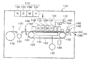
図1には、本発明の画像形成装置の一実施形態を示すインクジェット記録装置の全体構成図が示されている。同図に示すように、このインクジェット記録装置110は、黒(K),シアン(C),マゼンタ(M),イエロー(Y)の各インクに対応して設けられた複数のインクジェット記録ヘッド(以下、ヘッドという。)112K,112C,112M,112Yを有する印字部112と、各ヘッド112K,112C,112M,112Yに供給するインクを貯蔵しておくインク貯蔵/装填部114と、記録媒体としての記録紙Sを供給する給紙部118と、記録紙Sのカールを除去するデカール処理部120と、前記印字部112のノズル面(インク吐出面)に対向して配置され、記録紙Sの平面性を保持しながら記録紙Sを搬送するベルト搬送部122と、印字部112による印字結果を読み取る印字検出部124と、記録済みの記録紙(プリント物)を外部に排紙する排紙部126と、を備えている。なお、本明細書でいう「印字」とは、文字の印刷の他に画像の印刷も含む。
FIG. 1 is an overall configuration diagram of an ink jet recording apparatus showing an embodiment of an image forming apparatus of the present invention. As shown in the figure, the ink jet recording apparatus 110 includes a plurality of ink jet recording heads (hereinafter referred to as “ink jet recording heads”) corresponding to black (K), cyan (C), magenta (M), and yellow (Y) inks. A
インク貯蔵/装填部114は、各ヘッド112K、112C、112M、112Yに対応する色のインクを貯蔵するインクタンク13K,13C,13M,13Yを有し、各タンクは所要の管路を介してヘッド112K、112C、112M、112Yと連通されている。また、インク貯蔵/装填部114は、インク残量が少なくなるとその旨を報知する報知手段を備えるとともに、色間の誤装填を防止するための機構を有している。
The ink storage /
図1では、給紙部118の一例としてロール紙(連続用紙)のマガジンが示されているが、紙幅や紙質等が異なる複数のマガジンを併設してもよい。また、ロール紙のマガジンに代えて、又はこれと併用して、カット紙が積層装填されたカセットによって用紙を供給してもよい。
In FIG. 1, a magazine for rolled paper (continuous paper) is shown as an example of the
複数種類の記録媒体(メディア)を利用可能な構成にした場合、メディアの種類情報を記録したバーコード或いは無線タグなどの情報記録体をマガジンに取り付け、その情報記録体の情報を所定の読取装置によって読み取ることで、使用される記録媒体の種類(メディア種)を自動的に判別し、メディア種に応じて適切なインク吐出を実現するようにインク吐出制御を行うことが好ましい。 When a plurality of types of recording media (media) can be used, an information recording body such as a barcode or a wireless tag that records media type information is attached to a magazine, and information on the information recording body is read by a predetermined reader. It is preferable to automatically determine the type of recording medium to be used (media type) and to perform ink ejection control so as to realize appropriate ink ejection according to the media type.
給紙部118から送り出される記録紙Sはマガジンに装填されていたことによる巻きクセが残り、カールする。このカールを除去するために、デカール処理部120においてマガジンの巻きクセ方向と逆方向に加熱ドラム130で記録紙Sに熱を与える。このとき、多少印字面が外側に弱いカールとなるように加熱温度を制御するとより好ましい。
The recording paper S delivered from the
ロール紙を使用する装置構成の場合、図1のように、裁断用のカッター128が設けられており、該カッター128によってロール紙は所望のサイズにカットされる。なお、カット紙を使用する場合には、カッター128は不要である。
In the case of an apparatus configuration using roll paper, a
デカール処理後、カットされた記録紙Sは、ベルト搬送部122へと送られる。ベルト搬送部122は、ローラ131、132間に無端状のベルト133が巻き掛けられた構造を有するように構成されている。
After the decurling process, the cut recording paper S is sent to the
ベルト133は、記録紙Sの幅よりも広い幅寸法を有しており、ベルト面には多数の吸引穴(不図示)が形成されている。同図に示されるように、ローラ131、132間に掛け渡されたベルト133の内側において印字部112のノズル面、及び印字検出部124のセンサ面に対向する位置には吸着チャンバ134が設けられており、この吸着チャンバ134をファン135で吸引して負圧にすることによって記録紙Sがベルト133上に吸着保持される。なお、吸引吸着方式に代えて、静電吸着方式を採用してもよい。
The
ベルト133が巻かれているローラ131、132の少なくとも一方に図示しないモータの動力が伝達されることにより、ベルト133は図1上の時計回り方向に駆動され、ベルト133上に保持された記録紙Sは図1の左から右へと搬送される。
The power of a motor (not shown) is transmitted to at least one of the
縁無しプリント等を印字するとベルト133上にもインクが付着するので、ベルト133の外側の所定位置(印字領域以外の適当な位置)にベルト清掃部136が設けられている。ベルト清掃部136の構成について詳細は図示しないが、例えば、ブラシ・ロール、吸水ロール等をニップする方式、清浄エアーを吹き掛けるエアーブロー方式、或いはこれらの組合せなどがある。清掃用ロールをニップする方式の場合、ベルト線速度とローラ線速度を変えると清掃効果が大きい。
Since ink adheres to the
なお、ベルト搬送部122に代えて、ローラ・ニップ搬送機構を用いる態様も考えられるが、印字領域をローラ・ニップ搬送すると、印字直後に用紙の印字面をローラが接触するので画像が滲み易いという問題がある。したがって、本例のように、印字領域では画像面を接触させない吸着ベルト搬送が好ましい。
Although a mode using a roller / nip conveyance mechanism in place of the
ベルト搬送部122により形成される用紙搬送路上において印字部112の上流側には、加熱ファン140が設けられている。加熱ファン140は、印字前の記録紙Sに加熱空気を吹き付け、記録紙Sを加熱する。印字直前に記録紙Sを加熱しておくことにより、インクが着弾後乾き易くなる。
A
印字部112の各ヘッド112K、112C、112M、112Yは、当該インクジェット記録装置110が対象とする記録紙Sの最大紙幅に対応する長さを有し、そのノズル面には最大サイズの記録紙Sの少なくとも一辺を超える長さ(描画可能範囲の全幅)にわたりインク吐出用のノズルが複数配列されたフルライン型のヘッドとなっている。
Each
ヘッド112K、112C、112M、112Yは、記録紙Sの送り方向に沿って上流側から黒(K)、シアン(C)、マゼンタ(M)、イエロー(Y)の色順に配置され、それぞれのヘッド112K、112C、112M、112Yが記録紙Sの搬送方向と略直交する方向に沿って延在するように固定設置される。
The
ベルト搬送部122により記録紙Sを搬送しつつ各ヘッド112K、112C、112M、112Yからそれぞれ異色のインクを吐出することにより記録紙S上にカラー画像を形成し得る。
A color image can be formed on the recording paper S by ejecting different colors of ink from the
このように、紙幅の全域をカバーするノズル列を有するフルライン型のヘッド112K、112C、112M、112Yを色別に設ける構成によれば、紙送り方向(副走査方向)について記録紙Sと印字部112を相対的に移動させる動作を1回行うだけで(すなわち1回の副走査で)、記録紙Sの全面に画像を記録することができる。これにより、記録ヘッドが紙搬送方向と直交する方向に往復動作するシャトル型ヘッドに比べて高速印字が可能であり、生産性を向上させることができる。 As described above, according to the configuration in which the full-line heads 112K, 112C, 112M, and 112Y having nozzle rows that cover the entire width of the paper are provided for each color, the recording paper S and the printing unit in the paper feeding direction (sub-scanning direction). An image can be recorded on the entire surface of the recording paper S by performing the operation of relatively moving the 112 once (that is, by one sub-scan). Thereby, it is possible to perform high-speed printing as compared with a shuttle type head in which the recording head reciprocates in a direction orthogonal to the paper transport direction, and productivity can be improved.
本例では、KCMYの標準色(4色)の構成を例示したが、インク色や色数の組合せについては本実施形態に限定されず、必要に応じて淡インク、濃インク、特別色インクを追加してもよい。例えば、ライトシアン、ライトマゼンタなどのライト系インクを吐出するインクジェットヘッドを追加する構成も可能である。また、各色ヘッドの配置順序も特に限定はない。 In this example, the configuration of KCMY standard colors (four colors) is illustrated, but the combination of ink colors and the number of colors is not limited to this embodiment, and light ink, dark ink, and special color ink are used as necessary. May be added. For example, it is possible to add an ink jet head that discharges light ink such as light cyan and light magenta. Also, the arrangement order of the color heads is not particularly limited.
図1に示した印字検出部124は、印字部112の打滴結果を撮像するためのイメージセンサ(ラインセンサ又はエリアセンサ)を含み、該イメージセンサによって読み取った打滴画像からノズルの目詰まりや着弾位置誤差などの吐出特性をチェックする手段として機能する。
The
本例の印字検出部124には、受光面に複数の受光素子(光電変換素子)が2次元配列されてなるCCDエリアセンサを好適に用いることができる。エリアセンサは、少なくとも各ヘッド112K、112C、112M、112Yによるインク吐出幅(画像記録幅)の全域を撮像できる撮像範囲を有しているものとする。1つのエリアセンサで所要の撮像範囲を実現してもよいし、複数のエリアセンサを組み合わせて(繋ぎ合わせて)所要の撮像範囲を確保してもよい。或いはまた、エリアセンサを移動機構(不図示)によって支持し、エリアセンサを移動(走査)させることによって所要の撮像範囲を撮像する構成も可能である。
For the
また、エリアセンサに代えてラインセンサを用いることも可能である。この場合、ラインセンサは、少なくとも各ヘッド112K、112C、112M、112Yによるインク吐出幅(画像記録幅)よりも幅の広い受光素子列(光電変換素子列)を有する構成が好ましい。
Also, a line sensor can be used instead of the area sensor. In this case, it is preferable that the line sensor has a light receiving element array (photoelectric conversion element array) wider than at least the ink ejection width (image recording width) by each of the
このように、印字検出部124は、イメージセンサを含むブロックであり、記録紙Sに印字された画像を読み取り、所要の信号処理などを行って印字状況(吐出の有無、着弾位置誤差、ドット形状、光学濃度など)を検出し、その検出結果を図示しないプリント制御部及びシステムコントローラに提供する。
As described above, the
印字検出部124の後段には後乾燥部142が設けられている。後乾燥部142は、印字された画像面を乾燥させる手段であり、例えば、加熱ファンが用いられる。印字後のインクが乾燥するまでは印字面と接触することは避けたほうが好ましいので、熱風を吹き付ける方式が好ましい。
A
多孔質のペーパーに染料系インクで印字した場合などでは、加圧によりペーパーの孔を塞ぐことでオゾンなど、染料分子を壊す原因となるものと接触することを防ぐことで画像の耐候性がアップする効果がある。 When printing on porous paper with dye-based ink, the weather resistance of the image is improved by preventing contact with ozone or other things that cause dye molecules to break by pressurizing the paper holes with pressure. There is an effect to.
後乾燥部142の後段には、加熱・加圧部144が設けられている。加熱・加圧部144は、画像表面の光沢度を制御するための手段であり、画像面を加熱しながら所定の表面凹凸形状を有する加圧ローラ145で加圧し、画像面に凹凸形状を転写する。
A heating /
こうして生成されたプリント物は排紙部126から排出される。本来プリントすべき本画像(目的の画像を印刷したもの)とテスト印字とは分けて排出することが好ましい。このインクジェット記録装置110では、本画像のプリント物と、テスト印字のプリント物とを選別してそれぞれの排出部126A、126Bへと送るために排紙経路を切り換える不図示の選別手段が設けられている。
The printed matter generated in this manner is outputted from the
なお、大きめの用紙に本画像とテスト印字とを同時に並列に形成する場合は、カッター148によってテスト印字の部分を切り離す。また、図には示さないが、本画像の排出部126Aには、オーダー別に画像を集積するソーターが設けられる。
When the main image and the test print are simultaneously formed in parallel on a large sheet, the test print portion is separated by the
図2は、前述したインクジェット記録装置110におけるインク供給系の内部構造を簡略化して示したものである。なお、各ヘッド112K,112C,112M,112Y、及び、対応する色のインクを貯蔵するインクタンク13K,13C,13M,13Yは同様の構成とされているため、ここでは1つをヘッド112、インクタンク13として説明する。
FIG. 2 shows a simplified internal structure of the ink supply system in the ink jet recording apparatus 110 described above. Since each of the
インクタンク13は、管路13Aを介してバッファータンク14と連結されている。バッファータンク14は、大気に開放されている。管路13Aには、ポンプ13B及びバルブ13Cが設けられている。インクタンク13に貯蔵されたインクは、ポンプ13Bを駆動させることにより、バッファータンク14へ供給される。バッファータンク14には、インクタンク13からのインク供給により、所定量のインクが貯留されている。
The
バッファータンク14は、供給タンク40と第1流路22を介して連結されている。また、バッファータンク14は、回収タンク50と第2流路32を介して連結されている。第1流路22には、供給タンク40とバッファータンク14との間での送液を行う第1ポンプ24が設けられ、第1ポンプ24とバッファータンク14との間にフィルタFが設けられている。第2流路32には、回収タンク50とバッファータンク14との間での送液を行う第2ポンプ34が設けられている。供給タンク40は、供給路23を介してヘッド112に連通され、回収タンク50は、回収路33を介してヘッド112に連通されている。
The
供給タンク40の内部は、第1弾性膜44によって、第1液体室46と第1気体室48とに区画されている。回収タンク50の内部は、第2弾性膜54によって、第2液体室56と第2気体室58に区画されている。第1流路22及び供給路23は、供給タンク40の第1液体室46へ連通されており、第2流路32及び回収路33は、回収タンク50の第2液体室56へ連通されている。供給タンク40及び回収タンク50の詳細については後述する。
The inside of the
ヘッド112は、複数のヘッドバーに分割されており(図2では3分割)、各々のヘッドバーにインクを供給するための供給口23A、および、インクを排出するための排出口33Aが構成されている。供給路23は、供給口23Aの手前で分岐され、各々の供給口23Aから各ヘッドバーへインクが供給される。また、各排出口33Aからの各々の回収路33は、回収タンク50の手前で合流されている。
The
なお、本実施形態では、記録ヘッドが複数のヘッドバーに分割されている例について説明したが、記録ヘッドは分割されず単体であってもよい。 In this embodiment, the example in which the recording head is divided into a plurality of head bars has been described. However, the recording head may be a single unit without being divided.
供給路23には、供給口23A毎に分岐された各々にバルブV1Aが設けられると共に、分岐されていない側にバルブV1が設けられている。回収路33には、排出口33A毎に分岐された各々にバルブV2が設けられている。
In the
バッファータンク14、第1流路22、供給タンク40、供給路23により供給系流路が構成され、回収路33、回収タンク50、及び、第2流路32により、回収系流路が構成されている。供給系流路、ヘッド112、回収系流路、及び、バッファータンク14により、インク供給系の循環路20が構成されている。
The
次に、供給タンク40及び回収タンク50について説明する。
Next, the
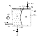
図3(A)に示すように、供給タンク40は円筒状の筐体42を備え、筐体42内の空間は、第1弾性膜44によって第1液体室46と第1気体室48とに区画されている。第1弾性膜44は、円板状とされ、円柱形とされた筐体42の内部を軸方向で分割するように配置されている。第1弾性膜44は、弾性変形可能な材料で構成されており、ゴム、熱可塑性エラストマー、などで構成することが好ましい。特に、フッ素ゴム、NBRは好適に用いることができる。
As shown in FIG. 3A, the
第1弾性膜44の第1気体室48側の表面には、貼付抑制部材として複数の突起44Aが形成されている。図4(A)に示すように、突起44Aは円形状とされた第1弾性膜44の表面のほぼ全面に形成されている。突起44Aは、図4(B)に示すように、先端側が曲面形状とされ、第1弾性膜44と一体的に同一材料で構成されている。なお、突起44Aは、図4(C)に示すように、第1弾性膜44と別体とされて別材料で構成されていてもよい。
On the surface of the first
第1液体室46の加圧によって、第1弾性膜44が第1気体室48側へ膨らんで、第1気体室48の内壁48Aに接着された際に、第1弾性膜44が変形して複数の突起44Aの間に構成される隙間からはみ出し、第1気体室48の内壁48Aに密着されることのないように(図5参照)、複数の突起44Aの各々の間隔、硬度、大きさ、第1弾性膜44の硬度、厚み、が設定される。
The first
なお、第1弾性膜44と突起44Aとを異なる材料で構成する場合には、突起44Aの粘着性を第1弾性膜44よりも低くすることが好ましく、突起44Aの硬度を第1弾性膜44よりも高くすることが好ましい。また、突起44Aに貼付防止用のコーティング(フッ素コーティングなど)を施してもよい。
In the case where the first
第1液体室46にはインクが貯留され、第1流路22、供給路23と連通されている。供給タンク40には、第1圧力検出器43が接続されている。第1圧力検出器43は、第1液体室46内の圧力を検出可能とされている。第1圧力検出器43は、第1液体室46の圧力を直接検出するものであっても、第1気体室48の圧力を検出して間接的に第1液体室46の圧力を検出するものであってもよい。
Ink is stored in the first
第1気体室48には、気体が充填され、第1気体室48を大気へ開放する開放管49が連通されている。開放管49には開放管49を開閉するバルブ49Vが設けられている。
The
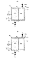
図3(B)に示すように、回収タンク50は供給タンク40とほぼ同一の形状とされ、筐体42に対応する筐体52、第1弾性膜44に対応する第2弾性膜54、突起44Aに対応する突起54A、第1液体室46に対応する第2液体室56、第1気体室48に対応する第2気体室58を有している。第2液体室56にはインクが貯留され、第2流路32、回収路33と連通されている。回収タンク50には、第2圧力検出器53が接続されている。第2圧力検出器53は、第2液体室56内の圧力を検出可能とされている。第2圧力検出器53は、第2液体室56の圧力を直接検出するものであっても、第2気体室58の圧力を検出して間接的に第2液体室56の圧力を検出するものであってもよい。
As shown in FIG. 3B, the
第2気体室58には、気体が充填され、第2気体室58を大気へ開放する開放管59が連通されている。開放管59には開放管59を開閉するバルブ59Vが設けられている。
The
次に、インクの循環動作について説明する。 Next, the ink circulation operation will be described.
インクジェット記録装置110の起動中は、循環路20では、常時、以下のようにしてインクの循環が行われている。
During the startup of the ink jet recording apparatus 110, the circulation of the ink is always performed in the
循環路20では、インク供給側の圧力をインク回収側の圧力よりも所定量だけ高く設定することにより、供給タンク40側からヘッド112を経て回収タンク50側へインクが送液される。ここで、第1液体室46内の圧力をPin、第2液体室56内の圧力をPout、インクが吐出されるノズルの背圧(負圧)をPnzlとすると、Pin+Hin>Pnzl>Pout+Hout(mmH2O)として(Hinは、ノズル面と第1圧力検出器43との間の高低差により生じる圧力差(水頭圧)、Houtは、ノズル面と第2圧力検出器53との間の高低差により生じる圧力差(水頭圧))、ノズルに所定の背圧を付与する。供給タンク40の第1液体室46、及び、回収タンク50の第2液体室56の圧力は、第1圧力検出器43により検出された第1液体室46内の圧力、及び、第2圧力検出器53により検出された第2液体室56内の圧力に基づいて、第1ポンプ24、第2ポンプ34により、第1液体室46、第2液体室56、の圧力が、各々所定の圧力Pin、Poutとなるように制御され、これにより、循環路20内でインクが循環する。
In the
このとき、第1弾性膜44、及び、第2弾性膜54は、第1弾性部材45、第2弾性部材55と非接触の位置に配置されている。また、開放管49、59のバルブ49V、59Vは、閉鎖されている。一方、循環路20に設けられたバルブV1、V1A、V2は、開放されている。
At this time, the first
上記のように、インクを循環させることにより、ノズルでのインク増粘を防止して、良好なインクの吐出状態を長時間維持して、高い印刷品質を長時間維持することができる。 As described above, by circulating the ink, it is possible to prevent ink thickening at the nozzle, maintain a good ink discharge state for a long time, and maintain a high print quality for a long time.
また、第1ポンプ24、第2ポンプ34の動作による圧力変動が、第1弾性膜44、第2弾性膜54により吸収され、ヘッド112内のノズルに於ける圧力変動が抑制されるため、ノズルの背圧を一定に維持することができ、高い印刷品質を維持することができる。
Further, pressure fluctuations due to the operations of the
なお、通常の印刷時には、第1液体室46内は負圧とされ、図6に示すように、第1弾性膜44は、第1液体室46側へ引かれている。また、印刷時及び後述のメンテナンス時以外には、図3に示すように、第1弾性膜44及び第2弾性膜54は、弾性変形されず、平坦状態とされている。
During normal printing, the inside of the first
次に、加圧メンテナンスについて説明する。加圧メンテナンスでは、ノズルの目詰まりなどを解消するために、ノズルから加圧状態でインクを吐出させるものである。 Next, pressurization maintenance will be described. In pressure maintenance, ink is ejected from the nozzles in a pressurized state in order to eliminate clogging of the nozzles.
まず、供給タンク40内を加圧する加圧工程を実行する。バルブ49Vを開放して第1気体室48を大気に開放すると共に、バルブV1を閉鎖して、第1ポンプ24を作動させ、供給タンク40内を加圧する。これにより、図7(A)に示すように、第1弾性膜44が第1気体室48側へ張り出して、内壁48Aに密着する。第1ポンプ24では、第1液体室46内が所定の目標圧力となるまで加圧する。
First, the pressurization process which pressurizes the inside of the
第1液体室46が所定の目標圧力とされたら、次に、インク排出工程を実行する。
When the first
まず、インク排出を実施する1個以上のヘッド112に対応するバルブV1Aを開放する。第1ポンプ24を作動させた状態で、バルブ49Vを閉鎖して、その後バルブV1を開放する。すると、第1液体室46からバルブV1Aが開放されたヘッド112へインクが流出する。このとき液量が減少するため、第1弾性膜44が、図7(A)に示される位置から、第1液体室46側へわずかに戻った図7(B)に示される位置へ移動する。
First, the valve V1A corresponding to one or
このとき、突起44Aにより第1弾性膜44の内壁48Aへの貼り付きが抑制されているので、第1弾性膜44をスムーズに移動させることができ、目標とする加圧メンテナンスの圧力プロファイルを正確に実現することができる。
At this time, since the sticking of the first
また、第1弾性膜44が貼り付いて不均一に変形することも抑制されているので、第1弾性膜44に対して部分的に過剰な引っ張りが生じるなどの不具合が発生しにくく、第1弾性膜44の長寿命化を図ることができる。
In addition, since the first
また、突起44Aは、内壁48Aに押し当てられている際に弾性変形しているので、第1弾性膜44が第1液体室46側へ戻る際の初期段階においては、突起44Aが内壁48Aに接したまま、その復元力により第1液体室46側へ移動する。したがって、突起44Aが内壁48Aに接している間の第1液体室46の圧力変化を緩やかにすることができる。
Further, since the
また、バルブ49Vを閉鎖することにより、第1気体室48がダンパとして作用するので、第1液体室46の圧力が急速に低下することを防止することができる。
Further, by closing the
図8には、上記のインク排出動作における時間経過と供給タンク40内の圧力との関係が示されている。破線Bは、本実施形態で設けた第1弾性部材45を設けず、第1弾性膜44が直接筐体42に接触する比較例である。比較例では、バルブV1の開放(C)時点の直後に第1弾性膜44が筐体42に密着した状態から、徐々に第1液体室46側へ移動する。このとき、第1弾性膜44は内壁48Aに少なくとも一部が貼付されている(図9参照)。そして、(D)まで圧力が低下する。その後、第1弾性膜44が内壁48Aから離れて、第1液体室46側へ急激に移動し、第1液体室46の容積が小さくなる。これにより、第1液体室46の圧力は一時的に(E)まで上昇する。その後、圧力が下降し、第1ポンプ24による加圧動作による所定のメンテナンス用圧力となる。
FIG. 8 shows the relationship between the passage of time in the ink discharge operation and the pressure in the
一方、本実施形態の供給タンク40では、実線Aで示されるように、バルブV1の開放(C)時点の直後に圧力の低下があるものの、破線Bと比較して緩やかであり、所定のメンテナンス用圧力まで緩やかに圧力が低下する。
On the other hand, in the
このように、本実施形態によれば、突起44Aを設けているので、急激な圧力変動が防止されて緩やかに圧力低下が行われる。したがって、目標とする加圧メンテナンスのための圧力プロファイルをより正確に実施することができる。
Thus, according to this embodiment, since the
なお、本実施形態では、供給タンク40側を用いて加圧メンテナンスを行う例について説明したが、加圧メンテナンスは、回収タンク50側を用いて同様の手順で行ってもよい。
In the present embodiment, an example in which pressurization maintenance is performed using the
なお、本実施形態では、突起44Aの先端を曲面形状としたが、突起44Aは他の形状とすることもできる。例えば、図10(A)に示すように、先端が尖った円錐形状の突起44Bとしてもよいし、図10(B)に示すように、先端が平坦な台錐形状の突起44Cとしてもよい。また、図10(C)に示すように、繊維状の突起44Dとしてもよい。さらに、突起は、図10(D)に示すように、先端部分44Eと基端部分44Fとを異なる材料で構成して、硬度、粘着性を変化させてもよい。この場合には、先端部分の硬度は基端部分よりも高くし、先端部分の粘着性は基端部分よりも低くすることが好ましい。
In the present embodiment, the tip of the
また、本実施形態では、第1弾性膜44に突起44Aを形成し、第2弾性膜54に突起54Aを形成したが、突起は、図11(A)に示すように、供給タンク40の内壁48A側、図11(B)に示すように、回収タンク50の内壁58A側、に形成してもよい。
Further, in this embodiment, the
また、本実施形態では、第1弾性膜44、及び、第2弾性膜54の貼付抑制部材として、突起を形成した例について説明したが、貼付抑制部材としては、他の構成を採用することもできる。例えば、第1弾性膜44、及び、第2弾性膜54、内壁48A、58Aの表面を租面化したり、フッ素などの樹脂でコーティングしたりして構成してもよい
Moreover, although this embodiment demonstrated the example which formed the processus | protrusion as a sticking suppression member of the 1st
また、本実施形態では、ヘッド112とバッファータンク14との間に回収タンク50を設けたが、回収タンク50は必ずしも必要ではなく、ヘッド112から直接バッファータンク14へインクを送出してもよい。
In this embodiment, the
また、本実施形態では、画像形成装置としてインクを用いたインクジェット記録装置を例に説明したが、本発明は、インクジェット記録装置に限定されず、液体トナーやその他の液体を用いて画像を形成する画像形成装置に適用することもできる。 In this embodiment, an ink jet recording apparatus using ink as an image forming apparatus has been described as an example. However, the present invention is not limited to an ink jet recording apparatus, and an image is formed using liquid toner or other liquid. It can also be applied to an image forming apparatus.
13 インクタンク
14 バッファータンク
20 インク循環路
22 第1流路
23 供給路
24 第1ポンプ
32 第2流路
33 回収路
34 第2ポンプ
40 供給タンク
44 第1弾性膜
44A 突起
46 第1液体室
48 第1気体室
50 回収タンク
54 第2弾性膜
54A 突起
56 第2液体室
58 第2気体室
110 インクジェット記録装置
112 ヘッド
S 記録紙
13
Claims (3)
前記記録ヘッドへ供給する画像形成用の液体を貯留するタンクと、
前記タンクに貯留された液体を前記記録ヘッドへ供給する供給路と、
前記タンク内を、前記液体を貯留する液体室と気体が充填される気体室とに区画する弾性変形可能な弾性膜と、
前記液体室内の液圧を調整する液圧調整手段と、
前記弾性膜と前記タンクの前記気体室側の内壁との貼り付きを抑制する貼付抑制部材と、
を備え、
前記貼付抑制部材は、前記弾性膜の前記気体室側の表面に形成された複数の突起を含んで形成され、前記複数の突起は前記弾性膜が該複数の突起の間に構成される隙間からはみ出して前記気体室の内壁に密着されないように、前記弾性膜の全面に形成され、前記弾性膜よりも粘着性が低く硬度が高いこと、を特徴とする画像形成装置。 A recording head for recording an image by discharging droplets onto a recording medium;
A tank for storing an image forming liquid to be supplied to the recording head;
A supply path for supplying the liquid stored in the tank to the recording head;
An elastically deformable elastic membrane that divides the inside of the tank into a liquid chamber storing the liquid and a gas chamber filled with gas;
Hydraulic pressure adjusting means for adjusting the hydraulic pressure in the liquid chamber;
A sticking suppression member that suppresses sticking between the elastic membrane and the inner wall of the tank on the gas chamber side;
With
The sticking suppression member is formed including a plurality of protrusions formed on a surface of the elastic film on the gas chamber side, and the plurality of protrusions are formed from gaps in which the elastic film is formed between the plurality of protrusions. An image forming apparatus , wherein the image forming apparatus is formed on the entire surface of the elastic film so as not to protrude and adhere to the inner wall of the gas chamber, and has lower adhesiveness and higher hardness than the elastic film .
Priority Applications (1)
| Application Number | Priority Date | Filing Date | Title |
|---|---|---|---|
| JP2008085517A JP5079570B2 (en) | 2008-03-28 | 2008-03-28 | Image forming apparatus |
Applications Claiming Priority (1)
| Application Number | Priority Date | Filing Date | Title |
|---|---|---|---|
| JP2008085517A JP5079570B2 (en) | 2008-03-28 | 2008-03-28 | Image forming apparatus |
Publications (2)
| Publication Number | Publication Date |
|---|---|
| JP2009234150A JP2009234150A (en) | 2009-10-15 |
| JP5079570B2 true JP5079570B2 (en) | 2012-11-21 |
Family
ID=41248702
Family Applications (1)
| Application Number | Title | Priority Date | Filing Date |
|---|---|---|---|
| JP2008085517A Expired - Fee Related JP5079570B2 (en) | 2008-03-28 | 2008-03-28 | Image forming apparatus |
Country Status (1)
| Country | Link |
|---|---|
| JP (1) | JP5079570B2 (en) |
Families Citing this family (3)
| Publication number | Priority date | Publication date | Assignee | Title |
|---|---|---|---|---|
| CN102812064B (en) | 2010-03-26 | 2014-10-29 | 道康宁公司 | Preparation of lignocellulosic products |
| JP6468900B2 (en) * | 2015-03-18 | 2019-02-13 | セーレン株式会社 | Inkjet recording device |
| CN116533520B (en) * | 2023-06-25 | 2026-03-03 | 浙江闪铸集团有限公司 | Circulation ink supply system suitable for 3D ink jet printing and control method thereof |
Family Cites Families (10)
| Publication number | Priority date | Publication date | Assignee | Title |
|---|---|---|---|---|
| JPH0392421U (en) * | 1990-01-06 | 1991-09-20 | ||
| JPH07121583B2 (en) * | 1991-12-06 | 1995-12-25 | セイコーエプソン株式会社 | Inkjet type serial printer |
| JPH06115092A (en) * | 1992-09-30 | 1994-04-26 | Fuji Electric Co Ltd | Inkjet recording head |
| JP2002211003A (en) * | 2001-01-22 | 2002-07-31 | Seiko Epson Corp | Ink jet recording apparatus and pressure damper mounting method thereof |
| JP2002231614A (en) * | 2001-02-05 | 2002-08-16 | Canon Inc | Peeling patch, peeling device and method |
| JP2003094681A (en) * | 2001-09-27 | 2003-04-03 | Sii Printek Inc | Inkjet printer |
| JP2003300336A (en) * | 2002-04-09 | 2003-10-21 | Seiko Epson Corp | Ink flow path valve and ink jet recording apparatus using the same |
| JP2004074462A (en) * | 2002-08-12 | 2004-03-11 | Sii Printek Inc | Air damper, inkjet head and inkjet recorder |
| JP2004291620A (en) * | 2002-11-19 | 2004-10-21 | Seiko Epson Corp | Liquid injection device |
| JP4570850B2 (en) * | 2003-06-24 | 2010-10-27 | エスアイアイ・プリンテック株式会社 | Pressure buffer and droplet jet recording apparatus |
-
2008
- 2008-03-28 JP JP2008085517A patent/JP5079570B2/en not_active Expired - Fee Related
Also Published As
| Publication number | Publication date |
|---|---|
| JP2009234150A (en) | 2009-10-15 |
Similar Documents
| Publication | Publication Date | Title |
|---|---|---|
| JP5047108B2 (en) | Droplet discharge device | |
| US8079693B2 (en) | Liquid ejecting device | |
| JP4971942B2 (en) | Inkjet recording apparatus and recording method | |
| EP1518683B1 (en) | Droplet discharge head and inkjet recording apparatus | |
| JP4963572B2 (en) | Liquid supply apparatus, image forming apparatus, and liquid supply method | |
| JP2009234151A (en) | Image forming apparatus | |
| JP3944858B2 (en) | Image forming apparatus | |
| JP5079570B2 (en) | Image forming apparatus | |
| JP3774902B2 (en) | Droplet discharge head and inkjet recording apparatus | |
| JP5025008B2 (en) | Ink jet recording apparatus and ink supply method | |
| JP2009233979A (en) | Abnormality determining device and abnormality determining method of liquid ejecting device | |
| JP4933201B2 (en) | Liquid supply method | |
| JP3987961B2 (en) | Inkjet recording apparatus and inkjet recording method | |
| JP2005231351A (en) | Inkjet recording apparatus | |
| JP4761130B2 (en) | Liquid ejecting apparatus and image forming apparatus | |
| JP4902971B2 (en) | Liquid discharge head | |
| JP3903089B2 (en) | Deaeration device, liquid discharge device, and ink jet recording apparatus | |
| JP2006264170A (en) | Liquid transfer pipe and image forming device | |
| JP3906846B2 (en) | Ink jet recording head and ink jet recording apparatus provided with the same | |
| JP2008137341A (en) | Droplet discharge head and image forming apparatus | |
| JP2007237689A (en) | Liquid ejection apparatus, image forming apparatus, and maintenance method for liquid ejection apparatus | |
| JP2005186545A (en) | Droplet discharging device | |
| US20060214959A1 (en) | Liquid droplet ejection apparatus | |
| JP2007050672A (en) | Method and apparatus for discharging liquid droplet | |
| JP2007237690A (en) | Liquid ejection apparatus, image forming apparatus, and maintenance method for liquid ejection apparatus |
Legal Events
| Date | Code | Title | Description |
|---|---|---|---|
| A621 | Written request for application examination |
Free format text: JAPANESE INTERMEDIATE CODE: A621 Effective date: 20100712 |
|
| A977 | Report on retrieval |
Free format text: JAPANESE INTERMEDIATE CODE: A971007 Effective date: 20111216 |
|
| A131 | Notification of reasons for refusal |
Free format text: JAPANESE INTERMEDIATE CODE: A131 Effective date: 20120110 |
|
| A521 | Written amendment |
Free format text: JAPANESE INTERMEDIATE CODE: A523 Effective date: 20120307 |
|
| A131 | Notification of reasons for refusal |
Free format text: JAPANESE INTERMEDIATE CODE: A131 Effective date: 20120327 |
|
| A521 | Written amendment |
Free format text: JAPANESE INTERMEDIATE CODE: A523 Effective date: 20120516 |
|
| TRDD | Decision of grant or rejection written | ||
| A01 | Written decision to grant a patent or to grant a registration (utility model) |
Free format text: JAPANESE INTERMEDIATE CODE: A01 Effective date: 20120807 |
|
| A01 | Written decision to grant a patent or to grant a registration (utility model) |
Free format text: JAPANESE INTERMEDIATE CODE: A01 |
|
| A61 | First payment of annual fees (during grant procedure) |
Free format text: JAPANESE INTERMEDIATE CODE: A61 Effective date: 20120829 |
|
| FPAY | Renewal fee payment (event date is renewal date of database) |
Free format text: PAYMENT UNTIL: 20150907 Year of fee payment: 3 |
|
| R150 | Certificate of patent or registration of utility model |
Ref document number: 5079570 Country of ref document: JP Free format text: JAPANESE INTERMEDIATE CODE: R150 Free format text: JAPANESE INTERMEDIATE CODE: R150 |
|
| R250 | Receipt of annual fees |
Free format text: JAPANESE INTERMEDIATE CODE: R250 |
|
| R250 | Receipt of annual fees |
Free format text: JAPANESE INTERMEDIATE CODE: R250 |
|
| R250 | Receipt of annual fees |
Free format text: JAPANESE INTERMEDIATE CODE: R250 |
|
| R250 | Receipt of annual fees |
Free format text: JAPANESE INTERMEDIATE CODE: R250 |
|
| LAPS | Cancellation because of no payment of annual fees |