JP5077818B2 - Automatic faucet - Google Patents
Automatic faucet Download PDFInfo
- Publication number
- JP5077818B2 JP5077818B2 JP2007278911A JP2007278911A JP5077818B2 JP 5077818 B2 JP5077818 B2 JP 5077818B2 JP 2007278911 A JP2007278911 A JP 2007278911A JP 2007278911 A JP2007278911 A JP 2007278911A JP 5077818 B2 JP5077818 B2 JP 5077818B2
- Authority
- JP
- Japan
- Prior art keywords
- sensor
- water discharge
- output
- automatic
- water
- Prior art date
- Legal status (The legal status is an assumption and is not a legal conclusion. Google has not performed a legal analysis and makes no representation as to the accuracy of the status listed.)
- Active
Links
Images


Description
本発明は、自動水栓に係り、特に、センサーによる自動吐水及び連続吐水の可能な自動水栓に関する。 The present invention relates to an automatic faucet, and more particularly to an automatic faucet capable of automatic water discharge and continuous water discharge by a sensor.
特許文献1には、吐水口に差し出された手などをセンサーにて検知して自動で吐水する自動モードの機能を備えた自動水栓が開示されている。この自動水栓には、自動で吐水させる必要が無い時には、自動モードをオフにする自動モード切替スイッチが設けられている。さらに、この自動水栓には、連続吐水スイッチが設けられており、その連続吐水スイッチがオンになると、自動モードがキャンセルされ、連続して吐水されるようになっている。
しかしながら、特許文献1の自動水栓では、連続吐水スイッチが、使用者が直接操作する接触型のスイッチであるため、連続吐水をさせるために使用者が濡れた手で操作する必要があり、その操作は面倒であった。
これに対し、特許文献1の自動水栓に、非接触型のセンサーによる連続吐水スイッチを適用して、操作の手間を省くことが考えられる。この場合、特許文献1の自動水栓では、非接触型の連続吐水用のセンサーが手を検知したときに、自動モードがキャンセルされる。従って、使用者の意思に反して誤って連続吐水のセンサー感知領域に手が移動した場合であっても自動モードがキャンセルされ、折角、節水のために自動モードにて水栓を使用中であっても、連続吐水されてしまう。即ち、自動吐水センサーの検知領域から手が離れても、吐水が連続することになり、節水することが出来ない使い勝手が悪いものとなってしまう。
However, in the automatic faucet of
On the other hand, it can be considered that the continuous water discharge switch using a non-contact type sensor is applied to the automatic faucet of
本発明は、上述した従来技術の問題点を解決するためになされたものであり、より確実に節水することが出来る自動水栓を提供することを目的とする。 The present invention has been made to solve the above-described problems of the prior art, and an object thereof is to provide an automatic faucet that can save water more reliably.
上記の目的を達成するために本発明による自動水栓によれば、吐水口に至る吐水経路に設けられた弁装置と、吐水口付近の所定のセンサーエリアをセンシングし、そのセンサーエリアに差し出された人の手等を感知している間第1出力を発生し続ける自動吐水用の第1感知部と、この第1感知部とは異なるセンサーエリアをセンシングし、そのセンサーエリアに差し出された人の手等を感知するたびに第2出力を発生する連続吐水用の第2感知部と、第1感知部からの第1出力を検知している間は弁装置を開にして吐水させ、第1感知部からの第1出力を検知していない間は弁装置を閉にして吐水を停止する自動吐水モードと、第2感知部からの第2出力を検知すると弁装置を開にし、次の第2感知部からの第2出力があるまで弁装置を継続して開にする連続吐水モードと、を生じさせる第1制御手段と、自動吐水モードをオン又はオフに切り替える切替出力を発生する切替手段と、自動吐水モードがオンであり且つ第1感知部からの第1出力を検知している間で弁装置が開となり吐水している状態において、第2感知部からの第2出力を検知すると、弁装置を閉弁すると共に自動吐水モードをオフにする第2制御手段と、を有することを特徴としている。
In order to achieve the above object, the automatic faucet according to the present invention senses a valve device provided in a water discharge path to a water discharge port and a predetermined sensor area near the water discharge port, and sends it to the sensor area. A first sensing unit for automatic water discharge that continues to generate a first output while sensing the hand of a person who has been touched, and a sensor area different from the first sensing unit is sensed and sent to the sensor area A second sensor for continuous water discharge that generates a second output each time a person's hand is sensed, and the valve device is opened to discharge water while detecting the first output from the first sensor. While the first output from the first sensing unit is not detected, the valve device is closed to stop water discharge, and when the second output from the second sensing unit is detected, the valve device is opened. Continue the valve until there is a second output from the next second sensor A first control means for generating a continuous water discharge mode to be opened, a switching means for generating a switching output for switching the automatic water discharge mode on or off, an automatic water discharge mode is on and the first sensing unit When the second output from the second sensing unit is detected while the valve device is open and water is discharged while the first output is being detected, the valve device is closed and the automatic water discharge mode is turned off. And 2 control means.
このように構成された本発明においては、自動吐水モードがオンであり且つ第1感知部からの第1出力を検知している間で弁装置が開となり吐水している状態において、その自動水栓を使用している人が、誤って第2感知部のセンサーエリアに、その手などをかざしてしまった場合であっても、節水を図ることが出来る。即ち、本発明における第2制御手段によれば、第2感知部からの第2出力を検知しても、この第2出力に基づく連続吐水が行われず、弁装置を閉弁すると共に自動吐水モードをオフにする。このように第2感知部により第2出力を検知した際には吐水が停止するのである。そして、その後、第1感知部からの第1出力を検知しなくなった場合であっても、従来のように、連続吐水モードによる連続した吐水が行われず、節水を図ることが出来る。従って、自動吐水モードによる自動水栓の使用中に、自動吐水モードをオフにする、という使用者の意思を反映して、吐水が停止し、節水を図ることが出来る。これらの結果、無駄な吐水を確実に防止して、節水を図ることが出来る。
In the present invention configured as described above, the automatic water discharge mode is ON while the valve device is open and discharging water while the first output from the first sensing unit is detected. Even if a person using the stopper accidentally puts his hand over the sensor area of the second sensor, water can be saved. That is, according to the second control means of the present invention, even if the second output from the second sensing unit is detected, the continuous water discharge based on the second output is not performed, the valve device is closed and the automatic water discharge mode is performed. Turn off. Thus, water discharge stops when the second output is detected by the second sensing unit. And even if it is a case where the 1st output from a 1st sensing part is no longer detected after that, continuous water discharge by continuous water discharge mode is not performed like before, but water saving can be aimed at. Accordingly, reflecting the user's intention to turn off the automatic water discharge mode during use of the automatic water faucet in the automatic water discharge mode, water discharge stops and water saving can be achieved. As a result, it is possible to reliably prevent unnecessary water discharge and save water.
また、本発明において、好ましくは、さらに、自動吐水モードがオンであり且つ第1感知部からの第1出力を検知している間で弁装置が開となり吐水している状態において、切替手段による自動吐水モードをオフに切り替える切替出力を検知すると、第1感知部によるセンサーのセンシングを停止させる。
このように構成された本発明においては、自動吐水モードがオンであり且つ第1感知部からの第1出力を検知している間で弁装置が開となり吐水している状態において、切替手段による自動吐水モードをオフに切り替える切替出力を検知すると、第1感知部によるセンサーのセンシングを停止させるので、自動吐水モードをオフにする、という使用者の意思を反映して確実に吐水を停止させることが出来る。
Further, in the present invention, preferably, in the state where the automatic water discharge mode is on and the valve device is open and water is discharged while detecting the first output from the first sensing unit, the switching means When the switching output for switching the automatic water discharge mode off is detected, sensing of the sensor by the first sensing unit is stopped.
In the present invention configured as described above, when the automatic water discharge mode is on and the valve device is open and water is discharged while the first output from the first sensing unit is detected, the switching means When the switching output for switching the automatic water discharge mode off is detected, the sensing of the sensor by the first sensing unit is stopped, so that the water discharge is surely stopped reflecting the user's intention to turn off the automatic water discharge mode. I can do it.
また、本発明において、好ましくは、さらに、自動吐水モードがオンであり且つ第1感知部からの第1出力を検知している間で弁装置が開となり吐水している状態において、第2感知部からの第2出力を検知した場合には、第2制御手段により弁装置が閉弁されると共に自動吐水モードがオフにされ、このときに第1感知部によるセンサーのセンシングを継続させ、その継続状態において第1感知部からの第1出力の発生を検知しなくなると、自動吐水モードをオンに復帰させ、次の第1感知部による第1出力を検知すると弁装置を開にして吐水させる第4制御手段を有する。
このように構成された本発明においては、自動吐水モードがオンであり且つ第1感知部からの第1出力を検知している間で弁装置が開となり吐水している状態において、第2感知部からの第2出力を検知した場合には、上述したように、第2制御手段により自動吐水モードがオフにされる。一方、この第4制御手段によれば、第2感知部からの第2出力を検知した場合には、第1感知部によるセンサーのセンシング自体は継続され、その継続状態において第1感知部からの第1出力の発生を検知しなくなると、自動吐水モードをオンに復帰させる。従って、一度、自動吐水モードがオフにされても、再び第1感知部による自動吐水が可能となり、自動水栓の使用者にとって使い勝手が良いものとなる。
In the present invention, it is preferable that the second sensing is performed when the automatic water discharge mode is on and the valve device is open and water is discharged while the first output from the first sensing unit is detected. When the second output from the unit is detected, the valve device is closed by the second control means and the automatic water discharge mode is turned off. At this time, the sensor sensing by the first sensing unit is continued, When the generation of the first output from the first sensing unit is not detected in the continuous state, the automatic water discharge mode is turned on, and when the first output from the next first sensing unit is detected, the valve device is opened to discharge water. It has a 4th control means.
In the present invention configured as described above, when the automatic water discharge mode is on and the valve device is open and water is discharged while the first output from the first sensor is detected, the second detection is performed. When the second output from the unit is detected, the automatic water discharge mode is turned off by the second control means as described above. On the other hand, according to the fourth control means, when the second output from the second sensing unit is detected, the sensing of the sensor itself by the first sensing unit is continued, and in the continuous state, from the first sensing unit. When the generation of the first output is not detected, the automatic water discharge mode is returned to ON. Therefore, even if the automatic water discharge mode is once turned off, automatic water discharge by the first sensing unit is possible again, which is convenient for the user of the automatic water faucet.
本発明によれば、より確実に節水することが出来る。 According to the present invention, water can be saved more reliably.
以下、本発明の実施形態を添付図面を参照して説明する。
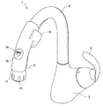
先ず、図1により、本発明の一実施形態による自動水栓の外観構成について説明する。図1は、本発明の自動水栓の一実施形態を斜め上方から見た斜視図である。
図1に示すように、本実施形態による自動水栓1は、台座2を有し、この台座2の上面の後方部からは、スパウト(吐水管)4が上方に延びると共に使用者の方に向けてR形状をなして延びている。このスパウト4は、台座2に対して所定の角度範囲で左右に回転可能となっている。このスパウト4の手前側、即ち、台座2の上面の前方部には、水量(湯量も含む。以下同様に含むものとする。)及び水温(湯温も含む。以下同様に含むものとする。)を調整するためのハンドル6が取りつけられている。このハンドル6は、左右に回転させて水温を調節すると共に上下に回動させて水量を調節するシングルレバーとして構成されている。
Embodiments of the present invention will be described below with reference to the accompanying drawings.
First, with reference to FIG. 1, an external configuration of an automatic faucet according to an embodiment of the present invention will be described. FIG. 1 is a perspective view of an embodiment of the automatic faucet according to the present invention as viewed obliquely from above.
As shown in FIG. 1, the
スパウト4の先端側には、ハンドシャワー8が取りつけられ、その先端部に、水或いは湯を吐出する吐水口10が形成されている。また、スパウト4の先端側には、人が手などをかざすと自動的に吐水するように人の手などを感知するための予洗いセンサー12と、予洗いセンサー12による人の手などの感知をオン又はオフに切り替える切替スイッチ14が設けられている。この切替スイッチ14は又、予洗いセンサー12により人の手などが感知された場合に自動で吐出し、或いは、感知されない場合に自動で止水する自動吐水モードをオン又はオフに切り替える役割も果たしている。さらに、切替スイッチ14のオン時に点灯し、オフ時に消灯するLED表示部16と、人が手などをかざすと連続して吐出するように人の手などを感知するための手かざしセンサー18と、が設けられている。これらの作動内容について詳しくは後述する。
A
次に、図2により、本発明の一実施形態による自動水栓の内部構成について説明する。図2は、本発明の一実施形態による自動水栓の内部構成を示すブロック図である。
図2に示すように、本実施形態による自動水栓1には、水を自動水栓1に供給する水管20及び湯を自動水栓1に供給する湯管22が接続されている。これらの管20、22は、止水栓部24に設けられた水管20用の止水栓25及び湯管22用の止水栓26で止水可能になっている。
止水栓部24を通った水又は湯は、それぞれ、水管20用の電磁弁30及び湯管22用の電磁弁32で開閉される。これらの開閉により、上述した吐水口10から水又は湯を吐出させるオン状態、或いは、水又は湯を吐出させないオフ状態を作り出すようになっている。
Next, the internal configuration of the automatic water faucet according to one embodiment of the present invention will be described with reference to FIG. FIG. 2 is a block diagram showing the internal configuration of the automatic faucet according to one embodiment of the present invention.
As shown in FIG. 2, a
Water or hot water that has passed through the
水及び湯は、それぞれ、電磁弁30、32を通過した後、給水ホース34及び給湯ホース36に導かれる。これらのホース34、36の先端部は、上述したハンドル6が設けられた部分に接続されている。このハンドル6の部分には、シングルカートリッジ38が取りつけられている。このシングルカートリッジ38により、ハンドル6の左右の回動量に応じて、給水ホース34からの水、及び、給湯ホース36からの湯が所定の割合で混合されて、所定の温度を有する水或いは湯が、ホース40に供給されるようになっている。ホース40は、接続継手42を介してシャワーホース44に接続されている。シャワーホース44の先端部は、上述したハンドシャワー8に取りつけられており、所定の温度を有する水或いは湯が、ハンドシャワー8の吐水口10から吐出されるようになっている。
Water and hot water are guided to the
ここで、上述した予洗いセンサー12、切替スイッチ14及び手かざしセンサー18の構成及び機能を説明する。
先ず、図2に示すように、予洗いセンサー12及び手かざしセンサー18は、それぞれ、防水コネクタ50を介して切替スイッチ14に接続され、この切替スイッチ14は、防水コネクタ52を介して、コントローラ54に接続されている。このコントローラ54は、予洗いセンサー12、切替スイッチ14及び手かざしセンサー18からのそれぞれの信号を検知して、その検知した信号の内容に基づいて、電磁弁30、32を開閉する。即ち、電磁弁30、32の開閉により、吐水口10からの水又は湯の吐出をオン又はオフにする。検知した信号の内容に基づいた具体的な制御内容は後述する。
Here, the configuration and functions of the above-described
First, as shown in FIG. 2, the
次に、ハンドシャワー8はスパウト4の下方側に設けられ、予洗いセンサー12は、その上方側に設けられている。予洗いセンサー12とは、斜め下方に向けた所定のセンサーエリアをセンシングして、人の手などを検知するものである。本実施形態では、この予洗いセンサー12が人の手などを検知している間、ハンドシャワー8から水又は湯が吐出されるようになっている。一方、予洗いセンサー12が人の手などを検知していなければ、ハンドシャワー8から水又は湯は吐出されないようになっている。このように、予洗いセンサー12によれば、センサーによるセンシングで、自動的に吐水するモード(自動吐水モード)とすることが出来る。
Next, the
ここで、この予洗いセンサー12は、切替スイッチ14により、その作動がオン又はオフされる。即ち、切替スイッチ14が一度押されたときには、オンとなり、上述したように予洗いセンサー12が人の手などを検知している間、ハンドシャワー8から水又は湯が吐出される。一方、切替スイッチ14が再度押されたときには、オフとなり、予洗いセンサー12が人の手などを検知していても、ハンドシャワー8から水又は湯が吐出されないようになっている。なお、切替スイッチ14を、単に、予洗いセンサー12によるセンシングのオンオフを切り替えるものとしても良い。
Here, the operation of the
LED表示部16は、切替スイッチ14により予洗いセンサー12の作動がオンとされているとき(予洗いセンサー12による人の手などの感知による吐水のオンオフが可能な状態)、点灯し、切替スイッチ14により予洗いセンサー12の作動がオフとされているとき(予洗いセンサー12による人の手などの感知による吐水のオンオフが不可能な状態)、消灯する。要は、予洗いセンサー12を使用するときに、使用者が切替スイッチ14を押せば、LED表示部16が点灯し、予洗いが可能であることを使用者が認識することが出来るのである。なお、「予洗い」とは、例えば、自動食器洗い機に食器などを入れる前に、ざっと洗うようなことを意味している。もちろん、自動食器洗い機に食器を入れるためでなく、人が食器を洗うことも可能である。
The
次に、手かざしセンサー18は、上方に湾曲したスパウト4の上部且つ右側に取りつけられており、斜め上方に向けた所定のセンサーエリアをセンシングして、人の手などを検知するものである。本実施形態では、この手かざしセンサー18が人の手などを、一度、検知すると、その後、連続して、ハンドシャワー8から水又は湯が吐出されるようになっている。そして、手かざしセンサー18が人の手などを、再度、検知すると、ハンドシャワー8からの水又は湯の吐出が停止されるようになっている。即ち、手かざしセンサー18は、人の手などを感知するたびに、ハンドシャワー8からの水又は湯の連続した吐出をオン、オフするようになっている。このように、手かざしセンサー18によれば、センサーによるセンシングで、連続的に吐水するモード(連続吐水モード)とすることが出来る。
Next, the hand-holding
次に、図3及び図4により、本発明の一実施形態による自動水栓の各センサーによる検知と、自動吐水モードのオンオフ及び電磁弁の開閉との関係を説明する。
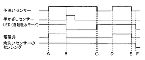
図3は、本発明の一実施形態による自動水栓の予洗いセンサー及び手かざしセンサーによる検知と電磁弁の開閉との関係を示すタイミングチャートであり、図4は、本発明の一実施形態による自動水栓の予洗いセンサー及び切替スイッチによる検知と電磁弁の開閉との関係を示すタイミングチャートである。
図3及び図4において、「予洗いセンサー」の示すタイミングチャートは、予洗いセンサー12のセンサーエリアに人の手などがある場合にオン、無い場合にオフを示し、「手かざしセンサー」の示すタイミングチャートは、手かざしセンサー18のセンサーエリアに人の手などがある場合にオン、無い場合にオフを示し、「切替スイッチ」の示すタイミングチャートは、切替スイッチ14が押された場合にオン、押されていない場合にオフを示し、「LED(自動吐水モード)」の示すタイミングチャートは、LED表示部16が点灯し自動吐水モードとなっている場合にオン、なっていない場合にオフを示し、「電磁弁」の示すタイミングチャートは、電磁弁30、32が開の場合にオン、閉の場合にオフを示し、「予洗いセンサーのセンシング」の示すタイミングチャートは、予洗いセンサー12によるセンシングが行われている場合にオン、行われていない場合にオフを示す。
Next, with reference to FIGS. 3 and 4, the relationship between detection by each sensor of the automatic faucet according to one embodiment of the present invention, on / off of the automatic water discharge mode, and opening / closing of the electromagnetic valve will be described.
FIG. 3 is a timing chart showing the relationship between detection by an automatic faucet pre-wash sensor and hand-holding sensor and opening / closing of a solenoid valve according to an embodiment of the present invention, and FIG. 4 according to an embodiment of the present invention. It is a timing chart which shows the relationship between the detection by the pre-wash sensor of an automatic faucet and a changeover switch, and opening and closing of a solenoid valve.
3 and 4, the timing chart indicated by the “pre-wash sensor” indicates ON when there is a human hand or the like in the sensor area of the
先ず、図3により、予洗いセンサー及び手かざしセンサーによる検知と、自動吐水モードのオンオフ及び電磁弁の開閉との関係について説明する。
図3に示すように、このタイミングチャートの始めには、LED表示部16が点灯しており、予洗いセンサー12が斜め下方に向けた所定のセンサーエリアをセンシングしている状態となっている。そして、図中Aの時点で、予洗いセンサー12が人の手などを感知して、予洗いセンサー12からコントローラ54に所定の出力がある。この出力を検知したコントローラ54は、その時点で電磁弁30、32を開く。その後、基本的には、予洗いセンサーが人の手などを感知している間、電磁弁30、32が開いた状態が続く。
次に、図中Bの時点では、手かざしセンサー18が人の手などを感知して、手かざしセンサー18からコントローラ54に所定の出力がある。この出力を検知したコントローラ54により、図3に示すように、予洗いセンサーエリア内に人の手などが存在していても(予洗いセンサー12から所定の出力があっても)、LED表示部16が消灯され、自動吐水モードがオフにされる。さらに、電磁弁30、32が閉じられて、止水する。
First, the relationship between the detection by the prewash sensor and the hand-holding sensor, the on / off of the automatic water discharge mode, and the opening / closing of the solenoid valve will be described with reference to FIG.
As shown in FIG. 3, at the beginning of this timing chart, the
Next, at time B in the figure, the hand-holding
ここで、本実施形態では、連続吐水モード用の手かざしセンサー18は、直接に手で押す型のものではなく、所定のセンサーエリアを有するものである。従って、自動水栓を使用している人が、意図せずに誤ってそのセンサーエリアに手などをかざしてしまう場合がある。即ち、連続吐水する意図がなくても、連続吐水モードとなってしまう可能性があるのである。そして、このように勝手にモードが切り替わって(自動吐水モードから連続吐水モードへの切り替わり)、使用者に不都合を与えることになる。即ち、使用者が予洗いを中止しようと思って予洗いセンサー12のセンサーエリアから手を離しても、連続吐水モードになっていると、無駄な吐水となってしまい、節水が図れなくなるのである。
Here, in this embodiment, the hand-holding
これに対し、本発明の一実施形態によれば、自動吐水モードにおいて吐水中に、連続吐水モード用の手かざしセンサー18が人の手などを感知すると、LED表示部16を消灯して自動吐水モードをオフにし、電磁弁30、32を閉じて、止水する。そして、手かざしセンサー18が人の手などを感知しても、この手かざしセンサー18に基づく連続吐水が行われない。従って、無駄な吐水が無く、節水が図れるようになる。
On the other hand, according to one embodiment of the present invention, when the hand-holding
そして、その後、如何にして自動吐水モードに復帰するかを説明する。図3に示すように、本実施形態では、上述したように、止水した場合であっても、予洗いセンサー12によるセンシング自体は継続される。そして、図中Cの時点で示すように、使用者が予洗いセンサー12のセンサーエリアから手を離すと、所定の出力が予洗いセンサー12からコントローラ54に送られ、この出力を検知したコントローラ54は、LED表示部16を点灯させて自動吐水モードをオンにする。従って、図中Dの時点で示すように、次に、使用者が予洗いセンサー12のセンサーエリアに手を入れると、所定の出力が予洗いセンサー12からコントローラ54に送られ、この出力を検知したコントローラ54は、電磁弁30、32を開き、吐水させる。このように、一度、自動吐水モードがオフにされても、再び予洗いセンサー12による自動吐水が可能となる。このような自動吐水モードへの復帰は、自動水栓1の使用者にとって使い勝手が良いものである。
After that, how to return to the automatic water discharge mode will be described. As shown in FIG. 3, in the present embodiment, as described above, sensing itself by the
そして、図中Eの時点で示すように、使用者が予洗いセンサー12のセンサーエリアから手を離すと、予洗いセンサー12からコントローラ54に送られた出力が無くなり、コントローラ54は、電磁弁30、32を閉じる。そして、止水される。さらに図中Fの時点で示すように、タイミングチャートとしては図3に示していないが、切替スイッチ14が押されて、LED表示部16が消灯して自動吐水モードがオフになる。
Then, as shown at time E in the figure, when the user releases his / her hand from the sensor area of the
先ず、図4により、予洗いセンサー及び切替スイッチによる検知と、自動吐水モードのオンオフ及び電磁弁の開閉との関係について説明する。
図4に示すように、このタイミングチャートの始めには、LED表示部16が点灯しており、予洗いセンサー12が斜め下方に向けた所定のセンサーエリアをセンシングしている状態となっている。そして、図中Gの時点で、予洗いセンサー12が人の手などを感知して、予洗いセンサー12からコントローラ54に所定の出力がある。この出力を検知したコントローラ54は、その時点で電磁弁30、32を開く。その後、基本的には、予洗いセンサーが人の手などを感知している間、電磁弁30、32が開いた状態が続く。
次に、図中Hの時点では、切替スイッチ14が押され、切替スイッチ14からコントローラ54に所定の出力がある。この出力を検知したコントローラ54により、図4に示すように、予洗いセンサーエリア内に人の手などが存在していても(予洗いセンサー12から所定の出力があっても)、LED表示部16が消灯され、自動吐水モードがオフにされる。さらに、電磁弁30、32が閉じられて、止水する。さらに、予洗いセンサー12のセンシング自体も停止される。そして、図中Iの時点に至るまで、予洗いセンサー12が人の手などを感知していても、自動吐水モードもオフにされ、予洗いセンサー12のセンシングも行われていないので、吐水されない。
First, the relationship between the detection by the prewash sensor and the changeover switch, the on / off of the automatic water discharge mode, and the opening / closing of the solenoid valve will be described with reference to FIG.
As shown in FIG. 4, at the beginning of this timing chart, the
Next, at the time of H in the figure, the
ここで、本実施形態では、自動吐水モードのオンオフの切替スイッチ14は、手で直接押すスイッチとして設けられている。従って、このスイッチ14が押された場合には、自動水栓を使用している人が、意図して押した、と考えるのが妥当である。従って、本発明の一実施形態によれば、自動吐水モードにおいて吐水中に、切替スイッチ14が押されると、LED表示部16を消灯して自動吐水モードをオフにし、電磁弁30、32を閉じて、止水する。さらに、予洗いセンサー12のセンシング自体を停止する。このようにして、無駄な吐水が無く、節水が図れるようになる。
Here, in this embodiment, the ON /
1 自動水栓
10 吐水口
12 予洗いセンサー
14 自動吐水モードの切替スイッチ
16 LED表示部
18 手かざしセンサー
30、32 電磁弁
54 コントローラ
DESCRIPTION OF
Claims (3)
吐水口付近の所定のセンサーエリアをセンシングし、そのセンサーエリアに差し出された人の手等を感知している間第1出力を発生し続ける自動吐水用の第1感知部と、
この第1感知部とは異なるセンサーエリアをセンシングし、そのセンサーエリアに差し出された人の手等を感知するたびに第2出力を発生する連続吐水用の第2感知部と、
上記第1感知部からの第1出力を検知している間は上記弁装置を開にして吐水させ、上記第1感知部からの第1出力を検知していない間は上記弁装置を閉にして吐水を停止する自動吐水モードと、上記第2感知部からの第2出力を検知すると上記弁装置を開にし、次の第2感知部からの第2出力があるまで上記弁装置を継続して開にする連続吐水モードと、を生じさせる第1制御手段と、
上記自動吐水モードをオン又はオフに切り替える切替出力を発生する切替手段と、
上記自動吐水モードがオンであり且つ上記第1感知部からの第1出力を検知している間で上記弁装置が開となり吐水している状態において、上記第2感知部からの上記第2出力を検知すると、上記弁装置を閉弁すると共に上記自動吐水モードをオフにする第2制御手段と、を有することを特徴とする自動水栓。 A valve device provided in the water discharge path to the water outlet;
A first sensor for automatic water discharge that senses a predetermined sensor area in the vicinity of the spout and continuously generates a first output while sensing a hand or the like of the person that has been pushed to the sensor area;
A second sensing unit for continuous water discharge that senses a sensor area different from the first sensing unit and generates a second output each time a person's hand or the like that is presented to the sensor area is sensed;
While the first output from the first sensing unit is detected, the valve device is opened to discharge water, and while the first output from the first sensing unit is not detected, the valve device is closed. When the automatic water discharge mode for stopping water discharge and the second output from the second sensing unit are detected, the valve device is opened, and the valve device is continued until there is a second output from the next second sensing unit. A continuous water discharge mode for opening the first control means,
Switching means for generating a switching output for switching the automatic water discharge mode on or off;
While the automatic water discharge mode is on and the valve device is open and water is discharged while the first output from the first sensor is detected, the second output from the second sensor. And a second control means for closing the valve device and turning off the automatic water discharge mode when the valve device is detected.
Priority Applications (1)
| Application Number | Priority Date | Filing Date | Title |
|---|---|---|---|
| JP2007278911A JP5077818B2 (en) | 2007-10-26 | 2007-10-26 | Automatic faucet |
Applications Claiming Priority (1)
| Application Number | Priority Date | Filing Date | Title |
|---|---|---|---|
| JP2007278911A JP5077818B2 (en) | 2007-10-26 | 2007-10-26 | Automatic faucet |
Publications (3)
| Publication Number | Publication Date |
|---|---|
| JP2009108489A JP2009108489A (en) | 2009-05-21 |
| JP2009108489A5 JP2009108489A5 (en) | 2010-11-25 |
| JP5077818B2 true JP5077818B2 (en) | 2012-11-21 |
Family
ID=40777262
Family Applications (1)
| Application Number | Title | Priority Date | Filing Date |
|---|---|---|---|
| JP2007278911A Active JP5077818B2 (en) | 2007-10-26 | 2007-10-26 | Automatic faucet |
Country Status (1)
| Country | Link |
|---|---|
| JP (1) | JP5077818B2 (en) |
Families Citing this family (1)
| Publication number | Priority date | Publication date | Assignee | Title |
|---|---|---|---|---|
| JP5077819B2 (en) * | 2007-10-26 | 2012-11-21 | Toto株式会社 | Automatic faucet |
Family Cites Families (4)
| Publication number | Priority date | Publication date | Assignee | Title |
|---|---|---|---|---|
| JPH0637247Y2 (en) * | 1989-12-29 | 1994-09-28 | 龍玉精工株式会社 | Automatic faucet system |
| JP3189957B2 (en) * | 1990-07-20 | 2001-07-16 | 東陶機器株式会社 | Automatic faucet |
| JP2007270538A (en) * | 2006-03-31 | 2007-10-18 | Toto Ltd | Automatic faucet |
| JP5077819B2 (en) * | 2007-10-26 | 2012-11-21 | Toto株式会社 | Automatic faucet |
-
2007
- 2007-10-26 JP JP2007278911A patent/JP5077818B2/en active Active
Also Published As
| Publication number | Publication date |
|---|---|
| JP2009108489A (en) | 2009-05-21 |
Similar Documents
| Publication | Publication Date | Title |
|---|---|---|
| US7690395B2 (en) | Multi-mode hands free automatic faucet | |
| JP5077819B2 (en) | Automatic faucet | |
| KR101301299B1 (en) | Control method to open and close water supply valve for the tap and foot sensor switch device using the same | |
| US11619318B2 (en) | Switch, induction control box comprising the same, and induction faucet | |
| JP5077818B2 (en) | Automatic faucet | |
| JP2007138574A (en) | Automatic faucet | |
| JP6348705B2 (en) | Automatic faucet | |
| JP2003301498A (en) | Toilet seat with warm-water washing device | |
| JP5908690B2 (en) | Faucet device | |
| JP4313613B2 (en) | Faucet device | |
| JP2012067537A (en) | Automatic water faucet | |
| JP4708928B2 (en) | Automatic faucet | |
| JP4313617B2 (en) | Faucet device | |
| JP2007291608A (en) | (automatic) faucet device | |
| JP2011179292A (en) | Faucet device | |
| JP6433820B2 (en) | Automatic faucet | |
| JP2007315042A (en) | Automatic faucet device | |
| JP2019019650A (en) | Water discharge device | |
| JP6382748B2 (en) | Automatic faucet | |
| JPH10306483A (en) | Automatic faucet | |
| JP2012136868A (en) | Automatic faucet device and faucet control method | |
| JP4652963B2 (en) | Automatic faucet | |
| JP4417650B2 (en) | Mixing faucet device | |
| JP4310801B2 (en) | Automatic faucet device | |
| JP2012021352A (en) | Automatic faucet |
Legal Events
| Date | Code | Title | Description |
|---|---|---|---|
| A521 | Written amendment |
Free format text: JAPANESE INTERMEDIATE CODE: A523 Effective date: 20101008 |
|
| A621 | Written request for application examination |
Free format text: JAPANESE INTERMEDIATE CODE: A621 Effective date: 20101008 |
|
| A977 | Report on retrieval |
Free format text: JAPANESE INTERMEDIATE CODE: A971007 Effective date: 20120802 |
|
| TRDD | Decision of grant or rejection written | ||
| A01 | Written decision to grant a patent or to grant a registration (utility model) |
Free format text: JAPANESE INTERMEDIATE CODE: A01 Effective date: 20120806 |
|
| A01 | Written decision to grant a patent or to grant a registration (utility model) |
Free format text: JAPANESE INTERMEDIATE CODE: A01 |
|
| FPAY | Renewal fee payment (event date is renewal date of database) |
Free format text: PAYMENT UNTIL: 20150907 Year of fee payment: 3 |
|
| R150 | Certificate of patent or registration of utility model |
Ref document number: 5077818 Country of ref document: JP Free format text: JAPANESE INTERMEDIATE CODE: R150 Free format text: JAPANESE INTERMEDIATE CODE: R150 |
|
| A61 | First payment of annual fees (during grant procedure) |
Free format text: JAPANESE INTERMEDIATE CODE: A61 Effective date: 20120819 |