JP5076645B2 - Label design creation device - Google Patents
Label design creation device Download PDFInfo
- Publication number
- JP5076645B2 JP5076645B2 JP2007139483A JP2007139483A JP5076645B2 JP 5076645 B2 JP5076645 B2 JP 5076645B2 JP 2007139483 A JP2007139483 A JP 2007139483A JP 2007139483 A JP2007139483 A JP 2007139483A JP 5076645 B2 JP5076645 B2 JP 5076645B2
- Authority
- JP
- Japan
- Prior art keywords
- label
- design
- label design
- image
- labels
- Prior art date
- Legal status (The legal status is an assumption and is not a legal conclusion. Google has not performed a legal analysis and makes no representation as to the accuracy of the status listed.)
- Active
Links
- 238000013461 design Methods 0.000 title claims description 336
- 238000003860 storage Methods 0.000 claims description 43
- 238000003384 imaging method Methods 0.000 claims 1
- 238000000034 method Methods 0.000 description 62
- 230000006870 function Effects 0.000 description 46
- 238000012545 processing Methods 0.000 description 34
- 239000000470 constituent Substances 0.000 description 28
- 230000008569 process Effects 0.000 description 28
- 239000004973 liquid crystal related substance Substances 0.000 description 23
- 238000010586 diagram Methods 0.000 description 13
- 238000005520 cutting process Methods 0.000 description 12
- 238000001514 detection method Methods 0.000 description 11
- 230000000694 effects Effects 0.000 description 6
- 230000004044 response Effects 0.000 description 6
- 238000007599 discharging Methods 0.000 description 4
- 230000010365 information processing Effects 0.000 description 4
- 238000004519 manufacturing process Methods 0.000 description 4
- 230000008859 change Effects 0.000 description 3
- XEEYBQQBJWHFJM-UHFFFAOYSA-N Iron Chemical compound [Fe] XEEYBQQBJWHFJM-UHFFFAOYSA-N 0.000 description 2
- 208000025174 PANDAS Diseases 0.000 description 2
- 208000021155 Paediatric autoimmune neuropsychiatric disorders associated with streptococcal infection Diseases 0.000 description 2
- 240000004718 Panda Species 0.000 description 2
- 235000016496 Panda oleosa Nutrition 0.000 description 2
- 230000015572 biosynthetic process Effects 0.000 description 2
- 238000005516 engineering process Methods 0.000 description 2
- 238000012905 input function Methods 0.000 description 2
- 230000007246 mechanism Effects 0.000 description 2
- 230000003936 working memory Effects 0.000 description 2
- 241000282816 Giraffa camelopardalis Species 0.000 description 1
- 241001465754 Metazoa Species 0.000 description 1
- 241000270295 Serpentes Species 0.000 description 1
- 230000004308 accommodation Effects 0.000 description 1
- 238000006243 chemical reaction Methods 0.000 description 1
- 238000012790 confirmation Methods 0.000 description 1
- 230000003247 decreasing effect Effects 0.000 description 1
- 229910052742 iron Inorganic materials 0.000 description 1
- 230000015654 memory Effects 0.000 description 1
- 238000004321 preservation Methods 0.000 description 1
- 238000010187 selection method Methods 0.000 description 1
- 238000012546 transfer Methods 0.000 description 1
- 239000002699 waste material Substances 0.000 description 1
Images


Classifications
-
- G—PHYSICS
- G06—COMPUTING; CALCULATING OR COUNTING
- G06T—IMAGE DATA PROCESSING OR GENERATION, IN GENERAL
- G06T11/00—2D [Two Dimensional] image generation
- G06T11/60—Editing figures and text; Combining figures or text
Landscapes
- Physics & Mathematics (AREA)
- General Physics & Mathematics (AREA)
- Engineering & Computer Science (AREA)
- Theoretical Computer Science (AREA)
- Record Information Processing For Printing (AREA)
- Printers Characterized By Their Purpose (AREA)
- Making Paper Articles (AREA)
Description
本発明は、ラベルデザイン作成装置に関し、例えば、複数の矩形形状のテープを組み合わせて、ある形状のラベルデザインを作成するラベルデザイン作成装置に適用し得る。 The present invention relates to a label design creation device, and can be applied to, for example, a label design creation device that creates a label design of a certain shape by combining a plurality of rectangular tapes.
例えば、店舗のウィンドウディスプレイの表示や施設内等での案内表示として、文字や記号や図形をカッティングしたデザインシールを用いることが広くなされている。また例えばファイル等の自分の持ち物にデザインシールを貼ることがよくなされている。 For example, a design sticker in which characters, symbols, and figures are cut is widely used as a display on a store window display or a guidance display in a facility. Also, for example, a design sticker is often put on one's belongings such as a file.
この種のデザインシールを利用する場合には、例えば非特許文献1に記載のカッティングマシンを使って所望のデザインシールを作成して用いたり、また例えば文房具店等で出来上がったデザインシールを購入して用いたりするのが一般的である。
When using this type of design sticker, for example, use a cutting machine described in Non-Patent
しかし、従来のカッティングマシンは大掛かりでありまた高価であるため、カッティングマシンを安易に購入できず、シールを作成することは難しい。そのため、ある程度見栄えのよいデザイン表示を簡単かつ手軽に作成することが望まれている。 However, since the conventional cutting machine is large and expensive, the cutting machine cannot be easily purchased and it is difficult to create a seal. Therefore, it is desired to easily and easily create a design display that looks good to some extent.
ところで、従来、矩形形状のテープに文字や記号や図形を印刷したラベルを作成するラベル作成装置がある。ラベル作成装置は、簡単かつ手軽にラベルを作成することができることから、オフィスや一般家庭等に広く普及している。 By the way, conventionally, there is a label creating apparatus that creates a label in which characters, symbols, and figures are printed on a rectangular tape. Since the label producing apparatus can easily and easily produce a label, it is widely used in offices and general households.
従来、ラベル作成装置が作成するラベルは、幅方向の長さが一定のラベルに限られている。セッティングしたテープよりも幅方向の長さが大きいラベルを作成する技術として、特許文献1に記載の拡大印刷技術があるが、矩形形状のテープを使用しているので、組み合わせたラベル形状自体にデザイン性はない。
上述のように、ある程度見栄えのよいデザイン表示を簡単かつ手軽に作成することが望まれている。 As described above, it is desired to easily and easily create a design display that looks good to some extent.
従来のラベル作成装置は、矩形形状のテープを使用してラベルを作成するため、作成されたラベルも矩形形状となってしまう。従来、ラベルの角をカッティングして、ラベル形状に丸みをつける加工技術はあるが、この場合でも、ラベル形状のデザイン性に限界がある。 Since the conventional label producing apparatus creates a label using a rectangular tape, the produced label also has a rectangular shape. Conventionally, there is a processing technique for rounding the label shape by cutting the corners of the label, but even in this case, there is a limit to the design of the label shape.
そのため、複数の矩形形状からなるラベルを組み合わせて、特定のラベルデザインを形成するためのラベルを作成するラベルデザイン作成装置が求められている。 Therefore, there is a need for a label design creation device that creates a label for forming a specific label design by combining a plurality of labels having a rectangular shape.
かかる課題を解決するために、第1の発明のラベルデザイン作成装置は、複数のラベルを組み合わせてあるデザインの形状を形成する、ラベルデザインが複数記憶された第1の記憶手段と、各ラベルデザインを形成する複数のラベルの組み合わせを表現したラベル組み合わせ情報が記憶された第2の記憶手段と、第1の記憶手段に記憶された複数のデザインの内、少なくとも1個のラベルデザインの選択を取り込む選択手段と、選択手段が取り込んだ選択されたラベルデザインに対応するラベル組み合わせ情報を第2の記憶手段から読み出す読み出し手段と、読み出し手段により読み出されたラベル組み合わせ情報に従い、ラベルデザインを構成する各ラベルを出力する出力手段とを備え、ラベル組み合わせ情報によって規定されるラベルが貼り合わされて形成されるラベルデザインの領域内に、1又は複数の画像を形成する領域を設定する画像形成領域設定手段と、領域に形成する画像を決定する画像作成手段と、画像作成手段で決定された画像を、画像形成領域設定手段で設定された領域内に画像形成する画像形成手段とを備えることを特徴とするものである。 In order to solve such a problem, a label design creation device according to a first aspect of the present invention includes a first storage unit that stores a plurality of label designs, and forms each design shape by combining a plurality of labels, and each label design. capturing a second storage means for combining label combination information representing a plurality of labels is stored to form, among the plurality of design that has been stored in the first storage means, the selection of at least one label design Each of the selection means, the reading means for reading the label combination information corresponding to the selected label design fetched by the selection means from the second storage means, and each label constituting the label design according to the label combination information read by the reading means and output means for outputting a label, the label defined by label combination information Determined by an image forming area setting means for setting an area for forming one or a plurality of images, an image creating means for determining an image to be formed in the area, and an image creating means the image, is characterized in Rukoto and an image forming means for forming an image on the image forming area setting set within the area unit.
ここで、第1の記憶手段と第2の記憶手段とは、物理的に異なる記憶手段である必要はなく、同一の記憶手段の場合も含む概念である。 Here, the first storage unit and the second storage unit do not need to be physically different storage units, but are a concept including the same storage unit.
第2の発明のラベルデザイン作成装置は、第1の発明のいずれかに記載のラベルデザイン作成装置において、さらに、画像形成領域設定手段により設定された領域内に画像を形成する画像を取り込む画像入力手段を備え、画像形成手段が、画像入力手段により取得された画像を、画像形成領域設定手段で設定された領域に画像形成するものである。 The label design creation device according to a second aspect of the present invention is the label design creation device according to any one of the first aspects, further comprising an image input for capturing an image for forming an image in an area set by the image formation area setting means And an image forming unit forms an image obtained by the image input unit in an area set by the image forming area setting unit .
第3の発明のラベルデザイン作成装置は、第1又は2の発明に記載のラベルデザイン作成装置において、さらに、各ラベルの貼り合わせ方を記したガイドを画面表示する表示手段と、各ラベルの貼り合わせ方を記したガイドを、ラベルデザインを構成するラベルとは別のラベルに画像形成して出力するガイド出力手段とを備えるものである。 Label design producing apparatus of the third invention, according to inventions of the first or in the label design creation device, further comprising display means for guiding the screen display that describes the bonding way of each label, for each label A guide output means for forming an image of a guide describing how to paste the images on a label different from the label constituting the label design and outputting the image is provided.
第4の発明のラベルデザイン作成装置は、第1〜3の発明のいずれかに記載のラベルデザイン作成装置において、さらに、一のラベル上に重畳して他のラベルが貼り合わされるラベルデザインにおいて、一のラベル上に、他のラベルが貼り合わされる位置の案内を画像形成する案内画像形成手段を備え、案内画像形成手段が、他のラベルに、当該ラベルを識別するための記号を画像形成するとともに、一のラベルにおける他のラベルが貼り合わされる位置に記号を画像形成するものである。
The label design creation device according to a fourth aspect of the present invention is the label design creation device according to any one of the first to third aspects of the invention , and further in a label design in which another label is superimposed on one label, Guide image forming means for forming an image of the position where another label is pasted on one label is provided, and the guide image forming means images a symbol for identifying the label on the other label. At the same time, a symbol is imaged at a position where another label of one label is pasted.
本発明のラベルデザイン作成装置によれば、複数の矩形形状からなるラベルを組み合わせた特定のラベルデザインを形成するためのラベルを作成することができる。 According to the label design creation device of the present invention, it is possible to create a label for forming a specific label design by combining a plurality of rectangular labels.
(A)第1の実施形態
以下では、本発明のラベルデザイン作成装置の第1の実施形態を、図面を参照しながら詳細に説明する。
(A) 1st Embodiment Below, 1st Embodiment of the label design production apparatus of this invention is described in detail, referring drawings.
第1の実施形態では、専用のラベルデザイン作成装置(ラベル作成装置)に本発明を適用した場合を想定して説明する。 In the first embodiment, description will be made assuming that the present invention is applied to a dedicated label design creation device (label creation device).
勿論、後述するように、本発明はCPUが処理プログラムを実行することで所定処理を実現させるソフトウェア処理を想定するものであるため、パーソナルコンピュータに接続するラベル作成装置やスタンドアロン型ラベル作成装置に本発明を適用することもできる。 Of course, as will be described later, since the present invention assumes a software process in which a CPU executes a processing program to realize a predetermined process, the present invention is applied to a label creating apparatus connected to a personal computer or a stand-alone type label creating apparatus. The invention can also be applied.
ここで、ラベルデザインとは、複数の矩形形状のラベルを組み合わせることで作り上げることができる特定の形状を有するものであり、必要に応じて、文字、記号、図形若しくはこれらの組み合わせたもの等が印刷されたものである。また、このラベルデザインを構成する各ラベルのことを構成ラベルという。ラベルデザイン作成装置は、ラベルデザインを構成する各構成ラベルを作成して排出する。また、構成ラベルには、文字、記号、図形、背景模様が印刷されているものだけでなく、これらが印刷されていないものも含む概念である。さらに、構成ラベルは、有色テープ、無色テープ、透明テープ等を適用することができ、またマグネットテープ、アイロンラベル等にも適用できるものである。 Here, the label design has a specific shape that can be created by combining a plurality of rectangular labels, and if necessary, characters, symbols, figures, or combinations thereof are printed. It has been done. Each label constituting this label design is referred to as a component label. The label design creation device creates and discharges each constituent label constituting the label design. In addition, the configuration label is a concept that includes not only characters, symbols, figures, and background patterns printed but also those that are not printed. Furthermore, as the configuration label, a colored tape, a colorless tape, a transparent tape, or the like can be applied, and a magnetic tape, an iron label, or the like can be applied.
(A−1)第1の実施形態の構成
図1は、第1の実施形態のラベルデザイン作成装置の電気的な構成を示すブロック図である。図2は、第1の実施形態のラベルデザイン作成装置の外観イメージを示す概略斜視図である。
(A-1) Configuration of First Embodiment FIG. 1 is a block diagram showing an electrical configuration of a label design creation device of the first embodiment. FIG. 2 is a schematic perspective view showing an appearance image of the label design creating apparatus of the first embodiment.
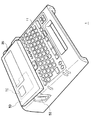
図2において、第1の実施形態のラベルデザイン作成装置1は、操作パネルとして文字や記号等のキーや機能キーや制御キー等を有するキー入力部11、入力された文字や記号等を表示したり又はラベルの出来上がりイメージを表示したりする液晶ディスプレイ35、ラベルデザインを構成する構成テープ(文字や記号や図形等が印刷されたテープも含む)を排出する排出口52、を少なくとも有して構成される。
In FIG. 2, the label
また、図2において、ラベルデザイン作成装置1は、装置筐体の内部にテープカートリッジTCを収容することができ、テープカートリッジTCの収容空間を覆う蓋体50を備える。液晶ディスプレイ35は、この蓋体50上に設けられている。
In FIG. 2, the label
図1において、第1の実施形態ラベルデザイン作成装置1は、大別して、入力部10、制御部20、出力部30を有して構成される。
In FIG. 1, the label
入力部10は、キー入力部11やテープ種類検出センサ12を備えるものである。
The input unit 10 includes a
キー入力部11は、上述した各種キーを備え、利用者により押下されたキーのキー信号(例えば文字コードデータや制御データ等)を、制御部20の入力インターフェース25に与えるものである。なお、第1の実施形態では、キー入力部11は、機構的なキーを想定しているが、タッチパネル等のように画面上で操作する押下するものとしてもよい。
The
テープ種類検出センサ12は、装填されているテープカートリッジTCのテープ幅長や色(透明を含む)等のテープ種類情報を検出し、そのテープ種類情報を制御部20に与えるものである。テープ種類情報の検出方法としては、例えば、予めテープカートリッジTCにはテープ幅長や色などを規定する孔などで構成された物理的な識別要素が設けられており、テープ種類検出センサ12はこの物理的な識別要素を読み取ってテープ種類情報を検出する。
The tape
出力部30は、印刷構成と表示構成とからなるものである。ここで、印刷構成は、テープに対して印刷を行なう構成であり、表示構成は、テープに印刷する入力情報や、操作ガイダンスのメッセージ等を表示するものである。 The output unit 30 includes a printing configuration and a display configuration. Here, the print configuration is a configuration for printing on a tape, and the display configuration is for displaying input information to be printed on the tape, a message for operation guidance, and the like.
ここで、印刷構成として、サーマルヘッド32は、例えば、固定的に設けられており、走行するテープに対して熱転写によって印刷を行なうものである。また、テープ・リボン走行機構31は、例えばステッピングテープや直流モータ等を中心として構成されるものであり、装填されている図示しないテープやインクリボンを所定の印刷位置や装置外部まで送り出すものである。これらサーマルヘッド32及びテープ・リボン走行機構31はそれぞれ、制御部20の制御下で、ヘッド駆動回路34や走行駆動回路(モータ等を含む)33によって駆動される。
Here, as a printing configuration, the
また、印刷されたテープの切断は、制御部20の制御下で、カッタ駆動回路(モータ等を含む)38によって駆動されるカッタ37によって行なわれる。切断用のカッタ37は、制御部20の制御の下、全切断モードにおいては表紙と裏紙とを共に切断するフルカッタ37aと、ハーフ切断モードにおいては裏紙を切断することなく表紙だけを切断するハーフカッタ37bとで構成される。
The printed tape is cut by a
次に、表示構成として、例えば所定サイズの文字を数行(例えば4行)に亘って数文字(例えば12文字)程度表示できる程度の液晶ディスプレイ35が設けられており、この液晶ディスプレイ35は、制御部20の制御下でディスプレイ駆動回路36によって駆動される。また、液晶ディスプレイ35は、入力文字列や行番号や印刷イメージや長さ情報等を表示するドット表示部2や属性インジケータ部3(3−1〜3−n)からなるので、ディスプレイ駆動回路36も、大別すると、ドット表示部2に対応した駆動部36a、及び属性インジケータ部3に対応した駆動部36bからなる。
Next, as a display configuration, for example, a
制御部20は、例えば、マイクロコンピュータによって構成されており、CPU21、ROM22、RAM23、キャラクタジェネレータROM(CG−ROM)24、入力インターフェース25、及び出力インターフェース26がシステムバス27を介して接続されている。
The control unit 20 includes, for example, a microcomputer, and a
ROM22は、1又は複数のROMチップでなり、各種の処理プログラムや、かな漢字変換用辞書データ等の固定データが格納されている。また、第1の実施形態では、ROM22には、ラベルデザイン作成プログラム22a、ラベルデザイン設定フォーム保存部22bが格納されている。
The
このラベルデザイン作成プログラム22aは、複数のラベルを組み合わせることで、あるラベルデザインを作り上げることができるよう、当該ラベルデザインを構成する複数の構成ラベルを作成するプログラムである。
The label
図3は、ラベルデザイン作成プログラム22aの実行により実現される機能を説明する機能ブロック図である。
FIG. 3 is a functional block diagram illustrating functions realized by executing the label
図3に示すように、ラベルデザイン作成プログラム22aにより実現される機能としては、ラベルデザイン選択機能部41、ラベルデザイン作成機能部42、出力制御部43、を少なくとも有する。
As shown in FIG. 3, the functions realized by the label
ラベルデザイン選択機能部41は、ラベルデザイン作成処理の際、ラベルデザイン設定フォーム保存部22bに設定されているラベルデザインの種類を表示させ、利用者により選択されたラベルデザインの設定フォーマットを、ラベルデザイン設定フォーム保存部22bから取得するものである。
The label design
ラベルデザイン作成機能部42は、ラベルデザイン選択機能部41が取得した利用者の選択したラベルデザインの設定フォーマットに基づいて、ラベルデザインを形成するために必要な構成ラベルを作成するものである。
The label design
出力制御部43は、ラベルデザイン作成機能部42が作成した構成ラベルを出力する際に、所定の機能を実現するものである。
The
ラベルデザイン作成プログラム22aが実行されることにより、ラベルデザイン作成装置1は、ラベルデザインの構成する矩形形状のラベル(構成ラベル)を出力することができる。この構成ラベルを利用者が組み合わせることで、簡単かつ手軽に、所望のラベルデザインを作り上げることができる。
By executing the label
また、ラベルデザイン設定フォーム保存部22bは、予め設定された複数のラベルデザインの設定フォームが記憶されたものである。
The label design setting
図4は、ラベルデザイン設定フォーム保存部22bが記憶するラベルデザインの設定フォームの構成例を示すものである。図4に例示するように、ラベルデザイン設定フォーム保存部22bは、予め設定された複数のラベルデザインと、それらラベルデザインを構成するラベル組み合わせ情報とを保存している。これにより、利用者は、デザインを選択するだけで、ラベルデザインを形成できる。
FIG. 4 shows a configuration example of a label design setting form stored in the label design setting
図4において、ラベルデザイン設定フォーム保存部22bの設定フォームは、「ラベルデザイン」を項目として有する。また、ラベル組み合わせ情報として、「構成ラベル番号(No.)」、「テープ幅」、「テープ色」、「長さ」、「背景模様(地紋)」、「文字入力」を項目として有する。
In FIG. 4, the setting form of the label design setting
「ラベルデザイン」は、ラベルデザインを識別する「識別番号(No.)」及び「名称」の項目を有する。「構成ラベル番号(No.)」は、ラベルデザインを構成する各構成ラベルを識別する番号である。「テープ幅」は、構成ラベルのテープ幅方向の長さであり、「テープ色」は、構成ラベルのテープの色であり、「長さ」は、構成ラベルの長さ方向の長さである。 The “label design” includes items of “identification number (No.)” and “name” for identifying the label design. The “configuration label number (No.)” is a number for identifying each configuration label constituting the label design. “Tape width” is the length of the component label in the tape width direction, “Tape color” is the tape color of the component label, and “Length” is the length of the component label in the length direction. .
また、「背景模様(地紋)」は、テープに背景模様を印刷するか否かを項目であり、「文字入力」は、構成ラベルのうち、文字入力可能な構成ラベルであるか否かを示す項目である。なお、「背景模様」の項目には、別途設けられた背景模様の設定フォームのうち、背景模様として決定する識別番号が格納されるようにしてもよい。 In addition, “background pattern (background pattern)” is an item indicating whether or not a background pattern is printed on a tape, and “character input” indicates whether or not a component label is a component label capable of character input. It is an item. In the “background pattern” item, an identification number determined as a background pattern in a separately provided background pattern setting form may be stored.
背景模様としては、例えば、「きりん」のデザインの場合には、一定の大きさの黒丸を多数テープに印刷できるように、予め設定フォームに設定されている。これにより、矩形ラベルを出力する際に、設定フォームに設定されている情報に基づいて、例えば黒丸を多数自動印刷したラベルを出力することができる。 For example, in the case of a “Kirin” design, the background pattern is set in advance in a setting form so that a large number of black circles of a certain size can be printed on the tape. Thereby, when outputting a rectangular label, the label which printed many black circles automatically, for example based on the information set to the setting form can be output.
文字入力としては、利用者が入力した文字をラベルに印刷して出力できるようにする。このとき、文字入力するラベルを利用者が指定できる。また、複数枚のラベルにまたがって、入力文字を印刷できるようにしてもよい。 As character input, characters input by the user are printed on a label so that they can be output. At this time, the user can specify a label for inputting characters. Further, the input characters may be printed across a plurality of labels.
例えば、図4において、「矢印」の形状は、3枚の構成ラベルを組み合わせて形成することができるものである。そこで、図4に示すように、「長さ」が「5cm」、「3cm」、「3cm」の3枚の構成ラベルを作成できるように設定されている。なお、「矢印」の形状の「テープ幅」は「12mm」のテープを用いることがデフォルト設定されており、「テープ色」については、設定されておらず「‐」としている。また、「構成ラベルNo.1」の構成ラベルが文字入力可能なラベルである。そして、これら3枚の構成ラベルを組み合わせると、図5(A)に示すような「矢印」の形状を形成することができる。 For example, in FIG. 4, the shape of the “arrow” can be formed by combining three component labels. Therefore, as shown in FIG. 4, it is set so that three configuration labels having “length” of “5 cm”, “3 cm”, and “3 cm” can be created. Note that “tape width” in the shape of “arrow” is set by default to use a tape of “12 mm”, and “tape color” is not set and is set to “−”. Further, the configuration label “configuration label No. 1” is a label in which characters can be input. Then, when these three component labels are combined, the “arrow” shape as shown in FIG. 5A can be formed.
また例えば、図4において、「家」の形状は、「テープ幅」が「12mm」のテープについて、「長さ」が「2cm」、「6cm」、「8cm」、「4cm」、「4cm」の5枚の構成ラベルが作成できるように設定されている。なお、「家」の形状の「テープ色」は「赤色」のテープを用いることがデフォルト設定されているが、「テープ幅」については設定されていない。また、すべての構成ラベルが、文字入力可能なラベルである。そして、これら5枚の構成ラベルを組み合わせると、図5(B)に示すような「家」の形状を形成することができる。 Further, for example, in FIG. 4, the shape of “house” is “2 cm”, “6 cm”, “8 cm”, “4 cm”, “4 cm” for “tape width” of “12 mm” tape. The five configuration labels can be created. Note that the “tape color” of the “house” shape defaults to using a “red” tape, but “tape width” is not set. In addition, all component labels are labels on which characters can be input. When these five component labels are combined, a “house” shape as shown in FIG. 5B can be formed.
さらに例えば、図4において、「きりん」の形状は、「長さ」が、「2cm」、「6cm」、「6cm」、「1cm」の4枚の構成ラベルが作成できるように設定されている。なお、「きりん」の形状は、「テープ幅」が「18mm」の「黄色」のテープを用いることが要件として設定されている。また、すべての構成ラベルが背景模様が印刷されるラベルであり、「構成ラベルNo.2」及び「構成ラベルNo.3」が文字入力可能なラベルである。そして、これら4枚の構成ラベルを組み合わせると、図5(C)に示すような「きりん」の形状を形成することができる。 Further, for example, in FIG. 4, the shape of “Kirin” is set so that four configuration labels with “length” of “2 cm”, “6 cm”, “6 cm”, and “1 cm” can be created. . The shape of “Kirin” is set as a requirement to use a “yellow” tape whose “tape width” is “18 mm”. All the configuration labels are labels on which a background pattern is printed, and “configuration label No. 2” and “configuration label No. 3” are labels on which characters can be input. Then, by combining these four component labels, a “giraffe” shape as shown in FIG. 5C can be formed.
なお、図4は、ラベルデザイン設定フォーム保存部22bの設定フォームの例示であり、設定フォームは、図4に示していない項目を備えるようにしてもよい。例えば、構成ラベルの出来上がりイメージを示すイメージ形状の項目を備え、各ラベルデザインのイメージデータを格納するようにしてもよい。
FIG. 4 is an example of the setting form of the label design setting
また、図5(C)に示すように、文字入力される場合、文字が入力される構成ラベル(例えば「出口はこちらです」と付されたラベル)の長さを、入力される文字の数、大きさに応じて変化するようにしてもよい。これにより、例えば、入力文字が2文字の場合には、胴が短い「きりん」のデザインラベルが作れるようにし、入力文字が5文字の場合には、胴が長い「きりん」のデザインラベルが作れるようにすることができる。 In addition, as shown in FIG. 5C, when characters are input, the length of the constituent label (for example, a label attached with “Exit here”) is input as the number of input characters. It may be changed according to the size. Thus, for example, when the input character is 2 characters, a design label of “Kirin” with a short torso can be made, and when the input character is 5 characters, a design label of “Kirin” with a long torso can be made. Can be.
さらに、文字が入力される構成ラベルの長さが固定としてもよい。これにより、文字が入力できる領域が固定されるので、文字数が少ない場合には、文字サイズを大きくしたり、文字間隔を広くしたりすることができ、文字数が多い場合には、文字サイズを小さくしたり、文字間隔を狭くしたりすることができる。 Furthermore, the length of the component label into which characters are input may be fixed. As a result, the area where characters can be entered is fixed, so when the number of characters is small, the character size can be increased and the character spacing can be increased. When the number of characters is large, the character size is decreased. And the character spacing can be narrowed.
RAM23は、1又は複数のRAMチップでなり、ワーキングメモリとして用いられるものであり、また、利用者入力に係る固定データ等も格納するものである。図1では、RAM23として記載しているが、ワーキングメモリとして用いられる他のメモリ素子(例えばEEPROM等)も含む概念である。RAM23は、印刷する文字列をドット展開して格納する印刷バッファや、入力文字列等についての表示画像を格納する表示バッファや、印刷や入力に係る文字データ等を格納するテキストバッファや、行番号についての表示態様を保持する行番号状態保持バッファや、属性インジケータ3についての表示態様を保持する属性インジケータ状態保持バッファ等を有する。
The
CG−ROM24は、当該ラベルデザイン印刷装置1に用意されている文字や記号のドットパターンを格納しているものであり、文字や記号を特定するコードデータが与えられたときに対応するドットパターンを出力するものである。なお、表示用と印刷用とで別個のCG−ROMが設けられていてもよい。フォント情報の格納形式はアウトラインフォント形式及びビットマップ形式のいずれであってもよい。
The CG-
入力インターフェース25は、入力部10及び制御部20間のインターフェースを行なうものであり、出力インターフェース26は、出力部30及び制御部20間のインターフェースを行なうものである。
The
CPU21は、入力部10からの入力信号やそのときの処理段階に応じて定まるROM22内の処理プログラムを、RAM23をワーキングエリアとして利用しながら、また必要ならばROM22やRAM23に格納されている固定データを適宜用いて処理するものであり、その処理状況や処理結果等を液晶ディスプレイ35に表示させたりテープに印刷させたりするものである。
The
(A−2)第1の実施形態の動作
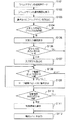
次に、第1の実施形態のラベルデザイン作成処理の動作を、図面を参照しながら詳細に説明する。図6は、第1の実施形態のラベルデザイン作成処理を説明する動作フローチャートである。
(A-2) Operation of the First Embodiment Next, the operation of the label design creation process of the first embodiment will be described in detail with reference to the drawings. FIG. 6 is an operation flowchart for explaining label design creation processing according to the first embodiment.
まず、ラベルデザインを作成しようとする利用者の操作を受けて、CPU21は、ラベルデザイン作成プログラム22aを実行するラベルデザイン作成処理モードになる(ステップS101)。
First, in response to a user's operation to create a label design, the
図7(A)は、液晶ディスプレイ35に表示させるメニュー画面の画面例を示す。ラベルデザイン作成処理モードにする方法としては、例えば、利用者が、液晶ディスプレイ35に表示されるメニュー画面を見ながら、キー入力部11を操作して、ラベルデザイン作成処理を実行する選択肢を選択する方法を適用することができる。このとき、利用者は、ラベルデザイン作成処理を実行する選択肢にカーソルを合わせて選択する方法や、選択肢番号を入力し実行キーを操作する方法等を適用できる。またラベルデザイン作成処理モードにする別の方法としては、例えば、ラベルデザイン作成処理の処理モードを起動させる専用キーを設け、利用者が、この専用キーを操作する方法を適用できる。
FIG. 7A shows a screen example of a menu screen displayed on the
CPU21がラベルデザイン作成処理モードになると、CPU21は、ラベルデザイン設定フォーム保存部22bに設定されているラベルデザインを選択させる選択画面を、液晶ディスプレイ35に表示させる(ステップS102)。
When the
図7(B)は、液晶ディスプレイ35に表示させるラベルデザインの選択画面の画面例を示す。このラベルデザインの選択画面は、ラベルデザイン設定フォーム保存部22bに設定されている全てのラベルデザインについて、「ラベルデザインの番号(No.)」及び「名称」を選択肢として表示させる。
FIG. 7B shows a screen example of a label design selection screen to be displayed on the
このとき、ラベルデザイン設定フォーム保存部22bにラベルデザインのイメージ形状が格納されている場合には、各ラベルデザインのイメージも併せて表示させるようにしてもよい。また、各ラベルデザインのイメージ形状だけを表示させるようにしてもよい。
At this time, when the image shape of the label design is stored in the label design setting
液晶ディスプレイ35上にラベルデザインの選択画面が表示させると、CPU21は、利用者により選択されたラベルデザインを取り込む(ステップS103)。
When the label design selection screen is displayed on the
CPU21は、利用者により選択されたラベルデザインについて、ラベルデザイン設定フォーム保存部22bを参照して、複数の構成ラベルのうち文字入力可能な構成ラベルを有するものであるか否かを判断する(ステップS104)。
The
選択されたラベルデザインが文字入力可能な構成ラベルを有するものである場合、CPU21は、液晶ディスプレイ35に文字入力画面を表示させる(ステップS105)。また、文字入力可能な構成ラベルがない場合には、ステップS108に移行する。
When the selected label design has a configuration label that allows character input, the
液晶ディスプレイ35に文字入力画面が表示されると、利用者は、キー入力部11を操作して、構成ラベルに印刷する文字、記号、図形等を入力する。このとき、複数の構成ラベルにまたがって文字、記号、図形等を印刷できるように、拡大文字の入力をすることができる。
When a character input screen is displayed on the
また、利用者が文字の入力を希望しない場合には、利用者は文字入力をせず、例えば画面表示上の「文字入力終り」等の選択肢を選択して文字入力処理を終了してもよい。 In addition, when the user does not wish to input characters, the user may not input characters, but may select an option such as “End of character input” on the screen display to end the character input process. .
利用者により文字が入力されると(ステップS106)、CPU21は、入力された文字を取り込む(ステップS107)。また、利用者による文字入力がない場合、CPU21は、文字入力処理を終了し、ステップS108に移行する。
When a character is input by the user (step S106), the
次に、CPU21は、テープ種類検出センサ12からテープ種類検出結果を受け取り、テープ種類検出結果に基づいて、現在装填されているテープの種類(テープ幅、テープ色)がラベルデザイン設定フォーム保存部22bに設定されている、対応するラベルデザイン形状の「テープ幅」、「テープ色」に一致しているか否かを判断する(ステップS108)。
Next, the
そして、現在装填されているテープ種類(テープ幅、テープ色)がラベルデザイン設定フォーム保存部22bに設定の「テープ幅」、「テープ色」に一致しない場合、CPU21は、設定されている「テープ幅」、「テープ色」のテープカートリッジTCが正しく装填されていない旨を、液晶ディスプレイ35に表示させる(ステップS109)。
If the currently loaded tape type (tape width, tape color) does not match the “tape width” and “tape color” set in the label design setting
このとき、CPU21は、ラベルデザイン設定フォーム保存部22bに設定されている「テープ幅」、「テープ色」を同時に表示するようにしてもよい。これにより、交換を要求するテープ種類を利用者に示すことができる。
At this time, the
利用者は、液晶ディスプレイ35の表示画面を見て、ラベルデザイン設定フォーム保存部22bに設定のテープカートリッジTCに交換すると、CPU21は、テープ種類検出センサ12からのテープ種類検出結果に基づいて、ラベルデザイン設定フォーム保存部22bに設定のテープ種類が装填されていることを判断し(ステップS108)、ステップS110に移行する。
When the user looks at the display screen of the
ここで、図6に示すラベルデザイン作成処理では、利用者が、正しいテープカートリッジTCを装填するまで、その後の処理に移行しないものとする。しかし、後述するように、ラベルデザイン設定フォーム保存部22bに設定されているラベルデザインの「テープ幅」、「テープ色」とは別に、利用者が指定したテープ種類で作成させる場合には、テープカートリッジTCを交換しなくても、その後の処理に移行させることできる。
Here, in the label design creation process shown in FIG. 6, it is assumed that the process does not proceed to the subsequent process until the user loads the correct tape cartridge TC. However, as will be described later, in addition to the “tape width” and “tape color” of the label design set in the label design setting
次に、CPU21は、ラベルデザイン設定フォーム保存部22bを参照して、利用者により選択されたラベルデザインについて背景模様が設定されているか否かを判断する(ステップS110)。
Next, the
そして、選択されたラベルデザインについて背景模様の設定がなされている場合、CPU21は、選択されたラベルデザインに対応する背景模様を選択させる(ステップS111)。
If a background pattern is set for the selected label design, the
ここで、背景模様の選択方法としては、種々の方法を適用することができるが、例えば、予め設定された複数の背景模様の設定フォームを保存しておき、選択されたラベルデザインに対応する背景模様を選び出すことで実現することができる。このとき、背景模様の設定フォームには、背景模様を印刷する領域情報が設定されている。例えば、「きりん」のラベルは多数の黒丸を自動印刷できるようするため、例えば、丸の大きさ、丸と丸との間隔等の情報が設定されている。 Here, various methods can be applied as the background pattern selection method. For example, a plurality of preset background pattern setting forms are stored and the background corresponding to the selected label design is stored. This can be achieved by selecting patterns. At this time, area information for printing the background pattern is set in the background pattern setting form. For example, in order to automatically print a large number of black circles on the “Kirin” label, for example, information such as the size of the circle and the interval between the circles is set.
また、選択されたラベルデザインについて背景模様の設定がない場合には、CPU21は、ステップS112に移行する。
If no background pattern is set for the selected label design, the
ステップS112では、CPU21が、ラベルデザイン設定フォーム保存部22bを参照して、それぞれ特定の長さにテープを切断させることで、利用者により選択されたラベルデザインを構成する各構成ラベルを作成させる。
In step S112, the
各構成ラベルの作成の際、入力文字や背景模様を印刷する必要のある構成ラベルについては、CPU21は、入力文字や背景模様をテープに印刷した後、所定長でテープを切断して、入力文字や背景模様が印刷された構成ラベルを作成させる。
When creating each constituent label, the
ここで、各構成ラベルの排出処理として、例えば、それぞれ作成した構成ラベルを、そのまま順次排出するようにしてもよい。 Here, as the discharging process of each component label, for example, the component labels created may be sequentially discharged as they are.
また、別の方法として、構成ラベルの排出の際に、各構成ラベルをどのように貼り合わせてラベルデザインを作り上げるかを示す組合せ方法を示すようにしてもよい。このように組合せ方法を示すことにより、その組合せ方法を見ながら利用者が組み合わせることができるので、極めて容易にラベルデザイン形状を形成することができ、貼り合わせミスを低減させることができる。 Further, as another method, a combination method indicating how the component labels are bonded to form a label design when the component labels are discharged may be shown. By showing the combination method in this way, the user can combine them while looking at the combination method. Therefore, it is possible to form a label design shape very easily and reduce bonding errors.
なお、以下で説明する図8、図11、図24に示す、「案内ラベル」及び「貼り合わせ位置」は、本発明の「案内」の概念に含まれるものである。また、図9で説明するように、表示手段にラベルの組み合わせ方法を表示することも、本発明の「案内」の概念に含まれるものである。 Note that “guide label” and “bonding position” shown in FIGS. 8, 11, and 24 described below are included in the concept of “guide” of the present invention. In addition, as described in FIG. 9, displaying the label combination method on the display means is also included in the concept of “guidance” of the present invention.
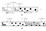
図8は、ラベルデザイン形状の組合せ方法の表示を示す例を説明する説明図である。 FIG. 8 is an explanatory diagram illustrating an example of displaying a label design shape combination method.
例えば、図8(A)に示すように、CPU21は、各構成ラベルを排出する際、ラベルデザインの完成イメージと、当該構成ラベルがどの部分のものであるかを示す案内ラベルをラベルの先頭に印刷させる。図8(A)では、斜線部分が当該構成ラベルの貼り合わせ位置としている。また、CPU21は、案内ラベル部分と構成ラベル本体部分との間をハーフカットで切断させる。また、CPU21は、各構成ラベル間についてはフルカットで切断させる。これにより、利用者に対し、構成ラベル本体と案内ラベルとの関係をわかり易く示すことができる。
For example, as shown in FIG. 8A, when discharging each component label, the
また例えば、図8(B)に示すように、CPU21は、ラベルデザインの完成イメージと、各ラベルに番号を付した案内ラベルをラベル先頭に印刷させる。案内ラベルに示す番号は、このラベル表示以後に排出される構成ラベルの並び順に相当するものである(また、構成ラベル番号に相当するものでもある)。また、CPU21は、案内ラベル部分と各構成ラベルとの間、及び、各構成ラベル間をハーフカットで切断させる。
Further, for example, as shown in FIG. 8B, the
なお、図8(A)に示す案内ラベルと図8(B)に示す案内ラベルとを組み合わせて出力してもよい。 In addition, you may output combining the guidance label shown to FIG. 8 (A), and the guidance label shown to FIG. 8 (B).
また、図24に示すように、例えば「H」と「O」等のように、2以上の分離したラベルデザインの構成ラベルを作成する際、それぞれのラベル群毎に次のようにして出力するようにしてもよい。例えば、「H」については、図8(B)と同じように、案内ラベルをラベル先頭に印刷して「H」の構成ラベル群を作成し、構成ラベル群の作成が終了すると、フルカットで切断する。このとき、「H」の複数の構成ラベル間はハーフカットとする。その後、次の「O」について、「H」と同様にして構成ラベル群を作成する。 Also, as shown in FIG. 24, when creating two or more separated label design component labels such as “H” and “O”, for example, the following is output for each label group: You may do it. For example, for “H”, as in FIG. 8B, a guide label is printed at the head of the label to create a component label group “H”. Disconnect. At this time, a half cut is made between a plurality of constituent labels of “H”. Thereafter, a configuration label group is created for the next “O” in the same manner as “H”.
さらに、CPU21は、液晶ディスプレイ35に組合せ方法を表示するようにしてもよい。図9は、液晶ディスプレイ35上に表示させるラベルデザインの組合せ方法の表示例を説明する説明図である。
Further, the
図9に示すように、CPU21は、ラベルデザインの完成イメージと、構成ラベルの組み合わせ順序を液晶ディスプレイ35に表示させる。例えば、図9(A)の表示画面を表示させた後に、図9(B)の表示画面に切り替えて表示させる。このように、ラベルデザインが完成するまで繰り返し表示切替させる。
As shown in FIG. 9, the
この場合、例えば、ラベルを組み合わせる順番を表示させるための組み合わせ順序情報を設定フォームに予め設定しておき、CPU12が、この設定フォームの組み合わせ順序情報に基づいて、ディスプレイ駆動回路36を制御することで、ラベルを組み合わせる方法を表示させることができる。
In this case, for example, combination order information for displaying the order of combining the labels is set in advance in the setting form, and the
なお、表示画面の切替方法としては、例えば、CPU12が、所定時間毎に画面を切り替え制御するようにしてもよいし、利用者によるキー入力部11の操作を受けて切り替え(選択)するようにしてもよいし、また、所定時間毎の自動切替と利用者操作による選択の両方を備えるようにしたりしてもよい。
As a display screen switching method, for example, the
また、図8(A)又は(B)に示す案内ラベルの印刷と共に、図9に示す液晶ディスプレイ35上で組合せ方法を表示させるようにしてもよい。
Moreover, you may make it display the combination method on the
さらにまた、CPU21は、構成ラベル同士を貼り合わせる位置を印刷させるようにしてもよい。
Furthermore, the
図10、図11及び図25は、構成ラベル同士の貼り合わせ位置の印刷例を示す図である。 10, 11, and 25 are diagrams illustrating a printing example of a bonding position between component labels.
例えば、図10では、「へび」形状の構成ラベルを示している。また、図10では、複数のラベルにまたがって文字が印刷される場合の例である。図10(A)は、ラベルデザインの出来上がりを示す。図10(A)に示すように、「テ」、「プ」、「ラ」も文字はそれぞれ上段と下段のラベルにまたがって印刷される。この場合、図10(B)に示すように、CPU21は、ラベル先頭に案内ラベルを印刷させると共に、各構成ラベルに対応する文字の一部分を印刷させる。また、図10(C)に示すように、CPU21は、各構成ラベルの貼り合わせ位置を示す指標(マーク)を印刷させる。このとき、構成ラベルのハーフカット代に貼り合わせ位置を示す指標(マーク)を付けたり、また構成ラベルを貼り合わせることで、この貼り合わせ位置を示す指標(マーク)を隠すことができるように印刷させたりしてもよい。これにより、貼り合わせたときに、貼り合わせ位置を示す指標(マーク)を隠すことができるので、出来上がりがきれいなラベルデザインを形成することができる。
For example, FIG. 10 shows a “snake” shaped configuration label. FIG. 10 shows an example in which characters are printed across a plurality of labels. FIG. 10A shows the completed label design. As shown in FIG. 10A, the characters “te”, “p”, and “la” are also printed across the upper and lower labels, respectively. In this case, as shown in FIG. 10B, the
例えば、図11(A)では、「きりん」形状の構成ラベルを示している。そのうち、「構成ラベルNo.2」のように、CPU21は、「構成ラベルNo.1」及び「構成ラベルNo.3」の貼り合わせ位置を示す指標(マーク)を印刷させる。また、「構成ラベルNo.3」のように、CPU21は、「構成ラベルNo.4」の貼り合わせ位置を示す指標(マーク)を印刷させる。これにより、構成ラベルの貼り合わせ位置を利用者にわかり易く示すことができるので、ラベルデザインの容易な形成が可能となる。
For example, FIG. 11A shows a “Kirin” -shaped configuration label. Among them, like “configuration label No. 2”, the
また例えば、図11(B)では、「矢印」形状の構成ラベルを示している。図11(B)に示すように、CPU21は、構成ラベル間を貼り合わせる部分(重ね合わせ部分)が分かるように、重ね合わせ部分を印刷させる。これにより、利用者が重ね合わせ部分に構成ラベルを貼り合わせることで、容易にラベルデザインを形成させることができる。
Further, for example, FIG. 11B shows a configuration label having an “arrow” shape. As shown in FIG. 11B, the
さらに、図11(C)では、「矢印」形状の構成ラベルを示している。図11(C)に示すように、CPU21は、構成ラベルの重ね合わせ部分に、重ね合わせる構成ラベルの番号を印刷させる。このように、番号を印刷することで、重ね合わせる構成ラベルを特定できるので、より簡単にラベルデザインを形成させることができる。
Further, FIG. 11C shows an “arrow” -shaped configuration label. As shown in FIG. 11C, the
また、図25(A)、(B)に示すように、構成ラベルの重複部分を網点で示すようにする。これにより、単色印刷しかできないラベル作成装置であっても、複数枚の重複部分を表現することができる。 In addition, as shown in FIGS. 25A and 25B, overlapping portions of the component labels are indicated by halftone dots. Thereby, even if it is a label production apparatus which can only perform monochromatic printing, a plurality of overlapping portions can be expressed.
上記では、構成ラベルの組合せ方法を表示する例を示したが、このほかに、CPU21は、構成ラベルに切り取り線を印刷するようにしてもよい。図12は、構成ラベルに切り取り線を印刷する場合の例を示す図である。
In the above, an example of displaying the combination method of the configuration labels has been shown. However, the
例えば、図12では、「戦車」形状の構成ラベルを示している。そのうち、「構成ラベルNo.2」のように、CPU21は、切り取り線を印刷する。その後、利用者が切り取り線に沿って切り離すことで、「構成ラベルNo.2」のラベルに丸みをつけることができる。すなわち、矩形形状のラベルを変形させることができるので、ラベルデザインにバリエーションを与えることができる。
For example, FIG. 12 shows a “tank” shaped configuration label. Among them, the
以上のようにして、ラベルデザイン作成装置1は利用者が選択したラベルデザインを構成する構成ラベルを排出することができ、利用者が各構成ラベルを組み合わせることで、所望のラベルデザインを形成することができる。
As described above, the label
図5に示すラベルデザインの例のほかに、例えば、図13に示すように、文字を形成するようにしてもよい。例えば、図13(A)と図13(B)とは共に、英字「C」を形成する場合の例であるが、英字「C」を形成するための組合せ方法が異なる。つまり、図13(A)の例は、構成ラベルの幅方向の軸及び長さ方向の軸が一致するようにして形成した場合であり、図13(B)の例は、構成ラベルの長さ方向が、「C」の文字形状に沿って並べるようにして形成した場合である。 In addition to the label design example shown in FIG. 5, for example, characters may be formed as shown in FIG. For example, both FIG. 13A and FIG. 13B are examples in the case of forming the letter “C”, but the combination method for forming the letter “C” is different. That is, the example of FIG. 13A is a case where the width-direction axis and the length-direction axis of the constituent labels are coincident with each other, and the example of FIG. 13B is the length of the constituent labels. This is a case where the direction is formed so as to align along the character shape of “C”.
なお、図13では、英字を例挙げて説明したが、「ひらがな」、「カタカナ」、「漢字」、「数字」等の形状をラベルで形成できるようにしてもよい。 In FIG. 13, description has been made by taking English letters as an example. However, shapes such as “Hiragana”, “Katakana”, “Kanji”, “Numbers”, and the like may be formed with labels.
また、図23は、別のラベルデザインの例を示す。図23(A)は、「矢印」形状の別の例である。図23(A)では、指で方向を指す図形と目的先(「伊東家」)が印刷されてえる。図23(B)は、「第1会議室」の方向を示す「矢印」形状である。「第1会議室」という文字が、5枚のラベルにまたがって印刷されている。図23(C)は、「階段」形状に、2階が「古着売場」であることを案内するラベルデザインである。「古着売場」という文字及び「矢印」の図形が、2枚のラベルにまたがって印刷されている。図23(D)は、「矢印」形状のラベルデザインであり、「100m」という文字が2枚のラベルにまたがって印刷されると共に、「先」という文字が4枚のラベルにまたがって印刷される。図23(E)は、「パンダ」形状であり、パンダの口に案内文が印刷されている場合である。図23(F)は、「まる注」という文字図形が3枚のラベルに印刷されているラベルデザインである。図23(G)は、「家」形状に「家」という文字が2枚のラベルに印刷されている。 FIG. 23 shows another example of label design. FIG. 23A shows another example of the “arrow” shape. In FIG. 23A, a figure indicating the direction with a finger and a destination (“Itoya”) are printed. FIG. 23B shows an “arrow” shape indicating the direction of the “first conference room”. The letters “first meeting room” are printed across five labels. FIG. 23C shows a label design that guides the “staircase” shape to the fact that the second floor is an “old clothing store”. The letters “old clothes counter” and the graphic “arrow” are printed across the two labels. FIG. 23D shows a label design with an “arrow” shape. The letter “100 m” is printed across two labels, and the letter “destination” is printed across four labels. The FIG. 23E shows a case where a “panda” shape is used and a guidance text is printed on the mouth of the panda. FIG. 23F shows a label design in which a character graphic “maru note” is printed on three labels. In FIG. 23G, the characters “house” are printed on two labels in a “house” shape.
図23に示すように、複数の構成ラベルにまたがって拡大文字や拡大図形等を印刷させることにより、既存の拡大印刷の場合に比べて、テープ使用量を少なくすることができ、また、ラベルデザインの形状と共に表示させることができるので、その意図を明確にすることができる。 As shown in FIG. 23, by printing enlarged characters, enlarged figures, etc. across a plurality of constituent labels, the amount of tape used can be reduced compared to the case of existing enlarged printing, and the label design can be reduced. Since it can be displayed together with the shape, the intention can be clarified.
(A−3)第1の実施形態の効果
以上のようにして、ラベルデザイン作成装置1は、利用者が選択したラベルデザインを形成するための構成ラベルを作成することができる。
(A-3) Effect of First Embodiment As described above, the label
(B)第2の実施形態
次に、本発明のラベルデザイン作成装置の第2の実施形態を、図面を参照して説明する。
(B) Second Embodiment Next, a second embodiment of the label design creation apparatus of the present invention will be described with reference to the drawings.
第1の実施形態では、ラベルデザイン設定フォーム保存部22bに設定されているテープ種類(デフォルト設定のテープ種類)を用いて構成ラベルを作成する場合を説明した。
In the first embodiment, a case has been described in which a configuration label is created using the tape type (default tape type) set in the label design setting
これに対して、第2の実施形態では、ラベルデザイン設定フォーム保存部22bに設定されているテープ種類に限定されないで、構成ラベルを作成する場合を説明する。
On the other hand, in the second embodiment, a case will be described in which a component label is created without being limited to the tape type set in the label design setting
第2の実施形態のラベルデザイン作成装置の内部構成は、図1に示す構成に対応するため、第2の実施形態でも図1を用いて説明する。 Since the internal configuration of the label design creation apparatus of the second embodiment corresponds to the configuration shown in FIG. 1, the second embodiment will be described with reference to FIG.
第2の実施形態が、第1の実施形態と異なる点は、CPU21が実行するラベルデザイン作成処理プログラムの内容である。そこで、第2の実施形態では、ラベルデザイン作成処理プログラム22cと示す。
The second embodiment differs from the first embodiment in the contents of a label design creation processing program executed by the
図14は、第2の実施形態のラベルデザイン形状の作成処理を示す動作フローチャートである。 FIG. 14 is an operation flowchart illustrating a label design shape creation process according to the second embodiment.
図14において、ラベルデザイン作成装置1がラベルデザイン作成処理モードになる処理から入力文字を取り込むまでの処理は、第1の実施形態で説明した処理に対応するため、ここでの詳細な説明は省略する(ステップS101〜S107)。
In FIG. 14, the process from when the label
入力文字の取り込み処理がなされると、CPU21は、テープ種類検出センサ12からのテープ種類検出結果に基づいて、テープ種類が正しく装填されているか否かを判断する(ステップS108)。
When the input character capturing process is performed, the
現在装填されているテープ種類がラベルデザイン設定フォーム保存部22bに設定のデフォルト設定のテープ種類でない場合、CPU21は、設定されている「テープ幅」、「テープ色」のテープカートリッジTCが正しく装填されていない旨を、液晶ディスプレイ35に表示させる(ステップS109)。
If the currently loaded tape type is not the default tape type set in the label design setting
また、CPU21は、デフォルト設定のテープ種類で構成ラベルを作成するか否かの確認画面を液晶ディスプレイ35に表示させる(ステップS201)。
Further, the
利用者は、キー入力部11を操作して、デフォルト設定のテープ種類で構成ラベルを作成するか否かを選択する。
The user operates the
これを受けて、CPU21は、デフォルト設定のテープ種類で作成するか否かを判断し(ステップS202)、デフォルト設定で作成する場合には、ステップS108に戻り、正しいテープカートリッジTCの交換を促し、デフォルト設定で作成しない場合には、ステップS110に移行し、背景模様の選択処理を行なう。
In response to this, the
ステップS110以降の処理は、第1の実施形態で説明した処理に対応するので、ここの詳細な説明は省略する。 Since the processing after step S110 corresponds to the processing described in the first embodiment, detailed description thereof is omitted here.
上記のようにして、ラベルデザイン設定フォーム保存部22bに設定されているデフォルト設定のテープ種類以外のテープ種類を用いて、利用者はラベルデザインを形成することができる。
As described above, the user can form a label design using a tape type other than the default tape type set in the label design setting
図15は、デフォルト設定以外のテープ種類を用いたラベルデザインの形成例を示す図である。 FIG. 15 is a diagram illustrating an example of forming a label design using a tape type other than the default setting.
例えば、図15(A)は、テープ幅が24mmのテープと6mmのテープを用いて、「矢印」形状を形成する場合の例である。また、図15(B)は、屋根部分に赤色のテープを用いて、壁部分に黄色のテープを用いて「家」形状を形成する場合の例である。さらに、図15(C)は、青テープ、白色テープ、赤色テープを並べて、国旗のようにしてラベルデザインを形成する場合の例である。 For example, FIG. 15A shows an example in which an “arrow” shape is formed using a tape having a tape width of 24 mm and a tape having a width of 6 mm. FIG. 15B shows an example in which a “house” shape is formed using a red tape for the roof portion and a yellow tape for the wall portion. Further, FIG. 15C shows an example in which a blue tape, a white tape, and a red tape are arranged to form a label design like a national flag.
このように、デフォルト設定以外のテープ種類を用いることで、利用者の好みに応じて、自由にラベルデザイン形状を形成させることができる。 Thus, by using a tape type other than the default setting, the label design shape can be freely formed according to the user's preference.
以上のように、第2の実施形態によれば、第1の実施形態と同様の効果を奏する。また、第2の実施形態によれば、デフォルト設定のテープ種類に限定されず、利用者が希望するテープ種類でラベルデザイン形状を形成することができる。 As mentioned above, according to 2nd Embodiment, there exists an effect similar to 1st Embodiment. Further, according to the second embodiment, the label design shape can be formed with the tape type desired by the user without being limited to the default tape type.
(C)第3の実施形態
次に、本発明のラベルデザイン作成装置の第3の実施形態を、図面を参照して説明する。
(C) Third Embodiment Next, a third embodiment of the label design creation apparatus of the present invention will be described with reference to the drawings.
第3の実施形態は、利用者が、ラベルデザインを自由に作図できることに特徴がある。 The third embodiment is characterized in that a user can freely draw a label design.
第1及び第2の実施形態では、主に、専用のラベルデザイン作成装置(ラベル作成装置)を想定して説明したが、第3の実施形態では、パーソナルコンピュータと接続するラベル作成装置やスタンドアロン型ラベル作成装置等の比較的処理能力が高い情報処理装置に適用する場合を想定して説明する。 In the first and second embodiments, a description has been given mainly assuming a dedicated label design creation device (label creation device). However, in the third embodiment, a label creation device connected to a personal computer or a stand-alone type is used. Description will be made assuming that the present invention is applied to an information processing apparatus having a relatively high processing capability such as a label producing apparatus.
勿論、後述する処理はソフトウェア処理であるから、専用のラベルデザイン作成装置に適用することもできる。 Of course, since the processing described later is software processing, it can also be applied to a dedicated label design creation apparatus.
(C−1)第3の実施形態の構成
第3の実施形態のラベルデザイン作成装置として適用する情報処理装置(例えば、パーソナルコンピュータやスタンドアロン型ラベル作成装置等)のハードウェア構成は、既存の情報処理装置のハードウェア構成を適用できる。すなわち、情報処理は、CPU、記憶部(RAM、ROM等)を備え、CPUが、ROM等に記憶される処理プログラムを実行することで、所定の処理を実現することができるものである。
(C-1) Configuration of Third Embodiment The hardware configuration of an information processing apparatus (for example, a personal computer or a stand-alone label creation apparatus) applied as the label design creation apparatus of the third embodiment is based on existing information. The hardware configuration of the processing device can be applied. That is, the information processing includes a CPU and a storage unit (RAM, ROM, etc.), and the CPU can implement a predetermined process by executing a processing program stored in the ROM or the like.
第3の実施形態では、ラベルデザイン作成プログラム22dをCPUが実行して、後述する処理を実現することができる。
In the third embodiment, the CPU executes the label
なお、ラベルデザイン作成プログラム22dは、CPUに読取可能な記録媒体に記憶されるものを利用したり、ハードウェアに予め記憶されているものを利用したり、電気回線を通じてダウンロードしたものを利用したりして適用できる。
Note that the label
利用者は、例えば、パーソナルコンピュータの入力装置(例えば、マウス、キーボード等)や、スタンドアロン型ラベル作成装置の入力装置(例えば、マウス、キーボード、タッチパネル等)を操作してラベルデザインを作成する。 For example, the user creates a label design by operating an input device (eg, mouse, keyboard, etc.) of a personal computer or an input device (eg, mouse, keyboard, touch panel, etc.) of a stand-alone type label producing device.
図16は、第3の実施形態のラベルデザイン作成プログラム22dが実行されることで実現される機能を説明する機能ブロック図である。
FIG. 16 is a functional block diagram for explaining functions realized by executing the label
図16に示すように、第3の実施形態のラベルデザイン作成プログラム22dは、構成ラベル編集機能部51、ラベルデザイン編集機能部52、文字入力機能部53、背景模様編集機能部54、印刷機能部55、を少なくとも有する。
As shown in FIG. 16, the label
構成ラベル編集機能部51は、ラベルデザインを構成する各構成ラベルの長さ、幅、色、個数などを編集する機能である。
The configuration label
ラベルデザイン編集機能部52は、構成ラベルの位置や角度等を編集する機能である。構成ラベルの編集方法としては、例えば、利用者がマウス等を用いて構成ラベルを移動させたり、移動距離や移動角度を座標入力させたり(パラメータ編集)する方法がある。
The label design
また、ラベルデザイン編集機能52は、矩形形状の構成ラベルのかどを、面取りしたり、円弧で丸みをつけたりする機能も有する。
The label
文字入力機能部53は、ラベルデザイン編集機能部52により編集されたラベルデザイン形状に、利用者により入力された文字、記号、図形等を、利用者の指示に従った位置に設定するものである。
The character
背景模様編集機能部54は、ラベルデザイン形状編集機能部52により編集されたラベルデザイン形状に、利用者により選択された背景模様を、利用者の指示に従った位置に設定するものである。
The background pattern
印刷機能部55は、利用者操作により作成されたラベルデザインをラベル作成装置に印刷させるものである。
The
また、ラベルデザイン作成プログラム22dは、利用者が作成したラベルデザインの構成を保存するようにしてもよい。このとき、形状の名称、構成ラベルの枚数、各構成ラベルの長さ、テープ幅、テープ色を関連付けて設定登録することができる。
Further, the label
(C−2)第3の実施形態の動作
次に、第3の実施形態のラベルデザイン作成処理を、図面を参照しながら説明する。
(C-2) Operation of Third Embodiment Next, label design creation processing of the third embodiment will be described with reference to the drawings.
まず、利用者は入力装置(例えば、マウス、キーボード、タッチパネル等)を操作して、ラベルデザイン形状プログラム22dを起動させ、ラベルデザイン作成処理モードにさせる。
First, the user operates an input device (for example, a mouse, a keyboard, a touch panel, etc.) to activate the label
CPUは、ラベルデザインを作成するための作図画面を表示させる。利用者は、作図画面を見ながら、ラベルデザインを作成する所定の操作を行なう。 The CPU displays a drawing screen for creating a label design. The user performs a predetermined operation for creating a label design while viewing the drawing screen.
利用者は、まず、構成ラベルの編集を行なう。構成ラベルの編集は、例えば、作図画面上に表示されている構成ラベル編集ボタン(アイコン)を選択することで可能となる。 The user first edits the configuration label. The configuration label can be edited, for example, by selecting a configuration label edit button (icon) displayed on the drawing screen.
例えば、図17に、操作画面に表示される作図画面の例を示す。図17に示す作図画面61には、構成ラベルを編集するための構成ラベル編集画面62が表示されている。
For example, FIG. 17 shows an example of a drawing screen displayed on the operation screen. On the
構成ラベル編集画面62には、構成ラベルの長さ、テープ幅、テープ色のそれぞれを指定するためのテープ長さ入力部621、テープ幅入力部622、テープ色入力部623を有している。
The configuration
利用者は、この構成ラベル編集画面62を見ながら、機能するラベルデザインに必要な大きさの構成ラベルを、必要な数だけ表示させることができる。
The user can display the required number of configuration labels having a size necessary for a functioning label design while viewing the configuration
なお、構成ラベルの別の編集方法として、作図画面上のx座標、y座標の指定により構成ラベルを編集する方法も適用できる。例えば、利用者が、マウス等を操作して、線分の始点及び終点を指定することで、テープ長さ及びテープ幅を任意に指定するようにしてもよい。 As another method of editing the configuration label, a method of editing the configuration label by specifying the x coordinate and the y coordinate on the drawing screen can be applied. For example, the user may arbitrarily specify the tape length and the tape width by operating the mouse or the like and specifying the start point and end point of the line segment.
次に、利用者は、ラベルデザイン形状の編集を行なう。利用者は、例えば、マウス等の入力装置で作図画面61上に表示されている構成ラベルの表示を操作することで可能となる。
Next, the user edits the label design shape. For example, the user can operate the display of the component label displayed on the
ラベルデザイン形状のとしては、構成ラベル表示を移動させたり、角度を調整させたり、回転させたり、反転させたり、構成ラベルの重ね合わせの順序を変えたりすることができる。これにより、利用者が作成するラベルデザインの各構成ラベルの位置、角度などを調整することができる。 As the label design shape, the constituent label display can be moved, the angle can be adjusted, rotated, reversed, and the order of superimposing the constituent labels can be changed. Thereby, the position and angle of each component label of the label design created by the user can be adjusted.
例えば、図18は、構成ラベル表示の角度を調整させるときの編集画面例を示す。図18において、まず、マウス等の入力装置を用いて構成ラベル表示の固定点を指定する。例えば、図18では、構成ラベル表示71aの右上の角を指定して固定点とする。その次に、利用者は、マウス等の入力装置を用いて、構成ラベル表示71aの左上の角を指定したまま、構成ラベル表示71aを操作すると、固定点を基点として、構成ラベル表示71aの角度を変えることができる。これにより、構成ラベル表示71aの角度を調整することができる。
For example, FIG. 18 shows an example of an edit screen when the angle of the component label display is adjusted. In FIG. 18, first, a fixed point for displaying a component label is designated using an input device such as a mouse. For example, in FIG. 18, the upper right corner of the
続いて、利用者は、必要に応じて、文字入力、背景模様の編集を行なう。文字入力の編集としては、例えば、利用者により指定された位置に、利用者により入力された文字、記号、図形等をテキスト入力することで設定することができる。また、背景模様の編集としては、予め設定された背景模様の設定フォームの中から、利用者が選択した背景模様を選択することで設定することができる。 Subsequently, the user inputs characters and edits the background pattern as necessary. The editing of character input can be set, for example, by text input of characters, symbols, figures, etc. input by the user at positions specified by the user. The background pattern can be edited by selecting a background pattern selected by the user from a preset background pattern setting form.
このとき、文字入力は、複数の構成ラベルにまたがって、拡大文字を印刷させるように設定することができる。このとき、各構成ラベルの重なり部分のうち、どの構成ラベルを前面にし、どの構成ラベルを背面にするかを決定することもできる。 At this time, the character input can be set to print enlarged characters across a plurality of component labels. At this time, it is also possible to determine which configuration label is the front and which configuration label is the back among the overlapping portions of the configuration labels.
図19(A)は、作図画面61上でのラベルデザインの完成イメージである。利用者は、希望のラベルデザインを作成すると、所定の印刷操作をして、各構成ラベルの作成して排出することができる。そして、各構成ラベルを組み合わせると、図19(B)に示すようなラベルデザイン形状を形成することができる。
FIG. 19A shows a completed image of the label design on the
なお、各構成ラベルの作成及び排出処理については、第1及び第2の実施形態で説明した各構成ラベルの作成及び排出処理を適用できる。すなわち、構成ラベルの作成の際に、装填されているテープカートリッジTCのテープ種類の検知処理及びテープ種類が異なる場合にその旨を表示させる処理、及び、構成ラベルを排出する際に、案内ラベルを付けて排出させる等の処理を行なう。 Note that the creation and discharge processing of each component label described in the first and second embodiments can be applied to the creation and discharge processing of each component label. That is, when the component label is created, when the tape type detection processing of the loaded tape cartridge TC and the tape type are different from each other, the fact is displayed, and when the component label is discharged, the guide label is displayed. The process of attaching and discharging is performed.
(C−3)第3の実施形態の効果
以上のように、第3の実施形態によれば、第1及び第2の実施形態の効果に加えて、利用者が希望するラベルデザインを作成することができる。
(C-3) Effects of Third Embodiment As described above, according to the third embodiment, in addition to the effects of the first and second embodiments, a label design desired by the user is created. be able to.
(D)第4の実施形態
次に、本発明のラベルデザイン作成装置の第4の実施形態を、図面を参照して説明する。
(D) Fourth Embodiment Next, a fourth embodiment of the label design creation apparatus of the present invention will be described with reference to the drawings.
第4の実施形態は、利用者が、希望するラベルデザイン形状を描写すると、そのラベルデザインを形成できるように構成ラベルを自動的に配置させ、ラベルデザインを自由に作図できることに特徴がある。 The fourth embodiment is characterized in that, when a user describes a desired label design shape, constituent labels are automatically arranged so that the label design can be formed, and the label design can be freely drawn.
第4の実施形態も、第3の実施形態と同様に、パーソナルコンピュータと接続するラベル作成装置やスタンドアロン型ラベル作成装置等の比較的処理能力が高い情報処理装置に適用する場合を想定して説明する。 Similarly to the third embodiment, the fourth embodiment is also described on the assumption that it is applied to an information processing apparatus having a relatively high processing capability, such as a label producing apparatus connected to a personal computer or a stand-alone label producing apparatus. To do.
勿論、後述する処理はソフトウェア処理であるから、専用のラベルデザイン作成装置に適用することもできる。 Of course, since the processing described later is software processing, it can also be applied to a dedicated label design creation apparatus.
(D−1)第4の実施形態の構成
第4の実施形態では、ラベルデザイン作成プログラム22eをCPUが実行して、後述する処理を実現することができる。
(D-1) Configuration of the Fourth Embodiment In the fourth embodiment, the CPU executes the label
なお、ラベルデザイン作成プログラム22eは、CPUに読取可能な記録媒体に記憶されるものを利用したり、ハードウェアに予め記憶されているものを利用したり、電気回線を通じてダウンロードしたものを利用したりして適用できる。
The label
図20は、第4の実施形態のラベルデザイン作成プログラム22eが実行されることで実現される機能を説明する機能ブロック図である。
FIG. 20 is a functional block diagram illustrating functions realized by executing the label
図20に示すように、第4の実施形態のラベルデザイン作成プログラム22eは、ラベルデザイン形状設定機能部61、構成ラベル配置機能部62、構成ラベル編集機能部63、ラベルデザイン形状編集機能部64、印刷機能部65、を少なくとも有する。
As shown in FIG. 20, the label
ラベルデザイン形状設定機能部61は、利用者により描写された形状を取り込み、これを利用者が希望するラベルデザイン形状として設定する機能である。
The label design shape setting
構成ラベル配置機能部62は、ラベルデザイン形状設定機能部61により設定された利用者が描写したラベルデザイン形状に合わせて、当該ラベルデザイン形状を形成できるように構成ラベルを自動的に配置させる機能である。
The configuration label
構成ラベルを配置させる方法として、例えば、構成ラベルの幅方向の軸と長さ方向の軸を一致させたまま、利用者が描写した形状をカバーできるように、複数の構成ラベルを配置させる方法や、また、利用者が描写した形状線に沿って、構成ラベルを並べるようにして配置させる方法等を適用できる。 As a method of arranging the component labels, for example, a method of arranging a plurality of component labels so that the shape drawn by the user can be covered while the axis in the width direction and the axis in the length direction are matched. Also, a method of arranging the constituent labels so as to be arranged along the shape line drawn by the user can be applied.
構成ラベル編集機能部63は、構成ラベル配置機能部62による構成ラベルの自動配置後、利用者操作による構成ラベルの長さ、幅、色、個数などを編集する機能である。
The configuration label
ラベルデザイン編集機能部63は、構成ラベル配置機能部62による構成ラベルの自動配置後、構成ラベルの位置や角度等を編集する機能である。
The label design
印刷機能部65は、利用者操作により作成されたラベルデザイン形状をラベル作成装置に印刷させるものである。
The
また、ラベルデザイン形状作成プログラム22eは、利用者が作成したラベルデザイン形状の構成を保存するようにしてもよい。このとき、形状の名称、構成ラベルの枚数、各構成ラベルの長さ、テープ幅、テープ色を関連付けて設定登録することができる。
Further, the label design
(D−2)第4の実施形態の動作
次に、第4の実施形態のラベルデザイン作成処理を、図面を参照しながら説明する。
(D-2) Operation of Fourth Embodiment Next, label design creation processing of the fourth embodiment will be described with reference to the drawings.
まず、利用者は入力装置(例えば、マウス、キーボード、タッチパネル等)を操作して、ラベルデザイン形状プログラム22eを起動させ、ラベルデザイン作成処理モードにさせる。
First, the user operates an input device (for example, a mouse, a keyboard, a touch panel, etc.) to activate the label
CPUは、ラベルデザインを作成するための作図画面を表示させる。利用者は、作図画面を見ながら、ラベルデザインを作成する所定の操作を行なう。 The CPU displays a drawing screen for creating a label design. The user performs a predetermined operation for creating a label design while viewing the drawing screen.
利用者は、まず、ラベルデザインとして希望する形状を、マウス等を用いて作図画面上に描写する。これを受けて、CPUは、利用者が描写した形状を取り込み、その形状を表示すると共に、その取り込んだ形状を利用者が希望するラベルデザイン形状として設定する。 The user first draws a desired shape as a label design on a drawing screen using a mouse or the like. In response, the CPU captures the shape drawn by the user, displays the shape, and sets the captured shape as the label design shape desired by the user.
例えば、図21は、利用者が描写した形状を表示させる作図画面の例を示す。図21では、「?(クエスチョンマーク)」を利用者が描写する場合とする。 For example, FIG. 21 shows an example of a drawing screen that displays the shape drawn by the user. In FIG. 21, it is assumed that the user describes “? (Question mark)”.
CPUは、利用者により描写された形状をラベルデザイン形状として設定すると、描写したラベルデザイン形状に合わせて、当該ラベルデザイン形状を形成できるように構成ラベルを自動的に配置させる。 When the CPU sets the shape drawn by the user as the label design shape, the CPU automatically arranges the constituent labels so that the label design shape can be formed in accordance with the drawn label design shape.
このとき、配置されるテープ幅については、利用者が予め設定しておいてもよいし、構成ラベルの自動配置後、構成ラベル編集機能により設定変更してもよい。 At this time, the width of the tape to be arranged may be set in advance by the user, or may be changed by the configuration label editing function after the configuration label is automatically arranged.
図22は、構成ラベルを配置させたときの作図画面の例を示す。構成ラベルの配置方法としては、図22(A)のように、テープ幅方向軸とテープ長さ方向軸とを一致させたまま、描写された形状をカバーするように構成ラベルを配置させる場合と、図22(B)のように、利用者が描写した形状線に沿って、構成ラベルを並べるようにして配置させる場合を適用できる。 FIG. 22 shows an example of a drawing screen when the configuration labels are arranged. As the arrangement method of the configuration label, as shown in FIG. 22A, the configuration label is arranged so as to cover the drawn shape while keeping the tape width direction axis and the tape length direction axis in agreement. As shown in FIG. 22B, the case where the configuration labels are arranged along the shape line drawn by the user can be applied.
構成ラベルの配置設定については、描写された形状曲線の変化量が大きい場合には、構成ラベルの長さを小さくし、形状曲線の変化量が小さい場合には、構成ラベルの長さを大きくするようにする。 Regarding the configuration setting of the configuration label, the length of the configuration label is reduced when the amount of change of the drawn shape curve is large, and the length of the configuration label is increased when the amount of change of the shape curve is small. Like that.
また、テープ使用量の無駄を省くため、描写された形状曲線をカバーする余白部分を調整できるようにしてもよい。 Further, in order to eliminate waste of the tape usage amount, a margin part that covers the drawn shape curve may be adjusted.
なお、これら構成ラベルの配置方法のいずれかを適用するかは、利用者の選択により切り替えることができる。 It should be noted that whether to apply one of these configuration label arrangement methods can be switched by user selection.
CPUによる構成ラベルの自動配置後、利用者は、必要に応じて、構成ラベルの編集処理及びラベルデザイン形状の編集処理を行なうことができる。この構成ラベルの編集処理及びラベルデザイン形状の編集処理は、第3の実施形態で説明した処理を適用できるので、ここでの詳細な説明は省略する。また、利用者は、必要に応じて、文字入力、背景模様の編集を行なうようにしてもよい。 After the automatic arrangement of the configuration labels by the CPU, the user can perform a configuration label editing process and a label design shape editing process as necessary. Since the configuration label editing process and the label design shape editing process can apply the process described in the third embodiment, a detailed description thereof will be omitted. Further, the user may input characters and edit the background pattern as necessary.
利用者は、描写した形状に対するラベルデザイン形状を作成すると、所定の印刷操作をして、各構成ラベルの作成して排出させ、各構成ラベルを組み合わせて、所望のラベルデザイン形状を形成することができる。 When the user creates a label design shape for the depicted shape, the user can perform a predetermined printing operation to create and discharge each component label, and combine the component labels to form a desired label design shape. it can.
なお、各構成ラベルの作成及び排出処理については、第1及び第2の実施形態で説明した各構成ラベルの作成及び排出処理を適用できるので、ここでの詳細な説明は省略する。 Note that the creation and discharge processing of each component label can be applied to the creation and discharge processing of each component label described in the first and second embodiments, and thus detailed description thereof is omitted here.
(D−3)第4の実施形態の効果
以上のように、第4の実施形態によれば、第1〜第3の実施形態の効果に加えて、利用者が希望する形状をラベルデザイン形状として形成させることができる。
(D-3) Effects of the Fourth Embodiment As described above, according to the fourth embodiment, in addition to the effects of the first to third embodiments, the shape desired by the user is the label design shape. Can be formed.
また、第4の実施形態によれば、ラベルデザイン形状の大きさも、利用者が希望する大きさに設定することができるので、より利用者の希望に合うラベルデザインを形成することができる。 Further, according to the fourth embodiment, the size of the label design shape can be set to a size desired by the user, so that a label design more suitable for the user can be formed.
(E)他の実施形態
次に、第1〜第4の実施形態においても種々の変形実施形態を説明したが、それ以外の変形実施形態について説明する。
(E) Other Embodiments Although various modified embodiments have been described in the first to fourth embodiments, other modified embodiments will be described.
(E−1)図6及び図14に示す動作フローは例示であるので、図6及び図14に示す処理順序は特に限定されるものではない。 (E-1) Since the operation flows shown in FIGS. 6 and 14 are examples, the processing order shown in FIGS. 6 and 14 is not particularly limited.
(E−2)ラベルデザイン設定フォーム保存部22bは、複数のラベルデザイン形状を、ラベルデザイン形状の分野毎に、階層的に格納するものとしてもよい。
(E-2) The label design setting
例えば、上記概念として、「動物」、「図形」、「文字」、…などに分類され、さらに、例えば「動物」の下位概念して、「パンダ」「きりん」、…等のようにして、ラベルデザイン形状設定保存部22bが各種設定フォームを格納するようにしてもよい。
For example, as the above concept, it is classified into “animal”, “figure”, “character”,... The label design shape setting
(E−3)第1〜第4の実施形態において、液晶ディスプレイ等の表示手段が、ラベルを貼り合わされた後の大きさ(縦×横)を表示するようにしてもよい。この場合、予め設定フォームのラベル全体の大きさを示す情報を設定しておき、利用者の選択の際に、CPUが、このラベル全体の大きさを示す情報を表示させることで実現できる。 (E-3) In the first to fourth embodiments, a display unit such as a liquid crystal display may display a size (vertical × horizontal) after a label is pasted. In this case, it can be realized by setting information indicating the size of the entire label of the setting form in advance and displaying information indicating the size of the entire label when the user selects.
なお、ラベル全体の大きさについては、利用者操作を受けて変更することができる。この場合、例えば、ラベル全体の大きさに変更に合わせて、テープ幅、テープ長も変更するようにし、最初に提示したデザインと略相似形のデザインになるようにする。 Note that the size of the entire label can be changed in response to a user operation. In this case, for example, the tape width and the tape length are changed in accordance with the change in the size of the entire label, so that the design is substantially similar to the design presented first.
(E−4)第1〜第4の実施形態において、デザインを構成するラベル枚数が多い場合には、案内(例えば、図10のハーフカット代)や符号(例えば、図11の貼り合わせ位置)等)を自動的に付すようにしてもよい。なお、ラベル枚数の閾値は適宜設定できる。 (E-4) In the first to fourth embodiments, when the number of labels constituting the design is large, guidance (for example, half-cut margin in FIG. 10) and reference (for example, bonding position in FIG. 11). Etc.) may be automatically added. The threshold for the number of labels can be set as appropriate.
さらに、貼り合わす側(例えば、表面側になるラベル、図11(C)の番号「3」等)にも番号を(好適に小さく)印刷するようにしてもよい。このとき、貼り合わせ箇所同士に、同じ番号を付すようにすることで、その番号同士での貼り合わせをすれば、ラベルを形成することができることを促すことができる。 Further, the number may be printed (preferably small) on the side to be bonded (for example, the label on the front side, the number “3” in FIG. 11C, etc.). At this time, by attaching the same number to the pasted portions, it is possible to prompt that a label can be formed by pasting the numbers together.
なお、図10のように、案内ラベルを先頭につける場合にも、ハーフカット代に案内ラベルに示す番号を付すようにしてもよい。 In addition, as shown in FIG. 10, also when attaching a guidance label to the head, you may make it attach | subject the number shown to a guidance label to a half cut allowance.
(E−5)第1〜第4の実施形態ラベル組み合わせ情報は、予め設定フォームとして設定されているものとしたが、この設定フォームを用いることなく、利用者が選択・指定できるようにしてもよい。これにより、利用者が希望するラベル組み合わせでラベルデザインンを形成することができる。 (E-5) The first to fourth embodiments The label combination information is set in advance as a setting form. However, the user can select and specify without using this setting form. Good. Thereby, a label design can be formed with the label combination which a user desires.
(E−6)上記第1〜第4の実施形態から、以下の技術的思想も導き出される。 (E-6) The following technical ideas are also derived from the first to fourth embodiments.
(1)利用者が作成を希望するラベルデザインの入力を受け付けるラベルデザイン入力手段と、ラベルデザイン入力手段に入力されたラベルデザインを形成するために必要な複数の矩形形状の構成ラベルを作成する構成ラベル作成手段とを備え、構成ラベル作成手段で作成された複数の矩形形状の構成ラベルが組み合わされることでラベルデザインが形成されることを特徴とするラベルデザイン作成装置。 (1) A configuration for creating a label design input means for accepting an input of a label design that the user wants to create and a plurality of rectangular configuration labels necessary for forming the label design input to the label design input means A label design creating apparatus comprising a label creating unit, wherein a label design is formed by combining a plurality of rectangular configuration labels created by the component label creating unit.
このラベルデザイン作成装置によれば、利用者等から入力されたデザインを、複数の構成ラベルで構成し、当該構成ラベルを出力させることが可能となる。 According to this label design creation apparatus, a design input from a user or the like can be configured with a plurality of configuration labels, and the configuration labels can be output.
(2)複数種類のラベルデザイン毎に、それぞれ、少なくとも、構成ラベルの枚数と構成ラベルの長さとが設定された設定情報を保存するラベルデザイン設定情報保存手段を備え、構成ラベル作成手段は、ラベルデザイン設定情報保存手段に設定されているラベルデザインの設定情報に基づいて、複数の構成ラベルを作成することを特徴とする請求項1に記載のラベルデザイン作成装置。
(2) For each of a plurality of types of label designs, a label design setting information storage unit that stores at least setting information in which the number of component labels and the length of the component label are set is provided. The label design creating apparatus according to
このラベルデザイン作成装置によれば、ラベルデザイン設定情報を保存することができるので、このラベルデザイン設定情報に基づいて、ラベルデザインを形成することができる構成ラベルを出力することができる。 According to this label design creation device, label design setting information can be stored, and therefore, a configuration label that can form a label design can be output based on the label design setting information.
(3)(1)のラベルデザイン作成装置において、ラベルデザイン入力手段は、利用者操作を受けて、ラベルデザインを構成する各構成ラベルの組み合わせ形態を調整し、独自の組み合わせ形態を許容するものであり、構成ラベル作成手段が、独自の組み合わせ形態で形成されるラベルデザインの各構成ラベルを作成するものであることを特徴とするラベルデザイン作成装置。 (3) In the label design creation device of (1), the label design input means adjusts the combination form of each component label constituting the label design in response to a user operation, and allows a unique combination form. A label design creating apparatus, wherein the component label creating means creates each component label of a label design formed in a unique combination form.
このラベルデザイン作成装置によれば、利用者独自の組み合わせによりラベルデザインを作成することができる。 According to this label design creation device, a label design can be created by a combination unique to the user.
(4)(1)又は(3)のラベルデザイン作成装置において、ラベルデザイン入力手段は、利用者により描写された描写形状の入力を取り込むものであって、入力された描写形状をカバーするように、複数の矩形形状を配置するものであり、構成ラベル作成手段は、描写形状に対して配置された複数の矩形形状を、描写形状をラベルデザインとするときの構成ラベルとして作成するものであることを特徴とするラベルデザイン作成装置。 (4) In the label design creation device according to (1) or (3), the label design input means captures an input of a drawing shape drawn by the user so as to cover the inputted drawing shape. A plurality of rectangular shapes are arranged, and the component label creating means creates a plurality of rectangular shapes arranged with respect to the depiction shape as a component label when the depiction shape is a label design. Label design creation device characterized by.
このラベルデザイン作成装置によれば、利用者が描写した形状に対して、構成ラベルを自動的に割り当てて、それら構成ラベルを出力することができる。 According to this label design creation device, configuration labels can be automatically assigned to shapes drawn by the user, and the configuration labels can be output.
(5)(1)〜(4)のいずれかのラベルデザイン作成装置において、構成ラベル作成手段は、構成ラベルの出力の際、ラベルデザインの組み合わせ形状のイメージ、及び/又は、ラベルデザインの組み合わせ方法も、併せて出力することを特徴とするラベルデザイン作成装置。 (5) In the label design creation device according to any one of (1) to (4), the component label creating means outputs an image of a combination shape of the label design and / or a label design combination method when outputting the component label. Also, a label design creation device characterized by output together.
このラベルデザイン作成装置によれば、ラベルデザインの組み合わせ方法も同時に出力することができるので、利用者が容易にラベルデザインを作り上げることができる。 According to this label design creation device, the label design combination method can be output at the same time, so that the user can easily create a label design.
(6)(1)〜(5)のいずれかのラベルデザイン作成装置において、構成ラベル作成手段は、各構成ラベルの出力の際、構成ラベルのそれぞれの組み合わせ位置を示す指標を、各構成ラベルに印刷して出力することを特徴とするラベルデザイン作成装置。 (6) In the label design creation device according to any one of (1) to (5), the configuration label generation means outputs an index indicating the combination position of each configuration label to each configuration label when each configuration label is output. A label design creation device characterized by printing and outputting.
このラベルデザイン作成装置によれば、組み合わせ位置を示す指標をラベルに自動印刷することができるので、利用者が容易にラベルデザインを作り上げることができる。 According to this label design creation device, the index indicating the combination position can be automatically printed on the label, so that the user can easily create a label design.
(7)(6)のラベルデザイン作成装置において、構成ラベル作成手段が、構成ラベルのそれぞれの組み合わせ位置を示す案内を、1又は複数の構成ラベルのハーフカット代に印刷することを特徴とするラベルデザイン作成装置。 (7) In the label design creating device according to (6), the component label creating means prints a guide indicating each combination position of the component labels at a half-cut margin of one or more component labels. Design creation device.
このラベルデザイン作成装置によれば、組み合わせ位置を示す案内を、ハーフカット代に印刷することができるので、利用者が容易にラベルデザインを作り上げることができる。 According to this label design creation device, a guide indicating the combination position can be printed at the half cut allowance, so that the user can easily create a label design.
(8)(1)〜(7)のいずれかのラベルデザイン作成装置において、1又は複数の構成ラベルに対して、1又は複数の画像を形成する画像形成手段をさらに備えることを特徴とするラベルデザイン作成装置。 (8) The label design creation device according to any one of (1) to (7), further comprising image forming means for forming one or a plurality of images for one or a plurality of constituent labels. Design creation device.
このラベルデザイン作成装置によれば、ラベルに画像を印刷する画像形成手段を備えることにより、文字、記号、模様などをラベルに印刷することができる。 According to this label design creation device, it is possible to print characters, symbols, patterns, etc. on the label by providing the image forming means for printing the image on the label.
1…ラベルデザイン作成装置、10…入力部、20…制御部、21…CPU、22…ROM、23…RAM、22a、22c、22d…ラベルデザイン作成プログラム、22b…ラベルデザイン形状設定フォーム保存部、出力部。
DESCRIPTION OF
Claims (4)
上記各ラベルデザインを形成する複数のラベルの組み合わせを表現したラベル組み合わせ情報が記憶された第2の記憶手段と、
上記第1の記憶手段に記憶された上記複数のデザインの内、少なくとも1個のラベルデザインの選択を取り込む選択手段と、
上記選択手段が取り込んだ選択された上記ラベルデザインに対応するラベル組み合わせ情報を第2の記憶手段から読み出す読み出し手段と、
上記読み出し手段により読み出された上記ラベル組み合わせ情報に従い、上記ラベルデザインを構成する各ラベルを出力する出力手段と
を備え、
上記ラベル組み合わせ情報によって規定されるラベルが貼り合わされて形成される上記ラベルデザインの領域内に、1又は複数の画像を形成する領域を設定する画像形成領域設定手段と、
上記領域に形成する画像を決定する画像作成手段と、
上記画像作成手段で決定された画像を、上記画像形成領域設定手段で設定された領域内に画像形成する画像形成手段と
を備えることを特徴とするラベルデザイン作成装置。 A first storage means for storing a plurality of label designs, wherein a plurality of labels are combined to form a design shape ;
Second storage means for label combination information representing a combination of a plurality of labels forming the respective label design is stored,
Among the first of said plurality of design stored in the storage means, and selecting means for capturing a selection of at least one label design,
A reading means for reading from the second storage means the label combination information corresponding to the selected label design captured by the selection means;
Output means for outputting each label constituting the label design according to the label combination information read by the reading means ,
An image forming area setting means for setting an area for forming one or a plurality of images in an area of the label design formed by bonding a label defined by the label combination information;
Image creating means for determining an image to be formed in the region;
The image determined by the image forming means, label design creation device according to claim Rukoto and an image forming means for forming an image on the set area in the image forming area setting means.
上記画像形成領域設定手段により設定された上記領域内に画像を形成する画像を取り込む画像入力手段を備え、
上記画像形成手段が、上記画像入力手段により取得された上記画像を、上記画像形成領域設定手段で設定された領域に画像形成するものである
ことを特徴とするラベルデザイン作成装置。 The label design creation device according to claim 1 further includes:
An image input means for capturing an image for forming an image in the area set by the image forming area setting means;
The image forming means forms the image acquired by the image input means in an area set by the image forming area setting means.
A label design creation device characterized by that .
各ラベルの貼り合わせ方を記したガイドを画面表示する表示手段と、
上記各ラベルの貼り合わせ方を記したガイドを、上記ラベルデザインを構成するラベルとは別のラベルに画像形成して出力するガイド出力手段と
を備えることを特徴とするラベルデザイン作成装置。 The label design creation device according to claim 1 or 2 , further,
A display means for displaying a guide describing how to attach each label on the screen;
The guide that describes the bonding how each label, the label constituting the label design and guide output means for outputting the image formed on another label
A label design creation device comprising:
一のラベル上に重畳して他のラベルが貼り合わされるラベルデザインにおいて、一のラベル上に、他のラベルが貼り合わされる位置の案内を画像形成する案内画像形成手段を備え、
上記案内画像形成手段が、他のラベルに、当該ラベルを識別するための記号を画像形成するとともに、一のラベルにおける他のラベルが貼り合わされる位置に上記記号を画像形成するものである
ことを特徴とするラベルデザイン作成装置。 The label design creation device according to any one of claims 1 to 3 ,
In a label design in which another label is laminated on one label, a guide image forming unit that forms an image of a guide on a position where the other label is pasted on one label is provided.
The upper Symbol guide image forming means, the other labels, symbols for identifying the label as well as the image forming is for imaging the symbol at a position other labels in one label is pasted
A label design creation device characterized by that .
Priority Applications (4)
| Application Number | Priority Date | Filing Date | Title |
|---|---|---|---|
| JP2007139483A JP5076645B2 (en) | 2007-05-25 | 2007-05-25 | Label design creation device |
| US12/153,407 US20080289768A1 (en) | 2007-05-25 | 2008-05-19 | Label design producing apparatus |
| CNA2008100983360A CN101311948A (en) | 2007-05-25 | 2008-05-23 | Label design producing apparatus |
| US12/816,493 US8599427B2 (en) | 2007-05-25 | 2010-06-16 | Label design producing apparatus |
Applications Claiming Priority (1)
| Application Number | Priority Date | Filing Date | Title |
|---|---|---|---|
| JP2007139483A JP5076645B2 (en) | 2007-05-25 | 2007-05-25 | Label design creation device |
Publications (3)
| Publication Number | Publication Date |
|---|---|
| JP2008290390A JP2008290390A (en) | 2008-12-04 |
| JP2008290390A5 JP2008290390A5 (en) | 2010-07-01 |
| JP5076645B2 true JP5076645B2 (en) | 2012-11-21 |
Family
ID=40071309
Family Applications (1)
| Application Number | Title | Priority Date | Filing Date |
|---|---|---|---|
| JP2007139483A Active JP5076645B2 (en) | 2007-05-25 | 2007-05-25 | Label design creation device |
Country Status (3)
| Country | Link |
|---|---|
| US (2) | US20080289768A1 (en) |
| JP (1) | JP5076645B2 (en) |
| CN (1) | CN101311948A (en) |
Families Citing this family (3)
| Publication number | Priority date | Publication date | Assignee | Title |
|---|---|---|---|---|
| JP6131660B2 (en) * | 2013-03-21 | 2017-05-24 | カシオ計算機株式会社 | Pattern division piece manufacturing apparatus and manufacturing method thereof |
| JP6409444B2 (en) * | 2014-09-24 | 2018-10-24 | カシオ計算機株式会社 | Object creation device and program |
| KR101785260B1 (en) * | 2014-10-30 | 2017-10-16 | 김동혁 | Label for Bespoke Items |
Family Cites Families (13)
| Publication number | Priority date | Publication date | Assignee | Title |
|---|---|---|---|---|
| US4718784A (en) * | 1986-11-10 | 1988-01-12 | Electronic Programming Corporation | Rating plate printing apparatus and method |
| JP2940404B2 (en) | 1994-08-10 | 1999-08-25 | ブラザー工業株式会社 | Label making device |
| JPH0890841A (en) * | 1994-09-22 | 1996-04-09 | Hitachi Koki Co Ltd | Method and apparatus for dividing and recording data |
| JP3911726B2 (en) * | 1996-07-23 | 2007-05-09 | カシオ計算機株式会社 | Tape printer |
| JP3397111B2 (en) * | 1997-11-27 | 2003-04-14 | セイコーエプソン株式会社 | Method of creating divided image in tape printing apparatus, method of printing divided image, and apparatuses thereof |
| JP2000318251A (en) * | 1999-05-07 | 2000-11-21 | King Jim Co Ltd | Heading printing system and method, computer readable recording medium recording heading print program and computer readable recording medium recording sample data |
| JP4054941B2 (en) * | 2000-08-10 | 2008-03-05 | セイコーエプソン株式会社 | PRINT IMAGE DISPLAY DEVICE, PRINT IMAGE DISPLAY METHOD, AND COMPUTER-READABLE RECORDING MEDIUM CONTAINING PRINT IMAGE DISPLAY PROCESSING PROGRAM |
| JP4489936B2 (en) * | 2000-12-12 | 2010-06-23 | セイコーエプソン株式会社 | Printing apparatus and printing method |
| US6591076B2 (en) * | 2001-08-28 | 2003-07-08 | Xerox Corporation | Method and arrangement for providing alignment indicia in a printed image |
| US20040210832A1 (en) * | 2001-08-31 | 2004-10-21 | Kazuhiko Iwanaga | Character string edition apparatus and program |
| JP2004255725A (en) * | 2003-02-26 | 2004-09-16 | Seiko Epson Corp | Image printing method, program for realizing the method, recording medium, image printer and print sheet set |
| JP4599827B2 (en) * | 2003-10-31 | 2010-12-15 | セイコーエプソン株式会社 | Tape printer and data processing method of tape printer |
| JP5067005B2 (en) * | 2007-05-14 | 2012-11-07 | セイコーエプソン株式会社 | Image data generation apparatus, tape printing apparatus, printing system, and program |
-
2007
- 2007-05-25 JP JP2007139483A patent/JP5076645B2/en active Active
-
2008
- 2008-05-19 US US12/153,407 patent/US20080289768A1/en not_active Abandoned
- 2008-05-23 CN CNA2008100983360A patent/CN101311948A/en active Pending
-
2010
- 2010-06-16 US US12/816,493 patent/US8599427B2/en not_active Expired - Fee Related
Also Published As
| Publication number | Publication date |
|---|---|
| CN101311948A (en) | 2008-11-26 |
| JP2008290390A (en) | 2008-12-04 |
| US8599427B2 (en) | 2013-12-03 |
| US20080289768A1 (en) | 2008-11-27 |
| US20100249966A1 (en) | 2010-09-30 |
Similar Documents
| Publication | Publication Date | Title |
|---|---|---|
| EP1905603B1 (en) | Two-dimensional code printing apparatus and method and tangible medium | |
| EP1804173A1 (en) | Label creation apparatus and program | |
| US11687301B2 (en) | Recording medium | |
| US6247860B1 (en) | Image-printing method and device | |
| JP2012166511A (en) | Printing apparatus, printing method, and print control program | |
| US9361549B2 (en) | User interface for a label printer | |
| JP2021117778A (en) | Editing device and editing method | |
| JP5076645B2 (en) | Label design creation device | |
| JP2011215824A (en) | Apparatus, method and program for displaying image | |
| JP2006309473A (en) | Print data processing unit, print data processing program, and recording medium recording print data processing program | |
| TWI415746B (en) | Tape printing apparatus, paragraph arrangement deciding mehtod for tape printing apparatus, and program for the same | |
| JP7238532B2 (en) | Printing device and image editing program | |
| JP2011143648A (en) | Tape printing device, label forming method, and storage medium storing program for forming label | |
| JP6536231B2 (en) | Label producing apparatus, label producing method, and label producing program | |
| US9715643B2 (en) | Label creation apparatus, label creation method, and label creation program | |
| US7474421B2 (en) | Printing apparatus and method of displaying explanations of printing apparatus | |
| JP5104424B2 (en) | Label making device | |
| JP2016221940A5 (en) | ||
| JP5899694B2 (en) | Layout editing apparatus and layout editing program | |
| JP5163960B2 (en) | Tape printing apparatus, method for creating a composite label in which an image and a document are combined, and a storage medium storing a composite label creation program | |
| US6587216B1 (en) | Image-forming method and device | |
| JP2002014799A (en) | Data drawing device and recording medium | |
| JP5983946B2 (en) | Label creation apparatus and label creation processing program | |
| US20230185501A1 (en) | Information processing apparatus, method for controlling information processing apparatus, and storage medium | |
| JP2023028101A (en) | Data processing program and data generation apparatus |
Legal Events
| Date | Code | Title | Description |
|---|---|---|---|
| RD04 | Notification of resignation of power of attorney |
Free format text: JAPANESE INTERMEDIATE CODE: A7424 Effective date: 20090617 |
|
| A521 | Request for written amendment filed |
Free format text: JAPANESE INTERMEDIATE CODE: A523 Effective date: 20100519 |
|
| A621 | Written request for application examination |
Free format text: JAPANESE INTERMEDIATE CODE: A621 Effective date: 20100519 |
|
| A977 | Report on retrieval |
Free format text: JAPANESE INTERMEDIATE CODE: A971007 Effective date: 20120119 |
|
| A131 | Notification of reasons for refusal |
Free format text: JAPANESE INTERMEDIATE CODE: A131 Effective date: 20120124 |
|
| A521 | Request for written amendment filed |
Free format text: JAPANESE INTERMEDIATE CODE: A523 Effective date: 20120322 |
|
| A711 | Notification of change in applicant |
Free format text: JAPANESE INTERMEDIATE CODE: A711 Effective date: 20120413 |
|
| A521 | Request for written amendment filed |
Free format text: JAPANESE INTERMEDIATE CODE: A821 Effective date: 20120413 |
|
| TRDD | Decision of grant or rejection written | ||
| A01 | Written decision to grant a patent or to grant a registration (utility model) |
Free format text: JAPANESE INTERMEDIATE CODE: A01 Effective date: 20120731 |
|
| A01 | Written decision to grant a patent or to grant a registration (utility model) |
Free format text: JAPANESE INTERMEDIATE CODE: A01 |
|
| A61 | First payment of annual fees (during grant procedure) |
Free format text: JAPANESE INTERMEDIATE CODE: A61 Effective date: 20120813 |
|
| FPAY | Renewal fee payment (event date is renewal date of database) |
Free format text: PAYMENT UNTIL: 20150907 Year of fee payment: 3 |
|
| R150 | Certificate of patent or registration of utility model |
Ref document number: 5076645 Country of ref document: JP Free format text: JAPANESE INTERMEDIATE CODE: R150 Free format text: JAPANESE INTERMEDIATE CODE: R150 |
|
| S531 | Written request for registration of change of domicile |
Free format text: JAPANESE INTERMEDIATE CODE: R313531 |
|
| R350 | Written notification of registration of transfer |
Free format text: JAPANESE INTERMEDIATE CODE: R350 |