JP5075868B2 - In-vehicle gateway device - Google Patents
In-vehicle gateway device Download PDFInfo
- Publication number
- JP5075868B2 JP5075868B2 JP2009091589A JP2009091589A JP5075868B2 JP 5075868 B2 JP5075868 B2 JP 5075868B2 JP 2009091589 A JP2009091589 A JP 2009091589A JP 2009091589 A JP2009091589 A JP 2009091589A JP 5075868 B2 JP5075868 B2 JP 5075868B2
- Authority
- JP
- Japan
- Prior art keywords
- transmission
- data
- frame data
- received
- stored
- Prior art date
- Legal status (The legal status is an assumption and is not a legal conclusion. Google has not performed a legal analysis and makes no representation as to the accuracy of the status listed.)
- Active
Links
Images


Landscapes
- Small-Scale Networks (AREA)
Description
この発明は、車両に搭載されるゲートウェイ装置に関する。 The present invention relates to a gateway device mounted on a vehicle.
近年の車両には、複数の電子制御装置(ECUと呼ぶ)が搭載されており、たとえばエンジン制御用のECU、ドア制御用のECU、エアバック用のECU、ナビゲーション用のECU等が搭載されている。これらのECU間を、複数のネットワークで接続して互いに通信可能なようにするために、ゲートウェイ装置が提案されている。 In recent vehicles, a plurality of electronic control devices (referred to as ECUs) are mounted. For example, an ECU for engine control, an ECU for door control, an ECU for airbag, an ECU for navigation, and the like are mounted. Yes. A gateway device has been proposed in order to connect these ECUs via a plurality of networks so that they can communicate with each other.
下記の特許文献1には、受信データを複数の通信チャネル間で振り分ける検索エンジン部と、振り分けられたデータを一時的に蓄積する送信FIFOとを備える車載ゲートウェイ装置が開示されている。また、このゲートウェイ装置では、検索エンジンを複数設けた場合に、該複数の検索エンジンから複数のデータが同時に出力されたときには、設定された優先順位に従って送信FIFOにデータを出力する構成が開示されている。
車両に搭載された複数の電子制御装置(ECU)は、車両の様々な部位についての制御を実施している。制御内容も様々であり、様々な種類のデータが車内ネットワーク間で送受信される。これらの様々な種類のデータ間に優先順位を設定することにより、優先度の高いデータを、優先度の低いデータよりも優先して転送することが可能となる。 A plurality of electronic control units (ECUs) mounted on the vehicle controls various parts of the vehicle. There are various control contents, and various types of data are transmitted and received between in-vehicle networks. By setting priorities between these various types of data, it is possible to transfer data with high priority in preference to data with low priority.
上記の特許文献1のゲートウェイ装置の構成では、バスを介して受信したデータを格納する受信メッセージボックスと、バスを介して出力するデータを格納する送信メッセージボックスとの間に、検索エンジンと送信FIFOを有するゲートウェイハードマクロ部が設けられる。該ゲートウェイハードマクロ部の内部においては、優先度(IDによって設定される)に従ったデータ転送が行われる。しかしながら、一旦データが送信メッセージボックスに格納された後は、そのデータよりも優先度の高いデータが受信されたとしても、バスへの送信の順番は変更されない。したがって、優先度の低いデータが、優先度の高いデータよりも先にバスへ送信されることが生じうる。特に、送信メッセージボックスに空きが無い場合には、メッセージボックスに既に格納されているデータのバスへの送信が完了するまで待たなければならず、結果として、優先度の低いデータがバスに送信された後に、優先度の高いデータが送信メッセージボックスに格納されるおそれがある。
In the configuration of the gateway device described in
このような送信メッセージボックスの空きを待つ時間をなくすためには、優先度の数分の送信メッセージボックスを設ければよい。これにより、バスへの連続的なデータ送信も可能になる。しかしながら、優先度(ID)の数が多いほど、送信メッセージボックスの数を増やす必要が生じ、これは、バスへの送信に際して優先度を比較する処理負荷を増大させるおそれがある。また、送信メッセージボックスが設けられる場所によっては、ハードウェア的な制約を受けるおそれがあるため、いたずらに該メッセージボックスの数を増やすことができないおそれがある。 In order to eliminate such a waiting time for the transmission message box, transmission message boxes corresponding to the number of priorities may be provided. This also allows continuous data transmission to the bus. However, the greater the number of priorities (ID), the more the number of transmission message boxes needs to be increased, which may increase the processing load for comparing priorities when transmitting to the bus. In addition, depending on the location where the transmission message box is provided, there is a possibility that the number of message boxes cannot be increased unnecessarily because there is a risk of hardware restrictions.
したがって、送信メッセージボックスの数を抑制しつつ、ネットワーク間のデータ転送が、より忠実に優先度に従って実現されることを可能にする車載ゲートウェイ装置が所望されている。 Therefore, there is a demand for an in-vehicle gateway device that enables data transfer between networks to be more faithfully realized according to priority while suppressing the number of transmission message boxes.
この発明の一つの側面によると、複数のネットワークが接続され、一のネットワークから受信したデータを他のネットワークに転送する際に、該受信したデータを順次格納するバッファ手段と、該バッファ手段に格納したデータを、送信待ちデータとして該バッファ手段から複製して一時的に格納する複数の送信メッセージボックスと、該複数の送信メッセージボックスに格納されたデータを、該データに付された識別子(ID)の優先度に応じて、順次、前記他のネットワークに送信する制御手段と、を備えた車載ゲートウェイ装置が提供される。ここで、前記複数の送信メッセージボックスは、前記識別子よりも少ない数で構成される。前記制御手段は、転送すべき新たなデータを受信したとき、該新たなデータの識別子と、前記複数の送信メッセージボックスに格納されている各データの識別子とを比較する。該新たなデータと識別子が同じであるデータが該複数の送信メッセージボックスのいずれかに格納されている場合には、該識別子が同じであるデータの前記他のネットワークへの送信を停止すると共に、該識別子が同じであるデータを、該新たなデータで上書きして格納する。該新たなデータと識別子が同じであるデータが該送信メッセージボックスのいずれにも格納されていない場合には、前記複数の送信メッセージボックスに格納されているデータのうち、該新たなデータよりも低い優先度を持ち、かつ最も優先度の低い識別子のデータを、該新たなデータで上書きして格納する。 According to one aspect of the present invention, when a plurality of networks are connected and data received from one network is transferred to another network, the received data is sequentially stored, and the buffer means stores the received data. A plurality of transmission message boxes that are copied from the buffer means and temporarily stored as transmission-waiting data, and the data stored in the plurality of transmission message boxes is an identifier (ID) attached to the data An in-vehicle gateway device comprising control means for sequentially transmitting to the other network according to the priority of the network is provided. Here, the plurality of transmission message boxes are configured with a smaller number than the identifier. When receiving the new data to be transferred, the control means compares the identifier of the new data with the identifiers of the data stored in the plurality of transmission message boxes. When data having the same identifier as the new data is stored in any of the plurality of transmission message boxes, transmission of the data having the same identifier to the other network is stopped, Data with the same identifier is overwritten and stored with the new data. When data having the same identifier as the new data is not stored in any of the transmission message boxes, the data stored in the plurality of transmission message boxes is lower than the new data. The identifier with the lowest priority and the lowest priority is overwritten with the new data and stored.
この発明のゲートウェイ装置によれば、優先度の高いデータが受信された場合には、送信メッセージボックスに既に格納された優先度の低いデータを、該優先度の高いデータで置き換える構成となっている。したがって、送信メッセージボックスの数は、識別子(ID)の数すなわち優先度として設定された数よりも少ないにもかかわらず、優先度により忠実に従うように転送先ネットワークへのデータ送信を実現することができる。結果として、優先度の高いデータの転送が遅延されるのを、より確実に防止することができる。 According to the gateway device of the present invention, when high priority data is received, the low priority data already stored in the transmission message box is replaced with the high priority data. . Therefore, although the number of transmission message boxes is smaller than the number of identifiers (ID), that is, the number set as the priority, data transmission to the transfer destination network can be realized so as to follow the priority more faithfully. it can. As a result, it is possible to more reliably prevent the transfer of high-priority data from being delayed.
また、車両に関する制御では、データの種類が同じであれば、時間的に古いデータを、より新しいデータで置き換えるのが好ましい場合がある。これにより、より最新の車両の運転状態を反映した制御を実行することができるからである。この発明では、ゲートウェイ装置において、受信したデータと同じIDのデータが送信メッセージボックス内に存在している場合には、該受信された新たなデータで、該メッセージボックス内の古いデータが上書きされる。したがって、古いデータの送信は停止されるので、バスの無駄な消費を回避しつつ、より最新のデータを用いて車両に関する制御を行うことができる。 In the control related to the vehicle, it may be preferable to replace old data with newer data if the data types are the same. This is because the control reflecting the latest driving state of the vehicle can be executed. In the present invention, in the gateway device, when data having the same ID as the received data exists in the transmission message box, the old data in the message box is overwritten with the received new data. . Therefore, since transmission of old data is stopped, it is possible to control the vehicle using more recent data while avoiding unnecessary consumption of the bus.
この発明の一実施形態によると、車載ゲートウェイ装置は、前記他のネットワークに転送されずに前記車載ゲートウェイ装置内に滞留しているデータの滞留時間を求める手段を備え、前記制御手段は、前記複数の送信メッセージボックスに格納されているデータのうち、最も優先度の低い識別子のデータの該滞留時間が所定値を超えている場合には、該新たなデータよりも低い優先度を持ち、かつ該滞留時間が所定値を超えている該データの次に優先度が低い識別子のデータの前記他のネットワークへの送信を停止すると共に、該送信停止したデータを、前記新たなデータで上書きして格納する。この発明によれば、優先度の高いデータの優先的な送信を維持しつつ、優先度の低いデータの送信が過度に遅延するのを防止することができる。 According to an embodiment of the present invention, the in-vehicle gateway device includes means for obtaining a retention time of data that remains in the in-vehicle gateway device without being transferred to the other network. If the dwell time of the data with the lowest priority identifier exceeds the predetermined value among the data stored in the transmission message box, the priority is lower than the new data, and the data Stop transmission of the data with the identifier having the next lowest priority to the other network after the dwell time exceeds a predetermined value, and store the data whose transmission has been stopped by overwriting with the new data To do. According to the present invention, it is possible to prevent transmission of low priority data from being excessively delayed while maintaining preferential transmission of high priority data.
この発明の一実施形態によると、上記の制御手段は、前記新たなデータを受信したとき、前記複数の送信メッセージボックスのうち、データが格納されていない送信メッセージボックスの有無を確認し、該データが格納されていない送信メッセージボックスが存在する場合には、前記新たなデータと識別子が同じデータが格納されていた場合でも、該識別子が同じであるデータを、前記新たなデータで上書きすることなく、該新たなデータを、前記データが格納されていない送信メッセージボックスに格納すると共に、該識別子が同じであるデータの前記他のネットワークへの送信を停止する。この発明によれば、送信メッセージボックスに既に格納されているデータの送信停止の完了を待つことなく、新たなデータを送信メッセージボックスに格納することができるので、該新たなデータについて、送信メッセージボックスへの格納までの処理時間を、すなわちゲートウェイ装置を通過する時間を、より短縮することができる。 According to an embodiment of the present invention, when the control unit receives the new data, the control unit checks whether or not there is a transmission message box in which no data is stored among the plurality of transmission message boxes. If there is a transmission message box in which no identifier is stored, even if data having the same identifier as the new data is stored, the data having the same identifier is not overwritten with the new data. The new data is stored in a transmission message box in which the data is not stored, and transmission of data having the same identifier to the other network is stopped. According to the present invention, new data can be stored in the transmission message box without waiting for completion of transmission stop of the data already stored in the transmission message box. It is possible to further reduce the processing time until storage in the storage device, that is, the time for passing through the gateway device.
この発明の一実施形態によると、上記の制御手段は、前記データに付された識別子に対応し、かつ該識別子よりもビット数の少ないラベルを、前記データに付与し、前記新たなデータの識別子と前記複数の送信メッセージボックスに格納されている各データの識別子との前記比較を、該ラベルの値に基づいて行う。この発明によれば、識別子よりもデータ長(ビット数)が短いラベルの値に基づいて、受信したデータと送信メッセージボックスに格納されているデータとの間の識別子の比較すなわち優先度の比較を行うので、送信メッセージボックスへの格納までの処理時間を、すなわちゲートウェイ装置を通過する時間を、より短縮することができる。 According to an embodiment of the present invention, the control means assigns a label corresponding to the identifier attached to the data and having a smaller number of bits than the identifier to the data, and the identifier of the new data And the identifier of each data stored in the plurality of transmission message boxes, based on the value of the label. According to the present invention, based on the value of the label whose data length (number of bits) is shorter than the identifier, the comparison of the identifier between the received data and the data stored in the transmission message box, that is, the priority comparison is performed. As a result, the processing time until storage in the transmission message box, that is, the time for passing through the gateway device can be further shortened.
この発明の一実施形態によると、前記送信メッセージボックスは、3個で構成される。送信メッセージボックスが2個であると、上記のような優先度に応じたデータの置き換えが生じた場合に、他のネットワークへの連続した送信が困難であるが、3個であれば、このような連続送信を行うことができる。他方、送信メッセージボックスの数を増やすほど、上記制御手段による処理負荷が増えるおそれがある。この発明では、送信メッセージボックスの数を3個にすることにより、連続送信を可能にしつつ、処理負荷の増大を抑制するこができる。 According to an embodiment of the present invention, the transmission message box includes three. When there are two transmission message boxes, it is difficult to continuously transmit to other networks when data replacement according to the priority as described above occurs. Continuous transmission can be performed. On the other hand, the processing load by the control means may increase as the number of transmission message boxes increases. In the present invention, by increasing the number of transmission message boxes to three, it is possible to suppress an increase in processing load while enabling continuous transmission.
本発明のその他の特徴及び利点については、以下の詳細な説明から明らかである。 Other features and advantages of the present invention will be apparent from the detailed description that follows.
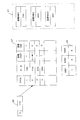
次に図面を参照してこの発明の実施の形態を説明する。図1は、この発明の一実施形態に従う、車載ゲートウェイ装置が接続される車両のネットワーク構成図の概略を示す。車両には、複数の電子制御装置(ECU)が搭載されており、たとえば、これらのECUには、エンジン制御用のECU、ドア制御用のECU、エアバック制御用のECU、ナビゲーションシステム用のECU等が含まれることができる。これらのECUは、中央処理装置(CPU)およびメモリを備えるコンピュータとして実現されている。 Next, an embodiment of the present invention will be described with reference to the drawings. FIG. 1 schematically shows a network configuration diagram of a vehicle to which an in-vehicle gateway device is connected according to an embodiment of the present invention. A plurality of electronic control units (ECUs) are mounted on the vehicle. For example, these ECUs include an ECU for engine control, an ECU for door control, an ECU for airbag control, and an ECU for navigation system Etc. can be included. These ECUs are realized as computers including a central processing unit (CPU) and a memory.
図の例の場合、ネットワークN1では、バスB1にECU1aが接続され、ネットワークN2では、バスB2にECU1bおよび1cが接続され、ネットワークN3では、バスB3にECU1dおよび1eが接続され、ネットワークN4では、バスB4にECU1fおよび1gが接続されている。この実施例では、バスB1〜B4は、バス型のネットワーク・トポロジによって車内LANを構成している。
In the example shown in the figure, in the network N1, the
さらに、バスB1〜B4は、ゲートウェイ装置10に接続されている。ネットワークN1〜N4は、ゲートウェイ装置10を介して互いに通信可能なように接続されており、したがって、ECU1a〜1gは、該ゲートウェイ装置10を介して、所定の通信プロトコルに従って互いに通信することができる。この実施例では、通信プロトコルとして、周知のCAN(controller area network)プロトコルを用いる。
Furthermore, the buses B1 to B4 are connected to the
各ECU1a〜1gは、「フレーム」と呼ばれるデータの単位で、データの送受信を行う。CANプロトコルに従うフレームは、図2に示されるような所定のフォーマットを有しており、フレームの開始を表すSOFフィールド、フレームを識別するためのIDなどを格納する調停(アービトレーション)フィールド、データ長などを格納する制御フィールド、転送すべきデータを格納するデータフィールド、エラーチェック用のCRCフィールド、ECUがデータを受信したことを伝えるために使用されるACKフィールド、およびフレームの終了を表すEOFフィールドから構成されている。
Each of the
ここで、フレーム中の調停フィールドに格納される上記のID(識別子)は、フレームの種類毎に設定され、データの内容や送信ECUを識別するために用いられるが、さらに、通信における調停において優先順位(優先度)を決めるための番号をも表している。この実施例では、IDの値が小さいデータほど、高い優先順位のデータであることを表す。 Here, the ID (identifier) stored in the arbitration field in the frame is set for each type of frame and is used to identify the data contents and the transmission ECU. It also represents a number for determining the rank (priority). In this embodiment, data with a smaller ID value represents higher priority data.
ゲートウェイ装置10は、一のネットワークからフレームデータを受信すると、この受信したフレームデータのIDを確認し、予め設定されたルーティングマップに従って、そのフレームデータを、他のネットワークに送信するよう構成されている。
When the
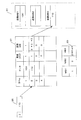
図3は、ゲートウェイ装置10の構成のブロック図を示す。なお、以下の図およびその説明において、構成要素を総称する場合には、aおよびbのような添え字を用いない符号で表記することとする。
FIG. 3 is a block diagram of the configuration of the
ゲートウェイ装置10は、CANモジュール11、ルート検索部12、および送信制御部13を備え、この例では、該ゲートウェイ装置10に、バスB1およびB2の入力バスと、バスB3およびB4の出力バスとが接続されている。この実施例では、CANモジュール11およびルート検索部12による処理は、ハードウェアで実現されており、送信制御部13による処理は、ソフトウェアで、すなわちゲートウェイ装置10に備えられるCPU(中央処理装置)がメモリ等に記憶されたコンピュータプログラムを実行することによって実現される。
The
CANモジュール11は、CANプロトコルに従ってバスに対するフレームデータの送受信制御を行うよう構成されている。CANモジュール11には、入力バスのチャネル毎に受信メッセージボックス(MB)21が、出力バスのチャネル毎に送信メッセージボックス(MB)31が、たとえばレジスタの形態で予め設けられている。CANモジュール11は、入力バスから受け取ったフレームデータを受信MB21に一時的に格納すると共に、送信MB31に一時的に格納されたデータを、その優先度の高い順に出力バスに送信する機能を有する。この例では、入力バスのチャネル毎に使用する受信MB21の数は、1個である。また、出力バスのチャネル毎に使用する送信MB31は、IDの数(すなわち、優先度の数)よりも少なく、この実施例では、送信MB1、送信MB2および送信MB3から成る3個である。したがって、一時に3つのフレームデータを格納することができる。
The CAN module 11 is configured to perform transmission / reception control of frame data with respect to the bus according to the CAN protocol. The CAN module 11 is provided in advance with a reception message box (MB) 21 for each channel of the input bus and a transmission message box (MB) 31 for each channel of the output bus, for example, in the form of a register. The CAN module 11 has a function of temporarily storing the frame data received from the input bus in the
図の例では、ゲートウェイ装置10がバスB1から受信するフレームデータを一時的に格納する受信MB21aと、ゲートウェイ装置10がバスB2から受信するフレームデータを一時的に格納する受信MB21bと、ゲートウェイ装置10がバスB3に送信するフレームデータを一時的に格納する送信MB31a(MB1〜MB3の3個の送信MBを有する)と、ゲートウェイ装置10がバスB4に送信するフレームデータを一時的に格納する送信MB31b(MB1〜MB3の3個の送信MBを有する)とが示されている。
In the illustrated example, the
CANモジュール11は、前述したように、ハードウェア構成を用いて実現されることができるが(たとえば、CAN通信を行うモジュールとして市販されているCANモジュールを利用することができる)、代替的に、ソフトウェアを用いて構成されるようにしてもよい。本願発明は、後述するように、既知のCANモジュールの機能を利用して、優先度の高い順にデータがバスに出力されるよう、送信制御部13によって送信メッセージボックスに対するデータの送信を制御するものである。 As described above, the CAN module 11 can be realized by using a hardware configuration (for example, a commercially available CAN module can be used as a module for performing CAN communication). Alternatively, You may make it comprise using software. In the present invention, as will be described later, the transmission control unit 13 controls the transmission of data to the transmission message box so that the data is output to the bus in the order of high priority by using the function of a known CAN module. It is.
ルート検索部12は、検索エンジン部23およびFIFOバッファ25を備えている。具体的には、検索エンジン部23は、各入力バスに対応するよう設けられ、ルーティングマップ24は、各検索エンジン部23に関連づけられて、RAM等のメモリに予め記憶されている。また、FIFOバッファ25は、各出力バスに対応するよう設けられており、所定数の段数(たとえば、32個)から構成され、一段につき1個のフレームデータを格納することができる。
The route search unit 12 includes a search engine unit 23 and a
この例では、検索エンジン部23aが、入力バスB1に対応するよう設けられ、検索エンジン部23bが、入力バスB2に対応するよう設けられている。検索エンジン部23aには、ルーティングマップ24aが対応づけられ、検索エンジン部23bには、ルーティングマップ24bが対応づけられており、両者のルーティングマップ24aおよび24bは、同じものでもよい。FIFOバッファ25aは、出力バスB3に対応するよう設けられ、FIFOバッファ25bは、出力バスB4に対応するよう設けられている。
In this example, the
受信MB21には、順次、対応するバスからのフレームデータが格納される。検索エンジン部23は、所定のタイミングで、該受信MB21からフレームデータを読み出し、該フレームデータのIDに基づいて、RAM等のメモリに予め記憶されたルーティングマップ24を参照し、フレームデータの転送先のバス(チャネル)を求める。
The
ここで、図4を参照すると、ルーティングマップ24の一例が概略的に示されている。ルーティングマップ24は、IDを規定するIDフィールド、受信バス(入力バス)のチャネル番号を規定する受信バスフィールド、および送信バス(出力バス)のチャネル番号を規定する送信バスフィールドを有しており、ID毎に、どのバスから受信してどのバスに送信するのかを規定している。好ましくは、ルーティングマップ24は、図に示すように、IDの昇順に従って、すなわち高い優先度から低い優先度に向けて配列される。 Here, referring to FIG. 4, an example of the routing map 24 is schematically shown. The routing map 24 includes an ID field that defines an ID, a reception bus field that defines a channel number of a reception bus (input bus), and a transmission bus field that defines a channel number of a transmission bus (output bus). For each ID, which bus is received and transmitted to which bus is defined. Preferably, the routing map 24 is arranged in the ascending order of ID, that is, from higher priority to lower priority, as shown in the figure.
さらに、この実施例では、ルーティングマップ24は、ラベルフィールドを有している。ラベルとIDは、1対1に対応づけられており、ラベルの値からIDの値は一義的に導き出され、その逆も同様である。 Furthermore, in this embodiment, the routing map 24 has a label field. The label and the ID are associated one-to-one, and the ID value is uniquely derived from the label value, and vice versa.
ラベルは、IDのビット数よりも少ないビット数から構成される。CANプロトコルの標準フレームの場合には、IDは11ビットで構成されるので、ラベルは、11ビットよりも少ないビット数で構成される。また、ID値の昇順に従って、ラベル値も昇順になるように、両者は対応づけられている。前述したように、この実施例では、ID値の昇順に従って優先度が低くなるので、ラベル値の昇順に従って優先度が低くなる。IDは、その連番に従って優先度が示され、結果として、実際に使用する優先度の数は211より少ない。したがって、ラベル値のビット数を、実際に使用する優先度(ID)の数に対応するよう設定することができる。また、ラベル値は、後述するように、配列構造を有する優先順格納領域27のエントリ番号として用いられるので、連続した値を持つよう設定される。
The label is composed of a number of bits smaller than the number of bits of the ID. In the case of a standard frame of the CAN protocol, since the ID is composed of 11 bits, the label is composed of fewer bits than 11 bits. Moreover, both are matched so that a label value may also become an ascending order according to the ascending order of ID value. As described above, in this embodiment, the priority decreases in the ascending order of the ID values, and therefore the priority decreases in the ascending order of the label values. ID, the priority in accordance with serial number is shown, as a result, the number of priorities to be actually used is less than 2 11. Therefore, the number of bits of the label value can be set so as to correspond to the number of priorities (ID) actually used. As will be described later, since the label value is used as the entry number of the priority
検索エンジン部23は、受け取ったフレームデータのIDと、ルーティングマップ24に記憶されたIDとを比較し、該フレームデータのIDと一致するIDを検索し、該検索したIDについて設定されたラベルと、送信バス(複数でもよい)のチャネル番号とを取得する。ルーティングマップ24がIDの昇順に従って配列されているので、比較は、IDの昇順に従って行われるのがよい。こうすることにより、受け取ったフレームデータの優先度が高いほど、より早期に、一致するIDを見つけることができ、検索処理の時間を短縮することができる。 The search engine unit 23 compares the ID of the received frame data with the ID stored in the routing map 24, searches for an ID that matches the ID of the frame data, and sets the label set for the searched ID. And the channel number of the transmission bus (s). Since the routing map 24 is arranged according to the ascending order of ID, the comparison should be performed according to the ascending order of ID. By doing so, the higher the priority of the received frame data, the earlier the matching ID can be found and the search processing time can be shortened.
検索エンジン部23は、受け取ったフレームデータに、取得したラベルを付加し、該ラベル付きフレームデータを、取得した送信バスのチャネル番号に対応するFIFOバッファ25に格納する。
The search engine unit 23 adds the acquired label to the received frame data, and stores the labeled frame data in the
この実施例では、検索エンジン部23が、各入力バスに対応するよう設けられているため、各入力バスからのフレームデータのルート検索処理を並列に実行することができる。代替的に、検索エンジン部23を、複数のバスチャネルに対して1個だけ設けるようにしてもよい。この場合、検索エンジン部23は、受信MB21aおよび21bの両方からのフレームデータについてルート検索を行う。この際、受信MB21aおよび21bと、検索エンジン部23との間に、検索エンジン23へのフレームデータの送信を制御するセレクタ部のようなものを設けてもよく、そのような形態は、たとえば特開2006−333438号公報に記載されている。なお、検索エンジン部23は、前述したように、たとえば当該公報に記載のようなハードウェアで実現されることができるが、代替的に、ソフトウェアによって実現してもよい。
In this embodiment, since the search engine unit 23 is provided so as to correspond to each input bus, it is possible to execute a route search process of frame data from each input bus in parallel. Alternatively, only one search engine unit 23 may be provided for a plurality of bus channels. In this case, the search engine unit 23 performs a route search on the frame data from both the
図3に戻り、送信制御部13には、出力バスのチャネル毎に、優先順格納領域(バッファ手段)27および送信MBテーブル29が設けられており、これらは、RAM等のメモリに実現される。 Returning to FIG. 3, the transmission control unit 13 is provided with a priority order storage area (buffer means) 27 and a transmission MB table 29 for each channel of the output bus, and these are realized in a memory such as a RAM. .
この例では、出力バスB3について、優先順格納領域27aおよび送信MBテーブル29aが設けられ、出力バスB4について、優先順格納領域27bおよび送信MBテーブル29bが設けられている。
In this example, a priority
ここで、図5(a)を参照すると、優先順格納領域27の構成が示されている。優先順格納領域27は、優先度の数分(すなわち、ラベル値(ID値)の数分)のエントリを有する配列構造となっている。各エントリの番号は、ラベル値に対応しており、これらのエントリは、優先度の高い順に、すなわちラベル値の昇順に従って配列されている。たとえば、ラベル値が、1〜10の値を取るとすると、1〜10の番号のエントリ領域が、優先順格納領域27には予め設定されている。
Here, referring to FIG. 5A, the configuration of the priority
さらに、優先順格納領域27は、各エントリ(ラベル値)について、データフィールド、受信フラグフィールド、送信MBフィールドを有する。データフィールドは、対応するFIFOバッファ25から受け取ったフレームデータを格納する領域である。受信フラグフィールドは、受信フラグが設定されるフィールドである。受信フラグフィールドの初期値(デフォルト値)はゼロであり、FIFOバッファ25から優先順格納領域27にフレームデータを格納した時に、値1が設定される。送信MBフィールドは、送信MBの番号が設定されるフィールドである。送信MBフィールドの初期値(デフォルト値)はゼロであり、対応するフレームデータが送信MB1〜MB3のいずれかに格納(複製)されたときに、該格納された先の送信MBの番号が設定される。この実施例では、送信MB31の数は3個であるので、送信MB1に格納されれば値1が設定され、送信MB2に格納されれば値2が設定され、送信MB3に格納されれば値3が設定される。
Furthermore, the priority
図5(b)には、送信MBテーブル29の構成が示されている。送信MBテーブル29は、送信MBの数分のフィールドを持つ。この実施例では、MB1〜MB3の3個の送信MBが存在するので、MB1フィールド、MB2フィールドおよびMB3フィールドを持つ。MB1フィールドには、送信MB1に現在格納されているフレームデータのラベル値が設定される。MB2およびMB3フィールドについても同様である。送信MBテーブル29を参照することにより、各送信MBに設定されているフレームデータのラベル値を特定することができる。 FIG. 5B shows the configuration of the transmission MB table 29. The transmission MB table 29 has fields for the number of transmission MBs. In this embodiment, since there are three transmission MBs, MB1 to MB3, it has an MB1 field, an MB2 field, and an MB3 field. The label value of the frame data currently stored in the transmission MB1 is set in the MB1 field. The same applies to the MB2 and MB3 fields. By referring to the transmission MB table 29, the label value of the frame data set in each transmission MB can be specified.
送信制御部13は、FIFOバッファ25aに格納されたフレームデータを、優先順格納領域27aの、該フレームデータのラベル値に対応するエントリ領域に一時的に格納する。送信制御部13は、送信MBテーブル29aを用い、優先度の高い順にデータが出力バスに送信されるよう、優先順格納領域27aから送信MB31aにデータを転送する優先順送信制御を実施する。CANモジュール11は、送信MB31aのMB1〜MB3に格納されたフレームデータを、優先度の高い順に、対応するバスB3に送信する。これらの制御は出力バス間で並列に実行され、よって図の例では、上記出力バスB3に対する制御と並列に、優先順格納領域27b、送信MBテーブル29bおよび送信MB31bを用いた出力バスB4に対する制御が実行される。
The transmission control unit 13 temporarily stores the frame data stored in the
以下では、
1)優先順格納領域27に受信したデータのIDの優先度が、送信MB31のいずれかの送信MBに格納されたデータのIDよりも高い場合、および、
2)優先順格納領域27に受信したデータのIDの優先度が、送信MB31のいずれかの送信MBに格納されたデータのIDと同じである場合、
について、優先順送信制御の具体的な内容を説明する。前者の1)については、図6〜図9を参照して説明し、後者の2)については、図10および図11を参照して説明する。
Below,
1) When the priority of the ID of the data received in the priority
2) When the priority of the ID of the data received in the priority
The specific contents of the priority order transmission control will be described. The former 1) will be described with reference to FIGS. 6 to 9, and the latter 2) will be described with reference to FIGS. 10 and 11.
図6〜図9を参照して、送信制御部13による、上記1)の場合の優先順送信制御の動作を説明する。ここで、ラベル値が1〜4に対応するID値は、それぞれ、100、110、200および300であるとする。また、フレームデータは、わかりやすいように、そのID値のみで図に示している。 With reference to FIGS. 6-9, the operation | movement of the priority order transmission control in the case of said 1) by the transmission control part 13 is demonstrated. Here, it is assumed that the ID values corresponding to the label values 1 to 4 are 100, 110, 200, and 300, respectively. Also, the frame data is shown in the figure with only its ID value for easy understanding.
図6は、所与の時間における一状態を示しており、FIFOバッファ25には、ラベル値2が付与されたID値が110(ID110と呼び、以下同様)のフレームデータが格納されていることを示す(前述したように、FIFOバッファ25は所定の段数を備えているが、図では、簡略化して、ID110のフレームデータの段のみを示している)。
FIG. 6 shows one state at a given time. The
優先順格納領域(以下、単に格納領域と呼ぶことがある)27には、ID100のフレームデータが、ラベル値が1のエントリ領域に格納され、ID200のフレームデータが、ラベル値が3のエントリ領域に格納され、ID300のフレームデータが、ラベル値が4のエントリ領域に格納されている。これらは、既に、対応するFIFOバッファ25から優先順格納領域27に転送されたものであるから、受信フラグフィールドの値は1となっている。
In a priority order storage area (hereinafter sometimes referred to simply as a storage area) 27, frame data of ID100 is stored in an entry area having a label value of 1, and frame data of ID200 is an entry area having a label value of 3. The frame data of ID300 is stored in the entry area with the label value of 4. Since these have already been transferred from the
送信メッセージボックス31において、送信MB1には、ID100のフレームデータが既に設定(格納)されており、送信MB2には、ID200のフレームデータが既に設定されており、送信MB3には、ID300のフレームデータが既に設定されている。したがって、優先順格納領域27の送信MBフィールドにおいて、ラベル値が1のエントリ領域では、送信MB1を表す値1が設定され、ラベル値が3のエントリ領域では、送信MB2を表す値2が設定され、ラベル値が4のエントリ領域では、送信MB3を表す値3が設定されている。
In the
優先順格納領域27のラベル値が2のエントリ領域のデータフィールドは空であり、よって、受信フラグフィールドの値はゼロである。この例では、送信MBフィールドの値はゼロ(初期値)であるが、以前に受信したデータのバスへの送信が完了している場合には、ゼロ以外の値が設定されていることがある。
The data field of the entry area whose label value is 2 in the priority
また、送信MBテーブル29のMB1フィールドには、送信MB1に設定されているフレームデータのラベル値1が設定されている。同様に、MB2フィールドには値3が設定され、MB3フィールドには値4が設定されている。
In the MB1 field of the transmission MB table 29, the
図7は、図6よりも時間が進んだ状態を示している。送信制御部13は、FIFOバッファ25から、フレームデータと、対応するラベル値を読み出し、該フレームデータを、優先順格納領域27の、該読み出したラベル値に対応するエントリ領域に格納する。この例では、FIFOバッファ25から読み出したフレームデータのラベル値は2であるので、ラベル値が2のエントリ領域に、ID110のフレームデータが格納される。この格納動作と共に、該エントリの受信フラグフィールドの値は1に更新され、送信MBフィールドの値はゼロに維持される(ゼロ以外の値であれば、ゼロにクリアされることとなる)。
FIG. 7 shows a state in which the time has advanced from FIG. The transmission control unit 13 reads the frame data and the corresponding label value from the
なお、FIFOバッファ25からフレームデータを読み出すタイミングは、FIFOバッファ25のオーバーフローを回避するよう、任意の適切な手法で設定されることができる。たとえば、検索エンジン部23によってFIFOバッファ25に所定数のデータを書き込んだことに応じて、割り込み信号を送信制御部13に発行し、これに応じて、送信制御部13は、FIFOバッファ25から順番にデータを読み出すことができる。このような手法の一例は、特開2006−333438号公報に記載されている。
Note that the timing for reading frame data from the
図8は、図7よりも時間が進んだ状態を表している。ラベル値2の新たなフレームデータが優先順格納領域27に既に受信されたので、図では、FIFOバッファ25を空として示している。
FIG. 8 shows a state in which the time has advanced from FIG. Since new frame data of
送信制御部13は、送信MBテーブル29に、ゼロが設定されたフィールドが存在するかどうかを調べることにより、送信MB31に空きがあるかどうかを判断すると共に、新たなフレームデータのラベル値2と、送信MBテーブル29のラベル値1,3,4とを比較する。このラベル値の比較により、新たなフレームデータのIDと、送信MB31に存在するフレームデータのIDとの間で、優先度を比較することができる。
The transmission control unit 13 determines whether or not there is a free space in the
送信MB31に空きがあり、同じID(優先度)のフレームデータが送信MB31に存在しなければ、新たなフレームデータを、該空いている送信MBに送信すればよい。しかしながら、この例では、送信MB31に空きは無い。したがって、上記ラベル値の比較に基づいて、新たなフレームデータのIDが、送信MB31のいずれかのフレームデータのIDよりも優先度が高いかどうかを判定し、高いと判定したならば、送信MB1〜MB3のうち、最も優先度の低いフレームデータが格納されている送信MBを選択する。
If there is a vacancy in the
この例では、新たなフレームデータのラベル値2は、送信MBテーブル29のMB2およびMB3フィールドに設定されているラベル値3および4よりも値が小さく、MB3フィールドに設定されているラベル値4は、MB2フィールドのラベル値3よりも大きい。したがって、送信MB3が、新たなフレームデータよりも優先度が低く、かつ最も優先度の低いフレームデータを格納した送信MBとして選択される。
In this example, the
送信制御部13は、こうして選択された送信MB3に既に設定されているID300のフレームデータのバスへの送信処理の停止を要求する信号を、CANモジュール11に発行する。この送信停止要求信号に応じて、CANモジュール11は、肯定応答を返すと共に、送信MB3のフレームデータの送信停止処理を実行し(図には、取消線によって停止を表している)、停止が完了したならば、停止完了信号を送信制御部13に返す。 The transmission control unit 13 issues a signal to the CAN module 11 for requesting to stop transmission processing of the frame data of ID300 already set in the transmission MB3 selected in this way to the bus. In response to this transmission stop request signal, the CAN module 11 returns an affirmative response and executes transmission stop processing of the frame data of the transmission MB3 (the stop is indicated by a cancel line in the figure), and the stop is completed. If so, a stop completion signal is returned to the transmission control unit 13.
送信制御部13は、停止完了信号を受けたならば、優先順格納領域27のラベル値4のエントリの送信MBフィールドの値を、3からゼロに更新する。これにより、バスへの送信が未完了であることが示され、該ラベル値4のフレームデータは、再び、送信MB31に送信されるのを待機する。
When receiving the stop completion signal, the transmission control unit 13 updates the value of the transmission MB field of the entry of the
さらに、送信制御部13は、送信MBテーブル29のMB3フィールドの値を、4からゼロに更新する。これにより、送信MB3には、フレームデータが設定されておらず、空きであることが示される。こうして、優先度の高いデータが受信されたときには、優先度の低いデータの送信を停止して、強制的に空きの送信MBを作る。 Further, the transmission control unit 13 updates the value of the MB3 field of the transmission MB table 29 from 4 to zero. Thereby, it is indicated that frame data is not set in the transmission MB3 and is empty. Thus, when data with high priority is received, transmission of data with low priority is stopped, and an empty transmission MB is forcibly created.
なお、送信制御部13は、送信MBからフレームデータが実際にバスに送信されている最中なのか、それとも送信MBにおいてフレームデータがバスへの送信待ちの状態にあるのかについては、判断することができない。送信MBからバスへの送信は、CANモジュール11によって制御されているからである。CANモジュール11は、送信停止要求信号を受け取ったとき、送信停止要求の対象となる送信MBが送信待ちの状態にあれば、送信停止処理を実行するが、送信中の状態にあれば、送信停止処理を実行しない。この場合、CANモジュール11は、送信停止要求信号に対し、否定応答を示す信号を返信する。上記の新たなフレームデータは、優先順格納領域27に維持されたまま、いずれかの送信MBが空きになるのを待つ。
The transmission control unit 13 determines whether frame data is actually being transmitted from the transmission MB to the bus or whether the frame data is waiting to be transmitted to the bus in the transmission MB. I can't. This is because transmission from the transmission MB to the bus is controlled by the CAN module 11. When receiving the transmission stop request signal, the CAN module 11 executes the transmission stop process if the transmission MB subject to the transmission stop request is in the transmission waiting state, but stops the transmission if it is in the transmitting state. Do not execute processing. In this case, the CAN module 11 returns a signal indicating a negative response to the transmission stop request signal. The new frame data is kept in the priority
図9は、図8よりも時間が進んだ状態を表している。送信MBテーブル29のMB3フィールドがゼロに設定されたことにより、送信制御部13は、送信MB3に空きが生じたと判断し、優先順格納領域27のラベル値2のエントリのデータフィールドに格納されているフレームデータを、送信MB3に複製することにより設定する(上書き)。送信制御部13は、優先順格納領域27のラベル値2のエントリの送信MBフィールドの値を、ゼロから3に更新する。これにより、ラベル値2のフレームデータが、送信MB3に転送されたことが示される。また、送信制御部13は、送信MBテーブル29のMB3フィールドの値をゼロから2に更新する。これにより、送信MB3には、ラベル値2のフレームデータが設定されたことが示される。
FIG. 9 shows a state in which the time has advanced from FIG. Since the MB3 field of the transmission MB table 29 is set to zero, the transmission control unit 13 determines that the transmission MB3 is free and is stored in the data field of the
なお、図7〜図9のような送信制御部13による処理が行われている間も、CANモジュール11は、送信MB31のMB1〜MB3に設定されたフレームデータのIDを互いに比較し、IDの優先度の高い順に、対応するバスにデータを送信(出力)する。バスへの出力が完了したならば、送信完了信号を、送信制御部13に発行する。送信制御部13は、送信完了となった送信MBに設定されていたフレームデータを、優先順格納領域27から削除すると共に、受信フラグフィールドの値をゼロにクリアする。また、送信MBテーブル29の、該送信完了となった送信MBに対応するMBフィールドの値をゼロにクリアする。たとえば、送信MB1のID100のフレームデータの出力バスへの送信が完了したならば、ラベル1のエントリ領域のデータフィールドから、ID100のフレームデータを削除し、受信フラグフィールドの値をゼロにクリアし、さらに、送信MBテーブル29のMB1フィールドの値をゼロにクリアする。こうして、ラベル値1のエントリ領域は空となり、送信MB1も空であることが示される。
While the processing by the transmission control unit 13 as shown in FIGS. 7 to 9 is being performed, the CAN module 11 compares the IDs of the frame data set in MB1 to MB3 of the transmission MB31 with each other, Data is transmitted (output) to the corresponding bus in descending order of priority. When the output to the bus is completed, a transmission completion signal is issued to the transmission control unit 13. The transmission control unit 13 deletes the frame data set in the transmission MB for which transmission has been completed from the priority
このように、送信MBに格納されているデータよりも高い優先度のデータが新たに受信された場合には、送信MBに既に格納されている、より優先度の低いデータが、該受信された新たなデータによって置き換えられる。したがって、低い優先度のデータによって送信MBが占領されているがために高い優先度のデータが待ちになるのを防止し、より早期にバスに出力することができる。結果として、より忠実に優先度に従ったバスへの転送を実現することができる。 Thus, when data having a higher priority than the data stored in the transmission MB is newly received, the lower priority data already stored in the transmission MB is received. Replaced by new data. Therefore, since the transmission MB is occupied by the low priority data, it is possible to prevent the high priority data from waiting and to output it to the bus earlier. As a result, transfer to the bus according to the priority can be realized more faithfully.
また、優先順格納領域27から送信MB31へのフレームデータの転送は複製によって行われ、優先順格納領域27には、該データが、バスへの出力が完了するまで保持される。したがって、送信MBに対する送信停止処理によって送信停止されたデータは、再度、送信MBに設定されるのを待つことができる。
The transfer of frame data from the priority
また、送信制御部13による優先順送信制御では、優先度の判断を、ラベルを用いて行っており、IDを何ら用いていないため、処理負荷を軽減することができる。従来は、新たに受信したデータのIDと、ゲートウェイ装置に既に受信されたデータのIDとを比較することにより、いずれのデータの優先度が高いかの判断を行っていた。しかしながら、IDはビット数が多く、比較回数が増えるほど処理負荷が増大するおそれがある。それに対し、ラベルは、IDよりもビット数が少ないので、ラベル値同士の比較処理は、ID同士の比較に比べて処理負荷が軽い。 Further, in the priority order transmission control by the transmission control unit 13, the priority is determined using the label and no ID is used, so that the processing load can be reduced. Conventionally, it is determined which data has higher priority by comparing the ID of newly received data with the ID of data already received by the gateway device. However, the ID has a large number of bits, and the processing load may increase as the number of comparisons increases. On the other hand, since the label has a smaller number of bits than the ID, the comparison processing between the label values is lighter than the comparison between the IDs.
また、優先順格納領域27は、ラベル値の昇順に対応したエントリ番号を持つ配列構造をなしている。したがって、FIFOバッファ25からのデータに付与されたラベル値に基づいて、データを格納すべき領域を、優先順格納領域27において高速に見極めることができる。仮に、このようなラベル値のエントリ番号を持つ配列構造を用いないとすると、受信したデータのIDと、該格納領域27中に存在するデータのIDとを比較しながら、同じIDのデータ領域を検索する必要がある。上記のようなラベル値のエントリ番号を持つ配列構造を用いれば、このようなIDの比較および検索は不要である。
The priority
さらに、優先順格納領域27から送信MB31へのデータの送信は、該優先順格納領域27に格納されたデータの優先度の高い順に行われるが、該格納領域27では、ラベル値の昇順に、すなわち優先度の高い順にデータが配列されているので、より高速に、送信すべきデータを見つけることができる。
Further, the data transmission from the priority
このように、ラベルを用いることにより、バスへの送信までの時間をより短縮することができる。しかしながら、他の実施形態では、ラベルを用いずに、IDを用いることによって、本願発明の優先順送信制御を実行してもよい。 Thus, by using the label, the time until transmission to the bus can be further shortened. However, in other embodiments, priority order transmission control of the present invention may be executed by using IDs without using labels.
次に、図10および図11を参照して、送信制御部13による、上記2)の場合の優先順送信制御の動作を説明する。上記2)は、受信したデータのIDの優先度と、送信MB31のいずれかの送信MBに設定されているデータのIDの優先度が、同じである場合を示す。
Next, with reference to FIG. 10 and FIG. 11, the operation of the priority order transmission control in the case of 2) by the transmission control unit 13 will be described. The above 2) shows a case where the priority of the received data ID is the same as the priority of the data ID set in one of the
この例では、FIFOバッファ25に、ラベル値2のフレームデータが受信されている。他方、優先順格納領域27には、同じラベル値2のフレームデータが既に格納されており、これは、送信MBフィールドの値が3であるように、送信MB3に現在設定されているデータである。優先順格納領域27の当該フレームデータは、未だ、バスへの送信が完了していない。送信MBテーブル29のMB3フィールドの値は2である。
In this example, the frame data having the
このような場合、送信制御部13は、FIFOバッファ25から、ラベル値2のフレームデータを読み出して、優先順格納領域27のラベル値2のエントリ領域を上書きして格納する。これに応じて、該エントリ領域の受信フラグフィールドは値1に維持されるが、送信MBフィールドの値は、ゼロにクリアされる。
In such a case, the transmission control unit 13 reads the frame data with the
さらに、送信制御部13は、前述したように、送信MBテーブル29を参照することにより、新たなフレームデータのラベル値2と、送信MBに既に設定されているフレームデータのラベル値1,0,2とを比較することにより、該新たなフレームデータのIDと同じIDのフレームデータが、送信MB3に設定されていることを判定する。この判定に応じて、送信制御部13は、送信MB3のバスへの送信を停止させる。前述したように、送信MB3に対して送信停止要求信号を発行し、CANモジュール11は、肯定応答を返すと共に、送信停止処理を実行する。CANモジュール11は、送信停止処理が完了したならば、停止完了信号を送信制御部13に送る。送信制御部13は、この停止完了信号を受信したことに応じて、ラベル値2のエントリ領域の送信MBフィールドの値をゼロに更新すると共に、送信MBテーブル29のMB3フィールドの値をゼロに更新する。
Further, as described above, the transmission control unit 13 refers to the transmission MB table 29, thereby labeling the new frame
その後、送信制御部13は、ラベル値2のフレームデータを、優先格納領域27から送信MB3に複製して設定(上書き)すると共に、ラベル値2のエントリ領域の送信MBフィールドの値をゼロから3に更新し、また、送信MBテーブル29のMB3フィールドの値をゼロから2に更新する。
Thereafter, the transmission control unit 13 duplicates and sets (overwrites) the frame data of the
図示していないが、送信MB3に設定されたラベル値2のフレームデータのバスへの送信が完了したならば、優先順格納領域27から当該フレームデータを削除すると共に、受信フラグフィールドをゼロにクリアする。送信MBテーブル29のMB3フィールドもゼロにクリアされる。
Although not shown, when transmission of the frame data of the
このように、送信MBに格納されたのと同じIDのフレームデータを受信した場合には、優先順格納領域27の対応するエントリ領域は上書きされ、該送信MBも、たとえ他に空きの送信MBがあっても(図では、送信MB2が空きとなっている)、上書きされる。
As described above, when the frame data having the same ID as that stored in the transmission MB is received, the corresponding entry area in the priority
なお、送信制御部13からの送信停止要求信号に応じて、CANモジュール11が否定応答を返した場合には、該ラベル値2のフレームデータは、図6〜図9を参照して説明した制御プロセスに従って、いずれかの送信MBに転送されるのを、優先順格納領域27において待機する。
If the CAN module 11 returns a negative response in response to a transmission stop request signal from the transmission control unit 13, the frame data of the
上記のような上書きを許容する理由について述べると、IDが同じということは、同じ種類のデータを表している。たとえば、エンジン回転数データは、所定の時間間隔で求められるが、これらのデータには、同じIDが割り振られる。他方、ECUによって実施される車両の制御は、よりリアルタイムな制御を実現するため、車両の現在の運転状態に基づいて行われるのが好ましく、そのため、車両の運転状態を表すデータとして、最新のデータを用いて制御を行うのが好ましい。たとえば、エンジン回転数データに基づく何らかの制御を実行するとき、最新のエンジン回転数データを用いるのが好ましい。したがって、古いデータが転送されている間に、新しいデータが該古いデータに追いついた場合には、該新しいデータで古いデータを上書きする。こうすることにより、古いデータの無駄な転送を防止することができると共に、より新しいデータを、ECUの制御処理に供することができる。 The reason why the overwriting as described above is permitted will be described. The same ID represents the same type of data. For example, the engine speed data is obtained at predetermined time intervals, and the same ID is assigned to these data. On the other hand, the vehicle control performed by the ECU is preferably performed based on the current driving state of the vehicle in order to realize more real-time control. Therefore, the latest data is used as data representing the driving state of the vehicle. It is preferable to perform control using. For example, when executing some control based on the engine speed data, it is preferable to use the latest engine speed data. Therefore, when new data catches up with the old data while the old data is being transferred, the old data is overwritten with the new data. In this way, wasteful transfer of old data can be prevented, and newer data can be used for ECU control processing.
なお、データの種類によっては、このような上書きを許容すべきでないものが存在しうるが、その場合、該上書きを許容しない種類のデータに対しては、上で述べた優先順送信制御とは別の任意の適切な手法によって、バスへの転送を行えばよい。 Depending on the type of data, there may be data that should not be allowed to be overwritten. In this case, for the type of data that does not allow overwriting, the priority order transmission control described above is used. Any other suitable technique may be used to transfer to the bus.
図11は、図10の代替形態を示す図である。図10と異なる点は、送信MBに空きがある場合には、同じIDのフレームデータの送信MBの送信停止の完了を待つことなく、該空きの送信MBにフレームデータを設定する点である。 FIG. 11 shows an alternative form of FIG. The difference from FIG. 10 is that when there is a vacant transmission MB, the frame data is set in the vacant transmission MB without waiting for the completion of the transmission stop of the transmission MB of the frame data with the same ID.
具体的には、FIFOバッファ25から優先順格納領域27への格納は、図10と同様に行われる。その後、送信制御部13は、前述したように、送信MBテーブル29を参照することにより、ゼロが設定されたフィールドが存在するかどうか調べると共に、新たなフレームデータのラベル値2と、送信MB31に既に設定されているフレームデータのラベル値1,0,2とを比較する。これにより、該新たなフレームデータのIDと同じIDのフレームデータが、送信MB3に設定されていると共に、送信MB2に空きがあることを判定する。これに応じて、送信制御部13は、同じIDのフレームデータを有する送信MB3に対し、前述したのと同様の手法で、送信停止要求信号を発行する。CANモジュール11は、肯定応答を返すと共に、送信停止処理を実行する。他方、送信制御部13は、CANモジュール11からの停止完了信号の受信を待つことなく、優先順格納領域27から、空いている送信MB2に、ラベル値2のフレームデータを複製して設定すると共に、ラベル値2のエントリ領域の送信MBフィールドを3から2に更新し、送信MBテーブル29のMB2フィールドを、ゼロから2に更新する。
Specifically, storage from the
CANモジュール11は、送信MB3の送信停止処理が完了したならば、停止完了信号を送信制御部13に送る。送信制御部13は、この停止完了信号に応じて、送信MBテーブル29のMB3フィールドの値を2からゼロに更新する。なお、ラベル値2のエントリ領域の送信MBフィールドの値は、該ラベル値2のフレームデータが送信MB2に設定されているので、そのまま維持される(ゼロにクリアされない)。
The CAN module 11 sends a stop completion signal to the transmission control unit 13 when the transmission stop process of the transmission MB3 is completed. The transmission control unit 13 updates the value of the MB3 field of the transmission MB table 29 from 2 to zero in response to the stop completion signal. Note that the value of the transmission MB field in the entry area of the
図示していないが、送信MB2のフレームデータのバスへの送信が完了した時に、ラベル値2のエントリ内のデータは削除されると共に、受信フラグフィールドはゼロにクリアされ、送信MBテーブル29のMB2フィールドもゼロにクリアされる。
Although not shown, when transmission of frame data of transmission MB2 to the bus is completed, data in the entry of
なお、送信MB3に対する送信停止要求に応じて、否定応答が返された場合には、送信MB3のデータは、送信停止されることなくそのまま送信され、送信完了に応じて、送信MBテーブル29のMB3フィールドの値がゼロにクリアされることとなる。その後、送信MB2に設定されたラベル値2のフレームデータのバスへの送信が完了したならば、優先順格納領域27から当該フレームデータを削除すると共に、受信フラグフィールドをゼロにクリアする。送信MBテーブル29のMB2フィールドもゼロにクリアされる。
If a negative response is returned in response to a transmission stop request for the transmission MB3, the data of the transmission MB3 is transmitted as it is without stopping the transmission, and MB3 in the transmission MB table 29 is transmitted upon completion of the transmission. The field value will be cleared to zero. Thereafter, when transmission of the frame data of the
図10の形態では、同じIDのフレームデータの送信MBへの転送を、CANモジュール11による送信MBの送信停止処理の完了を待ってから、すなわちCANモジュール11から停止完了信号を受けた後に行っていたが、図11の形態では、該送信停止処理の完了を待つ必要がない。CANモジュール11による送信停止処理には所定の時間を要するので、図11の形態によれば、該フレームデータの送信MBへの転送時間を短縮することができる。 In the form of FIG. 10, the frame data with the same ID is transferred to the transmission MB after waiting for completion of the transmission MB transmission stop processing by the CAN module 11, that is, after receiving a stop completion signal from the CAN module 11. However, in the form of FIG. 11, there is no need to wait for the completion of the transmission stop process. Since the transmission stop process by the CAN module 11 requires a predetermined time, according to the form of FIG. 11, the transfer time of the frame data to the transmission MB can be shortened.
次に、送信制御部13による、フレームデータがゲートウェイ装置10内に滞留している時間(滞留時間)を算出する機能について説明する。滞留時間の算出は、上記の優先順送信制御によって、優先度の低いフレームデータが、長期にわたってバスに送信されない状態を防止するために行われる。 Next, a function by which the transmission control unit 13 calculates the time during which frame data stays in the gateway device 10 (residence time) will be described. The residence time is calculated in order to prevent a state in which frame data having a low priority is not transmitted to the bus over a long period of time by the above-described priority order transmission control.
一実施例では、タイマ(図示せず)を設け、フレームデータ毎に、該データがゲートウェイ装置10に滞留している時間を計時する。滞留時間は、フレームデータが、バスに出力されることなくゲートウェイ装置にどの程度留まっているかどうかを判断する指標として計時されるものであるから、このような指標の役割を果たすのであれば、計時を任意の時点から開始することができる。
In one embodiment, a timer (not shown) is provided to measure the time that the data stays in the
たとえば、フレームデータがFIFOバッファ25から優先順格納領域27に格納された時点、または、フレームデータが、最初にいずれかの送信MBに設定された時点等を、計時の開始時点とすることができる。タイマは、ソフトウェア(プログラム)によって実現されてもよいし、ハードウェアで実現されてもよい。
For example, the time when the frame data is stored in the priority
こうして計時された滞留時間が所定値を超えても、該フレームデータが優先順格納領域27から削除されない(すなわち、バスへの送信が完了されない)場合、送信制御部13は、該フレームデータが設定された送信MBに対しては、送信停止要求信号を発行しない。この場合、受信した新たなフレームデータよりも優先度が低く、かつ、該送信停止したフレームデータの次に優先度の低いフレームデータがいずれかの送信MBに格納されているならば、該送信MBに対して送信停止要求信号を発行する。 If the frame data is not deleted from the priority order storage area 27 (that is, transmission to the bus is not completed) even if the residence time thus counted exceeds a predetermined value, the transmission control unit 13 sets the frame data. A transmission stop request signal is not issued for the transmitted MB. In this case, if the frame data having the lower priority than the received new frame data and the frame data having the next lower priority than the frame data stopped from transmission is stored in any one of the transmission MBs, the transmission MB Issue a transmission stop request signal.
たとえば、図8には、前述したように、送信MB3に対して送信停止要求信号を発行することが示されている。送信制御部13は、新たなデータのラベル値2と、送信MBテーブル29に設定されたラベル値1,3,4とを比較し、新たなデータよりも優先度が低く、かつ最も優先度の低いフレームデータを格納する送信MB3を判定している。滞留時間を用いるこの実施形態では、送信制御部13は、該判定した送信MB3に格納されているラベル値4のフレームデータの滞留時間が所定値を超えているかどうかを判断し、超えていなければ、前述したように送信MB3に対する送信停止要求信号を発行するが、超えているならば、送信MB3に対する送信停止要求信号の発行を禁止する。送信制御部13は、上記ラベル値の比較に基づき、新たなデータよりも優先度が低く、かつ送信停止したデータの次に優先度の低い送信MB(この例では、送信MB2)を判定し、該次に優先度の低い送信MB2に対して送信停止要求信号を発行する。こうすることにより、送信MB3のID300のフレームデータを、過渡の遅延を生じさせることなく、出力バスに送信することができる。
For example, FIG. 8 shows that a transmission stop request signal is issued to the transmission MB3 as described above. The transmission control unit 13 compares the
代替的に、タイマによる計時を、ラベル値(ID値)毎に行ってもよい。この場合、フレームデータにラベルが付された時点、フレームデータがFIFOバッファ25に受信された時点、FIFOバッファ25から優先順格納領域27に受信された時点、または、最初に送信MB31に設定された時点等を、計時の開始時点とすることができる。なお、この場合、図10や図11の形態のように同じIDのフレームデータを受信した場合には、同じタイマによって計時されることとなるので、該タイマをリセットして新たに計時を開始するのが好ましい。
Alternatively, timing by a timer may be performed for each label value (ID value). In this case, when the frame data is labeled, when the frame data is received by the
他の実施例では、タイマを設ける代わりに、ゲートウェイ装置10内において何らかの時点でフレームデータに付与されるタイムスタンプを利用して、上記の滞留時間を算出してもよい。たとえば、受信メッセージボックス21にデータが受信された時点やFIFOバッファ25に受信された時点等においてフレームデータにタイムスタンプが付与される場合には、該タイムスタンプを利用することができる。代替的に、送信制御部13が、フレームデータをFIFOバッファ25から優先順格納領域27に格納した時点や、最初に送信MBに設定された時点において、タイムスタンプを該フレームデータに付与するようにしてもよい。
In another embodiment, the dwell time may be calculated using a time stamp given to frame data at some point in the
この場合、たとえば図8の場合には、送信制御部13は、前述したように、判定した送信MB3に格納されているラベル値4のフレームデータに付与されたタイムスタンプを参照し、現在の時刻と該タイムスタンプとの間の差を、滞留時間として算出し、該滞留時間が所定値を超えているかどうかを判断する。超えていなければ、前述したように送信MB3に対する送信停止要求信号を発行するが、超えているならば、送信MB3に対する送信停止要求信号の発行を禁止する。この場合も同様に、送信制御部13は、上記ラベル値の比較に基づき、新たなデータよりも優先度が低く、かつ送信停止したデータの次に優先度の低いデータの送信MB(この例では、送信MB2)を判定し、該次に優先度の低いデータの送信MB2に対して送信停止要求信号を発行する。
In this case, for example, in the case of FIG. 8, the transmission control unit 13 refers to the time stamp given to the frame data of the
この実施例における、バスのチャネル毎に設けられる送信MB(メッセージボックス)の数は、MB1〜MB3の3個であり、これは、好ましい個数として選択されている。この理由を、図12および図13を参照して説明する。 In this embodiment, the number of transmission MBs (message boxes) provided for each channel of the bus is three, MB1 to MB3, and this is selected as a preferable number. The reason for this will be described with reference to FIGS.
図12は、チャネル毎に送信MBを2個(MB1とMB2)使用する場合の、送信MBからバスへのフレームデータの送信(出力)の一形態を示す図である。 FIG. 12 is a diagram showing one form of transmission (output) of frame data from the transmission MB to the bus when two transmission MBs (MB1 and MB2) are used for each channel.
時点t1において、送信MB1には、ID100のフレームデータが既に設定され、送信MB2には、ID200のフレームデータが既に設定されている。 At time t1, frame data of ID100 is already set in transmission MB1, and frame data of ID200 is already set in transmission MB2.
1つのバスには、一時に1つのフレームデータのみを出力することができる。ID100は、ID200よりも優先度が高いので、時点t1においては、送信MB1からID100のフレームデータのバスへの送信が開始され、送信MB2のID200のフレームデータは、送信待ちの状態にある。 Only one frame data can be output to one bus at a time. Since ID100 has a higher priority than ID200, at time t1, transmission of frame data of ID100 from the transmission MB1 to the bus is started, and frame data of ID200 of transmission MB2 is in a transmission waiting state.
ここで、時点t2において、前述したような送信制御部13による優先順送信制御によって、送信制御部13から、送信停止要求信号が送信MB2に対して発行されたとする。これに応じて、CANモジュール11は、肯定応答を送信制御部13に返すと共に、送信MB2の送信待ち状態を解消して、所定の停止処理を実行する。停止処理が完了したならば、CANモジュール11は、停止完了信号を送信制御部13に返す。送信制御部13は、該停止完了信号に応じて、時点t3において、ID110のフレームデータの優先順格納領域27から送信MB2への送信を開始する。これにより、送信MB2のID200のフレームデータは、上書きされていく。この上書き動作は、時点t5まで継続する。なお、同じビット数のデータについて、上書き動作(設定時間)は、バスへの送信時間よりも短い。
Here, it is assumed that at time t2, a transmission stop request signal is issued from the transmission control unit 13 to the transmission MB2 by the priority order transmission control by the transmission control unit 13 as described above. In response to this, the CAN module 11 returns an affirmative response to the transmission control unit 13, cancels the transmission waiting state of the transmission MB2, and executes a predetermined stop process. If the stop process is completed, the CAN module 11 returns a stop completion signal to the transmission control unit 13. In response to the stop completion signal, the transmission control unit 13 starts transmission of the frame data of
他方、時点t4において、ID100のフレームデータのバスへの送信が完了する。送信完了信号が送信制御部13に送られ、これに応じて、送信制御部13は、新たなID200のフレームデータの送信MB1への送信を開始する。ID200のフレームデータの送信MB2への設定(上書き)は、時点t6まで継続する。
On the other hand, at time t4, transmission of the frame data of ID100 to the bus is completed. A transmission completion signal is sent to the transmission control unit 13, and in response to this, the transmission control unit 13 starts transmitting frame data with a
図から明らかなように、ID100のフレームデータのバスへの送信が完了した時点t4では、どちらの送信MBにおいてもデータを設定中であり、バスに送信可能なデータが存在しない。バスへの送信が開始されるのは、送信MB2にID110のフレームデータの設定を終えた時点t5である。該設定を終えたことに応じて、CANモジュール11は、送信MB2からバスへのID110のフレームデータの送信を開始する。
As is apparent from the figure, at the time t4 when transmission of the frame data of ID100 to the bus is completed, data is being set in both transmission MBs, and there is no data that can be transmitted to the bus. Transmission to the bus is started at time t5 when setting of frame data of
時点t6において、ID200のフレームデータの送信MB1への設定が完了する。ID110のフレームデータがバスへ送信されている最中であるので、ID200のフレームデータは送信待ちの状態に入る。時点t7において、ID110のフレームデータの送信が完了したことに応じて、ID200のフレームデータの送信が開始される。 At time t6, setting of the frame data of ID200 to the transmission MB1 is completed. Since the frame data of ID110 is being transmitted to the bus, the frame data of ID200 enters a state of waiting for transmission. At time t7, transmission of frame data of ID200 is started in response to completion of transmission of frame data of ID110.
図の時点t4〜t5に示すように、使用する送信MBが2個の場合には、送信制御部13による優先順送信制御によって、両方のMBにデータを設定している最中という状態が生じるおそれがあり、よって、バスにデータを連続して送信することができない状態が生じうる。バスは解放状態となり、これは、処理効率の低下につながる。 As shown at time points t4 to t5 in the figure, when two transmission MBs are used, the priority control transmission control by the transmission control unit 13 causes a state in which data is being set in both MBs. There is a possibility that data cannot be continuously transmitted to the bus. The bus is released, which leads to a reduction in processing efficiency.
図13は、送信メッセージボックスを3個(MB1〜MB3)使用する場合の、送信MBからバスへのフレームデータの送信(出力)の一形態を示す図である。 FIG. 13 is a diagram showing one form of transmission (output) of frame data from the transmission MB to the bus when three transmission message boxes (MB1 to MB3) are used.
時点t1において、送信MB1には、ID100のフレームデータが既に格納され、送信MB2には、ID200のフレームデータが既に格納され、送信MB3には、ID300のフレームデータが既に格納されている。 At time t1, frame data of ID100 is already stored in transmission MB1, frame data of ID200 is already stored in transmission MB2, and frame data of ID300 is already stored in transmission MB3.
ID100は、ID200およびID300よりも優先度が高いので、時点t1においては、送信MB1からID100のフレームデータのバスへの送信が開始され、送信MB2のID200のフレームデータおよび送信MB3のID300のフレームデータは、送信待ちの状態にある。 Since ID100 has a higher priority than ID200 and ID300, transmission of frame data of ID100 from the transmission MB1 to the bus is started at time t1, and frame data of ID200 of transmission MB2 and frame data of ID300 of transmission MB3 Is waiting to be sent.
ここで、時点t2において、前述したような送信制御部13による優先順送信制御によって、送信制御部13から、送信停止要求信号が送信MB3に対して発行されたとする。これに応じて、CANモジュール11は、この送信停止要求に対して肯定応答を送信制御部13に返すと共に、送信MB3の送信待ち状態を解消して、所定の停止処理を実行する。停止処理が完了したならば、CANモジュール11は、停止完了信号を送信制御部13に返す。送信制御部13は、該停止完了信号に応じて、時点t3において、ID110のフレームデータの優先順格納領域27から送信MB3への送信を開始する。これにより、送信MB3のID300のフレームデータは、上書きされていく。この上書き動作は、時点t5まで継続する。
Here, it is assumed that at time t2, a transmission stop request signal is issued from the transmission control unit 13 to the transmission MB3 by the priority order transmission control by the transmission control unit 13 as described above. In response to this, the CAN module 11 returns an affirmative response to the transmission stop request to the transmission control unit 13, cancels the transmission waiting state of the transmission MB3, and executes a predetermined stop process. If the stop process is completed, the CAN module 11 returns a stop completion signal to the transmission control unit 13. In response to the stop completion signal, the transmission control unit 13 starts transmission of the frame data of
他方、時点t4において、ID100のフレームデータのバスへの送信が完了する。CANモジュール11は、送信完了に応じて、送信MB2のID200のフレームデータのバスへの送信を速やかに開始する。また、ID100のフレームデータの送信完了信号が送信制御部13に送られ、これに応じて、送信制御部13は、新たなID300のフレームデータの送信MB1への送信を開始する。ID300のフレームデータの送信MB1への設定(上書き)は、時点t6まで継続する。
On the other hand, at time t4, transmission of the frame data of ID100 to the bus is completed. The CAN module 11 promptly starts transmission of the frame data of the
図から明らかなように、ID100のフレームデータのバスへの送信が完了した時点t4では、送信MB3は、優先順送信制御によって新たなフレームデータの設定中であるが、送信MB2のフレームデータのバスへの送信は、直ちに開始することができる。したがって、優先順送信制御によっていずれかの送信MBが設定中になっても、残りの1つの送信MBからのバスへの送信を連続して実行することができる。 As is apparent from the figure, at the time t4 when transmission of the frame data of ID100 to the bus is completed, the transmission MB3 is in the process of setting new frame data by priority transmission control, but the frame data bus of the transmission MB2 is set. Transmission to can be started immediately. Therefore, even if any one of the transmission MBs is being set by the priority order transmission control, transmission from the remaining one transmission MB to the bus can be continuously executed.
時点t5において、送信MB3のID110のフレームデータの設定が完了すると、ID200のフレームデータが送信中であるので、送信待ちの状態に入る。また、時点t6において、送信MB1のID300のフレームデータの設定が完了すると、ID200のフレームデータがまだ送信中であるので、送信待ちの状態に入る。ID200のフレームデータの送信は、時点t7において完了する。送信待ちになっているのは、ID300とID110のフレームデータである。CANモジュール11は、IDを比較し、優先度の高い方のフレームデータ、すなわちID110のフレームデータを選択して、これを、バスに送信する。ID300のフレームデータの送信待ち状態は、継続される。
At the time t5, when the setting of the frame data of
このように、使用する送信MBの数が3個である場合には、いずれかの送信MBが優先順送信制御によって送信待ちの状態から設定中の状態に移行しても、送信待ちとなっている他の送信MBからのフレームデータをバスに送信することができる。したがって、図12を参照して説明したような、バスが解放された状態が生じず、連続送信を行うことが可能である。このように、送信MBの数は、少なくとも3個設けるのが好ましい。 In this way, when the number of transmission MBs to be used is three, even if any of the transmission MBs shifts from the transmission standby state to the setting state by priority transmission control, the transmission MB is in a transmission standby state. Frame data from other transmission MBs can be transmitted to the bus. Therefore, a state in which the bus is released as described with reference to FIG. 12 does not occur, and continuous transmission can be performed. Thus, it is preferable to provide at least three transmission MBs.
他方、使用する送信MBの数を4個以上にしても、上記のような連続送信は可能であるが、この場合、優先順送信制御において、どの送信MBに格納されたデータを置き換えるかを判断するための比較対象が増大するので処理負荷が増大するおそれがある。このような処理負荷は、使用する送信MBの数を増やすほど、増大する。また、CANモジュール11も、バスにデータの送信を開始する際に、最も優先度の高いIDのフレームデータを選択するが、この際も、比較対象となるIDの数が増大するので、処理負荷が増えるおそれがある。したがって、使用する送信MBの数を3個にとどめるのが、連続送信を可能にしつつ、処理負荷を抑制する観点から好ましい。 On the other hand, even if the number of transmission MBs to be used is four or more, continuous transmission as described above is possible. In this case, it is determined in which transmission MB the data stored in the priority order transmission control is replaced. Because the number of comparison targets for doing so increases, the processing load may increase. Such processing load increases as the number of transmission MBs used increases. The CAN module 11 also selects the frame data having the highest priority ID when starting transmission of data to the bus. However, since the number of IDs to be compared increases, the processing load is also increased. May increase. Therefore, it is preferable to use only three transmission MBs from the viewpoint of suppressing processing load while enabling continuous transmission.
次に、図14は、送信制御部13によって実行される、FIFOバッファ25から優先順格納領域27にフレームデータを受信する制御プロセスのフローチャートである。このプロセスは、たとえば前述したように検索エンジン部23から割り込み信号を受けたことに応じて開始される。
Next, FIG. 14 is a flowchart of a control process executed by the transmission control unit 13 to receive frame data from the
ステップS11において、FIFOバッファ25からフレームデータを取得する。前述したように、フレームデータには、ルーティングマップ24の検索によって取得された、該フレームデータのIDに対応するラベルが付与されている。
In step S11, frame data is acquired from the
ステップS12において、該取得したフレームデータに付与されたラベルを取得する(読む)。ステップS13において、優先順格納領域27の、取得したラベルに対応するエントリ領域に、該フレームデータを格納する。前述したように、該エントリ領域に既にフレームデータが存在する場合には、該取得したフレームデータで上書きされる。
In step S12, a label attached to the acquired frame data is acquired (read). In step S13, the frame data is stored in the entry area corresponding to the acquired label in the priority
ステップS14において、該エントリ領域の受信フラグフィールドの値を1に設定する。ステップS15において、該エントリ領域の送信MBフィールドの値を、ゼロにクリアする。こうして、図7に示すように、新たなフレームデータが格納領域27に格納される。
In step S14, the value of the reception flag field of the entry area is set to 1. In step S15, the value of the transmission MB field in the entry area is cleared to zero. Thus, new frame data is stored in the
図15は、送信制御部13によって実行される、優先順格納領域27から送信MB31にフレームデータを送信する制御プロセスのフローチャートである。該プロセスは、たとえば所定時間間隔で、繰り返し実行される。
FIG. 15 is a flowchart of a control process executed by the transmission control unit 13 to transmit frame data from the priority
説明をわかりやすくするため、優先順格納領域27および送信MB31のいずれにもデータが格納されていない状況から、該プロセスを辿る。このような状況では、送信MBのいずれにもまだデータが格納されていないので、ステップS21およびS22の判断はNoとなり、ステップS25の判断もNoとなり、このプロセスを抜ける。
In order to make the explanation easy to understand, the process is followed from a situation in which no data is stored in either the priority
その後、図14の受信制御プロセスによって、優先順格納領域27に新たなフレームデータが格納されたとする。この場合、ステップS25の判断はYesとなり、ステップS26の判断はNoとなる。ステップS41に進むこととなり、ここで、いずれの送信MB1〜MB3にも設定されていないデータが格納領域27に存在するかどうかを判断する。これは、格納領域27の受信フラグフィールドの値が1であって、送信MBフィールドの値がゼロであるフレームデータが存在するかどうかによって判断されることができる。このようなデータが存在しないときには、送信MBに転送すべきデータが存在しないことを示すので、当該プロセスを抜ける。他方、上のように新たなフレームデータが格納領域27に格納されたときには、この判断はYesとなる。
Thereafter, it is assumed that new frame data is stored in the priority
ステップS42において、格納領域27に格納されているが、いずれの送信MB1〜MB3にも設定されていないフレームデータのうち、最も優先度の高いフレームデータ、すなわち最も小さいラベル値を持つフレームデータを選択して、それを、いずれかの送信MBに設定する(S26の判断がNoであるので、すべての送信MB1〜MB3が空いているため、どの送信MBでもよいが、通常、送信MB1から使用する)。こうして、上記の新たなフレームデータは、いずれかの送信MBに設定される。
In step S42, the frame data having the highest priority, that is, the frame data having the smallest label value is selected from the frame data stored in the
ステップS43において、フレームデータが設定された送信MBの番号(MB1に設定されたならば、値1)を、格納領域27の該フレームデータに対応する送信MBフィールドに設定する(更新)。ステップS44において、送信MBテーブル29の、該設定された送信MB番号のフィールドの値を、該設定されたフレームデータのラベル値に更新する。こうして、優先度の高い順に、優先順格納領域27から送信MB31にデータが転送される。前述したように、送信MBに設定されたフレームデータは、CANモジュール11の制御によって、優先度の高い順にバスに出力される。
In step S43, the number of the transmission MB in which the frame data is set (
その後、いずれかの送信MB1〜MB3にデータが格納されている状態で、新たなフレームデータが格納領域27に受信されると、ステップS25およびS26の判断はYesとなる。ステップS27において、送信MB1〜MB3に設定されたフレームデータのIDと同じIDのフレームデータが、格納領域27に存在しているかどうかを判断する。これは、送信MBテーブル29のMB1〜MB3フィールドに設定されたラベル値と、格納領域27の受信フラグの値が1のラベル値とを比較することにより判断することができる。また、存在している場合には、ステップS28において、該存在している判断されたIDのフレームデータが、送信MBに未だ設定されていないかどうかを判断する。これは、当該IDの送信MBフィールドの値がゼロかどうかで判断することができる。
Thereafter, when new frame data is received in the
ステップS27またはステップS28の判断がNoであれば、送信MB1〜MB3に未だ設定されていないIDのフレームデータが新たに格納領域27に存在することを示す。ステップS35において、送信MBテーブル29のいずれかのフィールドにゼロが設定されているかどうかを判断することにより、3つの送信MB1〜MB3のいずれかに空きがあるかどうかを判断する。空きがあれば、ステップS41以下を実行する。すなわち、格納領域27に受信されているが、送信MBに未だ設定されていないフレームデータを、優先度の高い順に、空いている送信MBに設定する。
If the determination in step S27 or step S28 is No, it indicates that frame data with an ID not yet set in the transmission MB1 to MB3 exists in the
ステップS35において、送信MB1〜MB3のいずれにも空きが無ければ、ステップS36〜S38において、図8を参照して説明したように、強制的に空きの送信MBを作るための動作を実行する。すなわち、ステップS36において、送信MB1〜3のいずれかに設定されたフレームデータよりも、優先度の高いフレームデータが格納領域27に存在するかどうかを調べる。これは、送信MBテーブル29のラベル値と、格納領域27の受信フィールドの値が1のラベル値とを比較することにより行うことができる。存在していなければ(S36がNo)、送信MB1〜MB3に設定されたフレームデータの優先度の方が高いということなので、強制的に空きの送信MBを作ることは行わず、当該プロセスを抜ける。
If there is no free space in any of the transmission MB1 to MB3 in step S35, an operation for forcibly creating a free transmission MB is executed in steps S36 to S38 as described with reference to FIG. That is, in step S36, it is checked whether or not frame data having a higher priority than the frame data set in any of the
存在していれば、ステップS37において、その存在している優先度の高いフレームデータの送信MBフィールドの値がゼロかどうかを調べることにより、そのフレームデータが、いずれの送信MBにも未だ設定されていないかどうかを判断する。設定されていれば(S37がNo)、強制的に空きの送信MBを作る必要はないので、当該プロセスを抜ける。 If it exists, in step S37, the frame data is still set in any transmission MB by checking whether the value of the transmission MB field of the existing high priority frame data is zero. Judge whether or not. If it is set (No in S37), there is no need to forcibly create an empty transmission MB, and the process is exited.
ステップS36およびS37の判断が両方ともYesであれば、送信MB1〜MB3に設定されているフレームデータよりも優先度の高いフレームデータが、格納領域27に存在していることを示す。ステップS38において、送信MBテーブル29を参照し、最も優先度の低い、すなわち最もラベル値の大きい送信MBを選択し、選択した送信MBに対して送信停止要求信号を発行し、その後、当該プロセスを抜ける。
If both determinations in steps S36 and S37 are Yes, it indicates that frame data having a higher priority than the frame data set in the transmission MB1 to MB3 exists in the
再び当該プロセスを実行したとき、上記のように送信停止要求信号が発行されているので、ステップS21の判断がYesとなる。ステップS31において、送信停止が完了したかどうかを判断する。前述したように、CANモジュール11は、送信停止要求信号に応じて肯定応答を返した場合には停止処理を開始し、停止処理が完了したならば、停止完了信号を送信制御部13に発行する。 When the process is executed again, since the transmission stop request signal is issued as described above, the determination in step S21 is Yes. In step S31, it is determined whether or not the transmission stop has been completed. As described above, the CAN module 11 starts the stop process when an affirmative response is returned in response to the transmission stop request signal, and issues a stop completion signal to the transmission control unit 13 when the stop process is completed. .
この停止完了信号を受け取るまで、または送信停止要求信号に対して否定応答を受けた場合には、ステップS31の判断はNoとなり、よって、ステップS25以下の処理が通常通り行われる。停止完了信号を受信したならば、ステップS31の判断はYesとなる。 Until this stop completion signal is received or when a negative response is received in response to the transmission stop request signal, the determination in step S31 is No, and the processing in step S25 and subsequent steps is performed as usual. If the stop completion signal is received, the determination in step S31 is Yes.
ステップS32において、前述したように、送信停止の対象となった送信MBのフレームデータについて、格納領域27における送信MBフィールドの値をゼロにクリアにし、ステップS33において、送信MBテーブル29の、送信停止が行われた送信MBのラベルの値をゼロにクリアする。こうして、当該フレームデータのバスへの送信が未完了であることを示しつつ、該フレームデータは格納領域27にそのまま維持される。
In step S32, as described above, the transmission MB field value in the
送信停止によって、その送信MBは空きとなるので、ステップS35の判断がYesとなり、ステップS41以下の処理において、上記の新たなフレームデータは、空きとなった送信MBに設定されることとなる。 Since the transmission MB becomes empty due to the stop of transmission, the determination in step S35 becomes Yes, and the above-described new frame data is set to the empty transmission MB in the processing after step S41.
その後、CANモジュール11によって、この送信MBに設定されたフレームデータのバスへの送信が完了したならば、ステップS22の判断がYesとなり、ステップS23において、送信完了したフレームデータを、格納領域27から削除すると共に、対応する受信フラグフィールドの値を、1からゼロに更新する。ステップS24において、送信MBテーブル29の、送信完了した送信MBのラベル値をゼロにクリアする。
Thereafter, if the CAN module 11 completes the transmission of the frame data set in the transmission MB to the bus, the determination in step S22 is Yes, and the frame data that has been transmitted is stored in the
他方、ステップS27およびS28の両方の判断がYesの場合、すなわち、いずれかの送信MB1〜MB3に設定されたIDと同じIDのフレームデータが格納領域27に存在し、かつそのフレームデータが未だ送信MB1〜MB3に設定されていない場合には、このフローでは、図10に従って処理される。すなわち、ステップS29において、格納領域27の当該フレームデータを、同じIDのフレームデータが格納されている送信MBに上書き設定するため、その送信MBに対し、送信停止要求信号を発行する。送信停止要求信号を発行した後は、ステップS21、S31〜S33の処理により、その送信MBが空きにされ、ステップS41以下の処理で、格納領域27の当該フレームデータで、その空きにされた送信MBが上書きされる。
On the other hand, if both the determinations in steps S27 and S28 are Yes, that is, the frame data having the same ID as the ID set in any of the transmission MB1 to MB3 exists in the
前述した滞留時間を用いる実施形態にも、図14および図15のプロセスは、同様に適用されることができる。この場合、図15において、ステップS38において送信停止要求を発行する対象となる、最も優先度の低いフレームデータが格納された送信MBを選択する際に、該データの滞留時間を参照し、これが所定値を超えている場合には、次に優先度の低いフレームデータの送信MBを選択する。こうして選択した送信MBに対し、送信停止要求信号を発行する。 The embodiments of FIGS. 14 and 15 can be similarly applied to the embodiments using the residence time described above. In this case, in FIG. 15, when selecting the transmission MB storing the frame data with the lowest priority, which is the target of issuing the transmission stop request in step S38, the dwell time of the data is referred to, If the value is exceeded, the transmission MB of the frame data with the next lowest priority is selected. A transmission stop request signal is issued for the selected transmission MB.
また、図11を参照して説明した、同じIDのフレームデータを受信した場合の図10の代替形態についても、図14および図15のプロセスは同様に適用されることができる。この場合、空きの送信MBへのデータの設定が、同じIDの送信MBの送信停止処理の完了を待つことなく行われる。そのため、ステップS28の判断がYesになったとき、ステップS29を実行して、同じIDのフレームデータが格納されている送信MBの送信停止要求を発行すると共に、いずれかの送信MB1〜MB3に空きがあるかどうかを判断する。空きがあれば、ステップS41以下を実行して、その空いている送信MBに、格納領域27から、当該IDのフレームデータを送信する。その後、該送信停止要求を発行した送信MBについては、ステップS31の判断がYesになるが、該送信停止した送信MBに格納されていたフレームデータについては、ステップS32は実行されない。前述したように、優先順格納領域27の該当エントリ領域には、上書きにより新しいデータが既に格納されて該空きの送信MBに設定されており、該エントリ領域の送信MBフィールドには、ステップS43によって該送信MBの番号が既に設定されているからである。
Also, the processes of FIGS. 14 and 15 can be similarly applied to the alternative form of FIG. 10 when the frame data having the same ID is received as described with reference to FIG. In this case, data is set in the empty transmission MB without waiting for the completion of the transmission stop process for the transmission MB with the same ID. Therefore, when the determination in step S28 is Yes, step S29 is executed to issue a transmission stop request for a transmission MB in which frame data with the same ID is stored, and one of the transmission MB1 to MB3 is free. Determine if there is. If there is a vacancy, step S41 and the subsequent steps are executed, and the frame data of the ID is transmitted from the
上記の実施形態は、通信プロトコルとしてCANを用いているが、本願発明はこれに限定されず、他の通信プロトコルを用いた場合にも適用可能である。 In the above embodiment, CAN is used as a communication protocol, but the present invention is not limited to this, and the present invention is also applicable when other communication protocols are used.
以上のように、この発明の特定の実施形態について説明したが、本願発明は、これら実施形態に限定されるものではない。 As described above, specific embodiments of the present invention have been described. However, the present invention is not limited to these embodiments.
1a〜1g ECU
10 車載ゲートウェイ装置
11 CANモジュール
12 ルート検索部
13 送信制御部
27 優先順格納領域
29 送信MBテーブル
31 送信メッセージボックス
1a-1g ECU
DESCRIPTION OF
Claims (4)
当該他のネットワークへ送信すべきデータをそれぞれ格納する複数の送信メッセージボックスと、
当該各送信メッセージボックスに格納したデータを、当該データに付された識別子(ID)が表す優先度に応じて、順次、前記他のネットワークに送信する送信インタフェースと、
前記一のネットワークから受信したデータを順次格納し、当該データが他のネットワークへ送信されるまで保持するバッファ手段と、
前記受信したデータを当該データに付された前記識別子に応じて前記バッファ手段に格納すると共に、前記バッファ手段に格納されたデータを前記送信メッセージボックスに格納する制御手段と、
を備えた車載ゲートウェイ装置であって、
前記バッファ手段は、前記受信したデータをそれぞれ格納する複数の格納領域で構成された配列構造を為し、前記格納領域毎に格納すべきデータの優先度が予め定められ、かつ、前記配列構造のインデックスに沿って優先度順に、前記受信したデータが格納されるよう構成されており、
前記複数の送信メッセージボックスは、前記識別子よりも少ない数で構成され、
前記制御手段は、前記一のネットワークから受信したデータに、当該データに付された識別子に対応し、かつ該識別子よりもビット数の少ないラベルを付与し、前記データの優先度を該ラベルの値により特定して動作するよう構成され、かつ、
前記一のネットワークから新たなデータを受信する毎に、当該データを前記バッファ手段に格納すると共に、前記バッファ手段に格納されているデータのうち、前記インデックスの若い順に特定される、前記送信メッセージボックスの数に応じた数の一群のデータが、前記送信メッセージボックスにおいて格納されている状態となるように、
前記新たなデータを受信したとき、当該受信した新たなデータの識別子と、前記複数の送信メッセージボックスに格納されている各データの識別子とを比較し、前記受信した新たなデータと識別子が同じであるデータが前記複数の送信メッセージボックスのいずれかに格納されている場合には、当該識別子が同じであるデータの前記他のネットワークへの送信を停止すると共に、前記受信した新たなデータを前記バッファ手段から複製し、前記識別子が同じであるデータに、当該複製した前記受信した新たなデータを上書きして格納し、
前記受信した新たなデータと識別子が同じであるデータが前記送信メッセージボックスのいずれにも格納されていない場合には、前記受信した新たなデータを前記バッファ手段から複製し、前記複数の送信メッセージボックスに格納されているデータのうち、前記受信した新たなデータよりも低い優先度を持ち、かつ最も優先度の低い識別子を持つデータに、前記複製した前記受信した新たなデータを上書きして格納する、
車載ゲートウェイ装置。 A function to transfer data received from one network to another network;
A plurality of transmission message boxes each storing data to be transmitted to the other network;
A transmission interface that sequentially transmits the data stored in each transmission message box to the other network according to the priority represented by the identifier (ID) attached to the data;
Buffer means for sequentially storing data received from the one network and holding the data until the data is transmitted to another network;
Control means for storing the received data in the buffer means in accordance with the identifier attached to the data, and storing the data stored in the buffer means in the transmission message box ;
An in-vehicle gateway device comprising:
The buffer means has an array structure composed of a plurality of storage areas each storing the received data, the priority of data to be stored for each storage area is determined in advance, and the array structure The received data is configured to be stored in order of priority along the index,
The plurality of transmission message boxes are configured with a number smaller than the identifier,
The control means assigns to the data received from the one network a label corresponding to the identifier attached to the data and having a smaller number of bits than the identifier, and sets the priority of the data to the value of the label Is configured to operate in a specific manner, and
Each time new data is received from the one network, the data is stored in the buffer means, and the transmission message box is specified in ascending order of the index among the data stored in the buffer means. So that a group of data corresponding to the number of data is stored in the transmission message box ,
When the new data is received, the identifier of the received new data is compared with the identifier of each data stored in the plurality of transmission message boxes, and the identifier is the same as the received new data. When certain data is stored in any of the plurality of transmission message boxes, transmission of data having the same identifier to the other network is stopped, and the received new data is stored in the buffer. Copied from the means, and the data having the same identifier is overwritten with the received new data and stored,
When data having the same identifier as the received new data is not stored in any of the transmission message boxes, the received new data is copied from the buffer means, and the plurality of transmission message boxes Of the received data, the data having a lower priority than the received new data and having the lowest priority identifier is overwritten and stored on the copied new received data. ,
In-vehicle gateway device.
前記制御手段は、前記滞留時間が所定時間を超えるデータを格納している前記送信メッセージボックスがあるときは、当該送信メッセージボックスを除く前記送信メッセージボックスを対象として、前記バッファ手段から前記送信メッセージボックスへのデータの格納を実行する、
請求項1に記載の車載ゲートウェイ装置。 Means for measuring the residence time of the data received from the one network in the in-vehicle gateway device;
Wherein, when the residence time is the transmission message box that contains the data that exceeds the predetermined time, as a target the transmission message box excluding the transmission message box, the transmission message box from said buffer means To store data in
The in-vehicle gateway device according to claim 1.
請求項1または2に記載の車載ゲートウェイ装置。 When the control means stores new data from the buffer means to the transmission message box , the old data having the same priority as the new data is received before the new data. the are stored in either the transmit message box, and, when there is the transmission message box not storing the data to be transmitted, without overwriting the old data with the new data, the new Storing data in a transmission message box that does not store data to be transmitted, and instructing the transmission interface to stop transmission of the old data.
The in-vehicle gateway device according to claim 1 or 2.
請求項1から3のいずれかに記載の車載ゲートウェイ装置。 The transmission message box is composed of three pieces.
The in-vehicle gateway device according to any one of claims 1 to 3.
Priority Applications (1)
| Application Number | Priority Date | Filing Date | Title |
|---|---|---|---|
| JP2009091589A JP5075868B2 (en) | 2009-04-03 | 2009-04-03 | In-vehicle gateway device |
Applications Claiming Priority (1)
| Application Number | Priority Date | Filing Date | Title |
|---|---|---|---|
| JP2009091589A JP5075868B2 (en) | 2009-04-03 | 2009-04-03 | In-vehicle gateway device |
Publications (2)
| Publication Number | Publication Date |
|---|---|
| JP2010245793A JP2010245793A (en) | 2010-10-28 |
| JP5075868B2 true JP5075868B2 (en) | 2012-11-21 |
Family
ID=43098338
Family Applications (1)
| Application Number | Title | Priority Date | Filing Date |
|---|---|---|---|
| JP2009091589A Active JP5075868B2 (en) | 2009-04-03 | 2009-04-03 | In-vehicle gateway device |
Country Status (1)
| Country | Link |
|---|---|
| JP (1) | JP5075868B2 (en) |
Families Citing this family (2)
| Publication number | Priority date | Publication date | Assignee | Title |
|---|---|---|---|---|
| JP5708273B2 (en) * | 2011-06-06 | 2015-04-30 | トヨタ自動車株式会社 | Communication apparatus, information processing apparatus, and data transmission method |
| JP6531750B2 (en) | 2016-12-12 | 2019-06-19 | トヨタ自動車株式会社 | Transmitter |
Family Cites Families (8)
| Publication number | Priority date | Publication date | Assignee | Title |
|---|---|---|---|---|
| JPH05167602A (en) * | 1991-12-11 | 1993-07-02 | Toshiba Corp | Node equipment |
| JPH10289188A (en) * | 1997-04-17 | 1998-10-27 | Mitsubishi Electric Corp | Communication priority control device between server and client |
| JP3445183B2 (en) * | 1999-02-18 | 2003-09-08 | 株式会社日本自動車部品総合研究所 | Data relay device and multiplex communication system |
| JP2006333438A (en) * | 2005-04-28 | 2006-12-07 | Fujitsu Ten Ltd | Gateway device and routing method |
| JP2007036907A (en) * | 2005-07-29 | 2007-02-08 | Calsonic Kansei Corp | Gateway apparatus |
| JP2008160379A (en) * | 2006-12-22 | 2008-07-10 | Denso Corp | Data repeater |
| JP2008172353A (en) * | 2007-01-09 | 2008-07-24 | Auto Network Gijutsu Kenkyusho:Kk | In-vehicle relay device, in-vehicle communication system, and in-vehicle communication method |
| JP2009089286A (en) * | 2007-10-03 | 2009-04-23 | Auto Network Gijutsu Kenkyusho:Kk | Relay connection unit |
-
2009
- 2009-04-03 JP JP2009091589A patent/JP5075868B2/en active Active
Also Published As
| Publication number | Publication date |
|---|---|
| JP2010245793A (en) | 2010-10-28 |
Similar Documents
| Publication | Publication Date | Title |
|---|---|---|
| JP5007315B2 (en) | In-vehicle gateway device | |
| JP2006333438A (en) | Gateway device and routing method | |
| JP4617440B2 (en) | Data communication system or method thereof | |
| JP5716683B2 (en) | In-vehicle gateway device, in-vehicle communication system, and program | |
| JP2011166421A (en) | In-vehicle-data relaying device, and vehicle control system | |
| US11126422B2 (en) | Program update system, control system, mobile body, program update method, recording medium | |
| JP2021056804A (en) | Relay device and external device | |
| US20200162232A1 (en) | Operation method of communication node for time synchronization in vehicle network | |
| JP2008113096A (en) | Gateway apparatus and data management method | |
| JP5075868B2 (en) | In-vehicle gateway device | |
| JP6200734B2 (en) | Communication control device | |
| JP2015207814A (en) | Gateway device and frame data relay control method | |
| JP2007036907A (en) | Gateway apparatus | |
| JP5728043B2 (en) | Gateway device | |
| JP5030614B2 (en) | In-vehicle communication system and in-vehicle communication method | |
| JP7828268B2 (en) | Network system and network management method | |
| JP2009089286A (en) | Relay connection unit | |
| US8239652B2 (en) | Data processing system | |
| JP5556417B2 (en) | In-vehicle gateway device | |
| JP2006253922A (en) | Gateway apparatus and data transfer method for the gateway apparatus | |
| JP2004350138A (en) | Data relaying apparatus and multiplex communication system | |
| JP2009060414A (en) | Relay apparatus, and program | |
| US6463491B1 (en) | Data transfer making efficient use of time concerning bus arbitration | |
| JP4799351B2 (en) | In-vehicle communication method, in-vehicle communication system, and relay device | |
| JP4361540B2 (en) | Gateway device, data transfer method, and program |
Legal Events
| Date | Code | Title | Description |
|---|---|---|---|
| A977 | Report on retrieval |
Free format text: JAPANESE INTERMEDIATE CODE: A971007 Effective date: 20111205 |
|
| A131 | Notification of reasons for refusal |
Free format text: JAPANESE INTERMEDIATE CODE: A131 Effective date: 20111220 |
|
| A521 | Request for written amendment filed |
Free format text: JAPANESE INTERMEDIATE CODE: A523 Effective date: 20120217 |
|
| A131 | Notification of reasons for refusal |
Free format text: JAPANESE INTERMEDIATE CODE: A131 Effective date: 20120403 |
|
| A521 | Request for written amendment filed |
Free format text: JAPANESE INTERMEDIATE CODE: A523 Effective date: 20120531 |
|
| TRDD | Decision of grant or rejection written | ||
| A01 | Written decision to grant a patent or to grant a registration (utility model) |
Free format text: JAPANESE INTERMEDIATE CODE: A01 Effective date: 20120807 |
|
| A01 | Written decision to grant a patent or to grant a registration (utility model) |
Free format text: JAPANESE INTERMEDIATE CODE: A01 |
|
| A61 | First payment of annual fees (during grant procedure) |
Free format text: JAPANESE INTERMEDIATE CODE: A61 Effective date: 20120827 |
|
| R150 | Certificate of patent or registration of utility model |
Ref document number: 5075868 Country of ref document: JP Free format text: JAPANESE INTERMEDIATE CODE: R150 Free format text: JAPANESE INTERMEDIATE CODE: R150 |
|
| FPAY | Renewal fee payment (event date is renewal date of database) |
Free format text: PAYMENT UNTIL: 20150831 Year of fee payment: 3 |
|
| R250 | Receipt of annual fees |
Free format text: JAPANESE INTERMEDIATE CODE: R250 |
|
| R250 | Receipt of annual fees |
Free format text: JAPANESE INTERMEDIATE CODE: R250 |
|
| R250 | Receipt of annual fees |
Free format text: JAPANESE INTERMEDIATE CODE: R250 |
|
| R250 | Receipt of annual fees |
Free format text: JAPANESE INTERMEDIATE CODE: R250 |
|
| R250 | Receipt of annual fees |
Free format text: JAPANESE INTERMEDIATE CODE: R250 |
|
| R250 | Receipt of annual fees |
Free format text: JAPANESE INTERMEDIATE CODE: R250 |
|
| R250 | Receipt of annual fees |
Free format text: JAPANESE INTERMEDIATE CODE: R250 |
|
| R250 | Receipt of annual fees |
Free format text: JAPANESE INTERMEDIATE CODE: R250 |
|
| S111 | Request for change of ownership or part of ownership |
Free format text: JAPANESE INTERMEDIATE CODE: R313117 |
|
| S531 | Written request for registration of change of domicile |
Free format text: JAPANESE INTERMEDIATE CODE: R313531 |
|
| S533 | Written request for registration of change of name |
Free format text: JAPANESE INTERMEDIATE CODE: R313533 |
|
| R350 | Written notification of registration of transfer |
Free format text: JAPANESE INTERMEDIATE CODE: R350 |