JP5075310B2 - Method for depositing an organosilicate layer - Google Patents
Method for depositing an organosilicate layer Download PDFInfo
- Publication number
- JP5075310B2 JP5075310B2 JP2001245703A JP2001245703A JP5075310B2 JP 5075310 B2 JP5075310 B2 JP 5075310B2 JP 2001245703 A JP2001245703 A JP 2001245703A JP 2001245703 A JP2001245703 A JP 2001245703A JP 5075310 B2 JP5075310 B2 JP 5075310B2
- Authority
- JP
- Japan
- Prior art keywords
- layer
- sic
- deposition chamber
- organosilicate
- organosilicate layer
- Prior art date
- Legal status (The legal status is an assumption and is not a legal conclusion. Google has not performed a legal analysis and makes no representation as to the accuracy of the status listed.)
- Expired - Fee Related
Links
Images


Classifications
-
- H—ELECTRICITY
- H01—ELECTRIC ELEMENTS
- H01L—SEMICONDUCTOR DEVICES NOT COVERED BY CLASS H10
- H01L21/00—Processes or apparatus adapted for the manufacture or treatment of semiconductor or solid state devices or of parts thereof
- H01L21/70—Manufacture or treatment of devices consisting of a plurality of solid state components formed in or on a common substrate or of parts thereof; Manufacture of integrated circuit devices or of parts thereof
- H01L21/71—Manufacture of specific parts of devices defined in group H01L21/70
- H01L21/768—Applying interconnections to be used for carrying current between separate components within a device comprising conductors and dielectrics
- H01L21/76801—Applying interconnections to be used for carrying current between separate components within a device comprising conductors and dielectrics characterised by the formation and the after-treatment of the dielectrics, e.g. smoothing
- H01L21/76835—Combinations of two or more different dielectric layers having a low dielectric constant
-
- C—CHEMISTRY; METALLURGY
- C23—COATING METALLIC MATERIAL; COATING MATERIAL WITH METALLIC MATERIAL; CHEMICAL SURFACE TREATMENT; DIFFUSION TREATMENT OF METALLIC MATERIAL; COATING BY VACUUM EVAPORATION, BY SPUTTERING, BY ION IMPLANTATION OR BY CHEMICAL VAPOUR DEPOSITION, IN GENERAL; INHIBITING CORROSION OF METALLIC MATERIAL OR INCRUSTATION IN GENERAL
- C23C—COATING METALLIC MATERIAL; COATING MATERIAL WITH METALLIC MATERIAL; SURFACE TREATMENT OF METALLIC MATERIAL BY DIFFUSION INTO THE SURFACE, BY CHEMICAL CONVERSION OR SUBSTITUTION; COATING BY VACUUM EVAPORATION, BY SPUTTERING, BY ION IMPLANTATION OR BY CHEMICAL VAPOUR DEPOSITION, IN GENERAL
- C23C16/00—Chemical coating by decomposition of gaseous compounds, without leaving reaction products of surface material in the coating, i.e. chemical vapour deposition [CVD] processes
- C23C16/22—Chemical coating by decomposition of gaseous compounds, without leaving reaction products of surface material in the coating, i.e. chemical vapour deposition [CVD] processes characterised by the deposition of inorganic material, other than metallic material
- C23C16/30—Deposition of compounds, mixtures or solid solutions, e.g. borides, carbides, nitrides
-
- G—PHYSICS
- G03—PHOTOGRAPHY; CINEMATOGRAPHY; ANALOGOUS TECHNIQUES USING WAVES OTHER THAN OPTICAL WAVES; ELECTROGRAPHY; HOLOGRAPHY
- G03F—PHOTOMECHANICAL PRODUCTION OF TEXTURED OR PATTERNED SURFACES, e.g. FOR PRINTING, FOR PROCESSING OF SEMICONDUCTOR DEVICES; MATERIALS THEREFOR; ORIGINALS THEREFOR; APPARATUS SPECIALLY ADAPTED THEREFOR
- G03F7/00—Photomechanical, e.g. photolithographic, production of textured or patterned surfaces, e.g. printing surfaces; Materials therefor, e.g. comprising photoresists; Apparatus specially adapted therefor
- G03F7/004—Photosensitive materials
- G03F7/09—Photosensitive materials characterised by structural details, e.g. supports, auxiliary layers
- G03F7/091—Photosensitive materials characterised by structural details, e.g. supports, auxiliary layers characterised by antireflection means or light filtering or absorbing means, e.g. anti-halation, contrast enhancement
-
- H—ELECTRICITY
- H01—ELECTRIC ELEMENTS
- H01L—SEMICONDUCTOR DEVICES NOT COVERED BY CLASS H10
- H01L21/00—Processes or apparatus adapted for the manufacture or treatment of semiconductor or solid state devices or of parts thereof
- H01L21/02—Manufacture or treatment of semiconductor devices or of parts thereof
- H01L21/02104—Forming layers
- H01L21/02107—Forming insulating materials on a substrate
- H01L21/02109—Forming insulating materials on a substrate characterised by the type of layer, e.g. type of material, porous/non-porous, pre-cursors, mixtures or laminates
- H01L21/02112—Forming insulating materials on a substrate characterised by the type of layer, e.g. type of material, porous/non-porous, pre-cursors, mixtures or laminates characterised by the material of the layer
- H01L21/02123—Forming insulating materials on a substrate characterised by the type of layer, e.g. type of material, porous/non-porous, pre-cursors, mixtures or laminates characterised by the material of the layer the material containing silicon
- H01L21/02126—Forming insulating materials on a substrate characterised by the type of layer, e.g. type of material, porous/non-porous, pre-cursors, mixtures or laminates characterised by the material of the layer the material containing silicon the material containing Si, O, and at least one of H, N, C, F, or other non-metal elements, e.g. SiOC, SiOC:H or SiONC
-
- H—ELECTRICITY
- H01—ELECTRIC ELEMENTS
- H01L—SEMICONDUCTOR DEVICES NOT COVERED BY CLASS H10
- H01L21/00—Processes or apparatus adapted for the manufacture or treatment of semiconductor or solid state devices or of parts thereof
- H01L21/02—Manufacture or treatment of semiconductor devices or of parts thereof
- H01L21/02104—Forming layers
- H01L21/02107—Forming insulating materials on a substrate
- H01L21/02109—Forming insulating materials on a substrate characterised by the type of layer, e.g. type of material, porous/non-porous, pre-cursors, mixtures or laminates
- H01L21/02205—Forming insulating materials on a substrate characterised by the type of layer, e.g. type of material, porous/non-porous, pre-cursors, mixtures or laminates the layer being characterised by the precursor material for deposition
- H01L21/02208—Forming insulating materials on a substrate characterised by the type of layer, e.g. type of material, porous/non-porous, pre-cursors, mixtures or laminates the layer being characterised by the precursor material for deposition the precursor containing a compound comprising Si
- H01L21/02211—Forming insulating materials on a substrate characterised by the type of layer, e.g. type of material, porous/non-porous, pre-cursors, mixtures or laminates the layer being characterised by the precursor material for deposition the precursor containing a compound comprising Si the compound being a silane, e.g. disilane, methylsilane or chlorosilane
-
- H—ELECTRICITY
- H01—ELECTRIC ELEMENTS
- H01L—SEMICONDUCTOR DEVICES NOT COVERED BY CLASS H10
- H01L21/00—Processes or apparatus adapted for the manufacture or treatment of semiconductor or solid state devices or of parts thereof
- H01L21/02—Manufacture or treatment of semiconductor devices or of parts thereof
- H01L21/02104—Forming layers
- H01L21/02107—Forming insulating materials on a substrate
- H01L21/02225—Forming insulating materials on a substrate characterised by the process for the formation of the insulating layer
- H01L21/0226—Forming insulating materials on a substrate characterised by the process for the formation of the insulating layer formation by a deposition process
- H01L21/02263—Forming insulating materials on a substrate characterised by the process for the formation of the insulating layer formation by a deposition process deposition from the gas or vapour phase
- H01L21/02271—Forming insulating materials on a substrate characterised by the process for the formation of the insulating layer formation by a deposition process deposition from the gas or vapour phase deposition by decomposition or reaction of gaseous or vapour phase compounds, i.e. chemical vapour deposition
- H01L21/02274—Forming insulating materials on a substrate characterised by the process for the formation of the insulating layer formation by a deposition process deposition from the gas or vapour phase deposition by decomposition or reaction of gaseous or vapour phase compounds, i.e. chemical vapour deposition in the presence of a plasma [PECVD]
-
- H—ELECTRICITY
- H01—ELECTRIC ELEMENTS
- H01L—SEMICONDUCTOR DEVICES NOT COVERED BY CLASS H10
- H01L21/00—Processes or apparatus adapted for the manufacture or treatment of semiconductor or solid state devices or of parts thereof
- H01L21/02—Manufacture or treatment of semiconductor devices or of parts thereof
- H01L21/04—Manufacture or treatment of semiconductor devices or of parts thereof the devices having at least one potential-jump barrier or surface barrier, e.g. PN junction, depletion layer or carrier concentration layer
- H01L21/18—Manufacture or treatment of semiconductor devices or of parts thereof the devices having at least one potential-jump barrier or surface barrier, e.g. PN junction, depletion layer or carrier concentration layer the devices having semiconductor bodies comprising elements of Group IV of the Periodic System or AIIIBV compounds with or without impurities, e.g. doping materials
- H01L21/30—Treatment of semiconductor bodies using processes or apparatus not provided for in groups H01L21/20 - H01L21/26
- H01L21/31—Treatment of semiconductor bodies using processes or apparatus not provided for in groups H01L21/20 - H01L21/26 to form insulating layers thereon, e.g. for masking or by using photolithographic techniques; After treatment of these layers; Selection of materials for these layers
- H01L21/3105—After-treatment
- H01L21/311—Etching the insulating layers by chemical or physical means
- H01L21/31144—Etching the insulating layers by chemical or physical means using masks
-
- H—ELECTRICITY
- H01—ELECTRIC ELEMENTS
- H01L—SEMICONDUCTOR DEVICES NOT COVERED BY CLASS H10
- H01L21/00—Processes or apparatus adapted for the manufacture or treatment of semiconductor or solid state devices or of parts thereof
- H01L21/02—Manufacture or treatment of semiconductor devices or of parts thereof
- H01L21/04—Manufacture or treatment of semiconductor devices or of parts thereof the devices having at least one potential-jump barrier or surface barrier, e.g. PN junction, depletion layer or carrier concentration layer
- H01L21/18—Manufacture or treatment of semiconductor devices or of parts thereof the devices having at least one potential-jump barrier or surface barrier, e.g. PN junction, depletion layer or carrier concentration layer the devices having semiconductor bodies comprising elements of Group IV of the Periodic System or AIIIBV compounds with or without impurities, e.g. doping materials
- H01L21/30—Treatment of semiconductor bodies using processes or apparatus not provided for in groups H01L21/20 - H01L21/26
- H01L21/31—Treatment of semiconductor bodies using processes or apparatus not provided for in groups H01L21/20 - H01L21/26 to form insulating layers thereon, e.g. for masking or by using photolithographic techniques; After treatment of these layers; Selection of materials for these layers
- H01L21/314—Inorganic layers
- H01L21/316—Inorganic layers composed of oxides or glassy oxides or oxide based glass
- H01L21/31604—Deposition from a gas or vapour
- H01L21/31608—Deposition of SiO2
- H01L21/31612—Deposition of SiO2 on a silicon body
-
- H—ELECTRICITY
- H01—ELECTRIC ELEMENTS
- H01L—SEMICONDUCTOR DEVICES NOT COVERED BY CLASS H10
- H01L21/00—Processes or apparatus adapted for the manufacture or treatment of semiconductor or solid state devices or of parts thereof
- H01L21/70—Manufacture or treatment of devices consisting of a plurality of solid state components formed in or on a common substrate or of parts thereof; Manufacture of integrated circuit devices or of parts thereof
- H01L21/71—Manufacture of specific parts of devices defined in group H01L21/70
- H01L21/768—Applying interconnections to be used for carrying current between separate components within a device comprising conductors and dielectrics
- H01L21/76801—Applying interconnections to be used for carrying current between separate components within a device comprising conductors and dielectrics characterised by the formation and the after-treatment of the dielectrics, e.g. smoothing
- H01L21/76802—Applying interconnections to be used for carrying current between separate components within a device comprising conductors and dielectrics characterised by the formation and the after-treatment of the dielectrics, e.g. smoothing by forming openings in dielectrics
- H01L21/76807—Applying interconnections to be used for carrying current between separate components within a device comprising conductors and dielectrics characterised by the formation and the after-treatment of the dielectrics, e.g. smoothing by forming openings in dielectrics for dual damascene structures
- H01L21/7681—Applying interconnections to be used for carrying current between separate components within a device comprising conductors and dielectrics characterised by the formation and the after-treatment of the dielectrics, e.g. smoothing by forming openings in dielectrics for dual damascene structures involving one or more buried masks
-
- B—PERFORMING OPERATIONS; TRANSPORTING
- B05—SPRAYING OR ATOMISING IN GENERAL; APPLYING FLUENT MATERIALS TO SURFACES, IN GENERAL
- B05D—PROCESSES FOR APPLYING FLUENT MATERIALS TO SURFACES, IN GENERAL
- B05D1/00—Processes for applying liquids or other fluent materials
- B05D1/62—Plasma-deposition of organic layers
-
- H—ELECTRICITY
- H01—ELECTRIC ELEMENTS
- H01L—SEMICONDUCTOR DEVICES NOT COVERED BY CLASS H10
- H01L21/00—Processes or apparatus adapted for the manufacture or treatment of semiconductor or solid state devices or of parts thereof
- H01L21/02—Manufacture or treatment of semiconductor devices or of parts thereof
- H01L21/027—Making masks on semiconductor bodies for further photolithographic processing not provided for in group H01L21/18 or H01L21/34
- H01L21/0271—Making masks on semiconductor bodies for further photolithographic processing not provided for in group H01L21/18 or H01L21/34 comprising organic layers
- H01L21/0273—Making masks on semiconductor bodies for further photolithographic processing not provided for in group H01L21/18 or H01L21/34 comprising organic layers characterised by the treatment of photoresist layers
- H01L21/0274—Photolithographic processes
- H01L21/0276—Photolithographic processes using an anti-reflective coating
-
- H—ELECTRICITY
- H01—ELECTRIC ELEMENTS
- H01L—SEMICONDUCTOR DEVICES NOT COVERED BY CLASS H10
- H01L21/00—Processes or apparatus adapted for the manufacture or treatment of semiconductor or solid state devices or of parts thereof
- H01L21/70—Manufacture or treatment of devices consisting of a plurality of solid state components formed in or on a common substrate or of parts thereof; Manufacture of integrated circuit devices or of parts thereof
- H01L21/71—Manufacture of specific parts of devices defined in group H01L21/70
- H01L21/768—Applying interconnections to be used for carrying current between separate components within a device comprising conductors and dielectrics
- H01L21/76801—Applying interconnections to be used for carrying current between separate components within a device comprising conductors and dielectrics characterised by the formation and the after-treatment of the dielectrics, e.g. smoothing
- H01L21/76802—Applying interconnections to be used for carrying current between separate components within a device comprising conductors and dielectrics characterised by the formation and the after-treatment of the dielectrics, e.g. smoothing by forming openings in dielectrics
- H01L21/76807—Applying interconnections to be used for carrying current between separate components within a device comprising conductors and dielectrics characterised by the formation and the after-treatment of the dielectrics, e.g. smoothing by forming openings in dielectrics for dual damascene structures
Description
【0001】
【発明の属する技術分野】
本発明は、有機ケイ酸塩層、集積回路製造におけるその使用、及び、有機ケイ酸塩層を形成するための方法に関する。
【0002】
【従来の技術】
集積回路は、何百万もの構成要素(例えば、トランジスタ、コンデンサ、及び抵抗器)を単一チップ上に含むことができる複雑なデバイスに進化した。チップ設計の進化は、より速い回路、より大きい回路密度を絶えず必要としている。より大きい回路密度に対する要求は、集積回路構成要素の寸法における縮小を伴なう。
【0003】
集積回路構成要素の寸法が縮小するのに従い(例えば、サブミクロン寸法)、そのような構成要素の製造に使用される材料が、構成要素の電気的性能に貢献する。例えば、低い固有抵抗のメタル配線(例えば、銅及びアルミニウム)が、集積回路上の構成要素間の導電路を提供する。通常、メタル配線は、絶縁材料によって電気的に相互に隔離される。隣接するメタル配線間の距離及び/又は絶縁材料の厚さがサブミクロン寸法を有する場合、容量結合が、そのような配線間に生じる可能性がある。隣接するメタル配線間の容量結合は、クロストーク及び/又は抵抗と容量(RC)の遅延を引起すことがあり、それは集積回路の全般的性能を劣化させる。隣接するメタル配線間の容量結合を阻止するために、低い比誘電率(低k)の絶縁材料(例えば、比誘電率約4.5未満)が必要である。
【0004】
【発明が解決しようとする課題】
より大きい集積回路密度に対する要求は、集積回路製造で使用されるプロセスシーケンスへの要求も強いる。例えば、従来のリソグラフィ技術を使用するプロセスシーケンスにおいて、エネルギー感応性レジストの層が、基板上の材料層の積層を覆って形成される。これらの下地材料層の多くは紫外線に対し反射性である。そのような反射は、エネルギー感応性レジスト材料内に形成されるラインやバイア等のフィーチャの寸法を歪ませる。
【0005】
下地材料層からの反射を最小化するよう提案された1つの技術は、反射防止皮膜(ARC)を使用する。ARCは、レジストのパターン形成に先立ち反射性材料層を覆って形成される。ARCはレジストの描画中に下地材料層からの反射を抑制し、エネルギー感応性レジストの層内に正確なパターンの複製を提供する。
【0006】
従って、集積回路製造に好適な低い比誘電率材料に対するニーズがこの技術分野で存在する。殊に望ましいのは、ARCでもある低い比誘電率材料であろう。
【0007】
【課題を解決するための手段】
集積回路製造で使用する有機ケイ酸塩層を形成するための方法が提供される。1つの実施の形態では、有機ケイ酸塩層は、フェニル基を含むシラン化合物を含む混合ガスへ電界を印加することによって形成される。混合ガスは、任意に酸化性ガスを含んでもよい。
【0008】
有機ケイ酸塩層は集積回路製造プロセスと相性がよい。1つの集積回路製造プロセスでは、有機ケイ酸塩層は、DUVリソグラフィのための反射防止皮膜(ARC)として使用される。そのような実施の形態にとって好ましいプロセスシーケンスは、有機ケイ酸塩層を基板上に形成することを含んでいる。有機ケイ酸塩層は、約250nm未満の波長で、約1.20から約1.70の範囲の屈折率と、約0.1から約0.7の範囲の光吸収係数とを有する。有機ケイ酸塩層の屈折率(n)と光吸収係数(κ)は調整可能であり、両者とも堆積温度だけでなく層形成中に使用されるガスの組成の関数として所望の範囲に変えることができる。有機ケイ酸塩層が基板上に形成された後に、エネルギー感応性レジスト材料の層がその上に形成される。パターンが約250nm未満の波長でエネルギー感応性レジスト内に形成される。その後、エネルギー感応性レジスト材料内に形成されたパターンは、有機ケイ酸塩層内へ転写される。有機ケイ酸塩層がパターン形成された後に、そのようなパターンは任意に有機ケイ酸塩ARC層をハードマスクとして使用して基板内へ転写される。
【0009】
別の集積回路製造プロセスでは、有機ケイ酸塩層はダマシン構造内へ組込まれる。そのような実施の形態のために、好ましいプロセスシーケンスは、第1誘電体層を基板上に堆積することを含む。次に、有機ケイ酸塩層が、第1誘電体層上に形成される。その後、有機ケイ酸塩層は、パターン形成されエッチングされ、その中にコンタクト/バイアを形成する。有機ケイ酸塩層がパターン形成されエッチングされた後に、第2誘電体層がそれを覆って堆積される。次に、第2誘電体層は、パターン形成されてエッチングされ、その中に配線を形成する。第2誘電体層内に形成された配線は、有機ケイ酸塩層内に形成されたコンタクト/バイアを覆って配置される。配線が形成された後に、有機ケイ酸塩層内に形成されたコンタクト/バイアは、第1誘電体層を貫き基板表面までエッチングされる。その後、配線及びコンタクト/バイアを導電性材料で充填することによってダマシン構造が完成する。
【0010】
【発明の実施の形態】
本発明の教示は、添付図面に関連させて以下の詳細な説明を熟慮することによって容易に理解できる。
【0011】
図1は、先に記載された実施の形態に従って集積回路製造を行なうために使用可能なウエハ処理装置35の概略を示す。この装置は、通常、プロセスチャンバ36、38、40、41と、ロードロックチャンバ46と、搬送チャンバ50と、マイクロプロセッサコントローラ54とを、電源(図示せず)及び真空ポンプ(図示せず)等の他のハードウェア構成要素と共に備えている。そのようなウエハ処理装置35の例は、米国カリフォルニア州サンタクララのアプライドマテリアルズ社より入手可能なCENTURAシステムである。
【0012】
本発明で使用されるウエハ処理装置35の詳細は、同一人に譲渡された、1993年2月16日発行の米国特許第5,186,718号、発明の名称「段階真空式基板処理装置及び方法」で説明され、これは引用して本明細書に組込まれる。この装置35の顕著な特徴を、以下に簡潔に説明する。
【0013】
ウエハ処理装置35は、搬送ロボット51を収容する搬送チャンバ50を含む。搬送チャンバ50は、ロードロックチャンバ46と一群のプロセスチャンバ36、38、40、41へ結合されている。
【0014】
基板(図示せず)は、ウエハ処理装置35内へロードロックチャンバ46を介してローディングされる。その後、搬送ロボット51が、プロセスチャンバ36、38、40、41のうちの1つ以上の間で基板を移動させる。
【0015】
プロセスチャンバ36、38、40、41を用いて、種々の集積回路製造シーケンスを実行する。例えば、プロセスチャンバ36、38、40、41には、物理気相堆積(PVD)チャンバ、イオン化メタルプラズマ物理気相堆積(IMPPVD)チャンバ、化学的気相堆積(CVD)チャンバ、高速熱プロセス(RTP)チャンバ、反射防止膜(ARC)チャンバ等が含まれるだろう。
【0016】
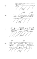
図2は、ウエハ処理装置35の化学的気相堆積(CVD)プロセスチャンバ36の断面略図を示す。CVDプロセスチャンバ36は、本明細書に説明する実施の形態に従って有機ケイ酸塩層を堆積するために使用されることができる。そのようなCVDプロセスチャンバ36の例は、米国カリフォルニア州サンタクララのアプライドマテリアルズ社より入手可能なDXZチャンバである。
【0017】
CVDプロセスチャンバ36は、通常、電源及び真空ポンプ等の他のハードウェア構成要素と共に、ガスパネル130、制御ユニット110を備えている。CVDプロセスチャンバ36の詳細は、1998年12月14日出願の米国特許出願第09/211,998号、発明の名称「高温度化学的気相堆積チャンバ」に記載されている。CVDプロセスチャンバ36の顕著な特徴を以下、簡潔に説明する。
【0018】
CVDプロセスチャンバ36は、一般的に、半導体ウエハ190等の基板を支持するために使用される支持ペデスタル150を格納している。このペデスタル150は、通常、変位機構(図示せず)を使用してチャンバ36内を上下方向に移動できる。特定のプロセスによっては、層堆積に先立ってウエハ190を所望温度まで加熱することができる。例えば、ウエハ支持ペデスタル150は、埋込まれたヒータ要素170によって加熱される。ペデスタル150は、AC電源106からヒータ要素170へ電流を印加することによって抵抗加熱してもよい。同様に、ウエハ190はペデスタル150によって加熱される。熱電対のような温度センサ172もウエハ支持ペデスタル150内に埋込まれ、従来の様式でペデスタル150の温度を監視する。測定された温度は、加熱要素170の電源16を制御するフィードバックループで使用され、それによりウエハ温度を特有なプロセス用途にとって好適な所望温度に維持したり、制御することができる。ペデスタル150はプラズマを使用して、又は放射熱(図示せず)によって任意に加熱される。
【0019】
真空ポンプ102を用いて、プロセスチャンバ36を排気するとともに、チャンバ36内で適正なガス流量と圧力とを維持する。シャワーヘッド120は、それを通してプロセスガスがチャンバ36内へ導入されるが、ウエハ支持ペデスタル150の上方に配置される。シャワーヘッド120は、プロセスシーケンスの異なるステップで使用される種々のガスを制御し供給するガスパネル130へ接続される。
【0020】
シャワーヘッド120及びウエハ支持ペデスタル150は、一対の間隔を置いた電極も形成する。電界がこれらの電極間に生成されたときに、チャンバ36内へ導入されたプロセスガスは点火されて、プラズマとなる。通常、電界は、ウエハ支持ペデスタル150をRF電力のソース(図示せず)へ整合回路網(図示せず)を介して接続することによって生成される。代替として、RF電源及び整合回路網はシャワーヘッド120へ結合してもよいし、シャワーヘッド120及びウエハ支持ペデスタル150の両方へ結合してもよい。
【0021】
プラズマ強化化学的気相堆積(PECVD)技術は、基板表面近くの反応ゾーンへ電界を印加することによって反応性ガスの励起及び/又は解離を促進し、反応性核種のプラズマを生成する。プラズマ中の核種は反応性があり、これにより生成の化学反応に必要なエネルギーを低減し、結局このPECVDプロセスのために要する温度を低下させる。
【0022】
少なくとも1つの実施の形態では、有機ケイ酸塩層堆積は、フェニルメチルシラン等のフェニル基を有するシラン化合物のプラズマ強化酸化によって成し遂げられる。フェニル基を有するシラン化合物は、ガスパネル130の制御下で調節された流量のガスとしてプロセスチャンバ36内へ導入される。
【0023】
ガスパネル130を通るガス流量の適正な制御及び調節は、質量流量コントローラ(図示せず)及びコンピュータ(図示せず)によって遂行される。シャワーヘッド120は、ガスパネル130からのプロセスガスを、プロセスチャンバ100内へ均一に導入して分配できるようにする。
【0024】
図1を参照すると、CVDプロセスチャンバ36は、マイクロプロセッサコントローラ54によって制御される。マイクロプロセッサコントローラ54は、工業用環境において種々のチャンバ及びサブプロセッサを制御するために使用できるいずれの形態の汎用コンピュータプロセッサ(CPU)の1つであってもよい。コンピュータは、随時書込み読出メモリ、読出専用メモリ、フロッピディスクドライブ、ハードディスク、又はいずれか他の形態のデジタル記憶装置など、局所の又は遠隔の、いずれか好適なメモリを使用してよい。種々の支援回路が、従来の様式でプロセッサを支援するためにCPUへ結合できる。必要に応じてソフトウエアルーチンを、メモリ内に格納でき、あるいは、遠隔地に配置される第2CPUによって実行できる。
【0025】
ソフトウエアルーチンは、基板がペデスタル上に配置された後に実行される。ソフトウエアルーチンは、実行される際に、汎用コンピュータをチャンバ動作を制御する特定プロセスコンピュータに変換し、それによりチャンバプロセスが遂行される。代替として、本発明のプロセスは、ハードウエアで、特定用途向け集積回路又は他の種類のハードウエア実施手段として、又は、ソフトウエア又はハードウエアの組合せで遂行されることができる。
【0026】
有機ケイ酸塩層の堆積
1つの実施の形態で、有機ケイ酸塩層は、フェニル基を有するシラン化合物を含む混合ガスへ電界を印加することによって形成される。フェニル基を有するシラン化合物は、一般的化学式SiCaObHcを有し、ここでaの範囲は6と30の間であり、bの範囲は0と3の間であり、そして、cの範囲は8と30の間である。例えば、フェニルシラン(SiC6H 8 )、フェニルメチルシラン(SiC7H 10 )、フェニルエチルシラン(SiC8H 12 )、フェニルメチルエチルシラン(SiC9H 14 )、フェニルメトキシシラン(SiC7OH 10 )、フェニルエトキシシラン(SiC8OH 12 )、フェニルメチルエトキシシラン(SiC9OH 14 )、フェニルメトキシエトキシシラン(SiC9O2H 14 )が、フェニル基を有するシラン化合物として使用できる。
【0027】
混合ガスは任意に酸化性ガスを含むことができる。例えば、酸素(O2)、オゾン(O3)亜酸化窒素(N2O)、一酸化炭素(CO)、二酸化炭素(CO2)、窒素(N2)、又は、その組合せが、酸化性ガスとして使用できる。
【0028】
一般に、以下の堆積プロセスパラメータが、図2に示すものと類似するCVDプロセスチャンバを使用して有機ケイ酸塩層を形成するために使用できる。プロセスパラメータは、約100℃から約400℃のウエハ温度、約1Torrから10Torrのチャンバ圧力、約400mgmから約1000mgmのフェニル基を有するシラン化合物のガス流量、約1sccmから約500sccmの酸化性ガスの流量、及び、約50ワットから約500ワットのRF電力の範囲に及ぶ。上記プロセスパラメータは、アプライドマテリアルズ社より入手可能な堆積チャンバ内で200mm(ミリメートル)基板上に実施される場合、約1000Å/分から約4000Å/分の範囲での有機ケイ酸塩層に対する堆積レートを提供する。
【0029】
他の堆積チャンバは本発明の範囲内であり、上に記載のパラメータは、有機ケイ酸塩層を形成するために使用される特定の堆積チャンバによって変えてもよい。例えば、他の堆積チャンバ容積を大きくしたり小さくしたりすれば、アプライドマテリアルズ社より入手可能な堆積チャンバに対して記載されたものより大きい又は小さいガス流量を必要とするのであり、また300mm基板を収容するよう構成してもよい。
【0030】
有機ケイ酸塩のアズデポ(as depo.)層は、約3.0未満の比誘電率を有し、集積回路に絶縁材料として使用に好適なものにする。有機ケイ酸塩層の比誘電率は調整可能であり、反応温度に関して約2.0〜約3.0で変化できる。詳細には、温度が高くなれば、アズデポ層の比誘電率が減少する。
【0031】
有機ケイ酸塩層の比誘電率は、層形成中の混合ガスの組成の関数として調整することもできる。混合ガス中の炭素(C)濃度が増大えると、堆積されたままの有機ケイ酸塩層のC含有量が増大し、その比誘電率を減少させる。
【0032】
有機ケイ酸塩層は、約250nm未満の波長で約0.1から約0.7の範囲で調整可能な光吸収係数を持つ。光吸収係数は、反応温度の関数として調整可能である。詳細には、温度が高まると、堆積したままの層の光吸収係数が大きくなる。
【0033】
集積回路製造プロセス
A. 有機ケイ酸塩反射防止皮膜(ARC)
図3a〜3eは、フルオロ−有機ケイ酸塩層をハードマスクとして組込む集積回路製造シーケンスの異なる段階での基板200の断面略図を示す。一般に、基板200は、その上で処理が遂行される何らかのワークピースを指し、基板構造250は、基板200上に形成される他の材料層と一緒に基板を包括的に表わすために使用される。処理の特定の段階に従って、基板200は、シリコン基板、又は基板上に形成された他の材料層に対応させてもよい。例えば、図3aは、基板上常套的に形成された材料層202を有する基板構造250の断面図を示す。材料層202は、酸化物(例えば、二酸化ケイ素)であってもよい。一般に、基板200は、シリコン、シリサイド、メタル、又は他の材料を含んでよい。図3aは、基板200がその上に形成された二酸化ケイ素層を有するシリコンである1つの実施の形態を示す。
【0034】
図3bは、図3aの基板構造250上に形成された有機ケイ酸塩層204を図示する。有機ケイ酸塩層204は、先に記載のプロセスパラメータに従い基板構造250上に形成される。有機ケイ酸塩層の厚さは、処理の特定の段階に依存して変更可能である。通常、有機ケイ酸塩層は、約400Åから約700Åの厚さまで堆積される。
【0035】
エネルギー感応性レジスト材料層208が、有機ケイ酸塩層204上に形成される。エネルギー感応性レジスト材料層208は、基板上へ約4,000Åから約10,000Åの範囲内の厚さまでスピン塗布できる。大部分のエネルギー感応性レジスト材料は、約450nm(ナノメートル)未満の波長の紫外(UV)放射線に対して感応性である。深紫外(DUV)レジスト材料は、約245nm未満の波長のUV放射線に対して感応性である。
【0036】
製造シーケンスで使用されるエネルギー感応性レジスト材料のエッチング化学薬品に依存して、中間層206が、エネルギー感応性レジスト材料の層208に先立って有機ケイ酸塩層204上に形成される。エネルギー感応性レジスト材料208及び有機ケイ酸塩層204が同じ化学薬品エッチャントを使用してエッチングできる場合、中間層206は、有機ケイ酸塩層204のためのマスクとして機能する。中間層206は、常套的に有機ケイ酸塩層204上に形成される。中間層206は、酸化物、窒化物、酸窒化ケイ素、アモルファスシリコン、又は他の好適な材料であってもよい。
【0037】
パターンの画像は、エネルギー感応性レジスト材料208をDUV放射線へマスク210を経て暴露することによってそのようなエネルギー感応性レジスト材料層208へ導入される。エネルギー感応性レジスト材料層208へ導入されたパターンの画像は、適切な現像剤中で現像され、図3cに示すように、その中にパターンを形成する。
【0038】
図3dを参照すると、エネルギー感応性レジスト材料208内に形成されたパターンは、有機ケイ酸塩層204の中に転写される。パターンは、エネルギー感応性レジスト材料208をマスクとして使用して、有機ケイ酸塩層204の中に転写される。パターンは、適切な化学薬品エッチャントを使用して、有機ケイ酸塩層204の中に転写される。例えば、フルオロメタン(CF4)、フルオロエタン(C2F6)、及びフルオロブテン(C4H8)等のフルオロカーボン化合物が、有機ケイ酸塩層204を使用して化学的にエッチングすることができる。
【0039】
代替として、中間層206がある場合、エネルギー感応性レジスト材料208内に形成されたパターンは、エネルギー感応性レジスト材料208をマスクとして使用して、最初に中間層206の中に転写される。その後に、パターンは、中間層206をマスクとして使用して、有機ケイ酸塩層204の中に転写される。パターンは、適切な化学薬品エッチャントを使用して、中間層206と有機ケイ酸塩層204の両方の中に転写される。
【0040】
図3eは、有機ケイ酸塩層をハードマスクとして使用して、有機ケイ酸塩層204に形成されたパターンの二酸化ケイ素層202の中の転写によって集積回路製造シーケンスの完結を図示する。
【0041】
二酸化ケイ素層202がパターニングされた後に、有機ケイ酸塩層204は、任意に好適な化学薬品エッチャントでエッチングすることによって基板200から取り除くことができる。
B. 有機ケイ酸塩層を組込むダマシン構造
図4a〜4dは、有機ケイ酸塩層を組込むダマシン構造製造シーケンスの異なる段階での基板300の断面略図を示す。ダマシン構造は、通常、集積回路上にメタル配線を形成するために使用される。処理の特定の段階に従って、基板300は、シリコン基板、又は、基板300上に形成された他の材料層に対応させてもよい。例えば、図4aは、その上に形成された第1誘電体層302を有する基板300の断面図を示す。第1誘電体層302は、酸化物(例えば、二酸化ケイ素、フルオロケイ酸塩ガラス)であってもよい。一般に、基板300は、シリコン、シリサイド、メタル、又は他の材料の層を含んでよい。
【0042】
図4aは、基板300が、上に形成されたフルオロケイ酸塩ガラス層を有するシリコンである1つの実施の形態を示す。第1誘電体層302の厚さは、製造される構造の大きさにもよるが、約5,000Å〜約10,000Åである。
【0043】
有機ケイ酸塩層304は、第1誘電体層302上に形成される。有機ケイ酸塩層304は、先に記載のプロセスパラメータに従い第1誘電体層302上に形成される。有機ケイ酸塩層304は、約3.0未満の比誘電率を有し、それによりダマシン構造に形成されることになるメタル配線間の容量結合を阻止、つまり最小化する。有機ケイ酸塩層に対する比誘電率は調整可能であり、層形成中の反応温度だけでなく混合ガスの組成の関数として所望範囲で変えることができる。
【0044】
有機ケイ酸塩層304の厚さは、処理の特定段階に依存して変更可能である。通常、有機ケイ酸塩層304の厚さは約200Åから約1000Åである。
【0045】
図4bを参照すると、有機ケイ酸塩層304は、パターニングされてエッチングされ、コンタクト/バイア開口部306を形成し、コンタクト/バイアが形成されることになる領域で第1誘電体層302を露出させる。有機ケイ酸塩層304は、従来のリソグラフィを使用してパターニングされ、フルオロメタン(CF4)、フルオロエタン(C2F6)、及びフルオロブテン(C4H8)等のフルオロカーボン化合物を使用してエッチングされる。
【0046】
有機ケイ酸塩層304がパターニングされた後で、第2誘電体層308が有機ケイ酸塩層304を覆って堆積される。第2誘電体層308は、酸化物(例えば、二酸化ケイ素、フルオロケイ酸塩ガラス)であってもよい。第2誘電体層308の厚さは、約5,000Å〜約10,000Åである。
【0047】
第2誘電体層308は、次に、図4cに図示するように、好ましくは従来のリソグラフィプロセスを使用してパターニングされ、配線の線310を形成する。第2誘電体層308内に形成された配線310は、有機ケイ酸塩層304内のコンタクト/バイア開口部306を覆って配置される。その後に、配線310及びコンタクト/バイア306の両方が、反応性イオンエッチング又は他の異方性エッチング技術を使用してエッチングされる。
【0048】
図4dを参照すると、配線310及びコンタクト/バイア306は、アルミニウム、銅、タングステン、又は、その組合せ等の導電性材料314で充填される。通常は、低い固有抵抗(固有抵抗が約1.7μΩ−cm)のゆえに、銅を使用して、配線310及びコンタクト/バイア306を充填する。導電性材料314は、化学的気相堆積、物理気相堆積、電気メッキ、又は、その組合せを使用して堆積され、ダマシン構造を形成する。好ましくは、タンタル、窒化タンタル、又は他の好適なバリア材料のようなバリア層316が、最初に、配線310及びコンタクト/バイア306の側壁上に従形して堆積され、周囲の誘電体層302、308だけでなく有機ケイ酸塩層304内へのメタルの泳動を阻止する。
【0049】
本発明の教示を組込む幾つかの好ましい実施の形態を示して、詳細に説明したが、この技術に精通した者は、これらの教示を依然として組込む多くの他の変更された実施の形態を容易に考案することができよう。
【図面の簡単な説明】
【図1】本明細書に説明した実施の形態の実施のために使用できる装置の略図である。
【図2】化学的気相堆積(CVD)チャンバの断面略図である。
【図3】a〜eは、有機ケイ酸塩層を反射防止皮膜(ARC)として組込む集積回路製造の異なる段階での基板の断面略図である。
【図4】a〜dは、有機ケイ酸塩層をダマシン構造内に組込む集積回路製造の異なる段階でのそのような構造の断面略図を描である。
【符号の説明】
16,106…電源、35…ウエハ処理装置、36,100…プロセスチャンバ、46…ロードロックチャンバ、50…搬送チャンバ、51…搬送ロボット、54…マイクロプロセッサコントローラ、102…真空ポンプ、110…制御ユニット、120…シャワーヘッド、130…ガスパネル、150…支持ペデスタル、170…ヒータ要素、172…温度センサ、190…ウエハ、200,300…基板、202,304…材料層、206…中間層、208…エネルギー感応性レジスト材料、210…マスク、250…基板構造、302,308…誘電体層、306…バイア、310…配線、314…導電性材料、316…バリア層。[0001]
BACKGROUND OF THE INVENTION
The present invention relates to an organosilicate layer, its use in integrated circuit manufacture, and a method for forming an organosilicate layer.
[0002]
[Prior art]
Integrated circuits have evolved into complex devices that can contain millions of components (eg, transistors, capacitors, and resistors) on a single chip. The evolution of chip design constantly requires faster circuits and greater circuit density. The demand for higher circuit density is accompanied by a reduction in the dimensions of integrated circuit components.
[0003]
As the dimensions of integrated circuit components shrink (eg, sub-micron dimensions), the materials used to manufacture such components contribute to the electrical performance of the component. For example, low resistivity metal wiring (eg, copper and aluminum) provides a conductive path between components on an integrated circuit. Usually, metal wirings are electrically isolated from each other by an insulating material. If the distance between adjacent metal lines and / or the thickness of the insulating material has sub-micron dimensions, capacitive coupling can occur between such lines. Capacitive coupling between adjacent metal lines can cause crosstalk and / or resistance and capacitance (RC) delay, which degrades the overall performance of the integrated circuit. In order to prevent capacitive coupling between adjacent metal wirings, an insulating material having a low dielectric constant (low k) (for example, a dielectric constant of less than about 4.5) is required.
[0004]
[Problems to be solved by the invention]
The demand for higher integrated circuit density also imposes a demand on process sequences used in integrated circuit manufacturing. For example, in a process sequence using conventional lithographic techniques, a layer of energy sensitive resist is formed over a stack of material layers on a substrate. Many of these base material layers are reflective to ultraviolet rays. Such reflections distort the dimensions of features such as lines and vias formed in the energy sensitive resist material.
[0005]
One technique that has been proposed to minimize reflection from the underlying material layer uses an anti-reflective coating (ARC). The ARC is formed over the reflective material layer prior to resist pattern formation. ARC suppresses reflections from the underlying material layer during resist writing and provides accurate pattern replication within the layer of energy sensitive resist.
[0006]
Accordingly, there is a need in the art for a low dielectric constant material suitable for integrated circuit manufacture. Particularly desirable would be a low dielectric constant material that is also an ARC.
[0007]
[Means for Solving the Problems]
A method is provided for forming an organosilicate layer for use in integrated circuit manufacture. In one embodiment, the organosilicate layer is formed by applying an electric field to a mixed gas containing a silane compound containing a phenyl group. The mixed gas may optionally contain an oxidizing gas.
[0008]
The organosilicate layer is compatible with the integrated circuit manufacturing process. In one integrated circuit manufacturing process, the organosilicate layer is used as an anti-reflective coating (ARC) for DUV lithography. A preferred process sequence for such an embodiment includes forming an organosilicate layer on the substrate. The organosilicate layer has a refractive index in the range of about 1.20 to about 1.70 and a light absorption coefficient in the range of about 0.1 to about 0.7 at a wavelength of less than about 250 nm. The refractive index (n) and light absorption coefficient (κ) of the organosilicate layer can be adjusted, both of which vary to the desired range as a function of the composition of the gas used during layer formation as well as the deposition temperature Can do. After the organosilicate layer is formed on the substrate, a layer of energy sensitive resist material is formed thereon. A pattern is formed in the energy sensitive resist at a wavelength of less than about 250 nm. Thereafter, the pattern formed in the energy sensitive resist material is transferred into the organosilicate layer. After the organosilicate layer is patterned, such a pattern is optionally transferred into the substrate using the organosilicate ARC layer as a hard mask.
[0009]
In another integrated circuit manufacturing process, the organosilicate layer is incorporated into a damascene structure. For such an embodiment, a preferred process sequence includes depositing a first dielectric layer on the substrate. Next, an organosilicate layer is formed on the first dielectric layer. The organosilicate layer is then patterned and etched to form contacts / vias therein. After the organosilicate layer is patterned and etched, a second dielectric layer is deposited over it. Next, the second dielectric layer is patterned and etched to form wiring therein. Wiring formed in the second dielectric layer is placed over the contacts / vias formed in the organosilicate layer. After the wiring is formed, the contacts / vias formed in the organosilicate layer are etched through the first dielectric layer to the substrate surface. The damascene structure is then completed by filling the wiring and contacts / vias with a conductive material.
[0010]
DETAILED DESCRIPTION OF THE INVENTION
The teachings of the present invention can be readily understood by considering the following detailed description in conjunction with the accompanying drawings, in which:
[0011]
FIG. 1 schematically illustrates a
[0012]
The details of the
[0013]
The
[0014]
A substrate (not shown) is loaded into the
[0015]
[0016]
FIG. 2 shows a schematic cross-sectional view of a chemical vapor deposition (CVD)
[0017]
The
[0018]
The
[0019]
The
[0020]
The
[0021]
Plasma enhanced chemical vapor deposition (PECVD) technology promotes the excitation and / or dissociation of reactive gases by applying an electric field to a reaction zone near the substrate surface to generate a reactive nuclide plasma. The nuclides in the plasma are reactive, thereby reducing the energy required for the chemical reaction of production and eventually lowering the temperature required for this PECVD process.
[0022]
In at least one embodiment, organosilicate layer deposition is accomplished by plasma enhanced oxidation of a silane compound having a phenyl group, such as phenylmethylsilane. The silane compound having a phenyl group is introduced into the
[0023]
Proper control and adjustment of gas flow through the
[0024]
Referring to FIG. 1, the
[0025]
The software routine is executed after the substrate is placed on the pedestal. When executed, the software routine converts the general purpose computer into a specific process computer that controls chamber operation, whereby the chamber process is performed. Alternatively, the process of the present invention can be performed in hardware, as an application specific integrated circuit or other type of hardware implementation, or in software or a combination of hardware.
[0026]
Deposition of organosilicate layer In one embodiment, the organosilicate layer is formed by applying an electric field to a gas mixture comprising a silane compound having a phenyl group. Silane compound having a phenyl group and have general formula SiCaObHc, where is between the range of a is 6 to 30, the range of b is between 0 and 3, and the range of c is 8 and Between 30. For example, phenylsilane (SiC 6 H 8 ), phenylmethylsilane (SiC 7 H 10 ), phenylethylsilane (SiC 8 H 12 ), phenylmethylethylsilane (SiC 9 H 14 ), phenylmethoxysilane (SiC 7 OH 10) ), Phenylethoxysilane (SiC 8 OH 12 ), phenylmethylethoxysilane (SiC 9 OH 14 ), and phenylmethoxyethoxysilane (SiC 9 O 2 H 14 ) can be used as the silane compound having a phenyl group.
[0027]
The mixed gas can optionally include an oxidizing gas. For example, oxygen (O 2 ), ozone (O 3 ), nitrous oxide (N 2 O), carbon monoxide (CO), carbon dioxide (CO 2 ), nitrogen (N 2 ), or a combination thereof can be oxidized. Can be used as a gas.
[0028]
In general, the following deposition process parameters can be used to form an organosilicate layer using a CVD process chamber similar to that shown in FIG. Process parameters include wafer temperature of about 100 ° C. to about 400 ° C., chamber pressure of about 1 Torr to 10 Torr, gas flow rate of silane compounds having phenyl groups of about 400 mgm to about 1000 mgm, flow rate of oxidizing gas of about 1 sccm to about 500 sccm. And ranging from about 50 watts to about 500 watts of RF power. The above process parameters are for deposition rates for organosilicate layers in the range of about 1000 liters / minute to about 4000 liters / minute when performed on 200 mm (millimeter) substrates in a deposition chamber available from Applied Materials. provide.
[0029]
Other deposition chambers are within the scope of the present invention, and the parameters described above may vary depending on the particular deposition chamber used to form the organosilicate layer. For example, increasing or decreasing the volume of other deposition chambers may require a gas flow rate that is greater or less than that described for deposition chambers available from Applied Materials, and a 300 mm substrate. You may comprise so that it may accommodate.
[0030]
The organosilicate as depo. Layer has a dielectric constant of less than about 3.0, making it suitable for use as an insulating material in integrated circuits. The relative dielectric constant of the organosilicate layer is adjustable and can vary from about 2.0 to about 3.0 with respect to the reaction temperature. Specifically, as the temperature increases, the relative dielectric constant of the as-deposited layer decreases.
[0031]
The dielectric constant of the organosilicate layer can also be adjusted as a function of the composition of the mixed gas during layer formation. As the carbon (C) concentration in the gas mixture increases, the C content of the as-deposited organosilicate layer increases and decreases its dielectric constant.
[0032]
The organosilicate layer has a light absorption coefficient that is adjustable from about 0.1 to about 0.7 at a wavelength of less than about 250 nm. The light absorption coefficient can be adjusted as a function of the reaction temperature. Specifically, as the temperature increases, the light absorption coefficient of the as-deposited layer increases.
[0033]
Integrated circuit manufacturing process A.1. Organosilicate antireflection coating (ARC)
3a-3e show schematic cross-sectional views of the
[0034]
FIG. 3b illustrates an
[0035]
An energy sensitive resist
[0036]
Depending on the etching chemistry of the energy sensitive resist material used in the manufacturing sequence, an
[0037]
An image of the pattern is introduced into such an energy sensitive resist
[0038]
With reference to FIG. 3 d, the pattern formed in the energy sensitive resist
[0039]
Alternatively, if there is an
[0040]
FIG. 3e illustrates the completion of the integrated circuit manufacturing sequence by transfer in the
[0041]
After the
B. Damascene Structures Incorporating Organosilicate Layers FIGS. 4a-4d show cross-sectional schematics of a
[0042]
FIG. 4a shows one embodiment where the
[0043]
An
[0044]
The thickness of the
[0045]
Referring to FIG. 4b, the
[0046]
After the
[0047]
The
[0048]
Referring to FIG. 4d, the
[0049]
While several preferred embodiments incorporating the teachings of the present invention have been shown and described in detail, those skilled in the art will readily appreciate many other modified embodiments that still incorporate these teachings. Can be devised.
[Brief description of the drawings]
FIG. 1 is a schematic illustration of an apparatus that can be used to implement the embodiments described herein.
FIG. 2 is a schematic cross-sectional view of a chemical vapor deposition (CVD) chamber.
FIGS. 3a-e are schematic cross-sectional views of a substrate at different stages of integrated circuit fabrication incorporating an organosilicate layer as an anti-reflective coating (ARC). FIGS.
FIGS. 4a-d depict schematic cross-sectional views of such structures at different stages of integrated circuit fabrication incorporating an organosilicate layer into a damascene structure.
[Explanation of symbols]
DESCRIPTION OF SYMBOLS 16,106 ... Power supply, 35 ... Wafer processing apparatus, 36, 100 ... Process chamber, 46 ... Load lock chamber, 50 ... Transfer chamber, 51 ... Transfer robot, 54 ... Microprocessor controller, 102 ... Vacuum pump, 110 ... Control unit , 120 ... Shower head, 130 ... Gas panel, 150 ... Support pedestal, 170 ... Heater element, 172 ... Temperature sensor, 190 ... Wafer, 200, 300 ... Substrate, 202, 304 ... Material layer, 206 ... Intermediate layer, 208 ... Energy sensitive resist material, 210 ... mask, 250 ... substrate structure, 302, 308 ... dielectric layer, 306 ... via, 310 ... wiring, 314 ... conductive material, 316 ... barrier layer.
Claims (47)
基板を堆積チャンバ内に配置するステップと、
混合ガスを堆積チャンバへ供給するステップであって、当該混合ガスはアルキル基及びSi−H結合を有するフェニル基を有するシラン化合物を有し、及び当該フェニル基を有するシラン化合物は400mgm〜1000mgmの流量で堆積チャンバへ供給されるステップと、
堆積チャンバ内で混合ガスに電界を印加して、有機ケイ酸塩層を基板上に形成するステップと
を有し、
前記フェニル基を有するシラン化合物は、フェニルエチルシラン(SiC8H12)と、フェニルメチルエチルシラン(SiC9H14)と、フェニルメトキシシラン(SiC7OH10)と、フェニルエトキシシラン(SiC8OH12)と、フェニルメチルエトキシシラン(SiC9OH14)と、フェニルメトキシエトキシシラン(SiC9O2H14)と、これらの混合物とから成る群より選択される方法。A method for depositing a thin film comprising:
Placing the substrate in a deposition chamber;
Supplying a mixed gas to the deposition chamber, wherein the mixed gas has a silane compound having a phenyl group having an alkyl group and a Si-H bond, and the silane compound having the phenyl group has a flow rate of 400 mgm to 1000 mgm. Supplying to the deposition chamber at
Applying an electric field to the gas mixture in a deposition chamber to form an organosilicate layer on the substrate;
The silane compound having a phenyl group includes phenylethylsilane (SiC 8 H 12 ), phenylmethylethylsilane (SiC 9 H 14 ), phenylmethoxysilane (SiC 7 OH 10 ), and phenylethoxysilane (SiC 8 OH). 12 ), phenylmethylethoxysilane (SiC 9 OH 14 ), phenylmethoxyethoxy silane (SiC 9 O 2 H 14 ), and mixtures thereof.
基板を堆積チャンバ内へ配置するステップと、
混合ガスを堆積チャンバへ供給するステップであって、当該混合ガスはアルキル基及びSi−H結合を有するフェニル基を有するシラン化合物を有し、及び当該フェニル基を有するシラン化合物は400mgm〜1000mgmの流量で堆積チャンバへ供給されるステップと、
堆積チャンバ内で混合ガスに電界を印加して、有機ケイ酸塩層を基板上に形成するステップと
を有し、
前記混合ガスは、フェニルエチルシラン(SiC8H12)と、フェニルメチルエチルシラン(SiC9H14)と、フェニルメトキシシラン(SiC7OH10)と、フェニルエトキシシラン(SiC8OH12)と、フェニルメチルエトキシシラン(SiC9OH14)と、フェニルメトキシエトキシシラン(SiC9O2H14)と、これらの混合物とから成る群より選択されたフェニル基を有するシラン化合物を含む方法。A method of forming an organosilicate layer on a substrate, comprising:
Placing the substrate in a deposition chamber;
Supplying a mixed gas to the deposition chamber, wherein the mixed gas has a silane compound having a phenyl group having an alkyl group and a Si-H bond, and the silane compound having the phenyl group has a flow rate of 400 mgm to 1000 mgm. Supplying to the deposition chamber at
Applying an electric field to the gas mixture in a deposition chamber to form an organosilicate layer on the substrate;
The mixed gas includes phenylethylsilane (SiC 8 H 12 ), phenylmethylethylsilane (SiC 9 H 14 ), phenylmethoxysilane (SiC 7 OH 10 ), phenylethoxysilane (SiC 8 OH 12 ), A method comprising a silane compound having a phenyl group selected from the group consisting of phenylmethylethoxysilane (SiC 9 OH 14 ), phenylmethoxyethoxysilane (SiC 9 O 2 H 14 ), and a mixture thereof.
アルキル基及びSi−H結合を有するフェニル基を有するシラン化合物を有する混合ガスに電界を印加して、有機ケイ酸塩層を基板上に形成するステップと、
有機ケイ酸塩層の少なくとも1つの区域にパターンを形成するステップと、
有機ケイ酸塩層をマスクとして使用して、有機ケイ酸塩層の少なくとも1つの区域に形成されたパターンを、基板内へ転写するステップと
を有し、
前記フェニル基を有するシラン化合物は、フェニルエチルシラン(SiC8H12)と、フェニルメチルエチルシラン(SiC9H14)と、フェニルメトキシシラン(SiC7OH10)と、フェニルエトキシシラン(SiC8OH12)と、フェニルメチルエトキシシラン(SiC9OH14)と、フェニルメトキシエトキシシラン(SiC9O2H14)と、これらの混合物とから成る群より選択される方法。A method of forming a device comprising:
Applying an electric field to a mixed gas containing a silane compound having an alkyl group and a phenyl group having a Si-H bond to form an organosilicate layer on the substrate;
Forming a pattern in at least one area of the organosilicate layer;
Transferring the pattern formed in at least one area of the organosilicate layer into the substrate using the organosilicate layer as a mask;
The silane compound having a phenyl group includes phenylethylsilane (SiC 8 H 12 ), phenylmethylethylsilane (SiC 9 H 14 ), phenylmethoxysilane (SiC 7 OH 10 ), and phenylethoxysilane (SiC 8 OH). 12 ), phenylmethylethoxysilane (SiC 9 OH 14 ), phenylmethoxyethoxy silane (SiC 9 O 2 H 14 ), and mixtures thereof.
エネルギー感応性レジスト材料の層を、有機ケイ酸塩層上に形成するステップと、
エネルギー感応性レジスト材料を、パターニングを有する放射に曝露して、エネルギー感応性レジスト材料の層にパターン画像を導入するステップと、
エネルギー感応性レジスト材料の層に導入されたパターンの画像を現像するステップと、
有機ケイ酸塩層の中にパターンを転写するステップと
を有する請求項17に記載の方法。Forming a pattern in at least one area of the organosilicate layer,
Forming a layer of energy sensitive resist material on the organosilicate layer;
Exposing the energy sensitive resist material to radiation having patterning to introduce a pattern image into the layer of energy sensitive resist material;
Developing an image of the pattern introduced into the layer of energy sensitive resist material;
And transferring the pattern into the organosilicate layer.
エネルギー感応性レジスト材料の層に現像されたパターンの画像を中間層の中に転写するステップと
を更に有する請求項20に記載の方法。Forming an intermediate layer on the organosilicate layer before forming the layer of energy sensitive resist material, introducing an image of the pattern therein, and developing the pattern;
21. The method of claim 20, further comprising the step of transferring an image of the developed pattern onto the layer of energy sensitive resist material into the intermediate layer.
第1誘電体層を基板上に形成するステップと、
アルキル基及びSi−H結合を有するフェニル基を有するシラン化合物を有する混合ガスに電界を印加することにより、有機ケイ酸塩層を第1誘電体層上に形成するステップと、
有機ケイ酸塩層をパターニングし、その中にコンタクト/バイアを形成するステップと、
第2誘電体層を、パターニングされた有機ケイ酸塩層上に形成するステップと、
第2誘電体層をパターニングし、そこに、有機ケイ酸塩層に形成された該コンタクト/バイヤの上に配置される配線を形成するステップと、
第1誘電体層をエッチングし、そこにコンタクト/バイアを形成するステップと、
該コンタクト/バイア及び該配線を導電性材料で充填するステップと
を有し、
前記フェニル基を有するシラン化合物は、フェニルエチルシラン(SiC8H12)と、フェニルメチルエチルシラン(SiC9H14)と、フェニルメトキシシラン(SiC7OH10)と、フェニルエトキシシラン(SiC8OH12)と、フェニルメチルエトキシシラン(SiC9OH14)と、フェニルメトキシエトキシシラン(SiC9O2H14)と、これらの混合物とから成る群より選択される方法。A method of manufacturing a damascene structure,
Forming a first dielectric layer on the substrate;
Forming an organosilicate layer on the first dielectric layer by applying an electric field to a mixed gas comprising a silane compound having an alkyl group and a phenyl group having a Si-H bond;
Patterning an organosilicate layer and forming contacts / vias therein;
Forming a second dielectric layer on the patterned organosilicate layer;
Patterning a second dielectric layer and forming therein wiring disposed over the contacts / buyer formed in the organosilicate layer;
Etching the first dielectric layer to form contacts / vias therein;
Filling the contact / via and the wiring with a conductive material;
The silane compound having a phenyl group includes phenylethylsilane (SiC 8 H 12 ), phenylmethylethylsilane (SiC 9 H 14 ), phenylmethoxysilane (SiC 7 OH 10 ), and phenylethoxysilane (SiC 8 OH). 12 ), phenylmethylethoxysilane (SiC 9 OH 14 ), phenylmethoxyethoxy silane (SiC 9 O 2 H 14 ), and mixtures thereof.
Applications Claiming Priority (2)
| Application Number | Priority Date | Filing Date | Title |
|---|---|---|---|
| US09/638803 | 2000-08-12 | ||
| US09/638,803 US6573196B1 (en) | 2000-08-12 | 2000-08-12 | Method of depositing organosilicate layers |
Publications (3)
| Publication Number | Publication Date |
|---|---|
| JP2002164347A JP2002164347A (en) | 2002-06-07 |
| JP2002164347A5 JP2002164347A5 (en) | 2011-08-18 |
| JP5075310B2 true JP5075310B2 (en) | 2012-11-21 |
Family
ID=24561503
Family Applications (1)
| Application Number | Title | Priority Date | Filing Date |
|---|---|---|---|
| JP2001245703A Expired - Fee Related JP5075310B2 (en) | 2000-08-12 | 2001-08-13 | Method for depositing an organosilicate layer |
Country Status (5)
| Country | Link |
|---|---|
| US (1) | US6573196B1 (en) |
| EP (1) | EP1180554A3 (en) |
| JP (1) | JP5075310B2 (en) |
| KR (1) | KR100857664B1 (en) |
| TW (1) | TW593739B (en) |
Families Citing this family (18)
| Publication number | Priority date | Publication date | Assignee | Title |
|---|---|---|---|---|
| JP4381526B2 (en) * | 1999-10-26 | 2009-12-09 | 東京エレクトロン株式会社 | Plasma etching method |
| US6759327B2 (en) * | 2001-10-09 | 2004-07-06 | Applied Materials Inc. | Method of depositing low k barrier layers |
| US6890850B2 (en) * | 2001-12-14 | 2005-05-10 | Applied Materials, Inc. | Method of depositing dielectric materials in damascene applications |
| US6699784B2 (en) | 2001-12-14 | 2004-03-02 | Applied Materials Inc. | Method for depositing a low k dielectric film (K>3.5) for hard mask application |
| US6838393B2 (en) * | 2001-12-14 | 2005-01-04 | Applied Materials, Inc. | Method for producing semiconductor including forming a layer containing at least silicon carbide and forming a second layer containing at least silicon oxygen carbide |
| US7091137B2 (en) * | 2001-12-14 | 2006-08-15 | Applied Materials | Bi-layer approach for a hermetic low dielectric constant layer for barrier applications |
| US6790788B2 (en) * | 2003-01-13 | 2004-09-14 | Applied Materials Inc. | Method of improving stability in low k barrier layers |
| US7270931B2 (en) | 2003-10-06 | 2007-09-18 | International Business Machines Corporation | Silicon-containing compositions for spin-on ARC/hardmask materials |
| US7229911B2 (en) * | 2004-04-19 | 2007-06-12 | Applied Materials, Inc. | Adhesion improvement for low k dielectrics to conductive materials |
| US20050233555A1 (en) * | 2004-04-19 | 2005-10-20 | Nagarajan Rajagopalan | Adhesion improvement for low k dielectrics to conductive materials |
| US7504727B2 (en) * | 2004-05-14 | 2009-03-17 | International Business Machines Corporation | Semiconductor interconnect structure utilizing a porous dielectric material as an etch stop layer between adjacent non-porous dielectric materials |
| US7271093B2 (en) | 2004-05-24 | 2007-09-18 | Asm Japan K.K. | Low-carbon-doped silicon oxide film and damascene structure using same |
| US20050277302A1 (en) * | 2004-05-28 | 2005-12-15 | Nguyen Son V | Advanced low dielectric constant barrier layers |
| US7229041B2 (en) * | 2004-06-30 | 2007-06-12 | Ohio Central Steel Company | Lifting lid crusher |
| KR100713231B1 (en) * | 2005-12-26 | 2007-05-02 | 제일모직주식회사 | Hardmask composition coated under photoresist and process of producing integrated circuit devices using thereof |
| KR100817933B1 (en) * | 2006-09-28 | 2008-04-15 | 광주과학기술원 | Phenylethylsilane monomers substituted fluoroalkyleneoxy group and polymer therof |
| US11679412B2 (en) | 2016-06-13 | 2023-06-20 | Gvd Corporation | Methods for plasma depositing polymers comprising cyclic siloxanes and related compositions and articles |
| US20170358445A1 (en) | 2016-06-13 | 2017-12-14 | Gvd Corporation | Methods for plasma depositing polymers comprising cyclic siloxanes and related compositions and articles |
Family Cites Families (25)
| Publication number | Priority date | Publication date | Assignee | Title |
|---|---|---|---|---|
| US3962004A (en) * | 1974-11-29 | 1976-06-08 | Rca Corporation | Pattern definition in an organic layer |
| JPH07111957B2 (en) | 1984-03-28 | 1995-11-29 | 圭弘 浜川 | Semiconductor manufacturing method |
| JPS62138529A (en) * | 1985-12-10 | 1987-06-22 | Mitsubishi Electric Corp | Formation of organic silicone thin film |
| US4894352A (en) | 1988-10-26 | 1990-01-16 | Texas Instruments Inc. | Deposition of silicon-containing films using organosilicon compounds and nitrogen trifluoride |
| US5186718A (en) * | 1989-05-19 | 1993-02-16 | Applied Materials, Inc. | Staged-vacuum wafer processing system and method |
| JP2899600B2 (en) * | 1994-01-25 | 1999-06-02 | キヤノン販売 株式会社 | Film formation method |
| US5989998A (en) | 1996-08-29 | 1999-11-23 | Matsushita Electric Industrial Co., Ltd. | Method of forming interlayer insulating film |
| KR100463858B1 (en) * | 1996-08-29 | 2005-02-28 | 마츠시타 덴끼 산교 가부시키가이샤 | Method of forming interlayer insulating film |
| TW353775B (en) * | 1996-11-27 | 1999-03-01 | Tokyo Electron Ltd | Production of semiconductor device |
| JP3173426B2 (en) * | 1997-06-09 | 2001-06-04 | 日本電気株式会社 | Method for manufacturing silica insulating film and method for manufacturing semiconductor device |
| WO1999004911A1 (en) * | 1997-07-28 | 1999-02-04 | Massachusetts Institute Of Technology | Pyrolytic chemical vapor deposition of silicone films |
| US6051321A (en) | 1997-10-24 | 2000-04-18 | Quester Technology, Inc. | Low dielectric constant materials and method |
| JP3726226B2 (en) * | 1998-02-05 | 2005-12-14 | 日本エー・エス・エム株式会社 | Insulating film and manufacturing method thereof |
| US6514880B2 (en) | 1998-02-05 | 2003-02-04 | Asm Japan K.K. | Siloxan polymer film on semiconductor substrate and method for forming same |
| US6432846B1 (en) | 1999-02-02 | 2002-08-13 | Asm Japan K.K. | Silicone polymer insulation film on semiconductor substrate and method for forming the film |
| TW437017B (en) | 1998-02-05 | 2001-05-28 | Asm Japan Kk | Silicone polymer insulation film on semiconductor substrate and method for formation thereof |
| US6383955B1 (en) | 1998-02-05 | 2002-05-07 | Asm Japan K.K. | Silicone polymer insulation film on semiconductor substrate and method for forming the film |
| US6054379A (en) | 1998-02-11 | 2000-04-25 | Applied Materials, Inc. | Method of depositing a low k dielectric with organo silane |
| US6303523B2 (en) | 1998-02-11 | 2001-10-16 | Applied Materials, Inc. | Plasma processes for depositing low dielectric constant films |
| JP3305251B2 (en) * | 1998-02-26 | 2002-07-22 | 松下電器産業株式会社 | Method of forming wiring structure |
| US6068884A (en) | 1998-04-28 | 2000-05-30 | Silcon Valley Group Thermal Systems, Llc | Method of making low κ dielectric inorganic/organic hybrid films |
| US6060132A (en) | 1998-06-15 | 2000-05-09 | Siemens Aktiengesellschaft | High density plasma CVD process for making dielectric anti-reflective coatings |
| US6103456A (en) * | 1998-07-22 | 2000-08-15 | Siemens Aktiengesellschaft | Prevention of photoresist poisoning from dielectric antireflective coating in semiconductor fabrication |
| JP3353743B2 (en) * | 1999-05-18 | 2002-12-03 | 日本電気株式会社 | Semiconductor device and manufacturing method thereof |
| US6436824B1 (en) * | 1999-07-02 | 2002-08-20 | Chartered Semiconductor Manufacturing Ltd. | Low dielectric constant materials for copper damascene |
-
2000
- 2000-08-12 US US09/638,803 patent/US6573196B1/en not_active Expired - Fee Related
-
2001
- 2001-08-06 TW TW090119185A patent/TW593739B/en not_active IP Right Cessation
- 2001-08-06 EP EP01118984A patent/EP1180554A3/en not_active Withdrawn
- 2001-08-10 KR KR1020010048231A patent/KR100857664B1/en not_active IP Right Cessation
- 2001-08-13 JP JP2001245703A patent/JP5075310B2/en not_active Expired - Fee Related
Also Published As
| Publication number | Publication date |
|---|---|
| JP2002164347A (en) | 2002-06-07 |
| TW593739B (en) | 2004-06-21 |
| US6573196B1 (en) | 2003-06-03 |
| EP1180554A2 (en) | 2002-02-20 |
| EP1180554A3 (en) | 2005-02-02 |
| KR100857664B1 (en) | 2008-09-08 |
| KR20020013771A (en) | 2002-02-21 |
Similar Documents
| Publication | Publication Date | Title |
|---|---|---|
| KR100849573B1 (en) | Method of depositing organosilicate layers | |
| JP5116197B2 (en) | Method for forming a device utilizing a silicon carbide layer | |
| US6537733B2 (en) | Method of depositing low dielectric constant silicon carbide layers | |
| US6764958B1 (en) | Method of depositing dielectric films | |
| JP5075310B2 (en) | Method for depositing an organosilicate layer | |
| US6632735B2 (en) | Method of depositing low dielectric constant carbon doped silicon oxide | |
| KR100818953B1 (en) | Method of depositing organosilicate layers | |
| US6777171B2 (en) | Fluorine-containing layers for damascene structures | |
| US20020001778A1 (en) | Photolithography scheme using a silicon containing resist | |
| US6472333B2 (en) | Silicon carbide cap layers for low dielectric constant silicon oxide layers | |
| KR20010112115A (en) | Fluoro-organosilicate layer | |
| JP2002151402A (en) | Silicon nitride anti-reflective coating for 193 nm lithography |
Legal Events
| Date | Code | Title | Description |
|---|---|---|---|
| A621 | Written request for application examination |
Free format text: JAPANESE INTERMEDIATE CODE: A621 Effective date: 20080724 |
|
| RD03 | Notification of appointment of power of attorney |
Free format text: JAPANESE INTERMEDIATE CODE: A7423 Effective date: 20101130 |
|
| RD04 | Notification of resignation of power of attorney |
Free format text: JAPANESE INTERMEDIATE CODE: A7424 Effective date: 20101210 |
|
| A977 | Report on retrieval |
Free format text: JAPANESE INTERMEDIATE CODE: A971007 Effective date: 20110526 |
|
| A521 | Request for written amendment filed |
Free format text: JAPANESE INTERMEDIATE CODE: A523 Effective date: 20110531 |
|
| A871 | Explanation of circumstances concerning accelerated examination |
Free format text: JAPANESE INTERMEDIATE CODE: A871 Effective date: 20110531 |
|
| A521 | Request for written amendment filed |
Free format text: JAPANESE INTERMEDIATE CODE: A523 Effective date: 20110531 |
|
| A131 | Notification of reasons for refusal |
Free format text: JAPANESE INTERMEDIATE CODE: A131 Effective date: 20110621 |
|
| A131 | Notification of reasons for refusal |
Free format text: JAPANESE INTERMEDIATE CODE: A131 Effective date: 20110802 |
|
| A975 | Report on accelerated examination |
Free format text: JAPANESE INTERMEDIATE CODE: A971005 Effective date: 20110928 |
|
| A601 | Written request for extension of time |
Free format text: JAPANESE INTERMEDIATE CODE: A601 Effective date: 20111101 |
|
| A602 | Written permission of extension of time |
Free format text: JAPANESE INTERMEDIATE CODE: A602 Effective date: 20111107 |
|
| A601 | Written request for extension of time |
Free format text: JAPANESE INTERMEDIATE CODE: A601 Effective date: 20111130 |
|
| A602 | Written permission of extension of time |
Free format text: JAPANESE INTERMEDIATE CODE: A602 Effective date: 20111205 |
|
| A521 | Request for written amendment filed |
Free format text: JAPANESE INTERMEDIATE CODE: A523 Effective date: 20111219 |
|
| A131 | Notification of reasons for refusal |
Free format text: JAPANESE INTERMEDIATE CODE: A131 Effective date: 20120321 |
|
| A601 | Written request for extension of time |
Free format text: JAPANESE INTERMEDIATE CODE: A601 Effective date: 20120618 |
|
| A602 | Written permission of extension of time |
Free format text: JAPANESE INTERMEDIATE CODE: A602 Effective date: 20120621 |
|
| A521 | Request for written amendment filed |
Free format text: JAPANESE INTERMEDIATE CODE: A523 Effective date: 20120704 |
|
| TRDD | Decision of grant or rejection written | ||
| A01 | Written decision to grant a patent or to grant a registration (utility model) |
Free format text: JAPANESE INTERMEDIATE CODE: A01 Effective date: 20120731 |
|
| A01 | Written decision to grant a patent or to grant a registration (utility model) |
Free format text: JAPANESE INTERMEDIATE CODE: A01 |
|
| A61 | First payment of annual fees (during grant procedure) |
Free format text: JAPANESE INTERMEDIATE CODE: A61 Effective date: 20120827 |
|
| R150 | Certificate of patent or registration of utility model |
Free format text: JAPANESE INTERMEDIATE CODE: R150 |
|
| FPAY | Renewal fee payment (event date is renewal date of database) |
Free format text: PAYMENT UNTIL: 20150831 Year of fee payment: 3 |
|
| R250 | Receipt of annual fees |
Free format text: JAPANESE INTERMEDIATE CODE: R250 |
|
| LAPS | Cancellation because of no payment of annual fees |