JP5073789B2 - Concrete formwork member - Google Patents
Concrete formwork member Download PDFInfo
- Publication number
- JP5073789B2 JP5073789B2 JP2010152682A JP2010152682A JP5073789B2 JP 5073789 B2 JP5073789 B2 JP 5073789B2 JP 2010152682 A JP2010152682 A JP 2010152682A JP 2010152682 A JP2010152682 A JP 2010152682A JP 5073789 B2 JP5073789 B2 JP 5073789B2
- Authority
- JP
- Japan
- Prior art keywords
- concrete
- porous elastic
- elastic body
- bag body
- formwork
- Prior art date
- Legal status (The legal status is an assumption and is not a legal conclusion. Google has not performed a legal analysis and makes no representation as to the accuracy of the status listed.)
- Active
Links
Images
Landscapes
- On-Site Construction Work That Accompanies The Preparation And Application Of Concrete (AREA)
Description
本発明は、コンクリートの打継ぎにおいて、並べて設置されてコンクリートのための型枠を形成するコンクリート止め用型枠部材に関する。 The present invention relates to a concrete fixing formwork member that is installed side by side and forms a formwork for concrete in jointing concrete.
鉄筋コンクリート建築物の建造においては、鉄筋を加工して組み立てた後に、コンクリートを打設する。一方、作業時間や工程などとの関係から、一度に打設できるコンクリート量には限界がある。このため、大型の鉄筋コンクリート建築物を建造する場合には、建築物を複数の区分に分割し、各区分の周囲にコンクリートを形作る型枠を設けて、一つの区分にコンクリートを打設してコンクリートが硬化した後に、隣接する区分のコンクリートを打ち継いでいくことが一般的である。 In the construction of reinforced concrete buildings, concrete is placed after the reinforcing bars are processed and assembled. On the other hand, there is a limit to the amount of concrete that can be placed at one time due to work time and process. For this reason, when building a large reinforced concrete building, divide the building into multiple sections, provide a formwork that forms concrete around each section, and place concrete in one section to place the concrete. It is common to take over the adjacent section of concrete after it has hardened.
従来、打継ぎにおいて使用されるコンクリートのための型枠としては、ラス網などの金属製フェンスや、空気を注入排出することにより膨張収縮させることができる円筒状チューブを密着して並べたもの(いわゆるエアフェンス)などが用いられていた。例えば特許文献1には、金網を横に並べて設置することによりコンクリートの型枠として使用する打ち継ぎ用フェンスが開示されており、特許文献2には、空気等の流体を注入排出することにより膨張させたり扁平化させたりできる筒状チューブ(筒状中空袋)をコンクリート打設用の型枠として使用する技術が開示されている。また、特許文献3には、芯に鉄筋を配して補強された角柱状スポンジをポリ袋で覆うことにより形成されたコン止め用部材をコンクリートの型枠として使用する技術が開示されている。 Conventionally, as a formwork for concrete used in jointing, a metal fence such as a lath net or a cylindrical tube that can be expanded and contracted by injecting and discharging air (in close contact) ( So-called air fences) were used. For example, Patent Document 1 discloses a splicing fence that is used as a concrete form by installing wire meshes side by side, and Patent Document 2 expands by injecting and discharging a fluid such as air. A technique of using a cylindrical tube (cylindrical hollow bag) that can be made flat or flattened as a formwork for placing concrete is disclosed. Patent Document 3 discloses a technique of using a stopper member formed by covering a prismatic sponge reinforced with reinforcing bars on a core with a plastic bag as a concrete formwork.
特許文献1に開示のような金属製フェンスは、強度が高いのでコンクリートからの大きな面圧にも耐えられ、また、平坦なコンクリート打継面を得られるという利点がある。一方で、重量が重いので運搬、設置には労力を要し、また、さびが発生し、これがコンクリートに混入してコンクリートの品質の低下を招く可能性があるという欠点がある。また、特許文献2に開示のような円筒状チューブは、軽量なので運搬等が容易であり、さびの発生の心配もない一方で、隣接する円筒状チューブの間からコンクリートが漏れないように複数の円筒状チューブを並べて設置するのに熟練を要するという問題がある。 Since the metal fence as disclosed in Patent Document 1 has high strength, it can withstand a large surface pressure from concrete, and has an advantage that a flat concrete joint surface can be obtained. On the other hand, since the weight is heavy, transportation and installation require labor, and there is a drawback that rust is generated, which may be mixed with concrete and cause deterioration in the quality of the concrete. In addition, the cylindrical tube as disclosed in Patent Document 2 is light in weight so that it can be easily transported and there is no risk of rusting. On the other hand, a plurality of cylindrical tubes are arranged so that the concrete does not leak between adjacent cylindrical tubes. There is a problem that skill is required to install the cylindrical tubes side by side.
さらに、特許文献3に開示のコン止め用部材では、スポンジを補強する芯材として鉄筋が用いられており、また、型枠として設置された後、スポンジを覆うポリ袋の口が開いたままとなるため、ポリ袋内にコンクリートの水分や雨水が浸入してスポンジに吸収されやすい。このため、このコン止め用部材の芯材である鉄筋が錆び、スポンジを覆うポリ袋が破れて穴が開いてしまったときに、鉄筋の錆びに起因した錆び水がポリ袋の穴から漏れ出てコンクリートに混入し、品質の低下を招く恐れがある。 Furthermore, in the component fixing member disclosed in Patent Document 3, a reinforcing bar is used as a core material for reinforcing the sponge, and after being installed as a mold, the mouth of the plastic bag covering the sponge remains open. Therefore, concrete moisture and rainwater enter the plastic bag and are easily absorbed by the sponge. For this reason, when the reinforcing bar, which is the core material of the stopper member, rusts and the plastic bag covering the sponge is torn and a hole is opened, rust water caused by the rust of the reinforcing bar leaks from the hole in the plastic bag. May be mixed with concrete and cause deterioration of quality.
よって、本発明の目的は、従来技術に存する上記問題を解決して、打継ぎ作業を容易にし、なおかつ錆びの発生も起こりにくいコンクリート止め用型枠部材を提供することにある。 Accordingly, an object of the present invention is to solve the above-mentioned problems existing in the prior art, and to provide a formwork member for fastening concrete that facilitates the joining work and is less likely to cause rusting.
上記目的に鑑み、本発明によれば、コンクリートの打継ぎにおいて、並べて設置されてコンクリートのための型枠を形成するコンクリート止め用型枠部材であって、樹脂製の袋体と、少なくとも一組の平行な側面を有し前記袋体の内部に収容された柱状の多孔質弾性体と、少なくとも一部が前記多孔質弾性体に埋設された芯材とを備え、前記袋体の口部に該口部を開閉自在に封止する封止部が設けられているコンクリート止め用型枠部材が提供される。 In view of the above-described object, according to the present invention, a concrete fixing form member that is installed side by side and forms a form for concrete in jointing of concrete, the resin bag and at least one set A columnar porous elastic body having parallel side surfaces and housed in the bag body, and a core material at least partially embedded in the porous elastic body, and at the mouth of the bag body There is provided a concrete fixing form member provided with a sealing portion for sealing the mouth portion so as to be freely opened and closed.
上記のコンクリート止め用型枠部材は、本体部分に多孔質弾性体を使用しているので、金属製フェンスと比較して軽量で取り扱いが容易であると共に、多孔質弾性体に芯材が埋設されて補強されているので、コンクリートの圧力が作用しても折れ曲がらない程度の強度も確保できる。また、袋体に収容される柱状の多孔質弾性体が少なくとも一組の平行な側面を有する。したがって、一つのコンクリート止め用型枠部材の多孔質弾性体の平行な側面に他のコンクリート止め用型枠部材の多孔質弾性体の平行な側面のうちの一方を当接させるように複数のコンクリート止め用型枠部材を配置すれば、コンクリート止め用型枠部材として従来技術のような円筒状のチューブを使用する場合よりも、隣接するコンクリート止め用型枠部材の接触面積が広くなって安定するので、整列が容易となる。さらに、多孔質弾性体が圧縮された状態となるように隣接するコンクリート止め用型枠部材を押し詰めて設置すれば、隣接するコンクリート止め用型枠部材の多孔質弾性体がその弾性力の作用でその間の袋体を面で押し付け合い密着する。加えて、多孔質弾性体を覆う樹脂製の袋体の口部に開閉自在な封止部が設けられ、口部を開閉自在に封止することができるようになっているので、雨水などが口部から袋体の内部へ浸入することを防ぐことができる一方で、封止部を開いて袋体の内部から多孔質弾性体を取り出すことも可能となる。 Since the above-mentioned concrete fixing form member uses a porous elastic body for the main body portion, it is lighter and easier to handle than a metal fence, and a core material is embedded in the porous elastic body. Therefore, it is possible to secure a strength that does not bend even when concrete pressure is applied. Moreover, the columnar porous elastic body accommodated in the bag body has at least one pair of parallel side surfaces. Accordingly, the plurality of concretes are arranged such that one of the parallel side surfaces of the porous elastic body of the other concrete stopper mold member is brought into contact with the parallel side surface of the porous elastic body of one concrete stopper mold member. If the stop formwork member is arranged, the contact area of the adjacent concrete stop formwork member becomes wider and stable as compared with the case where a cylindrical tube as in the prior art is used as the concrete stop formwork member. Therefore, alignment becomes easy. Furthermore, if the adjacent concrete mold member is pressed and installed so that the porous elastic body is in a compressed state, the porous elastic body of the adjacent concrete mold member is affected by its elastic force. Then, press the bag between them with the surface and make close contact. In addition, a sealing part that can be opened and closed is provided at the mouth part of the resin bag covering the porous elastic body so that the mouth part can be freely opened and closed. While it is possible to prevent intrusion into the bag body from the mouth portion, it is also possible to open the sealing portion and take out the porous elastic body from the inside of the bag body.
前記袋体は、前記多孔質弾性体に近い側に前記封止部に隣接して、前記袋体に前記多孔質弾性体を収容した状態で対向する側面を閉じ合わせることができる閉じ合わせ可能領域を有し、該閉じ合わせ可能領域に空気抜き穴が設けられていることが好ましい。このような空気抜き穴が袋体に設けられていれば、袋体及び多孔質弾性体を押し潰して圧縮させようとするときに、封止部を封止した状態でも袋体の内部から空気を排出することができ、コンクリート止め用型枠部材を収縮させることが容易になる。また、袋体及び多孔質弾性体を押し潰して圧縮させ袋体から空気を排出した後、押し潰しを止めると、多孔質弾性体が弾性力で元の形状に回復して袋体を膨張させようとする。このとき、空気抜き穴から急激に空気を吸い込み、袋体の内部で空気抜き穴の付近の圧力が急激に下がるので、空気抜き穴の周辺の閉じ合わせ可能領域で対向する袋体側面が吸い寄せられて閉じ合わさる。これにより、空気抜き穴の周囲がシールされて袋体がほぼ密封された状態となり、袋体の膨張が妨げられて、押し潰しを止めて外部から力を加えなくても、しばらくの間、コンクリート止め用型枠部材は収縮させられた状態を維持する。一方で、空気抜き穴の周囲の袋体は単に閉じ合わされた状態であって完全に密封されたわけではなく、閉じ合わされた袋体側面の隙間からわずかに空気が袋体内に吸入されていくので、しばらくすると、コンクリート止め用型枠部材は多孔質弾性体の弾性力で元の形状に戻り、隣接するコンクリート止め用型枠部材の間の袋体を密着させる上述の作用を発揮する。 The bag body is closeable on the side close to the porous elastic body, adjacent to the sealing portion, and capable of closing the opposing side surfaces in a state where the porous elastic body is accommodated in the bag body. It is preferable that an air vent hole is provided in the closeable region. If such an air vent hole is provided in the bag body, when the bag body and the porous elastic body are to be crushed and compressed, air is released from the inside of the bag body even in a state where the sealing portion is sealed. It can discharge | emit and it becomes easy to shrink | contract the formwork member for concrete stopping. In addition, after crushing and compressing the bag body and the porous elastic body and discharging air from the bag body, when the crushing is stopped, the porous elastic body is restored to its original shape by the elastic force, and the bag body is expanded. Try to. At this time, air is aspirated suddenly from the air vent hole, and the pressure in the vicinity of the air vent hole is drastically reduced inside the bag body, so the opposite side surfaces of the bag body are sucked together and closed in the closeable area around the air vent hole. . As a result, the periphery of the air vent hole is sealed and the bag body is almost sealed, and the expansion of the bag body is hindered, and even if the crushing is stopped and no external force is applied, the concrete is stopped for a while. The formwork member maintains the contracted state. On the other hand, the bag around the air vent hole is simply closed and not completely sealed, and air is slightly sucked into the bag from the gap between the sides of the closed bag. Then, the concrete fixing form member returns to its original shape by the elastic force of the porous elastic body, and exhibits the above-described action of closely adhering the bags between the adjacent concrete fixing form members.
上記コンクリート止め用型枠部材では、例えば、前記封止部は前記袋体の前記口部に設けられたジッパーとすることができる。 In the concrete fixing form member, for example, the sealing portion may be a zipper provided at the mouth portion of the bag body.
前記多孔質弾性体は四角柱形状を有することが好ましい。コンクリート止め用型枠部材の多孔質弾性体が四角柱形状であれば、コンクリート止め用型枠部材を横に一列に並べるだけで、これらによって形成された型枠の面が平坦になり、簡単に平坦なコンクリートの打継面が得られる。 The porous elastic body preferably has a quadrangular prism shape. If the porous elastic body of the concrete fixing formwork member is a quadrangular prism shape, the surface of the formwork formed by these can be easily flattened by simply arranging the concrete fixing formwork members horizontally in a row. A flat concrete surface is obtained.
また、前記芯材はプラスチック製であることが好ましい。芯材がプラスチック製であれば、コンクリート止め用型枠部材がより軽量になって取り扱いがさらに容易になる。また、万一、袋体が破けてできた穴や空気抜き穴からコンクリートの水分や雨水などが袋体内へ浸入した場合でも、芯材が錆びることがないので、錆び水によりコンクリートの品質を低下させる心配がなくなる。 The core material is preferably made of plastic. If the core material is made of plastic, the concrete fixing formwork member will be lighter and easier to handle. Also, even if concrete moisture or rainwater penetrates into the bag from the hole or air vent hole that is formed by tearing the bag, the core material will not rust. No worries.
さらに、前記芯材が、前記多孔質弾性体内で前記多孔質弾性体の長手軸線方向に延びる柱状部分と、前記袋体の口部側に位置する前記柱状部分の端部に接続され且つ前記柱状部分と垂直に延びる横棒部分とを含み、概略T字形状になっていることが好ましい。この場合、芯材は多孔質弾性体に完全に埋設されていてもよく、横棒部分が多孔質弾性体の外部に突出するように埋設されていてもよい。芯材をこのような形状にすれば、柱状部分が多孔質弾性体の補強材として機能する一方、横棒部分は、直接又は多孔質弾性体の上から把持されることで、コンクリート止め用型枠部材の持ち手部分として利用され得るようになる。 Further, the core material is connected to the columnar portion extending in the longitudinal axis direction of the porous elastic body in the porous elastic body and the end of the columnar portion located on the mouth side of the bag body, and the columnar shape. It is preferable that the portion includes a portion and a horizontal bar portion extending vertically, and is substantially T-shaped. In this case, the core material may be completely embedded in the porous elastic body, or may be embedded so that the horizontal bar portion protrudes outside the porous elastic body. If the core material has such a shape, the columnar part functions as a reinforcing material for the porous elastic body, while the horizontal bar part is directly or directly gripped from above the porous elastic body. It can be used as a handle portion of the frame member.
本発明によれば、軽量で取り扱いやすいコンクリート止め用型枠部材を整列させるだけでコンクリート止め用型枠を構築することができ、しかもコンクリート止め用型枠部材の整列は容易にできるようになっている。また、コンクリート止め用型枠部材の多孔質弾性体の弾性力により容易にコンクリート止め用型枠部材を密着して配置させることができるので、コンクリートがコンクリート止め用型枠部材の間から漏出することもない。さらに、多孔質弾性体が芯材により補強されているので、コンクリートの圧力がコンクリート止め用型枠部材に作用しても多孔質弾性体が変形しにくく、所望の位置にコンクリートの打継面を得ることができる。したがって、打継ぎ作業を容易にすることができる。 According to the present invention, it is possible to construct a concrete stopper form simply by aligning lightweight and easy-to-handle concrete stopper form members, and the concrete stopper form members can be easily aligned. Yes. Further, the concrete fixing form member can be easily placed in close contact with the elastic force of the porous elastic body of the concrete fixing form member, so that the concrete leaks from between the concrete fixing form members. Nor. Further, since the porous elastic body is reinforced by the core material, the porous elastic body is not easily deformed even when the pressure of the concrete acts on the concrete fixing form member, and the joint surface of the concrete is placed at a desired position. Obtainable. Therefore, the joining operation can be facilitated.
加えて、封止部によって袋体の口部を開閉自在に封止できるので、封止部を閉じて口部からの水の侵入を防ぎ、芯材として鉄筋を用いた場合でも、錆びの発生が生じにくくすることができる一方、封止部を開いて袋体から多孔質弾性体を引き抜いた後に袋体を除去し、コンクリート硬化後のコンクリート止め用型枠部材の除去作業を容易にすることもできる。 In addition, since the mouth of the bag body can be freely opened and closed by the sealing part, the sealing part is closed to prevent water from entering from the mouth, and even when a reinforcing bar is used as the core, rust is generated. On the other hand, the sealing body is opened and the porous elastic body is pulled out from the bag body, and then the bag body is removed to facilitate the removal work of the concrete fixing formwork member after the concrete is hardened. You can also.
以下、図面を参照して、本発明によるコンクリート止め用型枠部材の幾つかの実施の形態を説明する。
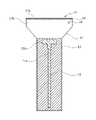
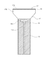
最初に、図1及び図2を参照して、本発明の一実施形態によるコンクリート止め用型枠部材11の構成を説明する。コンクリート止め用型枠部材11は、多孔質弾性体13と、多孔質弾性体13に埋設された芯材15と、これらを内部に収容する袋体17とを備える。
Hereinafter, several embodiments of a concrete fixing form member according to the present invention will be described with reference to the drawings.
First, with reference to FIG.1 and FIG.2, the structure of the
多孔質弾性体13は、外部から力を加えて押し潰すことにより容易に圧縮させることができ且つ復元性を有したスポンジ材質のものであり、例えば軟質発泡ポリウレタン、発泡ゴム、天然海綿などから作成することができる。また、多孔質弾性体13は、少なくとも一組の平行な側面を有した柱形状に形成されている。したがって、多孔質弾性体13の平行な側面に他の型枠部材11の多孔質弾性体13の平行な側面のうちの一つを隣接させるように複数の型枠部材11を配置することにより接触面積が広くなって、型枠部材として従来技術のような円筒状チューブを使用する場合よりも、安定した状態で隣接する型枠部材11同士を当接させることができ、型枠部材11の整列・設置が容易となる。多孔質弾性体13は、例えば、四角柱形状、六角柱形状、八角柱形状などの角柱形状や平行な側面の間を曲面で結合した形状とすることもできるが、図1及び図2に示されているように四角柱形状とすることが好ましい。これは、複数の型枠部材11を一列に整列させて設置したときに、これらの多孔質弾性体13の側面が共通する一つの面内に配置され、複数の型枠部材11によって構築される型枠の面が平坦となるので、コンクリートが硬化したときに平坦なコンクリート側面が得られるからである。
The porous
多孔質弾性体13の大きさは、底面の縦及び横寸法が50〜150mm程度、高さが300〜500mm程度とすることが好ましい。縦及び横寸法並びに高さが大きすぎるとコンクリートの圧力による多孔質弾性体13の変形が大きくなり、平坦なコンクリート側面が得られなくなるからである。
The size of the porous
芯材15は、多孔質弾性体13を補強するために用いられており、少なくともその一部が多孔質弾性体13内に埋設される。芯材15は、補強する機能を果たすことができれば、金属、プラスチック、木など任意の材料から作成することができる。しかしながら、鉄やアルミニウムなどの金属材料を用いた場合、型枠部材11が重くなる上に、錆びが発生する可能性があり、また、木を用いた場合、強度の問題や腐食の問題が発生し得る。したがって、軽量で錆びにくいプラスチック材料から作成することが好ましい。プラスチック材料としては、例えば、塩化ビニル、ポリプロピレン、ポリスチレン、ABS樹脂、ポリアミドなどを使用することができる。また、芯材15は、多孔質弾性体13を補強する機能を果たすことができれば、任意の形状とすることができる。
The
図1及び図2に示されている実施形態では、芯材15は、多孔質弾性体13の長手軸線方向(図1及び図2では上下方向)に延びる柱状部分15aと、柱状部分15の端部に接続されており且つ柱状部分15aと垂直(図1及び図2では水平方向)に延びる横棒部分15bとを含み、概略T字形状を有するようになっており、柱状部分15a及び横棒部分15bがともに多孔質弾性体13内に埋設されている。芯材15の柱状部分15aは、多孔質弾性体13を補強し、コンクリートからの圧力で型枠部材11が折れ曲がることを防止する機能を果たす部分であるので、多孔質弾性体13内に埋設されている必要がある。一方、芯材15の横棒部分15bは、型枠部材11の押し込みや引き抜きの際に持ち手として機能して型枠部材11の取り扱いを容易にするための部分であるので、型枠部材11の多孔質弾性体13内に埋設されている必要はない。したがって、横棒部分15bは、持ち手として利用しやすいように多孔質弾性体13の外部へ突出していてもよい。しかしながら、横棒部分15bは、図1及び図2に示されているように、多孔質弾性体13内に埋設されるように配置されることが好ましい。これは、芯材15を多孔質弾性体13内に完全に埋設させることにより、型枠部材11の取り扱いの際に芯材15が袋体17に直接的に接触して袋体17を損傷させることを防ぐためである。なお、図1及び図2に示されている実施形態のように横棒部分15bが多孔質弾性体13に埋設されている場合、多孔質弾性体13の端部を圧縮して多孔質弾性体13の上から横棒部分15bを把持することにより、横棒部分15bを持ち手として利用する。
In the embodiment shown in FIGS. 1 and 2, the
芯材15は、上述したように、任意の形状とすることができ、例えば、芯材15は単純な棒形状としてもよい。このような棒形状の芯材15は製造が容易であるという利点がある。また、芯材15の少なくとも一部を多孔質弾性体13の外部に突出させ、突出した部分の先端をリング形状又はU字形状にしてもよい。このように多孔質弾性体13の外部に突出した芯材15の先端をリング形状又はU字形状にすれば、この先端部分を把持することにより型枠部材11を隙間に挿入したり隙間から引き抜いたりしやすくなり、型枠部材11の取り扱い性を向上させることができる。
As described above, the
なお、芯材15を多孔質弾性体13に埋設する方法は、例えば、多孔質弾性体13を二分して、その間に芯材15を挟んだ状態で互いを接着してもよく、成形型の中に芯材15を配置した状態で多孔質弾性体13の材料を成形型内に注入して多孔質弾性体13を成形してもよい。
In addition, the method of embedding the
袋体17は、芯材15を埋設した多孔質弾性体13の全体を覆うために用いられており、芯材15を埋設した多孔質弾性体13の全体を収容できるものであれば、任意の形状及び厚さのものでよいが、芯材15を埋設した多孔質弾性体13を収容したときに袋体17が多孔質弾性体13とほぼ同じ輪郭となるように多孔質弾性体13周囲と袋体17との間にほとんど隙間が形成されないようになっていることが好ましい。これにより、袋体17にしわが発生することを防止する効果を奏する。また、袋体17は、ポリエチレン、ポリプロピレン、ポリエステル、ナイロン、TPU(熱可塑性ポリウレタン)などの軟質プラスチック樹脂、ポリ塩化ビニルなどのビニール樹脂などからなる樹脂製フィルムから作成される。ただし、袋体17が薄いと、しわになって、コンクリートの硬化の過程でコンクリートに噛まれ、コンクリートから袋体17を取り除くことが困難になる。また、袋体17の強度が弱いと、型枠部材11の取り扱いの過程で、袋体17が破けて穴があき、穴からコンクリートの水分や雨水が袋体17内へ浸入する恐れもある。したがって、強度やしわ形成防止の観点から、袋体17の厚さは0.1〜0.5mm程度とすることが好ましく、袋体17の材料として、TPUを用いることが好ましい。また、ビニール樹脂などを多層に重ねた多層フィルムを使用してもよく、袋体17を二重にしてもよい。
The
なお、図1及び図2に示されている実施形態では、芯材15によって補強された多孔質弾性体13は、芯材15の横棒部分15bが袋体17の口部17a側へ向くように袋体17に収容される。このように収容すれば、袋体17の口部17a側から多孔質弾性体13を介して芯材15の横棒部分15bを把持できるようになり、横棒部分15bを持ち手として多孔質弾性体13を袋体17から引き抜くことが容易になる。
In the embodiment shown in FIGS. 1 and 2, the porous
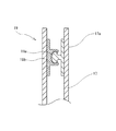
また、袋体17の口部17aには、袋体17の対向する側面同士を閉じ合わせて袋体17の口部17aを開閉自在に封止することができる封止部が設けられる。封止部は、袋体17の口部17aを開閉自在に封止し、封止したときに口部17aを密閉できるものであれば、任意のものでよい。例えば、封止部はジッパー19とすることができる。この場合、ジッパー19は、図3に示されるように、袋体17の口部17aの内側面の半分に設けられた雄型ジッパー部19aの先端の拡大部と袋体17の口部17aの内側面の残りの半分に設けられた雌型ジッパー部19bの凹部とを嵌合させることにより口部17aを封止する構成とすればよい。また、封止部は、雄型クリップの凸部と雌型クリップの凹部との間に袋体17の口部17aを挟んだ状態で雄型クリップと雌型クリップとを嵌合させることにより口部17aを封止するクリップによって構成してもよい。
In addition, the
さらに、袋体17は、封止部に隣接して、袋体17に多孔質弾性体13を収容した状態でも袋体17の側面同士を閉じ合わせることができる閉じ合わせ可能領域17bを有する。この閉じ合わせ可能領域17b(詳細には、閉じ合わせ可能領域17bのうち、封止部よりも多孔質弾性体13に近い側)には、空気抜き穴20が設けられている。空気抜き穴20は、直径3〜10mm程度とすることが好ましい。
Furthermore, the
空気抜き穴20は、型枠部材11を収縮させるときには、封止部を封止したまま袋体17の内部から空気を排出することを可能とさせる機能を果たし、多孔質弾性体13及び袋体17を容易に押し潰せるようにする。逆に、空気抜き穴20は、封止部を封止したまま型枠部材11を収縮させた状態から膨張させるときには、外部から袋体17の内部へ空気を吸い込むことを許容し得る。ところが、型枠部材11が膨張するときには、多孔質弾性体13が弾性力により元の形状に復帰しようとして袋体17を膨張させ、これに伴って空気が空気抜き穴20を通して急激に外部から袋体17内へ吸い込まれる。すると、封止部が封止された状態では封止部に隣接する閉じ合わせ可能領域17bにおいて対向する袋体17の側面の間が狭くなっているので、空気抜き穴20の周囲の袋体17内の圧力が急激に低下し、対向する袋体17の側面同士が吸い寄せられて閉じ合わさる。すなわち、空気抜き穴20は、実際には、型枠部材11を収縮させた状態から膨張させようとするときに、その周囲が密閉された状態に近くなり、外部から袋体17の内部へ空気を吸い込むことをほとんどできなくする。この結果、外部から型枠部材11に力を加えることを止めたときに、多孔質弾性体13が弾性力により元の形状に回復しようとして袋体17を膨張させようとしても、空気を袋体17の内部に吸い込むことができず、袋体17の膨張が妨げられる。したがって、外部から力を加えなくても、しばらくの間、型枠部材11は収縮した状態を維持する。また、空気抜き穴20の周囲の袋体17は単に閉じ合わされた状態であって完全に密閉されているわけではなく、閉じ合わされた袋体17の側面の間の隙間からわずかに空気が袋体17に吸い込まれていくので、しばらくすると、型枠部材11は多孔質弾性体13の弾性力で元の形状へ膨張していく。
The
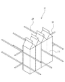
次に、図4を参照して、図1及び図2に示されている型枠部材11を用いてコンクリートの型枠を形成し、コンクリートの打ち継ぎを行う手順を説明する。
まず、コンクリートの型枠21を構築するために、図4に示されているように、予め組み立てられた支持鉄筋23に当接するように、所望する区分の境界に沿って四角柱形状の型枠部材11を互いに密着させて一列に並設する。このとき、全ての型枠部材11の向きを揃えて、隣接する型枠部材11の多孔質弾性体13の側面同士を当接させるように型枠部材11を整列させて配置する。これにより、隣接する型枠部材11の四角柱形状の多孔質弾性体13の側面が袋体17を介して面接触する形となるので、隣接する型枠部材11同士を安定した状態で密着させることができる。また、このように整列して配置された型枠部材11の多孔質弾性体13の側面は、結果として、一つの平坦な面を形成する。
Next, with reference to FIG. 4, a procedure for forming a concrete formwork using the
First, in order to construct a
型枠部材11を設置するときには、外部から型枠部材11に力を加えて袋体17内から空気を排出しつつ袋体17と共に多孔質弾性体13を押し潰して圧縮させることにより型枠部材11を収縮させた状態で配置して整列させ、その後、袋体17内に空気を吸い込ませつつ多孔質弾性体13を元の形状に戻すことにより型枠部材11を膨張させるとよい。このように収縮させた状態で型枠部材11を配置すれば、狭い隙間にでも型枠部材11を容易に押し込むことができる。また、型枠部材11を収縮させた状態で隣接する型枠部材に接触させて配置すれば、型枠部材11を元の形状に復帰させるときに、隣接する型枠部材11の多孔質弾性体13の間に挟まれた袋体17が多孔質弾性体13の弾性力によって互いに押し付けられ、隣接する型枠部材11同士を容易に密着させることができる。これにより、隣接する型枠部材11の間からコンクリートが漏出することを防止することができる。型枠部材11の他の設置方法として、膨張した状態の型枠部材11を隣接する型枠部材11に押し付けてやや圧縮させた状態で設置することにより、隣接する型枠部材11同士を密着させてもよい。
When the
図1及び図2に示されている型枠部材11では、袋体17において封止部(ジッパー19)に隣接する閉じ合わせ可能領域17bに空気抜き穴20が設けられており、封止部を封止した状態でも、空気抜き穴20を通じて袋体17内から空気を排出することができるので、外部から型枠部材11に力を加えれば、袋体17及び多孔質弾性体13を押し潰して圧縮でき、型枠部材11を収縮させることが容易である。また、型枠部材11を収縮させる際に、袋体17の封止部を開く必要がないので、封止部の開閉の手間を省くことができ、型枠21の構築作業の時間短縮に寄与すると共に、封止部の閉じ忘れにより袋体17の口部17aから水分が侵入することを防止することができる。
In the
また、型枠部材11を収縮させた状態で外部から型枠部材11に力を加えることを止めると、多孔質弾性体13が弾性力により元の形状に回復しようとして袋体17を膨張させようとする。しかしながら、上述したように、封止部が封止された状態で袋体17を膨張させようとすると、空気抜き穴20の周囲がほぼ密閉された状態となって、空気抜き穴20から袋体17内へ空気を吸い込めなくなり、袋体17の膨張が妨げられて、外部から力を加えなくても、しばらくの間、型枠部材11は収縮させられた状態を維持する。このように型枠部材11が収縮させられた状態を維持している間に型枠部材11の設置を行えば、狭い隙間などにも型枠部材11を押しこみやすくなり、型枠部材11の設置が容易になる。
Further, when the application of force to the
さらに、空気抜き穴20の周囲の袋体17は単に閉じ合わされた状態であって完全に密閉されているわけではなく、閉じ合わされた袋体17の側面の間の隙間からわずかに空気が袋体17に吸い込まれていくので、しばらくすると、型枠部材11は多孔質弾性体13の弾性力で元の形状に戻っていく。したがって、収縮した状態で型枠部材11を設置した後、封止部をわざわざ開かなくても、しばらくすれば、型枠部材11が再び膨張して、隣接する型枠部材11が多孔質弾性体13の弾性力で互いに密着し、その間からコンクリートが漏出することを防止できるようになる。
Further, the
このように、封止部を封止したままで型枠部材11の収縮及び膨張をさせることができるので、通常の設置作業では、袋体17の口部17aを封止部によって封止したまま設置作業を行うことができる。よって、封止部の閉め忘れが発生せず、袋体の口部17aから雨水などの水分が袋体17内に侵入することが防止される。また、空気抜き穴20は小さく、袋体17の側面(閉じ合わせ可能領域17b)に設けられているので、空気抜き穴20から水分が袋体17に侵入することもほとんどない。したがって、金属材料から芯材15を形成した場合でも、芯材15の錆びの発生が抑制される。また、雨水のような水分によって袋体17内の多孔質弾性体13が劣化することを防ぐので、繰り返しの使用が可能になる。
Thus, since the
次に、複数の型枠部材11によって構築された型枠21によって又は型枠21とすでに硬化したコンクリートとによって囲まれた領域の内側にコンクリートを打設する。型枠部材11は支持鉄筋23に沿って配置され支持鉄筋23によって支持されているので、打設されたコンクリートから圧力が作用しても型枠部材11を設置位置に保持することができる。また、型枠部材11の多孔質弾性体13は芯材15によって補強されているので、コンクリートから圧力が作用しても簡単には折れ曲がらない。したがって、所望される位置にコンクリート側面を得ることができる。
Next, concrete is placed inside a region surrounded by the
コンクリートが硬化すると、型枠部材11は除去される。型枠部材11を除去するときには、まず、封止部(例えばジッパー19)を開き、多孔質弾性体13内に埋設される又は多孔質弾性体13から突出する芯材15の横棒部分15bを把持して袋体17から多孔質弾性体13を引き抜く。多孔質弾性体13は、容易に圧縮変形し、また、硬化したコンクリートの粗い面ではなく、接触抵抗が小さい袋体17の滑らかな表面に接しているので、容易に引き抜くことができる。次に、硬化したコンクリートの側面から袋体17を除去する。多孔質弾性体13がすでに袋体17から引き抜かれているので、コンクリートの側面からの袋体17の除去は容易となる。なお、袋体と硬化したコンクリートとの間の摩擦抵抗は小さいので、多孔質弾性体13を袋体17に収容したまま型枠部材11をコンクリートから除去することも可能である。
When the concrete is hardened, the
従来技術の円筒状チューブは軽量で扱やすがこれを並べて型枠を形成する場合には、隣接する円筒状チューブの間に形成される谷間にコンクリートが入り込む形になってコンクリートの側面に尾根のように突出した部分が形成され、平坦なコンクリート側面が得られず、これを打継面として利用する場合、コンクリートの側面の整形が必要になっていた。これに対して、本実施形態では、複数の型枠部材11によって構築された型枠21は平坦な面を形成するので、型枠部材11が除去されると、型枠部材11に接していたコンクリートの部分に平坦なコンクリート側面が得られる。したがって、硬化後のコンクリートの打継面を整形する作業が軽減される。
Prior art cylindrical tubes are lightweight and easy to handle, but when they are lined up to form a formwork, the concrete enters the valleys formed between adjacent cylindrical tubes, and the side of the concrete has a ridge. Thus, the projecting portion is formed, and a flat concrete side surface cannot be obtained. When this is used as a joining surface, it is necessary to shape the concrete side surface. On the other hand, in this embodiment, since the
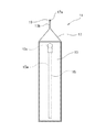
以上、図1及び図2に示されている一つの実施形態を参照して、本発明の型枠部材11を説明したが、本発明はこの実施形態に限定されるものではない。例えば、図示される実施形態では、袋体17の封止部がジッパー19によって構成されているが、クリップなど他の機構によって封止部を構成してもよい。また、図1及び図2に示されている実施形態では、封止部に隣接する袋体17の閉じ合わせ可能領域17bに空気抜き穴20が設けられているが、空気抜き穴20は必須の構成ではなく、図5に示されているように、袋体17に空気抜き穴20を設けなくてもよい。図5に示されている型枠部材11’のその他の構成は、図1及び図2に示されている型枠部材11と同じであるので、ここでは詳しく説明しない。
As mentioned above, although the
なお、図5に示されている型枠部材11’には空気抜き穴20が設けられていないので、コンクリートの型枠を形成するために型枠部材11’を設置するときには、封止部(例えばジッパー19)を開いた状態で、袋体17内から空気を排出しつつ袋体17と共に多孔質弾性体13を押し潰して圧縮させて、圧縮させた状態で封止部を閉じることにより収縮させたまま型枠部材11’を整列させ、その後、封止部を開いて袋体17内に空気を吸い込ませつつ多孔質弾性体13を元の形状に戻すことにより型枠部材11を膨張させる。また、封止部を開いたまま、型枠部材11’を隣接する型枠部材11’に押し付けてやや圧縮させた状態で設置するようにしてもよい。さらに、型枠部材11’を整列させて並設した後は、袋体17の口部17aから袋体17内への雨水などの水分の侵入を防止するために、封止部(例えばジッパー19)を閉じて、袋体17を密封する。
Since the
図5に示されている実施形態では、型枠部材11’の設置時に封止部の開閉が必要になり、図1及び図2に示されている実施例の型枠部材11と比較して、設置作業に必要な時間が長くなる。一方で、空気抜き穴20がなく、封止部を閉じれば、袋体17を完全に密封することができるので、型枠部材11’の設置後に封止部を閉じて袋体17の口部17aを封止すれば、雨水などの水分が袋体17内に侵入することを完全に防止することができ、金属材料から芯材15を形成した場合でも、芯材15に錆びが発生することを防止することができる利点がある。さらに、袋体17内から空気を排出することにより袋体17と共に多孔質弾性体13を圧縮し、この状態で封止部を閉じて袋体17の口部17aを封止すれば、型枠部材11’を収縮させた状態に保つことができる。したがって、保管時や搬送時の型枠部材11’の占有体積を小さくできる利点も得られる。
In the embodiment shown in FIG. 5, it is necessary to open and close the sealing portion when installing the
11 型枠部材
11’ 型枠部材
13 多孔質弾性体
15 芯材
15a 柱状部分
15b 横棒部分
17 袋体
17a 口部
17b 閉じ合わせ可能領域
19 ジッパー
DESCRIPTION OF
Claims (6)
樹脂製の袋体と、少なくとも一組の平行な側面を有し該袋体の内部に収容された柱状の多孔質弾性体と、少なくとも一部が前記多孔質弾性体に埋設された芯材とを備え、前記袋体の口部に該口部を開閉自在に封止する封止部が設けられていることを特徴とするコンクリート止め用型枠部材。 In concrete jointing, it is a formwork member for concrete that is installed side by side to form a formwork for concrete,
A resin-made bag, a columnar porous elastic body having at least one pair of parallel side surfaces and housed in the bag, and a core material at least partially embedded in the porous elastic body; And a sealing part for sealing the mouth part so that the mouth part can be freely opened and closed is provided at the mouth part of the bag body.
Priority Applications (1)
| Application Number | Priority Date | Filing Date | Title |
|---|---|---|---|
| JP2010152682A JP5073789B2 (en) | 2010-07-05 | 2010-07-05 | Concrete formwork member |
Applications Claiming Priority (1)
| Application Number | Priority Date | Filing Date | Title |
|---|---|---|---|
| JP2010152682A JP5073789B2 (en) | 2010-07-05 | 2010-07-05 | Concrete formwork member |
Publications (2)
| Publication Number | Publication Date |
|---|---|
| JP2012012896A JP2012012896A (en) | 2012-01-19 |
| JP5073789B2 true JP5073789B2 (en) | 2012-11-14 |
Family
ID=45599642
Family Applications (1)
| Application Number | Title | Priority Date | Filing Date |
|---|---|---|---|
| JP2010152682A Active JP5073789B2 (en) | 2010-07-05 | 2010-07-05 | Concrete formwork member |
Country Status (1)
| Country | Link |
|---|---|
| JP (1) | JP5073789B2 (en) |
Cited By (1)
| Publication number | Priority date | Publication date | Assignee | Title |
|---|---|---|---|---|
| JP6159899B1 (en) * | 2017-02-22 | 2017-07-05 | 東邦アストリー株式会社 | Concrete joint spacer |
Families Citing this family (2)
| Publication number | Priority date | Publication date | Assignee | Title |
|---|---|---|---|---|
| JP6017718B1 (en) * | 2016-02-19 | 2016-11-02 | 武士 廣瀬 | Concrete joint frame material |
| JP7561332B2 (en) * | 2019-11-11 | 2024-10-04 | 龍治 植村 | Air Wall XZ |
Family Cites Families (5)
| Publication number | Priority date | Publication date | Assignee | Title |
|---|---|---|---|---|
| JPS5929070Y2 (en) * | 1978-10-06 | 1984-08-21 | 清水建設株式会社 | concrete stopper |
| JPH0385375U (en) * | 1989-12-21 | 1991-08-29 | ||
| JP2826702B2 (en) * | 1994-08-09 | 1998-11-18 | トーヨー産業株式会社 | Formwork |
| JP2000027438A (en) * | 1998-07-13 | 2000-01-25 | Taisei Corp | Vertical joining method of concrete horizontal member |
| JP4958081B2 (en) * | 2005-09-22 | 2012-06-20 | 株式会社京都スペーサー | Con stop sponge |
-
2010
- 2010-07-05 JP JP2010152682A patent/JP5073789B2/en active Active
Cited By (1)
| Publication number | Priority date | Publication date | Assignee | Title |
|---|---|---|---|---|
| JP6159899B1 (en) * | 2017-02-22 | 2017-07-05 | 東邦アストリー株式会社 | Concrete joint spacer |
Also Published As
| Publication number | Publication date |
|---|---|
| JP2012012896A (en) | 2012-01-19 |
Similar Documents
| Publication | Publication Date | Title |
|---|---|---|
| JP5073789B2 (en) | Concrete formwork member | |
| WO1997045601A1 (en) | Method of joining concrete members, joined construction and molding die | |
| KR101456055B1 (en) | Rebar coupler and method for coupling rebar | |
| JP3968303B2 (en) | Reinforcing bar connection method using expansion joint and expansion joint | |
| WO2017073546A1 (en) | Storage tank and method for constructing same | |
| JPH08333891A (en) | Hollow panel for formwork and formwork system using the same | |
| JP2010265662A (en) | Buckling restraining brace | |
| CN105492708A (en) | Floor deck and manufacturing method thereof | |
| JP6525765B2 (en) | Buckling-restrained brace and method of making the same | |
| KR101851536B1 (en) | Wave type tank and constructing method thereof | |
| KR101978748B1 (en) | Deck Plate With Compression Parts Reinforcement Structure | |
| KR200461421Y1 (en) | Panel with cleaning hole | |
| JP2002206338A (en) | Plastic panel | |
| KR102041401B1 (en) | Method for changing width of aluminum panel used in construction of building | |
| JP6017718B1 (en) | Concrete joint frame material | |
| JP5314334B2 (en) | Joint frame material | |
| JP4598028B2 (en) | Residual form for rubber impact resistance | |
| JP3212109U (en) | Concrete joint spacer | |
| JP3151521U (en) | Covering concrete adhesion prevention cover for rebar | |
| JP6491306B1 (en) | Water blocking plate, water blocking structure using water blocking plate, and water blocking method using water blocking plate | |
| JP2829564B2 (en) | Plastic panel for concrete formwork | |
| JPH047783B2 (en) | ||
| JP4271170B2 (en) | Seal joint for precast floor slab connection | |
| JP2008038453A (en) | Box culvert and method for producing the same | |
| JP2002201637A (en) | Head end isolation member for cast-in-place pile |
Legal Events
| Date | Code | Title | Description |
|---|---|---|---|
| TRDD | Decision of grant or rejection written | ||
| A01 | Written decision to grant a patent or to grant a registration (utility model) |
Free format text: JAPANESE INTERMEDIATE CODE: A01 Effective date: 20120724 |
|
| A01 | Written decision to grant a patent or to grant a registration (utility model) |
Free format text: JAPANESE INTERMEDIATE CODE: A01 |
|
| A61 | First payment of annual fees (during grant procedure) |
Free format text: JAPANESE INTERMEDIATE CODE: A61 Effective date: 20120822 |
|
| R150 | Certificate of patent or registration of utility model |
Ref document number: 5073789 Country of ref document: JP Free format text: JAPANESE INTERMEDIATE CODE: R150 Free format text: JAPANESE INTERMEDIATE CODE: R150 |
|
| FPAY | Renewal fee payment (event date is renewal date of database) |
Free format text: PAYMENT UNTIL: 20150831 Year of fee payment: 3 |
|
| R250 | Receipt of annual fees |
Free format text: JAPANESE INTERMEDIATE CODE: R250 |
|
| R250 | Receipt of annual fees |
Free format text: JAPANESE INTERMEDIATE CODE: R250 |
|
| R250 | Receipt of annual fees |
Free format text: JAPANESE INTERMEDIATE CODE: R250 |
|
| R250 | Receipt of annual fees |
Free format text: JAPANESE INTERMEDIATE CODE: R250 |
|
| R250 | Receipt of annual fees |
Free format text: JAPANESE INTERMEDIATE CODE: R250 |
|
| R250 | Receipt of annual fees |
Free format text: JAPANESE INTERMEDIATE CODE: R250 |
|
| R250 | Receipt of annual fees |
Free format text: JAPANESE INTERMEDIATE CODE: R250 |