JP5073774B2 - Dissimilar liquid mixture detection device and method - Google Patents
Dissimilar liquid mixture detection device and method Download PDFInfo
- Publication number
- JP5073774B2 JP5073774B2 JP2010091200A JP2010091200A JP5073774B2 JP 5073774 B2 JP5073774 B2 JP 5073774B2 JP 2010091200 A JP2010091200 A JP 2010091200A JP 2010091200 A JP2010091200 A JP 2010091200A JP 5073774 B2 JP5073774 B2 JP 5073774B2
- Authority
- JP
- Japan
- Prior art keywords
- liquid
- belt
- endless track
- detection
- detection plate
- Prior art date
- Legal status (The legal status is an assumption and is not a legal conclusion. Google has not performed a legal analysis and makes no representation as to the accuracy of the status listed.)
- Expired - Fee Related
Links
- 239000007788 liquid Substances 0.000 title claims description 237
- 238000001514 detection method Methods 0.000 title claims description 135
- 238000000034 method Methods 0.000 title description 13
- 239000000203 mixture Substances 0.000 title description 5
- XLYOFNOQVPJJNP-UHFFFAOYSA-N water Substances O XLYOFNOQVPJJNP-UHFFFAOYSA-N 0.000 claims description 52
- 230000008859 change Effects 0.000 claims description 28
- 238000009434 installation Methods 0.000 claims description 9
- 239000000498 cooling water Substances 0.000 description 9
- 230000033001 locomotion Effects 0.000 description 9
- 238000010586 diagram Methods 0.000 description 8
- 239000000463 material Substances 0.000 description 8
- 238000002485 combustion reaction Methods 0.000 description 7
- 230000005540 biological transmission Effects 0.000 description 5
- 239000013505 freshwater Substances 0.000 description 5
- 239000011521 glass Substances 0.000 description 5
- 229920003023 plastic Polymers 0.000 description 3
- 238000010248 power generation Methods 0.000 description 3
- 238000011109 contamination Methods 0.000 description 2
- 230000007613 environmental effect Effects 0.000 description 2
- 230000005484 gravity Effects 0.000 description 2
- 230000007257 malfunction Effects 0.000 description 2
- 238000005259 measurement Methods 0.000 description 2
- 230000007246 mechanism Effects 0.000 description 2
- 238000012544 monitoring process Methods 0.000 description 2
- 238000007790 scraping Methods 0.000 description 2
- 239000000126 substance Substances 0.000 description 2
- 239000012615 aggregate Substances 0.000 description 1
- 230000008901 benefit Effects 0.000 description 1
- 230000003139 buffering effect Effects 0.000 description 1
- 239000003795 chemical substances by application Substances 0.000 description 1
- 230000003749 cleanliness Effects 0.000 description 1
- 238000001816 cooling Methods 0.000 description 1
- 239000012535 impurity Substances 0.000 description 1
- 230000006698 induction Effects 0.000 description 1
- JEIPFZHSYJVQDO-UHFFFAOYSA-N iron(III) oxide Inorganic materials O=[Fe]O[Fe]=O JEIPFZHSYJVQDO-UHFFFAOYSA-N 0.000 description 1
- 230000001678 irradiating effect Effects 0.000 description 1
- 239000002184 metal Substances 0.000 description 1
- 238000012986 modification Methods 0.000 description 1
- 230000004048 modification Effects 0.000 description 1
- 230000035699 permeability Effects 0.000 description 1
- 239000000843 powder Substances 0.000 description 1
- 230000003449 preventive effect Effects 0.000 description 1
- 239000005871 repellent Substances 0.000 description 1
- 238000004381 surface treatment Methods 0.000 description 1
- 239000002352 surface water Substances 0.000 description 1
- 238000002834 transmittance Methods 0.000 description 1
- 239000002351 wastewater Substances 0.000 description 1
Images

Landscapes
- Investigating Or Analysing Materials By Optical Means (AREA)
Description
本発明は、貯蔵目的である液体に対して、異種の液体が混入しているか否かを検知するための異種液体混入検知装置および方法に関する。特に人の目視による常時監視が困難な設備での異種液体の混入検知、例えば、船舶における船舶内燃機の冷却水清水タンクなどへの油等の異種液体の混入検知、工場設備・発電設備等の蒸気を用いた熱交換器の冷却水への油等の異種液体の混入検知、プール・浴場等での水・お湯への異種液体の混入検知、工場排水の清浄度監視などに適用される。 The present invention relates to a heterogeneous liquid mixture detection apparatus and method for detecting whether or not a heterogeneous liquid is mixed in a liquid for storage purposes. In particular, detection of mixing of different liquids in equipment that is difficult to monitor by human eyes at all times, for example, detection of mixing of different liquids such as oil in a cooling water fresh water tank of a ship internal combustion engine in a ship, steam from factory facilities, power generation facilities, etc. It is applied to detection of mixing of different liquids such as oil in the cooling water of heat exchangers using water, detection of mixing of different liquids into water and hot water in pools and bathhouses, etc., and monitoring of cleanliness of factory waste water.
従来、異種液体の混入を検知する異種液体検知システムとして、油膜・漏油検知器が知られている。筐体の構造として、検知液面に対して浮子を浮かべて浮子内にセンサを組み込んで液面を監視するフロート式と、貯蔵タンク等の喫水面近くの壁面に固定子を取り付け、固定子内にセンサを組み込んで液面を監視する固定式とがある。また、異種液体の検知方式として透過式と静電容量式がある。 Conventionally, an oil film / leakage detector is known as a different liquid detection system for detecting mixing of different liquids. As a housing structure, a float type that floats on the detection liquid level and incorporates a sensor in the float to monitor the liquid level, and a stator is attached to the wall near the draft surface such as a storage tank. There is a fixed type that incorporates a sensor and monitors the liquid level. Further, there are a transmission type and a capacitance type as a detection method of the different liquid.
透過式は、水が循環する配管の一側面の対向する位置(上下、左右等)にガラス部を設け、ガラス部を挟んで投光部と受光部を設け、投光部からガラス部を介して光を照射し、液面を通過した透過光を受光部で受け、当該透過光の光度を計測して油分を検知する方法である。
なお、透過式は光を透過させる必要があるため、透過度の低い液体に対する異種液体検知システムには不向きである。例えば、内燃機関等の冷却油等と熱交換する循環水の場合は循環水中に防錆剤が入っているためにもともと透過度が低く、透過式での油分の検知は不向きであると言われている。そこで、船舶における船舶内燃機の冷却水清水タンクなどへの異種液体検知システムなどに用いられることが多い。
In the transmission type, a glass part is provided on the opposite side (top and bottom, left and right, etc.) of one side of the pipe through which water circulates, and a light projecting part and a light receiving part are provided across the glass part. This is a method of detecting oil content by irradiating light and receiving transmitted light that has passed through the liquid level at a light receiving unit, measuring the luminous intensity of the transmitted light.
In addition, since the transmission type needs to transmit light, it is not suitable for a heterogeneous liquid detection system for a liquid with low transmittance. For example, in the case of circulating water that exchanges heat with cooling oil or the like of an internal combustion engine or the like, it is said that the permeability is low due to the presence of a rust preventive agent in the circulating water, and it is said that the permeation type oil content detection is not suitable. ing. Therefore, it is often used in a different liquid detection system for a cooling water fresh water tank or the like of a ship internal combustion engine in a ship.
静電容量式は、液体、粉体、塊体などのあらゆる物質がもっている固有の誘導率を利用した検知方法である。検知液面の表面に漂う物質の静電容量を検出し、その変化を捉える方法である。
なお、静電容量式は、静電容量の変化を捉えるために異種液体の量・厚みがある程度必要となるという問題がある。例えば、異種液体が油の場合では油膜の厚みが1cm以上ないと静電容量の変化を検知できない。つまり、少量の異種液体の検知には不向きな方式であると言える。
The electrostatic capacitance type is a detection method that uses the inherent induction rate possessed by all substances such as liquids, powders, and aggregates. This is a method of detecting the capacitance of substances floating on the surface of the detection liquid and capturing the change.
In addition, the capacitance type has a problem that a certain amount and thickness of different kinds of liquids are required in order to capture a change in capacitance. For example, when the dissimilar liquid is oil, a change in capacitance cannot be detected unless the thickness of the oil film is 1 cm or more. That is, it can be said that this method is not suitable for detecting a small amount of different liquids.
また、静電容量は、温度、湿度などの影響を受けやすいため、検知方式として静電容量式を用いる場合には温度、湿度等の計測条件を一定にする必要がある。 In addition, since the capacitance is easily affected by temperature, humidity, and the like, it is necessary to make measurement conditions such as temperature and humidity constant when using the capacitance method as a detection method.
上記従来の異種液体検知システムでは、筐体の構成がフロート式、固定式のいずれであっても、また、異種液体の検知方式が透過式、静電容量式のいずれであっても、検知液面が静止していることが条件となる。もし、検知液面に波紋や流れが存在すると、浮子式の場合は浮子自体が揺れ動いてしまい、固定式の場合も固定子に対する検知液面の水位や状態が安定しないため、検知結果にノイズが混入することとなり、信頼性の高い異種液体の検知ができない。 In the above-described conventional different liquid detection system, the detection liquid can be used regardless of whether the casing configuration is a float type or a fixed type, and whether the different liquid detection method is a transmission type or a capacitance type. The condition is that the surface is stationary. If ripples or flows are present on the detection liquid level, the float itself swings in the case of the float type, and the water level and state of the detection liquid level with respect to the stator are not stable even in the case of the fixed type. Therefore, it is impossible to detect a different kind of liquid with high reliability.
また、上記従来の異種液体検知システムでは、筐体の構成がフロート式、固定式のいずれであっても、また、異種液体の検知方式が透過式、静電容量式のいずれであっても、装置が液面上に設置されなければならないが、検知液面に波紋や流れが存在すると、装置内に液体が浸水してしまい、不具合が生じるおそれがある。 Further, in the above-mentioned conventional different liquid detection system, the configuration of the housing is either a float type or a fixed type, and the different type liquid detection method is either a transmission type or a capacitance type. Although the apparatus must be installed on the liquid surface, if ripples or flows exist on the detection liquid surface, the liquid may be submerged in the apparatus, which may cause a problem.
また、異種液体の検知方式が静電容量式である場合は、温度、湿度などの影響を受けないように配慮する必要があるが、異種液体を検知する液面の温度や湿度等の計測条件を一定に保つことは容易ではない。 In addition, when the detection method for different types of liquids is a capacitance type, it is necessary to take care not to be affected by temperature, humidity, etc., but the measurement conditions such as the temperature and humidity of the liquid level for detecting different types of liquids are necessary. It is not easy to keep constant.
このように、上記従来の異種液体検知システムでは、検知液面の静止状態、検知液面の温度、湿度環境などの影響を受けると、検知の信頼性の低下を招くという問題があった。 As described above, in the above-described conventional different liquid detection system, there is a problem in that the detection reliability is lowered when the detection liquid level is influenced by the stationary state of the detection liquid level, the temperature of the detection liquid level, the humidity environment, and the like.
上記問題点に鑑み、本発明は、装置の設置場所、環境温度、異種液体の混入を検知する液面の状態などの影響を受けにくく、検知信頼性が高い異種液体検知システムおよび検知方法を提供することを目的とする。また、本発明は、装置の故障が少なく、高い耐久性を備えた異種液体検知システムおよび検知方法を提供することを目的とする。 In view of the above problems, the present invention provides a different liquid detection system and a detection method that are less affected by the installation location of the apparatus, the environmental temperature, the state of the liquid level for detecting the mixing of different liquids, and the like, and have high detection reliability. The purpose is to do. Another object of the present invention is to provide a heterogeneous liquid detection system and a detection method that have few device failures and high durability.
上記目的を達成するため、本発明の異種液体検知システムは、正常液体に対して異種液体の混入を検知する異種液体検知システムであって、タンク内の検査対象液体の喫水線の下方と上方を結ぶ無限軌道で回転する無限軌道式ベルト装置と、前記無限軌道に沿って移動する前記無限軌道式ベルト装置のベルト面に対して歯が当たるように配置されたスクレーパーと、前記スクレーパーの歯により前記無限軌道式ベルト装置のベルト面から掻き落とされた液体を受け取って透光性を有する検知プレートを通過させてから前記タンク中に戻す液体流路と、前記検知プレートを挟んで対向する発光部および受光部とを備え、前記受光部で受光される信号変化を検出して前記正常液体とは異なる前記異種液体の混入を検知するセンサとを備えた異種液体検知システムである。 In order to achieve the above object, a different liquid detection system according to the present invention is a different liquid detection system that detects the mixing of a different liquid with respect to a normal liquid, and connects the lower and upper sides of the water line of the liquid to be inspected in the tank. An endless track belt device that rotates on an endless track, a scraper that is disposed so that teeth contact the belt surface of the endless track belt device that moves along the endless track, and the endlessness of the scraper teeth. The liquid flow path that receives the liquid scraped off from the belt surface of the orbital belt device, passes the translucent detection plate and returns it to the tank, and the light emitting portion and the light receiving member that are opposed to each other with the detection plate interposed therebetween. And a sensor for detecting a change in the signal received by the light receiving unit and detecting the mixing of the different liquid different from the normal liquid. A detection system.
なお、前記スクレーパーの配置位置は、前記無限軌道式ベルト装置の前記無限軌道のうち前記ベルトの移動方向が上方から下方へ移動する経路中で前記液面の喫水線より上の位置であることが好ましく、さらに言えば、前記液面の喫水線より上の位置とは、前記液面に生じ得る波の影響を受けない高さの位置であることが好ましい。 It is preferable that the scraper is disposed at a position above the draft line of the liquid level in a path in which the moving direction of the belt moves from the upper side to the lower side in the endless track of the endless track type belt device. Furthermore, it is preferable that the position above the waterline of the liquid level is a position at a height that is not affected by waves that may occur on the liquid level.
上記構成により、無限軌道式ベルト装置が液面の喫水線の下方と上方と間を結ぶ無限軌道で回転するため、液体を貯蔵するタンク等が多少揺れ動いても無限軌道式ベルト装置により確実に、液面付近の液体を表面張力や表面摩擦などで上方に掬い上げることができ、また、スクレーパーにより確実にセンサ内に掻き取ることができ、センサにて高い信頼性の異種液体検知が可能となる。従来の浮子式のセンサや固定式のセンサではタンク等の揺れ動きにより生じてしまう不具合が本発明の異種液体検知システムでは発生しない。 With the above configuration, the endless track belt device rotates on the endless track connecting the lower and upper sides of the liquid level water line, so even if the liquid storage tank or the like is slightly swung, the endless track belt device reliably The liquid in the vicinity of the surface can be scooped upward by surface tension, surface friction, etc., and can be reliably scraped into the sensor by the scraper, so that the sensor can detect a highly reliable different liquid. The conventional floating type sensor or the fixed type sensor does not cause a problem that occurs due to the shaking motion of the tank or the like in the heterogeneous liquid detection system of the present invention.
次に、無限軌道式ベルト装置のベルトの取り付けに関して、前記無限軌道式ベルト装置のベルトの上方のプーリーは設置箇所の壁面に対して固定され、前記無限軌道式ベルト装置のベルトの下方のプーリーは設置箇所の壁面に対して固定せずに遊離状態として前記ベルトを介して吊り下がった状態とし、前記ベルトに対して前記下方のプーリーの重量のテンションがかかり、前記ベルトが鉛直下方に垂れ下がった状態となるものであることが好ましい。
上記構成により、下方のプーリーを設置箇所の壁面に固定する必要はないために設置が容易であるとともに、ベルトが常に鉛直下方に保たれ、また、ベルトにかかるテンションも略一定となる。
Next, regarding the installation of the belt of the endless track belt device, the pulley above the belt of the endless track belt device is fixed to the wall surface of the installation location, and the pulley below the belt of the endless track belt device is A state in which the belt is suspended through the belt without being fixed to the wall surface of the installation location, the weight of the lower pulley is applied to the belt, and the belt hangs vertically downward It is preferable that
According to the above configuration, since it is not necessary to fix the lower pulley to the wall surface of the installation location, the installation is easy, the belt is always kept vertically downward, and the tension applied to the belt is substantially constant.
センサについては多様なタイプを適用することができる。
例えば、検知プレート上の液体の色比率の変化を検出するタイプのセンサがある。このタイプのセンサは、前記発光部と前記受光部を結ぶ線が前記検知プレートに対して直角に取り付けられる。
このタイプのセンサであれば、船体の揺れや光源のゆらぎなどで受光量の強度変化が起こったとしても光の色比率は変化しないため誤動作が起こる可能性が低い。つまり、ノイズの影響を受けにくい方式であると言える。もし、センサが受光量の強度変化を判定するものであれば、船体の揺れによる光の反射や光源のゆらぎやなどで生じる光の受光量の強度変化を捉えて誤動作が起こる可能性がある。
次に、検知プレート上の前記液体による屈折率の変化を検出するタイプのセンサがある。このタイプのセンサは、前記発光部と前記受光部を結ぶ線が前記検知プレートに対して斜めに取り付けられる。つまり、液体が介在する検知プレートに対して屈折率の変化を捉えやすい角度となるように取り付けておく。
Various types of sensors can be applied.
For example, there is a type of sensor that detects a change in the color ratio of the liquid on the detection plate. In this type of sensor, a line connecting the light emitting unit and the light receiving unit is attached at a right angle to the detection plate.
With this type of sensor, even if the intensity of light received changes due to fluctuations in the hull or fluctuations in the light source, the color ratio of light does not change, so there is little possibility of malfunction. In other words, it can be said that the system is not easily affected by noise. If the sensor determines a change in the intensity of the received light amount, a malfunction may occur due to a change in the intensity of the received light amount caused by light reflection or light source fluctuation caused by the hull shaking.
Next, there is a type of sensor that detects a change in refractive index due to the liquid on the detection plate. In this type of sensor, a line connecting the light emitting part and the light receiving part is attached obliquely to the detection plate. That is, it is attached at an angle that makes it easy to detect the change in the refractive index with respect to the detection plate in which the liquid is interposed.
次に、本発明の異種液体検知方法は、正常液体に対して異種液体の混入を検知する異種液体検知方法であって、検査対象液体の喫水線の下方と上方を結ぶ無限軌道で回転する無限軌道式ベルト装置により前記液面から液体を引き揚げ、前記無限軌道に沿って移動する前記無限軌道式ベルト装置のベルト面に対して歯が当たるように配置されたスクレーパーにより前記液体を掻き落とし、前記スクレーパーの歯により前記無限軌道式ベルト装置のベルト面から掻き落とされた液体を受け取って透光性を有する検知プレートを通過させ、前記検知プレートを挟んで対向する発光部から発射され受光部で受光される信号変化をセンサにより検出し、前記正常液体とは異なる前記異種液体の混入を検知する異種液体検知方法である。 Next, the heterogeneous liquid detection method of the present invention is a heterogeneous liquid detection method for detecting the mixing of a heterogeneous liquid with respect to a normal liquid, and is an infinite orbit that rotates in an infinite orbit connecting the lower and upper draft lines of the liquid to be inspected. The scraper is arranged to lift the liquid from the liquid surface by a belt-type belt device, scrape the liquid by a scraper arranged so that teeth contact the belt surface of the endless track-type belt device that moves along the endless track, and the scraper The liquid scraped off from the belt surface of the endless track belt device by the teeth is passed through the translucent detection plate, emitted from the light emitting portion opposed to the detection plate, and received by the light receiving portion. This is a different liquid detection method in which a change in signal is detected by a sensor to detect mixing of the different liquid different from the normal liquid.
上記方法によれば、無限軌道式ベルト装置が液面の喫水線の下方と上方と間を結ぶ無限軌道で回転するため、液体を貯蔵するタンク等が多少揺れ動いても無限軌道式ベルト装置により確実に、液面付近の液体を表面張力や表面摩擦などで上方に掬い上げることができ、また、スクレーパーにより確実にセンサ内に掻き取ることができ、センサにて高い信頼性の異種液体検知が可能となる。従来の浮子式のセンサや固定式のセンサではタンク等の揺れ動きにより生じてしまう不具合が本発明の異種液体検知方法では発生しない。 According to the above method, the endless track type belt device rotates on the endless track connecting the lower and upper sides of the liquid level water line, so that the endless track type belt device reliably ensures even if the tank for storing the liquid is slightly swung. , Liquid near the liquid level can be lifted up by surface tension, surface friction, etc., and scraper can be surely scraped into the sensor, making it possible to detect highly reliable different liquids with the sensor Become. In the conventional floating type sensor and the fixed type sensor, the problem that occurs due to the shaking movement of the tank or the like does not occur in the different liquid detection method of the present invention.
本発明の異種液体検知システムによれば、無限軌道式ベルト装置が液面の喫水線の下方と上方と間を結ぶ無限軌道で回転するため、液体を貯蔵するタンク等が多少揺れ動いても無限軌道式ベルト装置により確実に、液面付近の液体を表面張力や表面摩擦などで上方に掬い上げることができ、また、スクレーパーにより確実にセンサ内に掻き取ることができ、センサにて高い信頼性の異種液体検知が可能となる。従来の浮子式のセンサや固定式のセンサではタンク等の揺れ動きにより生じてしまう不具合が本発明の異種液体検知システムでは発生しない。 According to the heterogeneous liquid detection system of the present invention, the endless track type belt device rotates on an endless track connecting the lower and upper sides of the liquid surface water line, so that the endless track type even if the tank for storing the liquid is slightly swung. The belt device can reliably lift up the liquid near the liquid surface by surface tension, surface friction, etc., and can be scraped into the sensor reliably by the scraper. Liquid detection is possible. The conventional floating type sensor or the fixed type sensor does not cause a problem that occurs due to the shaking motion of the tank or the like in the heterogeneous liquid detection system of the present invention.
以下、本発明の異種液体検知システムの実施例を説明する。
本発明の異種液体検知システムは、例えば、船舶における船舶内燃機の冷却水清水タンク等への油等の異種液体の混入検知、工場設備・発電設備等の蒸気を用いた熱交換器の冷却水への油等の異種液体の混入検知、プール・浴場等での水・お湯への異種液体の混入検知、工場排水の清浄度監視などに適用されるが、ここでは、正常状態で存在する正常液体を水とし、当該水に対して油などの異種液体の混入を検知する例、例えば、船舶における船舶内燃機の冷却水清水タンクへの油等の異種液体の混入を検知する構成例を説明する。なお、本発明はこれらの構成例に限定されるものではない。
Hereinafter, embodiments of the different liquid detection system of the present invention will be described.
The heterogeneous liquid detection system of the present invention detects, for example, the detection of mixing of a heterogeneous liquid such as oil into a cooling water fresh water tank of a ship internal combustion engine in a ship, or the cooling water of a heat exchanger using steam of factory equipment or power generation equipment. It is applied to detection of mixing of different liquids such as oil, detection of mixing of different liquids into water and hot water in pools and baths, etc., but here, normal liquid that exists in a normal state An example of detecting a mixture of different liquids such as oil in the water, for example, detecting a mixture of different liquids such as oil in a cooling water fresh water tank of a ship internal combustion engine in a ship will be described. The present invention is not limited to these configuration examples.
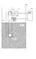
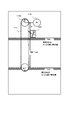
図1は本発明の異種液体検知システム100全体の構成を模式的に示した図である。図2は無限軌道式ベルト装置110の構成を示した図、図3はスクレーパー120とセンサ130の構成を示す図である。各図に示した各構成要素の形状は一例であり、本発明の異種液体検知システム100は多様な形状に対応できることは前述の通りである。
FIG. 1 is a diagram schematically showing the entire configuration of a different
実施例1の構成例において、異種液体検知システム100は、無限軌道式ベルト装置110、スクレーパー120、センサ130、制御部140を備えた構成となっている。タンク200内には正常液体として水210が貯蔵されている。
In the configuration example of the first embodiment, the different
無限軌道式ベルト装置110は、図1に示すように、液面の喫水線の下方と上方と間を結ぶ無限軌道で回転するようにタンク200内に取り付けられており、ベルト111、プーリー112a,112b、モーター113、その他回転駆動に必要な機構系や制御系を備えたものとなっている。制御系がモーター113を駆動させることによりプーリー112aを回転させ、ベルト111がプーリー112a,112b間を無限軌道にて回転する。
As shown in FIG. 1, the endless
例えば、タンク200の内壁面にフランジ(図示せず)が設けられており、モーター113が取付けられている。モーター113の回転軸にプーリー112aが嵌め込まれて固定されている。モーター113には駆動に必要なケーブル類や電子回路基板(図示せず)が設けられ、更に、モーターの回転部はカバー(図示せず)に覆われ、外部からの緩衝に対して保護されている。
For example, a flange (not shown) is provided on the inner wall surface of the
ここで、ベルト111の長さは、適用するタンク200により適切に選択することが好ましいが、図2に示すように、タンク200の中での通常想定している貯蔵水の一番低い状態の喫水線(Low)よりもプーリー112bが低い位置に取り付けられ、タンク200の中での通常想定している貯蔵水の一番高い状態の喫水線(High)よりもプーリー112aおよびセンサ130が高い位置に取り付けられる必要があるため、プーリー112aとセンサ130下面までの距離をSとすると、プーリー112aとプーリー112bの径Rとすると、ベルト111の長さLは2×(High−Low+S+2R)よりも大きいものとすれば良い。プーリー112a,プーリー112bの各々の取り付け位置も前述のとおり、プーリー112bはタンク200の中での通常想定している貯蔵水の一番低い状態の喫水線(Low)よりも低い位置に取り付け、プーリー112aおよびセンサ130はタンク200の中での通常想定している貯蔵水の一番高い状態の喫水線(High)よりも高い位置に取り付ける。
Here, the length of the
ベルト111の素材は限定されないが、もし、その表面が高い撥水性の素材であれば水や混入した異種液体を上方に上げることができないので、ある程度の親水性や表面摩擦がある素材を選び、表面摩擦がでるように表面加工を施しておくことが好ましい。素材としては、ゴムベルト、金属ベルトなどがある。
The material of the
ベルト111の張り方であるが、たわんでいる状態では後述するようにスクレーパー112による液体の掻き落としには不向きであるため、たわまない程度のテンションにてベルト111を張っておく。ここで、下方のプーリー112bの取り付け方法であるが、以下の2通りの方法がある。
Although the
第1の方法は、プーリー112bの回転軸を何らかの機構系を介してタンク200の内壁面に機械的に取り付けるものである。この方法によれば、プーリー112bの取り付け位置は固定され、当該位置がタンク200の中での通常想定している貯蔵水の一番低い状態の喫水線(Low)よりも低い位置であれば、異種液体検知システムの稼動において支障は生じない。
The first method is to mechanically attach the rotating shaft of the
第2の方法は、プーリー112bの重量とガイド(図示せず)により、ベルト111に対して常に下方向に力がかかる構造とする方法である。つまり、ベルト111には常に下方向の一定のテンションがかけられて鉛直下方に向けてたわむことなく引っ張られている。尚、ベルト111の長さLが上記のように2×(High−Low+S+2R)よりも大きいものに調整されておれば、プーリー112bは常に液体の喫水線の下となり、ベルト111は無限軌道を移動する中で、液面の喫水線近くの液体を表面張力およびベルト111との間の表面摩擦により上に引き上げることができる。
The second method is a method in which a force is always applied downward to the
次に、スクレーパー120は、図3に示すように、無限軌道式ベルト装置110のベルト111面に対して歯121が当たるように配置されている。スクレーパー120の素材は剛性のある板片であれば良く、例えばプラスチック片で良い。
Next, as shown in FIG. 3, the
スクレーパー120のベルト111面に対する取り付け位置に関しては、この構成例では、図3に示すように、無限軌道式ベルト装置110のベルト111の無限軌道のうち、ベルト111の移動方向が上方から下方へ移動する経路中でタンク200の貯蔵水の液面の喫水線より上である。このようにベルト111の移動方向が上方から下方へ移動する経路中でスクレーパー120の歯121を当てることで、ベルト111面上にある液体をベルト111面から掻き落として分離しやすくなり、後述するセンサ130に導きやすくなる。
With respect to the mounting position of the
ここで、スクレーパー120のベルト111面に対する取り付け角度であるが、図3(b)に示すように、ベルト111面に対して対向するように角度Aをつけて配設することが好ましい。スクレーパー120はベルト111面上にある液体をベルト111面から掻き落とすものであるため、角度Aをつけてスクレーパー120の歯を当てると、直角に歯を当てるよりも掻き落としやすくなるからである。スクレーパー120の歯121により無限軌道式ベルト装置110のベルト111面から掻き落とされた液体は、センサ130に導かれてゆく。
Here, the angle of attachment of the
次に、センサ130は、導かれてきた液体が、正常液体である水210のみであるか、その他の油などの不純物である異種液体211が混入しているかを判別するものである。
センサ130は、図3に示すように、液体流路131、検知プレート132、発光部133、受光部134、その他電子回路(図示せず)を備えている。
Next, the
As shown in FIG. 3, the
液体流路131は、スクレーパー120で掻き落とされた液体を受け取って検知プレート132上を通過させてタンク内に還流させる液体の流路である。
The
検知プレート132は、透光性を有する板材であり、例えば透明なガラスや透明なプラスチックなどで形成されている。液体流路131の一部として組み込まれ、液体流路131を流れる液体が検知プレート132上を通過するように配設されている。
The
発光部133は、白色LED素子などの発光素子を備えたものである。
受光部134は、受光した光のRGB色比率を捉える受光素子を備えたものである。
発光部133および受光部134は、検知プレート132を挟んで対向するように配設され、発光部133から発射された光が受光部134で直接受光されるように調整されている。図3の例では発光部133と受光部134の両者を結ぶ線が検知プレート132に対して直角に取り付けられている。
The
The
The
ここで、図3では、発光部133が下、受光部134が上に配設されているが、発光部133が上、受光部134が下に配設されていても良い。発光部133が下、受光部134が上に配設されている場合、作業員が船舶内燃機の冷却水清水タンク内を覗いて異種液体検知システム100を目視する場合に作業員が発光部133の発光を確認しやすいというメリットがある。
In FIG. 3, the
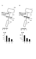
図4は検知プレート132上の液体による受光部133で受光される色の色比率の変化を検出する原理を説明する図である。
図4(a)は、油などの異種液体が混入せずに水のみの液体210が検知プレート132上に存在している場合に、センサ130で捉えた光のRGBの色比率の例を示す図である。この例では水のみの液体210を透過し、受光部134で受光された光に含まれるR:G:Bの色比率は8:5:3であるとする。なお、検知プレート132が透明なガラスなどの素材であれば受光した光のRGBの色比率には影響を与えない。
FIG. 4 is a diagram for explaining the principle of detecting the change in the color ratio of the color received by the
FIG. 4A shows an example of RGB color ratios of light captured by the
次に、図4(b)は、油などの異種液体211が混入し、その異種液体211が無限軌道式ベルト装置110により上方へ上げられ、スクレーパー120で掻き落とされ、センサ130の液体流路131から検知プレート132上に異種液体211が導かれた状態である。検知プレート132上には油などの異種液体211のみ、または、水210に加えて異種液体211が混在してその比重に応じて水分の上に油膜などの液膜を張るか、水分の下に油層などの液層を形成している。この状態において、異種液体211を透過し、受光部134で受光された光に含まれるR:G:Bの色比率は8.5:4.5:3であるとする。そのため、センサ130において、図4(a)で受光される光のR:G:Bの色比率は8:5:3であったものが、図4(b)で受光される光のR:G:Bの色比率が8.5:4.5:3に変化していることが検知される。
Next, FIG. 4B shows a case where a
センサ130は、受光される光のRGB色比率が変化したことを検出すれば、検知プレート132上の液体に水210とは異なる異種液体211が混入したと判別できる。
If the
次に、本発明の異種液体検知システムの動作を順を追って簡単にまとめておく。
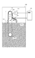
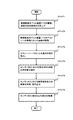
図5は本発明の異種液体検知システムの動作の流れを分かりやすく示す図である。図6は、本発明の異種液体検知システム100の動作の流れを簡単に示したフローチャートである。
Next, the operations of the different liquid detection system of the present invention will be briefly summarized in order.
FIG. 5 is a diagram showing the flow of operation of the foreign liquid detection system of the present invention in an easily understandable manner. FIG. 6 is a flowchart simply showing the flow of operation of the foreign
(動作の流れ1)
[無限軌道式ベルト装置110の駆動、液面付近の液体の引き上げ]
モーター113を作動すると、プーリー112aが回転を開始し、それに伴いベルト111が図7の矢印1の方向に沿って無限軌道の回転を開始する。この時、ベルト111のうちタンク200内の水面付近において下方(水面下)から上方(水面上)へ移動するベルト111により表面張力で水面の液分がベルト面にのったまま矢印方向へ引き上げられる。
(Operation flow 1)
[Driving the endless track
When the
(動作の流れ2)
[無限軌道式ベルト装置110のベルト移動にのった液体の移動]
無限軌道式ベルト装置110のベルト移動は無限軌道で回転を続け、タンク200内の水面付近において引き上げられた液分がベルト面にのったまま上方への移動を続ける。やがて無限軌道式ベルト装置110のベルト移動はプーリー112aにより折り返され、ベルト111の移動方向が矢印2の下向き方向へ反転する。
(Operation flow 2)
[Movement of liquid along belt movement of endless track type belt device 110]
The belt movement of the endless track
(動作の流れ3)
[スクレーパー120による液分の掻き落とし]
無限軌道式ベルト装置110のベルト移動を続けるとやがてスクレーパー120が配設されている箇所に至る。当該個所においてスクレーパー120の歯121がベルト111の表面と当接しており、表面張力によりベルト面に残留している液分を掻き落とす。
液分はベルト111からスクレーパー120を介して矢印3の方向に流れてゆく。
(Operation flow 3)
[Scraping off liquid with scraper 120]
If the belt movement of the endless track
The liquid flows from the
(動作の流れ4)
[センサ130における液分の屈折率の変化検出]
液分が矢印3の流れに沿って移動すると、液分は検知プレート132上を通過する。検知プレート132に対して発光部133から光が発射されており、当該照射光は、検知プレート132および液分を介して受光部134において受光される。この際、水210とは異なる異種液体211が検知プレート132上を通過すると、受光部132で受光される光のRGBの色比率が変化し、センサ130においてRGBの色比率の変化が検出される。
(Operation flow 4)
[Detection of change in refractive index of liquid in sensor 130]
When the liquid component moves along the flow of the
(動作の流れ5)
[センサ130における異種液体混入の有無の判別、信号出力]
センサ130は、受光された光のRGBの色比率の変化を検出しなければ異種液体211の混入はないと判別し、受光された光のRGBの色比率の変化を検出すると異種液体211の混入があったものと判別する。その後、異種液体検出システム100は制御部(図示せず)から異種液体混入判別信号を出力する。
(Operation flow 5)
[Determination of presence / absence of mixed liquid in
If the
(動作の流れ6)
[センサ130に取り込んだ液分の循環]
センサ130に取り込んで検知プレート132面で異種液体の混入検知に用いられた液分はそのまま矢印4の流れに沿ってタンク200内の水面へ戻される。
(Operation flow 6)
[Circulation of liquid taken into sensor 130]
The liquid component taken into the
実施例2の異種液体検知システム100aとして、センサ部130aで用いるセンサとして光の屈折率の変化を検出するタイプのセンサを用いた構成例を示す。
実施例2の異種液体検知システム100aの各構成要素は、受光部134aを除き、実施例1の異種液体検知システム100の各構成要素と同様で良い。
A configuration example using a sensor of a type that detects a change in the refractive index of light as a sensor used in the sensor unit 130a is shown as the different liquid detection system 100a of the second embodiment.
Each component of the different type liquid detection system 100a of Example 2 may be the same as each component of the different type
受光部134aは、受光素子を複数並べ、発光素子から発射された光の屈折率が変化しても光を捉えることができる受光素子アレイを形成した構成となっている。受光素子アレイとなっていると屈折率の変化による光線のずれが検出しやすくなる。
発光部133および受光部134aは、検知プレート132を挟んで対向するように配設され、発光部133から発射された光が受光部134aで直接受光されるように調整されている。
The light receiving unit 134a has a configuration in which a plurality of light receiving elements are arranged and a light receiving element array that can capture light even if the refractive index of light emitted from the light emitting elements changes. If the light receiving element array is used, it becomes easy to detect the deviation of the light beam due to the change in the refractive index.
The
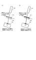
図7は検知プレート132上の液体による屈折率の変化を検出する原理を説明する図である。
ここで、図7に示すように、発光部133と受光部134aは、両者を結ぶ線が検知プレート132に対して斜めに取り付けられている。これは、本構成において、センサ130aが、異種液体の混入の判別として、検知プレート132上の液体による屈折率の変化を検出して判別するものであるからである。
FIG. 7 is a diagram for explaining the principle of detecting a change in the refractive index due to the liquid on the
Here, as shown in FIG. 7, the
図7(a)は、油などの異種液体が混入せずに水のみの液体210が検知プレート132上に存在している場合の光の屈折の様子を示す図である。センサ130aは、デフォルトの初期設定として、発光部133から発射された光が図7(a)のように屈折して受光部134aに受光されるものと調整されている。検知プレートの素材(ガラスやプラスチック)に応じた屈折率も加味して調整しておくことが好ましい。ここでは受光部134aには受光素子(1)から受光素子(7)までが並べられているものとする。
図7(a)に示すように、発光部133から発射された光は正常液体である水210の水面に対して斜めに当たって屈折し、境界面で角度が変化して受光部134aの所定位置に受光される。この例では、受光素子(3)に受光されている。
FIG. 7A is a diagram illustrating a state of light refraction when a liquid 210 containing only water is present on the
As shown in FIG. 7A, the light emitted from the
次に、図7(b)は、油などの異種液体211が混入し、その異種液体211が無限軌道式ベルト装置110により上方へ上げられ、スクレーパー120で掻き落とされ、センサ130aの液体流路131から検知プレート132上に異種液体211が導かれた状態である。検知プレート132上には油などの異種液体211のみ、または、水210に加えて異種液体211が混在してその比重に応じて水分の上に油膜などの液膜を張るか、水分の下に油層などの液層を形成している。この状態において、検知プレート132上の異種液体211は水210のみの屈折率とは異なる屈折率を示すようになる。そのため、発光部133から発射された光は液面に対して斜めに当たって屈折し、その境界面で角度が変化して受光部134aの所定位置に受光される。そのため、図7(b)に示すように、図7(a)とは屈折する角度が変化し、この例では、光線がより深い方向に屈折する。ここで、受光部134aが複数の受光素子を持つ受光素子アレイであれば、センサ130aは、図7(b)では、図7(a)で受光していた受光素子(3)とは異なる受光素子(4)によって光線が受光されたことを検出することができる。
Next, FIG. 7B shows that a
センサ130はa、光線が受光される受光素子が変化したことを検出すれば(この例では受光素子(3)から受光素子(4)へ変化した)、検知プレート132上の液体に水210とは異なる異種液体211が混入したと判別できる。
センサ部130aにより異種液体211の混入が検知された後の動作は、実施例1と同様で良い。
If the
The operation after the mixing of the
以上、実施例において説明した本発明の異種液体検知システムによれば、無限軌道式ベルトにより液面近くの少量の液分を確実に引き上げ、液面に多少の波などの揺らぎがあっても信頼性の高い異種液体混入検知を行うことができる。
また、装置の設置場所、環境温度、異種液体の混入を検知する液面の状態などの影響を受けにくく、検知信頼性が高く、装置の故障が少なく、高い耐久性を備えた異種液体検知システムおよび検知方法を提供することができる。
As described above, according to the heterogeneous liquid detection system of the present invention described in the embodiments, a small amount of liquid near the liquid surface is reliably pulled up by the endless track belt, and reliable even if there are some fluctuations in the liquid surface. It is possible to detect mixing of different types of liquids with high performance.
In addition, it is difficult to be affected by the installation location of the device, the environmental temperature, the condition of the liquid level that detects the presence of foreign liquids, etc., has high detection reliability, has few device failures, and has high durability. And a sensing method can be provided.
以上、本発明の異種液体検知システムの構成例における好ましい実施例を図示して説明してきたが、本発明の技術的範囲を逸脱することなく種々の変更が可能であることは理解されるであろう。 Although the preferred embodiments of the configuration examples of the different liquid detection system of the present invention have been illustrated and described above, it should be understood that various modifications can be made without departing from the technical scope of the present invention. Let's go.
本発明の異種液体検知システムは、人の目視による常時監視が困難な設備での異種液体の混入検知、例えば、船舶における船舶内燃機の冷却水清水タンクなどへの油等の異種液体の混入検知、工場設備・発電設備等の蒸気を用いた熱交換器の冷却水への油等の異種液体の混入検知、プール・浴場等での水・お湯への異種液体の混入検知、工場排水の清浄度監視などに適用できる。 The foreign liquid detection system of the present invention detects foreign liquid contamination in equipment that is difficult to monitor constantly by human eyes, for example, detection of foreign liquid contamination such as oil in a cooling water tank of a ship internal combustion engine in a ship, Detection of mixing of different liquids such as oil in the cooling water of heat exchangers using steam from factory facilities and power generation facilities, detection of mixing of different liquids in water and hot water at pools and bathhouses, etc. It can be applied to monitoring.
100 異種液体検知システム
110 無限軌道式ベルト装置
111 ベルト
120 スクレーパー
121 歯
130 センサ
131 液体流路
132 検知プレート
133 発光部
134 受光部
200 タンク
DESCRIPTION OF
Claims (9)
タンク内の検査対象液体の喫水線の下方と上方を結ぶ無限軌道で回転する無限軌道式ベルト装置と、
前記無限軌道に沿って移動する前記無限軌道式ベルト装置のベルト面に対して歯が当たるように配置されたスクレーパーと、
前記スクレーパーの歯により前記無限軌道式ベルト装置のベルト面から掻き落とされた液体を受け取って透光性を有する検知プレートを通過させてから前記タンク中に戻す液体流路と、前記検知プレートを挟んで対向する発光部および受光部とを備え、前記受光部で受光される信号変化を検出して前記正常液体とは異なる前記異種液体の混入を検知するセンサとを備えた異種液体検知システム。 A heterogeneous liquid detection system that detects the mixing of a heterogeneous liquid with respect to a normal liquid,
An endless track belt device that rotates on an endless track connecting the lower and upper sides of the waterline of the liquid to be inspected in the tank ;
A scraper disposed so that teeth contact the belt surface of the endless track belt device moving along the endless track;
A liquid channel that receives liquid scraped off from the belt surface of the endless track belt device by the teeth of the scraper, passes through a light-transmitting detection plate, and returns to the tank, and sandwiches the detection plate And a sensor for detecting a change in a signal received by the light receiving unit and detecting mixing of the different liquid different from the normal liquid.
検査対象液体の喫水線の下方と上方を結ぶ無限軌道で回転する無限軌道式ベルト装置により前記液面から液体を引き揚げ、
前記無限軌道に沿って移動する前記無限軌道式ベルト装置のベルト面に対して歯が当たるように配置されたスクレーパーにより前記液体を掻き落とし、
前記スクレーパーの歯により前記無限軌道式ベルト装置のベルト面から掻き落とされた液体を受け取って透光性を有する検知プレートを通過させ、前記検知プレートを挟んで対向する発光部から発射され受光部で受光される信号変化をセンサにより検出し、前記正常液体とは異なる前記異種液体の混入を検知する異種液体検知方法。 A foreign liquid detection method for detecting mixing of a different liquid with respect to a normal liquid,
The liquid is drawn from the liquid surface by an endless track belt device that rotates on an endless track connecting the lower and upper sides of the waterline of the liquid to be inspected,
The liquid is scraped off by a scraper arranged so that teeth hit the belt surface of the endless track type belt device that moves along the endless track.
The scraper teeth receive the liquid scraped off from the belt surface of the endless track belt device, pass the light-transmitting detection plate, and are emitted from the light-emitting portion facing the detection plate and received by the light-receiving portion. A heterogeneous liquid detection method for detecting a change in a received signal by a sensor and detecting mixing of the heterogeneous liquid different from the normal liquid.
Priority Applications (1)
| Application Number | Priority Date | Filing Date | Title |
|---|---|---|---|
| JP2010091200A JP5073774B2 (en) | 2010-04-12 | 2010-04-12 | Dissimilar liquid mixture detection device and method |
Applications Claiming Priority (1)
| Application Number | Priority Date | Filing Date | Title |
|---|---|---|---|
| JP2010091200A JP5073774B2 (en) | 2010-04-12 | 2010-04-12 | Dissimilar liquid mixture detection device and method |
Publications (2)
| Publication Number | Publication Date |
|---|---|
| JP2011220879A JP2011220879A (en) | 2011-11-04 |
| JP5073774B2 true JP5073774B2 (en) | 2012-11-14 |
Family
ID=45038045
Family Applications (1)
| Application Number | Title | Priority Date | Filing Date |
|---|---|---|---|
| JP2010091200A Expired - Fee Related JP5073774B2 (en) | 2010-04-12 | 2010-04-12 | Dissimilar liquid mixture detection device and method |
Country Status (1)
| Country | Link |
|---|---|
| JP (1) | JP5073774B2 (en) |
Families Citing this family (1)
| Publication number | Priority date | Publication date | Assignee | Title |
|---|---|---|---|---|
| WO2022044162A1 (en) | 2020-08-26 | 2022-03-03 | 三菱電機株式会社 | Detection device and detection method |
Family Cites Families (1)
| Publication number | Priority date | Publication date | Assignee | Title |
|---|---|---|---|---|
| JPS524073Y2 (en) * | 1971-06-15 | 1977-01-27 |
-
2010
- 2010-04-12 JP JP2010091200A patent/JP5073774B2/en not_active Expired - Fee Related
Also Published As
| Publication number | Publication date |
|---|---|
| JP2011220879A (en) | 2011-11-04 |
Similar Documents
| Publication | Publication Date | Title |
|---|---|---|
| US8701746B2 (en) | Optically detected liquid depth information in a climate control unit | |
| KR101860088B1 (en) | An apparatus for depth-measuring and monitoring an interface and a depth-measuring and monitoring method using the same | |
| KR102026340B1 (en) | Buoy type laser water gauge using a filter pipe | |
| JP5073774B2 (en) | Dissimilar liquid mixture detection device and method | |
| KR102026339B1 (en) | Buoy type laser water gauge | |
| JP2012037356A (en) | Fluorescence detector | |
| JPH0389097A (en) | Oil condition detector for marine propulsion unit | |
| KR101622171B1 (en) | Device monitoring water pollution level by analyzing water surfacecolor | |
| JP5184264B2 (en) | Leak sensor | |
| JP2009014660A (en) | Two-liquid leakage sensor and prism for the same | |
| JP4323538B2 (en) | Fuel property detection device | |
| JPH09138196A (en) | Liquid particle concentration detector | |
| US3885418A (en) | Method and apparatus for detecting the presence of an oil slick on a water surface | |
| KR20080048825A (en) | Water level measuring device | |
| JP2019025383A (en) | Weight automatic tensioning device and sludge scraper | |
| JPH0514209B2 (en) | ||
| KR100932686B1 (en) | Water tower pollution prevention facility with safety diagnosis function | |
| KR101913173B1 (en) | Contamination Measuring Device for Solar Panel Surface | |
| CN114863646B (en) | Air pollution early warning system based on atmospheric oxidizing conditions | |
| JP5149080B2 (en) | Leak sensor | |
| JP3346004B2 (en) | Liquid particle concentration detector | |
| KR101049946B1 (en) | Water level control device using total reflection | |
| ATE247733T1 (en) | FLOOD PREVENTION DEVICE FOR DISHWASHER OR WASHING MACHINE | |
| CN221506899U (en) | Water quality monitoring device based on stm32 | |
| CN119986604B (en) | Ultra-long distance infrared laser module support frame with vibration-resistant structure |
Legal Events
| Date | Code | Title | Description |
|---|---|---|---|
| A977 | Report on retrieval |
Free format text: JAPANESE INTERMEDIATE CODE: A971007 Effective date: 20120222 |
|
| A131 | Notification of reasons for refusal |
Free format text: JAPANESE INTERMEDIATE CODE: A131 Effective date: 20120313 |
|
| A521 | Written amendment |
Free format text: JAPANESE INTERMEDIATE CODE: A523 Effective date: 20120511 |
|
| TRDD | Decision of grant or rejection written | ||
| A01 | Written decision to grant a patent or to grant a registration (utility model) |
Free format text: JAPANESE INTERMEDIATE CODE: A01 Effective date: 20120814 |
|
| A01 | Written decision to grant a patent or to grant a registration (utility model) |
Free format text: JAPANESE INTERMEDIATE CODE: A01 |
|
| A61 | First payment of annual fees (during grant procedure) |
Free format text: JAPANESE INTERMEDIATE CODE: A61 Effective date: 20120822 |
|
| R150 | Certificate of patent or registration of utility model |
Ref document number: 5073774 Country of ref document: JP Free format text: JAPANESE INTERMEDIATE CODE: R150 Free format text: JAPANESE INTERMEDIATE CODE: R150 |
|
| FPAY | Renewal fee payment (event date is renewal date of database) |
Free format text: PAYMENT UNTIL: 20150831 Year of fee payment: 3 |
|
| R250 | Receipt of annual fees |
Free format text: JAPANESE INTERMEDIATE CODE: R250 |
|
| R250 | Receipt of annual fees |
Free format text: JAPANESE INTERMEDIATE CODE: R250 |
|
| LAPS | Cancellation because of no payment of annual fees |