JP5073764B2 - Gear transmission lubrication equipment - Google Patents
Gear transmission lubrication equipment Download PDFInfo
- Publication number
- JP5073764B2 JP5073764B2 JP2010015005A JP2010015005A JP5073764B2 JP 5073764 B2 JP5073764 B2 JP 5073764B2 JP 2010015005 A JP2010015005 A JP 2010015005A JP 2010015005 A JP2010015005 A JP 2010015005A JP 5073764 B2 JP5073764 B2 JP 5073764B2
- Authority
- JP
- Japan
- Prior art keywords
- gear
- tooth
- lubricating oil
- oil supply
- tooth bottom
- Prior art date
- Legal status (The legal status is an assumption and is not a legal conclusion. Google has not performed a legal analysis and makes no representation as to the accuracy of the status listed.)
- Active
Links
Images
Landscapes
- Gear Transmission (AREA)
- Gears, Cams (AREA)
- General Details Of Gearings (AREA)
Description
本発明は、潤滑対象となる歯車に噛み合う歯車を備えた歯車伝達潤滑機器に関する。 The present invention relates to a gear transmission lubrication device including a gear meshing with a gear to be lubricated.
従来、潤滑剤トランスファピニオンと、この潤滑剤トランスファピニオンと噛み合う潤滑対象歯車とを備えた歯車伝達潤滑機器が知られている(例えば、特許文献1参照)。この歯車伝達潤滑機器では、潤滑剤トランスファピニオンの内部から、潤滑剤トランスファピニオンの歯部と潤滑対象歯車の歯部との接触部分に向けて、潤滑油が供給される。 Conventionally, a gear transmission lubrication device including a lubricant transfer pinion and a gear to be lubricated that meshes with the lubricant transfer pinion is known (for example, see Patent Document 1). In this gear transmission lubrication device, lubricating oil is supplied from the inside of the lubricant transfer pinion toward the contact portion between the tooth portion of the lubricant transfer pinion and the tooth portion of the gear to be lubricated.
従って、潤滑剤トランスファピニオンの内部から供給された潤滑油は、潤滑剤トランスファピニオンの歯部と潤滑対象歯車の歯部との接触部分から、潤滑対象歯車の隣り合う歯部間に形成された歯底部に向かってほとんど流れることはない。このため、潤滑剤トランスファピニオンの内部から供給された潤滑油が、潤滑対象歯車の歯底部に供給されないという問題があった。 Therefore, the lubricating oil supplied from the inside of the lubricant transfer pinion is generated from the contact portion between the tooth portion of the lubricant transfer pinion and the tooth portion of the gear to be lubricated, between the adjacent tooth portions of the gear to be lubricated. There is almost no flow towards the bottom. For this reason, there was a problem that the lubricating oil supplied from the inside of the lubricant transfer pinion was not supplied to the tooth bottom portion of the gear to be lubricated.
本発明の目的は、第1歯車と噛み合うように配置された第2歯車の歯底部に対して潤滑油を確実に供給可能な歯車伝達潤滑機器を提供することである。 An object of the present invention is to provide a gear transmission lubrication device that can reliably supply lubricating oil to a tooth bottom portion of a second gear arranged to mesh with a first gear.
第1の発明に係る歯車伝達潤滑機器は、支持軸に回転可能に支持され、複数の第1歯部を有する第1歯車と、前記第1歯車と噛み合うように配置され、複数の第2歯部を有する第2歯車と、前記第2歯車と噛み合うように配置され、複数の第3歯部を有する第3歯車と、前記第1歯車の少なくとも一端に配置され、側面視で前記第1歯部間において前記第1歯底部より径方向外側に配置された部分を有する板状部材と、前記支持軸に形成され、前記支持軸内の潤滑油の流路から前記支持軸の外周面に向かった給油孔と、前記第1歯車に形成され、前記給油孔に接続可能であって且つ前記第1歯部間の第1歯底部に向かった給油経路とを備え、前記第1歯車の前記第1歯部と前記第2歯車の前記第2歯部とが噛み合っている部分において、前記支持軸の給油孔と、前記第2歯部の歯先部分に対向した前記第1歯底部に向かった給油経路とが一致するように構成され、前記支持軸の給油孔と前記第1歯車の給油経路とが一致したときにだけ、前記第1歯底部に対して潤滑油を供給する。 A gear transmission lubrication device according to a first aspect of the present invention is rotatably supported on a support shaft, arranged to mesh with a first gear having a plurality of first teeth, and a plurality of second teeth. A second gear having a portion, a third gear arranged to mesh with the second gear, and having a plurality of third teeth, and at least one end of the first gear, and the first tooth in a side view A plate-like member having a portion disposed radially outside the first tooth bottom portion between the portions, and formed on the support shaft, from a lubricating oil flow path in the support shaft toward the outer peripheral surface of the support shaft. And an oil supply path formed in the first gear, connectable to the oil supply hole, and directed to a first tooth bottom portion between the first tooth portions, the first gear of the first gear. In a portion where one tooth portion and the second tooth portion of the second gear mesh with each other, An oil supply hole of the holding shaft and an oil supply path toward the first tooth bottom part facing the tooth tip part of the second tooth part coincide with each other, and the oil supply hole of the support shaft and the first gear Only when the oil supply path matches, the lubricating oil is supplied to the first tooth bottom portion.
この歯車伝達潤滑機器では、第1歯車において隣り合う第1歯部間に形成された第1歯底部に潤滑油が供給されることによって、第1歯底部に潤滑油を溜め込むことができる。そして、第1歯車の第1歯底部に溜め込まれた潤滑油は、第1歯車と第2歯車とが噛み合いつつ回転する際に、第2歯車の第2歯部によって、第2歯車の第2歯底部に向かって押し出される。従って、第1歯車の第1歯底部に溜め込まれた潤滑油を第2歯車の第2歯底部に移動させることによって、第2歯車において隣り合う第2歯部間に形成された第2歯底部に対して潤滑油を供給することができる。
また、支持軸の流路と第1歯車の給油経路とが一致したときにだけ、第1歯車に向けて潤滑油の供給を行うことができるので、常に潤滑油の供給を行う場合と比べて、潤滑油の供給量を削減でき、歯車伝達潤滑機器のメンテナンスに要するコストを削減できる。
In this gear transmission lubrication device, the lubricating oil can be stored in the first tooth bottom portion by supplying the lubricating oil to the first tooth bottom portion formed between the adjacent first tooth portions in the first gear. The lubricating oil accumulated in the first tooth bottom portion of the first gear is rotated by the second tooth portion of the second gear by the second tooth portion of the second gear when the first gear and the second gear rotate while meshing with each other. It is pushed out toward the bottom of the tooth. Accordingly, by moving the lubricating oil accumulated in the first tooth bottom portion of the first gear to the second tooth bottom portion of the second gear, the second tooth bottom portion formed between adjacent second tooth portions in the second gear. Lubricating oil can be supplied.
Further, since the lubricating oil can be supplied toward the first gear only when the flow path of the support shaft and the oil supply path of the first gear coincide with each other, compared to the case where the lubricating oil is always supplied. The amount of lubricating oil supplied can be reduced, and the cost required for maintenance of gear transmission lubrication equipment can be reduced.
この歯車伝達潤滑機器では、板状部材が、側面視で、第1歯部間において第1歯底部より径方向外側に配置された部分を有していることにより、この径方向外側に配置された部分が障壁となって、第1歯車の第1歯底部に溜め込まれた潤滑油が第1歯車の一端から漏れ出ることを防止できる。 In this gear transmission lubrication device, the plate-like member is arranged on the outer side in the radial direction by having a portion arranged on the outer side in the radial direction from the first tooth bottom part between the first tooth parts in a side view. Therefore, the lubricating oil accumulated in the first tooth bottom portion of the first gear can be prevented from leaking from one end of the first gear.
この歯車伝達潤滑機器では、第1歯車の第1歯底部に溜め込まれた潤滑油が第2歯車の第2歯底部に移動するのと同様にして、第2歯車の第2歯底部に溜め込まれた潤滑油が、第2歯車と第3歯車とが噛み合いつつ回転する際に、第3歯車の第3歯部によって、第3歯車の第3歯底部に向かって押し出される。よって、第2歯車の第2歯底部に溜め込まれた潤滑油を第3歯車の第3歯底部に向かって移動させることができる。従って、第3歯車の第3歯部の歯先部分、根元部分、及び、第3歯車において隣り合う第3歯部間に形成された第3歯底部に対して潤滑油を供給することができる。 In this gear transmission lubrication device, the lubricating oil accumulated in the first tooth bottom portion of the first gear is accumulated in the second tooth bottom portion of the second gear in the same manner as the lubricating oil moves to the second tooth bottom portion of the second gear. When the second and third gears rotate while meshing with each other, the lubricating oil is pushed out toward the third tooth bottom portion of the third gear by the third tooth portion of the third gear. Therefore, the lubricating oil accumulated in the second tooth bottom portion of the second gear can be moved toward the third tooth bottom portion of the third gear. Accordingly, the lubricating oil can be supplied to the tip portion, the root portion, and the third tooth bottom portion formed between the adjacent third tooth portions of the third gear in the third gear portion. .
以上の説明に述べたように、本発明によれば、以下の効果が得られる。 As described above, according to the present invention, the following effects can be obtained.
第1の発明では、第1歯車において隣り合う第1歯部間に形成された第1歯底部に潤滑油が供給されることによって、第1歯底部に潤滑油を溜め込むことができる。そして、第1歯車の第1歯底部に溜め込まれた潤滑油は、第1歯車と第2歯車とが噛み合いつつ回転する際に、第2歯車の第2歯部によって、第2歯車の第2歯底部に向かって押し出される。従って、第1歯車の第1歯底部に溜め込まれた潤滑油を第2歯車の第2歯底部に移動させることによって、第2歯車において隣り合う第2歯部間に形成された第2歯底部に対して潤滑油を供給することができる。
また、支持軸の流路と第1歯車の給油経路とが一致したときにだけ、第1歯車1に向けて潤滑油の供給を行うことができるので、常に潤滑油の供給を行う場合と比べて、潤滑油の供給量を削減でき、歯車伝達潤滑機器のメンテナンスに要するコストを削減できる。
In the first invention, the lubricating oil can be stored in the first tooth bottom portion by supplying the lubricating oil to the first tooth bottom portion formed between the adjacent first tooth portions in the first gear. The lubricating oil accumulated in the first tooth bottom portion of the first gear is rotated by the second tooth portion of the second gear by the second tooth portion of the second gear when the first gear and the second gear rotate while meshing with each other. It is pushed out toward the bottom of the tooth. Accordingly, by moving the lubricating oil accumulated in the first tooth bottom portion of the first gear to the second tooth bottom portion of the second gear, the second tooth bottom portion formed between adjacent second tooth portions in the second gear. Lubricating oil can be supplied.
Further, since the lubricating oil can be supplied toward the
第1の発明では、板状部材が、側面視で、第1歯部間において第1歯底部より径方向外側に配置された部分を有していることにより、この径方向外側に配置された部分が障壁となって、第1歯車の第1歯底部に溜め込まれた潤滑油が第1歯車の一端から漏れ出ることを防止できる。 In 1st invention, the plate-shaped member is arrange | positioned in this radial direction outer side by having the part arrange | positioned in the radial direction outer side from the 1st tooth bottom part between 1st tooth parts by the side view. The portion serves as a barrier, and the lubricating oil accumulated in the first tooth bottom portion of the first gear can be prevented from leaking from one end of the first gear.
第1の発明では、第1歯車の第1歯底部に溜め込まれた潤滑油が第2歯車の第2歯底部に移動するのと同様にして、第2歯車の第2歯底部に溜め込まれた潤滑油が、第2歯車と第3歯車とが噛み合いつつ回転する際に、第3歯車の第3歯部によって、第3歯車の第3歯底部に向かって押し出される。よって、第2歯車の第2歯底部に溜め込まれた潤滑油を第3歯車の第3歯底部に向かって移動させることができる。従って、第3歯車の第3歯部の歯先部分、根元部分、及び、第3歯車において隣り合う第3歯部間に形成された第3歯底部に対して潤滑油を供給することができる。 In the first invention, the lubricating oil accumulated in the first tooth bottom of the first gear is accumulated in the second tooth bottom of the second gear in the same manner as the lubricating oil moves to the second tooth bottom of the second gear. When the lubricating oil rotates while meshing with the second gear and the third gear, the lubricating oil is pushed out toward the third tooth bottom of the third gear by the third tooth of the third gear. Therefore, the lubricating oil accumulated in the second tooth bottom portion of the second gear can be moved toward the third tooth bottom portion of the third gear. Accordingly, the lubricating oil can be supplied to the tip portion, the root portion, and the third tooth bottom portion formed between the adjacent third tooth portions of the third gear in the third gear portion. .
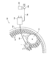
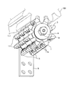
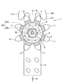
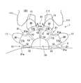
以下、図面に基づいて、本発明の一実施形態に係る歯車伝達潤滑機器について説明する。図1は、本実施形態に係る歯車伝達潤滑機器の全体構成を示した模式図である。図2は、図1の第1歯車の外観斜視図である。図3は、図1の第1歯車の構造を示した側面視図である。図4は、図3の一部の拡大図である。図5は、図3のA−A線の矢視断面図である。 Hereinafter, a gear transmission lubrication device according to an embodiment of the present invention will be described based on the drawings. FIG. 1 is a schematic diagram showing an overall configuration of a gear transmission lubrication device according to the present embodiment. FIG. 2 is an external perspective view of the first gear of FIG. FIG. 3 is a side view showing the structure of the first gear of FIG. FIG. 4 is an enlarged view of a part of FIG. 5 is a cross-sectional view taken along line AA in FIG.
<歯車伝達潤滑機器>
図1に示すように、歯車伝達潤滑機器100は、8個の第1歯部11を有する第1歯車1と、この第1歯車1と噛み合うように配置され、18個の第2歯部111を有する第2歯車101と、この第2歯車101と噛み合うように配置され、複数の第3歯部121を有する第3歯車102と、分配弁103と、給油ポンプ104とを備えている。また、本実施形態では、第1歯車1の主な材質には、NBR(ニトリルゴム)とPVC(ポリ塩化ビニル)が用いられている。また、第3歯車102は、風力発電用風車の駆動機構に用いられる。
<Gear transmission lubrication equipment>
As shown in FIG. 1, the gear
図1において、第2歯車101に連結された駆動モータ(図示せず)が第2歯車101を回転させると、この第2歯車101と噛み合う第1歯車1及び第3歯車102に動力が伝達されて、第1歯車1及び第3歯車102が回転する。
In FIG. 1, when a drive motor (not shown) connected to the
また、分配弁103は、図1に示すように、給油ホース105を介して第1歯車1に接続されると共に、給油ホース106を介して給油ポンプ104と接続されている。また、給油ポンプ104には、グリース等の潤滑油が貯留されたタンク107が接続されている。これにより、分配弁103には、給油ポンプ104の駆動によって給油ホース106を介して潤滑油が供給される。そして、分配弁103に供給された潤滑油は、供給量が調整された後に、給油ホース105を介して第1歯車1に供給される。
As shown in FIG. 1, the
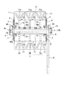
図2〜図5に示すように、歯車伝達潤滑機器100は、第1歯車1を回転可能に支持する支持軸2と、一対の板状部材3と、一対の補強板4と、一対の固定部材5と、アーム部6と、一対のリング部材7とを有している。なお、図4では、図面を簡略化するために、固定部材5の図示を省略している。
As shown in FIGS. 2 to 5, the gear
<第1歯車>
図5に示すように、第1歯車1は、同一の形状を有する3つの分割部材1A〜1Cで構成されている。各分割部材1A〜1Cは、図3及び図5に示すように、第1歯車1の一端1aから他端1bに向かって軸方向に貫通するように形成され且つ支持軸2が介挿された介挿孔10と、8つの第1歯部11と、隣り合う第1歯部11間に形成された8つの第1歯底部12と、各第1歯底部12に対して潤滑油を供給するための8つの給油経路径路13とを有している。本発明において、第1歯底部12は、図4に示すように、歯底円C(図中の一点鎖線で示した円弧)の円周上にある一部分を意味する。
<First gear>
As shown in FIG. 5, the
また、図5に示すように、各第1歯部11は、正面視において、第1歯車1の軸方向に沿う全長にわたって形成されている。また、図5に示すように、各分割部材1A〜1Cの各第1歯部11の側面には、3つの楕円形状を有するガイド溝11aが形成されている。図2に示すように、各ガイド溝11aは、周方向に窪んだ凹形状を有している。また、図5に示すように、各ガイド溝11aは、給油経路13の径方向外側の端部から放射状に広がるようにして形成されており、第1歯底部12に溜め込まれた潤滑油を第2歯車101に案内するために形成されている。図3に示すように、各給油経路13は、後述する支持軸2内の潤滑油の流路20から各第1歯底部12に向かって延在するように形成されており、この給油経路13を介して第1歯底部12に潤滑油が供給される。図5に示すように、この給油経路13は、各分割部材1A〜1Cの合わせ面とは異なる位置に形成されている。
Further, as shown in FIG. 5, each
<支持軸>
図5に示すように、支持軸2には、潤滑油の流路20が形成されている。この流路20は、給油孔20aと、給油孔20bと、切り欠き20cとで構成されている。図5に示すように、給油孔20aは、支持軸2の一端側から他端側に向かって軸方向に貫通するように形成されている。この給油孔20aは、第1歯車1の一端1a側において、固定部材5及びアーム部6に形成された貫通孔を介して給油ホース105の一端と接続されており、分配弁103から潤滑油の供給を受けるための給油孔として設けられている。また、図5に示すように、給油孔20aの他端1b側は、給油孔20aに供給された潤滑油の漏れを防ぐための固定部材5が固定されている。給油孔20bは、給油孔20aから支持軸2の外周面に向けて軸方向と鉛直方向に貫通するように形成されている。この給油孔20bは、第1歯車1の軸方向に沿って所定の間隔をおいて3つ形成されている。また、図5に示すように、切り欠き20cは、各給油孔20bの径方向外側の端部において3つ形成されている。
<Support shaft>
As shown in FIG. 5, a lubricating
<板状部材>
図5に示すように、板状部材3は、第1歯車1の両端に配置されている。図3及び図4に示すように、この板状部材3は、第1歯部11間において第1歯底部12より径方向外側に配置された部分を有している。つまり、板状部材3の外周部には、図4に示すように、各第1歯部11の根元部分11bを覆う凸部30と、各第1歯底部12を覆う凹部31とが、周方向に沿って交互に形成されている。そして、図4に示すように、各凹部31の奥部31aは、側面視において、各第1歯底部12よりも径方向外側に配置されている。また、本発明において、根元部分11bとは、第1歯車1の第1歯部11と第2歯車101の第2歯部111とが噛み合う際の接触部Sよりも径方向の内側にある部分を意味し、歯先部分とは、この接触部Sよりも径方向の外側にある部分を意味する。また、本実施形態では、板状部材3の材質にはゴムが用いられている。
<Plate-shaped member>
As shown in FIG. 5, the plate-
<補強板>
図5に示すように、補強板4は、板状部材3を挟持するようにして第1歯車1の両端に配置されている。また、図5に示すように、各補強板4の内側には、第1歯車1の周方向に沿って、密封用のリング部材7が介装された切り欠き40が形成されている。また、本実施形態では、補強板4の材質には鉄(Fe)が用いられている。
<Reinforcing plate>
As shown in FIG. 5, the reinforcing
<歯車伝達潤滑機器の給油動作>
図3及び図5に示すように、給油径路13の径方向内側の端部は、第1歯車1と第2歯車101とが噛み合いつつ第1歯車1が支持軸2に対して所定の角度だけ回転した場合に、支持軸2の切り欠き20cと一致するように形成されている。これにより、支持軸2の給油孔20a及び給油孔20bと、第1歯車1の給油径路13とを介して、この給油径路13の径方向外側の端部と連通する第1歯底部12に潤滑油が供給され、この潤滑油が第1歯底部12に溜め込まれる。また、本実施形態では、支持軸2の流路20と第1歯車1の給油径路13とが一致したときにだけ、給油ホース105を介して分配弁103から第1歯車1に向けた潤滑油の供給が行われる。
<Lubrication operation of gear transmission lubrication equipment>
As shown in FIGS. 3 and 5, the radially inner end of the
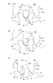
図6(a)〜(c)は、歯車伝達潤滑機器の給油動作を示した説明図である。なお、図6(a)〜(c)では、図面を簡略化するために、板状部材3、補強板4及び固定部材5の図示を省略している。図6(a)では、第1歯車1の第1歯部11と、第2歯車101の第2歯部111とが噛み合っている。この状態では、上述したように、第1歯車1の給油径路13と支持軸2の流路20とが一致しており、第1歯底部12に潤滑油(図中の斜線でハッチングした部分)が溜め込まれる。
6 (a) to 6 (c) are explanatory views showing the oil supply operation of the gear transmission lubrication device. In FIGS. 6A to 6C, the plate-
図6(b)は、図6(a)の状態から、第1歯車1を支持軸2に対して所定の角度だけ回転させた状態を示している。この状態では、第2歯車101の第2歯部111の歯先部分によって、第1歯車1の第1歯底部12に溜め込まれていた潤滑油(図中の斜線でハッチングした部分)が第2歯車101の第2歯底部112に向かって押し出される。そして、押し出された潤滑油は、図6(c)に示すように、第2歯車101の第2歯底部112に溜め込まれる(図中の斜線でハッチングした部分)。さらに、第2歯底部112に溜め込まれた潤滑油は、図示しない第3歯車102の第3歯部の歯先部分によって、図示しない第3歯部の第3歯底部に向かって押し出される。よって、第2歯車101の第2歯底部112に溜め込まれた潤滑油を第3歯車の第3歯底部に向かって移動させることができる。従って、第3歯車102の第3歯部の歯先部分、根元部分、及び、第3歯車102において隣り合う第3歯部間に形成された第3歯底部に対して潤滑油を供給することができる。
FIG. 6B shows a state in which the
[本実施形態の歯車伝達潤滑機器の特徴]
以上、本実施形態の歯車伝達潤滑機器では、第1歯車1において隣り合う第1歯部11間に形成された第1歯底部12に潤滑油が供給されることによって、第1歯底部12に潤滑油を溜め込むことができる。そして、第1歯車1の第1歯底部12に溜め込まれた潤滑油は、第1歯車1と第2歯車101とが噛み合いつつ回転する際に、第2歯車101の第2歯部111によって、第2歯車101の第2歯底部112に向かって押し出される。従って、第1歯車1の第1歯底部11に溜め込まれた潤滑油を第2歯車101の第2歯底部112に移動させることによって、第2歯車101において隣り合う第2歯部111間に形成された第2歯底部112に対して潤滑油を供給することができる。
[Features of gear transmission lubrication device of this embodiment]
As described above, in the gear transmission lubrication device of the present embodiment, the lubricating oil is supplied to the first
また、第1歯車1の第1歯底部12に溜め込まれた潤滑油は、第2歯車101の第2歯部111によって、第2歯車101の第2歯底部112に向かって押し出されるので、少量の潤滑油で、第2歯車101の第2歯底部112に潤滑油の油溜まり部を形成することができる。
Further, since the lubricating oil accumulated in the first
また、第1歯底部12に対して潤滑油が供給される給油径路13は、支持軸2内の潤滑油の流路20から第1歯底部12まで延在しているので、従来のように給油径路が支持軸2内の潤滑油の流路20から第1歯車1の第1歯部11まで延在している場合と比べて、潤滑油の供給径路の経路長を短くできる。従って、給油経路の形成に要する加工が従来よりも簡単になる。
Further, the
また、板状部材3が、側面視で、第1歯部11間において第1歯底部12より径方向外側に配置された部分を有していることにより、この径方向外側に配置された部分が障壁となって、第1歯車1の第1歯底部12に溜め込まれた潤滑油が第1歯車1の両端から漏れ出ることを防止できる。
Further, the plate-
また、第1歯車1の第1歯底部12に溜め込まれた潤滑油が第2歯車101の第2歯底部112に移動するのと同様にして、第2歯車101の第2歯底部112に溜め込まれた潤滑油が、第2歯車101と第3歯車102とが噛み合いつつ回転する際に、第3歯車102の第3歯部121によって、第3歯車102の第3歯底部に向かって押し出される。よって、第2歯車101の第2歯底部112に溜め込まれた潤滑油を第3歯車102の第3歯底部に向かって移動させることができる。従って、第3歯車102の第3歯部の歯先部分、根元部分、及び、第3歯車102において隣り合う第3歯部間に形成された第3歯底部に対して潤滑油を供給することができる。
Further, the lubricating oil stored in the first
また、支持軸2の流路20と第1歯車1の給油径路13とが一致したときにだけ、分配弁103から第1歯車1に向けて潤滑油の供給を行うことができるので、分配弁103から常に潤滑油の供給を行う場合と比べて、潤滑油の供給量を削減でき、歯車伝達潤滑機器100のメンテナンスに要するコストを削減できる。
Further, since the lubricating oil can be supplied from the
また、給油径路13を各分割部材1A〜1Cの合わせ面に形成したような場合では、硬くて粘りのある潤滑油が給油通路13を通過することにより、合わせ面が開いて、潤滑油が、相手方歯車である第2歯車101と噛み合っていないところも含めて第1歯車1の全体にわたって漏れ出てしまうという問題があるが、本実施形態では、給油径路13が各分割部材1A〜1Cの合わせ面と異なる位置に形成されているため、このような問題は生じない。
Further, in the case where the
以上、本発明の実施形態について図面に基づいて説明したが、具体的な構成は、これらの実施形態に限定されるものではないと考えられるべきである。本発明の範囲は、上記した実施形態の説明ではなく特許請求の範囲によって示され、さらに特許請求の範囲と均等の意味および範囲内でのすべての変更が含まれる。 As mentioned above, although embodiment of this invention was described based on drawing, it should be thought that a specific structure is not limited to these embodiment. The scope of the present invention is shown not by the above description of the embodiments but by the scope of claims for patent, and further includes all modifications within the meaning and scope equivalent to the scope of claims for patent.
上述した実施形態では、第1歯車1の主な材質にNBR(ニトリルゴム)とPVC(ポリ塩化ビニル)を用いる例について述べたが、本発明はこれに限らず、第1歯車1の材質は変更できる。
In the above-described embodiment, the example in which NBR (nitrile rubber) and PVC (polyvinyl chloride) are used as the main material of the
上述した実施形態では、板状部材3の材質にゴムを用いる例について述べたが、本発明はこれに限らず、板状部材3の材質は変更できる。
In the embodiment described above, an example in which rubber is used as the material of the plate-
上述した実施形態では、補強板4の材質に鉄(Fe)を用いる例について述べたが、本発明はこれに限らず、補強板4の材質は変更できる。
In the embodiment described above, an example in which iron (Fe) is used as the material of the reinforcing
上述した実施形態では、第1歯車1が8個の第1歯部11を有する例について述べたが、本発明はこれに限らず、第1歯車1が、7個以下、または、9個以上の第1歯部を有していてもよい。
In the above-described embodiment, the example in which the
上述した実施形態では、第2歯車101が18個の第2歯部111を有する例について述べたが、本発明はこれに限らず、第2歯車101が、17個以下、または、19個以上の第2歯部を有していてもよい。
In the above-described embodiment, the example in which the
上述した実施形態では、第3歯車102が風力発電用風車の駆動機構に用いられる例について述べたが、本発明はこれに限らず、第3歯車102が他の産業機械の駆動機構に用いられてもよい。
In the above-described embodiment, the example in which the
上述した実施形態では、各第1歯部11が、正面視において、第1歯車1の軸方向に沿う全長にわたって形成される例について述べたが、本発明はこれに限らず、各第1歯部11が、側面視において、第1歯車1の軸方向に沿う一部分に形成されてもよい。
In the above-described embodiment, the example in which each
上述した実施形態では、第1歯車1が3つの分割部材1A〜1Cで構成される例について述べたが、本発明はこれに限らず、第1歯車1が、2つ、または、4つ以上の分割部材で構成されてもよく、第1歯車1が一体の部材で構成されてもよい。
In the above-described embodiment, the example in which the
上述した実施形態では、板状部材3の凸部30によって、第1歯部11の根元部分11bのみが覆われる例について述べたが、本発明はこれに限らず、板状部材3の凸部30によって、第1歯部11の根元部分11bと、それより先端の部分とが覆われていてもよく、第1歯部11の全体が覆われてもよい。
In the above-described embodiment, the example in which only the
上述した実施形態では、板状部材3が第1歯車1の両端に配置される例について述べたが、本発明はこれに限らず、板状部材3が第1歯車1の一端1a側のみに配置されてもよく、板状部材3が第1歯車1の他端1b側のみに配置されてもよく、板状部材3が配置されていなくてもよい。
In the above-described embodiment, the example in which the plate-
上述した実施形態では、第1歯車1から第2歯車101を経由して第3歯車102に間接的に潤滑油を供給する例について述べたが、本発明はこれに限らず、歯車伝達潤滑機器において、第1歯車1と第3歯車102とが直接噛み合うように配置されており、第1歯車1から第3歯車102に直接的に潤滑油を供給してもよい。
In the above-described embodiment, the example in which the lubricating oil is indirectly supplied from the
上述した実施形態では、各分割部材1A〜1Cの各第1歯部11の側面に、3つの楕円形状を有するガイド溝11aが形成される例について述べたが、本発明はこれに限らず、各第1歯部11の側面に、2つ以下、または、4つ以上のガイド溝11aを形成してもよく、各第1歯部11の側面に、ガイド溝11aが形成されていなくてもよい。また、ガイド溝11aの形状は任意の形状に変更できる。
In embodiment mentioned above, although the example in which the
本発明を利用すれば、第1歯車と噛み合うように配置された第2歯車の歯底部に対して潤滑油を確実に供給可能な歯車伝達潤滑機器を得ることができる。 By using the present invention, it is possible to obtain a gear transmission lubrication device that can reliably supply lubricating oil to the tooth bottom portion of the second gear arranged so as to mesh with the first gear.
1 第1歯車
1A〜1C 分割部材
1a 一端
1b 他端
2 支持軸
3 板状部材
4 補強板
5 固定部材
6 アーム部
7 リング部材
11 第1歯部
12 第1歯底部
13 給油径路
20 流路
20a、20b 給油孔(流路)
20c 切り欠き(流路)
100 歯車伝達潤滑機器
101 第2歯車
102 第3歯車
103 分配弁
104 給油ポンプ
105、106 給油ホース
107 タンク
111 第2歯部
112 第2歯底部
121 第3歯部
DESCRIPTION OF
20c Notch (flow path)
DESCRIPTION OF
Claims (1)
前記第1歯車と噛み合うように配置され、複数の第2歯部を有する第2歯車と、
前記第2歯車と噛み合うように配置され、複数の第3歯部を有する第3歯車と、
前記第1歯車の少なくとも一端に配置され、側面視で前記第1歯部間において前記第1歯底部より径方向外側に配置された部分を有する板状部材と、
前記支持軸に形成され、前記支持軸内の潤滑油の流路から前記支持軸の外周面に向かった給油孔と、
前記第1歯車に形成され、前記給油孔に接続可能であって且つ前記第1歯部間の第1歯底部に向かった給油経路とを備え、
前記第1歯車の前記第1歯部と前記第2歯車の前記第2歯部とが噛み合っている部分において、前記支持軸の給油孔と、前記第2歯部の歯先部分に対向した前記第1歯底部に向かった給油経路とが一致するように構成され、
前記支持軸の給油孔と前記第1歯車の給油経路とが一致したときにだけ、前記第1歯底部に対して潤滑油を供給することを特徴とする歯車伝達潤滑機器。
A first gear rotatably supported by a support shaft and having a plurality of first teeth;
A second gear disposed to mesh with the first gear and having a plurality of second teeth;
A third gear disposed to mesh with the second gear and having a plurality of third teeth;
A plate-like member that is disposed at least at one end of the first gear and has a portion disposed radially outside the first tooth bottom portion between the first tooth portions in a side view;
An oil supply hole formed on the support shaft and extending from a lubricating oil flow path in the support shaft toward the outer peripheral surface of the support shaft;
An oil supply path formed on the first gear, connectable to the oil supply hole and toward the first tooth bottom between the first tooth parts;
In a portion where the first tooth portion of the first gear and the second tooth portion of the second gear mesh with each other, the oil supply hole of the support shaft and the tooth tip portion of the second tooth portion are opposed to each other. The oil supply path toward the first tooth bottom is configured to match,
A gear transmission lubrication device that supplies lubricating oil to the first tooth bottom only when an oil supply hole of the support shaft and an oil supply path of the first gear coincide with each other.
Priority Applications (1)
| Application Number | Priority Date | Filing Date | Title |
|---|---|---|---|
| JP2010015005A JP5073764B2 (en) | 2010-01-27 | 2010-01-27 | Gear transmission lubrication equipment |
Applications Claiming Priority (1)
| Application Number | Priority Date | Filing Date | Title |
|---|---|---|---|
| JP2010015005A JP5073764B2 (en) | 2010-01-27 | 2010-01-27 | Gear transmission lubrication equipment |
Publications (2)
| Publication Number | Publication Date |
|---|---|
| JP2011153656A JP2011153656A (en) | 2011-08-11 |
| JP5073764B2 true JP5073764B2 (en) | 2012-11-14 |
Family
ID=44539776
Family Applications (1)
| Application Number | Title | Priority Date | Filing Date |
|---|---|---|---|
| JP2010015005A Active JP5073764B2 (en) | 2010-01-27 | 2010-01-27 | Gear transmission lubrication equipment |
Country Status (1)
| Country | Link |
|---|---|
| JP (1) | JP5073764B2 (en) |
Families Citing this family (5)
| Publication number | Priority date | Publication date | Assignee | Title |
|---|---|---|---|---|
| JP2015169305A (en) * | 2014-03-10 | 2015-09-28 | セイコーインスツル株式会社 | oil supply device |
| DE102014210246A1 (en) | 2014-05-28 | 2015-12-03 | Skf Lubrication Systems Germany Gmbh | Lubricating pinion module, lubricating pinion and method of manufacturing a lubricating pinion module |
| CN107859726A (en) * | 2017-11-01 | 2018-03-30 | 河谷(佛山)智能装备股份有限公司 | First and last piece oilgear, intermediate oilgear and the combined lubrication gear with synthesis |
| CN112555384A (en) * | 2020-12-25 | 2021-03-26 | 广州强劲航空科技有限公司 | Self-lubricating transmission gear for engine of unmanned aerial vehicle |
| CN117989294B (en) * | 2024-04-07 | 2024-07-05 | 珠海格力电器股份有限公司 | Gear, harmonic reducer and robot |
Family Cites Families (3)
| Publication number | Priority date | Publication date | Assignee | Title |
|---|---|---|---|---|
| JPH0821223A (en) * | 1994-07-01 | 1996-01-23 | Toyota Autom Loom Works Ltd | Lubricating oil amount variable mechanism for idle gear tooth surface |
| JP2004116408A (en) * | 2002-09-26 | 2004-04-15 | Hitachi Constr Mach Co Ltd | Hydraulic motor with reduction gear |
| JP2006083986A (en) * | 2004-09-17 | 2006-03-30 | Toyota Motor Corp | Planetary gear set |
-
2010
- 2010-01-27 JP JP2010015005A patent/JP5073764B2/en active Active
Also Published As
| Publication number | Publication date |
|---|---|
| JP2011153656A (en) | 2011-08-11 |
Similar Documents
| Publication | Publication Date | Title |
|---|---|---|
| JP5073764B2 (en) | Gear transmission lubrication equipment | |
| US8641569B2 (en) | Revolving apparatus for construction machine | |
| JP6265184B2 (en) | Power transmission device | |
| CN103562594B (en) | Wave gear device and pliability internal-gear | |
| US20120006137A1 (en) | Gear driven accessory for gearbox | |
| JP7074562B2 (en) | Transmission device for wind power generators | |
| JP7032011B2 (en) | Unit type strain wave gearing | |
| EP2522880B1 (en) | Gear transmission | |
| CN104728408A (en) | Lubrication structure for transmission | |
| JP2016118261A (en) | Lubrication structure of transmission | |
| JP2019132411A (en) | Driving force transmission device | |
| JP5410562B2 (en) | Lubricator for power transmission mechanism | |
| JP2019152278A (en) | Power transmission device | |
| JP6683063B2 (en) | Lubrication structure of power transmission device | |
| JP2017072234A (en) | Undulation gear reduction gear | |
| KR20220019284A (en) | Unit type wave gear device | |
| JP3213356U (en) | Internal gear pump | |
| JP2014031874A (en) | Gear structure | |
| JP6948974B2 (en) | Lubrication structure of planetary gear mechanism | |
| JP6284754B2 (en) | Lubrication structure and lubrication method | |
| JP5917362B2 (en) | Power transmission device | |
| CN210889996U (en) | Non-deformable's rigid gear axle | |
| CN214274442U (en) | Oil-saving open chain lubricator | |
| JP6361632B2 (en) | Transmission lubrication structure | |
| EP2133194A3 (en) | Power transmission apparatus for press machine |
Legal Events
| Date | Code | Title | Description |
|---|---|---|---|
| A621 | Written request for application examination |
Free format text: JAPANESE INTERMEDIATE CODE: A621 Effective date: 20110328 |
|
| A977 | Report on retrieval |
Free format text: JAPANESE INTERMEDIATE CODE: A971007 Effective date: 20120412 |
|
| A131 | Notification of reasons for refusal |
Free format text: JAPANESE INTERMEDIATE CODE: A131 Effective date: 20120424 |
|
| A521 | Request for written amendment filed |
Free format text: JAPANESE INTERMEDIATE CODE: A523 Effective date: 20120625 |
|
| TRDD | Decision of grant or rejection written | ||
| A01 | Written decision to grant a patent or to grant a registration (utility model) |
Free format text: JAPANESE INTERMEDIATE CODE: A01 Effective date: 20120821 |
|
| A01 | Written decision to grant a patent or to grant a registration (utility model) |
Free format text: JAPANESE INTERMEDIATE CODE: A01 |
|
| A61 | First payment of annual fees (during grant procedure) |
Free format text: JAPANESE INTERMEDIATE CODE: A61 Effective date: 20120822 |
|
| R150 | Certificate of patent or registration of utility model |
Ref document number: 5073764 Country of ref document: JP Free format text: JAPANESE INTERMEDIATE CODE: R150 Free format text: JAPANESE INTERMEDIATE CODE: R150 |
|
| FPAY | Renewal fee payment (event date is renewal date of database) |
Free format text: PAYMENT UNTIL: 20150831 Year of fee payment: 3 |
|
| R250 | Receipt of annual fees |
Free format text: JAPANESE INTERMEDIATE CODE: R250 |
|
| R250 | Receipt of annual fees |
Free format text: JAPANESE INTERMEDIATE CODE: R250 |
|
| R250 | Receipt of annual fees |
Free format text: JAPANESE INTERMEDIATE CODE: R250 |
|
| R250 | Receipt of annual fees |
Free format text: JAPANESE INTERMEDIATE CODE: R250 |
|
| R250 | Receipt of annual fees |
Free format text: JAPANESE INTERMEDIATE CODE: R250 |
|
| R250 | Receipt of annual fees |
Free format text: JAPANESE INTERMEDIATE CODE: R250 |
|
| R250 | Receipt of annual fees |
Free format text: JAPANESE INTERMEDIATE CODE: R250 |
|
| R250 | Receipt of annual fees |
Free format text: JAPANESE INTERMEDIATE CODE: R250 |
|
| R250 | Receipt of annual fees |
Free format text: JAPANESE INTERMEDIATE CODE: R250 |
|
| R250 | Receipt of annual fees |
Free format text: JAPANESE INTERMEDIATE CODE: R250 |
|
| R250 | Receipt of annual fees |
Free format text: JAPANESE INTERMEDIATE CODE: R250 |