JP5073301B2 - Coating device - Google Patents
Coating device Download PDFInfo
- Publication number
- JP5073301B2 JP5073301B2 JP2007020534A JP2007020534A JP5073301B2 JP 5073301 B2 JP5073301 B2 JP 5073301B2 JP 2007020534 A JP2007020534 A JP 2007020534A JP 2007020534 A JP2007020534 A JP 2007020534A JP 5073301 B2 JP5073301 B2 JP 5073301B2
- Authority
- JP
- Japan
- Prior art keywords
- inkjet
- nozzle
- coating
- nozzles
- amount
- Prior art date
- Legal status (The legal status is an assumption and is not a legal conclusion. Google has not performed a legal analysis and makes no representation as to the accuracy of the status listed.)
- Active
Links
Images


Description
本発明は、保持ステージに保持された塗布対象物に対して、複数のインクジェットノズルを有するインクジェットヘッドによって塗布材を供給する塗布装置に関する。 The present invention relates to a coating apparatus that supplies a coating material to a coating object held on a holding stage by an inkjet head having a plurality of inkjet nozzles.
従来から、インクジェットヘッドを用いてガラス基板上にカラーフィルタを製造する方法が提案されている(特許文献1参照)。 Conventionally, a method of manufacturing a color filter on a glass substrate using an inkjet head has been proposed (see Patent Document 1).
具体的には、ガラス基板上に透明な着色材受容層を少なくとも設け、異なった色の画素間となるべき領域を撥着色材性を持った非着色領域とし、同一色となるべき画素同士が隣り合う箇所では、該同一色となるべき複数の画素部分を画素間領域も含めて切れ目なく着色材を付与することで着色してカラーフィルタを製造するようにしている。
インクジェットヘッドでは、一般的に、インクジェットノズルの各々が吐出量の不均一性(ばらつき)を持っているので、インクジェットノズルに吐出量の不均一性を持たせたままでカラーフィルタを製造すると、塗布量のむらが生じてしまうという問題がある。
ここで、吐出量の不均一性とは、複数のインクジェットノズルの間で、同条件における各々のインクジェットノズルの吐出量が2%(±1%)以上のばらつきを有することを意味する。
In general, in an inkjet head, each inkjet nozzle has non-uniformity (variation) in the ejection amount. Therefore, if a color filter is manufactured with non-uniformity in the ejection amount in the inkjet nozzle, the coating amount There is a problem that non-uniformity occurs.
Here, the non-uniformity of the ejection amount means that the ejection amount of each inkjet nozzle under the same condition has a variation of 2% (± 1%) or more among a plurality of inkjet nozzles.
この問題を防止するためには、装置の立ち上げ時、またはインクジェットヘッドの交換時に、装置に搭載された各インクジェットノズルの吐出量を均一にする調整を行う必要があるが、従来の調整方法(特開2002−347224号公報参照)ではインクジェットノズルを1つづつ調整するために、インクジェットヘッドの調整が完了するまでに著しく長時間がかかることになる。そして、調整作業が完了するまでは、カラーフィルタを製造することができないという問題がある。 In order to prevent this problem, it is necessary to adjust the discharge amount of each inkjet nozzle mounted on the apparatus to be uniform when the apparatus is started up or when the inkjet head is replaced. In JP-A-2002-347224), since the inkjet nozzles are adjusted one by one, it takes a very long time to complete the adjustment of the inkjet head. There is a problem that the color filter cannot be manufactured until the adjustment work is completed.
また、全てのインクジェットノズルを一度には調整することができないので、より多くのばらつきを有することになってしまうという問題もある。 In addition, since all the ink jet nozzles cannot be adjusted at once, there is a problem that there is more variation.
本発明は、上記の問題点に鑑みてなされたものであり、吐出量不均一性を持つインクジェットノズルを使用した場合であっても、塗布材の供給を行って良品を製造することができ、かつ、装置の立ち上げ時、またはインクジェットヘッド交換時の調整作業を速やかに行うことができる塗布装置を提供することを目的としている。 The present invention has been made in view of the above problems, and even when an inkjet nozzle having non-uniform discharge amount is used, a good product can be manufactured by supplying a coating material, And it aims at providing the coating device which can perform the adjustment work at the time of starting of an apparatus or an inkjet head replacement | exchange rapidly.
本発明の塗布装置は、塗布対象物を保持する保持ステージと、前記塗布対象物に塗布材を供給する複数のインクジェットノズルを有するインクジェットヘッドと、前記塗布対象物に各インクジェットノズルから1回の動作で供給された塗布材の量を計測する計測手段と、各インクジェットノズル毎の計測された量を保持する保持手段と、保持手段の保持データを参照して、前記塗布対象物に塗布材を供給するためのインクジェットノズルを選択するよう前記インクジェットヘッドを制御する制御手段と、前記インクジェットヘッド(51)を複数持つインクジェットヘッド群と、前記インクジェットヘッド(51)内のインクジェットノズル(52)から吐出される吐出1回当たりの量を変化させるノズル制御手段と、前記インクジェットヘッド(51)内の各インクジェットノズル(52)から吐出される吐出1回当たりの量の合計をインクジェットヘッド(51)毎に所定量に近づけるようにノズル制御手段を制御する上位制御手段とを備えるものである。
The coating apparatus of the present invention includes a holding stage for holding a coating object, an inkjet head having a plurality of inkjet nozzles for supplying a coating material to the coating object, and one operation from each inkjet nozzle to the coating object. Referring to the measuring means for measuring the amount of the coating material supplied in
この場合には、保持ステージに保持された塗布対象物に対してインクジェットヘッドの複数のインクジェットノズルによって塗布材を供給した場合に、計測手段によって、前記塗布対象物に各インクジェットノズルから1回の動作で供給された塗布材の量を計測し、各インクジェットノズル毎の計測された量を保持手段に保持する。
In this case, when the coating material is supplied to the coating object held on the holding stage by the plurality of inkjet nozzles of the inkjet head, the measuring means performs one operation from each inkjet nozzle on the coating object. The amount of the coating material supplied in
次に保持ステージに保持された塗布対象物に対してインクジェットヘッドの複数のインクジェットノズルによって塗布材を供給する場合には、制御手段によって、保持手段の保持データを参照して、前記塗布対象物に塗布材を供給するためのインクジェットノズルを選択するよう前記インクジェットヘッドを制御する。 Next, when a coating material is supplied to a coating object held on a holding stage by a plurality of inkjet nozzles of an inkjet head, the control unit refers to the holding data of the holding unit and applies the coating material to the coating object. The inkjet head is controlled to select an inkjet nozzle for supplying the coating material.
したがって、計測手段により計測された量に基づいて各インクジェットノズルの吐出量不均一性(ばらつき)を認識することができる。 Therefore, the discharge amount non-uniformity (variation) of each inkjet nozzle can be recognized based on the amount measured by the measuring means.
そして、この各インクジェットノズルの吐出量不均一性(ばらつき)データを参照して、制御手段によってインクジェットノズルを選択し、インクジェットヘッドを制御することによって、各インクジェットノズルの吐出量不均一性(ばらつき)に影響されることなく、高品質の塗布動作を達成することができる。 Then, by referring to the discharge amount non-uniformity (variation) data of each ink-jet nozzle, the ink-jet nozzle is selected by the control means, and the ink-jet head is controlled, whereby the non-uniformity (variation) of the discharge amount of each ink-jet nozzle. High-quality coating operation can be achieved without being affected by the above.
ここで、前記制御手段は、塗布材の供給量を一定量にすべくインクジェットノズルを選択するよう前記インクジェットヘッドを制御するものであってもよく、塗布材の供給量を許容誤差範囲内にすべくインクジェットノズルを選択するよう前記インクジェットヘッドを制御するものであってもよい。前者の場合には、塗布品質を著しく高めることができる。逆に、後者の場合には、塗布品質の維持と使用可能なインクジェットノズルの数の増加とを両立させることができる。 Here, the control means may control the ink jet head so as to select the ink jet nozzle so that the supply amount of the coating material is constant, and the supply amount of the coating material is within an allowable error range. The inkjet head may be controlled so as to select an inkjet nozzle as much as possible. In the former case, the coating quality can be remarkably improved. Conversely, in the latter case, it is possible to achieve both the maintenance of the coating quality and the increase in the number of usable inkjet nozzles.
また、前記計測手段は、各インクジェットノズルから塗布材が供給された前記塗布対象物を撮像して撮像データを生成する撮像手段と、撮像データを入力として、前記塗布対象物に各インクジェットノズルから供給された塗布材の面積、直径、または体積を算出する画像処理手段を備えていることが好ましい。この場合には、前記塗布対象物に各インクジェットノズルから供給された塗布材の面積、直径、または体積によって塗布材の量を計測することができる。ここで、前記撮像手段はラインスキャンカメラであってもよく、二次元CCDカメラであってもよい。 In addition, the measuring unit picks up the application object supplied with the coating material from each inkjet nozzle and generates imaging data, and supplies the imaging object as an input to the application object from each inkjet nozzle. It is preferable to include an image processing means for calculating the area, diameter, or volume of the applied coating material. In this case, the amount of the coating material can be measured by the area, diameter, or volume of the coating material supplied from each inkjet nozzle to the coating object. Here, the imaging means may be a line scan camera or a two-dimensional CCD camera.
さらに、前記インクジェットヘッドにおける吐出ヘッドの数は、前記塗布対象物に対する塗布材の供給に必要な数よりも10%以上多い数であることが好ましく、吐出ヘッドの選択の幅を十分に確保することができる。 Furthermore, the number of ejection heads in the inkjet head is preferably 10% or more larger than the number necessary for supplying the coating material to the application target, and a sufficient range of ejection head selection is ensured. Can do.
本発明の塗布装置は、塗布材の供給がインクジェットノズルの吐出量不均一性(ばらつき)に影響されることなく、高品質の塗布動作を達成することができるという特有の効果を奏する。 The coating apparatus of the present invention has a specific effect that a high-quality coating operation can be achieved without being affected by non-uniformity (variation) in the discharge amount of the inkjet nozzle.
以下、添付図面を参照して、本発明の塗布装置の実施の形態を詳細に説明する。なお、以下においては、カラーフィルタ製造装置を例にとって説明している。 Hereinafter, embodiments of a coating apparatus of the present invention will be described in detail with reference to the accompanying drawings. In the following description, a color filter manufacturing apparatus is described as an example.
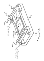
図1はカラーフィルタ製造装置の一実施形態を示す斜視図である。 FIG. 1 is a perspective view showing an embodiment of a color filter manufacturing apparatus.
このカラーフィルタ製造装置は、機台1上に保持ステージの一実施形態である吸着テーブル3、塗布ガントリー4、カメラガントリー6などを支承している。
In this color filter manufacturing apparatus , a suction table 3, a
吸着テーブル3は、ガラス基板2を吸着保持するものであり、このガラス基板2の位置決めを達成するために、図示しない駆動機構、ガイド機構によって、回転駆動されるとともに、Y方向に駆動される。
The suction table 3 holds the
塗布ガントリー4は、インクジェットヘッドバー5を保持するものであり、ガラス基板2にカラー材料を塗布するために、図示しない駆動機構、ガイド機構によって、X方向に駆動される。また、ガラス基板2に対する相対位置を調整するために、図示しない駆動機構、ガイド機構によって、Z方向、Y方向に駆動される。
The
カメラガントリー6は、ガラス基板2のアラインメントのためのアラインメントカメラ7、8、およびガラス基板2に供給されたカラー材料を検出するためのスキャンカメラ9を保持するものであり、アラインメント、カラー材料検出のために、図示しない駆動機構、ガイド機構によって、X方向に駆動される。また、図示しない駆動機構、ガイド機構によって、アラインメントカメラ7、8、スキャンカメラ9をY方向に駆動する。
The
アラインメントカメラ7、8はガラス基板2のマーク(図示せず)を検出するものであり、アラインメントカメラ7、8によるマーク検出結果に基づいて吸着テーブル3を回転させ、および/またはY方向に移動させることにより、ガラス基板2のアラインメントを達成することができる。X方向のアライメント誤差は吐出タイミングを調整することで達成することができる。
The
ただし、スキャンカメラ9に代えて二次元CCDカメラを採用することもできる。
なお、X、Yは、吸着テーブル3により吸着保持されたガラス基板2の上面と平行な平面を規定すべく設定された互いに直交する方向を表し、Zは、X、Yにより規定された平面と直交する方向を表している。
However, a two-dimensional CCD camera can be employed instead of the
X and Y represent directions orthogonal to each other set to define a plane parallel to the upper surface of the
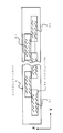
図2はインクジェットヘッドバー5の構成を示す概略図である。
このインクジェットヘッドバー5は、複数個のインクジェットヘッド51を整列させてなるものであり、各インクジェットヘッド51は、複数個のインクジェットノズル52を整列させてなるものである。そして、複数個のインクジェットヘッド51を整列は、全てのインクジェットノズル52のX方向の間隔、Y方向の間隔がそれぞれ所定の間隔となるように設定されている。
FIG. 2 is a schematic view showing the configuration of the
The
ここで、インクジェットノズル52の必要数は、次のように定められる。
なお、以下において、「ピクセル内顔料膜厚」はピクセル内に必要な顔料膜厚[μm]であり、「ピクセル面積」はピクセル1つ当りの面積[μm2]であり、「インク顔料濃度」はインク内の顔料濃度[%]であり、「ノズル平均吐出量」はインクジェットノズルが1回で吐出する量の平均値[pl]であり、「ピクセルに対するノズル吐出回数」はピクセル1つ当りにインクジェットノズル1つが吐出を行う回数[回]であり、「ピクセル1つの必要インク量」はピクセル1つ当りに必要なインクの塗布量であり、「ノズル必要数」はピクセルを塗布するために必要なインクジェットノズルの数[個]である。
ピクセル1つの必要インク量は次の式で算出される。
Here, the required number of inkjet nozzles 52 is determined as follows.
In the following, “in-pixel pigment film thickness” is the pigment film thickness [μm] required in the pixel, “pixel area” is the area per pixel [μm 2 ], and “ink pigment density” Is the pigment concentration [%] in the ink, the “nozzle average discharge amount” is the average value [pl] of the amount that the inkjet nozzle discharges at one time, and the “nozzle discharge count for the pixel” is per pixel. The number of times one inkjet nozzle performs ejection [times], “necessary amount of ink per pixel” is the amount of ink applied per pixel, and “necessary number of nozzles” is necessary for applying pixels The number of ink jet nozzles.
The required ink amount for one pixel is calculated by the following equation.
ピクセル1つの必要インク量=(ピクセル内顔料膜厚×ピクセル面積×100)/(インク顔料濃度×1000)=(ピクセル内顔料膜厚×ピクセル面積)/(インク顔料濃度×10)
ここで、「×100」はインク顔料濃度の単位が%であることに対応しており、「×1000」は[μm3]を[pl]に単位変換するためのものである。
これから、ノズル必要数は次の式で算出される。
Required amount of ink per pixel = (Pigment thickness in pixel × Pixel area × 100) / (Ink pigment density × 1000) = (Pigment thickness in pixel × Pixel area) / (Ink pigment density × 10)
Here, “× 100” corresponds to the unit of the ink pigment concentration being%, and “× 1000” is for converting [μm 3 ] into [pl].
From this, the required number of nozzles is calculated by the following equation.
ノズル必要数=(ピクセル1つの必要インク量)/(ノズル平均吐出量×ピクセルに対するノズル吐出回数)
上の両式から、ノズル必要数は次のように算出される。
Necessary number of nozzles = (required ink amount per pixel) / (average nozzle ejection amount × number of nozzle ejections per pixel)
From the above equations, the required number of nozzles is calculated as follows.
ノズル必要数=(ピクセル内顔料膜厚×ピクセル面積)/(インク顔料濃度×ノズル平均吐出量×ピクセルに対するノズル吐出回数×10)
そして、本実施形態においては、上記のように算出されたノズル必要数よりも10%以上多い数のインクジェットノズルを設けている。
Necessary number of nozzles = (in-pixel pigment film thickness × pixel area) / (ink pigment density × nozzle average ejection amount × number of nozzle ejections per pixel × 10)
In the present embodiment, the number of inkjet nozzles that is 10% or more greater than the required number of nozzles calculated as described above is provided.
さらに説明する。 Further explanation will be given.
インクジェットノズルが1回で吐出する量の平均値を20pl、ピクセルの必要塗布量を200plとすると、ピクセルに対するインクジェットノズルの必要数が10個となるので、ノズル必要数よりも10%以上多い数は11以上となる。そして、インクジェットノズルの数を必要数よりも多くすることにより、インクジェットノズル選択の選択肢を拡げることができる。 If the average value of the amount ejected by an inkjet nozzle at one time is 20 pl and the required application amount of pixels is 200 pl, the required number of inkjet nozzles per pixel is 10. Therefore, the number more than 10% more than the required number of nozzles is 11 or more. And the choice of an inkjet nozzle can be expanded by making the number of inkjet nozzles more than the required number.
ただし、1つのインクジェットノズルから2滴吐出する場合には、上記の条件下でのノズル必要数が5個であるから、インクジェットノズルの数を6個以上(ノズル必要数よりも20%以上多い数)とすることにより、インクジェットノズル選択の選択肢を拡げることができる。 However, when two drops are ejected from one inkjet nozzle, the required number of nozzles under the above conditions is five, so the number of inkjet nozzles is six or more (a number that is 20% more than the required number of nozzles). ), The options for selecting the ink jet nozzle can be expanded.
ピクセルに対してノズル必要数が10個である場合においては、通常のインクジェットノズルの配置が図12に#1〜#10で示すようになり、インクジェットノズルの配置は、dpi表記すると、762以上、846.6667以下となる。インクジェットノズルはピクセルに対して10個のみが対応しており、必要数だけ存在している。 When the required number of nozzles is 10 for a pixel, the arrangement of normal inkjet nozzles is as shown by # 1 to # 10 in FIG. 12, and the arrangement of inkjet nozzles is 762 or more when expressed in dpi. 846.6667 or less. Only 10 inkjet nozzles correspond to pixels, and there are as many as necessary.
例えば、ピクセルに対応しているインクジェットノズル#1〜#10の吐出量が表1に示すようになっている場合(各インクジェットノズルに10%の吐出量ばらつきが存在している場合)には、ピクセルに対しての塗布量が198.3223plとなり、ピクセルの必要塗布量200plに対する誤差は1.677702plとなる。
For example, when the discharge amounts of the

しかし、図13に示すように、ピクセルに対応するインクジェットノズルを11個とした場合(ノズル必要数よりも10%多いインクジェットノズル#1〜#11を配置した場合)には、インクジェットノズルの配置は、dpi表記すると、846.6667以上、931.3333以下となる。そして、ピクセルに対するノズル必要数が10個であるから、使用可能なインクジェットノズルの組み合わせは、表2に示すように、11通りになる。表2において、最も左のノズル番号は、使用されないインクジェットノズルの番号であり、その右の吐出量は、使用されないインクジェットノズルの吐出量であり、その右の合計は使用される全てのインクジェットノズルによる総吐出量であり、最も右の欄は使用される全てのインクジェットノズルの番号の組み合わせである。
However, as shown in FIG. 13, when the number of inkjet nozzles corresponding to the pixels is 11 (when 10% more
表2から分かるように、使用される10個のインクジェットノズルの組み合わせによって総吐出量が変化し、ピクセルの必要塗布量200plに近い総吐出量が実現できる可能性が高くなり、インクジェットノズル#1〜#9、#11の組み合わせを採用すれば、誤差が0.445066plとなり、ピクセルの必要塗布量200plに最も近くなる。
図14は1440dpiでインクジェットノズルが配置されたインクジェットヘッドの一例を示す概略図である。
As can be seen from Table 2, the total discharge amount varies depending on the combination of the 10 inkjet nozzles used, and it is highly possible that a total discharge amount close to the required application amount of 200 pl of pixels can be realized. If the combination of # 9 and # 11 is employed, the error is 0.445066 pl, which is closest to the required application amount of 200 pl for the pixel.
FIG. 14 is a schematic view showing an example of an inkjet head in which inkjet nozzles are arranged at 1440 dpi.
1440dpiで配置されたインクジェットノズルのY方向の間隔は、
25.4[mm]/1440[dpi]=0.017639[mm]=17.63889[μm]となり、Y方向の長さが300[μm]のピクセルに対して16個のインクジェットノズル#1〜#16が対応することになる。
The interval in the Y direction of the inkjet nozzles arranged at 1440 dpi is
25.4 [mm] / 1440 [dpi] = 0.017639 [mm] = 17.663889 [μm], and 16
したがって、ノズル必要数よりも60%多い数のインクジェットノズルが存在することになる。そして、16個のインクジェットノズルから10個のインクジェットノズルを選択する組み合わせは、16C10=8008通り存在することになる。 Therefore, there are 60% more inkjet nozzles than the required number of nozzles. Then, there are 16 C 10 = 8008 combinations for selecting 10 inkjet nozzles from 16 inkjet nozzles.
したがって、10個のインクジェットノズルの最適な組み合わせを選択することによって、ピクセルの必要塗布量200plに非常に近い塗布量を実現することができる。 Therefore, by selecting an optimal combination of 10 inkjet nozzles, it is possible to realize an application amount very close to the required application amount 200 pl of pixels.
なお、インクジェットノズル52は、所定個数を単位として斜め方向に配列されているので、塗布ガントリー4をX方向に駆動しながら、インクジェットノズル52を順次動作させることによって、Y方向に直線的に整列させた状態でカラー材料を塗布することができる。
Since the inkjet nozzles 52 are arranged in an oblique direction with a predetermined number as a unit, the inkjet nozzles 52 are sequentially operated while driving the
図2に示すインクジェットヘッドバー5は、赤(R)、緑(G)、青(B)のカラー材料のいずれかを塗布するためのものであり、特には図示していないが、他のカラー材料を塗布するためのインクジェットヘッドバーも設けられている。
The ink-
図3はインクジェットノズル52を選択するためにインクジェットヘッドバー5を制御するための構成を示す概略ブロック図である。
FIG. 3 is a schematic block diagram showing a configuration for controlling the
図3に示す構成は、スキャンカメラ9による撮像データ(例えば、全てのインクジェットノズル52を動作させた状態に対応する撮像データ)を入力としてカラー材料の面積、直径、または体積を算出する画像処理装置11、算出された面積、直径、または体積を保持するメモリ(吐出データテーブル)12、メモリ12に保持されている面積、直径、または体積を考慮して動作させるべきインクジェットノズル52を選択するためにインクジェットヘッドバー5を制御する制御装置13を有している。
The configuration shown in FIG. 3 is an image processing device that calculates the area, diameter, or volume of a color material using image data captured by the scan camera 9 (for example, image data corresponding to a state in which all inkjet nozzles 52 are operated) as an input. 11. To select a memory (discharge data table) 12 that holds the calculated area, diameter, or volume, and to select an inkjet nozzle 52 that should be operated in consideration of the area, diameter, or volume held in the memory 12 A control device 13 for controlling the
したがって、インクジェットヘッドバー5による塗布動作を行う毎にメモリ12に保持されている面積、直径、または体積を更新することができ、インクジェットヘッドバー5による次の塗布動作を行うに当って、最新の面積、直径、または体積を考慮して動作させるべきインクジェットノズル52を選択するためにインクジェットヘッドバー5を制御することができる。
Accordingly, the area, diameter, or volume held in the
なお、制御装置13は、カラー材料の供給量を一定量にすべくインクジェットノズル52を選択するようインクジェットヘッドバー5を制御するものであってもよく、カラー材料の供給量を許容誤差範囲内にすべくインクジェットノズル52を選択するようインクジェットヘッドバー5を制御するものであってもよい。
The control device 13 may control the
前者の場合には、カラー材料の塗布品質を著しく高めることができる。逆に、後者の場合には、カラー材料の塗布品質の維持と使用可能なインクジェットノズルの数の増加とを両立させることができる。 In the former case, the coating quality of the color material can be remarkably improved. On the contrary, in the latter case, it is possible to achieve both the maintenance of the coating quality of the color material and the increase in the number of usable inkjet nozzles.
次いで、上記の構成のカラーフィルタ製造装置の作用を説明する。 Next, the operation of the color filter manufacturing apparatus having the above configuration will be described.
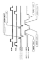
図4はカラー材料塗布処理およびテストパターン検査処理を説明するタイミングチャート、図8は吐出データテーブル作成処理を説明するフローチャート、図9はカラーフィルタ製造処理を説明するフローチャートである。
先ず、図9を参照してカラーフィルタ製造処理を説明する。
FIG. 4 is a timing chart for explaining the color material application process and the test pattern inspection process, FIG. 8 is a flowchart for explaining the ejection data table creation process, and FIG. 9 is a flowchart for explaining the color filter manufacturing process.
First, the color filter manufacturing process will be described with reference to FIG.
ステップSP1において、図示しない搬入ロボットなどによる吸着テーブル3へのガラス基板2の搬入が行われた後に、ステップSP2において、カメラガントリー6を往動させてガラス基板2のマークを検出し、検出結果に応じて搬入ロボットなどを動作させることによって、ガラス基板2の位置決めを達成する。そして、ステップSP3において、吸着テーブル3によりガラス基板2を吸着し、その後、ステップSP4において、カメラガントリー6を往動させ、ステップSP5において、ガラス基板2のアラインメントを行い、ステップSP6において、カメラガントリー6を復動させる。
In step SP1, after the
次いで、ステップSP7において、往路塗布か復路塗布かを判定し、往路塗布であると判定された場合には、ステップSP8において、塗布ガントリー4を往動させるとともに、X座標値を出力し、逆に、ステップSP7において復路塗布であると判定された場合には、ステップSP9において、塗布ガントリー4を復動させる。そして、ステップSP8またはステップSP9の処理が行われた後は、ステップSP10において、X座標値に基づいて塗布が終端まで行われたか否かを判定する。ここで、必要なインクジェットノズル52の選択は、カラー材料の供給量を一定量にすべくインクジェットノズル52を選択するよう行ってもよく、カラー材料の供給量を許容誤差範囲内にすべくインクジェットノズル52を選択するよう行ってもよい。前者の場合には、塗布品質を著しく高めることができる。逆に、後者の場合には、塗布品質の維持と使用可能なインクジェットノズル52の数の増加とを両立させることができる。
Next, in step SP7, it is determined whether the application is forward or inward. If it is determined that the application is forward, the
なお、X座標値を検出する場合には、塗布ガントリー4とガラス基板2との相対移動を停止しておく。したがって、インクジェットノズル52穴直下の着弾痕はノズル孔配列を転写し、吐出時の曲がりなどの影響で微妙なずれが発生するが、実際の着弾痕に基づく検出が行われるので、問題は生じない。
When detecting the X coordinate value, the relative movement between the
図11はインクジェットノズル52からの着弾痕の一例を示す図である。 FIG. 11 is a diagram illustrating an example of a landing mark from the inkjet nozzle 52.
図11には、ノズル列、ノズル番号により定まる着弾痕を示しており、Pは画素ピッチ、L1〜L5はノズル列塗布方向間隔である。 FIG. 11 shows landing marks determined by nozzle rows and nozzle numbers, P is a pixel pitch, and L1 to L5 are intervals in the nozzle row application direction.
図10は吐出データテーブルの一例を示す図であり、塗布走査回数、塗布方向画素番号、塗布方向画素位置、ノズル列、塗布ガントリーX座標値、全ノズルの吐出パターンが設定されている。なお、X0は初期移動量、Pgは画素ピッチ、L1〜Lnはノズル列塗布方向間隔、mは2以上の自然数である。 FIG. 10 is a diagram showing an example of a discharge data table, in which the number of application scans, application direction pixel numbers, application direction pixel positions, nozzle rows, application gantry X coordinate values, and the discharge patterns of all nozzles are set. X0 is an initial movement amount, Pg is a pixel pitch, L1 to Ln are intervals in the nozzle row application direction, and m is a natural number of 2 or more.
そして、ステップSP10において塗布が終端までは行われていないと判定された場合には、ステップSP11において、塗布ガントリー4のX座標値出力信号と吐出データテーブルとを比較し、ステップSP12において、X座標値と吐出データとが一致したか否かを判定し、X座標値と吐出データとが一致したと判定された場合には、ステップSP13において、インクジェットノズル52による吐出動作を行う。
If it is determined in step SP10 that the application has not been performed to the end, in step SP11 , the X coordinate value output signal of the
そして、ステップSP13の処理が行われた場合、またはステップSP12においてX座標値と吐出データとが一致しなかったと判定された場合には、再びステップSP10の判定を行う。 Then, when the process of step SP13 is performed, or when it is determined in step SP12 that the X coordinate value and the discharge data do not match, the determination of step SP10 is performed again.
また、ステップSP10において塗布が終端まで行われたと判定された場合には、ステップSP14において、往路1回目の塗布であるか否かを判定する。 If it is determined in step SP10 that the application has been performed up to the end, it is determined in step SP14 whether or not the application is the first outbound.
そして、往路1回目の塗布であると判定された場合には、ステップSP15において、塗布ガントリー4をテストパターン塗布位置に移動させ、ステップSP16において、テストパターンを形成する(具体的には、例えば、X方向移動、およびインクジェットノズル52の選択で千鳥状のテストパターンを形成する)。
そして、ステップSP14において往路1回目の塗布ではないと判定された場合には、またはステップSP16の処理が行われた場合には、ステップSP17において、所定の回数の塗布が行われたか否かを判定し、所定の回数の塗布が行われていないと判定された場合には、ステップSP18において、塗布ガントリー4を停止させ、インクジェットヘッドバー5をY方向に移動させ、再びステップSP7の判定を行う。なお、Y方向の移動距離は、着弾痕とほぼ等しい距離であればよい。
逆に、ステップSP17において所定の回数の塗布が行われたと判定された場合には、ステップSP19において、塗布を終了し、ステップSP20において、ガラス基板2の吸着を解除して排出処理を行い、そのまま一連の処理を終了する。
If it is determined that the first coating is applied, the
If it is determined in step SP14 that it is not the first application in the outward path, or if the process in step SP16 is performed, it is determined in step SP17 whether or not a predetermined number of applications have been performed. If it is determined that the predetermined number of times of application has not been performed, in step SP18, the
On the contrary, if it is determined in step SP17 that the predetermined number of times of application has been performed, the application is terminated in step SP19, and in step SP20, the suction of the
以上を要約すれば、
吸着テーブル3へのガラス基板2の搬入が行われた後に、カメラガントリー6を往動させてガラス基板2のマークを検出し、検出結果に応じて吸着テーブル3を動作させることによって、ガラス基板2のアラインメントを達成する。その後、カメラガントリー6を復動させる。
In summary,
After the
次いで、塗布ガントリー4を往動させ、かつ吐出データテーブルを参照して必要なインクジェットノズル52を選択するようインクジェットヘッドバー5を制御して1回目の往路塗布を行う。
Next, the
その後、塗布ガントリー4をY方向に僅かに移動させた状態で復動させ、かつ吐出データテーブルを参照して必要なインクジェットノズル52を選択するようインクジェットヘッドバー5を制御することによって1回目の復路塗布を行い、この間に、カメラガントリー6を往動させてスキャンカメラ9によりガラス基板2のテストパターンの検査を行い、その後、カメラガントリー6を復動させる。また、検査結果を用いて吐出データテーブルを更新する。
Thereafter, the
その後、塗布ガントリー4をY方向に僅かに移動させた状態で往動させ、かつ吐出データテーブルを参照して必要なインクジェットノズル52を選択するようインクジェットヘッドバー5を制御することによって、2回目の往路塗布を行う。
Thereafter, the
その後、塗布ガントリー4をY方向に僅かに移動させた状態で復動させ、かつ吐出データテーブルを参照して必要なインクジェットノズル52を選択するようインクジェットヘッドバー5を制御することによって2回目の復路塗布を行う。
Thereafter, the
その後、ガラス基板2の吸着保持を停止し、吸着テーブル3から搬出する。
Thereafter, the suction holding of the
その後、上記の一連の処理を反復的に行うことによって、所望枚数のカラーフィルタを製造することができる。 Thereafter, a desired number of color filters can be manufactured by repeatedly performing the series of processes described above.
すなわち、一度のカラー材料の塗布を行った場合には、インクジェットノズル52同士の間隔と等しい間隔でカラー材料が付着するので、カラー材料を連続的に塗布した状態にはならない。 That is, when the color material is applied once, the color material adheres at an interval equal to the interval between the ink jet nozzles 52, so that the color material is not continuously applied.
しかし、上記のタイミングチャートに従う処理を行った場合には、Y方向の位置を僅かに変化させて塗布を行うのであるから、最終的に、図4、図5に示すように、ガラス基板2上に形成されたブラックマトリックス22の該当する画素領域23内にカラー材料を連続的に塗布することができる。
次いで、図8を参照して吐出データテーブル作成処理を説明する。
ステップSP1において、テスト用基板を吸着テーブル3に搬入し、ステップSP2において、テスト用基板の位置決めを行い、ステップSP3において、テスト用基板を吸着テーブル3に吸着保持し、ステップSP4において、カメラガントリー6を往動させ、ステップSP5において、テスト用基板のアラインメントを行い、ステップSP6において、カメラガントリー6を復動させる。
そして、ステップSP7において、塗布ガントリー4を往動させるとともに、X座標値を出力し、ステップSP8において、テストパターン塗布位置に到達したか否かを判定し、テストパターン塗布位置に到達していないと判定された場合には、再びステップSP7の処理を行う。
ステップSP8においてテストパターン塗布位置に到達したと判定された場合には、ステップSP9において、塗布ガントリー4を停止させ、インクジェット全孔(塗布ガントリー4の全てのインクジェットノズル52)からカラー材料を1滴吐出し、ステップSP10において、塗布ガントリー4を復動させ、待機位置で停止させる。
そして、ステップSP11において、カメラガントリー6を往動させ、ステップSP12において、テストパターン検査位置に到達したか否かを判定し、テストパターン検査位置に到達していないと判定された場合には、再びステップSP11の処理を行う。
ステップSP12においてテストパターン検査位置に到達したと判定された場合には、ステップSP13において、カメラガントリー6を停止させ、ステップSP14において、スキャンカメラ9をY方向に移動させてテストパターンを検出し、テストパターンを検出した後にスキャンカメラ9をY方向に復動させる。
ステップSP14の処理後、ステップSP15において、カメラガントリー6を復動させて待機位置で停止させ、ステップSP16において、テスト用基板の吸着を解除して、排出し、一連の処理を終了する。
また、ステップSP15、ステップSP16の処理と並行して、ステップSP17において、スキャンカメラ9による検出信号を画像処理し、X,Y座標を演算し、ステップSP18において、テストパターンのカラー材料着弾痕から検出した座標位置情報と、カラー材料着弾痕の面積、直径または体積を入力し、ステップSP19において、テスト用基板上の全画素の位置情報を入力し、ステップSP20において、その他のパラメータを入力し、ステップSP21において、データテーブルの演算/作成を行い、ステップSP22において、位置情報(座標値)と、カラー材料着弾痕の面積、直径または体積と、演算結果を吐出データテーブルに記憶し、一連の処理を終了する。
However, when the processing according to the above timing chart is performed, since the coating is performed by slightly changing the position in the Y direction, finally, on the
Next, the ejection data table creation process will be described with reference to FIG.
In step SP1, the test substrate is carried into the suction table 3. In step SP2, the test substrate is positioned. In step SP3, the test substrate is sucked and held on the suction table 3. In step SP4, the
In step SP7, the
If it is determined in step SP8 that the test pattern application position has been reached, in step SP9, the
In step SP11, the
If it is determined in step SP12 that the test pattern inspection position has been reached, the
After the process of step SP14, the
In parallel with the processing of step SP15 and step SP16, in step SP17, the detection signal from the
そして、メモリ(吐出データテーブル)12を参照して、2回の往路塗布、および2回の復路塗布によるカラー材料の供給量を一定量にすべくインクジェットノズル52を選択するようインクジェットヘッドバー5を制御することにより、カラー材料の塗布品質を高めることができる。また、メモリ(吐出データテーブル)12を参照して2回の往路塗布、および2回の復路塗布によるカラー材料の供給量を許容誤差範囲内にすべくインクジェットノズル52を選択するようインクジェットヘッドバー5を制御することにより、カラー材料の塗布品質と選択可能なインクジェットノズル52の数を両立させることができる。
Then, referring to the memory (ejection data table) 12, the ink
また、吐出データテーブルを参照して必要なインクジェットノズル52を選択するのであるから、カラー材料の塗布品質を高めることができる。
図6はガラス基板2上に6個のカラーフィルタCFが形成された状態を示しており、しかも、カラーフィルタCFよりも外方の余剰領域に各カラー材料毎のテストパターンTPが形成されている。
Further, since the necessary inkjet nozzles 52 are selected with reference to the ejection data table, the coating quality of the color material can be improved.
FIG. 6 shows a state in which six color filters CF are formed on the
図7はテストパターンTP形成部を拡大して示す図であり、カメラガントリー6により検査されるものとして、1回目の往路塗布および1回目の復路塗布によってのみ形成されたテストパターンTPを示している。
FIG. 7 is an enlarged view of the test pattern TP forming portion, and shows the test pattern TP formed only by the first forward coating and the first backward coating as being inspected by the
したがって、カラー材料同士は互いに離れているとともに千鳥状となっている。
そして、カメラガントリー6のスキャンカメラ9によりテストパターンTPを検査することができ、塗布毎にインクジェットノズルの吐出量不均一(ばらつき)を確認でき、直ちに必要な対処(吐出量確認を行った時点での最適塗布量になるインクジェットノズル52の組み合わせを選択することなど)を行うことができ、不良品が製造されることを最小限にすることができる。
Therefore, the color materials are separated from each other and are staggered.
Then, the test pattern TP can be inspected by the
また、千鳥状にすることによって、カラー材料同士の間隔を大きくすることができ、画像処理にゆとりを持たせることができるので、検査精度を高めることができる。 Further, by forming a staggered pattern, the interval between the color materials can be increased, and the image processing can be given a certain amount of space, so that the inspection accuracy can be increased.
また、カメラガントリー6のスキャンカメラ9によるテストパターンTPの検査は、塗布ガントリー4を動作させることによる塗布動作中に行われるので、テストパターンTPを検査するための時間を余分に必要とすることがなく、タクトタイムが長くなってしまうという不都合を未然に防止することができる。
Further, since the test pattern TP is inspected by the
また、カメラガントリー6のスキャンカメラ9によるテストパターンTPの検査は、ガラス基板2に形成されたテストパターンTPに基づいて行われるので、カラー材料の塗布がどのように行われるかを精度よく検査することができる。
以上には、塗布ガントリー4を吸着テーブル2に対してX方向に移動させるようにした実施形態を説明したが、塗布ガントリー4を固定し、吸着テーブル3を移動させるように構成することが可能である。
In addition, since the test pattern TP is inspected by the
The embodiment in which the
以上の実施形態においては、インクジェットノズルを選択することによってピクセルに対する総塗布量を必要塗布量に近づけるようにしているだけであって、インクジェットノズル52から吐出される吐出1回当たりの量を変化させることは全く行っていない。
しかし、インクジェットヘッド51を複数持つインクジェットヘッドバー5を塗布ガントリー4に設け、前記インクジェットヘッド51内のインクジェットノズル52から吐出される吐出1回当たりの量を変化させるノズル制御部(図示せず)と、前記インクジェットヘッド51内の各インクジェットノズル52から吐出される吐出1回当たりの量の合計をインクジェットヘッド51毎に所定量に近づけるようにノズル制御部を制御する上位制御部(図示せず)とをさらに備えていることが好ましい。
In the above embodiment, the ink jet nozzle is selected so that the total application amount for pixels is made close to the required application amount, and the amount per discharge discharged from the ink jet nozzle 52 is changed. It doesn't go at all.
However, an
前記ノズル制御部は、例えば、インクジェットノズル52に印加する駆動電圧を変化させることによって吐出1回当たりの吐出量を変化させるものである。 For example, the nozzle control unit changes the discharge amount per discharge by changing the drive voltage applied to the inkjet nozzle 52.
前記上位制御部は、例えば、スキャンカメラ9によって得られた吐出量不均一性データ等を入力として、インクジェットヘッド51内の各インクジェットノズル52の吐出1回当たりの吐出量の合計(インクジェットヘッド51の吐出1回当たりの吐出量)を目標とする吐出量に近づけるように、各ノズル制御部に対する動作指令を供給するものである。
この場合には、塗布量をインクジェットヘッド51毎に合わせ込むことができる。さらに説明すると、特定のインクジェットヘッド51がインクの粘度などの影響を受けて吐出量が低くなった場合にも、上位制御部によって各ノズル制御部に対する動作指令を設定し、ノズル制御部によってインクジェットノズル52に印加する駆動電圧等を変えることで、他のインクジェットヘッド51との吐出量ばらつきを抑えることができる。
The upper control unit receives, for example, discharge amount non-uniformity data obtained by the
In this case, the coating amount can be adjusted for each inkjet head 51. More specifically, even when a specific inkjet head 51 is affected by the viscosity of the ink and the discharge amount becomes low, an operation command for each nozzle control unit is set by the upper control unit, and the nozzle control unit sets the inkjet nozzle. By changing the drive voltage applied to the nozzle 52, it is possible to suppress variations in the discharge amount with the other inkjet heads 51.
インクジェットヘッド内のインクジェットノズルは当然ばらつきを持っているが、このようなばらつきに対しては、前記の実施形態によって対処することができる。 The inkjet nozzles in the inkjet head naturally have variations, but such variations can be dealt with by the above-described embodiment.
2 ガラス基板
3 吸着テーブル
5 インクジェットヘッドバー
9 スキャンカメラ
11 画像処理装置
12 メモリ
13 制御装置
51 インクジェットヘッド
52 インクジェットノズル
2
Claims (7)
前記塗布対象物(2)に塗布材を供給する複数のインクジェットノズル(52)を有するインクジェットヘッド(51)と、
前記塗布対象物(2)に各インクジェットノズル(52)から1回の動作で供給された塗布材の量を計測する計測手段(9)(11)と、
各インクジェットノズル毎の計測された量を保持する保持手段(12)と、
保持手段(12)の保持データを参照して、前記塗布対象物(2)に塗布材を供給するためのインクジェットノズル(52)を選択するよう前記インクジェットヘッド(51)を制御する制御手段(13)と、
前記インクジェットヘッド(51)を複数持つインクジェットヘッド群と、前記インクジェットヘッド(51)内のインクジェットノズル(52)から吐出される吐出1回当たりの量を変化させるノズル制御手段と、
前記インクジェットヘッド(51)内の各インクジェットノズル(52)から吐出される吐出1回当たりの量の合計をインクジェットヘッド(51)毎に所定量に近づけるようにノズル制御手段を制御する上位制御手段とを備えることを特徴とする塗布装置。 A holding stage (3) for holding a coating object (2);
An inkjet head (51) having a plurality of inkjet nozzles (52) for supplying a coating material to the application object (2);
Measuring means (9) (11) for measuring the amount of the coating material supplied to the coating object (2) from each inkjet nozzle (52) in one operation;
Holding means (12) for holding the measured amount of each inkjet nozzle;
Control means (13) for controlling the ink-jet head (51) so as to select an ink-jet nozzle (52) for supplying the coating material (2) with reference to the data held by the holding means (12). a),
A group of inkjet heads having a plurality of inkjet heads (51); and a nozzle control means for changing the amount per ejection discharged from the inkjet nozzles (52) in the inkjet head (51);
Upper control means for controlling the nozzle control means so that the total amount per discharge discharged from each ink jet nozzle (52) in the ink jet head (51) approaches a predetermined amount for each ink jet head (51); A coating apparatus comprising:
Priority Applications (1)
| Application Number | Priority Date | Filing Date | Title |
|---|---|---|---|
| JP2007020534A JP5073301B2 (en) | 2007-01-31 | 2007-01-31 | Coating device |
Applications Claiming Priority (1)
| Application Number | Priority Date | Filing Date | Title |
|---|---|---|---|
| JP2007020534A JP5073301B2 (en) | 2007-01-31 | 2007-01-31 | Coating device |
Publications (2)
| Publication Number | Publication Date |
|---|---|
| JP2008183528A JP2008183528A (en) | 2008-08-14 |
| JP5073301B2 true JP5073301B2 (en) | 2012-11-14 |
Family
ID=39726907
Family Applications (1)
| Application Number | Title | Priority Date | Filing Date |
|---|---|---|---|
| JP2007020534A Active JP5073301B2 (en) | 2007-01-31 | 2007-01-31 | Coating device |
Country Status (1)
| Country | Link |
|---|---|
| JP (1) | JP5073301B2 (en) |
Families Citing this family (3)
| Publication number | Priority date | Publication date | Assignee | Title |
|---|---|---|---|---|
| JP2016116993A (en) * | 2016-03-31 | 2016-06-30 | 株式会社三洋物産 | Game machine |
| JP2019076849A (en) * | 2017-10-25 | 2019-05-23 | 東レエンジニアリング株式会社 | Coating method and coating device |
| JP2018034059A (en) * | 2017-12-12 | 2018-03-08 | 株式会社三洋物産 | Game machine |
Family Cites Families (6)
| Publication number | Priority date | Publication date | Assignee | Title |
|---|---|---|---|---|
| JP2907772B2 (en) * | 1995-05-30 | 1999-06-21 | キヤノン株式会社 | Method and apparatus for measuring ink ejection amount, printing apparatus, and method for measuring ink ejection amount in printing apparatus |
| JP2967052B2 (en) * | 1995-09-08 | 1999-10-25 | キヤノン株式会社 | Method and apparatus for manufacturing color filter |
| JP2001041799A (en) * | 1999-07-30 | 2001-02-16 | Canon Inc | Volume measuring method and volume measuring device of droplet, and recording medium |
| JP2004338171A (en) * | 2003-05-14 | 2004-12-02 | Seiko Epson Corp | Drawing device, drawing method, device, and electronic device |
| JP2005119139A (en) * | 2003-10-16 | 2005-05-12 | Seiko Epson Corp | Method and device for measuring discharge amount of functional liquid droplet jet head, method of controlling driving of functional liquid droplet jet head, liquid droplet jet device, method of manufacturing electrooptical device, electrooptical device, and electronic device |
| JP4682524B2 (en) * | 2004-03-15 | 2011-05-11 | リコープリンティングシステムズ株式会社 | Inkjet coating device |
-
2007
- 2007-01-31 JP JP2007020534A patent/JP5073301B2/en active Active
Also Published As
| Publication number | Publication date |
|---|---|
| JP2008183528A (en) | 2008-08-14 |
Similar Documents
| Publication | Publication Date | Title |
|---|---|---|
| KR101214286B1 (en) | Method and apparatus for manufacturing color filter | |
| CN101309757B (en) | Ink jetting device and ink jetting method | |
| JP2008544333A (en) | Inkjet printing system and method for flat panel display | |
| JP2008264608A (en) | Liquid droplet coating apparatus and liquid droplet coating method | |
| US20110090290A1 (en) | Method for manufacturing patterned layer on substrate | |
| JPWO2008093701A1 (en) | Coating device | |
| JP5073301B2 (en) | Coating device | |
| JP2004141758A (en) | Method of correcting dot position of droplet discharge device, alignment mask, droplet discharge method, electro-optical device and its production method, and an electronic equipment | |
| JP5497654B2 (en) | Droplet application method and apparatus | |
| JP2009175168A (en) | Application equipment and application method | |
| TW200950889A (en) | Coating machine and coating method | |
| JP5243954B2 (en) | Color filter manufacturing method and apparatus | |
| JP2008221183A (en) | Liquid droplet ejection/coating apparatus and method for preparing coated article | |
| JP4403802B2 (en) | Paste applicator | |
| JPWO2008087970A1 (en) | Color filter manufacturing method and apparatus | |
| JP2010204411A (en) | Liquid drop discharge device, liquid drop discharge method, and method of manufacturing color filter | |
| JP2009109799A (en) | Coating device and coating method | |
| JP5416521B2 (en) | Application method | |
| JP5475957B2 (en) | Coating device | |
| JP2010234170A (en) | Coating apparatus | |
| JP2006247500A (en) | Pattern forming apparatus and pattern forming method | |
| KR20230154614A (en) | Apparatus and method for dispensing treating fluid | |
| JP5073295B2 (en) | Coating device | |
| JP2010194528A (en) | Inkjet head modules and coating apparatus | |
| JP2010197546A (en) | Droplet discharge apparatus, method of discharging droplet and method of manufacturing color filter |
Legal Events
| Date | Code | Title | Description |
|---|---|---|---|
| RD02 | Notification of acceptance of power of attorney |
Free format text: JAPANESE INTERMEDIATE CODE: A7422 Effective date: 20090511 |
|
| A621 | Written request for application examination |
Free format text: JAPANESE INTERMEDIATE CODE: A621 Effective date: 20100113 |
|
| A977 | Report on retrieval |
Free format text: JAPANESE INTERMEDIATE CODE: A971007 Effective date: 20111111 |
|
| A131 | Notification of reasons for refusal |
Free format text: JAPANESE INTERMEDIATE CODE: A131 Effective date: 20111122 |
|
| A521 | Request for written amendment filed |
Free format text: JAPANESE INTERMEDIATE CODE: A523 Effective date: 20120123 |
|
| TRDD | Decision of grant or rejection written | ||
| A01 | Written decision to grant a patent or to grant a registration (utility model) |
Free format text: JAPANESE INTERMEDIATE CODE: A01 Effective date: 20120731 |
|
| A01 | Written decision to grant a patent or to grant a registration (utility model) |
Free format text: JAPANESE INTERMEDIATE CODE: A01 |
|
| A61 | First payment of annual fees (during grant procedure) |
Free format text: JAPANESE INTERMEDIATE CODE: A61 Effective date: 20120822 |
|
| R150 | Certificate of patent or registration of utility model |
Ref document number: 5073301 Country of ref document: JP Free format text: JAPANESE INTERMEDIATE CODE: R150 Free format text: JAPANESE INTERMEDIATE CODE: R150 |
|
| FPAY | Renewal fee payment (event date is renewal date of database) |
Free format text: PAYMENT UNTIL: 20150831 Year of fee payment: 3 |
|
| R250 | Receipt of annual fees |
Free format text: JAPANESE INTERMEDIATE CODE: R250 |
|
| R250 | Receipt of annual fees |
Free format text: JAPANESE INTERMEDIATE CODE: R250 |
|
| R250 | Receipt of annual fees |
Free format text: JAPANESE INTERMEDIATE CODE: R250 |
|
| R250 | Receipt of annual fees |
Free format text: JAPANESE INTERMEDIATE CODE: R250 |
|
| R250 | Receipt of annual fees |
Free format text: JAPANESE INTERMEDIATE CODE: R250 |
|
| R250 | Receipt of annual fees |
Free format text: JAPANESE INTERMEDIATE CODE: R250 |
|
| R250 | Receipt of annual fees |
Free format text: JAPANESE INTERMEDIATE CODE: R250 |
|
| R250 | Receipt of annual fees |
Free format text: JAPANESE INTERMEDIATE CODE: R250 |
|
| S531 | Written request for registration of change of domicile |
Free format text: JAPANESE INTERMEDIATE CODE: R313531 |
|
| R350 | Written notification of registration of transfer |
Free format text: JAPANESE INTERMEDIATE CODE: R350 |