JP5072720B2 - Storage member and image forming apparatus - Google Patents
Storage member and image forming apparatus Download PDFInfo
- Publication number
- JP5072720B2 JP5072720B2 JP2008149536A JP2008149536A JP5072720B2 JP 5072720 B2 JP5072720 B2 JP 5072720B2 JP 2008149536 A JP2008149536 A JP 2008149536A JP 2008149536 A JP2008149536 A JP 2008149536A JP 5072720 B2 JP5072720 B2 JP 5072720B2
- Authority
- JP
- Japan
- Prior art keywords
- unit
- image
- document
- storage
- image forming
- Prior art date
- Legal status (The legal status is an assumption and is not a legal conclusion. Google has not performed a legal analysis and makes no representation as to the accuracy of the status listed.)
- Expired - Fee Related
Links
Images


Description
本発明は、格納部材及び画像形成装置に関し、特に原稿及び画像が形成されたシートの秘匿性を確保するための構成に関する。 The present invention relates to a storage member and an image forming apparatus, and more particularly to a configuration for ensuring confidentiality of a document and a sheet on which an image is formed.
従来、デジタル複写機、プリンタ、ファクシミリ等の画像形成装置においては、原稿の画像を読み取る画像読取部と、画像読取部によって読み取った画像情報に基づいてシートに画像を形成する画像形成部を備えたものがある。 2. Description of the Related Art Conventionally, an image forming apparatus such as a digital copying machine, a printer, or a facsimile includes an image reading unit that reads an image of a document and an image forming unit that forms an image on a sheet based on image information read by the image reading unit. There is something.
このような画像形成装置において、シートに画像を形成する場合は、まず原稿搬送部により原稿を画像読取部に搬送し、画像読取部によって原稿画像を読み取った後、画像情報に基づいて画像形成部によりシートに画像を形成する。そして、このようにシートに画像を形成した後、シートをシート排出部に排出する。 In such an image forming apparatus, when an image is formed on a sheet, the document is first transported to the image reading unit by the document transport unit, the document image is read by the image reading unit, and then the image forming unit is based on the image information. Thus, an image is formed on the sheet. And after forming an image on a sheet | seat in this way, a sheet | seat is discharged | emitted to a sheet | seat discharge part.
ところで、このような従来の画像形成装置の一例である複写機において、利用者が複写操作をする際には、原稿台もしくは原稿搬送部を構成する自動原稿給送装置に複写する原稿を置くことで複写動作(画像形成動作)を開始する。 By the way, in a copying machine which is an example of such a conventional image forming apparatus, when a user performs a copying operation, a document to be copied is placed on an automatic document feeder constituting a document table or a document transport unit. The copying operation (image forming operation) is started.
ところが、このような原稿の複写の際、利用者が複写前や複写済の原稿、複写されたシートである成果物を置き忘れる場合がある。ここで、このように原稿や成果物を置き忘れた場合、特に置き忘れた原稿や成果物が他人には見られたくない機密書類等の場合、情報漏洩が発生するおそれがある。 However, when such a manuscript is copied, the user may misplace the pre-copied or copied manuscript or a product that is a copied sheet. Here, if the manuscript or product is misplaced as described above, information leakage may occur particularly in the case of a confidential document or the like in which the misplaced manuscript or product is not desired to be seen by others.
そこで、このような置き忘れによる情報漏洩を防止するため、即ち原稿や成果物の秘匿性を確保するため、近年の複写機においては、画像が読み取られた後の原稿を保管する原稿保管部を設けた物がある(特許文献1参照)。また、同様に、機密情報等が複写され、複写機から排出される成果物を、第三者から秘匿する秘匿手段を設けた物がある(特許文献2参照)。 Therefore, in order to prevent such information leakage due to misplacement, that is, to ensure the confidentiality of the manuscript and the product, a recent copier is provided with a manuscript storage unit for storing the manuscript after the image is read. (See Patent Document 1). Similarly, there is a product provided with a concealing means for concealing a product obtained by copying confidential information or the like and discharged from the copying machine from a third party (see Patent Document 2).
しかしながら、このように原稿保管部や秘匿手段を備えた従来の複写機(画像形成装置)において、複写動作を行っている際、複写しようとしている原稿が覗き見される場合がある。 However, in the conventional copying machine (image forming apparatus) provided with the document storage unit and the concealing means as described above, there is a case where the document to be copied is peeped during the copying operation.
また、原稿台や自動原稿給送装置に置かれた原稿が持ち去られる場合がある。さらに、成果物が、他者の複写行為による成果物と混載される可能性があり、この場合、成果物を無作為的に所有者以外が持ち去っていく場合がある。このように、従来は、原稿及び成果物の秘匿性を確保するのが困難であることから、原稿及び成果物の秘匿性を確保することのできる格納部材の要求が高まっていた。 In addition, a document placed on a document table or an automatic document feeder may be taken away. Further, there is a possibility that the deliverable is mixed with the deliverable resulting from another person's copying. In this case, the deliverable may be taken away by a person other than the owner at random. Thus, conventionally, since it is difficult to ensure the confidentiality of the manuscript and the product, there has been an increasing demand for a storage member that can ensure the secrecy of the manuscript and the product.
そこで、本発明は、このような現状に鑑みてなされたものであり、原稿及び成果物の秘匿性を確保することのできる格納部材及び画像形成装置を提供することを目的とするものである。 Therefore, the present invention has been made in view of such a current situation, and an object thereof is to provide a storage member and an image forming apparatus that can ensure confidentiality of a document and a product.
本発明は、原稿の画像を読み取る画像読取部と、前記画像読取部に原稿を搬送する原稿搬送部と、前記画像読取部によって読み取った画像情報に基づいてシートに画像を形成する画像形成部と、を備えた画像形成装置において、原稿及び前記画像読取部により画像が読み取られた後の画像読取済み原稿を格納する原稿格納部と、前記画像形成部によって画像が形成されたシートを格納するシート格納部とを有する格納部材を着脱自在に備え、前記格納部材の前記原稿格納部に格納された原稿を前記原稿搬送部が前記画像読取部に搬送すると共に画像読取済み原稿を前記原稿格納部に格納し、前記画像形成部によって画像が形成されたシートを装着位置が変更された前記格納部材の前記シート格納部に格納することを特徴とするものである。 The present invention includes an image reading unit that reads an image of a document, a document transport unit that transports the document to the image reading unit, and an image forming unit that forms an image on a sheet based on image information read by the image reading unit. In the image forming apparatus, a document storage unit that stores a document and an image-read original after the image is read by the image reading unit, and a sheet that stores a sheet on which an image is formed by the image forming unit. A storage member having a storage unit is detachably attached. The document stored in the document storage unit of the storage member is transported by the document transport unit to the image reading unit, and the image-read document is stored in the document storage unit. The sheet is stored and the sheet on which the image is formed by the image forming unit is stored in the sheet storing unit of the storing member whose mounting position is changed .
本発明のように、原稿、画像読取済み原稿及び画像が形成されたシートである成果物を同一の格納部材に格納することにより、原稿及び成果物の秘匿性を確保することができる。 As in the present invention, the confidentiality of the original and the product can be ensured by storing the original, the image-read original, and the product, which is the sheet on which the image is formed, in the same storage member.
以下、本発明を実施するための最良の形態を、図面に基づき詳細に説明する。 Hereinafter, the best mode for carrying out the present invention will be described in detail with reference to the drawings.
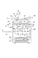
図1は、本発明の第1の実施の形態に係る画像形成装置の一例である複写機の構成を示す図である。 FIG. 1 is a diagram showing a configuration of a copier that is an example of an image forming apparatus according to a first embodiment of the present invention.
図1において、200は複写機、200Aは複写機本体であり、この複写機本体200Aの上面には画像読取装置201が、また複写機本体200Aの内部には画像形成部220が設けられている。また、250は、画像形成装置本体である複写機本体200の複写動作等を制御する制御部である。
In FIG. 1,
画像読取装置201は原稿の画像を読み取る原稿読取部であるスキャナ部202と、スキャナ部202の上面に上下方向に開閉回動可能に設けられ、スキャナ部202に原稿を搬送する原稿搬送部である自動原稿給送装置(ADF)300とを備えている。
The
ここで、スキャナ部202は、スキャナ部202の上面に設けられているシート載置台としてのプラテンガラス203と、プラテンガラス203上の原稿の画像を走査して読み取るための画像読取手段204を備えている。
Here, the
自動原稿給送装置300は、プラテンガラス203に載置された原稿を上方より押えるシート押圧部を構成するものであり、スキャナ部202のシート搬送方向と平行な一端に開閉自在に取付けられている。そして、プラテンガラス203上に原稿を載置する場合は、自動原稿給送装置300を開放した後、プラテンガラス203上の所定の画像読み取り位置に原稿を載置するようにしている。
The
また、この自動原稿給送装置300は、原稿が載置される原稿トレイ301と、原稿を給送する給送部302を備えている。ここで、給送部302は、原稿トレイ301に画像形成面を上にした状態で積載された原稿を順次最上位のものから一枚ずつ取出しプラテンガラス203の一端側(図中左端側)に供給するためのものである。
The
そして、この給送部302には、原稿トレイ301に載置された原稿を給送するための原稿給送手段304と、プラテンガラス203上に原稿を搬送する原稿搬送部305を備えている。なお、この原稿搬送部305には、プラテンガラス203の上面を覆うように搬送ベルト306が設けられている。
The
また、給送部302には画像が読み取られた後の原稿を、原稿トレイ301に排出するための排紙ローラ307が設けられている。そして、この排紙ローラ307は、搬送ベルト306によってプラテンガラス203の左端側から搬出された原稿を受け取って原稿トレイ301に排出する。
The
次に、このように構成された画像読取装置201の、例えば自動原稿給送装置300によりプラテンガラス上に搬送された原稿の画像を読み取る動作について説明する。
Next, an operation of the
この場合、まず自動原稿給送装置300において、原稿トレイ301に載置された原稿を給送部302によりスキャナ部202のプラテンガラス203上に搬送し、この後、原稿は搬送ベルト306により搬送される。次に、原稿は、搬送ベルト306によりプラテンガラス203上の所定の画像読み取り位置に搬送され、この位置で停止する。
In this case, in the
このように原稿が画像読み取り位置で停止した後、スキャナ部202の画像読取手段204を矢印方向に移動し、原稿画像を読み取る。なお、このように画像読取手段204によって読み取られた画像情報は、後述する図5に示す内部メモリ252に画像情報として格納される。
After the original stops at the image reading position in this way, the image reading means 204 of the
次に、このようにしてスキャナ部202において画像が読み取られた後、例えば画像が読み取られた原稿を原稿トレイ301上に排出する場合は、搬送ベルト306を反転させ、画像読取り済の原稿を排紙ローラ307に搬送する。そして、この後、画像読取り済の原稿は、排紙ローラ307により原稿トレイ301に排出される。
Next, after the image is read by the
一方、画像形成部220には、露光手段230、円筒状の感光ドラム221、帯電器222、現像器223、クリーニング装置224が設けられている。さらに、画像形成部220の下流側には定着装置225、排紙ローラ226及び排紙トレイ270を備えたシート排出部271等が配設されている。
On the other hand, the
そして、画像形成部220においてシートに画像を形成する際は、まず既述したように画像読取装置201により読み取られ、内部メモリに格納されている画像情報に基づき、露光手段230が不図示のポリゴンミラー等を介して感光ドラム221に光を照射する。
When the
このとき、感光ドラム221の表面は帯電器222により一様に帯電されており、このように光が照射されると、感光ドラム表面に静電潜像が形成され、この静電潜像を現像器223により現像することにより、感光ドラム表面にトナー像が形成される。
At this time, the surface of the
一方、このようなトナー像形成動作に並行してカセット240にセットされたシートSが給紙ローラ241によってレジストローラ242まで搬送される。次に、シートSは、レジストローラ242によってシート先端と感光ドラム221のトナー像の先端を合わせるようなタイミングで感光ドラム221と転写帯電器243とにより構成される転写部まで搬送される。そして、転写部を通過する際、転写帯電器243に転写バイアスが印加されることにより、感光ドラム上のトナー像がシートSに転写される。
On the other hand, in parallel with such a toner image forming operation, the sheet S set in the
次に、トナー像が転写されたシートSは、定着装置225まで搬送され、定着装置225を通過する際に、トナー像が熱定着される。そして、定着されたシートSは、シート排出部309に設けられた排紙ローラ226により排紙トレイ270に排出される。
Next, the sheet S to which the toner image has been transferred is conveyed to the
ところで、本実施の形態においては、他人には見られたくない機密書類等の秘匿性を確保すべき原稿を複写する場合がある。この場合には、図2に示す格納部材である格納容器102に機密書類等の原稿を格納した後、この格納容器102を図3に示すように自動原稿給送装置300にセットする。
By the way, in the present embodiment, there is a case where a manuscript that should ensure confidentiality such as a confidential document that is not desired to be seen by others may be copied. In this case, after storing a document such as a confidential document in the
ここで、この格納容器102は、格納されている内容物が視認不可となるよう、例えばABS樹脂やポリカーボネート等の不透明な材料により形成されている。なお、半透明の材質であっても、格納された原稿や成果物が視認出来なければ、格納容器102を他の材質のもので形成しても良い。
Here, the
格納容器102は、原稿Dを格納する第1の格納部である原稿格納庫110と、画像原稿が読み取られた読み取り済の原稿(以下、読取原稿という)D1を格納する第2の格納部である読取原稿格納庫104とを備えた原稿格納部を備えている。また、この格納容器102は、後述するように機密書類等の原稿を複写したシートである成果物S1を格納するシート格納部である成果物格納庫122を備えている。
The
なお、図2において、103は格納容器本体102aに一端が軸支され、格納容器本体102aに開閉自在に設けられた第1の蓋であり、原稿Dを格納する際には、この第1の蓋103を開放して原稿格納庫110に格納する。また、105は格納容器本体102aに一端が軸支され、格納容器本体102aに開閉自在に設けられた第1シャッタであり、読取原稿格納庫104に格納された読取原稿D1を取り出す際には、この第1シャッタ105を開放する。
In FIG. 2,
120は格納容器本体102aに一端が軸支され、格納容器本体102aに開閉自在に設けられた第2の蓋であり、成果物格納庫122に格納された成果物S1を取り出す際には、この第2の蓋120を開放して取り出す。
A
107は格納容器本体102aに一端が軸支され、格納容器本体102aに開閉自在に設けられた第2シャッタであり、この第2シャッタ107により原稿格納庫110、読取原稿格納庫104及び成果物格納庫122の一側が閉じられるようになっている。ここで、この第2シャッタ107は、格納容器102を持ち運ぶ際には不図示のバネにより閉じられるようになっている。そして、このように第2シャッタ107が閉じられることにより、格納容器102を持ち運ぶ際、格納容器102から原稿等が飛び出すのを防ぐことができる。
A
なお、第2シャッタ107の下端には係合部106が突設されており、この係合部106は、図3に示すように格納容器102が自動原稿給送装置300にセットされた際、自動原稿給送装置300に設けられた不図示の突起部に引っかかるようになっている。そして、このように係合部106が突起部に引っかかることにより、第2シャッタ107は、不図示のバネに抗しながら下方回動する。
An engaging
ここで、このように第2シャッタ107が下方回動することにより、原稿格納庫110、読取原稿格納庫104及び成果物格納庫122の一側が開放され、この結果、原稿Dの送り出し及び読取原稿D1の格納が可能となる。なお、格納容器102を自動原稿給送装置300にセットした際、第2シャッタ107以外の第1シャッタ105、第1の蓋103及び第2の蓋120は、自動原稿給送装置300と干渉して開放できないように構成されている。
Here, when the
一方、後述するように、全ての原稿Dの読み取りが終了し、読取原稿D1が読取原稿格納庫104に格納されると、格納容器102は自動原稿給送装置300から取り外される。そして、格納容器102は、図4に示すように排紙トレイ270に載置された状態でシート排出部271に設けられた成果物積載部309に着脱自在に装着(セット)される。
On the other hand, as described later, when the reading of all the originals D is completed and the read original D1 is stored in the read
ここで、例えば排紙トレイ270にも、不図示の突起部が設置されており、これにより成果物積載部309に格納容器102がセットされる際にも、格納容器102の第2シャッタ107が開放される。この結果、画像が形成された後、排紙ローラ226から排出される成果物S1が成果物格納庫122に格納される。
Here, for example, a projection (not shown) is also provided on the
なお、図5は、複写機200の制御ブロック図であり、図5に示すように制御部250には、後述するように格納容器102が成果物積載部309にセットされたことを検知する装着検知センサ251が接続されている。そして、制御部250は、装着検知センサ251からの検知信号により内部メモリ252に格納した画像情報を読み出し、この画像情報に基づいて画像形成を行うよう画像形成部220を制御する。また、制御部250には、不図示のコピーボタン及び表示部を備えた操作部253、画像読取装置201等が接続されている。
FIG. 5 is a control block diagram of the copying
次に、このような格納容器102を用いて行われる複写機200の複写動作について説明する。
Next, a copying operation of the copying
まず、ユーザは格納容器102の第1の蓋103を開放することにより、原稿Dを原稿格納庫110に格納し、この後、原稿Dが格納された格納容器102を、図3に示すように自動原稿給送装置300に傾斜した状態でセットする。この際、格納容器102の第2シャッタ107の係合部106が、自動原稿給送装置300に設けられている突起部に引っかかり、第2シャッタ107が開放される。この結果、原稿格納庫110、読取原稿格納庫104及び成果物格納庫122の給送部側が開放される。
First, the user opens the
次に、この状態でコピーボタンが押下されると、自動原稿給送装置300の給送部302により原稿格納庫110に格納されている原稿Dがプラテンガラス203上に送り出され、画像読取手段204により原稿画像が読み取られる。なお、このように画像が読み取られた後、読取原稿D1は、搬送ベルト207の反転と、排紙ローラ307により格納容器102内の読取原稿格納庫104に格納される。なお、このように順次読み取られた原稿Dの画像情報は、一旦、内部メモリ252に格納される。
Next, when the copy button is pressed in this state, the document D stored in the
次に、全ての原稿Dの読み取りが終了すると、格納容器102は自動原稿給送装置300から取り外され、図4に示すように、成果物積載部309に着脱自在に装着(セット)される。なお、このように格納容器102がセットされる際、格納容器102の第2シャッタ107の係合部106が、成果物積載部309に設けられている不図示の突起部に引っかかり、第2シャッタ107が開放される。この結果、原稿格納庫110、読取原稿格納庫104及び成果物格納庫122の排紙ローラ側が開放される。
Next, when the reading of all the documents D is completed, the
ここで、複写機本体200には格納容器102の装着を検知する検知部である装着検知センサ251(図5参照)が設けられている。そして、制御部250は、装着検知センサ251から格納容器102が成果物積載部309にセットされたこと示す検知信号が入力されると、内部メモリ252に格納した画像情報(原稿情報)に基づき画像形成部220により画像形成を行う。
Here, the copying machine
なお、このように画像形成部220により画像が形成された後、成果物S1を格納容器102の成果物格納庫122に格納する。つまり、本実施の形態においては、格納容器102が接続されない場合には、画像形成が行われないように構成されると共に、画像形成動作を行った場合には、画像形成された成果物S1を格納容器102に格納する構成となっている。
In addition, after the image is formed by the
なお、全ての原稿データが画像形成され、成果物S1の全てが格納容器102に格納された後、ユーザにより格納容器102は取り外される。そして、ユーザは、この後、第1シャッタ105を開放して読取原稿格納庫104内の読取原稿D1を取り出し、更に成果物S1を第2の蓋120を開放することにより取り出す。
Note that after all the document data is image-formed and all the product S1 is stored in the
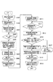
次に、このような格納容器102を用いて行われる複写機200の複写動作について図6に示すフローチャートを用いて説明する。
Next, a copying operation of the copying
ユーザは、他人に見せたくない原稿を複写しようとする場合、まず複写する原稿Dを格納容器102の原稿格納庫110に格納する(S202)。次に、格納容器102を自動原稿給送装置300にセット(接続)する(S203)。この際、第2シャッタ107は、バネに抗しながら下方回動し、これにより原稿格納庫110、読取原稿格納庫104及び成果物格納庫122の給送部側が開放される。
When the user wants to copy a document that he / she does not want to show to others, the user first stores the document D to be copied in the
次に、ユーザが操作部253に設けられた不図示のコピーボタンを押下すると(S204のY)、原稿格納庫110に格納された原稿Dが自動原稿給送装置300の給送部302によりプラテンガラス203上の画像読み取り位置に順次搬送される。そして、この位置で順次画像読取手段204により原稿が読取られる(S205)。
Next, when the user presses a copy button (not shown) provided on the operation unit 253 (Y in S204), the document D stored in the
ここで、このように画像読取手段204により順次読み取った原稿画像情報である読取原稿データは内部メモリ252に格納される(S206)。また、このように画像情報が読み取られた読取原稿D1は、排紙ローラ307により格納容器102の読取原稿格納庫104に格納される(S207)。
Here, the read original data which is the original image information sequentially read by the image reading means 204 is stored in the internal memory 252 (S206). Further, the read original D1 from which the image information has been read in this way is stored in the read
次に、このような原稿画像の読み取り及び読取原稿D1の格納を順次行い、やがて読取原稿D1の読取原稿格納庫104への格納が全て終了すると、操作部253に設けられた表示部には読取が終了したことを示す「読取終了」が表示される(S208)。そして、このような表示がなされると、ユーザは格納容器102を、自動原稿給送装置300から取り外す(S209)。
Next, the reading of the original image and the storage of the read original D1 are sequentially performed, and when the storage of the read original D1 in the read
なお、格納容器102を取り外すと、第2シャッタ107は、バネにより原稿格納庫110、読取原稿格納庫104及び成果物格納庫122の給紙部側を塞ぐ位置に復帰する。このため、格納容器102を取り外しても、読取原稿格納庫104から読取原稿D1が、また原稿格納庫110に原稿Dが残っている場合には、この原稿Dも落下しないようにすることができる。
When the
次に、自動原稿給送装置300から取り外された格納容器102を成果物積載部309にセットする(S210)。なお、格納容器102がセットされる際、格納容器102の第2シャッタ107の係合部106が、成果物積載部309に設けられている不図示の突起部に引っかかり、第2シャッタ107が開放される。この結果、原稿格納庫110、読取原稿格納庫104及び成果物格納庫122の排紙ローラ側が開放される。
Next, the
ここで、制御部250は、装着検知センサ251により格納容器102が成果物積載部309にセットされたかを判断する(S211)。なお、格納容器102が成果物積載部309にセットされていない場合には(S211のN)、他のユーザなどが他の複写処理や、ネットワークプリントを通常通り行う。
Here, the
一方、格納容器102が成果物積載部309にセットされていると判断した場合には(S211のY)、内部メモリ252に格納されている読取原稿データに基づき、画像形成を開始する(S212)。即ち、内部メモリ252に格納されている読取原稿データに基づき、露光手段230により感光ドラム221を露光し、感光ドラム表面に静電潜像を形成する。そして、この静電潜像を現像器223により現像して感光ドラム表面にトナー像を形成し、このトナー像をシートに転写した後、定着することによりシート上に画像が形成される。
On the other hand, when it is determined that the
次に、このようにトナー像が形成されたシート、即ち成果物S1を排紙ローラ226により、格納容器102の成果物格納庫122に格納する(S213)。この後、このように成果物S1が成果物格納庫122に順次格納され、やがて全ての成果物S1が格納されると、操作部253の表示部には、成果物S1が格納されたことを示す「格納終了」が表示される(S214)。そして、このような表示が行われると、ユーザは格納容器102を成果物積載部309から取り外す(S215)。
Next, the sheet on which the toner image is formed, that is, the product S1 is stored in the
なお、このように格納容器102を取り外した後、ユーザは第1シャッタ105を開放して読取原稿格納庫104内の読取原稿D1を取り出し、更に成果物S1を成果物格納庫122の第2の蓋120を開放することにより取り出す。
After removing the
このように、原稿画像を読み取る際には、原稿Dを格納した格納容器102を自動原稿給送装置300に取り付け、自動原稿給送装置300により原稿Dをスキャナ部202に搬送すると共に読取原稿D1を読取原稿格納庫104に格納する。また、成果物S1を排出する際には、格納容器102をシート排出部271に着脱自在に取り付け、成果物S1を成果物格納庫122に格納する。
As described above, when reading a document image, the
これにより、複写操作を実際に行っている際に、複写しようとしている原稿の覗き見を防止し、自動原稿給送装置300に置かれている原稿や、成果物を実際に取り出して持ち運ぶ際の安全性を保護することができる。また、複写する原稿の置き忘れ、成果物の混載、他人による成果物の持ち去り等から発生する情報漏洩を防止することができる。
This prevents peeping of the manuscript to be copied when the copying operation is actually performed, and when the manuscript placed on the
つまり、原稿画像を読み取る際には、格納容器102を自動原稿給送装置300に取り付け、成果物が排出される際には格納容器102を成果物積載部309に取り付けることにより、原稿と成果物を同一の格納容器102に格納することができる。これにより、原稿及び成果物の秘匿性を確保することができる。
That is, when reading a document image, the
ところで、これまで説明したように本実施の形態においては、格納容器102を自動原稿給送装置300にセットした後、原稿画像を読み取り、この後、格納容器102を自動原稿給送装置300から取り外して成果物積載部309にセットするようにしている。
As described above, in the present embodiment, after the
しかし、このように構成した場合、ユーザが誤って、自動原稿給送装置300から取り外した格納容器102と異なる格納容器102を成果物積載部309にセットしてしまう場合がある。
However, in such a configuration, the user may accidentally set a
そこで、このように自動原稿給送装置300から取り外した格納容器102と異なる格納容器102が成果物積載部309にセットされた場合には、内部メモリに格納されているデータに基づく画像形成を行わないようにする必要がある。
Therefore, when a
次に、このような自動原稿給送装置300から取り外した格納容器と異なる格納容器が成果物積載部309にセットされた場合には、内部メモリに格納されているデータに基づく画像形成を行わないようにした本発明の第2の実施の形態について説明する。
Next, when a storage container different from the storage container removed from the
図7は、本実施の形態に係る画像形成装置の一例である複写機に着脱自在に装着される格納容器102の斜視図である。図7において、既述した図2と同一符号は、同一または相当部分を示している。
FIG. 7 is a perspective view of the
図7において、130は格納容器本体102aの上面に設けられ、格納容器102の個別識別を行うための被識別部の一例としての凹部である。また、成果物積載部309及び自動原稿給送装置300には、格納容器102を装着した際、この凹部130の位置を検知する既述した図5に示す第1識別センサ254及び第2識別センサ255が、それぞれ設けられている。
In FIG. 7,
なお、この凹部130と第1識別センサ254とにより、格納容器102を識別する第1識別部が構成され、この凹部130と第2識別センサ255とにより、格納容器102を識別する第2識別部が構成される。
The
制御部250は、格納容器102が自動原稿給送装置300にセットされたときに第1識別センサ254からの信号に基づき、格納容器102の個別認識を行う。また、格納容器102が成果物積載部309にセットされたとき、第2識別センサ255からの信号に基づき、自動原稿給送装置300から取り外した格納容器102と同一であるかを判断するようにしている。
The
そして、成果物積載部309にセットされた格納容器102が、自動原稿給送装置300から取り外された格納容器102と同一であると判断したときは、読み取られた画像を形成するために、画像形成プロセスを開始するようにしている。
When it is determined that the
次に、このような本実施の形態に係る格納容器102を用いて行われる複写機200の複写動作について図8に示すフローチャートを用いて説明する。
Next, the copying operation of the copying
ユーザは、他人に見せたくない原稿を複写しようとする場合、まず複写する原稿Dを格納容器102の原稿格納庫110に格納し(S502)、次に格納容器102を自動原稿給送装置300にセット(接続)する(S503)。この際、第2シャッタ107は、バネに抗しながら下方回動し、これにより原稿格納庫110、読取原稿格納庫104及び成果物格納庫122の給送部側が開放される。
When the user wants to copy a document that he / she does not want to show to others, first the document D to be copied is stored in the
ここで、格納容器102がセットされると、制御部250は、自動原稿給送装置300に設けられている第1識別センサ254により、自動原稿給送装置300にセットされた格納容器102の個別認識信号を読み取り、内部メモリ252に記憶する(S504)。次に、ユーザが操作部253に設けられたコピーボタンを押下すると(S505のY)、原稿格納庫110に格納された原稿Dが自動原稿給送装置300の給送部302によりプラテンガラス203上の画像読み取り位置に搬送される。
When the
そして、この位置で画像読取手段204により原稿画像を読み取り、読み取った画像データを内部メモリ252に格納容器102の個別識別信号と関連付けた状態で格納する(S506)。また、このように画像情報が読み取られた読取原稿D1は、排紙ローラ307により格納容器102の読取原稿格納庫104に格納される(S507)。
The original image is read by the image reading means 204 at this position, and the read image data is stored in the
次に、このような原稿画像の読み取り及び読取原稿D1の格納を順次行い、やがて読取原稿D1の読取原稿格納庫104への格納が全て終了すると、操作部253に設けられた表示部には読取が終了したことを示す「読取終了」が表示される(S508)。そして、このような操作部の表示の後、ユーザは格納容器102を、自動原稿給送装置300から取り外す(S509)。
Next, the reading of the original image and the storage of the read original D1 are sequentially performed, and when the storage of the read original D1 in the read
なお、このように格納容器102を取り外すと、第2シャッタ107は、バネにより原稿格納庫110、読取原稿格納庫104及び成果物格納庫122の一側を塞ぐ位置に復帰する。このため、格納容器102を取り外しても、読取原稿格納庫104から読取原稿D1が、また原稿格納庫110に原稿Dが残っている場合には、この原稿Dも落下しないようにすることができる。
When the
次に、自動原稿給送装置300から取り外された格納容器102を成果物積載部309にセットする(S510)。なお、このように格納容器102がセットされる際、第2シャッタ107が開放され、この結果、原稿格納庫110、読取原稿格納庫104及び成果物格納庫122の排紙ローラ側が開放される。
Next, the
ここで、制御部250は、装着検知センサ251により格納容器102が成果物積載部309にセットされたかを判断する(S511)。なお、格納容器102が成果物積載部309にセットされていない場合には(S511のN)、他のユーザなどが他の複写処理や、ネットワークプリントを通常通り行う。
Here, the
一方、格納容器102が成果物積載部309にセットされていると判断した場合には(S511のY)、次に第2識別センサ255により、成果物積載部309に挿入された格納容器102の個別識別信号を読み取る(S512)。そして、内部メモリ252に、この格納容器102の個別識別信号に一致した読み取り原稿データが有るかを確認する(S513)。
On the other hand, if it is determined that the
ここで、個別識別信号と一致した読み取り原稿データが有る場合には(S513のY)、内部メモリ252のデータに基づき、画像形成が開始され(S514)、シートにトナー像が形成される。そして、このようにトナー像が形成されたシート、即ち成果物S1を排紙ローラ226により、格納容器102の成果物格納庫122に格納する(S515)。
If there is read original data that matches the individual identification signal (Y in S513), image formation is started based on the data in the internal memory 252 (S514), and a toner image is formed on the sheet. The sheet on which the toner image is thus formed, that is, the product S1 is stored in the
なお、このように成果物S1が格納容器102に格納され、やがて全ての成果物S1が格納されると、操作部253の表示部には、成果物が格納されたことを示す「格納終了」が表示される(S516)。そして、このような表示が行われると、ユーザは格納容器102を成果物積載部309から取り外す(S518)。
When the product S1 is stored in the
なお、個別識別信号と一致した読み取り原稿データが無い場合には(S513のN)、操作部253の表示部に「終了」表示を行い(S517)、格納容器102を成果物積載部309より取り外し(S518)、画像形成を終了する。
If there is no read original data that matches the individual identification signal (N in S513), “End” is displayed on the display unit of the operation unit 253 (S517), and the
以上説明したように、本実施の形態においては、格納容器102を識別する第1及び第2識別部を設け、成果物積載部309にセットされた格納容器102と自動原稿給送装置300にセットされた格納容器102とが同一か否かを判断するようにしている。そして、同一でないと判断した時には、操作部に同一でないとの旨の表示を行うと共に、内部メモリ252に記憶されている原稿データによる画像の形成を行わないようにしている。言い換えれば、第1及び第2識別部の識別結果が同じ場合に画像形成動作を行うよう画像形成部220を制御している。
As described above, in the present embodiment, the first and second identification units for identifying the
このように、本実施の形態においては、格納容器102の認識を行い自動原稿給送装置300にセットされた格納容器102と同一の格納容器102でしか成果物を取り出すことができないようにしている。これにより、他の画像形成による成果物の混載や所有者以外の者の成果物の持ち去りによる情報漏洩を防止することができ、原稿及び成果物の秘匿性を確保することができる。
As described above, in the present embodiment, the
なお、本実施の形態においては、識別部を凹部とセンサとにより構成したが、識別部の構成は、これに限らない。例えば、識別部を、格納容器102に埋め込んだメモリチップ等と、自動原稿給送装置300及び成果物積載部309に設けられ、格納容器102に埋め込まれたメモリチップを読み込むセンサとにより構成しても良い。
In the present embodiment, the identification unit is configured by the recess and the sensor, but the configuration of the identification unit is not limited to this. For example, the identification unit includes a memory chip embedded in the
なお、本実施の形態のように識別部を設けた場合、ユーザが予め原稿の読み取りを行って内部メモリ252に原稿データを記録・格納しておき、この後、任意の時に格納容器102を成果物積載部309にセットすることで、成果物を出力させることができる。そして、このような方法を用いた場合、複数のユーザが、それぞれ異なる格納容器を用いた場合でも、機密保持を行いつつ同時に成果物を得ることができる。
When the identification unit is provided as in the present embodiment, the user reads the document in advance and records and stores the document data in the
次に、このような複数のユーザが、それぞれ異なる格納容器を使用することができるようにした本発明の第3の実施の形態について説明する。 Next, a description will be given of a third embodiment of the present invention in which a plurality of such users can use different storage containers.
図9は、このような本実施の形態に係る格納容器を用いて行われる画像形成装置の一例である複写機の複写動作を説明するフローチャートである。 FIG. 9 is a flowchart for explaining a copying operation of a copying machine as an example of an image forming apparatus performed using the storage container according to this embodiment.
ここで、複数のユーザが、それぞれ異なる格納容器を使用する場合、メインルーチンがスタートされると、まず格納容器102が自動原稿給送装置300にセット(接続)されているかを判別する(S602)。次に、格納容器102が成果物積載部309にセット(接続)されているかを判別し(S603)、次に格納容器102が接続(セット)されて無い状態で複写操作が行われたかを判別する(S604)。
Here, when a plurality of users use different storage containers, when the main routine is started, it is first determined whether the
そして、自動原稿給送装置300に格納容器102がセット(接続)されているかの判別において(S602)、格納容器102の接続が確認された場合には(S602のY)、図10に示す格納容器原稿読み出しルーチン(S610)へ分岐する。
Then, in determining whether or not the
また、格納容器102が成果物積載部309セット(接続)されているかの判別において(S603)、格納容器102の接続が確認された場合には、図10に示す格納容器成果物出力ルーチン(S620)へ分岐する。なお、格納容器原稿読み出しルーチン(S610)及び格納容器成果物出力ルーチン(S620)へ分岐しない状態で、複写機にて操作が行われた際には、通常の複写機の動作が行われたと判別して不図示の複写動作ルーチンへ分岐する。
Further, in determining whether the
次に、図10に示す格納容器原稿読み出しルーチンについて説明する。 Next, the storage container document reading routine shown in FIG. 10 will be described.
制御部は、第1識別センサ254自動原稿給送装置300にセットされた格納容器102の個別認識信号を読み取り、内部メモリに記憶する(S611)。次に、自動原稿給送装置300の給送部302によりプラテンガラス203上への原稿搬送を行う。この後、画像読取手段204により、原稿画像を順次読み取り、読み取ったデータを内部メモリに格納容器の個別識別信号と関連づけされた状態で格納する(S612)。
The control unit reads the individual recognition signal of the
次に、このように順次画像情報が読み取られた読取原稿D1は、排紙ローラ307により格納容器102の読取原稿格納庫104に格納される(S613)。この後、読取原稿D1の読取原稿格納庫104への格納が全て終了すると、操作部に設けられた表示部には読取が終了したことを示す「読取終了」が表示される(S614)。そして、このような操作部の表示の後、ユーザは格納容器102を、自動原稿給送装置300から取り外す(S615)。そして、このような動作が終了した後、メインルーチンへ戻る。
Next, the read original D1 from which the image information is sequentially read in this manner is stored in the read
次に、格納容器成果物出力ルーチン(S620)について説明を行う。この場合、自動原稿給送装置300から取り外された格納容器102が成果物積載部309にセットされると、制御部250は、第2識別センサ255により、成果物積載部309に挿入された格納容器102の個別識別信号を読み取る(S621)。そして、内部メモリに格納されている格納容器個別識別信号と関連付けられた読み取り画像データが有るかを確認する(S622)。
Next, the storage container product output routine (S620) will be described. In this case, when the
ここで、個別識別信号と関連付けられた読み取り画像データが有る場合には(S622のY)、内部メモリのデータに基づき、画像形成が開始され(S623)、シートにトナー像が形成される。 If there is read image data associated with the individual identification signal (Y in S622), image formation is started based on the data in the internal memory (S623), and a toner image is formed on the sheet.
次に、このようにトナー像が形成された成果物S1を排紙ローラ226により、格納容器102の成果物格納庫122に格納する(S624)。ここで、このように成果物S1が格納容器102に格納され、やがて全ての成果物S1が格納されると、操作部の表示部には、成果物が格納されたことを示す「格納終了」が表示される(S625)。そして、このような表示が行われると、ユーザは格納容器102を成果物積載部309から取り外す(S627)。
Next, the product S1 on which the toner image is thus formed is stored in the
一方、個別識別信号と関連付けられた読み取り画像データが無い場合には(S622のN)、操作部の表示部に「終了」表示を行い(S626)、格納容器102を成果物積載部309より取り外し(S627)、メインルーチン(S601)へ戻る。
On the other hand, when there is no read image data associated with the individual identification signal (N in S622), “end” is displayed on the display unit of the operation unit (S626), and the
このように構成することにより、格納容器102に対応した原稿からの成果物のみ、その格納容器102に格納されるようになるので、他者が誤って成果物を取り出すことを防ぐことができ、原稿及び成果物の秘匿性を確保することができる。また、本実施の形態のように構成することにより、一つの複写機(画像形成装置)で複数の格納容器を自在に使い分けることができ、利便性が向上する。
By configuring in this way, since only the deliverables from the manuscript corresponding to the
なお、これまでの説明においては、原稿と読取原稿を分離して格納することができるよう、図2に示すような3層構造の格納容器102を用いたが、本発明は、これに限らない。例えば、格納容器102を、図11に示すように原稿及び読取原稿D1を同一の第1の格納部104Aに格納するようにして二層式の構成としても良い。この構成の場合、第1の格納部104Aへの原稿の格納及び読取原稿Dの取り出しは、第2シャッタ107を開放することにより行う。
In the above description, the
また、この格納容器102に機械的あるいは電子的な錠前手段を設けることにより、格納容器102に格納された原稿及び成果物の保護が可能となる。
Further, by providing the
102 格納容器
103 第1の蓋
104 読取原稿格納庫
104A 第1の格納部
105 第1シャッタ
107 第2シャッタ
110 原稿格納庫
120 第2の蓋
122 成果物格納庫
130 凹部
200 複写機
200A 複写機本体
201 画像読取装置
202 スキャナ部
220 画像形成部
250 制御部
251 装着検知センサ
252 内部メモリ
253 操作部
254 第1識別センサ
255 第2識別センサ
270 排紙トレイ
271 シート排出部
300 自動原稿給送装置(ADF)
309 成果物積載部
D 原稿
D1 読取原稿
S シート
S1 成果物
DESCRIPTION OF
309 Product stacking unit D Document D1 Scanned document S Sheet S1 Product
Claims (8)
原稿及び前記画像読取部により画像が読み取られた後の画像読取済み原稿を格納する原稿格納部と、前記画像形成部によって画像が形成されたシートを格納するシート格納部とを有する格納部材を着脱自在に備え、
前記格納部材の前記原稿格納部に格納された原稿を前記原稿搬送部が前記画像読取部に搬送すると共に画像読取済み原稿を前記原稿格納部に格納し、前記画像形成部によって画像が形成されたシートを装着位置が変更された前記格納部材の前記シート格納部に格納することを特徴とする画像形成装置。 An image reading unit that reads an image of a document, a document conveying unit that conveys the document to the image reading unit, and an image forming unit that forms an image on a sheet based on image information read by the image reading unit In the image forming apparatus,
A storage member including a document storage unit that stores a document and an image-read document after the image is read by the image reading unit, and a sheet storage unit that stores a sheet on which an image is formed by the image forming unit is attached and detached. Freely prepared,
The document stored in the document storage unit of the storage member is transported by the document transport unit to the image reading unit, and the image-read document is stored in the document storage unit, and an image is formed by the image forming unit. An image forming apparatus, wherein a sheet is stored in the sheet storage portion of the storage member whose mounting position is changed .
原稿画像を読み取る際には、前記格納部材を、前記原稿格納部に格納された原稿を搬送して画像読取済み原稿を前記原稿格納部に格納するために前記原稿搬送部に取り付け、画像が形成されたシートを排出する際には、前記格納部材を、排出されるシートを前記シート格納部に格納するよう前記シート排出部に取り付けることを特徴とする請求項1記載の画像形成装置。 A sheet discharge unit for discharging a sheet on which an image is formed by the image forming unit;
When reading a document image, the storage member is attached to the document transport unit to transport the document stored in the document storage unit and store the image-read document in the document storage unit, thereby forming an image. The image forming apparatus according to claim 1, wherein when the discharged sheet is discharged, the storage member is attached to the sheet discharge portion so as to store the discharged sheet in the sheet storage portion.
前記画像形成部の画像形成動作を制御する制御部と、を備え、
前記制御部は、前記検知部から検知信号が入力されると、前記画像読取部により読み取った原稿情報に基づき画像形成動作を行うよう前記画像形成部を制御することを特徴とする請求項2記載の画像形成装置。 A detection unit for detecting that the storage member is attached to the sheet discharge unit;
A control unit for controlling an image forming operation of the image forming unit,
3. The control unit according to claim 2, wherein when the detection signal is input from the detection unit, the control unit controls the image forming unit to perform an image forming operation based on document information read by the image reading unit. Image forming apparatus.
前記シート排出部に着脱自在に取り付けられた前記格納部材を識別する第2識別部と、を備え、
前記制御部は、前記第1識別部と前記第2識別部の識別結果が同じ場合に画像形成動作を行うよう前記画像形成部を制御することを特徴とする請求項3記載の画像形成装置。 A first identification unit for identifying the storage member detachably attached to the document conveying unit;
A second identification unit for identifying the storage member detachably attached to the sheet discharge unit,
The image forming apparatus according to claim 3, wherein the control unit controls the image forming unit to perform an image forming operation when the identification results of the first identification unit and the second identification unit are the same.
原稿及び前記画像読取部により画像が読み取られた後の画像読取済み原稿を格納する原稿格納部と、前記画像形成部によって画像が形成された後、前記シート排出部により排出されるシートを格納するシート格納部とを有し、前記シート格納部にシートを格納する際には、装着位置が変更されることを特徴とする格納部材。 An image reading unit that reads an image of a document, a document transport unit that transports the document to the image reading unit, an image forming unit that forms an image on a sheet based on image information read by the image reading unit, and the image forming unit A storage member that is detachably provided in an image forming apparatus main body including a sheet discharge unit that discharges a sheet on which an image is formed by the unit,
A document storage unit that stores a document and an image-read document after the image is read by the image reading unit, and a sheet that is discharged by the sheet discharge unit after the image is formed by the image forming unit. storing member possess a sheet storage unit, when storing the sheets in the sheet storage unit, characterized in that the mounting position is changed.
Priority Applications (2)
| Application Number | Priority Date | Filing Date | Title |
|---|---|---|---|
| JP2008149536A JP5072720B2 (en) | 2008-06-06 | 2008-06-06 | Storage member and image forming apparatus |
| US12/476,705 US8199375B2 (en) | 2008-06-06 | 2009-06-02 | Image forming system and image reading apparatus |
Applications Claiming Priority (1)
| Application Number | Priority Date | Filing Date | Title |
|---|---|---|---|
| JP2008149536A JP5072720B2 (en) | 2008-06-06 | 2008-06-06 | Storage member and image forming apparatus |
Publications (3)
| Publication Number | Publication Date |
|---|---|
| JP2009296448A JP2009296448A (en) | 2009-12-17 |
| JP2009296448A5 JP2009296448A5 (en) | 2011-07-21 |
| JP5072720B2 true JP5072720B2 (en) | 2012-11-14 |
Family
ID=41544181
Family Applications (1)
| Application Number | Title | Priority Date | Filing Date |
|---|---|---|---|
| JP2008149536A Expired - Fee Related JP5072720B2 (en) | 2008-06-06 | 2008-06-06 | Storage member and image forming apparatus |
Country Status (1)
| Country | Link |
|---|---|
| JP (1) | JP5072720B2 (en) |
Families Citing this family (1)
| Publication number | Priority date | Publication date | Assignee | Title |
|---|---|---|---|---|
| JP7099145B2 (en) * | 2018-07-31 | 2022-07-12 | 株式会社リコー | Image forming device |
Family Cites Families (4)
| Publication number | Priority date | Publication date | Assignee | Title |
|---|---|---|---|---|
| JPS4963441A (en) * | 1972-10-17 | 1974-06-19 | ||
| JPH0616344A (en) * | 1992-07-03 | 1994-01-25 | Nisca Corp | Automatic document transporting device |
| JP2000233547A (en) * | 1999-02-17 | 2000-08-29 | Sharp Corp | Imaging apparatus |
| JP2001334722A (en) * | 2000-05-25 | 2001-12-04 | Sharp Corp | Image forming device |
-
2008
- 2008-06-06 JP JP2008149536A patent/JP5072720B2/en not_active Expired - Fee Related
Also Published As
| Publication number | Publication date |
|---|---|
| JP2009296448A (en) | 2009-12-17 |
Similar Documents
| Publication | Publication Date | Title |
|---|---|---|
| JP2007300385A (en) | Original reading apparatus, image forming apparatus, and original reading system | |
| JP2008076851A (en) | Image recorder | |
| JP5072720B2 (en) | Storage member and image forming apparatus | |
| JP4404059B2 (en) | Image forming apparatus | |
| JP5436000B2 (en) | Image forming apparatus | |
| JP2006025255A (en) | Image reader | |
| JP3964805B2 (en) | Image processing apparatus and image forming apparatus | |
| JP5207835B2 (en) | Image forming apparatus | |
| JP2006239896A (en) | Image forming apparatus | |
| JP2013232712A (en) | Image formation device | |
| JP2006108796A (en) | Image reader and image forming apparatus with image reader | |
| JP2008017193A (en) | Image processing apparatus | |
| US8199375B2 (en) | Image forming system and image reading apparatus | |
| JP3840775B2 (en) | Communication terminal device | |
| US10609257B2 (en) | Image processing apparatus with sheet removal monitoring for sheets with protection-target image | |
| JP4518201B2 (en) | Image forming apparatus | |
| JP2000309467A (en) | Image reading and recording device | |
| JP2008129368A (en) | Image forming apparatus | |
| JP2001296784A (en) | Original reading and recording device | |
| JP2005340894A (en) | Original reading apparatus | |
| JP2000302274A (en) | Image reading and recording device and image recorder | |
| JP6121318B2 (en) | Image forming apparatus | |
| JP2021089343A (en) | Image reading device, image forming apparatus, and image reading system | |
| JP2005020663A (en) | Automatic double-sided image forming apparatus | |
| JP2023173185A (en) | Document conveyance device, image reading apparatus and compound machine |
Legal Events
| Date | Code | Title | Description |
|---|---|---|---|
| A521 | Request for written amendment filed |
Free format text: JAPANESE INTERMEDIATE CODE: A523 Effective date: 20110601 |
|
| A621 | Written request for application examination |
Free format text: JAPANESE INTERMEDIATE CODE: A621 Effective date: 20110601 |
|
| RD05 | Notification of revocation of power of attorney |
Free format text: JAPANESE INTERMEDIATE CODE: A7425 Effective date: 20120125 |
|
| RD03 | Notification of appointment of power of attorney |
Free format text: JAPANESE INTERMEDIATE CODE: A7423 Effective date: 20120203 |
|
| A977 | Report on retrieval |
Free format text: JAPANESE INTERMEDIATE CODE: A971007 Effective date: 20120423 |
|
| A131 | Notification of reasons for refusal |
Free format text: JAPANESE INTERMEDIATE CODE: A131 Effective date: 20120501 |
|
| A521 | Request for written amendment filed |
Free format text: JAPANESE INTERMEDIATE CODE: A523 Effective date: 20120629 |
|
| TRDD | Decision of grant or rejection written | ||
| A01 | Written decision to grant a patent or to grant a registration (utility model) |
Free format text: JAPANESE INTERMEDIATE CODE: A01 Effective date: 20120724 |
|
| A01 | Written decision to grant a patent or to grant a registration (utility model) |
Free format text: JAPANESE INTERMEDIATE CODE: A01 |
|
| A61 | First payment of annual fees (during grant procedure) |
Free format text: JAPANESE INTERMEDIATE CODE: A61 Effective date: 20120821 |
|
| FPAY | Renewal fee payment (event date is renewal date of database) |
Free format text: PAYMENT UNTIL: 20150831 Year of fee payment: 3 |
|
| LAPS | Cancellation because of no payment of annual fees |