JP5068552B2 - Prefetch method and cache mechanism unit - Google Patents
Prefetch method and cache mechanism unit Download PDFInfo
- Publication number
- JP5068552B2 JP5068552B2 JP2007024090A JP2007024090A JP5068552B2 JP 5068552 B2 JP5068552 B2 JP 5068552B2 JP 2007024090 A JP2007024090 A JP 2007024090A JP 2007024090 A JP2007024090 A JP 2007024090A JP 5068552 B2 JP5068552 B2 JP 5068552B2
- Authority
- JP
- Japan
- Prior art keywords
- entry
- memory address
- value
- index
- cache
- Prior art date
- Legal status (The legal status is an assumption and is not a legal conclusion. Google has not performed a legal analysis and makes no representation as to the accuracy of the status listed.)
- Expired - Fee Related
Links
Images


Landscapes
- Memory System Of A Hierarchy Structure (AREA)
Description
本発明は、プリフェッチ方法、及びキャッシュ機構用ユニットに関する。 The present invention relates to a prefetch method and a cache mechanism unit.
近年情報処理装置の高速化の進展が著しい。しかしながら、CPUの演算処理速度に比べて、メモリの動作速度は遅い。そして、メモリの動作速度は、CPUとメモリとを含んで構成されるシステム全体の高速化を妨げる要因となっている。 In recent years, progress in speeding up of information processing apparatuses has been remarkable. However, the operation speed of the memory is slower than the calculation processing speed of the CPU. The operating speed of the memory is a factor that hinders the speeding up of the entire system including the CPU and the memory.
上述の問題に対する対策として、CPUにキャッシュ機構を付加する技術が知られている。キャッシュ機構は、CPUとメモリとの間のアクセスを監視し、そのアクセス情報を記憶する。そして、再度CPUからメモリにアクセスがあったとき、動作速度の遅いメモリの代わりに動作速度の速いキャッシュによりCPUにデータが連絡される。 As a countermeasure against the above problem, a technique for adding a cache mechanism to a CPU is known. The cache mechanism monitors access between the CPU and the memory and stores the access information. When the memory is accessed again from the CPU, data is communicated to the CPU by a cache having a high operating speed instead of a memory having a low operating speed.
キャッシュは、小容量の記憶装置で構成され、その動作速度は高速である。しかし、キャッシュの容量は小さいため、メモリに比較して記憶できるデータ容量が少ない。従って、キャッシュには、メモリにあるデータのうち、必要となるデータのみが保持されることように構成する(特許文献1乃至4参照、非特許文献1参照)。
ここで、まず、一般的なプリフェッチの方法として、ストライドによるプリフェッチについて説明する。なお、ストライドによるプリフェッチでは、2回のキャッシュミスに基づいて、その差分値を得る。つまり、1回目のキャッシュミス時のメモリのアドレス(以下、単にメモリアドレスとする)から2回目のキャッシュミス時のメモリアドレスの差分値を得る。そして、2回目のキャッシュミス時のメモリアドレスに、この差分値を加算する。そして、この加算値に対応するメモリアドレスにあるデータをキャッシュにフェッチする。 Here, first, prefetch by stride will be described as a general prefetch method. In the prefetch by stride, the difference value is obtained based on two cache misses. That is, the difference value of the memory address at the second cache miss is obtained from the memory address at the first cache miss (hereinafter simply referred to as a memory address). Then, this difference value is added to the memory address at the time of the second cache miss. Then, the data at the memory address corresponding to the added value is fetched into the cache.
図14に、ストライドによるプリフェッチのプリフェッチ機構510を示す。プリフェッチ機構510は、CPU500、メモリ501、キャッシュコントローラ502、キャッシュ503、ValueHistoryTable504、を有する。CPU500は、演算処理を実行する。メモリ501には、あらかじめデータが格納される。キャッシュ503には、プリフェッチされたデータが格納される。キャッシュコントローラ502は、CPU500とメモリ501との間のアクセスを監視し、そのアクセス情報をValueHistoryTable504に書き込む。キャッシュコントローラ502は、ValueHistoryTable504に書き込まれた情報に基づいて、適切にプリフェッチを行う。
FIG. 14 shows a
図15に、ストライドによるプリフェッチにおいて、配列式のプログラムが実行される場合の説明図を示す。なお、配列式のデータ構造のプログラムでは、プログラムの実行に伴って、順次一定数で増加するメモリアドレスにアクセスされる。 FIG. 15 shows an explanatory diagram when an array-type program is executed in prefetching by stride. Note that in a program having an array type data structure, memory addresses that sequentially increase by a fixed number are accessed as the program is executed.
図15に示すように、ステップ4において、1回目のキャッシュミスが発生する。キャッシュコントローラ502は、キャッシュミス発生時にアクセスされたメモリアドレス10を、ValueHistoryTable504のValueに書き込む。また、キャッシュコントローラ502は、ValueHistoryTable504のStateを1回目とする。
As shown in FIG. 15, in
ステップ9において、2回目のキャッシュミスが発生する。キャッシュコントローラ502は、ValueHistoryTable504のStateから、このキャッシュミスが2回目であることを判断する。そして、今回のキャッシュミス時のメモリアドレス20からValueHistoryTable504のValueに設定された1回目のキャッシュミスが発生したメモリアドレス10を減算した値(差分値)10を求める。キャッシュコントローラ502は、ValueHistoryTable504のStrideに求めた差分値10を設定し、そのStateを2回目とする。また、キャッシュコントローラ502は、今回のメモリアドレス20にValueHistoryTable504のStrideに設定された値10を加えた30に対応するメモリアドレス30にあるデータをメモリ501からキャッシュ503にフェッチする。
In
ステップ14において、メモリアドレス30にアクセスがある。ステップ9での処理によって、キャッシュ503には、あらかじめメモリアドレス30にあるデータがある。よって、ステップ14では、メモリ501にアクセスする必要はなく、キャッシュ503にアクセスすればよい。つまり、キャッシュヒットが得られる。なお、ここでも、キャッシュコントローラ502は、ValueHistoryTable504のStateから3回目であることを判断する。そして、キャッシュコントローラ502は、今回のアドレス30にStrideの10を加えたアドレス40にあるデータをメモリ501からキャッシュ503にプリフェッチする。
In
このようにして、それ以降においても、ステップ14と同様に、キャッシュヒットを得ることができる。
In this way, cache hits can be obtained after that as well as in
しかしながら、プログラムのデータ構造には、上述の配列式のものではないリンク式のものもある。ストライドによるプリフェッチでは、配列式のプログラムに対しては有効である。しかし、リンクリスト式のプログラムに対しても有効なものであるとは言いがたい。以下、この点について説明する。 However, some of the program data structures are linked rather than the above-described array type. The prefetch by stride is effective for an array-type program. However, it is difficult to say that it is effective for linked list type programs. Hereinafter, this point will be described.
図16に、リンクリスト式のプログラムのリストセルの配置サンプルを示す。図16に示すように、不定数のリストセル1〜5が、矢印に示すように、互いにリンクされて管理される。リストセルの実行は、そのリストセルの順番に従って行われる。ただし、リストセルの配列は、アクセスされるメモリアドレスに対応するものではない。ここでは、リストセルは、リストセル1、リストセル3、リストセル2、リストセル4、リストセル5の順番で配列されている。アクセスされるメモリアドレスのアドレス値は、リストセルの順番に従って、一定数で増加していない。
FIG. 16 shows a list cell arrangement sample of a linked list type program. As shown in FIG. 16, an infinite number of
なお、リンクリスト式のプログラムにおいては、一般的に、互いにリンクされたリンクリストの途中でリストセルの挿入や削除も可能となっている。したがって、上述のように、リストセルとメモリのアドレスとの対応関係が取れないことが起こりえる。このような場合には、上述のストライドによるプリフェッチでは、十分な効果は得られない。 In a linked list type program, it is generally possible to insert or delete list cells in the middle of linked lists linked to each other. Therefore, as described above, the correspondence between the list cell and the memory address may not be established. In such a case, sufficient effects cannot be obtained by prefetching using the above-mentioned stride.
図17に、ストライドによるプリフェッチにおいて、リンクリスト式のプログラムが実行される場合の説明図を示す。なお、実行されるプログラムは、図16に示された配置サンプルであることを前提とする。 FIG. 17 shows an explanatory diagram when a linked list type program is executed in prefetching by stride. It is assumed that the program to be executed is the arrangement sample shown in FIG.
図17に示すように、ステップ4において、1回目のキャッシュミスが発生する。キャッシュコントローラ502は、キャッシュミスが発生したときにアクセスされたメモリのアドレス10を、ValueHistoryTable504のValueに書き込む。また、キャッシュコントローラ502は、ValueHistoryTable504のStateを1回目とする。
As shown in FIG. 17, in
そして、ステップ9において、2回目のキャッシュミスが発生する。キャッシュコントローラ502は、ValueHistoryTable504のStateから、このキャッシュミスが2回目であることを判断する。そして、メモリアドレス30のアドレス値からValueHistoryTable504のValueに設定された1回目のキャッシュミスが発生したメモリアドレス10のアドレス値を減算した値(差分値)20を求める。そして、キャッシュコントローラ502は、ValueHistoryTable504のStrideに求めた差分値20を設定し、そのStateを2回目とする。また、キャッシュコントローラ502は、今回のアドレス30にValueHistoryTable504のStrideに設定された値20を加えて得たアドレス50にあるデータをメモリ501からキャッシュ503にフェッチする。
In
ステップ14において、アクセスされるメモリアドレスは20である。メモリ501のアドレス20にあるデータは、2回目のメモリへのアクセス時における処理によって、キャッシュ503にあらかじめ格納されていない。つまり、キャッシュミスが発生する。
In
その後、キャッシュコントローラ502は、ValueHistoryTable504のStateから3回目であることを判断する。そして、キャッシュコントローラ502は、今回のアクセスされたメモリのアドレス20からValueにある2回目のアドレス30を減算した−10をStrideに設定する。そして、Stateを2回目とする。そして、今回のアクセスされたメモリのアドレス20にStrideの−10を加算して得たアドレス10にフェッチしようとする。しかし、上述の1回目におけるメモリへのアクセスにより、そのデータが既にキャッシユにあるためフェッチは行わない。
Thereafter, the
上述の説明から明らかなように、従来のプリフェッチ方法では、リンクリスト式のプログラムに対応することはできなかった。 As is apparent from the above description, the conventional prefetch method cannot cope with a linked list type program.
本発明にかかるプリフェッチ方法は、コンピュータを用いたリンクリスト構造を含むプログラムを処理する際のプリフェッチ方法であって、前記プログラムを実行し、当該プログラムの命令の実行に伴ってアクセスされたメモリアドレスの順番を記憶する第1実行ステップと、前記第1実行ステップにより記憶された前記順番に基づいて、事前に取得されるべきデータをメモリからキャッシュにフェッチし、前記プログラムを実行する第2実行ステップと、を具備する。 A prefetch method according to the present invention is a prefetch method for processing a program including a linked list structure using a computer, wherein the program is executed and a memory address accessed along with execution of an instruction of the program is executed. A first execution step for storing an order; a second execution step for fetching data to be acquired in advance from a memory into a cache based on the order stored in the first execution step and executing the program; Are provided.
本発明にかかるプリフェッチ方法は、コンピュータを用いたリンクリスト構造を含むプログラムを処理する際のプリフェッチ方法であって、前記プログラムの実行は、複数のメモリアクセスを伴い、前記プログラムの第1実行時において、第2メモリアクセスがあったとき、当該第2メモリアクセス前に行われた第1メモリアクセス時のメモリアドレスをインデックスとするリンクリストキャッシュテーブルの第1エントリーに当該第2メモリアクセス時のメモリアドレスをインデックスとする前記リンクリストキャッシュテーブルの第2エントリーをリンクさせ、前記プログラムの第2実行時において、前記第1メモリアクセスに対応する第3メモリアクセスがあったとき、当該第3メモリアクセス時のメモリアドレスをインデックスとする前記第1エントリーにリンクされた前記第2エントリーのメモリアドレスを取得し、取得した当該メモリアドレスにあるデータをキャッシュにフェッチする。 A prefetch method according to the present invention is a prefetch method for processing a program including a linked list structure using a computer, and the execution of the program involves a plurality of memory accesses, and at the time of the first execution of the program When there is a second memory access, the memory address at the time of the second memory access is added to the first entry of the link list cache table using the memory address at the time of the first memory access performed before the second memory access as an index. When the second entry of the linked list cache table with the index is linked and there is a third memory access corresponding to the first memory access during the second execution of the program, Use memory address as index Gets the memory address of the second entry linked to the first entry, data is fetched into the cache in the acquired the memory address.
本発明にかかるキャッシュ機構用ユニットは、インデックスとしてのメモリアドレスを含んで構成されるエントリーを複数含むリンクリストキャッシュテーブルと、インデックスとしてのプログラムカウンタのカウント値、当該カウント値に対応するメモリアドレスを含んで構成されるエントリーを有するバススコアテーブルと、第1メモリアクセス時のメモリアドレスをインデックスとするリンクリストキャッシュテーブルの第1エントリーに、第2メモリアクセス時のメモリアドレスをインデックスとする前記リンクリストキャッシュテーブルの第2エントリーをリンクさせるディスクリプタコントローラと、を備える。 The cache mechanism unit according to the present invention includes a linked list cache table including a plurality of entries configured to include a memory address as an index, a count value of a program counter as an index, and a memory address corresponding to the count value. The bus score table having an entry configured by the above, and the linked list cache having the memory address at the time of the second memory access as an index in the first entry of the link list cache table having the memory address at the time of the first memory access as an index. A descriptor controller for linking the second entry of the table.
リンクリスト式のプログラムであっても、プリフェッチによるキャッシュヒットの確率を高めることができる。 Even in a linked list type program, the probability of a cache hit due to prefetch can be increased.
以下、図面を参照しつつ、本発明の実施の形態について説明する。なお、図面は簡略的なものであるから、この図面の記載を根拠として本発明の技術的範囲を狭く解釈してはならない。また、同一の要素には、同一の符号を付し、重複する説明は省略するものとする。また、図面は、もっぱら技術的事項の説明のためのものであり、図面に示された要素の正確な大きさ等は反映していない。 Hereinafter, embodiments of the present invention will be described with reference to the drawings. Since the drawings are simplified, the technical scope of the present invention should not be interpreted narrowly based on the description of the drawings. Moreover, the same code | symbol is attached | subjected to the same element and the overlapping description shall be abbreviate | omitted. Further, the drawings are only for explaining technical matters, and do not reflect the exact sizes of the elements shown in the drawings.
〔第1の実施の形態〕
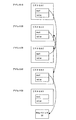
図1に、第1の実施の形態にかかるキャッシュ機構を説明するためのブロック図を示す。図1に示された演算処理機構100は、メモリ1、キャッシュコントローラ2、CPU3、キャッシュ4、プロファイラ5、プロファイルデータキュー6、ディスクリプタコントローラ7、バススコアテーブル8、リンクリストキャッシュテーブル9、キャッシュコントロールディスクリプタテーブル10、を備える。
[First Embodiment]
FIG. 1 is a block diagram for explaining the cache mechanism according to the first embodiment. 1 includes a
メモリ1には、実行されるプログラム、その他のデータが格納される。CPU3は、メモリ1に格納されたプログラムを実行する。また、メモリ1に格納されたデータにアクセスする。キャッシュコントローラ2は、メモリ1のデータをキャッシュ4にフェッチする。また、キャッシュコントローラ2は、CPU3−メモリ1間のアクセス、CPU3−キャッシュ4間のアクセスを監視したりする。本実施形態におけるキャッシュコントローラ2は、キャッシュコントロールディスクリプタテーブル10を参照して、適切なタイミングでプリフェッチする。従って、キャッシュ4には、プリフェッチにより必要なデータが格納される。
The
本実施形態においては、上述の、キャッシュコントローラ2、キュッシュ4、プロファイラ5、プロファイルデータキュー6、ディスクリプタコントローラ7、バススコアテーブル8、リンクリストキャッシュテーブル9、キャッシュコントロールディスクリプタテーブル10からキャッシュ機構が構成される。
In the present embodiment, the cache mechanism is composed of the
以下、キャッシュ機構に含まれる構成要素について説明する。 Hereinafter, components included in the cache mechanism will be described.
プロファイラ5は、メモリ1へのアクセスを監視し、メモリ1へのアクセスがないタイミングを検出する。そして、そのタイミングにおけるプログラムカウンタのカウント値(以下、単にPCとする)をCPU3から取得し、このPCをプリフェッチ可能PCとしてプロファイルデータキュー6に連絡する。
The
プロファイラ5は、時間計測タイマを持ち、メモリ1からキャッシュ4へのデータの読み込みにどれだけの時間がかかるのかを計測する。そして、この計測結果に基づいて、プリフェッチを行うタイミングを検出する。プロファイラ5は、メモリ1へのアクセスが終了したとき、時間計測タイマを動作させる。また、メモリ1へのアクセスが開始したとき、時間計測タイマを停止する。時間計測タイマが動作中であれば、時間計測タイマのカウント値をダウンカウントする。時間計測タイマのカウント値が0であれば、記憶済みのバス開放時のPCをプリフェッチ可能PCとして、プロファイルデータキュー6に連絡する。
The
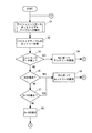
プロファイラ5により行われる処理を図2のフローチャートに示す。プロファイラ5は、メモリ1へのアクセスを監視する。プロファイラ5は、メモリ1へのアクセスの開始を検出する(S1)。アクセスの開始を検出したとき、プロファイラ5は、時間計測タイマを停止させる(S2)。そして、プロファイラ5は、そのアクセスが、キャッシュコントローラ2によるプリフェッチ時のアクセスかどうかを判断する(S3)。つまり、キャッシュコントロールディスクリプタテーブル10を参照して、キャッシュコントローラ2がメモリ1のデータをキャッシュ4にプリフェッチするときのアクセスであるか判断する。そして、プリフェッチ時のアクセスであれば、その時のPCをCPU3から取得し、そのPCをプリフェッチ可能PCとしてプロファイルデータキュー6に登録する(S4)。そして、再び、開始点Aに戻る。また、S3において、プリフェッチ時のアクセスではない場合にも、再び、開始点Aに戻る。
The processing performed by the
S1において、メモリ1へのアクセスの開始を検出しないとき、プロファイラ5は、メモリ1へのアクセスの終了を検出する(S5)。そして、メモリ1へのアクセスの終了を検出したとき、その時点でのPCをCPU3から取得し、そのPCを記憶する(S6)。また、時間計測タイマを動作させる(S7)。
When the start of access to the
S5において、メモリ1へのアクセスの終了を検出しないとき、プロファイラ5は、時間計測タイマが停止中かを確認する(S8)。時間計測タイマが停止中であれば、開始点Aに戻る。時間計測タイマが動作中であれば、ダウンカウントさせる(S9)。そして、時間計測タイマのカウント値が0であるかを確認する(S10)。時間計測タイマのカウント値が0であれば、記憶済みのPCをプロファイルデータキューにプリフェッチ可能PCとして登録する(S11)。そして、その時のPCをバス開放時のPCとする(S12)。そして、上述のS6、S7のステップを実行後、開始点Aに戻る。S10において、時間計測タイマのカウント値が0ではない場合には、開始点Aに戻る。
When the end of access to the
また、プロファイラ5は、ディスクリプタコントローラ7にCPU3からメモリ1にアクセスがあったときの情報を与える。
The
プロファイラ5は、命令サイクルカウンタを持ち、CPU3が命令を実行することを検出する度に、そのカウント値を1ずつ増加させる。また、プロファイラ5は、CPU3のレジスタから、CPU3によるメモリ1へのアクセス時(以下、メモリアクセス時と呼ぶこともある)のPC、メモリ1のアドレス(以下、メモリアドレスと呼ぶ)を取得する。そして、この取得した情報(PC、メモリアドレス)と上述の命令サイクルカウンタのカウント値(以下、単にカウント値と呼ぶこともある)とを、ディスクリプタコントローラ7に連絡する。
The
プロファイラ5により行われる処理を図3のフローチャートに示す。プロファイラ5は、CPU3が命令を1つ実行したことを検出する(S1)。そして、命令サイクルカウンタのカウント値を1増加させる(S2)。そして、そのCPU3において処理される命令が、CPU3からメモリ1へのアクセスであるのか確認する(S3)。CPU3からメモリ1へのアクセスである場合には、プロファイラ5は、ディスクリプタコントローラ7に情報を通知する(S4)。なお、通知される情報は、CPU3によるメモリアクセス時のPC、メモリアドレス、カウント値である。そして、開始点Aに戻る。S3においてメモリアクセスではない場合には、開始点Aに戻る。
The processing performed by the
上述のように、CPUからメモリへのアクセス時における所定の情報(PC、メモリアドレス、カウント値)が、プロファイラ5からディスクリプタコントローラ7に与えられる。換言すると、プロファイラ5は、CPUからメモリへのアクセスがあるたびに、所定の情報をディスクリプタコントローラ7に連絡する。そして、ディスクリプタコントローラ7は、プロファイラ5から与えられた情報に基づいて、リンクリストキャッシュテーブル9、バススコアテーブル8に後述の動作を行う。これによって、リンクリスト式のプログラム(リンクリスト構造を含むプログラム)であっても、キュッシュヒットを得る確率を高めることができる。
As described above, predetermined information (PC, memory address, count value) at the time of access from the CPU to the memory is given from the
ディスクリプタコントローラ7は、プロファイルデータキュー6に格納されたプリフェッチ可能PCをキャッシュコントロールディスクリプタテーブル10に連絡する。また、リンクリストキャッシュテーブル9を参照した結果に基づいて、プリフェッチされるべきメモリアドレスをキャッシュコントロールディスクリプタテーブル10に連絡する。
The
ここで、ディスクリプタコントローラ7の動作について詳述する前に、バススコアテーブル8、リンクリストキャッシュテーブル9について説明する。
Here, before describing the operation of the
図4に、バススコアテーブル8とリンクリストキャッシュテーブル9を説明する模式図を示す。図4に示すように、バススコアテーブル8は、エントリー8eを有する。エントリー8eは、インデックスとしてのPC、メモリアドレスを格納するフィールドを有する。なお、格納されるPCとメモリアドレスとは、プロファイラ5から同時に与えられたときのものである。なお、バススコアテーブル8のエントリーには、データの在/無、メモリアドレスの有効/無効、最終PC到達サイクル、再PC到達サイクル、といったフィールドもある。最終PC到達サイクルは、プロファイラ5から与えられた最後のカウント値である。再PC到達サイクルは、今回のプロファイラ5から与えられたカウント値から、前回の最終PC到達サイクルを減算した値である。
FIG. 4 is a schematic diagram illustrating the bus score table 8 and the link list cache table 9. As shown in FIG. 4, the bus score table 8 has an
図4に示すように、リンクリストキャッシュテーブル9は、エントリー9e1、9e2を有する。各エントリーは、インデックスとしてのメモリアドレス、リンクインデックスを有する。エントリー9e1のリンクインデックスに他のエントリー9e2のインデックスが設定されることにより、エントリー9e1とエントリー9e2とは互いに関連づけ(リンク)られる。なお、リンクインデックスには、他のエントリーのインデックスのほか、自身のエントリーのインデックスも設定される。また、各エントリーには、エントリーにおけるデータの有無、といった情報も格納される。 As shown in FIG. 4, the link list cache table 9 has entries 9e1 and 9e2. Each entry has a memory address as an index and a link index. By setting the index of the other entry 9e2 as the link index of the entry 9e1, the entry 9e1 and the entry 9e2 are associated (linked) with each other. In addition to the index of another entry, the index of its own entry is set as the link index. Each entry also stores information such as the presence or absence of data in the entry.
上述のように、CPU3によるメモリ1へのアクセスがあったとき、PC、メモリアドレス、カウント値が、プロファイラ5からディスクリプタコントローラ7に連絡される。そして、ディスクリプタコントローラ7は、リンクリストキャッシュテーブル9に次のように動作をする。
As described above, when the
ディスクリプタコントローラ7は、プロファイラ5から与えられたメモリアドレスに基づいて、そのメモリアドレスをインデックスとするリンクリストキャッシュテーブル9のエントリーを検索する。そして、取得したエントリーの状態に応じて、そのエントリーを次のように設定する。
Based on the memory address given from the
1−2−A:取得したエントリーにデータが無い場合。
ディスクリプタコントローラ7は、取得したエントリーのリンクインデックスに、取得したエントリー自身のインデックスを設定する。また、ディスクリプタコントローラ7は、プロファイラ5から与えられた情報に含まれるメモリアドレスを、キャッシュコントロールディスクリプタテーブル10にプリフェッチされるべきメモリアドレス(プリフェッチ用メモリアドレス)として連絡する。
1-2A: When there is no data in the acquired entry.
The
1−2−B:取得したエントリーにデータが在るが、プロファイラ5から与えられたメモリアドレスとは異なるアドレスである場合。
ディスクリプタコントローラ7は、取得したエントリーのリンクインデックスに、取得したエントリー自身のインデックスを設定する。また、ディスクリプタコントローラ7は、プロファイラ5から与えられたメモリアドレスを、キャッシュコントロールディスクリプタテーブル10にプリフェッチ用メモリアドレスとして連絡する。
1-2B: When there is data in the acquired entry, but the address is different from the memory address given from the
The
1−2−C:取得したエントリーにデータが在り、プロファイラ5から与えられたメモリアドレスと同じアドレスがある場合。
ディスクリプタコントローラ7は、取得したエントリーのリンクインデックスにより特定されるエントリーのメモリアドレスを、キャッシュコントロールディスクリプタテーブル10にプリフェッチ用メモリアドレスとして連絡する。換言すると、ディスクリプタコントローラ7は、プロファイラ5から与えられたメモリアドレスをキャッシュコントロールディスクリプタテーブル10に連絡しない。なお、取得したエントリーのリンクインデックスには、あらかじめ、後述の2−2−C−bの手順によって、他のエントリーとリンクされている。
1-2C: When there is data in the acquired entry and there is the same address as the memory address given from the
The
また、1−2−A、1−2−Bの場合、ディスクリプタコントローラ7は、バススコアテーブル8に次のように動作をする。ディスクリプタコントローラ7は、プロファイラ5から与えられたPCに基づいて、そのPCをインデックスとするバススコアテーブル8のエントリーを取得する。そして、取得したエントリーを次のように設定する。
In the case of 1-2A and 1-2B, the
2−2−A:バススコアテーブル8のエントリーにデータが無い場合。
プロファイラ5から与えられたメモリアドレスを、そのエントリーのメモリアドレスに設定する。また、プロファイラ5から与えられたカウント値を、そのエントリーの最終PC到達サイクルに設定する。また、そのエントリーの再PC到達サイクルを0とする。
2-2A: When there is no data in the entry of the bus score table 8.
The memory address given from the
2−2−B:バススコアテーブル8のエントリーにデータが在り、再PC到達サイクル0の場合。
プロファイラ5から与えられたメモリアドレスを、そのエントリーのメモリアドレスに設定する。また、プロファイラ5から与えられたカウント値から、そのエントリーにある最終PC到達サイクルの値を減算する。そして、この減算値を、そのエントリーの再PC到達サイクルに設定する。また、そのエントリーの最終PC到達サイクルに、プロファイラ5から与えられたカウント値を設定する。
2-2B: When there is data in the entry of the bus score table 8 and the re-PC arrival cycle is 0.
The memory address given from the
2−2−C:バススコアテーブル8のエントリーにデータが在り、再PC到達サイクル0でない場合。
ディスクリプタコントローラ7は、プロファイラ5から与えられたカウント値から、そのエントリーにある最終PC到達サイクルを減算する。そして、減算して得た値(以下、カウントサイクル値と呼ぶ)と、そのエントリーの再PC到達サイクルを比較する。ディスクリプタコントローラ7は、比較した結果に基づいて、そのエントリーを次のように設定する。
2-2C: When there is data in the entry of the bus score table 8 and the PC arrival cycle is not 0.
The
2−2−C−a:カウントサイクル値と再PC到達サイクルの値が異なる場合。
ディスクリプタコントローラ7は、2−2−Bの場合と同じように動作する。すなわち、ディスクリプタコントローラ7は、プロファイラ5から与えられた命令サイクルカウントのカウント値から最終PC到達サイクルを減算する。そして、減算して得たカウントサイクル値を、そのエントリーの再PC到達サイクルに設定する。また、エントリーの最終PC到達サイクルに、プロファイラ5から与えられた命令サイクルカウンタのカウントを設定する。また、プロファイラ5から与えられたメモリアドレスを、そのエントリーのメモリアドレスとして設定する。
2-2C-a: When the count cycle value and the re-PC arrival cycle value are different.
The
2−2−C−b:カウントサイクル値と再PC到達サイクルの値が同じ場合。
ディスクリプタコントローラ7は、次のようにバススコアテーブル8のエントリーに動作する。そのエントリーにあるメモリアドレスに基づいて、そのメモリアドレスをインデックスとするリンクリストキャッシュテーブル9のエントリーを検索する。そして、取得したリンクリストキャッシュテーブル9のエントリーのリンクインデックスに、プロファイラ5から与えられたメモリアドレスをインデックスとするリンクリストキャッシュテーブル9のエントリーのインデックスを設定する。これによって、各エントリーはリンクされる。そして、リンクリストキャッシュテーブル9には、プログラムの実行に従ってアクセスされるメモリアドレスの順番が記憶される。この点は、以降の説明からも明らかとなる。この後、プロファイラ5から与えられたメモリアドレスを、そのエントリーのメモリアドレスとして設定する。
2-2Cb: When the count cycle value and the re-PC arrival cycle value are the same.
The
さらに、ディスクリプタコントローラ7の動作を、図5のフローチャートを用いて説明する。図5に示すように、まず、ディスクリプタコントローラ7は、後述するキャッシュコントロールディスクリプタテーブル10に対する処理を行う(S1)。次に、ディスクリプタコントローラ7は、バススコアテーブル8のエントリーを取得する(S2)。次に、取得したエントリーにデータが無いか確認する(S3)。エントリーにデータが無い場合、そのエントリーを2−2−Aの設定をする(S4)。そして、開始点Bに戻る。
Further, the operation of the
取得したエントリーにデータがある場合には、そのエントリーにある再PC到達サイクル0か確認する(S5)。その値が0である場合には、2−2−Bの設定する(S6)。
If there is data in the acquired entry, it is confirmed whether the
再PC到達サイクル0ではない場合(S5)、上述のカウントサイクル値(プロファイラ5から与えられたカウント値から、そのエントリーにある最終PC到達サイクルを減算して得た値)が、取得したエントリーの再PC到達サイクルと違うか確認する(S7)。値が異なる場合、2−2−Bの設定する(S6)。そして、開始点Bに戻る。 If it is not the re-PC arrival cycle 0 (S5), the above-described count cycle value (a value obtained by subtracting the last PC arrival cycle in the entry from the count value given from the profiler 5) It is confirmed whether it is different from the re-PC arrival cycle (S7). If the values are different, 2-2B is set (S6). And it returns to the starting point B.
カウントサイクル値と取得したエントリーの再PC到達サイクルが同じ場合には、2−2−C−bのように処理を実行する(S8)。そして、開始点Bに戻る。
尚、S7において、カウントサイクル値と再PC到達サイクルの値が同じであれば、一定の間隔でメモリアクセスが行われていることを確認できる。よって、2−2−C−bの処理に基づいて記憶されるメモリアドレスの順番の信頼性を高めることができる。
If the count cycle value and the re-PC arrival cycle of the acquired entry are the same, the process is executed as in 2-2C-b (S8). And it returns to the starting point B.
In S7, if the count cycle value and the re-PC arrival cycle value are the same, it can be confirmed that memory access is being performed at a constant interval. Therefore, the reliability of the order of memory addresses stored based on the process of 2-2-2Cb can be improved.
次に、図5のS1(ディスクリプタコントローラ7によるキャッシュコントロールディスクリプタテーブル10への動作)について説明する。図6のフローチャートに示すように、ディスクリプタコントローラ7は、プロファイラ5から与えられた情報に基づいて、CPU3からメモリ1にリードアクセスがあったか判断する(S1)。リードアクセスがあった場合、ディスクリプタコントローラ7は、プロファイルデータキュー6からプリフェッチ動作の開始点となるプリフェッチ開始PCを得る(S2)。次に、プロファイラ5から与えられたPCに基づいて、バススコアテーブル8からエントリーを取得する(S3)。次に、取得したエントリーのメモリアドレスと、プロファイラ5から与えられたメモリアドレスとが同じか判断する(S4)。そして、アドレスが同じでない場合、プロファイラ5から与えられたメモリアドレスをプリフェッチ用のメモリアドレスとする(S5)。
Next, S1 in FIG. 5 (operation to the cache control descriptor table 10 by the descriptor controller 7) will be described. As shown in the flowchart of FIG. 6, the
取得したアドレスが同じ場合、次のようにプレフェッチ用メモリアドレスを設定する(S6)。上述の1−2−Bの場合、プロファイラ5から与えられたメモリアドレスを、プリフェッチ用のメモリアドレスとして設定する。上述の1−2−Cの場合、取得したバススコアテーブル8のエントリーのメモリアドレスをインデックスとするリンクリストキャッシュテーブル9のエントリーのリンクインデックスにリンクされたリンクリストキャッシュテーブル9のエントリーのメモリアドレスを、プリフェッチ用のメモリアドレスとして設定する。
If the acquired addresses are the same, a prefetch memory address is set as follows (S6). In the case of the above 1-2B, the memory address given from the
そして、ディスクリプタコントローラ7は、上述のS5又はS6で設定したプリフェッチアドレスと、上述のS2で取得したプリフェッチ開始PCとをキャッシュコントロールディスクリプタテーブル10に連絡する(S7)。そして、上述の1−2−A、1−2−Bの場合、取得したリンクリストキャッシュテーブル9のエントリーを上述したように設定する(S8)。なお、リードアクセスが無い場合(S1)には、上述のS8の処理が実行される。
Then, the
次に、キャッシュコントロールディスクリプタテーブル10について説明する。キャッシュコントロールディスクリプタテーブル10は、PCをインデックスとするエントリーがある。エントリーは、エントリーの有効/無効、プリフェッチ開始PC、プリフェッチ用メモリアドレス、のフィールドを有する。 Next, the cache control descriptor table 10 will be described. The cache control descriptor table 10 has an entry with the PC as an index. The entry includes fields of entry validity / invalidity, prefetch start PC, and prefetch memory address.
上述のように、ディスクリプタコントローラ7は、キャッシュコントロールディスクリプタテーブル10にプリフェッチ可能PCを連絡する。また、リンクリストキャッシュテーブル9を参照した結果に基づいて、プリフェッチすべきメモリアドレスをキャッシュコントロールディスクリプタテーブル10に連絡する。そして、キャッシュコントロールディスクリプタテーブル10のエントリーには、プリフェッチ開始PCとプリフェッチ用メモリアドレスが設定される。
As described above, the
なお、キャッシュコントロールディスクリプタテーブル10は、ディスクリプタコントローラ7からの指令に基づいて、エントリーの登録、エントリーの削除が行われる。
In the cache control descriptor table 10, entry registration and entry deletion are performed based on a command from the
次に、キャッシュコントローラ2について説明する。キャッシュコントローラ2は、CPU3から与えられる実行中のPCをインデックスとして、上述のように設定されたキャッシュコントロールディスクリプタテーブル10から該当するエントリーを探す。CPU3から与えられるPCをインデックスとするエントリーがある場合、そのタイミングで、そのエントリーにあるメモリアドレスにアクセスし、そのアドレスにあるデータをメモリ1からキャッシュ3にフェッチする。
Next, the
キャッシュコントローラ2の動作を図7のフローチャートに示す。図7に示すように、キャッシュコントローラ2は、CPU3から与えられる実行中のPCに基づいて、キャッシュコントロールディスクリプタテーブル10に該当するエントリーを探す(S1)。そして、該当するエントリーがあるかどうか判断する(S2)。該当するエントリーがある場合には、そのエントリーにあるメモリアドレスにアクセスし、そのアドレスにあるデータをメモリ1からキャッシュ3にフェッチする(S3)。フェッチした後は、開始点Aに戻る。該当するエントリーがない場合には、開始点Aに戻る。
The operation of the
本実施形態においては、ディスクリプタコントローラ7は、上述の2−2−C−bのように動作する。これによって、リンクリストキャッシュテーブル9には、実行されるリンクリスト式のプログラムの命令の実行に伴ってアクセスされるメモリアドレスの順番が記憶される。従って、次回又はそれ以降、同じプログラムが実行された場合には、リンクリストキャッシュテーブル9に保存されたメモリアドレスの順番を活用してプリフェッチする。これによって、リンクリスト式のプログラムにおいても、キャッシュヒットする確率を高めることができる。すなわち、リンクリスト式のプログラムのように、リストセルの順番に従ってアクセスされるメモリアドレスの値が一定数で増加していないものであっても、リンクリストキャッシュテーブル9に保存された情報を活用することにより、適切にプリフェッチできる。
In the present embodiment, the
本実施形態のキャッシュ機構の動作について補足する。上述の2−2−C−b:カウントサイクル値と再PC到達サイクルの値が同じ場合では、ディスクリプタコントローラ7はバススコアテーブル8のエントリーにあるメモリアドレスに基づいて、そのメモリアドレスをインデックスとするリンクリストキャッシュテーブル9のエントリーを検索する。そして、取得したエントリーのリンクインデックスに、プロファイラ5から与えられたメモリアドレスをインデックスとするエントリーのインデックスを設定する。これによって、各エントリーはリンクされる。
It supplements about operation | movement of the cache mechanism of this embodiment. 2-2Cb: When the count cycle value and the re-PC arrival cycle value are the same, the
プログラムが次回又はそれ以降に実行されるとき、ディスクリプタコントローラ7は、リンクリストキャッシュテーブル9にアクセスする。そして、1−2−C:取得したエントリーにデータが格納されており、メモリアクセス時のメモリアドレスと同じメモリアドレスがある場合が発生する。そして、ディスクリプタコントローラ7は、キャッシュコントロールディスクリプタテーブル10に取得したエントリーのリンクインデックスにより特定されるエントリーにあるメモリアドレスをプリフェッチ用メモリアドレスとして連絡する。
When the program is executed next time or later, the
本実施形態では、リンクリストキャッシュテーブル9に、プログラムの実行に従ってアクセスされるメモリアドレスの順番が記憶される。従って、ディスクリプタコントローラ7は、リンクリストキャッシュテーブル9を参照することで、アクセスされる順番どおりに、プリフェッチ用メモリアドレスを取得できる。ディスクリプタコントローラ7は、プリフェッチ開始PCとともにプリフェッチ用メモリアドレスをキャッシュコントロールディスクリプタテーブル10に連絡する。キャッシュコントローラ2は、キャッシュコントロールディスクリプタテーブル10を参照することで、適切にプリフェッチを行うことができる。すなわち、本実施形態におけるキャッシュ機構は、リンクリスト式のプログラムにおいても、キャッシュヒットを得ることができる。
In the present embodiment, the linked list cache table 9 stores the order of memory addresses accessed according to program execution. Therefore, the
ここで、以下、図8に示されたプリフェッチの実行トレース表を用いて、本実施形態におけるプリフェッチ方法について説明する。なお、実行されるプログラムは、図16に示された配置サンプルであることを前提とする。また、プロファイラ5は、ループごとに5行目のPCをプロファイルデータキュー6にプリフェッチ可能PCとして連絡するものとする。
Here, the prefetch method in this embodiment will be described below using the prefetch execution trace table shown in FIG. It is assumed that the program to be executed is the arrangement sample shown in FIG. In addition, the
まず、リンクリスト式のプログラムの1回目の実行(プログラムの第1実行時)について説明する。なお、ループごとの実行結果については、図9を参照するものとする。 First, the first execution of the linked list program (during the first execution of the program) will be described. Note that FIG. 9 is referred to for the execution result for each loop.
P=10のループ(サイクル2〜8間のループ)では、リストセル1の実行が行われる。このとき、CPU3からアクセスされるメモリ1のアドレスは、メモリアドレス10である。
In the loop of P = 10 (loop between
ディスクリプタコントローラ7は、メモリアドレス10をインデックスとして、リンクリストキャッシュテーブル9のエントリーを探す。しかし、該当するエントリーは存在しない。そこで、サイクル7のとき、ディスクリプタコントローラ7は、メモリアドレス10をインデックスとするエントリーを登録する。また、そのエントリーにデータが在るとする。また、そのエントリーのメモリアドレスを、メモリアドレス10とする。また、そのエントリーのリンクインデックスには、自身のエントリーのインデックスを設定する。
The
また、ディスクリプタコントローラ7は、バススコアテーブル8に格納されたエントリーを探す。しかし、該当するエントリーは存在しない。そこで、サイクル7のとき、ディスクリプタコントローラ7は、バススコアテーブル8にインデックスPC7とするエントリーを登録する。また、そのエントリーに、データが在るとする。また、そのエントリーのメモリアドレスに、メモリアドレス10を設定する。また、再PC到達サイクルに0を設定する。また、最終PC到達サイクルに7を設定する。
Further, the
P=30のループ(サイクル9〜15間のループ)では、リストセル2の実行が行われる。このとき、CPU3からアクセスされるメモリ1のアドレスは、メモリアドレス30である。
In the loop of P = 30 (loop between
ディスクリプタコントローラ7は、メモリアドレス30をインデックスとして、リンクリストキャッシュテーブル9のエントリーを探す。しかし、該当するエントリーは存在しない。そこで、サイクル14のとき、ディスクリプタコントローラ7は、メモリアドレス30をインデックスとするエントリーを登録する。また、そのエントリーにデータが在るとする。また、そのエントリーのメモリアドレスは、メモリアドレス30とする。また、そのエントリーのリンクインデックスには、自身のエントリーのインデックスを設定する。
The
また、ディスクリプタコントローラ7は、バススコアテーブル8のエントリーを探す。バススコアテーブル8には、上述のサイクル7で登録したエントリーがある。そして、ディスクリプタコントローラ7は、そのエントリーにおける再PC到達サイクル0であることを確認する。そして、サイクル14のとき、そのエントリーのPCを14に変更する。また、そのエントリーのメモリアドレスに、メモリアドレス30を設定する。また、そのエントリーの再PC到達サイクルに7を設定する。また、最終PC到達サイクルに14を設定する。
The
P=20のループ(サイクル16〜22間のループ)では、リストセル3の実行が行われる。このとき、CPU3からアクセスされるメモリ1のアドレスは、メモリアドレス20である。
In the loop of P = 20 (the loop between
ディスクリプタコントローラ7は、メモリアドレス20をインデックスとして、リンクリストキャッシュテーブル9のエントリーを探す。しかし、該当するエントリーは存在しない。そこで、サイクル21のとき、ディスクリプタコントローラ7は、メモリアドレス20をインデックスとするエントリーを登録する。また、そのエントリーにデータが在るとする。また、そのエントリーのメモリアドレスは、メモリアドレス20とする。また、そのエントリーのリンクインデックスには、自身のエントリーのインデックスを設定する。
The
また、ディスクリプタコントローラ7は、バススコアテーブル8のエントリーを探す。バススコアテーブル8には、上述のようにサイクル14で設定したエントリーがある。そして、ディスクリプタコントローラ7は、現在のサイクル21からそのエントリーの最終PC到達サイクルの14を減算する。そして、減算して得たカウントサイクル値7と、そのエントリーにおける再PC到達サイクル7は等しいことを確認する。
The
そして、ディスクリプタコントローラ7は、次のように動作する。バススコアテーブル8のエントリーに在るメモリアドレス30(前回のループにおいてアクセスされたメモリアドレス)に基づいて、ディスクリプタコントローラ7はリンクリストキャッシュテーブル9のエントリーを探す。そして、取得したメモリアドレス30をインデックスとするエントリー(前回のループにおいてアクセスされたメモリアドレスをインデックスとするエントリー)と、現在のメモリアドレス20をインデックスとするリンクリストキャッシュテーブル9のエントリー(今回のループにおいてアクセスされたメモリアドレスをインデックスとするエントリー)とをリンクさせる。具体的には、メモリアドレス30をインデックスとするエントリーのリンクインデックスに、メモリアドレス20をインデックスとするエントリーのインデックスを設定する。
The
図9に示すように、メモリアドレス30をインデックスとするエントリーにおけるリンクインデックスに設定された値が30から20に変更される。つまり、メモリアドレス30をインデックスとするエントリーは、自身のエントリーにリンクされていた状態から、メモリアドレス20をインデックスとするエントリーにリンクされた状態となる。
As shown in FIG. 9, the value set in the link index in the entry having the
また、ディスクリプタコントローラ7は、バススコアテーブル8のメモリアドレスを20に設定する。また、バススコアテーブル8の最終PC到達サイクルに21を設定する。
The
P=40のループ(サイクル23〜29間のループ)では、リストセル4の実行が行われる。このとき、CPU3からアクセスされるメモリ1のアドレスは、メモリアドレス40である。
In the loop of P = 40 (the loop between
ディスクリプタコントローラ7は、メモリアドレス40をインデックスとして、リンクリストキャッシュテーブル9のエントリーを探す。しかし、該当するエントリーは存在しない。そこで、サイクル28のとき、ディスクリプタコントローラ7は、メモリアドレス40をインデックスとするエントリーを登録する。また、そのエントリーにデータが在るとする。また、そのエントリーのメモリアドレスは、メモリアドレス40とする。また、そのエントリーのリンクインデックスには、自身のエントリーのインデックスを設定する。
The
また、ディスクリプタコントローラ7は、バススコアテーブル8のエントリーを探す。バススコアテーブル8には、上述のようにサイクル21で設定したエントリーがある。そして、ディスクリプタコントローラ7は、現在のサイクル28からそのエントリーの最終PC到達サイクルの21を減算する。減算して得たカウントサイクル値7と、そのエントリーにおける再PC到達サイクルの値7は等しいことを確認する。
The
そして、ディスクリプタコントローラ7は、次のように動作する。バススコアテーブル8のエントリーに在るメモリアドレス20(前回のループにおいてアクセスされたメモリアドレス)に基づいて、ディスクリプタコントローラ7はリンクリストキャッシュテーブル9のエントリーを探す。そして、その探したメモリアドレス20をインデックスとするエントリー(前回のループにおいてアクセスされたメモリアドレスをインデックスとするエントリー)と、現在のメモリアドレス40をインデックスとするエントリー(今回のループにおいてアクセスされたメモリアドレスをインデックスとするエントリー)とをリンクさせる。具体的には、メモリアドレス20をインデックスとするエントリーのリンクインデックスに、メモリアドレス40をインデックスとするエントリーのインデックスを設定する。
The
図9に示すように、メモリアドレス20をインデックスとするエントリーにおけるリンクインデックスに設定されたインデックス値が20から40に変更される。つまり、メモリアドレス20をインデックスとするエントリーは、自身のエントリーにリンクされていた状態から、メモリアドレス40をインデックスとするエントリーにリンクされた状態となる。
As shown in FIG. 9, the index value set in the link index in the entry having the
また、ディスクリプタコントローラ7は、バススコアテーブル8のメモリアドレスを40に設定する。また、バススコアテーブル8の最終PC到達サイクルに28を設定する。
The
このようにして、リンクリスト式のプログラムが1回実行されることにより、メモリアドレス30をインデックスとするエントリーのリンクインデックスには、メモリアドレス20をインデックスとするエントリーがリンクされる。また、メモリアドレス20をインデックスとするエントリーのリンクインデックスには、メモリアドレス40をインデックスとするエントリーがリンクされる。すなわち、プログラムの命令の実行順に伴ってアクセスされるメモリアドレスの順番がリンクリストキャッシュテーブル9に記憶される。
In this way, by executing the link list type program once, the entry having the
したがって、次回以降、このプログラムが実行されるとき、メモリアドレス20をメモリアドレス30へのアクセス時にプリフェッチする。これによって、次段階で必要となるメモリアドレス20のデータをキャッシュ4に用意することができる。よって、メモリ1にCPU3はアクセスする必要はなく、キャッシュ4にアクセスすればよく、CPU3は、必要なデータを高速に取得できる。また、メモリアドレス20へのアクセス時に、メモリアドレス40をプリフェッチする。これによって、次の段階で必要となるメモリアドレス40のデータをキャッシュ4に用意することができる。よって、メモリ1にCPU3はアクセスする必要はなく、キャッシュ4にアクセスすればよい。そして、CPU3は、必要となるデータを高速に取得できる。
Accordingly, when this program is executed from the next time onward, the
次に、リンクリスト式のプログラムの2回目の実行(プログラムの第2実行時)について説明する。なお、ループごとの実行結果については、図10を参照するものとする。また、2回目のループ実行時の状況は、初回のループサイクルからCサイクル隔てているものとする。 Next, the second execution of the link list type program (during the second execution of the program) will be described. Note that FIG. 10 is referred to for the execution result for each loop. Further, it is assumed that the situation at the time of the second loop execution is separated from the first loop cycle by C cycles.
P=10のループ(サイクル2〜8間のループ)では、リストセル1の実行が行われる。このとき、CPU3からアクセスされるメモリ1のアドレスは、メモリアドレス10である。
In the loop of P = 10 (loop between
ディスクリプタコントローラ7は、メモリアドレス10をインデックスとして、リンクリストキャッシュテーブル9のエントリーを探す。そして、該当するエントリーを取得する。
The
また、このとき、ディスクリプタコントローラ7は、プロファイルデータキュー6からプリフェッチの開始点となるPC5を取得する。そして、ディスクリプタコントローラ7は、PC5とメモリアドレス10とをキャッシュコントロールディスクリプタテーブル10に連絡する。
At this time, the
そして、ディスクリプタコントローラ7は、メモリアドレス10をインデックスとするエントリーにデータが在るとする。また、そのエントリーのメモリアドレスは、メモリアドレス10とする。また、そのエントリーのリンクインデックスには、自身のエントリーのインデックスを設定する。
Then, it is assumed that the
また、ディスクリプタコントローラ7は、バススコアテーブル8のエントリーを探す。バススコアテーブル8には、PC7をインデックスとするエントリーがある。そして、ディスクリプタコントローラ7は、現在のサイクル7+Cから、そのエントリーの最終PC到達サイクル28を減算する。減算して得たカウントサイクル−21+Cと、そのエントリーにおける再PC到達サイクル0とは異なることを確率的に認識する。なお、上述のようにCサイクル隔てているため、現在のサイクルは7+Cに設定されている。
The
そこで、ディスクリプタコントローラ7は、そのエントリーに次のように動作する。メモリアドレスを10に設定する。また、再PC到達サイクルに、−21+Cを設定する。また、バススコアテーブル8の最終PC到達サイクルに7+Cを設定する。
Therefore, the
P=30のループ(サイクル9〜15間のループ)では、リストセル2の実行が行われる。このとき、CPU3からアクセスされるメモリ1のアドレスは、メモリアドレス30である。
In the loop of P = 30 (loop between
ディスクリプタコントローラ7は、メモリアドレス30をインデックスとして、リンクリストキャッシュテーブル9のエントリーを探す。そして、該当するエントリーを取得する。そして、ディスクリプタコントローラ7は、このエントリーのリンクインデックスにリンクされたメモリアドレス20をインデックスとするエントリーを取得する。
The
また、このとき、ディスクリプタコントローラ7は、プロファイルデータキュー6からプリフェッチの開始点となるPC5を取得する。そして、ディスクリプタコントローラ7は、PC5とメモリアドレス20とをキャッシュコントロールディスクリプタテーブル10に連絡する。
At this time, the
そして、ディスクリプタコントローラ7は、メモリアドレス30をインデックスとするエントリーにデータが在るとする。また、そのエントリーのメモリアドレスは、メモリアドレス30とする。また、そのエントリーのリンクインデックスには、自身のエントリーのインデックスを設定する。
The
また、ディスクリプタコントローラ7は、バススコアテーブル8のエントリーを探す。バススコアテーブル8には、PC7をインデックスとするエントリーがある。そして、ディスクリプタコントローラ7は、現在のサイクル14+Cからそのエントリーの最終PC到達サイクルの7+Cを減算する。減算して得た値(カウントサイクル値)7と、そのエントリーにおける再PC到達サイクル−21+Cは異なることを確率的に認識する。
The
そこで、ディスクリプタコントローラ7は、そのエントリーに次のように動作する。メモリアドレスを30に設定する。また、再PC到達サイクルに7(14+Cから7+Cを減算した値)を設定する。また、バススコアテーブル8の最終PC到達サイクルに14+Cを設定する。
Therefore, the
P=20のループ(サイクル16〜22間のループ)では、リストセル3の実行が行われる。このとき、CPU3からアクセスされるメモリ1のアドレスは、メモリアドレス20である。
In the loop of P = 20 (the loop between
ディスクリプタコントローラ7は、メモリアドレス20をインデックスとして、リンクリストキャッシュテーブル9のエントリーを探す。そして、該当するエントリーを取得する。そして、ディスクリプタコントローラ7は、このエントリーのリンクインデックスにリンクされたメモリアドレス40をインデックスとするエントリーを取得する。
The
また、このとき、ディスクリプタコントローラ7は、プロファイルデータキュー6からプリフェッチの開始点となるPC5を取得する。そして、ディスクリプタコントローラ7は、PC5とメモリアドレス40とをキャッシュコントロールディスクリプタテーブル10に連絡する。
At this time, the
そして、ディスクリプタコントローラ7は、メモリアドレス20をインデックスとするエントリーにデータが在るとする。また、そのエントリーのメモリアドレスは、メモリアドレス20とする。また、そのエントリーのリンクインデックスには、自身のエントリーのインデックスを設定する。
Then, it is assumed that the
また、ディスクリプタコントローラ7は、バススコアテーブル8のエントリーを探す。バススコアテーブル8には、PC7をインデックスとするエントリーがある。そして、ディスクリプタコントローラ7は、現在のサイクル21+Cからそのエントリーの最終PC到達サイクルの14+Cを減算する。減算して得た値(カウントサイクル値)7と、そのエントリーにおける再PC到達サイクル7とが同じ値であることを認識する。
The
そこで、ディスクリプタコントローラ7は、次のように動作する。バススコアテーブル8のエントリーに在るメモリアドレス30に基づいて、ディスクリプタコントローラ7はリンクリストキャッシュテーブル9のエントリーを探す。すなわち、バススコアテーブル8は、メモリアドレス30をインデックスとして、リンクリストキャッシュテーブル9のエントリーを探す。そして、その探したメモリアドレス30をインデックスとするエントリーと、現在のメモリアドレス20をインデックスとするエントリーとをリンクさせる。具体的には、メモリアドレス30をインデックスとするエントリーのリンクインデックスに、メモリアドレス20をインデックスとするエントリーのインデックスを設定する。このようにして、メモリアドレス30をインデックスとするエントリーにおけるリンクインデックスに設定されたインデックス値が30から20に変更される。
Therefore, the
また、ディスクリプタコントローラ7は、バススコアテーブル8のメモリアドレスを20に設定する。また、バススコアテーブル8の最終PC到達サイクルに21+Cを設定する。
The
P=40のループ(サイクル23〜29間のループ)では、リストセル4の実行が行われる。このとき、CPU3からアクセスされるメモリ1のアドレスは、メモリアドレス40である。
In the loop of P = 40 (the loop between
ディスクリプタコントローラ7は、メモリアドレス40をインデックスとして、リンクリストキャッシュテーブル9のエントリーを探す。そして、該当するエントリーを取得する。そして、ディスクリプタコントローラ7は、このエントリーのリンクインデックスにリンクされたメモリアドレス40をインデックスとするエントリーを取得する(つまり、自身のエントリーを取得する)。
The
また、このとき、ディスクリプタコントローラ7は、プロファイルデータキュー6からプリフェッチの開始点となるPC5を取得する。そして、ディスクリプタコントローラ7は、PC5とメモリアドレス40とをキャッシュコントロールディスクリプタテーブル10に連絡する。
At this time, the
そして、ディスクリプタコントローラ7は、メモリアドレス40をインデックスとするエントリーにデータが在るとする。また、そのエントリーのメモリアドレスは、メモリアドレス40とする。また、そのエントリーのリンクインデックスには、自身のエントリーのインデックスを設定する。
Then, it is assumed that the
また、ディスクリプタコントローラ7は、バススコアテーブル8のエントリーを探す。バススコアテーブル8には、PC7をインデックスとするエントリーがある。そして、ディスクリプタコントローラ7は、現在のサイクル28+Cからそのエントリーの最終PC到達サイクルの21+Cを減算する。減算して得た値(カウントサイクル値)7と、そのエントリーにおける再PC到達サイクルの値が7と同じ値であることを認識する。
The
そこで、ディスクリプタコントローラ7は、次のように動作する。バススコアテーブル8のエントリーに在るメモリアドレス20に基づいて、ディスクリプタコントローラ7はリンクリストキャッシュテーブル9のエントリーを探す。すなわち、バススコアテーブル8は、メモリアドレス20をインデックスとして、リンクリストキャッシュテーブル9のエントリーを探す。そして、その探したメモリアドレス20をインデックスとするエントリーと、現在のメモリアドレス40をインデックスとするエントリーとをリンクさせる。具体的には、メモリアドレス20をインデックスとするエントリーのリンクインデックスに、メモリアドレス40をインデックスとするエントリーのインデックスを設定する。このようにして、メモリアドレス20をインデックスとするエントリーにおけるリンクインデックスに設定されたインデックス値が20から40に変更される。
Therefore, the
また、ディスクリプタコントローラ7は、バススコアテーブル8のメモリアドレスを40に設定する。また、バススコアテーブル8の最終PC到達サイクルに28+Cを設定する。
The
このようにして、図10に示すように、キャッシュコントロールディスクリプタテーブル10には、適切なタイミングでプリフェッチを行う指示が設定される。そして、キャッシュコントローラ2は、キャッシュコントロールディスクリプタテーブル10を参照して、適切なタイミングでプリフェッチする。
In this way, as shown in FIG. 10, an instruction to perform prefetching at an appropriate timing is set in the cache control descriptor table 10. Then, the
〔第2の実施の形態〕
第1の実施の形態とは、ディスクリプタコントローラ7からバススコアテーブル8に対する動作が主に異なる。また、バススコアテーブル8のエントリーの内容も異なる。また、メモリ1の各メモリアドレスには、次にアクセスされるメモリアドレスを示すデータも格納されている。なお、本実施形態では、プロファイラ5は、第1の実施の形態のように、命令サイクルカウンタを有する必要はない。つまり、上記した図3におけるS2のステップは、本実施形態においては省略可能である。
[Second Embodiment]
The operation from the
バススコアテーブル8は、第1の実施の形態と同様に、PCをインデックスとするエントリーを有する。本実施形態におけるエントリーは、ステータス情報を有する。ステータス情報は、(3a)エントリーにデータが無い状態、(3b)エントリーにデータが在って、後述のロードアドレスオフセットが無しの状態、(3c)エントリーにデータが在って、後述のロードアドレスオフセットが在りの状態、の3つのステータスを示す。また、プリフェッチ開始PC、ロードアドレスオフセット、最終ロード値、を含む。 The bus score table 8 has an entry with the PC as an index, as in the first embodiment. The entry in this embodiment has status information. The status information includes (3a) a state where there is no data in the entry, (3b) a state where there is data in the entry and no load address offset described later, and (3c) there is data in the entry, and a load address described later. Three statuses are shown, with an offset present. It also includes a prefetch start PC, a load address offset, and a final load value.
なお、本実施形態では、メモリ1の各メモリアドレスには、次にアクセスされるメモリアドレスを示すデータが格納されている。そして、次にアクセスされるメモリアドレスを示すデータは、メモリアドレスから一定のロードアドレスオフセットを加算した位置からロードされる。よって、上述の最終ロード値は、次にアクセスされるメモリアドレスに相当する。ロードアドレスオフセットは、今回のメモリアクセス時のメモリアドレスから前回のメモリアクセス時に設定された最終ロード値を減算して得た値である。したがって、ループにおいて分岐処理が行われていたとしても、第1の実施の形態と同様に、好適にプリフェッチすることができる。
In this embodiment, each memory address of the
ディスクリプタコントローラ7は、プロファイラ5から与えられたPCをインデックスとして、バススコアテーブル8からエントリーを得る。ディスクリプタコントローラ7は、エントリーの状態により、次のような動作をする。
The
3a:エントリーにデータが無い場合。
ディスクリプタコントローラ7は、エントリーにメモリアドレスを設定する。また、最終ロード値に、最後にロードした値を設定する。エントリーのステータスを、エントリーにデータ在りでロードレスアドレスオフセット無しに設定する。
3a: When there is no data in the entry.
The
3b:エントリーにデータが在って、ロードアドレスオフセットがなしの場合。
ディスクリプタコントローラ7は、プロファイラ5から与えられたメモリアドレスからエントリーの最終ロード値を減算する。そして、この減算値を、そのエントリーのロードアドレスオフセットに設定する。最終ロード値に、最後にロードした値を設定する。メモリアドレスに、プロファイラ5から与えられたメモリアドレスを設定する。エントリーのステータスをエントリーにデータ在りで、ロードアドレスオフセット在りに設定する。
3b: When there is data in the entry and there is no load address offset.
The
3c:エントリーにデータが在って、ロードアドレスオフセットがありの場合。
ディスクリプタコントローラ7は、プロファイラ5から与えられたメモリアドレスからエントリーの最終ロード値を減算する。そして、減算して得た値とロードアドレスオフセットを比較する。ディスクリプタコントローラ7は、比較した結果に基づいて、次のように動作する。
3c: When there is data in the entry and there is a load address offset.
The
3c−1:減算値とロードアドレスオフセットの値が異なる場合。
ディスクリプタコントローラ7は、3b:エントリーにデータが在って、かつロードアドレスオフセットがなしの場合と同じ動作をする。
3c-1: When the subtraction value and the load address offset value are different.
The
3c−2:減算値とロードアドレスオフセットの値とが同じ場合。
ディスクリプタコントローラ7は、バススコアテーブル8のエントリーにあるメモリもアドレスに基づいて、そのメモリアドレスをインデックスとして、リンクリストキャッシュテーブル9からエントリーを検索する。そして、取得したリンクリストキャッシュテーブル9のエントリーが持つリンクインデックスに、プロファイラ5から与えられたメモリアドレスをインデックスとするエントリーを指定するように設定する。これによって、リンクリストキャッシュテーブル9には、プログラムの実行に伴ってアクセスされるメモリアドレスの順番が記憶される。その後に、最終ロード値に、最後にロードした値を設定する。
3c-2: When the subtraction value and the load address offset value are the same.
The
本実施形態におけるディスクリプタコントローラ7の動作を、図11のフローチャートを用いて説明する。
The operation of the
図11に示すように、まず、ディスクリプタコントローラ7は、第1の実施の形態と同様に、キャッシュコントロールディスクリプタテーブル10に対する処理を行う(S1)。次に、ディスクリプタコントローラ7は、バススコアテーブル8のエントリーを取得する(S2)。次に、取得したエントリーにデータが無いか確認する(S3)。エントリーにデータが無い場合、そのエントリーを上述の3aのように設定する(S4)。そして、開始点Cに戻る。取得したエントリーにデータがある場合には、上述の3bの場合であるか確認する(S5)。そして、上述の3bの場合であれば、上述の3bに記載したようにエントリーの設定を行う(S6)。上述の3bの場合でなければ、上述の3c−1の場合であるのか判断する(S7)。上述の3c−1の場合であれば、上述のS6を実行する。上述の3c−1の場合でなければ、上述の3C−2のように処理を実行する(S8)。そして、開始点Cに戻る。S7において、減算値とロードアドレスオフセットの値とが同じであれば、実行されるループに分岐があったとしても問題は生じない。したがって、2−2−C−bの処理に基づいて、アクセスされるメモリアドレスの順番の記憶は問題なく行える。
As shown in FIG. 11, first, the
ここで、以下、再び図8に示されたプリフェッチの実行トレース表を用いて、本実施形態におけるプリフェッチ方法について説明する。なお、実行されるプログラムとしては、図16に示された配置サンプルであることを前提とする。また、プロファイラ5は、ループごとに5行目のPCをプロファイルデータキュー6にプリフェッチ可能PCとして連絡するものとする。
Here, the prefetch method in this embodiment will be described below using the prefetch execution trace table shown in FIG. 8 again. It is assumed that the program to be executed is the arrangement sample shown in FIG. In addition, the
まず、リンクリスト式のプログラムの1回目の実行(プログラムの第1実行時)について説明する。なお、ループごとの実行結果については、図12を参照するものとする。 First, the first execution of the linked list program (during the first execution of the program) will be described. Note that FIG. 12 is referred to for the execution result for each loop.
P=10のループ(サイクル2〜8間のループ)では、リストセル1の実行が行われる。このとき、CPU3からアクセスされるメモリ1のアドレスは、メモリアドレス10である。
In the loop of P = 10 (loop between
ディスクリプタコントローラ7は、メモリアドレス10をインデックスとして、リンクリストキャッシュテーブル9のエントリーを探す。しかし、該当するエントリーは存在しない。そこで、サイクル7のとき、ディスクリプタコントローラ7は、メモリアドレス10をインデックスとするエントリーを登録する。また、そのエントリーにデータが在るとする。また、そのエントリーのメモリアドレスは、メモリアドレス10とする。また、そのエントリーのリンクインデックスには、自身のエントリーのインデックスを設定する。
The
また、ディスクリプタコントローラ7は、バススコアテーブル8に格納されたエントリーを探す。しかし、該当するエントリーは存在しない。そこで、サイクル7のとき、ディスクリプタコントローラ7は、バススコアテーブル8にエントリーを登録する。そのエントリーに、インデックスとして、PC7を設定する。また、そのエントリーに、データが在るとする。また、そのエントリーのメモリアドレスに、メモリアドレス10を設定する。また、ステータス情報を、エントリーにデータありでロードアドレスオフセット無しとする。また、最終ロード値に、最後にロードした値30を記録させる。
Further, the
P=30のループ(サイクル9〜15間のループ)では、リストセル2の実行が行われる。このとき、CPU3からアクセスされるメモリ1のアドレスは、メモリアドレス30である。
In the loop of P = 30 (loop between
ディスクリプタコントローラ7は、メモリアドレス30をインデックスとして、リンクリストキャッシュテーブル9のエントリーを探す。しかし、該当するエントリーは存在しない。そこで、サイクル14のとき、ディスクリプタコントローラ7は、メモリアドレス30をインデックスとするエントリーを登録する。また、そのエントリーにデータが在るとする。また、そのエントリーのメモリアドレスは、メモリアドレス30とする。また、そのエントリーのリンクインデックスには、自身のエントリーのインデックスを設定する。
The
ディスクリプタコントローラ7は、バススコアテーブル8のエントリーを探す。バススコアテーブル8には、上述のように、サイクル7で登録したエントリーがある。ディスクリプタコントローラ7は、そのエントリーのステータス情報を確認する。そして、ステータス情報が、エントリーにデータがありでロードアドレスオフセット無しであることを認識する。そして、エントリーに次のように設定する。メモリアドレスに、プロファイラ5から与えられたメモリアドレス30を設定する。エントリーのステータス情報に、エントリーにデータありでロードアドレスオフセットありを設定する。ロードアドレスオフセットに、現在のプロファイラ5から与えられたメモリアドレス30から、エントリーに在る最終ロード値を減算した値0を設定する。また、最終ロード値に、最後にロードした値20を設定する。
The
P=20のループ(サイクル16〜22間のループ)では、リストセル3の実行が行われる。このとき、CPU3からアクセスされるメモリ1のアドレスは、メモリアドレス20である。
In the loop of P = 20 (the loop between
ディスクリプタコントローラ7は、メモリアドレス20をインデックスとして、リンクリストキャッシュテーブル9のエントリーを探す。しかし、該当するエントリーは存在しない。そこで、サイクル21のとき、ディスクリプタコントローラ7は、メモリアドレス20をインデックスとするエントリーを登録する。また、そのエントリーにデータが在るとする。また、そのエントリーのメモリアドレスは、メモリアドレス20とする。また、そのエントリーのリンクインデックスには、自身のエントリーのインデックスを設定する。
The
ディスクリプタコントローラ7は、バススコアテーブル8のエントリーを探す。バススコアテーブル8には、上述のように、サイクル14で設定したエントリーがある。ディスクリプタコントローラ7は、そのエントリーのステータス情報を確認する。そして、ステータス情報が、エントリーにデータがありでロードアドレスオフセット在りであることを認識する。そして、プロファイラ5から与えられたメモリアドレス20から、そのエントリーにある最終ロード値20を減算する。減算して得た値0と、そのエントリーに在るロードアドレスオフセット0が同じ値であることを確認する。
The
そして、ディスクリプタコントローラ7は、次のように動作する。バススコアテーブル8のエントリーに在るメモリアドレス30に基づいて、ディスクリプタコントローラ7はリンクリストキャッシュテーブル9のエントリーを探す。すなわち、バススコアテーブル8は、メモリアドレス30をインデックスとして、リンクリストキャッシュテーブル9のエントリーを探す。そして、その探したメモリアドレス30をインデックスとするエントリーと、現在のメモリアドレス20をインデックスとするエントリーとをリンクさせる。具体的には、メモリアドレス30をインデックスとするエントリーのリンクインデックスに、メモリアドレス20をインデックスとするエントリーのインデックスを設定する。そして、図12に示すように、メモリアドレス30をインデックスとするエントリーにおけるリンクインデックスに設定されたインデックス値が30から20に変更される。
The
また、ディスクリプタコントローラ7は、バススコアテーブル8のメモリアドレスを20に設定する。また、エントリーのステータス情報に、エントリーにデータありでロードアドレスオフセットありを設定する。また、最終ロード値に、最後にロードした値40を設定する。
The
P=40のループ(サイクル23〜29間のループ)では、リストセル4の実行が行われる。このとき、CPU3からアクセスされるメモリ1のアドレスは、メモリアドレス40である。
In the loop of P = 40 (the loop between
ディスクリプタコントローラ7は、メモリアドレス40をインデックスとして、リンクリストキャッシュテーブル9のエントリーを探す。しかし、該当するエントリーは存在しない。そこで、サイクル28のとき、ディスクリプタコントローラ7は、メモリアドレス40をインデックスとするエントリーを登録する。また、そのエントリーにデータが在るとする。また、そのエントリーのメモリアドレスは、メモリアドレス40とする。また、そのエントリーのリンクインデックスには、自身のエントリーのインデックスを設定する。
The
ディスクリプタコントローラ7は、バススコアテーブル8のエントリーを探す。バススコアテーブル8には、上述のように、サイクル21で設定したエントリーがある。ディスクリプタコントローラ7は、そのエントリーのステータス情報を確認する。そして、ステータス情報が、エントリーにデータがありでロードアドレスオフセット在りであることを認識する。そして、プロファイラ5から与えられたメモリアドレス40から、そのエントリーにある最終ロード値40を減算する。減算して得た値0と、そのエントリーに在るロードアドレスオフセット0が同じ値であることを確認する。
The
そして、ディスクリプタコントローラ7は、次のように動作する。バススコアテーブル8のエントリーに在るメモリアドレス20に基づいて、ディスクリプタコントローラ7はリンクリストキャッシュテーブル9のエントリーを探す。すなわち、バススコアテーブル8は、メモリアドレス20をインデックスとして、リンクリストキャッシュテーブル9のエントリーを探す。そして、その探したメモリアドレス20をインデックスとするエントリーと、現在のメモリアドレス40をインデックスとするエントリーとをリンクさせる。具体的には、メモリアドレス20をインデックスとするエントリーのリンクインデックスに、メモリアドレス40をインデックスとするエントリーのインデックスを設定する。そして、図12に示すように、メモリアドレス20をインデックスとするエントリーにおけるリンクインデックスに設定されたインデックス値が20から40に変更される。
The
また、ディスクリプタコントローラ7は、バススコアテーブル8のメモリアドレスを40に設定する。また、エントリーのステータス情報に、エントリーにデータありでロードアドレスオフセットありを設定する。また、最終ロード値に、最後にロードした値0を設定する。
The
このようにして、本実施形態の場合も、リンクリスト式のプログラムが1回実行されることにより、メモリアドレス30をインデックスとするエントリーのリンクインデックスには、メモリアドレス20をインデックスとするエントリーがリンクされる。実行されるプログラムにおいては、メモリアドレス30にアクセスされた後に、メモリアドレス20にアクセスされる。したがって、次回以降、このプログラムが実行され、メモリアドレス30にアクセスされたとき、メモリアドレス20にあるデータはキャッシュ4にフェッチされる。これによって、次の段階で必要となるメモリアドレス20のデータをキャッシュ4に用意することができる。よって、CPU3は、メモリ1にアクセスする必要はなく、キャッシュ4にアクセスして必要なデータを取得できる。すなわち、プリフェッチによりキャッシュヒットを得ることができる。
As described above, also in the present embodiment, by executing the link list type program once, the entry having the
また、メモリアドレス20をインデックスとするエントリーのリンクインデックスには、メモリアドレス40をインデックスとするエントリーがリンクされる。したがって、次回以降、このプログラムが実行され、メモリアドレス20にメモリアクセスされたとき、メモリアドレス40にあるデータはキャッシュ4にフェッチされる。これによって、次の段階で必要となるメモリアドレス40のデータをキャッシュ4に用意することができる。すなわち、プリフェッチによりキャッシュヒットを得ることができる。よって、CPU3は、メモリ1にアクセスする必要はなく、キャッシュ4にアクセスして、必要となるデータを取得することができる。
An entry having the
次に、このリンクリスト式のプログラムの2回目の実行(プログラムの第2実行時)について説明する。なお、ループごとの実行結果については、図13を参照するものとする。 Next, the second execution of this link list type program (during the second execution of the program) will be described. Note that FIG. 13 is referred to for the execution result for each loop.
P=10のループ(サイクル2〜8間のループ)では、リストセル1の実行が行われる。このとき、CPU3からアクセスされるメモリ1のアドレスは、メモリアドレス10である。
In the loop of P = 10 (loop between
ディスクリプタコントローラ7は、メモリアドレス10をインデックスとして、リンクリストキャッシュテーブル9のエントリーを探す。そして、該当するエントリーを取得する。そして、ディスクリプタコントローラ7は、このエントリーのメモリアドレス10をキャッシュコントロールディスクリプタテーブル10に連絡する。
The
また、このとき、ディスクリプタコントローラ7は、プロファイルデータキュー6からプリフェッチの開始点となるPC5を取得する。そして、ディスクリプタコントローラ7は、PC5とメモリアドレス10とをキャッシュコントロールディスクリプタテーブル10に連絡する。
At this time, the
そして、ディスクリプタコントローラ7は、メモリアドレス10をインデックスとするエントリーにデータが在るとする。また、そのエントリーのメモリアドレスは、メモリアドレス10とする。また、そのエントリーのリンクインデックスには、自身のエントリーのインデックスを設定する。
Then, it is assumed that the
ディスクリプタコントローラ7は、バススコアテーブル8のエントリーを探す。バススコアテーブル8には、上述のように、PC7をインデックスとするエントリーがある。ディスクリプタコントローラ7は、そのエントリーのステータス情報を確認する。そして、ステータス情報が、エントリーにデータがありでロードアドレスオフセット在りであることを認識する。そして、プロファイラ5から与えられたメモリアドレス10から、そのエントリーにある最終ロード値0を減算する。減算して得た値10と、そのエントリーに在るロードアドレスオフセット0が異なる値であることを確認する。
The
そして、ディスクリプタコントローラ7は、そのエントリーに次のことを設定する。メモリアドレスに10を設定する。エントリーのステータス情報を、エントリーにデータ在りでロードアドレスオフセット在りを設定する。ロードアドレスオフセットに、プロファイラ5から与えられたアドレス10から、そのエントリーの最終ロード値を減算した値10を設定する。最終ロード値に、最後にロードした値30を設定する。
Then, the
P=30のループ(サイクル9〜15間のループ)では、リストセル2の実行が行われる。このとき、CPU3からアクセスされるメモリ1のアドレスは、メモリアドレス30である。
In the loop of P = 30 (loop between
ディスクリプタコントローラ7は、メモリアドレス30をインデックスとして、リンクリストキャッシュテーブル9のエントリーを探す。そして、該当するエントリーを取得する。そして、ディスクリプタコントローラ7は、このエントリーのリンクインデックスにリンクされたメモリアドレス20をインデックスとするエントリーを取得する。
The
また、このとき、ディスクリプタコントローラ7は、プロファイルデータキュー6からプリフェッチの開始点となるPC5を取得する。そして、ディスクリプタコントローラ7は、PC5とメモリアドレス20とをキャッシュコントロールディスクリプタテーブル10に連絡する。
At this time, the
そして、ディスクリプタコントローラ7は、メモリアドレス30をインデックスとするエントリーにデータが在るとする。また、そのエントリーのメモリアドレスは、メモリアドレス30とする。また、そのエントリーのリンクインデックスには、自身のエントリーのインデックスを設定する。
The
ディスクリプタコントローラ7は、バススコアテーブル8のエントリーを探す。バススコアテーブル8には、上述のように、PC7をインデックスとするエントリーがある。ディスクリプタコントローラ7は、そのエントリーのステータス情報を確認する。そして、ステータス情報が、エントリーにデータがありでロードアドレスオフセット在りであることを認識する。そして、プロファイラ5から与えられたメモリアドレス30から、そのエントリーにある最終ロード値30を減算する。減算して得た値0と、そのエントリーに在るロードアドレスオフセット10が異なる値であることを確認する。
The
そして、ディスクリプタコントローラ7は、そのエントリーに次のことを設定する。メモリアドレスに30を設定する。エントリーのステータス情報を、エントリーにデータ在りでロードアドレスオフセット在りを設定する。ロードアドレスオフセットに、プロファイラ5から与えられたメモリアドレス30から、そのエントリーの最終ロード値30を減算した値0を設定する。最終ロード値に、最後にロードした値20を設定する。
Then, the
P=20のループ(サイクル16〜22間のループ)では、リストセル3の実行が行われる。このとき、CPU3からアクセスされるメモリ1のアドレスは、メモリアドレス20である。
In the loop of P = 20 (the loop between
ディスクリプタコントローラ7は、メモリアドレス20をインデックスとして、リンクリストキャッシュテーブル9のエントリーを探す。そして、該当するエントリーを取得する。そして、ディスクリプタコントローラ7は、このエントリーのリンクインデックスにリンクされたメモリアドレス40をインデックスとするエントリーを取得する。
The
また、このとき、ディスクリプタコントローラ7は、プロファイルデータキュー6からプリフェッチの開始点となるPC5を取得する。そして、ディスクリプタコントローラ7は、PC5とメモリアドレス40とをキャッシュコントロールディスクリプタテーブル10に連絡する。
At this time, the
そして、ディスクリプタコントローラ7は、メモリアドレス20をインデックスとするエントリーにデータが在るとする。また、そのエントリーのメモリアドレスは、メモリアドレス20とする。また、そのエントリーのリンクインデックスには、自身のエントリーのインデックスを設定する。
Then, it is assumed that the
ディスクリプタコントローラ7は、バススコアテーブル8のエントリーを探す。バススコアテーブル8には、上述のように、PC7をインデックスとするエントリーがある。ディスクリプタコントローラ7は、そのエントリーのステータス情報を確認する。そして、ステータス情報が、エントリーにデータがありでロードアドレスオフセット在りであることを認識する。そして、プロファイラ5から与えられたメモリアドレス20から、そのエントリーにある最終ロード値20を減算する。減算して得た値0と、そのエントリーに在るロードアドレスオフセット0が同じ値であることを確認する。
The
そして、ディスクリプタコントローラ7は、次のように動作する。バススコアテーブル8のエントリーに在るメモリアドレス30に基づいて、ディスクリプタコントローラ7はリンクリストキャッシュテーブル9のエントリーを探す。すなわち、バススコアテーブル8は、メモリアドレス30をインデックスとして、リンクリストキャッシュテーブル9のエントリーを探す。そして、その探したメモリアドレス30をインデックスとするエントリーと、現在のメモリアドレス20をインデックスとするエントリーとをリンクさせる。具体的には、メモリアドレス30をインデックスとするエントリーのリンクインデックスに、メモリアドレス20をインデックスとするエントリーのインデックスを設定する。このようにして、図12に示すように、メモリアドレス30をインデックスとするエントリーにおけるリンクインデックスに設定されたインデックス値が30から20に変更される。
The
また、ディスクリプタコントローラ7は、バススコアテーブル8のメモリアドレスを20に設定する。また、エントリーのステータス情報に、エントリーにデータありでロードアドレスオフセットありを設定する。また、最終ロード値に、最後にロードした値40を設定する。
The
P=40のループ(サイクル23〜29間のループ)では、リストセル4の実行が行われる。このとき、CPU3からアクセスされるメモリ1のアドレスは、メモリアドレス40である。
In the loop of P = 40 (the loop between
ディスクリプタコントローラ7は、メモリアドレス40をインデックスとして、リンクリストキャッシュテーブル9のエントリーを探す。そして、該当するエントリーを取得する。そして、ディスクリプタコントローラ7は、このエントリーのリンクインデックスにリンクされたメモリアドレス40をインデックスとするエントリーを取得する(つまり、自身のエントリーを取得する)。
The
また、このとき、ディスクリプタコントローラ7は、プロファイルデータキュー6からプリフェッチの開始点となるPC5を取得する。そして、ディスクリプタコントローラ7は、PC5とメモリアドレス40とをキャッシュコントロールディスクリプタテーブル10に連絡する。
At this time, the
そして、ディスクリプタコントローラ7は、メモリアドレス40をインデックスとするエントリーにデータが在るとする。また、そのエントリーのメモリアドレスは、メモリアドレス40とする。また、そのエントリーのリンクインデックスには、自身のエントリーのインデックスを設定する。
Then, it is assumed that the
ディスクリプタコントローラ7は、バススコアテーブル8のエントリーを探す。バススコアテーブル8には、上述のように、PC7をインデックスとするエントリーがある。ディスクリプタコントローラ7は、そのエントリーのステータス情報を確認する。そして、ステータス情報が、エントリーにデータがありでロードアドレスオフセット在りであることを認識する。そして、プロファイラ5から与えられたメモリアドレス40から、そのエントリーにある最終ロード値40を減算する。減算して得た値0と、そのエントリーに在るロードアドレスオフセット0が同じ値であることを確認する。
The
そして、ディスクリプタコントローラ7は、次のように動作する。バススコアテーブル8のエントリーに在るメモリアドレス20に基づいて、ディスクリプタコントローラ7はリンクリストキャッシュテーブル9のエントリーを探す。すなわち、バススコアテーブル8は、メモリアドレス20をインデックスとして、リンクリストキャッシュテーブル9のエントリーを探す。そして、その探したメモリアドレス20をインデックスとするエントリーと、現在のメモリアドレス40をインデックスとするエントリーとをリンクさせる。具体的には、メモリアドレス20をインデックスとするエントリーのリンクインデックスに、メモリアドレス40をインデックスとするエントリーのインデックスを設定する。このようにして、図12に示すように、メモリアドレス20をインデックスとするエントリーにおけるリンクインデックスに設定されたインデックス値が40に変更される。
The
また、ディスクリプタコントローラ7は、バススコアテーブル8のメモリアドレスを20に設定する。また、エントリーのステータス情報に、エントリーにデータありでロードアドレスオフセットありを設定する。また、最終ロード値に、最後にロードした値0を設定する。
The
図13に示すように、キャッシュコントロールディスクリプタテーブル10には、適切なタイミングでプリフェッチを行う指示が設定されることが分かる。そして、キャッシュコントローラ2は、キャッシュコントロールディスクリプタテーブル10を参照して、適切なタイミングでプリフェッチする。
As shown in FIG. 13, it is understood that an instruction to perform prefetching at an appropriate timing is set in the cache control descriptor table 10. Then, the
本発明の技術的範囲は、上述の実施の形態に限られない。リンクリストキャッシュテーブルのエントリー同士をリンクさせる具体的な方法は任意である。エントリーのリンクリストインデックスではなく、エントリーのメモリアドレスを利用して、各エントリーをリンクさせることもできる。 The technical scope of the present invention is not limited to the above-described embodiment. A specific method for linking the entries in the linked list cache table is arbitrary. Each entry can be linked using the memory address of the entry instead of the linked list index of the entry.
プロファイラは、CPU3からメモリ1へのストア命令、リード命令のいずれかを検出しても良いし、双方を検出しても良い。プリフェッチ可能PCとされるプロファイルキューに登録されたPCは、直近に登録されたPCである必要はない。プロファイルキュー自体は、プログラムの分岐命令等により適宜リフレッシュされる。
The profiler may detect either a store instruction or a read instruction from the
1 メモリ
2 キャッシュコントローラ
3 CPU
4 キュッシュ
5 プロファイラ
6 プロファイルデータキュー
7 ディスクリプタコントローラ
8 バススコアテーブル
9 リンクリストキャッシュテーブル
10 キャッシュコントロールディスクリプタテーブル
1
4
Claims (8)
前記メモリアドレスに基づいて、リンクリストキャッシュテーブルから、前記メモリアドレスをインデックスとする第1のエントリを取得するステップと、 Obtaining a first entry with the memory address as an index from a linked list cache table based on the memory address;
前記第1のエントリにデータが存在しない場合、又は前記第1のエントリにデータが存在し、かつ当該データが前記メモリアドレスとは異なるメモリアドレスである場合、 When no data exists in the first entry, or when data exists in the first entry and the data is a memory address different from the memory address,
バススコアテーブルから第2のエントリを取得するステップと、 Obtaining a second entry from the bus score table;
前記第2のエントリにデータが存在し、かつ前記第2のエントリの再PC到達サイクル値が0でなく、かつ前記与えられた前記プログラムカウンタ値から前記第2のエントリの最終PC到達サイクル値を減算したカウントサイクル値と、前記第2のエントリの前記再PC到達サイクル値と、が一致した場合、 There is data in the second entry, the re-PC arrival cycle value of the second entry is not 0, and the final PC arrival cycle value of the second entry is determined from the given program counter value. When the subtracted count cycle value matches the re-PC arrival cycle value of the second entry,
前記リンクリストキャッシュテーブルから、前記第2のエントリのメモリアドレスをインデックスとするエントリを取得し、当該エントリのリンクインデックスとして、前記与えられた前記メモリアドレスをインデックスとするエントリのインデックスを設定するステップと、を有する Obtaining an entry using the memory address of the second entry as an index from the link list cache table, and setting an index of the entry using the given memory address as an index as the link index of the entry; Have
プリフェッチ方法。 Prefetch method.
前記第1のエントリのリンクインデックスとして、前記第1のエントリ自身のインデックスを設定するステップをさらに有する The method further comprises the step of setting an index of the first entry itself as a link index of the first entry.
請求項1記載のプリフェッチ方法。 The prefetch method according to claim 1.
前記第2のエントリにデータが存在しない場合、 If there is no data in the second entry,
前記第2のエントリの前記メモリアドレスとして、前記与えられた前記メモリアドレスを設定し、前記第2のエントリの前記最終PC到達サイクル値として、前記与えられた前記命令サイクルカウンタ値を設定し、前記第2のエントリの前記再PC到達サイクル値として、0を設定する The given memory address is set as the memory address of the second entry, the given instruction cycle counter value is set as the final PC arrival cycle value of the second entry, 0 is set as the re-PC arrival cycle value of the second entry
請求項1又は2記載のプリフェッチ方法。 The prefetch method according to claim 1 or 2.
前記第2のエントリにデータが存在し、かつ前記第2のエントリの前記再PC到達サイクル値が0である場合、又は If data exists in the second entry and the re-PC arrival cycle value of the second entry is 0, or
前記第2のエントリにデータが存在し、かつ前記第2のエントリの前記再PC到達サイクル値が0でなく、かつ前記与えられた前記プログラムカウンタ値から前記第2のエントリの前記最終PC到達サイクル値を減算したカウントサイクル値と、前記第2のエントリの前記再PC到達サイクル値と、が異なる場合、 There is data in the second entry, the re-PC arrival cycle value of the second entry is not 0, and the last PC arrival cycle of the second entry from the given program counter value When the count cycle value obtained by subtracting the value is different from the re-PC arrival cycle value of the second entry,
前記第2のエントリの前記メモリアドレスとして、前記与えられた前記第2メモリアドレスを設定し、前記第2のエントリの前記再PC到達サイクル値として、前記与えられた命令サイクル値から前記第2のエントリの前記最終PC到達サイクル値を減算した値を設定し、前記第2のエントリの前記最終PC到達サイクル値として、前記与えられた前記命令サイクルカウンタ値を設定する The given second memory address is set as the memory address of the second entry, and the second instruction address value from the given instruction cycle value is set as the re-PC arrival cycle value of the second entry. A value obtained by subtracting the last PC arrival cycle value of the entry is set, and the given instruction cycle counter value is set as the final PC arrival cycle value of the second entry.
請求項1乃至3いずれか1項記載のプリフェッチ方法。 The prefetch method according to any one of claims 1 to 3.
第2メモリアドレスと、プログラムカウンタ値と、命令サイクルカウンタ値と、を与えられるディスクリプタコントローラと、 A descriptor controller provided with a second memory address, a program counter value, and an instruction cycle counter value;
インデックスとしてのプログラムカウンタ値と、前記ディスクリプタコントローラが当該プログラムカウンタ値と共に与えられた前記第2メモリアドレスであるメモリアドレスと、前記ディスクリプタコントローラが前回与えられた前記命令サイクルカウンタ値である最終PC到達サイクル値と、前記ディスクリプタコントローラが今回与えられた前記命令サイクルカウンタ値から前記最終PC到達サイクル値を減算した値である再PC到達サイクル値と、を含む第2のエントリを1つ含むバススコアテーブルと、を有し、 A program counter value as an index, a memory address that is the second memory address given by the descriptor controller together with the program counter value, and a last PC arrival cycle that is the instruction cycle counter value given by the descriptor controller last time A bus score table including one second entry including a value and a re-PC arrival cycle value that is a value obtained by subtracting the last PC arrival cycle value from the instruction cycle counter value given by the descriptor controller at this time; Have
前記ディスクリプタコントローラは、 The descriptor controller
前記リンクリストキャッシュテーブルから、前記第2メモリアドレスをインデックスとする第1のエントリを取得し、 Obtaining a first entry indexed by the second memory address from the linked list cache table;
前記第1のエントリにデータが存在しない場合、又は前記第1のエントリにデータが存在し、かつ当該データが前記第2メモリアドレスとは異なるメモリアドレスである場合、 When no data exists in the first entry, or when data exists in the first entry and the data is a memory address different from the second memory address,
前記バススコアテーブルから前記第2のエントリを取得し、 Obtaining the second entry from the bus score table;
前記第2のエントリにデータが存在し、かつ前記第2のエントリの前記再PC到達サイクル値が0でなく、かつ前記ディスクリプタコントローラが与えられた前記プログラムカウンタ値から前記第2のエントリの前記最終PC到達サイクル値を減算したカウントサイクル値と、前記第2のエントリの前記再PC到達サイクル値と、が一致した場合、 Data exists in the second entry, the re-PC arrival cycle value of the second entry is not 0, and the final value of the second entry is determined from the program counter value given by the descriptor controller. When the count cycle value obtained by subtracting the PC arrival cycle value matches the re-PC arrival cycle value of the second entry,
前記リンクリストキャッシュテーブルから、前記第2のエントリの前記メモリアドレスをインデックスとするエントリを取得し、当該エントリのリンクインデックスとして、前記ディスクリプタコントローラが与えられた前記第2メモリアドレスをインデックスとする前記エントリのインデックスを設定する An entry having the memory address of the second entry as an index is obtained from the link list cache table, and the entry having the second memory address given by the descriptor controller as an index as the link index of the entry. Set the index of
キャッシュ機構用ユニット。 Cache mechanism unit.
前記第1のエントリにデータが存在しない場合、又は前記第1のエントリにデータが存在し、かつ当該データが前記第2メモリアドレスとは異なるメモリアドレスである場合、 When no data exists in the first entry, or when data exists in the first entry and the data is a memory address different from the second memory address,
前記第1のエントリのリンクインデックスとして、前記第1のエントリ自身のインデックスを設定する The index of the first entry itself is set as the link index of the first entry.
請求項5記載のキャッシュ機構用ユニット。 The cache mechanism unit according to claim 5.
前記第2のエントリにデータが存在しない場合、 If there is no data in the second entry,
前記第2のエントリの前記メモリアドレスとして、前記ディスクリプタコントローラが与えられた前記第2メモリアドレスを設定し、前記第2のエントリの前記最終PC到達サイクル値として、前記ディスクリプタコントローラが与えられた前記命令サイクルカウンタ値を設定し、前記第2のエントリの前記再PC到達サイクル値として、0を設定する The second memory address given by the descriptor controller is set as the memory address of the second entry, and the instruction given by the descriptor controller as the final PC arrival cycle value of the second entry A cycle counter value is set, and 0 is set as the re-PC arrival cycle value of the second entry.
請求項5又は6記載のキャッシュ機構用ユニット。 The cache mechanism unit according to claim 5 or 6.
前記第2のエントリにデータが存在し、かつ前記第2のエントリの前記再PC到達サイクル値が0である場合、又は If data exists in the second entry and the re-PC arrival cycle value of the second entry is 0, or
前記第2のエントリにデータが存在し、かつ前記第2のエントリの前記再PC到達サイクル値が0でなく、かつ前記ディスクリプタコントローラが与えられた前記プログラムカウンタ値から前記第2のエントリの前記最終PC到達サイクル値を減算したカウントサイクル値と、前記第2のエントリの前記再PC到達サイクル値と、が異なる場合、 Data exists in the second entry, the re-PC arrival cycle value of the second entry is not 0, and the final value of the second entry is determined from the program counter value given by the descriptor controller. When the count cycle value obtained by subtracting the PC arrival cycle value is different from the re-PC arrival cycle value of the second entry,
前記第2のエントリの前記メモリアドレスとして、前記ディスクリプタコントローラが与えられた前記第2メモリアドレスを設定し、前記第2のエントリの前記再PC到達サイクル値として、前記ディスクリプタコントローラが与えられた命令サイクル値から前記第2のエントリの前記最終PC到達サイクル値を減算した値を設定し、前記第2のエントリの前記最終PC到達サイクル値として、前記ディスクリプタコントローラが与えられた前記命令サイクルカウンタ値を設定する The second memory address given by the descriptor controller is set as the memory address of the second entry, and the instruction cycle given by the descriptor controller as the re-PC arrival cycle value of the second entry A value obtained by subtracting the final PC arrival cycle value of the second entry from the value is set, and the instruction cycle counter value given by the descriptor controller is set as the final PC arrival cycle value of the second entry Do
請求項5乃至7いずれか1項記載のキャッシュ機構用ユニット。 The cache mechanism unit according to any one of claims 5 to 7.
Priority Applications (1)
| Application Number | Priority Date | Filing Date | Title |
|---|---|---|---|
| JP2007024090A JP5068552B2 (en) | 2007-02-02 | 2007-02-02 | Prefetch method and cache mechanism unit |
Applications Claiming Priority (1)
| Application Number | Priority Date | Filing Date | Title |
|---|---|---|---|
| JP2007024090A JP5068552B2 (en) | 2007-02-02 | 2007-02-02 | Prefetch method and cache mechanism unit |
Publications (2)
| Publication Number | Publication Date |
|---|---|
| JP2008191824A JP2008191824A (en) | 2008-08-21 |
| JP5068552B2 true JP5068552B2 (en) | 2012-11-07 |
Family
ID=39751886
Family Applications (1)
| Application Number | Title | Priority Date | Filing Date |
|---|---|---|---|
| JP2007024090A Expired - Fee Related JP5068552B2 (en) | 2007-02-02 | 2007-02-02 | Prefetch method and cache mechanism unit |
Country Status (1)
| Country | Link |
|---|---|
| JP (1) | JP5068552B2 (en) |
Cited By (1)
| Publication number | Priority date | Publication date | Assignee | Title |
|---|---|---|---|---|
| US9858190B2 (en) | 2015-01-27 | 2018-01-02 | International Business Machines Corporation | Maintaining order with parallel access data streams |
Families Citing this family (1)
| Publication number | Priority date | Publication date | Assignee | Title |
|---|---|---|---|---|
| US9110595B2 (en) | 2012-02-28 | 2015-08-18 | AVG Netherlands B.V. | Systems and methods for enhancing performance of software applications |
Family Cites Families (5)
| Publication number | Priority date | Publication date | Assignee | Title |
|---|---|---|---|---|
| JP3548616B2 (en) * | 1995-01-20 | 2004-07-28 | 株式会社日立製作所 | Information processing equipment |
| JP3175675B2 (en) * | 1997-12-04 | 2001-06-11 | 日本電気株式会社 | Prefetch control device |
| JP2001069440A (en) * | 1999-08-30 | 2001-03-16 | Sanyo Electric Co Ltd | Driver |
| JP4060506B2 (en) * | 1999-12-28 | 2008-03-12 | 株式会社東芝 | Disk controller |
| JP4151977B2 (en) * | 2005-03-16 | 2008-09-17 | インターナショナル・ビジネス・マシーンズ・コーポレーション | Prefetching device, prefetching method, and prefetching program |
-
2007
- 2007-02-02 JP JP2007024090A patent/JP5068552B2/en not_active Expired - Fee Related
Cited By (1)
| Publication number | Priority date | Publication date | Assignee | Title |
|---|---|---|---|---|
| US9858190B2 (en) | 2015-01-27 | 2018-01-02 | International Business Machines Corporation | Maintaining order with parallel access data streams |
Also Published As
| Publication number | Publication date |
|---|---|
| JP2008191824A (en) | 2008-08-21 |
Similar Documents
| Publication | Publication Date | Title |
|---|---|---|
| US7987473B1 (en) | Accelerated class check | |
| US8566524B2 (en) | Transactional memory system with efficient cache support | |
| US6247097B1 (en) | Aligned instruction cache handling of instruction fetches across multiple predicted branch instructions | |
| CN101495962B (en) | Method and apparatus for prefetching non-sequential instruction addresses | |
| JPH03147022A (en) | Branch instruction processing apparatus and method | |
| EP2159706B1 (en) | Operation processing apparatus and operation processing method | |
| US5297281A (en) | Multiple sequence processor system | |
| US20130339693A1 (en) | Second-level branch target buffer bulk transfer filtering | |
| US20090254905A1 (en) | Facilitating transactional execution in a processor that supports simultaneous speculative threading | |
| CN114661442B (en) | Processing method and device, processor, electronic equipment and storage medium | |
| KR102911257B1 (en) | Secondary branch prediction storage to reduce latency for prediction failure recovery | |
| KR20190051036A (en) | Processing of inter-element address hazards for vector instructions | |
| CN114528025B (en) | Instruction processing method and device, microcontroller and readable storage medium | |
| KR101109210B1 (en) | Method and apparatus for detecting a data access violation | |
| CN117389629B (en) | Branch prediction method, device, electronic equipment and medium | |
| JP5625809B2 (en) | Arithmetic processing apparatus, information processing apparatus and control method | |
| US8909907B2 (en) | Reducing branch prediction latency using a branch target buffer with a most recently used column prediction | |
| US9189432B2 (en) | Apparatus and method for predicting target storage unit | |
| JP5068552B2 (en) | Prefetch method and cache mechanism unit | |
| CN120687150A (en) | A two-order load value prediction design method and system based on path history information | |
| JP2004062908A5 (en) | ||
| JP2001306334A (en) | Emulation device | |
| JP3608446B2 (en) | Compiler device and processor | |
| JP4867451B2 (en) | Cache memory device, cache memory control method used therefor, and program thereof | |
| TWI606393B (en) | Processor and method of determining memory ownership on cache line basis for detecting self-modifying code |
Legal Events
| Date | Code | Title | Description |
|---|---|---|---|
| A621 | Written request for application examination |
Free format text: JAPANESE INTERMEDIATE CODE: A621 Effective date: 20100114 |
|
| A977 | Report on retrieval |
Free format text: JAPANESE INTERMEDIATE CODE: A971007 Effective date: 20120516 |
|
| A131 | Notification of reasons for refusal |
Free format text: JAPANESE INTERMEDIATE CODE: A131 Effective date: 20120522 |
|
| A521 | Written amendment |
Free format text: JAPANESE INTERMEDIATE CODE: A523 Effective date: 20120719 |
|
| TRDD | Decision of grant or rejection written | ||
| A01 | Written decision to grant a patent or to grant a registration (utility model) |
Free format text: JAPANESE INTERMEDIATE CODE: A01 Effective date: 20120814 |
|
| A01 | Written decision to grant a patent or to grant a registration (utility model) |
Free format text: JAPANESE INTERMEDIATE CODE: A01 |
|
| A61 | First payment of annual fees (during grant procedure) |
Free format text: JAPANESE INTERMEDIATE CODE: A61 Effective date: 20120815 |
|
| FPAY | Renewal fee payment (event date is renewal date of database) |
Free format text: PAYMENT UNTIL: 20150824 Year of fee payment: 3 |
|
| R150 | Certificate of patent or registration of utility model |
Free format text: JAPANESE INTERMEDIATE CODE: R150 |
|
| S531 | Written request for registration of change of domicile |
Free format text: JAPANESE INTERMEDIATE CODE: R313531 |
|
| R350 | Written notification of registration of transfer |
Free format text: JAPANESE INTERMEDIATE CODE: R350 |
|
| LAPS | Cancellation because of no payment of annual fees |