JP5067882B2 - Image processing apparatus, image processing method, and program - Google Patents
Image processing apparatus, image processing method, and program Download PDFInfo
- Publication number
- JP5067882B2 JP5067882B2 JP2008187111A JP2008187111A JP5067882B2 JP 5067882 B2 JP5067882 B2 JP 5067882B2 JP 2008187111 A JP2008187111 A JP 2008187111A JP 2008187111 A JP2008187111 A JP 2008187111A JP 5067882 B2 JP5067882 B2 JP 5067882B2
- Authority
- JP
- Japan
- Prior art keywords
- pixel value
- image processing
- point
- feature point
- contour
- Prior art date
- Legal status (The legal status is an assumption and is not a legal conclusion. Google has not performed a legal analysis and makes no representation as to the accuracy of the status listed.)
- Expired - Fee Related
Links
Images


Classifications
-
- G—PHYSICS
- G06—COMPUTING; CALCULATING OR COUNTING
- G06V—IMAGE OR VIDEO RECOGNITION OR UNDERSTANDING
- G06V30/00—Character recognition; Recognising digital ink; Document-oriented image-based pattern recognition
- G06V30/10—Character recognition
- G06V30/18—Extraction of features or characteristics of the image
- G06V30/182—Extraction of features or characteristics of the image by coding the contour of the pattern
-
- G—PHYSICS
- G06—COMPUTING; CALCULATING OR COUNTING
- G06V—IMAGE OR VIDEO RECOGNITION OR UNDERSTANDING
- G06V30/00—Character recognition; Recognising digital ink; Document-oriented image-based pattern recognition
- G06V30/10—Character recognition
-
- G—PHYSICS
- G06—COMPUTING; CALCULATING OR COUNTING
- G06V—IMAGE OR VIDEO RECOGNITION OR UNDERSTANDING
- G06V30/00—Character recognition; Recognising digital ink; Document-oriented image-based pattern recognition
- G06V30/10—Character recognition
- G06V30/18—Extraction of features or characteristics of the image
- G06V30/182—Extraction of features or characteristics of the image by coding the contour of the pattern
- G06V30/1831—Extraction of features or characteristics of the image by coding the contour of the pattern using gradient analysis
Description
本発明は、画像処理装置、画像処理方法およびプログラムに関するものである。 The present invention relates to an image processing apparatus, an image processing method, and a program.
従来のグラデーションの再現手法が、特許文献1に開示されている。特許文献1に係る手法では、ビットマップ画像を水平方向のライン毎に画素が連なる方向にグラデーション領域があるかが判定され、一定の条件を満たす場合に、その領域に含まれる画素の濃度の平均変化率を算出して、グラデーション表現画像が作成される。 A conventional gradation reproduction technique is disclosed in Patent Document 1. In the technique according to Patent Document 1, it is determined whether there is a gradation area in a direction in which pixels are continuous for each line in the horizontal direction of the bitmap image, and when a certain condition is satisfied, the average density of pixels included in the area A gradation expression image is created by calculating the rate of change.
従来の手法では、手書き文字のストローク内部の濃淡表現の様に、そのベクトル化後の閉領域内においてグラデーションのパラメータが非均一な箇所を検出できない。 The conventional method cannot detect a portion where the gradation parameter is non-uniform in the closed region after vectorization, such as the expression of the shade inside the stroke of the handwritten character.
また、グラデーションのパターンを検出した後に、グラデーションをベクトル化記述することができない。 Further, after detecting a gradation pattern, the gradation cannot be described as a vector.
上記課題を解決するために、本発明に係る画像処理装置は、入力画像中のグラデーションがかかっている文字を類似色領域として取得し、当該取得した類似色領域の輪郭線を取得する、輪郭線の取得手段と、前記輪郭線に基づいて、複数の特徴点を設定する、特徴点の設定手段と、前記複数の特徴点に基づいて前記輪郭線を分割し、当該分割された各輪郭線内に設定した複数のサンプリングポイントそれぞれの、前記入力画像における画素値を取得する、画素値の取得手段と、前記複数のサンプリングポイントそれぞれの前記取得した画素値に基づいて、前記分割された各輪郭線のグラデーションの方向と属性を定義し、前記分割された各輪郭線をベクトル表現に変換し、当該変換されたベクトル表現の塗り潰し色として前記定義されたグラデーションの方向と属性を用いることにより、前記グラデーションがかかっている文字のベクトル表現を生成する生成手段と、を有することを特徴とする。
In order to solve the above-described problem, an image processing apparatus according to the present invention acquires a contoured character in an input image as a similar color region, and acquires a contour line of the acquired similar color region. Acquiring means, setting a plurality of feature points based on the contour lines, dividing the contour lines based on the feature points setting means, the plurality of feature points, and within each of the divided contour lines Pixel value acquisition means for acquiring pixel values in the input image for each of the plurality of sampling points set to, and each of the divided contour lines based on the acquired pixel values of each of the plurality of sampling points define the gradient direction and attributes, converts each contour that is the divided vector representation, is defined as the fill color of the transformed vector representations Gras By Ru using the direction and attributes of Shon, and having a generating means for generating a vector representation of the character that the gradation is taking.
グラデーションの方向や濃淡が非均一に変化するような文字や図形などに対して、文字や図形の濃淡やかすれを再現したベクトル表現を生成することが可能になる。 It becomes possible to generate a vector expression that reproduces the shading and fading of characters and figures for characters and figures whose gradation directions and shades vary non-uniformly.
<実施形態1>
以下、本発明を、図面を参照して詳細に説明する。
<Embodiment 1>
Hereinafter, the present invention will be described in detail with reference to the drawings.
図1は、本実施形態1の、入力画像中の手書き文字領域のグラデーション検出とベクトル化記述に関する処理のフローチャートである。 FIG. 1 is a flowchart of processing relating to gradation detection and vectorization description of a handwritten character area in an input image according to the first embodiment.
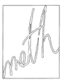
図6は、手書きで文字を記入したホワイトボードを、デジタルカメラで撮影することにより得た画像である。 FIG. 6 is an image obtained by photographing a whiteboard with handwritten characters with a digital camera.
本実施形態1に係る画像処理装置では、図6のような画像を入力画像として用いて、手書き文字領域のグラデーション検出とベクトル化記述が行われる。 In the image processing apparatus according to the first embodiment, gradation detection and vectorization description of a handwritten character area are performed using an image as shown in FIG. 6 as an input image.
本実施形態1から得られるグラデーション検出の結果が、図9に示されている。図9は、図6に示されている入力画像の領域Gに対応する部分の拡大図である。グラデーション検出の結果からは、手書き文字のストロークに強弱のある領域について、滑らかに画素値が変化する画像を取得することができる。図9では、ストロークに強弱のある部分は、強弱に沿って滑らかに画素値が変化しているものとする。 The gradation detection result obtained from the first embodiment is shown in FIG. FIG. 9 is an enlarged view of a portion corresponding to the region G of the input image shown in FIG. From the result of gradation detection, it is possible to acquire an image in which pixel values change smoothly in an area where the stroke of handwritten characters is strong or weak. In FIG. 9, it is assumed that the pixel value smoothly changes along the strength of the portion where the stroke is strong or weak.
以下で、図1の処理の内容を説明する。なお、図1に示されている処理は、本実施形態に係る画像処理装置のCPUによって実行される。 Hereinafter, the contents of the processing of FIG. 1 will be described. The process shown in FIG. 1 is executed by the CPU of the image processing apparatus according to the present embodiment.
まず、図1のステップS101で、画像の入力が行われる。 First, in step S101 in FIG. 1, an image is input.
次に、ステップS102で、色が類似する領域が、まとめて類似色領域として、取得される。類似色領域を取得する際は、近傍の画素(例えば、隣接する画素)と類似した色であれば、同一類似色領域としてまとめていくので、グラデーションがかかっている領域も1つの領域としてまとめられるものとする。図7は、ステップS102の処理の結果を示している。図7からわかるように、色が類似する領域をまとめることで、入力画像から手書き文字領域と背景領域を分離することができる。 Next, in step S102, areas having similar colors are collectively acquired as similar color areas. When acquiring similar color areas, if the colors are similar to neighboring pixels (for example, adjacent pixels), they are grouped together as the same similar color area, so that the area with gradation is also grouped as one area. Shall. FIG. 7 shows the result of the process of step S102. As can be seen from FIG. 7, the handwritten character area and the background area can be separated from the input image by grouping areas having similar colors.
次に、図1のステップS103で、ステップS102で得られた類似色領域から、その類似色領域の輪郭が、取得される。図8は、ステップS103の処理の結果を示している。図8に示されているように、ステップ103では、ステップS102で得られた類似色領域の輪郭が抽出される。
Next, in step S103 of FIG. 1, the outline of the similar color area is acquired from the similar color area obtained in step S102. FIG. 8 shows the result of the process of step S103. As shown in FIG. 8, in
次に、図1のステップS104で、ステップS103で得られた輪郭を用いて特徴点が設定される。ステップS104の処理の詳細については、図2を用いて後述する。 Next, in step S104 in FIG. 1, feature points are set using the contour obtained in step S103. Details of the processing in step S104 will be described later with reference to FIG.
次に、図1のステップS105で、ステップS104で設定された特徴点に対して、各特徴点の画素値が取得される。ステップS105の詳細については、図3を用いて後述する。 Next, in step S105 of FIG. 1, pixel values of the feature points are acquired for the feature points set in step S104. Details of step S105 will be described later with reference to FIG.
次に、図1のステップS106で、ステップS103で取得された輪郭と、ステップS105で取得された各特徴点の画素値とを用いて、ベクトルデータを生成する。 Next, in step S106 of FIG. 1, vector data is generated using the contour acquired in step S103 and the pixel value of each feature point acquired in step S105.
図2は、図1のステップS104の特徴点を設定する処理の詳細を示している。なお、図2に示されている処理は、本実施形態に係る画像処理装置のCPUによって実行される。 FIG. 2 shows details of the process for setting the feature points in step S104 of FIG. The process shown in FIG. 2 is executed by the CPU of the image processing apparatus according to the present embodiment.
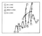
また、図10は、具体的な特徴点の設定例を示している。ここで、図10の特徴点の具体例を用いながら、図2の処理フローについて説明する。 FIG. 10 shows a specific feature point setting example. Here, the processing flow of FIG. 2 will be described using a specific example of the feature points of FIG.
まず、図2のステップS201で、輪郭の中心線が取得される。ここで、中心線とは輪郭に囲まれた領域を通る代表的な線のことである。本実施形態1では、中心線とは、細線化によって求められる線である。細線化処理は公知の技術を利用することが可能であり、輪郭に基づいて中心線とその線幅の情報を得ることができる。 First, in step S201 in FIG. 2, the center line of the contour is acquired. Here, the center line is a representative line passing through a region surrounded by an outline. In the first embodiment, the center line is a line obtained by thinning. For the thinning process, a known technique can be used, and information on the center line and its line width can be obtained based on the contour.
以下で説明する、ステップS202〜S205は、いずれも特徴点の設定に関するものであり、特徴点は全てステップS201によって得られる中心線上に設定される。 Steps S202 to S205 described below all relate to the setting of feature points, and all feature points are set on the center line obtained in step S201.
ステップS202で、ステップS201によって求まる中心線の端点が特徴点とされる。図10の例では、端点の個所として特徴点に設定される位置が四角の記号(□)で示されている。 In step S202, the end point of the center line obtained in step S201 is set as a feature point. In the example of FIG. 10, positions set as feature points as end points are indicated by square symbols (□).
次に、ステップS203で、中心線の曲率が高い箇所が特徴点とされる。 Next, in step S203, a point having a high curvature of the center line is set as a feature point.
図10では、曲率が高い箇所として特徴点に設定される領域が丸記号(〇)で示されている。 In FIG. 10, a region set as a feature point as a portion having a high curvature is indicated by a circle symbol (◯).
次に、ステップS204で、中心線が交差する箇所が特徴点とされる。 Next, in step S204, a point where the center lines intersect is determined as a feature point.
図10では、交差する箇所として特徴点に設定される領域がバツ記号(×)で示されている。 In FIG. 10, a region set as a feature point as a crossing point is indicated by a cross symbol (x).
次に、ステップS205で、中心線の画素値の変化が急に変わる個所に基づき特徴点が求められる。 Next, in step S205, a feature point is obtained based on the location where the change in the pixel value of the center line changes suddenly.
図10では、画素値の変化に基づき特徴点に設定された箇所が三角記号(△)で示されている。 In FIG. 10, locations set as feature points based on changes in pixel values are indicated by triangular symbols (Δ).
以下では、画素値の変化に基づく特徴点の設定手法についての一例を、図11を用いて説明する。 Hereinafter, an example of a feature point setting method based on a change in pixel value will be described with reference to FIG.
図11は、縦軸に明度、横軸に端点から中心線に沿った距離を示すグラフの例である。上記端点とは、中心線の端点のことであり、明度が急激に変化している箇所を特徴点として設定する。明度の急激な変化は、図11に示すグラフの二階微分を計算したときに、閾値以上となる個所、もしくはグラフが極値1100を持つ個所を検出することで求められる。
FIG. 11 is an example of a graph showing lightness on the vertical axis and distance along the center line from the end points on the horizontal axis. The end point is an end point of the center line, and a location where the brightness is rapidly changed is set as a feature point. A sharp change in brightness can be obtained by detecting a location where the second derivative of the graph shown in FIG. 11 is equal to or greater than a threshold value or a location where the graph has an
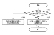
図3は、図1のステップS105の特徴点における画素値を取得する処理の詳細を示している。なお、図3に示されている処理は、本実施形態に係る画像処理装置のCPUによって実行される。 FIG. 3 shows details of the processing for acquiring pixel values at the feature points in step S105 of FIG. 3 is executed by the CPU of the image processing apparatus according to the present embodiment.
特徴点の画素値を取得する場合には、中心線が交差していない個所の特徴点の場合には、入力画像における対応する位置の画素値を取得する。中心線が交差している個所の特徴点の場合には、交差点の画素値は濃い色になることが多いため、入力画像における対応する位置の画素値をそのまま用いるのは望ましくない。そこで、本発明では、各中心線に沿って隣接する位置にある画素値を取得するものとする。 When acquiring the pixel value of the feature point, in the case of the feature point where the center line does not intersect, the pixel value of the corresponding position in the input image is acquired. In the case of feature points where the center lines intersect, the pixel value at the intersection often becomes a dark color, so it is not desirable to use the pixel value at the corresponding position in the input image as it is. Therefore, in the present invention, pixel values at adjacent positions along each center line are acquired.
まず、図3のステップS301で、特徴点が、ステップS204によって設定された中心線が交差する箇所の特徴点か、それ以外かが判定される。 First, in step S301 in FIG. 3, it is determined whether the feature point is a feature point where the center line set in step S204 intersects or not.
ステップS301で、特徴点が、ステップS204によって設定された中心線が交差する箇所の特徴点であると判定された場合には、ステップS303に処理が進む。 If it is determined in step S301 that the feature point is a feature point where the center line set in step S204 intersects, the process proceeds to step S303.
一方、ステップS301で、特徴点が、ステップS204によって設定された中心線が交差する箇所の特徴点でないと判定された場合には、ステップS302に処理が進む。 On the other hand, if it is determined in step S301 that the feature point is not a feature point where the center line set in step S204 intersects, the process proceeds to step S302.
ステップS302では、該特徴点の位置に対応する入力画像の画素値を取得し、当該特徴点の画素値とする。 In step S302, the pixel value of the input image corresponding to the position of the feature point is acquired and set as the pixel value of the feature point.
ステップS303で、特徴点を含む中心線上の画素値の変化が連続になるように特徴点の画素値が推測して求められる。例えば、2つの線が交差している場合、交差位置からは3〜4本の線が伸びていることになるので、それぞれの方向について画素値を求める。すなわち、中心線に沿って各方向に数画素隣の画素値を取得し、それぞれの方向についての画素値として得る。また、入力画像上において交差位置に対応する位置の画素値も取得しておく。よって、本実施形態では、交差位置に対応する入力画像上の画素値と、中心線が伸びている各方向における隣接する3つまたは4つの画素値とが得られるものとする。 In step S303, the pixel value of the feature point is estimated and obtained so that the change in the pixel value on the center line including the feature point is continuous. For example, when two lines intersect, three to four lines extend from the intersecting position, and pixel values are obtained for each direction. That is, pixel values adjacent to several pixels in each direction along the center line are acquired and obtained as pixel values for each direction. Further, the pixel value at the position corresponding to the intersection position on the input image is also acquired. Therefore, in this embodiment, it is assumed that the pixel value on the input image corresponding to the intersection position and three or four adjacent pixel values in each direction in which the center line extends are obtained.
図4は、図1中のステップS106の処理を、詳細に説明したものである。なお、図4に示されている処理は、本実施形態に係る画像処理装置のCPUによって実行される。 FIG. 4 explains in detail the processing in step S106 in FIG. Note that the processing shown in FIG. 4 is executed by the CPU of the image processing apparatus according to the present embodiment.
まず、図4のステップS401は、全ての中心線について処理が終わるまで、ステップS402〜S405までの処理を繰り返すためのループ端である。ステップS401では、未処理の中心線の1つを処理対象としてステップS402に進む。 First, step S401 in FIG. 4 is a loop end for repeating the processing of steps S402 to S405 until the processing is completed for all the center lines. In step S401, one of the unprocessed center lines is processed, and the process proceeds to step S402.
ステップS402は、全ての特徴点間について処理が終わるまで、ステップS403の処理を繰り返すためのループ端である。ステップS402では、未処理の特徴点間の1つを処理対象として、ステップS403に進む。なお、ここで、特徴点間とは、中心線で繋がっている2つの隣接する特徴点の間を示す。 Step S402 is a loop end for repeating the process of step S403 until the process between all feature points is completed. In step S402, one of the unprocessed feature points is set as a processing target, and the process proceeds to step S403. Here, between feature points means between two adjacent feature points connected by a center line.
ステップS403では、隣接する特徴点と特徴点の間を、グラデーションを用いたベクトル表現で記述する処理を行う。この処理の詳細は図5を用いて後述する。 In step S403, a process is described between adjacent feature points in a vector expression using gradation. Details of this processing will be described later with reference to FIG.
ステップS404は、ステップS402のループ端の終端である。 Step S404 is the end of the loop end of step S402.
ステップS405では、当該処理対象としている1つの中心線について、ステップS402〜S404の処理で得られた複数の特徴点間のベクトル表現を、当該1つの中心線を表すベクトル表現として列挙する。すなわち、特徴点間毎の複数のベクトル表現に分離しているので、これらを1つの中心線でつながったオブジェクトとして扱えるように、オブジェクト単位で、まとめる処理を行う。例えば、XML表記を行う場合、当該オブジェクトを表すタグを定義し、中心線ごと(すなわち、文字や単語などのオブジェクトごと)に、特徴点間ごとのベクトル表記をまとめて表記する。 In step S405, with respect to one center line to be processed, vector expressions between a plurality of feature points obtained by the processes in steps S402 to S404 are listed as vector expressions representing the one center line. That is, since it is separated into a plurality of vector representations for each feature point, a process of grouping them in units of objects is performed so that these can be handled as objects connected by one center line. For example, when performing XML notation, a tag representing the object is defined, and vector notation between feature points is collectively described for each center line (that is, for each object such as a character or a word).
ステップS406は、ステップS401のループ端の終端であり、全ての中心線についてS402〜S405の処理が終了すると、当該ループ処理を終了する。 Step S406 is the end of the loop end of step S401, and when the processing of S402 to S405 is finished for all the center lines, the loop processing is finished.
図5は、図4のステップS403における処理の詳細を示している。なお、図5に示されている処理は、本実施形態に係る画像処理装置のCPUによって実行される。 FIG. 5 shows details of the processing in step S403 of FIG. Note that the processing shown in FIG. 5 is executed by the CPU of the image processing apparatus according to the present embodiment.
まず、図5のステップS501では、図1のステップS103で得られた輪郭線について、ステップS403で処理対象としている2つの特徴点で分割することにより、当該2つの特徴点間の輪郭線を取得する。図12は、特徴点T1,T2の間の中心線と、当該2つの特徴点によって分割された輪郭線を示している。なお、輪郭線の分割処理は、例えば、特徴点から中心線と垂直な方向に延ばした直線を分割線として全体の輪郭線を分割していくことにより、特徴点間ごとの輪郭(分割線と輪郭線によって囲まれる領域の輪郭)を得ることができる。 First, in step S501 in FIG. 5, the contour line obtained in step S103 in FIG. 1 is divided by the two feature points to be processed in step S403, thereby obtaining a contour line between the two feature points. To do. FIG. 12 shows a center line between the feature points T1 and T2 and a contour line divided by the two feature points. The contour dividing process is performed by, for example, dividing the entire contour line by using a straight line extending from the feature point in a direction perpendicular to the center line as a dividing line, so that the contour between the feature points (dividing line and The contour of the region surrounded by the contour line) can be obtained.
ステップS502では、当該輪郭線内に複数のサンプリングポイントを設定する。例えば、本実施形態では、当該中心線上の特徴点(図12の白丸の点)をサンプリングポイントとするが、更に輪郭線上の点(例えば図12の黒丸で示した点)や、それらの中間点をサンプリングポイントとしてもよい。中間点は、例えば、2つの特徴点中点や輪郭線上の中間点など、複数設定することが可能であるが、多すぎると後述するグラデーションの近似に時間がかかるため、サンプリングポイントは2〜12個程度にするのが望ましい。 In step S502, a plurality of sampling points are set within the contour line. For example, in this embodiment, the feature point on the center line (white circle point in FIG. 12) is used as a sampling point. However, a point on the contour line (for example, a point indicated by a black circle in FIG. 12) or an intermediate point therebetween. May be used as a sampling point. It is possible to set a plurality of intermediate points, for example, the middle point between two feature points and the intermediate point on the contour line. However, if there are too many intermediate points, it takes time to approximate the gradation described later, so the sampling points are 2-12. It is desirable to have about one.
ステップS503では、各サンプリングポイントにおける画素値を取得する。ただし、交差による特徴点の画素値については、図3のS303で求めた当該特徴点間の方向における画素値を用いるものとする。 In step S503, the pixel value at each sampling point is acquired. However, as the pixel value of the feature point due to the intersection, the pixel value in the direction between the feature points obtained in S303 of FIG. 3 is used.
ステップS504では、各サンプリングポイントにおける画素値に基づいて、線形のグラデーションで近似を行う。すなわち、SVG記法を用いて表現する場合、linearGradientのタグを用いて、グラデーションの方向と属性を定義する。グラデーションの傾きと方向は、開始座標と終了座標を指定することで指定できる。更に、stopタグで使用する色をstop−color属性で表し、その色の位置をoffset属性で定義する。 In step S504, approximation is performed with a linear gradation based on the pixel value at each sampling point. That is, when expressing using the SVG notation, the direction and attribute of the gradation are defined using a linearGradient tag. The gradient slope and direction can be specified by specifying the start and end coordinates. Furthermore, the color used in the stop tag is represented by a stop-color attribute, and the position of the color is defined by the offset attribute.
ステップS505では、ステップS501で得た当該特徴点間の輪郭線をベクトル表現にする。本実施形態では、当該特徴点間の中心線と線幅で近似することによりベクトル表現に変換するものとするが、輪郭線そのものを近似するようにしても構わない。そして、そのベクトル表現の塗り潰し色として、ステップS504で定義したlinearGradientを指定する。 In step S505, the contour line between the feature points obtained in step S501 is expressed as a vector. In the present embodiment, the vector expression is converted by approximating the center line and the line width between the feature points. However, the outline itself may be approximated. Then, the linearGradient defined in step S504 is designated as the fill color of the vector expression.
このように図5の処理を行うことにより、特徴点間のグラデーションをベクトル表現にすることができる。また、このようにして作成された特徴点間のグラデーションのベクトル表現は、図4のステップS405で、オブジェクト毎にまとめられる。なお、交差による特徴点は複数のストロークが混合した色(例えば濃い色)になることが多いので、交差点の特徴点の画素値は入力画像から得た画素値で表現するのが好適である。 By performing the processing of FIG. 5 in this way, the gradation between the feature points can be expressed as a vector. Further, the gradation vector representation between the feature points created in this way is collected for each object in step S405 of FIG. Note that feature points due to intersection often have a color (for example, dark color) in which a plurality of strokes are mixed. Therefore, it is preferable that the pixel value of the feature point at the intersection is represented by a pixel value obtained from the input image.
上記で説明した処理により、入力画像から輪郭を取得し、その内部をグラデーション記述することができる。本実施形態では、一例として、ホワイトボード上の手書き文字をデジタルカメラで撮影した画像を入力画像としたが、これに限るものではなく、紙に記載された手書き文字や手書き図形をスキャナで読み取ることにより得た画像を入力画像としてもよい。また、本発明は、手書きに限るものではなく、グラデーションしている文字や図形に対して適用可能である。 By the processing described above, an outline can be acquired from the input image and the inside can be described with gradation. In the present embodiment, as an example, an image obtained by photographing a handwritten character on a whiteboard with a digital camera is used as an input image. However, the present invention is not limited to this. The image obtained by the above may be used as the input image. In addition, the present invention is not limited to handwriting, but can be applied to gradation characters and figures.
<その他の実施形態>
本発明は、さらに、複数の機器(例えばコンピュータ、インターフェース機器、リーダ、プリンタなど)から構成されるシステムに適用することも、一つの機器からなる装置(複合機、プリンタ、ファクシミリ装置など)に適用することも可能である。
<Other embodiments>
The present invention can also be applied to a system composed of a plurality of devices (for example, a computer, an interface device, a reader, a printer, etc.), or to a device composed of a single device (a multifunction device, a printer, a facsimile device, etc.) It is also possible to do.
また本発明の目的は、上述した実施形態で示したフローチャートの手順を実現するプログラムコードを記憶した記憶媒体から、システムあるいは装置のコンピュータ(またはCPUやMPU)が、そのプログラムコードを読出し実行することによっても達成される。この場合、記憶媒体から読み出されたプログラムコード自体が上述した実施形態の機能を実現することになる。そのため、このプログラムコード及びプログラムコードを記憶/記録したコンピュータ読み取り可能な記憶媒体も本発明の一つを構成することになる。 Another object of the present invention is that a computer (or CPU or MPU) of a system or apparatus reads and executes the program code from a storage medium that stores the program code that realizes the procedure of the flowchart shown in the above-described embodiment. Is also achieved. In this case, the program code itself read from the storage medium realizes the functions of the above-described embodiment. Therefore, the program code and a computer-readable storage medium storing / recording the program code also constitute one aspect of the present invention.
プログラムコードを供給するための記憶媒体としては、例えば、フロッピー(登録商標)ディスク、ハードディスク、光ディスク、光磁気ディスク、CD−ROM、CD−R、磁気テープ、不揮発性のメモリカード、ROMなどを用いることができる。 As a storage medium for supplying the program code, for example, a floppy (registered trademark) disk, hard disk, optical disk, magneto-optical disk, CD-ROM, CD-R, magnetic tape, nonvolatile memory card, ROM, or the like is used. be able to.
また、前述した実施形態の機能は、コンピュータが、読み出したプログラムを実行することによって実現される。また、このプログラムの実行とは、そのプログラムの指示に基づき、コンピュータ上で稼動しているOSなどが、実際の処理の一部または全部を行う場合も含まれる。 The functions of the above-described embodiments are realized by a computer executing a read program. The execution of the program includes a case where an OS or the like running on the computer performs part or all of the actual processing based on an instruction of the program.
さらに、前述した実施形態の機能は、コンピュータに挿入された機能拡張ボードやコンピュータに接続された機能拡張ユニットによっても実現することもできる。この場合、まず、記憶媒体から読み出されたプログラムが、コンピュータに挿入された機能拡張ボードやコンピュータに接続された機能拡張ユニットに備わるメモリに書き込まれる。その後、そのプログラムの指示に基づき、その機能拡張ボードや機能拡張ユニットに備わるCPUなどが実際の処理の一部または全部を行う。こうした機能拡張ボードや機能拡張ユニットによる処理によっても前述した実施形態の機能が実現される。 Furthermore, the functions of the above-described embodiments can also be realized by a function expansion board inserted into a computer or a function expansion unit connected to a computer. In this case, first, the program read from the storage medium is written in a memory provided in a function expansion board inserted into the computer or a function expansion unit connected to the computer. Thereafter, based on the instructions of the program, the CPU provided in the function expansion board or function expansion unit performs part or all of the actual processing. The functions of the above-described embodiment are also realized by processing by such a function expansion board or function expansion unit.
また、前述した実施形態のフローチャートの各ステップは、ソフトウェア(コンピュータ)を用いて実現するものに限るものではなく、ハードウェア(電子回路)を用いて実現してもよい。 In addition, each step of the flowchart of the above-described embodiment is not limited to that realized using software (computer), and may be realized using hardware (electronic circuit).
1100 極値 1100 extreme value
Claims (15)
前記輪郭線に基づいて、複数の特徴点を設定する、特徴点の設定手段と、
前記複数の特徴点に基づいて前記輪郭線を分割し、当該分割された各輪郭線内に設定した複数のサンプリングポイントそれぞれの、前記入力画像における画素値を取得する、画素値の取得手段と、
前記複数のサンプリングポイントそれぞれの前記取得した画素値に基づいて、前記分割された各輪郭線のグラデーションの方向と属性を定義し、前記分割された各輪郭線をベクトル表現に変換し、当該変換されたベクトル表現の塗り潰し色として前記定義されたグラデーションの方向と属性を用いることにより、前記グラデーションがかかっている文字のベクトル表現を生成する生成手段と、
を有することを特徴とする画像処理装置。 A contour acquisition unit that acquires a gradation character in the input image as a similar color region, and acquires a contour line of the acquired similar color region;
A feature point setting means for setting a plurality of feature points based on the contour line;
A pixel value acquisition unit that divides the contour line based on the plurality of feature points and acquires pixel values in the input image for each of a plurality of sampling points set in the divided contour lines;
Based on the acquired pixel value of each of the plurality of sampling points, a gradation direction and an attribute of each of the divided contour lines are defined, and each of the divided contour lines is converted into a vector representation, and the conversion is performed. a generation unit by a fill color of vector representations Ru using the direction and attributes of the defined gradient, generating a vector representation of the character gradation is took,
An image processing apparatus comprising:
特徴点の設定手段が、前記輪郭線に基づいて、複数の特徴点を設定する、特徴点の設定ステップと、
画素値の取得手段が、前記複数の特徴点に基づいて前記輪郭線を分割し、当該分割された各輪郭線内に設定した複数のサンプリングポイントそれぞれの、前記入力画像における画素値を取得する、画素値の取得ステップと、
生成手段が、前記複数のサンプリングポイントそれぞれの前記取得した画素値に基づいて、前記分割された各輪郭線のグラデーションの方向と属性を定義し、前記分割された各輪郭線をベクトル表現に変換し、当該変換されたベクトル表現の塗り潰し色として前記定義されたグラデーションの方向と属性を用いることにより、前記グラデーションがかかっている文字のベクトル表現を生成する生成ステップと、
を有することを特徴とする画像処理方法。 A contour acquisition unit that acquires a contoured character in the input image as a similar color region and acquires a contour line of the acquired similar color region;
A feature point setting unit that sets a plurality of feature points based on the contour line; and
A pixel value acquisition unit divides the contour line based on the plurality of feature points, and acquires a pixel value in the input image for each of a plurality of sampling points set in each of the divided contour lines. A pixel value acquisition step;
The generation unit defines a gradation direction and an attribute of each of the divided contour lines based on the acquired pixel values of each of the plurality of sampling points, and converts each of the divided contour lines into a vector representation. a generation step of generating the by Ru with direction and attributes defined gradient vector representation of the character in which the gradation is taking a fill color of the transformed vector representations,
An image processing method comprising:
Priority Applications (2)
| Application Number | Priority Date | Filing Date | Title |
|---|---|---|---|
| JP2008187111A JP5067882B2 (en) | 2008-07-18 | 2008-07-18 | Image processing apparatus, image processing method, and program |
| US12/499,954 US8254693B2 (en) | 2008-07-18 | 2009-07-09 | Image processing apparatus, image processing method and program |
Applications Claiming Priority (1)
| Application Number | Priority Date | Filing Date | Title |
|---|---|---|---|
| JP2008187111A JP5067882B2 (en) | 2008-07-18 | 2008-07-18 | Image processing apparatus, image processing method, and program |
Publications (3)
| Publication Number | Publication Date |
|---|---|
| JP2010028429A JP2010028429A (en) | 2010-02-04 |
| JP2010028429A5 JP2010028429A5 (en) | 2011-09-01 |
| JP5067882B2 true JP5067882B2 (en) | 2012-11-07 |
Family
ID=41530348
Family Applications (1)
| Application Number | Title | Priority Date | Filing Date |
|---|---|---|---|
| JP2008187111A Expired - Fee Related JP5067882B2 (en) | 2008-07-18 | 2008-07-18 | Image processing apparatus, image processing method, and program |
Country Status (2)
| Country | Link |
|---|---|
| US (1) | US8254693B2 (en) |
| JP (1) | JP5067882B2 (en) |
Families Citing this family (5)
| Publication number | Priority date | Publication date | Assignee | Title |
|---|---|---|---|---|
| JP5335581B2 (en) * | 2009-07-01 | 2013-11-06 | キヤノン株式会社 | Image processing apparatus, image processing method, and program |
| JP5968098B2 (en) | 2012-06-14 | 2016-08-10 | キヤノン株式会社 | Image processing apparatus, image processing method, program, and storage medium |
| JP2015087167A (en) * | 2013-10-29 | 2015-05-07 | キヤノン株式会社 | Image processing method and image processing system |
| US11800056B2 (en) | 2021-02-11 | 2023-10-24 | Logitech Europe S.A. | Smart webcam system |
| US11800048B2 (en) | 2021-02-24 | 2023-10-24 | Logitech Europe S.A. | Image generating system with background replacement or modification capabilities |
Family Cites Families (21)
| Publication number | Priority date | Publication date | Assignee | Title |
|---|---|---|---|---|
| US5101448A (en) * | 1988-08-24 | 1992-03-31 | Hitachi, Ltd. | Method and apparatus for processing a document by utilizing an image |
| JPH04141783A (en) * | 1990-10-03 | 1992-05-15 | Dainippon Printing Co Ltd | Device and method for preparing electron beam graphic data |
| JPH05181966A (en) * | 1991-12-27 | 1993-07-23 | Minolta Camera Co Ltd | Image output method |
| JPH0787302A (en) * | 1993-09-16 | 1995-03-31 | Fuji Xerox Co Ltd | Document processor |
| JPH07121698A (en) * | 1993-10-26 | 1995-05-12 | Glory Ltd | Curve approximation method for handwritten data |
| US5621819A (en) * | 1994-04-22 | 1997-04-15 | Victor Company Of Japan, Ltd. | Multidimensional multi-valued color image compression and decompression method |
| DE69635101T2 (en) * | 1995-11-01 | 2006-06-01 | Canon K.K. | Method for extracting objects and image recording apparatus using this method |
| JPH1055447A (en) * | 1996-05-21 | 1998-02-24 | Monorisu:Kk | Object recognizing method and device using the same |
| JPH1125282A (en) * | 1997-06-30 | 1999-01-29 | Fuji Xerox Co Ltd | Picture forming device and method for generating gradation pattern |
| JPH11272860A (en) * | 1998-03-26 | 1999-10-08 | Meidensha Corp | Special line display method of drawings automatic input device |
| JP2000293696A (en) * | 1999-04-07 | 2000-10-20 | Matsushita Electric Ind Co Ltd | Picture recognizing device |
| US6901171B1 (en) * | 1999-04-30 | 2005-05-31 | Cognex Technology And Investment Corporation | Methods and apparatuses for refining groupings of edge points that represent a contour in an image |
| JP4612760B2 (en) * | 2000-04-25 | 2011-01-12 | キヤノン株式会社 | Image processing apparatus and method |
| JP4003465B2 (en) * | 2002-01-28 | 2007-11-07 | 松下電工株式会社 | Specific pattern recognition method, specific pattern recognition program, specific pattern recognition program recording medium, and specific pattern recognition apparatus |
| JP3964219B2 (en) * | 2002-01-29 | 2007-08-22 | シャープ株式会社 | Image processing apparatus, image processing method, image processing program, and recording medium |
| US7623712B2 (en) | 2005-06-09 | 2009-11-24 | Canon Kabushiki Kaisha | Image processing method and apparatus |
| JP2007066070A (en) * | 2005-08-31 | 2007-03-15 | Sharp Corp | Image information processor, and image information processing method and program |
| JP4748789B2 (en) * | 2005-12-05 | 2011-08-17 | キヤノン株式会社 | Image processing method and image processing apparatus |
| US7831107B2 (en) | 2005-10-17 | 2010-11-09 | Canon Kabushiki Kaisha | Image processing apparatus, image processing method, and program |
| JP2007183711A (en) * | 2006-01-04 | 2007-07-19 | Hitachi Software Eng Co Ltd | Program for image recognition by mahalanobis distance using diagonal graph |
| JP4799246B2 (en) * | 2006-03-30 | 2011-10-26 | キヤノン株式会社 | Image processing method and image processing apparatus |
-
2008
- 2008-07-18 JP JP2008187111A patent/JP5067882B2/en not_active Expired - Fee Related
-
2009
- 2009-07-09 US US12/499,954 patent/US8254693B2/en not_active Expired - Fee Related
Also Published As
| Publication number | Publication date |
|---|---|
| US20100014752A1 (en) | 2010-01-21 |
| JP2010028429A (en) | 2010-02-04 |
| US8254693B2 (en) | 2012-08-28 |
Similar Documents
| Publication | Publication Date | Title |
|---|---|---|
| EP3065063B1 (en) | Method for emphasizing differences in graphical appearance between an original document and a modified document with annotations | |
| US9632678B2 (en) | Image processing apparatus, image processing method, and program | |
| JP4738469B2 (en) | Image processing apparatus, image processing program, and image processing method | |
| US8787677B2 (en) | Image processing method, image processing apparatus, and program | |
| CN109146991B (en) | Picture format conversion method, device, equipment and storage medium | |
| JP5067882B2 (en) | Image processing apparatus, image processing method, and program | |
| JP2009093638A (en) | Image detection device and image detection method | |
| JP4748234B2 (en) | Image processing apparatus and image forming apparatus | |
| US20230162413A1 (en) | Stroke-Guided Sketch Vectorization | |
| US8150185B2 (en) | Image processing for generating a thin line binary image and extracting vectors | |
| US20110187721A1 (en) | Line drawing processing apparatus, storage medium storing a computer-readable program, and line drawing processing method | |
| JP4873554B2 (en) | Image distribution apparatus and image distribution method | |
| JP2010011450A (en) | Image-forming device and image processing method | |
| JP6546385B2 (en) | IMAGE PROCESSING APPARATUS, CONTROL METHOD THEREOF, AND PROGRAM | |
| JP2015158737A (en) | Image processor and image processing method | |
| US20090274394A1 (en) | Image processing method, image processing apparatus, and computer readable storage medium | |
| JP4825888B2 (en) | Document image processing apparatus and document image processing method | |
| JP2006237858A (en) | Image processing apparatus, image processing method, program for allowing computer to execute the method, and recording medium | |
| JP4259949B2 (en) | Image creating apparatus, image creating program, and recording medium | |
| JP2007109177A (en) | Image processing apparatus, its control method, and program | |
| US11017505B2 (en) | System and method for applying antialiasing to images | |
| US9031324B2 (en) | Image-processing device specifying encircling line for identifying sub-region of image | |
| US20170228902A1 (en) | Information processing apparatus and information processing method | |
| JP4435141B2 (en) | Character recognition device, character recognition method, and character recognition program | |
| JP4753889B2 (en) | Line extraction processing apparatus, line extraction processing program, recording medium storing line extraction processing program, and line extraction processing method |
Legal Events
| Date | Code | Title | Description |
|---|---|---|---|
| RD02 | Notification of acceptance of power of attorney |
Free format text: JAPANESE INTERMEDIATE CODE: A7422 Effective date: 20101106 |
|
| A521 | Request for written amendment filed |
Free format text: JAPANESE INTERMEDIATE CODE: A523 Effective date: 20110715 |
|
| A621 | Written request for application examination |
Free format text: JAPANESE INTERMEDIATE CODE: A621 Effective date: 20110715 |
|
| A977 | Report on retrieval |
Free format text: JAPANESE INTERMEDIATE CODE: A971007 Effective date: 20120419 |
|
| A131 | Notification of reasons for refusal |
Free format text: JAPANESE INTERMEDIATE CODE: A131 Effective date: 20120427 |
|
| A521 | Request for written amendment filed |
Free format text: JAPANESE INTERMEDIATE CODE: A523 Effective date: 20120626 |
|
| TRDD | Decision of grant or rejection written | ||
| A01 | Written decision to grant a patent or to grant a registration (utility model) |
Free format text: JAPANESE INTERMEDIATE CODE: A01 Effective date: 20120717 |
|
| A01 | Written decision to grant a patent or to grant a registration (utility model) |
Free format text: JAPANESE INTERMEDIATE CODE: A01 |
|
| A61 | First payment of annual fees (during grant procedure) |
Free format text: JAPANESE INTERMEDIATE CODE: A61 Effective date: 20120809 |
|
| FPAY | Renewal fee payment (event date is renewal date of database) |
Free format text: PAYMENT UNTIL: 20150824 Year of fee payment: 3 |
|
| R151 | Written notification of patent or utility model registration |
Ref document number: 5067882 Country of ref document: JP Free format text: JAPANESE INTERMEDIATE CODE: R151 |
|
| FPAY | Renewal fee payment (event date is renewal date of database) |
Free format text: PAYMENT UNTIL: 20150824 Year of fee payment: 3 |
|
| LAPS | Cancellation because of no payment of annual fees |