JP5067522B2 - Secondary battery electrolyte and secondary battery - Google Patents
Secondary battery electrolyte and secondary battery Download PDFInfo
- Publication number
- JP5067522B2 JP5067522B2 JP2006037698A JP2006037698A JP5067522B2 JP 5067522 B2 JP5067522 B2 JP 5067522B2 JP 2006037698 A JP2006037698 A JP 2006037698A JP 2006037698 A JP2006037698 A JP 2006037698A JP 5067522 B2 JP5067522 B2 JP 5067522B2
- Authority
- JP
- Japan
- Prior art keywords
- lithium
- negative electrode
- secondary battery
- electrolyte
- positive electrode
- Prior art date
- Legal status (The legal status is an assumption and is not a legal conclusion. Google has not performed a legal analysis and makes no representation as to the accuracy of the status listed.)
- Expired - Fee Related
Links
Images


Classifications
-
- H—ELECTRICITY
- H01—ELECTRIC ELEMENTS
- H01M—PROCESSES OR MEANS, e.g. BATTERIES, FOR THE DIRECT CONVERSION OF CHEMICAL ENERGY INTO ELECTRICAL ENERGY
- H01M10/00—Secondary cells; Manufacture thereof
- H01M10/05—Accumulators with non-aqueous electrolyte
- H01M10/056—Accumulators with non-aqueous electrolyte characterised by the materials used as electrolytes, e.g. mixed inorganic/organic electrolytes
- H01M10/0564—Accumulators with non-aqueous electrolyte characterised by the materials used as electrolytes, e.g. mixed inorganic/organic electrolytes the electrolyte being constituted of organic materials only
- H01M10/0566—Liquid materials
- H01M10/0568—Liquid materials characterised by the solutes
-
- H—ELECTRICITY
- H01—ELECTRIC ELEMENTS
- H01M—PROCESSES OR MEANS, e.g. BATTERIES, FOR THE DIRECT CONVERSION OF CHEMICAL ENERGY INTO ELECTRICAL ENERGY
- H01M10/00—Secondary cells; Manufacture thereof
- H01M10/05—Accumulators with non-aqueous electrolyte
-
- H—ELECTRICITY
- H01—ELECTRIC ELEMENTS
- H01M—PROCESSES OR MEANS, e.g. BATTERIES, FOR THE DIRECT CONVERSION OF CHEMICAL ENERGY INTO ELECTRICAL ENERGY
- H01M10/00—Secondary cells; Manufacture thereof
- H01M10/05—Accumulators with non-aqueous electrolyte
- H01M10/052—Li-accumulators
-
- H—ELECTRICITY
- H01—ELECTRIC ELEMENTS
- H01M—PROCESSES OR MEANS, e.g. BATTERIES, FOR THE DIRECT CONVERSION OF CHEMICAL ENERGY INTO ELECTRICAL ENERGY
- H01M10/00—Secondary cells; Manufacture thereof
- H01M10/05—Accumulators with non-aqueous electrolyte
- H01M10/056—Accumulators with non-aqueous electrolyte characterised by the materials used as electrolytes, e.g. mixed inorganic/organic electrolytes
- H01M10/0564—Accumulators with non-aqueous electrolyte characterised by the materials used as electrolytes, e.g. mixed inorganic/organic electrolytes the electrolyte being constituted of organic materials only
- H01M10/0566—Liquid materials
- H01M10/0569—Liquid materials characterised by the solvents
-
- H—ELECTRICITY
- H01—ELECTRIC ELEMENTS
- H01M—PROCESSES OR MEANS, e.g. BATTERIES, FOR THE DIRECT CONVERSION OF CHEMICAL ENERGY INTO ELECTRICAL ENERGY
- H01M10/00—Secondary cells; Manufacture thereof
- H01M10/05—Accumulators with non-aqueous electrolyte
- H01M10/058—Construction or manufacture
- H01M10/0587—Construction or manufacture of accumulators having only wound construction elements, i.e. wound positive electrodes, wound negative electrodes and wound separators
-
- H—ELECTRICITY
- H01—ELECTRIC ELEMENTS
- H01M—PROCESSES OR MEANS, e.g. BATTERIES, FOR THE DIRECT CONVERSION OF CHEMICAL ENERGY INTO ELECTRICAL ENERGY
- H01M10/00—Secondary cells; Manufacture thereof
- H01M10/42—Methods or arrangements for servicing or maintenance of secondary cells or secondary half-cells
- H01M10/4235—Safety or regulating additives or arrangements in electrodes, separators or electrolyte
-
- H—ELECTRICITY
- H01—ELECTRIC ELEMENTS
- H01M—PROCESSES OR MEANS, e.g. BATTERIES, FOR THE DIRECT CONVERSION OF CHEMICAL ENERGY INTO ELECTRICAL ENERGY
- H01M4/00—Electrodes
- H01M4/02—Electrodes composed of, or comprising, active material
- H01M4/36—Selection of substances as active materials, active masses, active liquids
- H01M4/38—Selection of substances as active materials, active masses, active liquids of elements or alloys
- H01M4/386—Silicon or alloys based on silicon
-
- H—ELECTRICITY
- H01—ELECTRIC ELEMENTS
- H01M—PROCESSES OR MEANS, e.g. BATTERIES, FOR THE DIRECT CONVERSION OF CHEMICAL ENERGY INTO ELECTRICAL ENERGY
- H01M4/00—Electrodes
- H01M4/02—Electrodes composed of, or comprising, active material
- H01M4/36—Selection of substances as active materials, active masses, active liquids
- H01M4/38—Selection of substances as active materials, active masses, active liquids of elements or alloys
- H01M4/387—Tin or alloys based on tin
-
- H—ELECTRICITY
- H01—ELECTRIC ELEMENTS
- H01M—PROCESSES OR MEANS, e.g. BATTERIES, FOR THE DIRECT CONVERSION OF CHEMICAL ENERGY INTO ELECTRICAL ENERGY
- H01M2300/00—Electrolytes
- H01M2300/0017—Non-aqueous electrolytes
- H01M2300/0025—Organic electrolyte
- H01M2300/0028—Organic electrolyte characterised by the solvent
- H01M2300/0037—Mixture of solvents
- H01M2300/004—Three solvents
-
- H—ELECTRICITY
- H01—ELECTRIC ELEMENTS
- H01M—PROCESSES OR MEANS, e.g. BATTERIES, FOR THE DIRECT CONVERSION OF CHEMICAL ENERGY INTO ELECTRICAL ENERGY
- H01M4/00—Electrodes
- H01M4/02—Electrodes composed of, or comprising, active material
- H01M4/36—Selection of substances as active materials, active masses, active liquids
- H01M4/48—Selection of substances as active materials, active masses, active liquids of inorganic oxides or hydroxides
- H01M4/50—Selection of substances as active materials, active masses, active liquids of inorganic oxides or hydroxides of manganese
- H01M4/505—Selection of substances as active materials, active masses, active liquids of inorganic oxides or hydroxides of manganese of mixed oxides or hydroxides containing manganese for inserting or intercalating light metals, e.g. LiMn2O4 or LiMn2OxFy
-
- H—ELECTRICITY
- H01—ELECTRIC ELEMENTS
- H01M—PROCESSES OR MEANS, e.g. BATTERIES, FOR THE DIRECT CONVERSION OF CHEMICAL ENERGY INTO ELECTRICAL ENERGY
- H01M4/00—Electrodes
- H01M4/02—Electrodes composed of, or comprising, active material
- H01M4/36—Selection of substances as active materials, active masses, active liquids
- H01M4/48—Selection of substances as active materials, active masses, active liquids of inorganic oxides or hydroxides
- H01M4/52—Selection of substances as active materials, active masses, active liquids of inorganic oxides or hydroxides of nickel, cobalt or iron
- H01M4/525—Selection of substances as active materials, active masses, active liquids of inorganic oxides or hydroxides of nickel, cobalt or iron of mixed oxides or hydroxides containing iron, cobalt or nickel for inserting or intercalating light metals, e.g. LiNiO2, LiCoO2 or LiCoOxFy
-
- Y—GENERAL TAGGING OF NEW TECHNOLOGICAL DEVELOPMENTS; GENERAL TAGGING OF CROSS-SECTIONAL TECHNOLOGIES SPANNING OVER SEVERAL SECTIONS OF THE IPC; TECHNICAL SUBJECTS COVERED BY FORMER USPC CROSS-REFERENCE ART COLLECTIONS [XRACs] AND DIGESTS
- Y02—TECHNOLOGIES OR APPLICATIONS FOR MITIGATION OR ADAPTATION AGAINST CLIMATE CHANGE
- Y02E—REDUCTION OF GREENHOUSE GAS [GHG] EMISSIONS, RELATED TO ENERGY GENERATION, TRANSMISSION OR DISTRIBUTION
- Y02E60/00—Enabling technologies; Technologies with a potential or indirect contribution to GHG emissions mitigation
- Y02E60/10—Energy storage using batteries
-
- Y—GENERAL TAGGING OF NEW TECHNOLOGICAL DEVELOPMENTS; GENERAL TAGGING OF CROSS-SECTIONAL TECHNOLOGIES SPANNING OVER SEVERAL SECTIONS OF THE IPC; TECHNICAL SUBJECTS COVERED BY FORMER USPC CROSS-REFERENCE ART COLLECTIONS [XRACs] AND DIGESTS
- Y02—TECHNOLOGIES OR APPLICATIONS FOR MITIGATION OR ADAPTATION AGAINST CLIMATE CHANGE
- Y02P—CLIMATE CHANGE MITIGATION TECHNOLOGIES IN THE PRODUCTION OR PROCESSING OF GOODS
- Y02P70/00—Climate change mitigation technologies in the production process for final industrial or consumer products
- Y02P70/50—Manufacturing or production processes characterised by the final manufactured product
Description
本発明は、電解質塩を含む二次電池用電解液およびそれを用いた二次電池に関する。 The present invention relates to an electrolytic solution for a secondary battery containing an electrolyte salt and a secondary battery using the same.
近年、カメラ一体型VTR(ビデオテープレコーダ),デジタルスチルカメラ,携帯電話,携帯情報端末あるいはノート型コンピュータ等のポータブル電子機器が多く登場し、その小型軽量化が図られている。それに伴い、電子機器のポータブル電源として、電池、特に二次電池について、エネルギー密度を向上させるための研究開発が活発に進められている。中でも、負極に炭素材料を用い、正極にリチウム(Li)と遷移金属との複合材料を用い、電解液に炭酸エステルを用いたリチウムイオン二次電池は、従来の鉛電池およびニッケルカドミウム電池と比較して大きなエネルギー密度が得られるため広く実用化されている。 In recent years, many portable electronic devices such as a camera-integrated VTR (video tape recorder), a digital still camera, a mobile phone, a portable information terminal, or a notebook computer have appeared, and their size and weight have been reduced. Accordingly, as a portable power source for electronic devices, research and development for improving the energy density of batteries, particularly secondary batteries, are being actively promoted. Among these, lithium ion secondary batteries using a carbon material for the negative electrode, a composite material of lithium (Li) and a transition metal for the positive electrode, and a carbonate ester for the electrolyte are compared with conventional lead batteries and nickel cadmium batteries. Since a large energy density can be obtained, it is widely used.
また最近では、携帯用電子機器の高性能化に伴い、更なる容量の向上が求められており、負極活物質として炭素材料に代えてスズ(Sn)あるいはケイ素(Si)などを用いることが検討されている。スズの理論容量は994mAh/g、ケイ素の理論容量は4199mAh/gと、黒鉛の理論容量の372mAh/gに比べて格段に大きく、容量の向上を期待できるからである。特に、スズあるいはケイ素の薄膜を集電体上に形成した負極は、リチウムの吸蔵および放出によっても、負極活物質が微粉化することなく、比較的大きな放電容量を保持できることが報告されている(例えば、特許文献1参照)。 Recently, with the improvement in performance of portable electronic devices, further improvement in capacity has been demanded, and it is considered to use tin (Sn) or silicon (Si) instead of carbon material as the negative electrode active material. Has been. This is because the theoretical capacity of tin is 994 mAh / g and the theoretical capacity of silicon is 4199 mAh / g, which is much larger than the theoretical capacity of graphite, 372 mAh / g, and an improvement in capacity can be expected. In particular, it has been reported that a negative electrode in which a thin film of tin or silicon is formed on a current collector can maintain a relatively large discharge capacity without pulverization of the negative electrode active material even by insertion and extraction of lithium ( For example, see Patent Document 1).
また、高エネルギー密度を得ることができる二次電池としては、負極にリチウム金属を用い、負極反応にリチウム金属の析出および溶解反応のみを利用したリチウム金属二次電池がある。リチウム金属二次電池は、リチウム金属の理論電気化学当量が2054mAh/cm3 と大きく、黒鉛の2.5倍にも相当するので、容量の向上が期待されている。これまでも、多くの研究者等により実用化の研究開発がなされている(例えば、非特許文献1参照)。 As a secondary battery capable of obtaining a high energy density, there is a lithium metal secondary battery that uses lithium metal for the negative electrode and uses only precipitation and dissolution reactions of lithium metal for the negative electrode reaction. The lithium metal secondary battery has a theoretical electrochemical equivalent of lithium metal as large as 2054 mAh / cm 3 , which corresponds to 2.5 times that of graphite, and is expected to improve capacity. Until now, research and development for practical use has been made by many researchers and the like (for example, see Non-Patent Document 1).
更に最近では、負極の容量がリチウムの吸蔵および放出による容量成分と、リチウムの析出および溶解による容量成分とを含み、かつその和により表される二次電池が開発されている(例えば、特許文献2参照。)。これは、負極にリチウムを吸蔵および放出することが可能な炭素材料を用い、充電の途中においてその炭素材料の表面にリチウムを析出させるようにしたものである。この二次電池によれば、リチウム金属二次電池と同様に高エネルギー密度を達成させることが期待できる。
しかしながら、このように負極にスズ,ケイ素あるいはリチウム金属を用いた電池では、従来の負極に炭素材料を用いた電池に比べて活性が高いので、電解液に従来より用いられている炭酸エステルあるいは六フッ化リン酸リチウムなどを用いると、これらが分解されてしまい、しかもリチウムが不活性化されてしまうなどの問題があった。よって、充放電を繰り返すと充放電効率が低下してしまい、十分なサイクル特性を得ることができなかった。 However, since the battery using tin, silicon, or lithium metal for the negative electrode is more active than the battery using the carbon material for the conventional negative electrode, the carbonate or hexavalent carbonate conventionally used for the electrolyte is used. When lithium fluorophosphate or the like is used, there is a problem that they are decomposed and lithium is inactivated. Therefore, if charging / discharging is repeated, charging / discharging efficiency will fall and sufficient cycle characteristics could not be obtained.
ところで、負極活物質として炭素材料を用いた場合でも、電池電圧を高くすることで放電容量が向上することが知られているが、この場合にも、電解液が分解されやすくなるので、充放電効率が低下してしまい、サイクル特性が低下してしまうという問題があった。 By the way, even when a carbon material is used as the negative electrode active material, it is known that the discharge capacity is improved by increasing the battery voltage. However, in this case as well, the electrolytic solution is easily decomposed. There is a problem that efficiency is lowered and cycle characteristics are lowered.
本発明はかかる問題点に鑑みてなされたもので、その目的は、サイクル特性を向上させることができる二次電池用電解液、およびそれを用いた二次電池を提供することにある。 The present invention has been made in view of such problems, and an object thereof is to provide an electrolytic solution for a secondary battery capable of improving cycle characteristics, and a secondary battery using the same.
本発明による二次電池用電解液は、1,1,2,2,3,3−ヘキサフルオロプロパン−1,3−ジスルホンイミドリチウム、2,2,3,3,4,4−ヘキサフルオログルタルイミドリチウム、オルト−スルホベンズイミドリチウム、1,1,2,2,3,3−ヘキサフルオロプロパン−1,3−ジスルホンイミドナトリウム、2,2,3,3,4,4−ヘキサフルオログルタルイミドナトリウム、オルト−スルホベンズイミドナトリウム、1,1,2,2,3,3−ヘキサフルオロプロパン−1,3−ジスルホンイミドカリウム、2,2,3,3,4,4−ヘキサフルオログルタルイミドカリウム、オルト−スルホベンズイミドカリウム、1,1,2,2−テトラフルオロエタン−1,3−ジスルホンイミドリチウム、1−トリフルオロメチル−1,2,2,3,3−ペンタフルオロプロパン−1,3−ジスルホンイミドリチウムおよび1,1,2,2,3,3,4,4−オクタフルオロブチル−1,3−ジスルホンイミドリチウムのうちの少なくとも1種の環状のイミド塩を含有する電解質塩と、ハロゲン原子を有する環状の炭酸エステル誘導体を含有する非水溶媒とを含むものである。 The electrolyte for a secondary battery according to the present invention includes 1,1,2,2,3,3-hexafluoropropane-1,3-disulfonimidolithium , 2,2,3,3,4,4-hexafluoroglutar. Imidolithium, ortho-sulfobenzimidolithium, 1,1,2,2,3,3-hexafluoropropane-1,3-disulfonimide sodium, 2,2,3,3,4,4-hexafluoroglutarimide Sodium, sodium ortho-sulfobenzimide, 1,1,2,2,3,3-hexafluoropropane-1,3-disulfonimide potassium, 2,2,3,3,4,4-hexafluoroglutarimide potassium Ortho-sulfobenzimide potassium, 1,1,2,2-tetrafluoroethane-1,3-disulfonimide lithium, 1-trifluoro Methyl-1,2,2,3,3-pentafluoropropane-1,3-disulfonimide lithium and 1,1,2,2,3,3,4,4-octafluorobutyl-1,3-disulfonimide An electrolyte salt containing at least one cyclic imide salt of lithium and a non-aqueous solvent containing a cyclic carbonate derivative having a halogen atom are included.
本発明による第1の二次電池は、正極および負極と共に非水溶媒および電解質塩を含む電解液を備え、負極は、電極反応物質を吸蔵および放出することが可能であり、構成元素としてスズ(Sn)およびケイ素(Si)のうちの少なくとも一方を含む負極材料を含有し、電解液は、1,1,2,2,3,3−ヘキサフルオロプロパン−1,3−ジスルホンイミドリチウム、2,2,3,3,4,4−ヘキサフルオログルタルイミドリチウム、オルト−スルホベンズイミドリチウム、1,1,2,2,3,3−ヘキサフルオロプロパン−1,3−ジスルホンイミドナトリウム、2,2,3,3,4,4−ヘキサフルオログルタルイミドナトリウム、オルト−スルホベンズイミドナトリウム、1,1,2,2,3,3−ヘキサフルオロプロパン−1,3−ジスルホンイミドカリウム、2,2,3,3,4,4−ヘキサフルオログルタルイミドカリウム、オルト−スルホベンズイミドカリウム、1,1,2,2−テトラフルオロエタン−1,3−ジスルホンイミドリチウム、1−トリフルオロメチル−1,2,2,3,3−ペンタフルオロプロパン−1,3−ジスルホンイミドリチウムおよび1,1,2,2,3,3,4,4−オクタフルオロブチル−1,3−ジスルホンイミドリチウムのうちの少なくとも1種の環状のイミド塩と、ハロゲン原子を有する環状の炭酸エステル誘導体とを含むものである。 A first secondary battery according to the present invention includes an electrolyte containing a nonaqueous solvent and an electrolyte salt together with a positive electrode and a negative electrode. The negative electrode can absorb and release an electrode reactant, and tin ( A negative electrode material containing at least one of Sn) and silicon (Si) , and the electrolyte includes 1,1,2,2,3,3-hexafluoropropane-1,3-disulfonimidolithium, 2, 2,3,3,4,4-hexafluoroglutarimide lithium, ortho-sulfobenzimide lithium, 1,1,2,2,3,3-hexafluoropropane-1,3-disulfonimide sodium, 2,2 , 3,3,4,4-hexafluoroglutarimide sodium, ortho-sulfobenzimide sodium, 1,1,2,2,3,3-hexafluoropropane- 1,3-disulfonimide potassium, 2,2,3,3,4,4-hexafluoroglutarimide potassium, ortho-sulfobenzimide potassium, 1,1,2,2-tetrafluoroethane-1,3-disulfone Imidolithium, 1-trifluoromethyl-1,2,2,3,3-pentafluoropropane-1,3-disulfonimidolithium and 1,1,2,2,3,3,4,4-octafluorobutyl It contains at least one cyclic imide salt of -1,3-disulfonimidolithium and a cyclic carbonate derivative having a halogen atom .
本発明による第2の二次電池は、正極および負極と共に非水溶媒および電解質塩を含む電解液を備え、一対の正極および負極当たりの完全充電状態における開回路電圧が4.25V以上であり、電解液は、1,1,2,2,3,3−ヘキサフルオロプロパン−1,3−ジスルホンイミドリチウム、2,2,3,3,4,4−ヘキサフルオログルタルイミドリチウム、オルト−スルホベンズイミドリチウム、1,1,2,2,3,3−ヘキサフルオロプロパン−1,3−ジスルホンイミドナトリウム、2,2,3,3,4,4−ヘキサフルオログルタルイミドナトリウム、オルト−スルホベンズイミドナトリウム、1,1,2,2,3,3−ヘキサフルオロプロパン−1,3−ジスルホンイミドカリウム、2,2,3,3,4,4−ヘキサフルオログルタルイミドカリウム、オルト−スルホベンズイミドカリウム、1,1,2,2−テトラフルオロエタン−1,3−ジスルホンイミドリチウム、1−トリフルオロメチル−1,2,2,3,3−ペンタフルオロプロパン−1,3−ジスルホンイミドリチウムおよび1,1,2,2,3,3,4,4−オクタフルオロブチル−1,3−ジスルホンイミドリチウムのうちの少なくとも1種の環状のイミド塩と、ハロゲン原子を有する環状の炭酸エステル誘導体とを含むものである。 A second secondary battery according to the present invention includes an electrolyte containing a nonaqueous solvent and an electrolyte salt together with a positive electrode and a negative electrode, and an open circuit voltage in a fully charged state per pair of the positive electrode and the negative electrode is 4.25 V or more, The electrolytes are 1,1,2,2,3,3-hexafluoropropane-1,3-disulfonimide lithium , 2,2,3,3,4,4-hexafluoroglutarimide lithium, ortho-sulfobenz Imidolithium, 1,1,2,2,3,3-hexafluoropropane-1,3-disulfonimide sodium, 2,2,3,3,4,4-hexafluoroglutarimide sodium, ortho-sulfobenzimide Sodium, 1,1,2,2,3,3-hexafluoropropane-1,3-disulfonimide potassium, 2,2,3,3,4,4-hexaflu Potassium orthorimide, potassium ortho-sulfobenzimide, lithium 1,1,2,2-tetrafluoroethane-1,3-disulfonimide, 1-trifluoromethyl-1,2,2,3,3-pentafluoro At least one cyclic imide salt of propane-1,3-disulfonimidolithium and 1,1,2,2,3,3,4,4-octafluorobutyl-1,3-disulfonimidolithium ; And a cyclic carbonate derivative having a halogen atom .
本発明による第3の二次電池は、正極および負極と共に非水溶媒および電解質塩を含む電解液を備え、負極活物質としてリチウム金属を用い、電解液は、1,1,2,2,3,3−ヘキサフルオロプロパン−1,3−ジスルホンイミドリチウム、2,2,3,3,4,4−ヘキサフルオログルタルイミドリチウム、オルト−スルホベンズイミドリチウム、1,1,2,2,3,3−ヘキサフルオロプロパン−1,3−ジスルホンイミドナトリウム、2,2,3,3,4,4−ヘキサフルオログルタルイミドナトリウム、オルト−スルホベンズイミドナトリウム、1,1,2,2,3,3−ヘキサフルオロプロパン−1,3−ジスルホンイミドカリウム、2,2,3,3,4,4−ヘキサフルオログルタルイミドカリウム、オルト−スルホベンズイミドカリウム、1,1,2,2−テトラフルオロエタン−1,3−ジスルホンイミドリチウム、1−トリフルオロメチル−1,2,2,3,3−ペンタフルオロプロパン−1,3−ジスルホンイミドリチウムおよび1,1,2,2,3,3,4,4−オクタフルオロブチル−1,3−ジスルホンイミドリチウムのうちの少なくとも1種の環状のイミド塩と、ハロゲン原子を有する環状の炭酸エステル誘導体とを含むものである。 A third secondary battery according to the present invention includes an electrolyte containing a nonaqueous solvent and an electrolyte salt together with a positive electrode and a negative electrode, uses lithium metal as a negative electrode active material, and the electrolyte is 1, 1 , 2 , 2 , 3 , 3-hexafluoropropane-1,3-disulfonimide lithium, 2,2,3,3,4,4-hexafluoroglutarimide lithium, ortho-sulfobenzimide lithium, 1,1,2,2,3 3-hexafluoropropane-1,3-disulfonimide sodium, 2,2,3,3,4,4-hexafluoroglutarimide sodium, ortho-sulfobenzimide sodium, 1,1,2,2,3,3 -Potassium hexafluoropropane-1,3-disulfonimide, 2,2,3,3,4,4-hexafluoroglutarimide potassium, ortho-sulfoben Zimidopotassium, 1,1,2,2-tetrafluoroethane-1,3-disulfonimide lithium, 1-trifluoromethyl-1,2,2,3,3-pentafluoropropane-1,3-disulfonimide At least one cyclic imide salt of lithium and 1,1,2,2,3,3,4,4-octafluorobutyl-1,3-disulfonimidolithium, and cyclic carbonate having a halogen atom Derivatives.
本発明の二次電池用電解液によれば、上記した環状のイミド塩を含むようにしたので、電解液の分解反応を抑制することができ、更にハロゲン原子を有する環状の炭酸エステル誘導体を含むようにしたので、より高い効果を得ることができる。 According to the secondary battery electrolyte solution of the present invention, since the cyclic imide salt described above is included, the decomposition reaction of the electrolyte solution can be suppressed, and a cyclic carbonate derivative having a halogen atom is further included. As a result, higher effects can be obtained.
本発明による第1または第2の二次電池によれば、電解液に上記した環状のイミド塩とハロゲン原子を有する環状の炭酸エステル誘導体とを含むようにしたので、電解液の分解反応を抑制することができ、サイクル特性を向上させることができる。 According to the first or second secondary battery of the present invention, since the electrolytic solution contains the cyclic imide salt and the cyclic carbonate derivative having a halogen atom, the decomposition reaction of the electrolytic solution is suppressed. it can be, Ru can improve the cycle characteristics.
本発明による第3の二次電池によれば、上記した環状のイミド塩と、ハロゲン原子を有する環状の炭酸エステル誘導体とを含むようにしたので、電解液の分解反応を抑制することができ、サイクル特性を向上させることができる。 According to the third secondary battery of the present invention, since the cyclic imide salt described above and the cyclic carbonate derivative having a halogen atom are included, the decomposition reaction of the electrolytic solution can be suppressed, Cycle characteristics can be improved.
特に、電解液におけるイミド塩の含有量を0.1質量%以上31質量%以下の範囲内にするようにすれば、より高い効果を得ることができる。 In particular, if the content of the imide salt in the electrolytic solution is in the range of 0.1% by mass or more and 31% by mass or less, a higher effect can be obtained.
また、電解液に不飽和結合を有する環状の炭酸エステルおよびスルトンからなる群のうちの少なくとも1種を含むようにすれば、高温におけるサイクル特性も向上させることができる。 In addition, if at least one member selected from the group consisting of cyclic carbonates having an unsaturated bond and sultone is included in the electrolyte, cycle characteristics at high temperatures can be improved.
以下、本発明の実施の形態について、図面を参照して詳細に説明する。 Hereinafter, embodiments of the present invention will be described in detail with reference to the drawings.
本発明の一実施の形態に係る電解液は、例えば、溶媒と、この溶媒に溶解された電解質塩とを含んでいる。 The electrolytic solution according to an embodiment of the present invention includes, for example, a solvent and an electrolyte salt dissolved in the solvent.
溶媒は、比誘電率が30以上の高誘電率溶媒を含んでいる。これによりリチウムイオンの数を増加させることができるからである。 The solvent contains a high dielectric constant solvent having a relative dielectric constant of 30 or more. This is because the number of lithium ions can be increased.
高誘電率溶媒としては、例えば、炭酸エチレン、炭酸プロピレン、炭酸ブチレン、1,3−ジオキソール−2−オン、あるいは4−ビニル−1,3−ジオキソラン−2−オンなどの環状の炭酸エステル、またはそれらの少なくとも一部の水素をハロゲンで置換した炭酸エステル誘導体、または、γ−ブチロラクトンあるいはγ−バレロラクトンなどのラクトン、または、N−メチル−2−ピロリドンなどのラクタム、または、3−メチル−2−オキサゾリジノンなどの環式カルバミン酸エステル、または、テトラメチレンスルホンなどのスルホン化合物、またはスルトンが挙げられる。高誘電率溶媒には1種を単独で用いてもよく、複数種を混合して用いてもよい。 Examples of the high dielectric constant solvent include cyclic carbonates such as ethylene carbonate, propylene carbonate, butylene carbonate, 1,3-dioxol-2-one, or 4-vinyl-1,3-dioxolan-2-one, or Carbonate derivatives in which at least a part of hydrogens are substituted with halogens, lactones such as γ-butyrolactone or γ-valerolactone, lactams such as N-methyl-2-pyrrolidone, or 3-methyl-2 -Cyclic carbamates such as oxazolidinone, sulfone compounds such as tetramethylene sulfone, or sultone. As the high dielectric constant solvent, one kind may be used alone, or a plurality of kinds may be mixed and used.
中でも、ハロゲン原子を有する環状の炭酸エステル誘導体が好ましい。溶媒の分解反応を抑制することができるからである。このような炭酸エステル誘導体としては、例えば、化1に示したものが挙げられ、より具体的には、化2の(1)〜(26)に示したものが挙げられる。中でも、化2(1)に示した4−フルオロ−1,3−ジオキソラン−2−オンあるいは化2(2)に示した4−クロロ−1,3−ジオキソラン−2−オンが好ましく、特に4−フルオロ−1,3−ジオキソラン−2−オンが望ましい。より高い効果を得ることができるからである。 Among these, a cyclic carbonate derivative having a halogen atom is preferable. This is because the decomposition reaction of the solvent can be suppressed. Examples of such a carbonic acid ester derivative include those shown in Chemical Formula 1, and more specifically, those shown in Chemical Formulas (1) to (26). Of these, 4-fluoro-1,3-dioxolan-2-one shown in Chemical formula 2 (1) or 4-chloro-1,3-dioxolan-2-one shown in Chemical formula 2 (2) is preferable. -Fluoro-1,3-dioxolan-2-one is preferred. This is because a higher effect can be obtained.

また、化3(1)に示した1,3−ジオキソール−2−オンあるいは化3(2)に示した4−ビニル−1,3−ジオキソラン−2−オンなどの不飽和結合を有する環状の炭酸エステル、または、化4(1)に示した1,3−プロパンスルトンあるいは化4(2)に示した1,3−プロペンスルトンなどのスルトンも好ましい。溶媒の分解反応を抑制することができ、高温においても高い効果を得ることができるからである。電解液に不飽和結合を有する環状の炭酸エステルを含む場合には、その含有量は0.05質量%以上20質量%以下の範囲内であることが好ましい。また、電解液にスルトンを含む場合には、その含有量は0.01質量%以上5質量%以下の範囲内であることが好ましい。これらの範囲内でより高い効果を得ることができるからである。 In addition, a cyclic structure having an unsaturated bond such as 1,3-dioxol-2-one shown in Chemical formula 3 (1) or 4-vinyl-1,3-dioxolan-2-one shown in Chemical formula 3 (2). Carbonic acid esters or sultone such as 1,3-propane sultone shown in Chemical formula 4 (1) or 1,3-propene sultone shown in Chemical formula 4 (2) are also preferable. This is because the decomposition reaction of the solvent can be suppressed and a high effect can be obtained even at a high temperature. When the electrolytic solution contains a cyclic carbonate having an unsaturated bond, the content thereof is preferably in the range of 0.05% by mass or more and 20% by mass or less. Moreover, when sultone is contained in electrolyte solution, it is preferable that the content exists in the range of 0.01 mass% or more and 5 mass% or less. This is because a higher effect can be obtained within these ranges.
更に、高誘電率溶媒には、粘度が1mPa・s以下の低粘度溶媒を混合して用いることが好ましい。これにより高いイオン伝導性を得ることができるからである。低粘度溶媒としては、例えば、炭酸ジメチル、炭酸ジエチル、炭酸エチルメチルあるいは炭酸メチルプロピルなどの鎖式炭酸エステル、または、酢酸メチル、酢酸エチル、プロピオン酸メチル、プロピオン酸エチル、酪酸メチル、イソ酪酸メチル、トリメチル酢酸メチル、トリメチル酢酸エチルなどの鎖式カルボン酸エステル、または、ピナコリンなどのケトン、または、1,2−ジメトキシエタン、テトラヒドロフラン、2−メチルテトラヒドロフラン、テトラヒドロピラン、1,3−ジオキソラン、4−メチル−1,3−ジオキソラン、1,3−ジオキサンあるいは1,4−ジオキサンなどのエーテル、または、N,N−ジメチルアセトアミドあるいはN,N−ジメチルホルムアミドなどの鎖式アミド、または、N,N−ジメチルカルバミン酸メチル、N,N−ジエチルカルバミン酸メチルあるいはN,N−ジエチルカルバミン酸エチルなどの鎖式カルバミン酸エステルが挙げられる。低粘度溶媒には1種を単独で用いてもよく、複数種を混合して用いてもよい。 Furthermore, it is preferable to mix and use a low-viscosity solvent having a viscosity of 1 mPa · s or less as the high dielectric constant solvent. This is because high ion conductivity can be obtained. Examples of the low-viscosity solvent include chain carbonate esters such as dimethyl carbonate, diethyl carbonate, ethyl methyl carbonate, and methyl propyl carbonate, or methyl acetate, ethyl acetate, methyl propionate, ethyl propionate, methyl butyrate, and methyl isobutyrate. A chain carboxylic acid ester such as methyl trimethylacetate and ethyl trimethylacetate, a ketone such as pinacholine, 1,2-dimethoxyethane, tetrahydrofuran, 2-methyltetrahydrofuran, tetrahydropyran, 1,3-dioxolane, 4- Ethers such as methyl-1,3-dioxolane, 1,3-dioxane or 1,4-dioxane, chain amides such as N, N-dimethylacetamide or N, N-dimethylformamide, or N, N- Dimethylcarba Methyl phosphate, N, N- diethyl-carbamic acid methyl or N, include chain carbamates such as N- diethyl carbamate. One low viscosity solvent may be used alone, or a plurality of low viscosity solvents may be mixed and used.
電解質塩としては、環状のイミド塩を含んでいる。電解質塩として機能するのみでなく、電解液の分解反応を抑制することができるからである。環状のイミド塩としては、例えば、化5の(1)〜(6)に示した化合物が挙げられる。なお、化5にはアルカリ金属塩を示したが、同様のアルカリ土類金属塩、アルミニウム金属塩についても用いることができる。 The electrolyte salt includes a cyclic imide salt. This is because it not only functions as an electrolyte salt but also can suppress the decomposition reaction of the electrolytic solution. Examples of the cyclic imide salt include compounds shown in Chemical Formulas (1) to (6). In addition, although an alkali metal salt is shown in Chemical Formula 5, similar alkaline earth metal salts and aluminum metal salts can also be used.
具体的には、化6(1)に示した1,1,2,2,3,3−ヘキサフルオロプロパン−1,3−ジスルホンイミドリチウム、化6(2)に示した2,2,3,3,4,4−ヘキサフルオログルタルイミドリチウム、化6(3)に示したオルト−スルホベンズイミドリチウム、1,1,2,2,3,3−ヘキサフルオロプロパン−1,3−ジスルホンイミドナトリウム、2,2,3,3,4,4−ヘキサフルオログルタルイミドナトリウム、オルト−スルホベンズイミドナトリウム、1,1,2,2,3,3−ヘキサフルオロプロパン−1,3−ジスルホンイミドカリウム、2,2,3,3,4,4−ヘキサフルオログルタルイミドカリウム、オルト−スルホベンズイミドカリウム、化6(4)に示した1,1,2,2−テトラフルオロエタン−1,3−ジスルホンイミドリチウム、化6(5)に示した1−トリフルオロメチル−1,2,2,3,3−ペンタフルオロプロパン−1,3−ジスルホンイミドリチウム、あるいは化6(6)に示した1,1,2,2,3,3,4,4−オクタフルオロブチル−1,3−ジスルホンイミドリチウムが挙げられる。中でも、1,1,2,2,3,3−ヘキサフルオロプロパン−1,3−ジスルホンイミドリチウム、2,2,3,3,4,4−ヘキサフルオログルタルイミドリチウム、オルト−スルホベンズイミドリチウム、1,1,2,2−テトラフルオロエタン−1,3−ジスルホンイミドリチウム、あるいは1,1,2,2,3,3,4,4−オクタフルオロブチル−1,3−ジスルホンイミドリチウムが好ましい。より高い効果が得られるからである。 Specifically, 1,1,2,2,3,3-hexafluoropropane-1,3-disulfonimidolithium shown in Chemical formula 6 (1), 2,2,3 shown in Chemical formula 6 (2) , 3,4,4-Hexafluoroglutarimide lithium, ortho-sulfobenzimidolithium shown in Chemical formula 6 (3), 1,1,2,2,3,3-hexafluoropropane-1,3-disulfonimide Sodium 2,2,3,3,4,4-hexafluoroglutarimide sodium, ortho-sulfobenzimide sodium, 1,1,2,2,3,3-hexafluoropropane-1,3-disulfonimide potassium 2,2,3,3,4,4-hexafluoroglutarimide potassium, ortho-sulfobenzimide potassium, 1,1,2,2-tetrafluoroethane shown in Chemical formula 6 (4) 1,3-disulfonimidolithium, 1-trifluoromethyl-1,2,2,3,3-pentafluoropropane-1,3-disulfonimidolithium shown in Chemical formula 6 (5), or Chemical formula 6 (6) 1,1,2,2,3,3,4,4-octafluorobutyl-1,3-disulfonimidolithium shown in FIG. Among them, 1,1,2,2,3,3-hexafluoropropane-1,3-disulfonimide lithium, 2,2,3,3,4,4-hexafluoroglutarimide lithium, ortho-sulfobenzimide lithium 1,1,2,2-tetrafluoroethane-1,3-disulfonimidolithium or 1,1,2,2,3,3,4,4-octafluorobutyl-1,3-disulfonimidolithium preferable. This is because a higher effect can be obtained.
これら環状のイミド塩の含有量は、電解液全体に対して、0.1質量%以上31質量%以下の範囲内であることが好ましい。この範囲内で高い効果が得られるからである。なお、環状のイミド塩は1種を単独で用いてもよいが、2種以上を混合して用いてもよい。 The content of these cyclic imide salts is preferably in the range of 0.1% by mass or more and 31% by mass or less with respect to the entire electrolytic solution. This is because a high effect can be obtained within this range. In addition, cyclic imide salt may be used individually by 1 type, but 2 or more types may be mixed and used for it.
電解質塩は、環状のイミド塩のみにより構成するようにしてもよいが、他の1種または2種以上の塩と混合して用いてもよい。他の塩としては、例えば、六フッ化リン酸リチウム(LiPF6 )、四フッ化ホウ酸リチウム(LiBF4 )、六フッ化ヒ酸リチウム(LiAsF6 )、六フッ化アンチモン酸リチウム(LiSbF6 )、六フッ化ケイ酸リチウム(LiSiF6 )、過塩素酸リチウム(LiClO4 )、四塩化アルミニウム酸リチウム(LiAlCl4 )、塩化リチウム(LiCl)、臭化リチウム(LiBr)、リチウムビスオキサレートボレート(LiB(C2 O4 )2 )、テトラフェニルホウ酸リチウム(LiB(C6 H5 )4 、テトラキス(トリフルオロアセトキシ)ホウ酸リチウム(LiB(OCOCF3 )4 、テトラキス(ペンタフルオロプロピオキシ)ホウ酸リチウム(LiB(OCOC2 F5 )4 、メタンスルホン酸リチウム(LiCH3 SO3 )、トリフルオロメタンスルホン酸リチウム(LiCF3 SO3 )、または、リチウムビス(トリフルオロメタンスルホン)イミド(LiN(CF3 SO2 )2 ),リチウムビス(ペンタフルオロエタンスルホン)イミド(LiN(C2 F5 SO2 )2 )あるいはリチウム(ノナフルオロブタンスルホン)(トリフルオロメタンスルホン)イミド(LiN(C4 F9 SO2 )(CF3 SO2 ))などの化7(1)に示したリチウム塩、または、リチウムトリス(トリフルオロメタンスルホン)メチド((CF3 SO2 )3 CLi)などの化7(2)に示したリチウム塩が挙げられる。 The electrolyte salt may be composed of only a cyclic imide salt, but may be used in combination with one or more other salts. Other salts, e.g., lithium hexafluorophosphate (LiPF 6), lithium tetrafluoroborate (LiBF 4), lithium hexafluoroarsenate (LiAsF 6), lithium hexafluoro antimonate (LiSbF 6 ), Lithium hexafluorosilicate (LiSiF 6 ), lithium perchlorate (LiClO 4 ), lithium tetrachloroaluminate (LiAlCl 4 ), lithium chloride (LiCl), lithium bromide (LiBr), lithium bisoxalate borate (LiB (C 2 O 4 ) 2 ), lithium tetraphenylborate (LiB (C 6 H 5 ) 4 , lithium tetrakis (trifluoroacetoxy) borate (LiB (OCOCF 3 ) 4 , tetrakis (pentafluoropropoxy) lithium borate (LiB (OCOC 2 F 5) 4, lithium methanesulfonate (LiCH 3 O 3), lithium trifluoromethanesulfonate (LiCF 3 SO 3), or lithium bis (trifluoromethanesulfonyl) imide (LiN (CF 3 SO 2) 2), lithium bis (pentafluoroethane sulfonate) imide (LiN (C 2 F 5 SO 2 ) 2 ) or lithium (nonafluorobutanesulfone) (trifluoromethanesulfone) imide (LiN (C 4 F 9 SO 2 ) (CF 3 SO 2 )) And a lithium salt shown in Chemical Formula 7 (2) such as lithium tris (trifluoromethanesulfone) methide ((CF 3 SO 2 ) 3 CLi).
特に、六フッ化リン酸リチウム、四フッ化ホウ酸リチウム、リチウムビスオキサレートボレート、LiB(OCOCF3 )4 、LiB(OCOC2 F5 )4 、過塩素酸リチウム、六フッ化ヒ酸リチウム、および化7に示したリチウム塩からなる群のうちの少なくとも1種を混合して用いるようにすれば、より高い効果を得ることができると共に、高い導電率を得ることができるので好ましい。中でも、六フッ化リン酸リチウムを少なくとも混合して用いるようにすればより好ましい。 In particular, lithium hexafluorophosphate, lithium tetrafluoroborate, lithium bisoxalate borate, LiB (OCOCF 3 ) 4 , LiB (OCOC 2 F 5 ) 4 , lithium perchlorate, lithium hexafluoroarsenate, It is preferable to mix and use at least one member selected from the group consisting of lithium salts shown in Chemical Formula 7 because higher effects can be obtained and higher electrical conductivity can be obtained. Among these, it is more preferable to use at least a mixture of lithium hexafluorophosphate.
この電解液は、例えば、次のようにして二次電池に用いられる。 This electrolytic solution is used for a secondary battery as follows, for example.
(第1の二次電池)
図1は、本実施の形態に係る電解液を用いた第1の二次電池の断面構成を表すものである。この二次電池は、負極の容量が、電極反応物質であるリチウムの吸蔵および放出による容量成分により表されるいわゆるリチウムイオン二次電池である。この二次電池は、いわゆる円筒型といわれるものであり、ほぼ中空円柱状の電池缶11の内部に、一対の正極21と負極22とがセパレータ23を介して巻回された巻回電極体20を有している。電池缶11は、例えばニッケル(Ni)のめっきがされた鉄(Fe)により構成されており、一端部が閉鎖され他端部が開放されている。電池缶11の内部には、巻回電極体20を挟むように巻回周面に対して垂直に一対の絶縁板12, 13がそれぞれ配置されている。
(First secondary battery)
FIG. 1 shows a cross-sectional configuration of a first secondary battery using the electrolytic solution according to the present embodiment. This secondary battery is a so-called lithium ion secondary battery in which the capacity of the negative electrode is represented by a capacity component due to insertion and extraction of lithium as an electrode reactant. This secondary battery is a so-called cylindrical type, and a
電池缶11の開放端部には、電池蓋14と、この電池蓋14の内側に設けられた安全弁機構15および熱感抵抗素子(Positive Temperature Coefficient;PTC素子)16とが、ガスケット17を介してかしめられることにより取り付けられており、電池缶11の内部は密閉されている。電池蓋14は、例えば、電池缶11と同様の材料により構成されている。安全弁機構15は、熱感抵抗素子16を介して電池蓋14と電気的に接続されており、内部短絡あるいは外部からの加熱などにより電池の内圧が一定以上となった場合にディスク板15Aが反転して電池蓋14と巻回電極体20との電気的接続を切断するようになっている。熱感抵抗素子16は、温度が上昇すると抵抗値の増大により電流を制限し、大電流による異常な発熱を防止するものである。ガスケット17は、例えば、絶縁材料により構成されており、表面にはアスファルトが塗布されている。
At the open end of the battery can 11, a
巻回電極体20の中心には例えばセンターピン24が挿入されている。巻回電極体20の正極21にはアルミニウム(Al)などよりなる正極リード25が接続されており、負極22にはニッケルなどよりなる負極リード26が接続されている。正極リード25は安全弁機構15に溶接されることにより電池蓋14と電気的に接続されており、負極リード26は電池缶11に溶接され電気的に接続されている。
For example, a center pin 24 is inserted in the center of the
図2は、図1に示した巻回電極体20の一部を拡大して表すものである。正極21は、例えば、対向する一対の面を有する正極集電体21Aと、正極集電体21Aの両面に設けられた正極活物質層21Bとを有している。正極集電体21Aは、例えば、アルミニウム,ニッケルあるいはステンレスなどの金属材料により構成されている。正極活物質層21Bは、例えば、正極活物質として、電極反応物質であるリチウムを吸蔵および放出可能な正極材料のいずれか1種または2種以上を含んでおり、必要に応じて炭素材料などの導電材およびポリフッ化ビニリデンなどの結着材を含んでいてもよい。
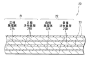
FIG. 2 shows an enlarged part of the spirally
リチウムを吸蔵および放出することが可能な正極材料としては、例えば、コバルト酸リチウム、ニッケル酸リチウム、あるいはこれらを含む固溶体(Li(Nix Coy Mnz )O2 ))(x,yおよびzの値は0<x<1,0<y<1,0<z<1,x+y+z=1である。)、またはスピネル構造を有するマンガン酸リチウム(LiMn2 O4 )あるいはその固溶体(Li(Mn2-v Niv )O4 )(vの値はv<2である。)などのリチウム複合酸化物、またはリン酸鉄リチウム(LiFePO4 )などのオリビン構造を有するリン酸化合物が好ましい。高いエネルギー密度を得ることができるからである。また、リチウムを吸蔵および放出することが可能な正極材料としては、例えば、酸化チタン,酸化バナジウムあるいは二酸化マンガンなどの酸化物、二硫化鉄,二硫化チタンあるいは硫化モリブデンなどの二硫化物、硫黄、ポリアニリンあるいはポリチオフェンなどの導電性高分子も挙げられる。 As a cathode material capable of inserting and extracting lithium, for example, lithium cobalt oxide, a solid solution containing lithium nickelate, or these (Li (Ni x Co y Mn z) O 2)) (x, y and z 0 <x <1, 0 <y <1, 0 <z <1, x + y + z = 1), or lithium manganate having a spinel structure (LiMn 2 O 4 ) or its solid solution (Li (Mn 2-v Ni v ) O 4 ) (value of v is v <2) or a phosphoric acid compound having an olivine structure such as lithium iron phosphate (LiFePO 4 ) is preferable. This is because a high energy density can be obtained. Examples of positive electrode materials capable of occluding and releasing lithium include oxides such as titanium oxide, vanadium oxide and manganese dioxide, disulfides such as iron disulfide, titanium disulfide and molybdenum sulfide, sulfur, Examples thereof include conductive polymers such as polyaniline and polythiophene.
負極22は、例えば、対向する一対の面を有する負極集電体22Aの両面に負極活物質層22Bが設けられた構造を有している。負極集電体22Aは、例えば、銅(Cu),ニッケルあるいはステンレスなどの金属材料により構成されている。
The
負極活物質層22Bは、リチウムを吸蔵および放出することが可能な負極材料のいずれか1種または2種以上を含んでおり、必要に応じて導電材あるいは結着材などを含んでいてもよい。リチウムを吸蔵および放出することが可能な負極材料としては、例えば、リチウムを吸蔵および放出することが可能であり、金属元素および半金属元素のうちの少なくとも1種を構成元素として含む材料が挙げられる。このような負極材料を用いれば、高いエネルギー密度を得ることができるので好ましい。この負極材料は金属元素あるいは半金属元素の単体でも合金でも化合物でもよく、またこれらの1種または2種以上の相を少なくとも一部に有するようなものでもよい。なお、本発明において、合金には2種以上の金属元素からなるものに加えて、1種以上の金属元素と1種以上の半金属元素とを含むものも含める。また、非金属元素を含んでいてもよい。その組織には固溶体,共晶(共融混合物),金属間化合物あるいはそれらのうちの2種以上が共存するものがある。
The negative electrode
この負極材料を構成する金属元素あるいは半金属元素としては、例えばリチウムと合金を形成可能な金属元素あるいは半金属元素が挙げられる。具体的には、マグネシウム(Mg),ホウ素(B),アルミニウム,ガリウム(Ga),インジウム(In),ケイ素,ゲルマニウム(Ge),スズ,鉛(Pb),ビスマス(Bi),カドミウム(Cd),銀(Ag),亜鉛(Zn),ハフニウム(Hf),ジルコニウム(Zr),イットリウム(Y),パラジウム(Pd)あるいは白金(Pt)などが挙げられる。このうち特に好ましいのは、ケイ素またはスズである。リチウムを吸蔵および放出する能力が大きく、高いエネルギー密度を得ることができるからである。 Examples of the metal element or metalloid element constituting the negative electrode material include a metal element or metalloid element capable of forming an alloy with lithium. Specifically, magnesium (Mg), boron (B), aluminum, gallium (Ga), indium (In), silicon, germanium (Ge), tin, lead (Pb), bismuth (Bi), cadmium (Cd) , Silver (Ag), zinc (Zn), hafnium (Hf), zirconium (Zr), yttrium (Y), palladium (Pd), or platinum (Pt). Of these, silicon or tin is particularly preferable. This is because the ability to occlude and release lithium is large, and a high energy density can be obtained.
このような負極材料としては、例えば、スズを第1の構成元素とし、スズに加えて第2の構成元素と第3の構成元素とを含むものが好ましい。第2の構成元素は、コバルト(Co),鉄,マグネシウム,チタン(Ti),バナジウム(V),クロム(Cr),マンガン(Mn),ニッケル,銅,亜鉛,ガリウム,ジルコニウム,ニオブ(Nb),モリブデン(Mo),銀,インジウム,セリウム(Ce),ハフニウム,タンタル(Ta),タングステン(W),ビスマスおよびケイ素からなる群のうちの少なくとも1種である。第3の構成元素は、ホウ素,炭素(C),アルミニウムおよびリン(P)からなる群のうちの少なくとも1種である。第2の元素および第3の元素を含むことにより、サイクル特性を向上させることができるからである。 As such a negative electrode material, for example, tin is a first constituent element, and a material containing a second constituent element and a third constituent element in addition to tin is preferable. The second constituent element is cobalt (Co), iron, magnesium, titanium (Ti), vanadium (V), chromium (Cr), manganese (Mn), nickel, copper, zinc, gallium, zirconium, niobium (Nb). , Molybdenum (Mo), silver, indium, cerium (Ce), hafnium, tantalum (Ta), tungsten (W), bismuth, and silicon. The third constituent element is at least one selected from the group consisting of boron, carbon (C), aluminum, and phosphorus (P). This is because the cycle characteristics can be improved by including the second element and the third element.
中でも、この負極材料としては、スズと、コバルトと、炭素とを構成元素として含み、炭素の含有量が9.9質量%以上29.7質量%以下であり、かつスズとコバルトとの合計に対するコバルトの割合Co/(Sn+Co)が30質量%以上70質量%以下であるCoSnC含有材料が好ましい。このような組成範囲において高いエネルギー密度を得ることができると共に、優れたサイクル特性を得ることができるからである。 Among these, as this negative electrode material, tin, cobalt, and carbon are included as constituent elements, the carbon content is 9.9 mass% or more and 29.7 mass% or less, and the total of tin and cobalt is A CoSnC-containing material having a cobalt ratio Co / (Sn + Co) of 30% by mass to 70% by mass is preferable. This is because a high energy density can be obtained in such a composition range, and excellent cycle characteristics can be obtained.
このCoSnC含有材料は、必要に応じて更に他の構成元素を含んでいてもよい。他の構成元素としては、例えば、ケイ素,鉄,ニッケル,クロム,インジウム,ニオブ,ゲルマニウム,チタン,モリブデン,アルミニウム,リン,ガリウムまたはビスマスが好ましく、2種以上を含んでいてもよい。容量またはサイクル特性を更に向上させることができるからである。 This CoSnC-containing material may further contain other constituent elements as necessary. As other constituent elements, for example, silicon, iron, nickel, chromium, indium, niobium, germanium, titanium, molybdenum, aluminum, phosphorus, gallium, or bismuth are preferable, and two or more kinds may be included. This is because the capacity or cycle characteristics can be further improved.
なお、このCoSnC含有材料は、スズと、コバルトと、炭素とを含む相を有しており、この相は結晶性の低いまたは非晶質な構造を有していることが好ましい。また、このCoSnC含有材料では、構成元素である炭素の少なくとも一部が、他の構成元素である金属元素または半金属元素と結合していることが好ましい。サイクル特性の低下はスズなどが凝集あるいは結晶化することによるものであると考えられるが、炭素が他の元素と結合することにより、そのような凝集あるいは結晶化を抑制することができるからである。 This CoSnC-containing material has a phase containing tin, cobalt, and carbon, and this phase preferably has a low crystallinity or an amorphous structure. In this CoSnC-containing material, it is preferable that at least a part of carbon as a constituent element is bonded to a metal element or a semimetal element as another constituent element. The decrease in cycle characteristics is thought to be due to the aggregation or crystallization of tin or the like, but this is because such aggregation or crystallization can be suppressed by combining carbon with other elements. .
元素の結合状態を調べる測定方法としては、例えばX線光電子分光法(X-ray Photoelectron Spectroscopy;XPS)が挙げられる。XPSでは、炭素の1s軌道(C1s)のピークは、グラファイトであれば、金原子の4f軌道(Au4f)のピークが84.0eVに得られるようにエネルギー較正された装置において、284.5eVに現れる。また、表面汚染炭素であれば、284.8eVに現れる。これに対して、炭素元素の電荷密度が高くなる場合、例えば炭素が金属元素または半金属元素と結合している場合には、C1sのピークは、284.5eVよりも低い領域に現れる。すなわち、CoSnC含有材料について得られるC1sの合成波のピークが284.5eVよりも低い領域に現れる場合には、CoSnC含有材料に含まれる炭素の少なくとも一部が他の構成元素である金属元素または半金属元素と結合している。 As a measuring method for examining the bonding state of elements, for example, X-ray photoelectron spectroscopy (XPS) can be cited. In XPS, the peak of the carbon 1s orbital (C1s) appears at 284.5 eV in an energy calibrated apparatus so that the peak of the gold atom 4f orbital (Au4f) is obtained at 84.0 eV if it is graphite. . Moreover, if it is surface contamination carbon, it will appear at 284.8 eV. On the other hand, when the charge density of the carbon element increases, for example, when carbon is bonded to a metal element or a metalloid element, the C1s peak appears in a region lower than 284.5 eV. That is, when the peak of the synthetic wave of C1s obtained for the CoSnC-containing material appears in a region lower than 284.5 eV, at least a part of the carbon contained in the CoSnC-containing material is a metal element or a half of other constituent elements. Combined with metal elements.
なお、XPS測定では、スペクトルのエネルギー軸の補正に、例えばC1sのピークを用いる。通常、表面には表面汚染炭素が存在しているので、表面汚染炭素のC1sのピークを284.8eVとし、これをエネルギー基準とする。XPS測定では、C1sのピークの波形は、表面汚染炭素のピークとCoSnC含有材料中の炭素のピークとを含んだ形として得られるので、例えば市販のソフトウエアを用いて解析することにより、表面汚染炭素のピークと、CoSnC含有材料中の炭素のピークとを分離する。波形の解析では、最低束縛エネルギー側に存在する主ピークの位置をエネルギー基準(284.8eV)とする。 In XPS measurement, for example, the C1s peak is used to correct the energy axis of the spectrum. Usually, since surface-contaminated carbon exists on the surface, the C1s peak of the surface-contaminated carbon is set to 284.8 eV, which is used as an energy standard. In the XPS measurement, the waveform of the C1s peak is obtained as a shape including the surface contamination carbon peak and the carbon peak in the CoSnC-containing material. For example, by analyzing using a commercially available software, the surface contamination The carbon peak and the carbon peak in the CoSnC-containing material are separated. In the waveform analysis, the position of the main peak existing on the lowest bound energy side is used as the energy reference (284.8 eV).
リチウムを吸蔵および放出することが可能な負極材料としては、また例えば、黒鉛,難黒鉛化性炭素あるいは易黒鉛化性炭素などの炭素材料を用いてもよく、また、これらの炭素材料と、上述した負極材料とを共に用いるようにしてもよい。炭素材料は、リチウムの吸蔵および放出に伴う結晶構造の変化が非常に少なく、例えば上述した負極材料と共に用いるようにすれば、高エネルギー密度を得ることができると共に、優れたサイクル特性を得ることができ、更に導電材としても機能するので好ましい。 As a negative electrode material capable of inserting and extracting lithium, for example, a carbon material such as graphite, non-graphitizable carbon, or graphitizable carbon may be used. The negative electrode material may be used together. The carbon material has very little change in crystal structure due to insertion and extraction of lithium. For example, when used together with the negative electrode material described above, a high energy density and excellent cycle characteristics can be obtained. It is also preferable because it functions as a conductive material.
なお、この二次電池では、正極活物質とリチウムを吸蔵および放出することが可能な負極材料との量を調整することにより、正極活物質による充電容量よりも、リチウムを吸蔵および放出することが可能な負極材料による充電容量の方が大きくなるようにし、完全充電時においても負極22にリチウム金属が析出しないようになっている。
In this secondary battery, by adjusting the amount of the positive electrode active material and the negative electrode material capable of inserting and extracting lithium, lithium can be inserted and released rather than the charge capacity of the positive electrode active material. The charge capacity of the possible negative electrode material is increased so that lithium metal does not deposit on the
セパレータ23は、正極21と負極22とを隔離し、両極の接触による電流の短絡を防止しつつ、リチウムイオンを通過させるものである。このセパレータ23は、例えば、ポリテトラフルオロエチレン、ポリプロピレンあるいはポリエチレンなどよりなる合成樹脂製の多孔質膜、またはセラミック製の多硬質膜により構成されており、これらの2種以上の多孔質膜を積層した構造とされていてもよい。
The
セパレータ23には、本実施の形態に係る電解液が含浸されている。
The
この二次電池は、例えば、次のようにして製造することができる。 For example, the secondary battery can be manufactured as follows.
まず、例えば、正極集電体21Aに正極活物質層21Bを形成し正極21を作製する。正極活物質層21Bは、例えば、正極活物質の粉末と導電材と結着材とを混合して正極合剤を調製したのち、この正極合剤をN−メチル−2−ピロリドンなどの溶剤に分散させてペースト状の正極合剤スラリーとし、この正極合剤スラリーを正極集電体21Aに塗布し乾燥させ、圧縮成型することにより形成する。また、例えば、正極21と同様にして、負極集電体22Aに負極活物質層22Bを形成し負極22を作製する。
First, for example, the positive electrode
次いで、正極集電体21Aに正極リード25を溶接などにより取り付けると共に、負極集電体22Aに負極リード26を溶接などにより取り付ける。続いて、正極21と負極22とをセパレータ23を介して巻回し、正極リード25の先端部を安全弁機構15に溶接すると共に、負極リード26の先端部を電池缶11に溶接して、巻回した正極21および負極22を一対の絶縁板12,13で挟み電池缶11の内部に収納する。正極21および負極22を電池缶11の内部に収納したのち、電解液を電池缶11の内部に注入し、セパレータ23に含浸させる。そののち、電池缶11の開口端部に電池蓋14,安全弁機構15および熱感抵抗素子16をガスケット17を介してかしめることにより固定する。これにより、図1,2に示した二次電池が完成する。
Next, the
この二次電池では、充電を行うと、例えば、正極21からリチウムイオンが放出され、電解液を介して負極22に吸蔵される。一方、放電を行うと、例えば、負極22からリチウムイオンが放出され、電解液を介して正極21に吸蔵される。その際、電解液に環状のイミド塩が含まれているので、電解液の分解反応が抑制される。
In the secondary battery, when charged, for example, lithium ions are extracted from the
このようにこの二次電池によれば、環状のイミド塩を含むようにしたので、電解液の分解反応を抑制することができ、サイクル特性を向上させることができる。また、ハロゲン原子を有する環状の炭酸エステル誘導体を含むようにすれば、電解液の分解反応を更に抑制することができ、サイクル特性をより向上させることができる。 As described above, according to the secondary battery, since the cyclic imide salt is included, the decomposition reaction of the electrolytic solution can be suppressed, and the cycle characteristics can be improved. In addition, if a cyclic carbonate derivative having a halogen atom is included, the decomposition reaction of the electrolytic solution can be further suppressed, and the cycle characteristics can be further improved.
特に、負極22に、リチウムを吸蔵および放出することが可能であり、構成元素として金属元素および半金属元素のうちの少なくとも1種を含む材料を用いる場合には、負極22の活性が高く電解液が分解されやすいので、より高い効果を得ることができる。
In particular, when the
また、電解液における環状のイミド塩の含有量を0.1質量%以上31質量%以下の範囲内にするようにすれば、より高い効果を得ることができる。 Further, if the content of the cyclic imide salt in the electrolytic solution is in the range of 0.1% by mass or more and 31% by mass or less, a higher effect can be obtained.
更に、電解液に不飽和結合を有する環状の炭酸エステルおよびスルトンからなる群のうちの少なくとも1種を含むようにすれば、高温におけるサイクル特性も向上させることができる。 Furthermore, if at least one member selected from the group consisting of cyclic carbonates having an unsaturated bond and sultone is included in the electrolyte, cycle characteristics at high temperatures can be improved.
(第2の二次電池)
第2の二次電池は、負極の構成が異なることを除き、他は第1の二次電池と同様の構成・作用および効果を有しており、同様にして製造することができる。よって、図1および図2を参照し、対応する構成要素には同一の符号を付して同一部分の説明は省略する。
(Secondary secondary battery)
The second secondary battery has the same configuration, operation, and effects as the first secondary battery except that the configuration of the negative electrode is different, and can be manufactured in the same manner. Therefore, with reference to FIG. 1 and FIG. 2, the same code | symbol is attached | subjected to a corresponding component and description of the same part is abbreviate | omitted.
負極22は、第1の二次電池と同様に、負極集電体22Aの両面に負極活物質層22Bが設けられた構造を有している。負極活物質層22Bは、例えば、スズまたはケイ素を構成元素として含む負極活物質を含有している。具体的には、例えば、スズの単体,合金,あるいは化合物、またはケイ素の単体,合金,あるいは化合物を含有しており、それらの2種以上を含有していてもよい。
Similar to the first secondary battery, the
また、負極活物質層22Bは、例えば、気相法,液相法,溶射法あるいは焼成法、またはそれらの2以上の方法を用いて形成されたものであり、負極活物質層22Bと負極集電体22Aとが界面の少なくとも一部において合金化していることが好ましい。具体的には、界面において負極集電体22Aの構成元素が負極活物質層22Bに、または負極活物質の構成元素が負極集電体22Aに、またはそれらが互いに拡散していることが好ましい。充放電に伴う負極活物質層22Bの膨張・収縮による破壊を抑制することができると共に、負極活物質層22Bと負極集電体22Aとの間の電子伝導性を向上させることができるからである。
The negative electrode
なお、気相法としては、例えば、物理堆積法あるいは化学堆積法を用いることができ、具体的には、真空蒸着法,スパッタ法,イオンプレーティング法,レーザーアブレーション法,熱化学気相成長(CVD;Chemical Vapor Deposition )法,あるいはプラズマ化学気相成長法などが挙げられる。液相法としては、電気鍍金あるいは無電解鍍金などの公知の手法を用いることができる。焼成法というのは、例えば、粒子状の負極活物質を結着材などと混合して溶剤に分散させ、塗布したのち、結着材などの融点よりも高い温度で熱処理する方法である。焼成法に関しても公知の手法が利用可能であり、例えば、雰囲気焼成法,反応焼成法あるいはホットプレス焼成法が挙げられる。 As the vapor phase method, for example, a physical deposition method or a chemical deposition method can be used. Specifically, a vacuum deposition method, a sputtering method, an ion plating method, a laser ablation method, a thermal chemical vapor deposition ( CVD (Chemical Vapor Deposition) method or plasma chemical vapor deposition method may be used. As the liquid phase method, a known method such as electroplating or electroless plating can be used. The firing method is, for example, a method in which a particulate negative electrode active material is mixed with a binder, dispersed in a solvent, applied, and then heat-treated at a temperature higher than the melting point of the binder. A known method can also be used for the firing method, for example, an atmospheric firing method, a reactive firing method, or a hot press firing method.
(第3の二次電池)
第3の二次電池は、負極22の容量がリチウムの析出および溶解による容量成分により表される、いわゆるリチウム金属二次電池である。この二次電池は、負極活物質層22Bをリチウム金属により構成したことを除き、他は第1の二次電池と同様の構成を有しており、同様にして製造することができる。従って、図1および図2を参照し、対応する構成要素には同一の符号を付して同一部分の説明は省略する。
(Third secondary battery)
The third secondary battery is a so-called lithium metal secondary battery in which the capacity of the
すなわち、この二次電池は、負極活物質としてリチウム金属を用いており、これにより高いエネルギー密度を得ることができるようになっている。負極活物質層22Bは、組み立て時から既に有するように構成してもよいが、組み立て時には存在せず、充電時に析出したリチウム金属により構成するようにしてもよい。また、負極活物質層22Bを集電体としても利用し、負極集電体22Aを削除するようにしてもよい。
That is, this secondary battery uses lithium metal as a negative electrode active material, and thereby can obtain a high energy density. The negative electrode
なお、この二次電池では、電解液に環状のイミド塩と共に、ハロゲン原子を有する環状の炭酸エステル誘導体を含むことが好ましく、更に上述した他の構成成分を含んでいてもよい。これらを共に含むことにより、いずれか一方のみの場合に比べて、溶媒の分解反応を抑制する効果が飛躍的に向上するからである。この場合、溶媒におけるハロゲン原子を有する環状の炭酸エステル誘導体の含有量は50体積%以下であることが好ましい。より高い効果を得ることができるからである。 In this secondary battery, it is preferable that the electrolytic solution includes a cyclic carbonate ester derivative having a halogen atom together with a cyclic imide salt, and may further include other components described above. This is because by including both of these, the effect of suppressing the decomposition reaction of the solvent is greatly improved as compared with the case of only one of them. In this case, the content of the cyclic carbonate derivative having a halogen atom in the solvent is preferably 50% by volume or less. This is because a higher effect can be obtained.
この二次電池では、充電を行うと、例えば、正極21からリチウムイオンが放出され、電解液を介して、負極集電体22Aの表面にリチウム金属となって析出する。放電を行うと、例えば、負極活物質層22Bからリチウム金属がリチウムイオンとなって溶出し、電解液を介して正極21に吸蔵される。このように、充放電に伴い負極22ではリチウム金属の析出および溶解が繰り返され、負極22の活性が非常に高くなっているが、この二次電池では、電解液に環状のイミド塩とハロゲン原子を有する環状の炭酸エステル誘導体とが含まれているので、負極22における電解液の分解反応が抑制される。よって、負極22におけるリチウムの充放電効率が向上する。
In the secondary battery, when charged, for example, lithium ions are extracted from the
このようにこの二次電池によれば、電解液に環状のイミド塩とハロゲン原子を有する環状の炭酸エステル誘導体とを含むようにしたので、負極22における電解液の分解反応を抑制することができる。よって、負極22における充放電効率が向上し、サイクル特性を向上させることができる。
Thus, according to this secondary battery, since the electrolytic solution contains the cyclic imide salt and the cyclic carbonate derivative having a halogen atom, the decomposition reaction of the electrolytic solution in the
(第4の二次電池)
第4の二次電池は、負極の容量が電極反応物質であるリチウムの吸蔵および放出による容量成分と、リチウムの析出および溶解による容量成分とを含み、かつその和により表されるものである。この二次電池は、負極活物質層22Bの構成が異なることを除き、他は第1の二次電池と同様の構成を有しており、同様にして製造することができる。従って、図1および図2を参照し、対応する構成要素には同一の符号を付して同一部分の説明は省略する。
(Fourth secondary battery)
In the fourth secondary battery, the capacity of the negative electrode includes a capacity component due to insertion and extraction of lithium as an electrode reactant, and a capacity component due to precipitation and dissolution of lithium, and is represented by the sum thereof. This secondary battery has the same configuration as that of the first secondary battery except that the configuration of the negative electrode
負極活物質層22Bは、負極活物質として、リチウムを吸蔵および放出することが可能な1種または2種以上の負極材料を含んでおり、必要に応じて結着材を含んでいてもよい。このような負極材料としては、例えば、第1の実施の形態でも説明した炭素材料や、または、リチウムと合金を形成可能な金属元素あるいは半金属元素を構成元素として含む材料が挙げられる。中でも、炭素材料を用いるようにすれば、優れたサイクル特性を得ることができるので好ましい。
The negative electrode
このリチウムを吸蔵および放出することが可能な負極材料の量は、この負極材料による充電容量が正極21の充電容量よりも小さくなるように調節されている。これにより、この二次電池では、充電の過程において、開回路電圧(すなわち電池電圧)が過充電電圧よりも低い時点で負極22にリチウム金属が析出し始めるようになっている。
The amount of the negative electrode material capable of inserting and extracting lithium is adjusted so that the charge capacity of the negative electrode material is smaller than the charge capacity of the
なお、過充電電圧というのは、電池が過充電状態になった時の開回路電圧を指し、例えば、日本蓄電池工業会(電池工業会)の定めた指針の一つである「リチウム二次電池安全性評価基準ガイドライン」(SBA G1101)に記載され定義される「完全充電」された電池の開回路電圧よりも高い電圧を指す。また換言すれば、各電池の公称容量を求める際に用いた充電方法、標準充電方法、もしくは推奨充電方法を用いて充電した後の開回路電圧よりも高い電圧を指す。例えば、開回路電圧が4.2Vの時に完全充電となる場合には、開回路電圧が0V以上4.2V以下の範囲内の一部においてリチウムを吸蔵および放出可能な負極材料の表面にリチウム金属が析出している。従って、この二次電池では、リチウムを吸蔵および放出可能な負極材料とリチウム金属との両方が負極活物質として機能し、リチウムを吸蔵および放出可能な負極材料はリチウム金属が析出する際の基材となっている。これによりこの二次電池では、高いエネルギー密度を得ることができると共に、サイクル特性および急速充電特性を向上させることができるようになっている。 The overcharge voltage refers to the open circuit voltage when the battery is overcharged. For example, the “lithium secondary battery” is one of the guidelines established by the Japan Storage Battery Industry Association (Battery Industry Association). Refers to a voltage that is higher than the open circuit voltage of a “fully charged” battery as defined and defined in the “Safety Evaluation Criteria Guidelines” (SBA G1101). In other words, it refers to a voltage higher than the open circuit voltage after charging using the charging method, standard charging method, or recommended charging method used when determining the nominal capacity of each battery. For example, when full charge occurs when the open circuit voltage is 4.2 V, lithium metal is formed on the surface of the negative electrode material capable of inserting and extracting lithium in a part of the open circuit voltage in the range of 0 V to 4.2 V. Is deposited. Therefore, in this secondary battery, both the negative electrode material capable of occluding and releasing lithium and lithium metal function as the negative electrode active material, and the negative electrode material capable of occluding and releasing lithium is a base material on which the lithium metal is deposited. It has become. Thereby, in this secondary battery, it is possible to obtain a high energy density, and to improve cycle characteristics and quick charge characteristics.
また、この二次電池では、第3の二次電池と同様に、電解液に環状のイミド塩と共に、ハロゲン原子を有する環状の炭酸エステル誘導体を含むことが好ましく、更に上述した他の構成成分を含んでいてもよい。いずれか一方のみの場合に比べて、得られる効果が飛躍的に向上するからである。この場合、溶媒におけるハロゲン原子を有する環状の炭酸エステル誘導体の含有量は50体積%以下であることが好ましい。より高い効果を得ることができるからである。 In this secondary battery, as in the third secondary battery, it is preferable that the electrolyte contains a cyclic carbonate ester derivative having a halogen atom together with a cyclic imide salt. May be included. This is because the obtained effect is dramatically improved as compared with the case of only one of them. In this case, the content of the cyclic carbonate derivative having a halogen atom in the solvent is preferably 50% by volume or less. This is because a higher effect can be obtained.
この二次電池では、充電を行うと、正極21からリチウムイオンが放出され、電解液を介して、まず、負極22に含まれるリチウムを吸蔵および放出可能な負極材料に吸蔵される。更に充電を続けると、開回路電圧が過充電電圧よりも低い状態において、リチウムを吸蔵および放出可能な負極材料の表面にリチウム金属が析出し始める。そののち、充電を終了するまで負極22にはリチウム金属が析出し続ける。次いで、放電を行うと、まず、負極22に析出したリチウム金属がイオンとなって溶出し、電解液を介して、正極21に吸蔵される。更に放電を続けると、負極22中のリチウムを吸蔵および放出可能な負極材料からリチウムイオンが放出され、電解液を介して正極21に吸蔵される。このようにこの二次電池でも、負極22においてリチウム金属の析出および溶解が繰り返されるので、負極22の活性が非常に高くなっているが、電解液に環状のイミド塩とハロゲン原子を有する環状の炭酸エステル誘導体とを含んでいるので、負極22における電解液の分解反応が抑制される。よって、負極22におけるリチウムの充放電効率が向上する。
In the secondary battery, when charged, lithium ions are released from the
このようにこの二次電池においても、電解液に環状のイミド塩とハロゲン原子を有する環状の炭酸エステル誘導体とを含むようにしたので、負極22における電解液の分解反応を抑制することができる。よって、負極22における充放電効率が向上し、サイクル特性を向上させることができる。
As described above, also in this secondary battery, the electrolytic solution contains the cyclic imide salt and the cyclic carbonate derivative having a halogen atom, so that the decomposition reaction of the electrolytic solution in the
(第5の二次電池)
図3は、第5の二次電池の構成を表すものである。この二次電池は、いわゆるラミネートフィルム型といわれるものであり、正極リード31および負極リード32が取り付けられた巻回電極体30をフィルム状の外装部材40の内部に収容したものである。
(Fifth secondary battery)
FIG. 3 shows the configuration of the fifth secondary battery. This secondary battery is a so-called laminate film type, and has a
正極リード31および負極リード32は、それぞれ、外装部材40の内部から外部に向かい例えば同一方向に導出されている。正極リード31および負極リード32は、例えば、アルミニウム,銅,ニッケルあるいはステンレスなどの金属材料によりそれぞれ構成されており、それぞれ薄板状または網目状とされている。
The
外装部材40は、例えば、ナイロンフィルム,アルミニウム箔およびポリエチレンフィルムをこの順に貼り合わせた矩形状のアルミラミネートフィルムにより構成されている。外装部材40は、例えば、ポリエチレンフィルム側と巻回電極体30とが対向するように配設されており、各外縁部が融着あるいは接着剤により互いに密着されている。外装部材40と正極リード31および負極リード32との間には、外気の侵入を防止するための密着フィルム41が挿入されている。密着フィルム41は、正極リード31および負極リード32に対して密着性を有する材料、例えば、ポリエチレン,ポリプロピレン,変性ポリエチレンあるいは変性ポリプロピレンなどのポリオレフィン樹脂により構成されている。
The
なお、外装部材40は、上述したアルミラミネートフィルムに代えて、他の構造を有するラミネートフィルム,ポリプロピレンなどの高分子フィルムあるいは金属フィルムにより構成するようにしてもよい。
The
図4は、図3に示した巻回電極体30のI−I線に沿った断面構造を表すものである。電極巻回体30は、正極33と負極34とをセパレータ35および電解質層36を介して積層し、巻回したものであり、最外周部は保護テープ37により保護されている。
FIG. 4 shows a cross-sectional structure taken along line II of the spirally
正極33は、正極集電体33Aの両面に正極活物質層33Bが設けられた構造を有している。負極34は、負極集電体34Aの両面に負極活物質層34Bが設けられた構造を有しており、負極活物質層34Bと正極活物質層33Bとが対向するように配置されている。正極集電体33A,正極活物質層33B,負極集電体34A,負極活物質層34Bおよびセパレータ35の構成は、上述した第1から第4の二次電池における正極集電体21A,正極活物質層21B,負極集電体22A,負極活物質層22Bおよびセパレータ23と同様である。
The
電解質層36は、本実施の形態に係る電解液と、この電解液を保持する保持体となる高分子化合物とを含み、いわゆるゲル状となっている。ゲル状の電解質は高いイオン伝導率を得ることができると共に、電池の漏液を防止することができるので好ましい。高分子化合物としては、例えば、ポリエチレンオキサイドあるいはポリエチレンオキサイドを含む架橋体などのエーテル系高分子化合物、ポリメタクリレートなどのエステル系高分子化合物あるいはアクリレート系高分子化合物、またはポリフッ化ビニリデンあるいはフッ化ビニリデンとヘキサフルオロプロピレンとの共重合体などのフッ化ビニリデンの重合体が挙げられ、これらのうちのいずれか1種または2種以上が混合して用いられる。特に、酸化還元安定性の観点からは、フッ化ビニリデンの重合体などのフッ素系高分子化合物を用いることが望ましい。
The
この二次電池は、例えば、次のようにして製造することができる。 For example, the secondary battery can be manufactured as follows.
まず、正極33および負極34のそれぞれに、電解液と、高分子化合物と、混合溶剤とを含む前駆溶液を塗布し、混合溶剤を揮発させて電解質層36を形成する。次いで、正極集電体33Aに正極リード31を取り付けると共に、負極集電体34Aに負極リード32を取り付ける。続いて、電解質層36が形成された正極33と負極34とをセパレータ35を介して積層し積層体としたのち、この積層体をその長手方向に巻回して、最外周部に保護テープ37を接着して巻回電極体30を形成する。そののち、例えば、外装部材40の間に巻回電極体30を挟み込み、外装部材40の外縁部同士を熱融着などにより密着させて封入する。その際、正極リード31および負極リード32と外装部材40との間には密着フィルム41を挿入する。これにより、図3,4に示した二次電池が完成する。
First, a precursor solution containing an electrolytic solution, a polymer compound, and a mixed solvent is applied to each of the
また、この二次電池は、次のようにして作製してもよい。まず、上述したようにして正極33および負極34を作製し、正極33および負極34に正極リード31および負極リード32を取り付けたのち、正極33と負極34とをセパレータ35を介して積層して巻回し、最外周部に保護テープ37を接着して、巻回電極体30の前駆体である巻回体を形成する。次いで、この巻回体を外装部材40に挟み、一辺を除く外周縁部を熱融着して袋状とし、外装部材40の内部に収納する。続いて、電解液と、高分子化合物の原料であるモノマーと、重合開始剤と、必要に応じて重合禁止剤などの他の材料とを含む電解質用組成物を用意し、外装部材40の内部に注入したのち、外装部材40の開口部を熱融着して密封する。そののち、熱を加えてモノマーを重合させて高分子化合物とすることによりゲル状の電解質層36を形成し、図3,4に示した二次電池を組み立てる。
Further, this secondary battery may be manufactured as follows. First, the
この二次電池の作用および効果は、上述した第1から第4の二次電池と同様である。 The operation and effect of this secondary battery are the same as those of the first to fourth secondary batteries described above.
(第6の二次電池)
第6の二次電池は、正極活物質と負極活物質との量を調節することにより、一対の正極および負極当たりの完全充電時における開回路電圧(すなわち電池電圧)を4.25V以上6.00V以下の範囲内としたことを除き、他は第1から第5の二次電池と同様の構成を有しており、同様にして製造することができる。
(Sixth secondary battery)
In the sixth secondary battery, the open circuit voltage (that is, the battery voltage) at the time of full charge per pair of the positive electrode and the negative electrode is adjusted to 4.25 V or more by adjusting the amounts of the positive electrode active material and the negative electrode active material. Except for being in the range of 00 V or less, the rest has the same configuration as the first to fifth secondary batteries, and can be manufactured in the same manner.
この二次電池では、完全充電時における開回路電圧が4.20Vの電池よりも、同じ正極活物質であっても、単位質量当たりのリチウムの放出量が多くなるので、それに応じて正極活物質と負極活物質との量が調整されており、これにより高いエネルギー密度が得られるようになっている。 In this secondary battery, even if the positive electrode active material is the same as that of the battery having an open circuit voltage of 4.20 V when fully charged, the amount of lithium released per unit mass is increased. Accordingly, the positive electrode active material And the negative electrode active material are adjusted so that a high energy density can be obtained.
なお、負極活物質としては、リチウム金属、あるいはリチウムを吸蔵および放出することが可能な炭素材料が好ましい。これらは充放電電位が低いので電池のエネルギー密度を容易に向上させることができるからである。 In addition, as a negative electrode active material, the carbon material which can occlude and discharge | release lithium is preferable. This is because the energy density of the battery can be easily improved because the charge / discharge potential is low.
この二次電池では、充電を行うと、例えば、正極21からリチウムイオンが放出され、電解液を介して負極22に吸蔵される。一方、放電を行うと、例えば、負極22からリチウムイオンが放出され、電解液を介して正極21に吸蔵される。ここでは、充電時の電池電圧が4.25V以上となっているので、電解液が分解されやすくなっているが、上述したように環状のイミド塩が含まれているので、電解液の分解反応が抑制される。
In the secondary battery, when charged, for example, lithium ions are extracted from the
この二次電池の効果は、第1から第5の二次電池と同様である。 The effect of this secondary battery is the same as that of the first to fifth secondary batteries.
更に、本発明の具体的な実施例について詳細に説明する。 Further, specific embodiments of the present invention will be described in detail.
(実験例1−1〜1−5)
図5に示したコイン型の二次電池を作製した。この二次電池は、正極51と、負極52とを電解液を含浸させたセパレータ53を介して積層し、外装缶54と外装カップ55との間に挟み、ガスケット56を介してかしめたものである。まず、正極活物質としてリチウムコバルト複合酸化物(LiCoO2 )94質量部と、導電材としてグラファイト3質量部と、結着材としてポリフッ化ビニリデン3質量部とを混合したのち、溶剤としてN−メチル−2−ピロリドンを添加し正極合剤スラリーを得た。次いで、得られた正極合剤スラリーを、厚み20μmのアルミニウム箔よりなる正極集電体51Aに均一に塗布し乾燥させて厚み70μmの正極活物質層51Bを形成した。そののち、正極活物質層51Bが形成された正極集電体51Aを直径15mmの円形に打ち抜き、正極51を作製した。
( Experimental Examples 1-1 to 1-5)
The coin-type secondary battery shown in FIG. 5 was produced. This secondary battery is formed by laminating a
また、負極活物質としてケイ素を用い、厚み15μmの銅箔よりなる負極集電体52Aの上にスパッタ法により厚み5μmのケイ素よりなる負極活物質層52Bを形成した。そののち、負極活物質層52Bが形成された負極集電体52Aを直径16mmの円形に打ち抜き、負極52を作製した。その際、正極活物質と負極活物質との充填量を調節し、完全充電時における開回路電圧(すなわち、電池電圧)を4.20Vとなるようにすると共に、充電の途中で負極52にリチウム金属が析出しないようにして、負極52の容量がリチウムの吸蔵および放出による容量成分により表されるようにした。 Further, silicon was used as the negative electrode active material, and a negative electrode active material layer 52B made of silicon having a thickness of 5 μm was formed on the negative electrode current collector 52A made of copper foil having a thickness of 15 μm by a sputtering method. After that, the negative electrode current collector 52A on which the negative electrode active material layer 52B was formed was punched into a circle having a diameter of 16 mm to produce the negative electrode 52. At that time, the filling amount of the positive electrode active material and the negative electrode active material is adjusted so that the open circuit voltage (that is, the battery voltage) at the time of full charge is 4.20 V, and lithium is added to the negative electrode 52 during the charge. The capacity of the negative electrode 52 was represented by a capacity component due to insertion and extraction of lithium so that no metal was deposited.
次いで、正極51と負極52とを厚み25μmの微多孔性ポリプロピレンフィルムよりなるセパレータ53を介して積層したのち、セパレータ53に電解液0.1gを注液して、これらをステンレスよりなる外装カップ55と外装缶54との中に入れ、それらをかしめることにより、図5に示した二次電池を得た。電解液は、実験例1−1では、溶媒としての炭酸エチレン(EC)および炭酸ジメチル(DMC)と、電解質塩としての六フッ化リン酸リチウムとを、炭酸エチレン:炭酸ジメチル:六フッ化リン酸リチウム=42:42:15の質量比で混合し、更に、環状のイミド塩を1質量%となるように添加して調製した。また、実験例1−2では、溶媒としてハロゲン原子を有する環式炭酸エステル誘導体である4−クロロ−1,3−ジオキソラン−2−オン(ClEC)と炭酸ジメチルと、電解質塩として六フッ化リン酸リチウムとを、4−クロロ−1,3−ジオキソラン−2−オン:炭酸ジメチル:六フッ化リン酸リチウム=42:42:15の質量比で混合し、更に、環状のイミド塩を1質量%となるように添加して調製した。更に、実験例1−3〜1−5では、溶媒としてハロゲン原子を有する環式炭酸エステル誘導体である4−フルオロ−1,3−ジオキソラン−2−オン(FEC)と炭酸ジメチルと、電解質塩として六フッ化リン酸リチウムとを、4−フルオロ−1,3−ジオキソラン−2−オン:炭酸ジメチル:六フッ化リン酸リチウム=42:42:15の質量比で混合し、更に、環状のイミド塩を1質量%となるように添加して調製した。環状のイミド塩は、実験例1−1〜1−3では化6(1)に示した1,1,2,2,3,3−ヘキサフルオロプロパン−1,3−ジスルホンイミドリチウムとし、実験例1−4では化6(2)に示した2,2,3,3,4,4−ヘキサフルオログルタルイミドリチウムとし、実験例1−5では化6(3)に示したオルト−スルホベンズイミドリチウムとした。
Next, the
実験例1−1〜1−5に対する比較例1−1〜1−3として、環状のイミド塩を添加しなかったことを除き、他は実験例1−1〜1−5と同様にして二次電池を作製した。具体的には、電解液は、比較例1−1では、炭酸エチレンと、炭酸ジメチルと、六フッ化リン酸リチウムとを、炭酸エチレン:炭酸ジメチル:六フッ化リン酸リチウム=42:42:15の質量比で混合したものとし、比較例1−2では、4−クロロ−1,3−ジオキソラン−2−オンと、炭酸ジメチルと、六フッ化リン酸リチウムとを、4−クロロ−1,3−ジオキソラン−2−オン:炭酸ジメチル:六フッ化リン酸リチウム=42:42:15の質量比で混合したものとし、比較例1−3では、4−フルオロ−1,3−ジオキソラン−2−オンと、炭酸ジメチルと、六フッ化リン酸リチウムとを、4−フルオロ−1,3−ジオキソラン−2−オン:炭酸ジメチル:六フッ化リン酸リチウム=42:42:15の質量比で混合したものとした。 As Comparative Examples 1-1 to 1-3 with respect to Experimental Examples 1-1 to 1-5, except that no cyclic imide salt was added, the rest was the same as Experimental Examples 1-1 to 1-5. A secondary battery was produced. Specifically, in Comparative Example 1-1, the electrolytic solution was ethylene carbonate, dimethyl carbonate, and lithium hexafluorophosphate, ethylene carbonate: dimethyl carbonate: lithium hexafluorophosphate = 42: 42: In Comparative Example 1-2, 4-chloro-1,3-dioxolan-2-one, dimethyl carbonate, and lithium hexafluorophosphate are mixed with 4-chloro-1 , 3-dioxolan-2-one: dimethyl carbonate: lithium hexafluorophosphate = 42: 42: 15, and in Comparative Example 1-3, 4-fluoro-1,3-dioxolane- The mass ratio of 2-one, dimethyl carbonate, and lithium hexafluorophosphate to 4-fluoro-1,3-dioxolan-2-one: dimethyl carbonate: lithium hexafluorophosphate = 42: 42: 15 And mixed with .
得られた実験例1−1〜1−5および比較例1−1〜1−3の二次電池について、25℃の環境下において、1.77mAで4.2Vを上限として12時間充電し、その後10分間休止して1.77mAで2.5Vに達するまで放電するという充放電を繰り返し、50サイクル目の放電容量維持率を求めた。50サイクル目の放電容量維持率は、(50サイクル目の放電容量/初回放電容量)×100(%)として計算した。結果を表1に示す。 About the obtained secondary batteries of Experimental Examples 1-1 to 1-5 and Comparative Examples 1-1 to 1-3, the battery was charged for 12 hours with an upper limit of 4.2 V at 1.77 mA in an environment of 25 ° C. Thereafter, charging / discharging of 10 minutes after stopping and discharging at 1.77 mA until reaching 2.5 V was repeated, and the discharge capacity maintenance rate at the 50th cycle was determined. The discharge capacity retention ratio at the 50th cycle was calculated as (discharge capacity at the 50th cycle / initial discharge capacity) × 100 (%). The results are shown in Table 1.
表1から分かるように、環状のイミド塩を用いた実験例1−1,1−2,1−3〜1−5によれば、これを用いていない比較例1−1,1−2,1−3よりも、放電容量維持率について、それぞれ高い値が得られた。また、4−クロロ−1,3−ジオキソラン−2−オンまたは4−フルオロ−1,3−ジオキソラン−2−オンを用いた実験例1−2〜1−5、特に4−フルオロ−1,3−ジオキソラン−2−オンを用いた実験例1−3〜1−5において、高い効果が観られた。 As can be seen from Table 1, according to Experimental Examples 1-1, 1-2, 1-3, and 1-5 using cyclic imide salts, Comparative Examples 1-1, 1-2, not using this, A higher value was obtained for the discharge capacity retention rate than for 1-3. Also, Experimental Examples 1-2 to 1-5 using 4-chloro-1,3-dioxolan-2-one or 4-fluoro-1,3-dioxolan-2-one, particularly 4-fluoro-1,3 In Experimental Examples 1-3 to 1-5 using -dioxolan-2-one, a high effect was observed.
すなわち、電解液に環状のイミド塩を含むようにすれば、サイクル特性を向上させることができ、更に、ハロゲン原子を有する環状の炭酸エステル誘導体を含むようにすれば好ましいことが分かった。 That is, it has been found that if the electrolyte solution contains a cyclic imide salt, the cycle characteristics can be improved, and further, if a cyclic carbonate derivative having a halogen atom is contained, it is preferable.
(実験例2−1〜2−5,3−1〜3−5)
実験例2−1〜2−5として、負極活物質にスズを用い、厚み15μmの銅箔よりなる負極集電体52Aの上に蒸着法により厚み5μmのスズよりなる負極活物質層52Bを形成したことを除き、他は実験例1−1〜1−5と同様にしてコイン型の二次電池を作製した。その際、正極活物質と負極活物質との充填量を調節し、完全充電時における開回路電圧を4.20Vとなるようにすると共に、充電の途中で負極52にリチウム金属が析出しないようにして、負極52の容量がリチウムの吸蔵および放出による容量成分により表されるようにした。
( Experimental Examples 2-1 to 2-5, 3-1 to 3-5)
As Experimental Examples 2-1 to 2-5, tin is used as the negative electrode active material, and the negative electrode active material layer 52B made of tin having a thickness of 5 μm is formed on the negative electrode current collector 52A made of copper foil having a thickness of 15 μm by vapor deposition. Otherwise, coin-type secondary batteries were fabricated in the same manner as in Experimental Examples 1-1 to 1-5. At that time, the filling amount of the positive electrode active material and the negative electrode active material is adjusted so that the open circuit voltage at the time of full charge is 4.20 V, and lithium metal is not deposited on the negative electrode 52 during the charge. Thus, the capacity of the negative electrode 52 is represented by a capacity component due to insertion and extraction of lithium.
実験例3−1〜3−5として、負極活物質にインジウムとチタンとを含むCoSnC含有材料粉末を用い、このCoSnC含有材料粉末94質量部と、導電材である黒鉛3質量部と、結着材であるポリフッ化ビニリデン3質量部とを、溶剤としてのN−メチル−2−ピロリドンに分散させたのち、厚み15μmの銅箔よりなる負極集電体52Aに均一に塗布し乾燥させて厚み70μmの負極活物質層52Bを形成したことを除き、他は実験例1−1〜1−5と同様にしてコイン型の二次電池を作製した。その際、正極活物質と負極活物質との充填量を調節し、完全充電時における開回路電圧を4.20Vとなるようにすると共に、充電の途中で負極52にリチウム金属が析出しないようにして、負極52の容量がリチウムの吸蔵および放出による容量成分により表されるようにした。 As Experimental Examples 3-1 to 3-5, a CoSnC-containing material powder containing indium and titanium as a negative electrode active material was used, and 94 parts by mass of this CoSnC-containing material powder, 3 parts by mass of graphite as a conductive material, and binding After dispersing 3 parts by mass of polyvinylidene fluoride as a material in N-methyl-2-pyrrolidone as a solvent, it is uniformly applied to a negative electrode current collector 52A made of a copper foil having a thickness of 15 μm and dried to have a thickness of 70 μm. Except that the negative electrode active material layer 52B was formed, coin-type secondary batteries were fabricated in the same manner as in Experimental Examples 1-1 to 1-5. At that time, the filling amount of the positive electrode active material and the negative electrode active material is adjusted so that the open circuit voltage at the time of full charge is 4.20 V, and lithium metal is not deposited on the negative electrode 52 during the charge. Thus, the capacity of the negative electrode 52 is represented by a capacity component due to insertion and extraction of lithium.
なお、CoSnC含有材料粉末は、スズ−コバルト−インジウム−チタン合金粉末と、炭素粉末とを混合し、メカノケミカル反応を利用して合成した。得られたCoSnC含有材料について組成の分析を行ったところ、スズの含有量は48.0質量%、コバルトの含有量は23.0質量%、インジウムの含有量は5.0質量%、チタンの含有量は2.0質量%、炭素の含有量は20.0質量%、スズとコバルトとの合計に対するコバルトの割合Co/(Sn+Co)は32質量%であった。なお、炭素の含有量は、炭素・硫黄分析装置により測定し、スズ,コバルト,インジウムおよびチタンの含有量は、ICP(Inductively Coupled Plasma:誘導結合プラズマ)発光分析により測定した。また、得られたCoSnC含有材料についてX線回折を行ったところ、回折角2θ=20°〜50°の間に、回折角2θが1.0°以上の広い半値幅を有する回折ピークが観察された。更に、このCoSnC含有材料についてXPSを行ったところ、図6に示したようにピークP1が得られた。ピークP1を解析すると、表面汚染炭素のピークP2と、ピークP2よりも低エネルギー側にCoSnC含有材料中におけるC1sのピークP3とが得られた。このピークP3は、284.5eVよりも低い領域に得られた。すなわち、CoSnC含有材料中の炭素が他の元素と結合していることが確認された。 The CoSnC-containing material powder was synthesized by mixing a tin-cobalt-indium-titanium alloy powder and a carbon powder and utilizing a mechanochemical reaction. When the composition of the obtained CoSnC-containing material was analyzed, the tin content was 48.0% by mass, the cobalt content was 23.0% by mass, the indium content was 5.0% by mass, The content was 2.0% by mass, the carbon content was 20.0% by mass, and the ratio Co / (Sn + Co) of cobalt to the total of tin and cobalt was 32% by mass. The carbon content was measured by a carbon / sulfur analyzer, and the contents of tin, cobalt, indium and titanium were measured by ICP (Inductively Coupled Plasma) emission analysis. Further, when X-ray diffraction was performed on the obtained CoSnC-containing material, a diffraction peak having a wide half-width with a diffraction angle 2θ of 1.0 ° or more was observed between diffraction angles 2θ = 20 ° to 50 °. It was. Further, when XPS was performed on the CoSnC-containing material, a peak P1 was obtained as shown in FIG. When the peak P1 was analyzed, a peak P2 of surface contamination carbon and a peak P3 of C1s in the CoSnC-containing material on the lower energy side than the peak P2 were obtained. This peak P3 was obtained in a region lower than 284.5 eV. That is, it was confirmed that carbon in the CoSnC-containing material was bonded to other elements.
これらの実験例に対する比較例2−1〜2−3,3−1〜3−3として、環状のイミド塩を添加しなかったことを除き、具体的には、比較例1−1〜1−3と同様の電解液を用いたことを除き、他は実験例2−1〜2−5,3−1〜3−5と同様にして二次電池を作製した。 As Comparative Examples 2-1 to 2-3 and 3-1 to 3-3 for these experimental examples, except that no cyclic imide salt was added, specifically, Comparative Examples 1-1 to 1- A secondary battery was fabricated in the same manner as in Experimental Examples 2-1 to 2-5 and 3-1 to 3-5 except that the same electrolytic solution as 3 was used.
得られた実験例2−1〜2−5,3−1〜3−5および比較例2−1〜2−3,3−1〜3−3の二次電池についても、実験例1−1〜1−5と同様にして50サイクル目の放電容量維持率を求めた。その際、充電は4.2Vを上限として行った。結果を表2,3に示す。なお、負極活物質の欄に記載した括弧内において、スラッシュで区切って示した数字は、各構成元素の含有量(質量%)を順に対応して表したものである。 For the obtained secondary batteries of Examples 2-1~2-5,3-1~3-5 and Comparative Examples 2-1~2-3,3-1~3-3, Examples 1-1 The discharge capacity retention ratio at the 50th cycle was determined in the same manner as ˜1-5. At that time, charging was performed with 4.2 V as the upper limit. The results are shown in Tables 2 and 3. In addition, in the parenthesis described in the column of the negative electrode active material, the numbers delimited by slashes represent the contents (% by mass) of the respective constituent elements in order.
表2,3から分かるように、実験例1−1〜1−5と同様に、環状のイミド塩を用いた実験例2−1,3−1、実験例2−2,3−2、実験例2−3〜2−5,3−3〜3−5によれば、これを用いていない比較例2−1,3−1、比較例2−2,3−2、比較例2−3,3−3よりも、放電容量維持率について、それぞれ高い値が得られた。また、4−クロロ−1,3−ジオキソラン−2−オンまたは4−フルオロ−1,3−ジオキソラン−2−オンを用いた実験例2−2〜2−5,3−2〜3−5、特に4−フルオロ−1,3−ジオキソラン−2−オンを用いた実験例2−3〜2−5,3−3〜3−5において、高い効果が観られた。 As can be seen from Tables 2 and 3, in the same manner as in Experimental Example 1-1 to 1-5, the experimental examples using the cyclic imide salt 2-1,3-1, experimental examples 2-2,3-2, experimental According to Examples 2-3 to 5-5 and 3-3 to 3-5, Comparative Examples 2-1 and 3-1, Comparative Examples 2-2 and 3-2, and Comparative Example 2-3 not using the same , 3-3, a higher value was obtained for the discharge capacity retention rate. Experimental Examples 2-2 to 2-5, 3-2 to 3-5 using 4-chloro-1,3-dioxolan-2-one or 4-fluoro-1,3-dioxolan-2-one, In particular, in Experimental Examples 2-3 to 2-5, 3-3 to 3-5 using 4-fluoro-1,3-dioxolan-2-one, a high effect was observed.
すなわち、他の負極活物質を用いた場合にも、電解液に環状のイミド塩を含むようにすれば、サイクル特性を向上させることができ、更にハロゲン原子を有する環状の炭酸エステル誘導体を含むようにすれば好ましいことが分かった。 That is, even when other negative electrode active materials are used, if the electrolyte contains a cyclic imide salt, cycle characteristics can be improved, and a cyclic carbonate derivative having a halogen atom can be further included. It turned out to be preferable.
(実験例4−1〜4−4)
負極活物質に黒鉛を用い、この黒鉛97質量部と、結着材としてポリフッ化ビニリデン3質量部とを混合し、N−メチル−2−ピロリドンを添加して、厚み15μmの銅箔よりなる負極集電体52Aに均一に塗布し乾燥させることにより厚み70μmの負極活物質層52Bを形成したことを除き、他は実験例1−1と同様にして、コイン型のリチウムイオン二次電池を作製した。その際、正極活物質はリチウム・マンガン・コバルト・ニッケル複合酸化物(LiMn0.3 Co0.2 Ni0.5 O2 )とした。更に、正極活物質と負極活物質との充填量を調節し、完全充電時における開回路電圧を、実験例4−1では4.60Vとなるように、実験例4−2では4.50Vとなるように、実験例4−3では4.35Vとなるように、実験例4−4では4.25Vとなるようにした。また、充電の途中で負極52にリチウム金属が析出しないようにして、負極の容量22がリチウムの吸蔵および放出による容量成分により表されるようにした。
( Experimental examples 4-1 to 4-4)
A negative electrode made of copper foil having a thickness of 15 μm, using graphite as a negative electrode active material, mixing 97 parts by mass of graphite and 3 parts by mass of polyvinylidene fluoride as a binder, adding N-methyl-2-pyrrolidone. A coin-type lithium ion secondary battery was fabricated in the same manner as in Experimental Example 1-1 except that the negative electrode active material layer 52B having a thickness of 70 μm was formed by uniformly applying and drying the current collector 52A. did. At that time, the positive electrode active material was a lithium / manganese / cobalt / nickel composite oxide (LiMn 0.3 Co 0.2 Ni 0.5 O 2 ). Furthermore, by adjusting the filling amount of the positive electrode active material and the negative electrode active material, the open circuit voltage at the time of full charge is 4.50 V in Experimental Example 4-2 so as to be 4.60 V in Experimental Example 4-1. as will, so as to 4.35V in examples 4-3, was set to be 4.25V in example 4-4. In addition, lithium metal was not deposited on the negative electrode 52 during charging, so that the
実験例4−1〜4−4に対する比較例4−1〜4−4として、環状のイミド塩を添加しなかったことを除き、他は実験例4−1〜4−4と同様にして二次電池を作製した。なお、完全充電時における開回路電圧は、比較例4−1では4.60Vであり、比較例4−2では4.50Vであり、比較例4−3では4.35Vであり、比較例4−4では4.25Vである。 As Comparative Examples 4-1 to 4-4 with respect to Experimental Examples 4-1 to 4-4, except that the cyclic imide salt was not added, the others were the same as in Experimental Examples 4-1 to 4-4. A secondary battery was produced. Note that the open circuit voltage during full charge is 4.60 V in Comparative Example 4-1, 4.50 V in Comparative Example 4-2, 4.35 V in Comparative Example 4-3, and Comparative Example 4 -4 is 4.25V.
また、比較例4−5,4−6として、正極活物質と負極活物質との充填量を調節し、完全充電時における開回路電圧を4.20Vとなるようにしたことを除き、他は実験例4−1〜4−4と同様にして二次電池を作製した。その際、比較例4−6では、電解液に環状のイミド塩を添加したが、比較例4−5では添加しなかった。 Further, as Comparative Examples 4-5 and 4-6, except that the filling amount of the positive electrode active material and the negative electrode active material was adjusted so that the open circuit voltage at the time of full charge was 4.20V. Secondary batteries were fabricated in the same manner as in Experimental Examples 4-1 to 4-4. At that time, in Comparative Example 4-6, a cyclic imide salt was added to the electrolytic solution, but in Comparative Example 4-5, it was not added.
得られた実験例4−1〜4−4および比較例4−1〜4−6の二次電池についても、実験例1−1〜1−5と同様にして50サイクル目の放電容量維持率を求めた。その際、充電は、実験例4−1および比較例4−1では4.60Vを上限とし、実験例4−2および比較例4−2では4.50Vを上限とし、実験例4−3および比較例4−3では4.35Vを上限とし、実験例4−4および比較例4−4では4.25Vを上限とし、比較例4−5,4−6では4.20Vを上限として行った。結果を表4および図7に示す。 For the obtained secondary batteries of Examples 4-1 to 4-4 and Comparative Examples 4-1 to 4-6, the discharge capacity retention ratio at 50th cycle in the same manner as in Experimental Example 1-1 to 1-5 Asked. At that time, the charge is to a maximum of Experimental Examples 4-1 In and Comparative Examples 4-1 4.60V, the upper limit is set to 4.50V in Examples 4-2 and Comparative Examples 4-2, Experimental Examples 4-3 and In Comparative Example 4-3, the upper limit was 4.35V, in Experimental Example 4-4 and Comparative Example 4-4, the upper limit was 4.25V, and in Comparative Examples 4-5 and 4-6, the upper limit was 4.20V. . The results are shown in Table 4 and FIG.
表4および図7から分かるように、電解液に環状のイミド塩を添加した実験例4−1〜4−4によれば、これらを添加していない比較例4−1〜4−4よりも、放電容量維持率について、それぞれ高い値が得られた。また、比較例4−5,4−6によれば、環状のイミド塩を添加する効果が低かったが、充電電圧が4.25V以上である実験例4−1〜4−4では高い効果が得られた。 As can be seen from Table 4 and FIG. 7, according to Experimental Examples 4-1 to 4-4 in which a cyclic imide salt was added to the electrolytic solution, compared to Comparative Examples 4-1 to 4-4 in which these were not added High values were obtained for the discharge capacity retention rates. Moreover, according to Comparative Examples 4-5 and 4-6, the effect of adding the cyclic imide salt was low, but in Experimental Examples 4-1 to 4-4 where the charging voltage was 4.25 V or more, the high effect was obtained. Obtained.
すなわち、完全充電時における開回路電圧を高くした場合にも、電解液に環状のイミド塩を含むようにすれば、サイクル特性を向上させることができることが分かった。 That is, it was found that even when the open circuit voltage at the time of full charge is increased, the cycle characteristics can be improved if the electrolyte contains a cyclic imide salt.
(実験例5−1〜5−4)
負極活物質に黒鉛を用い、この黒鉛97質量部と、結着材としてポリフッ化ビニリデン3質量部とを混合し、N−メチル−2−ピロリドンを添加して、厚み15μmの銅箔よりなる負極集電体52Aに均一に塗布し乾燥させることにより厚み70μmの負極活物質層52Bを形成したことを除き、他は実験例1−2〜1−5と同様にして、コイン型のリチウムイオン二次電池を作製した。その際、正極活物質はリチウム・マンガン・コバルト・ニッケル複合酸化物(LiMn0.3 Co0.2 Ni0.5 O2 )とした。更に、正極活物質と負極活物質との充填量を調節し、完全充電時における開回路電圧を4.50Vとなるようにした。また、充電の途中で負極52にリチウム金属が析出しないようにして、負極の容量22がリチウムの吸蔵および放出による容量成分により表されるようにした。
( Experimental examples 5-1 to 5-4)
A negative electrode made of copper foil having a thickness of 15 μm, using graphite as a negative electrode active material, mixing 97 parts by mass of graphite and 3 parts by mass of polyvinylidene fluoride as a binder, adding N-methyl-2-pyrrolidone. Except that the negative electrode active material layer 52B having a thickness of 70 μm was formed by uniformly applying to the current collector 52A and drying, the same procedure as in Experimental Examples 1-2 to 1-5 was performed. A secondary battery was produced. At that time, the positive electrode active material was a lithium / manganese / cobalt / nickel composite oxide (LiMn 0.3 Co 0.2 Ni 0.5 O 2 ). Furthermore, the filling amount of the positive electrode active material and the negative electrode active material was adjusted so that the open circuit voltage at the time of full charge was 4.50V. In addition, lithium metal was not deposited on the negative electrode 52 during charging, so that the
実験例5−1〜5−4に対する比較例5−1,5−2として、環状のイミド塩を添加しなかったことを除き、すなわち、比較例1−2,1−3と同様の電解液を用いたことを除き、他は実験例5−1〜5−4と同様にして二次電池を作製した。 As Comparative Examples 5-1 and 5-2 with respect to Experimental Examples 5-1 to 5-4, except that no cyclic imide salt was added, that is, the same electrolytic solution as Comparative Examples 1-2 and 1-3 A secondary battery was fabricated in the same manner as in Experimental Examples 5-1 to 5-4 except that was used.
得られた実験例5−1〜5−4および比較例5−1,5−2の二次電池についても、実験例1−1〜1−5と同様にして50サイクル目の放電容量維持率を求めた。その際、充電は、4.50Vを上限として行った。結果を実験例4−2および比較例4−2の結果と共に表5に示す。 For the obtained secondary batteries of Examples 5-1 to 5-4 and Comparative Examples 5-1 and 5-2, the discharge capacity retention ratio at 50th cycle in the same manner as in Experimental Example 1-1 to 1-5 Asked. At that time, charging was performed with 4.50V as the upper limit. The results are shown in Table 5 together with the results of Experimental Example 4-2 and Comparative Example 4-2.
表5から分かるように、環状のイミド塩を用いた実験例5−1,5−2〜5−4によれば、これを用いていない比較例5−1,5−2よりも、放電容量維持率について、それぞれ高い値が得られた。また、4−クロロ−1,3−ジオキソラン−2−オンまたは4−フルオロ−1,3−ジオキソラン−2−オンを用いた実験例5−1〜5−4によれば、これらを用いていない実験例4−2よりも放電容量維持率について高い値が得られ、特に4−フルオロ−1,3−ジオキソラン−2−オンを用いた実験例5−2〜5−4において、高い効果が観られた。 As can be seen from Table 5, according to Experimental Examples 5-1 and 5-2 to 5-4 using a cyclic imide salt, the discharge capacity was higher than that of Comparative Examples 5-1 and 5-2 using no cyclic imide salt. A high value was obtained for each retention rate. Further, according to Experimental Examples 5-1 to 5-4 using 4-chloro-1,3-dioxolan-2-one or 4-fluoro-1,3-dioxolan-2-one, these are not used. experimental example 4-2 high values obtained we are for the discharge capacity retention ratio than in experiment example 5-2~5-4 with particularly 4-fluoro-1,3-dioxolan-2-one, is highly effective It was watched.
すなわち、完全充電時における開回路電圧を高くした場合にも、環状のイミド塩に加えて、ハロゲン原子を有する環状の炭酸エステル誘導体を含むようにすれば好ましいことが分かった。 That is, it has been found that it is preferable to include a cyclic carbonate derivative having a halogen atom in addition to the cyclic imide salt even when the open circuit voltage during full charge is increased.
(実験例6−1,6−2,7−1,7−2,8−1,8−2, 9−1,9−2)
電解液における1,1,2,2,3,3−ヘキサフルオロプロパン−1,3−ジスルホンイミドリチウムの含有量を10質量%または0.1質量%になるようにしたことを除き、他は実験例1−3,2−3,3−3,4−2と同様にして二次電池を作製した。
( Experimental examples 6-1, 6-2, 7-1, 7-2, 8-1, 8-2, 9-1, 9-2)
Except that the content of 1,1,2,2,3,3-hexafluoropropane-1,3-disulfonimidolithium in the electrolytic solution is 10% by mass or 0.1% by mass, Secondary batteries were fabricated in the same manner as in Experimental Examples 1-3, 2-3, 3-3, 4-2.
これら二次電池についても、実験例1−1〜1−5と同様にして50サイクル目の放電容量維持率を求めた。その際、充電は、実験例9−1,9−2では、4.50Vを上限として行い、その他の実験例では、4.20Vを上限として行った。結果を比較例1−3,2−3,3−3,4−2の結果と共に表6〜9に示す。 For these secondary batteries, the discharge capacity retention ratio at the 50th cycle was determined in the same manner as in Experimental Examples 1-1 to 1-5. At that time, charging was performed with the upper limit of 4.50 V in Experimental Examples 9-1 and 9-2, and with an upper limit of 4.20 V in the other experimental examples. The results are shown in Tables 6 to 9 together with the results of Comparative Examples 1-3, 2-3, 3-3, 4-2.
表6〜9から分かるように、放電容量維持率は、電解液における1,1,2,2,3,3−ヘキサフルオロプロパン−1,3−ジスルホンイミドリチウムの含有量が多くなるに伴い大きくなり、極大値を示したのち低下する傾向が観られた。 As can be seen from Tables 6 to 9, the discharge capacity retention rate increases as the content of 1,1,2,2,3,3-hexafluoropropane-1,3-disulfonimidolithium in the electrolyte increases. Therefore, after showing the maximum value, a tendency to decrease was observed.
すなわち、電解液における環状のイミド塩の含有量を0.1質量%以上10質量%以下とするようにすれば好ましいことが分かった。 That is, it has been found that it is preferable that the content of the cyclic imide salt in the electrolytic solution is 0.1% by mass or more and 10% by mass or less.
(実験例10−1〜10−8,11−1〜11−8)
実験例10−1〜10−4では、溶媒として炭酸エチレンおよび炭酸ジメチルに加え、化3(1)に示した1,3−ジオキソール−2−オン(VC),化3(2)に示した4−ビニル−1,3−ジオキソラン−2−オン(VEC),化4(1)に示した1,3−プロパンスルトン(PS)または化4(2)に示した1,3−プロペンスルトン(PRS)を用いたことを除き、他は実験例1−1と同様にして二次電池を作製した。具体的な溶媒の組成は、実験例10−1では、炭酸エチレン:炭酸ジメチル:1,3−ジオキソール−2−オン=40:42:2(質量比)とし、実験例10−2では、炭酸エチレン:炭酸ジメチル:4−ビニル−1,3−ジオキソラン−2−オン=40:42:2(質量比)とし、実験例10−3では、炭酸エチレン:炭酸ジメチル:1,3−プロパンスルトン=40:42:2(質量比)とし、実験例10−4では、炭酸エチレン:炭酸ジメチル:1,3−プロペンスルトン=40:42:2(質量比)とした。
( Experimental examples 10-1 to 10-8, 11-1 to 11-8)
In Experimental Examples 10-1 to 10-4, in addition to ethylene carbonate and dimethyl carbonate as a solvent, 1,3-dioxol-2-one (VC) shown in Chemical Formula 3 (1), Chemical Formula 3 (2) 4-vinyl-1,3-dioxolan-2-one (VEC), 1,3-propane sultone (PS) shown in Chemical formula 4 (1) or 1,3-propene sultone shown in Chemical formula 4 (2) ( A secondary battery was fabricated in the same manner as in Experimental Example 1-1, except that PRS) was used. The specific solvent composition was set to ethylene carbonate: dimethyl carbonate: 1,3-dioxol-2-one = 40: 42: 2 (mass ratio) in Experimental Example 10-1, and in Experimental Example 10-2, Ethylene: dimethyl carbonate: 4-vinyl-1,3-dioxolan-2-one = 40: 42: 2 (mass ratio). In Experimental Example 10-3, ethylene carbonate: dimethyl carbonate: 1,3-propane sultone = 40: 42: 2 (mass ratio), and in Experimental Example 10-4, ethylene carbonate: dimethyl carbonate: 1,3-propene sultone = 40: 42: 2 (mass ratio).
実験例10−5〜10−8では、溶媒として4−フルオロ−1,3−ジオキソラン−2−オンおよび炭酸ジメチルに加え、1,3−ジオキソール−2−オン,4−ビニル−1,3−ジオキソラン−2−オン,1,3−プロパンスルトンまたは1,3−プロペンスルトンを用いたことを除き、他は実験例1−3と同様にして二次電池を作製した。具体的な溶媒の組成は、実験例10−5では、4−フルオロ−1,3−ジオキソラン−2−オン:炭酸ジメチル:1,3−ジオキソール−2−オン=41:42:1(質量比)とし、実験例10−6では、4−フルオロ−1,3−ジオキソラン−2−オン:炭酸ジメチル:4−ビニル−1,3−ジオキソラン−2−オン=41:42:1(質量比)とし、実験例10−7では、4−フルオロ−1,3−ジオキソラン−2−オン:炭酸ジメチル:1,3−プロパンスルトン=41:42:1(質量比)とし、実験例10−8では、4−フルオロ−1,3−ジオキソラン−2−オン:炭酸ジメチル:1,3−プロペンスルトン=41:42:1(質量比)とした。 In Experimental Examples 10-5 to 10-8, in addition to 4-fluoro-1,3-dioxolan-2-one and dimethyl carbonate as a solvent, 1,3-dioxol-2-one, 4-vinyl-1,3- A secondary battery was fabricated in the same manner as in Experimental Example 1-3, except that dioxolan-2-one, 1,3-propane sultone, or 1,3-propene sultone was used. In Experimental Example 10-5, the specific solvent composition was 4-fluoro-1,3-dioxolan-2-one: dimethyl carbonate: 1,3-dioxol-2-one = 41: 42: 1 (mass ratio). ) and, in example 10-6, 4-fluoro-1,3-dioxolan-2-one: dimethyl carbonate: 4-vinyl-1,3-dioxolan-2-one = 41: 42: 1 (weight ratio) In Experimental Example 10-7, 4-fluoro-1,3-dioxolan-2-one: dimethyl carbonate: 1,3-propane sultone = 41: 42: 1 (mass ratio), and in Experimental Example 10-8 4-fluoro-1,3-dioxolan-2-one: dimethyl carbonate: 1,3-propene sultone = 41: 42: 1 (mass ratio).
実験例11−1〜11−4では、溶媒として炭酸エチレンおよび炭酸ジメチルに加え、1,3−ジオキソール−2−オン,4−ビニル−1,3−ジオキソラン−2−オン,1,3−プロパンスルトンまたは1,3−プロペンスルトンを用いたことを除き、他は実験例3−1と同様にして二次電池を作製した。具体的な溶媒の組成は、実験例11−1では、炭酸エチレン:炭酸ジメチル:1,3−ジオキソール−2−オン=40:42:2(質量比)とし、実験例11−2では、炭酸エチレン:炭酸ジメチル:4−ビニル−1,3−ジオキソラン−2−オン=40:42:2(質量比)とし、実験例11−3では、炭酸エチレン:炭酸ジメチル:1,3−プロパンスルトン=40:42:2(質量比)とし、実験例11−4では、炭酸エチレン:炭酸ジメチル:1,3−プロペンスルトン=40:42:2(質量比)とした。 In Experimental Examples 11-1 to 11-4, 1,3-dioxol-2-one, 4-vinyl-1,3-dioxolan-2-one, 1,3-propane in addition to ethylene carbonate and dimethyl carbonate as a solvent A secondary battery was fabricated in the same manner as in Experimental Example 3-1, except that sultone or 1,3-propene sultone was used. The specific solvent composition was set to ethylene carbonate: dimethyl carbonate: 1,3-dioxol-2-one = 40: 42: 2 (mass ratio) in Experimental Example 11-1, and in Experimental Example 11-2, Ethylene: dimethyl carbonate: 4-vinyl-1,3-dioxolan-2-one = 40: 42: 2 (mass ratio). In Experimental Example 11-3, ethylene carbonate: dimethyl carbonate: 1,3-propane sultone = 40: 42: 2 (mass ratio), and in Experimental Example 11-4, ethylene carbonate: dimethyl carbonate: 1,3-propene sultone = 40: 42: 2 (mass ratio).
実験例11−5〜11−8では、溶媒として4−フルオロ−1,3−ジオキソラン−2−オンおよび炭酸ジメチルに加え、1,3−ジオキソール−2−オン,4−ビニル−1,3−ジオキソラン−2−オン,1,3−プロパンスルトンまたは1,3−プロペンスルトンを用いたことを除き、他は実験例3−3と同様にして二次電池を作製した。具体的な溶媒の組成は、実験例11−5では、4−フルオロ−1,3−ジオキソラン−2−オン:炭酸ジメチル:1,3−ジオキソール−2−オン=41:42:1(質量比)とし、実験例11−6では、4−フルオロ−1,3−ジオキソラン−2−オン:炭酸ジメチル:4−ビニル−1,3−ジオキソラン−2−オン=41:42:1(質量比)とし、実験例11−7では、4−フルオロ−1,3−ジオキソラン−2−オン:炭酸ジメチル:1,3−プロパンスルトン=41:42:1(質量比)とし、実験例11−8では、4−フルオロ−1,3−ジオキソラン−2−オン:炭酸ジメチル:1,3−プロペンスルトン=41:42:1(質量比)とした。 In Experimental Examples 11-5 to 11-8, in addition to 4-fluoro-1,3-dioxolan-2-one and dimethyl carbonate as a solvent, 1,3-dioxol-2-one, 4-vinyl-1,3- A secondary battery was fabricated in the same manner as in Experimental Example 3-3, except that dioxolan-2-one, 1,3-propane sultone, or 1,3-propene sultone was used. In Experimental Example 11-5, the specific solvent composition was 4-fluoro-1,3-dioxolan-2-one: dimethyl carbonate: 1,3-dioxol-2-one = 41: 42: 1 (mass ratio). And in Experimental Example 11-6, 4-fluoro-1,3-dioxolan-2-one: dimethyl carbonate: 4-vinyl-1,3-dioxolan-2-one = 41: 42: 1 (mass ratio) In Experimental Example 11-7, 4-fluoro-1,3-dioxolan-2-one: dimethyl carbonate: 1,3-propane sultone = 41: 42: 1 (mass ratio), and in Experimental Example 11-8 4-fluoro-1,3-dioxolan-2-one: dimethyl carbonate: 1,3-propene sultone = 41: 42: 1 (mass ratio).
実験例10−1〜10−8,11−1〜11−8に対する比較例10−1〜10−8,11−1〜11−8として、環状のイミド塩を添加しなかったことを除き、他は実験例10−1〜10−8,11−1〜11−8と同様にして二次電池を作製した。 As Comparative Examples 10-1 to 10-8 and 11-1 to 11-8 relative to Experimental Examples 10-1 to 10-8 and 11-1 to 11-8, except that no cyclic imide salt was added, Others were fabricated in the same manner as in Experimental Examples 10-1 to 10-8 and 11-1 to 11-8.
得られた二次電池についても、実験例1−1〜1−5と同様にして50サイクル目の放電容量維持率を求めた。その際、充電は、4.20Vを上限として行った。結果を実験例1−1,1−3,3−1,3−3および比較例1−1,1−3,3−1,3−3の結果と共に表10,11に示す。 For the obtained secondary battery, the discharge capacity retention ratio at the 50th cycle was determined in the same manner as in Experimental Examples 1-1 to 1-5. At that time, charging was performed with 4.20V as the upper limit. The results are shown in Tables 10 and 11 together with the results of Experimental Examples 1-1, 1-3, 3-1 and 3-3 and Comparative Examples 1-1, 1-3, 3-1 and 3-3.
表10,11から分かるように、実験例1−1,1−3,3−1,3−3と同様に、環状のイミド塩を用いた実験例10−1〜10−8,11−1〜11−8によれば、これを用いていない比較例10−1〜10−8,11−1〜11−8よりも、放電容量維持率について、それぞれ高い値が得られた。また、1,3−ジオキソール−2−オン,4−ビニル−1,3−ジオキソラン−2−オン,1,3−プロパンスルトンまたは1,3−プロペンスルトンを用いた実験例10−1〜10−4,10−5〜10−8,11−1〜11−4,11−5〜11−8によれば、これらを用いていない実験例1−1,1−3,3−1,3−3よりも、放電容量維持率について、それぞれ高い値が得られた。 As can be seen from Tables 10 and 11, Experimental Examples 10-1 to 10-8 and 11-1 using cyclic imide salts were used in the same manner as Experimental Examples 1-1, 1-3, 3-1 and 3-3. According to ˜11-8, higher values were obtained for the discharge capacity retention ratios than Comparative Examples 10-1 to 10-8 and 11-1 to 11-8 which did not use this. Experimental Examples 10-1 to 10- using 1,3-dioxol-2-one, 4-vinyl-1,3-dioxolan-2-one, 1,3-propane sultone, or 1,3-propene sultone 4, 10-5 to 10-8, 11-1 to 11-4, 11-5 to 11-8, Experimental Examples 1-1, 1-3, 3-1 and 3- A value higher than 3 was obtained for the discharge capacity retention rate.
すなわち、不飽和結合を有する環状の炭酸エステルあるいはスルトンを用いるようにすれば、サイクル特性をより向上させることができることが分かった。 That is, it has been found that the cycle characteristics can be further improved by using a cyclic carbonate or sultone having an unsaturated bond.
(実験例12−1−1,12−1−2〜12−27−1,12−27−2)
図1,2に示した円筒型の二次電池を作製した。まず、炭酸リチウム(Li2 CO3 )と炭酸コバルト(CoCO3 )とを0.5:1のモル比で混合し、空気中において890℃で5時間焼成してリチウム・コバルト複合酸化物(LiCoO2 )を得た。得られたLiCoO2 についてX線回折を行ったところ、JCPDS(Joint Committee of Powder Diffraction Standard)ファイルに登録されたLiCoO2 のピークとよく一致していた。続いて、このリチウム・コバルト複合酸化物を粉砕して平均粒子径が10μmの粉末状とし、正極活物質とした。
( Experimental examples 12-1-1, 12-1-2 to 12-27-1, 12-27-2)
The cylindrical secondary battery shown in FIGS. First, lithium carbonate (Li 2 CO 3 ) and cobalt carbonate (CoCO 3 ) are mixed at a molar ratio of 0.5: 1, and calcined in air at 890 ° C. for 5 hours to obtain a lithium-cobalt composite oxide (LiCoO). 2 ) got. When the obtained LiCoO 2 was subjected to X-ray diffraction, it was in good agreement with the LiCoO 2 peak registered in the JCPDS (Joint Committee of Powder Diffraction Standard) file. Subsequently, the lithium-cobalt composite oxide was pulverized into a powder having an average particle size of 10 μm, and used as a positive electrode active material.
次いで、このLiCoO2 95質量部と、Li2 CO3 粉末5質量部とを混合し、この混合物91質量部と、導電材として人造黒鉛(ロンザ製 KS-15 )6質量部と、結着材としてポリフッ化ビニリデン3質量部とを混合し、溶剤としてのN−メチル−2−ピロリドンに分散させて正極合剤スラリーとした。続いて、この正極合剤スラリーを厚み20μmの帯状のアルミニウム箔よりなる正極集電体21Aの両面に均一に塗布して乾燥させ、圧縮成型して正極活物質層21Bを形成し正極21を作製した。そののち、正極集電体21Aの一端にアルミニウム製の正極リード25を取り付けた。
Next, 95 parts by mass of this LiCoO 2 and 5 parts by mass of Li 2 CO 3 powder are mixed, 91 parts by mass of this mixture, 6 parts by mass of artificial graphite (KS-15 made by Lonza) as a conductive material, and a binder Was mixed with 3 parts by mass of polyvinylidene fluoride and dispersed in N-methyl-2-pyrrolidone as a solvent to obtain a positive electrode mixture slurry. Subsequently, this positive electrode mixture slurry is uniformly applied to both surfaces of a positive electrode
また、メカノケミカル反応を利用してスズを第1の構成元素として含む負極活物質を合成し、その組成は、実験例12−1−1,2〜12−27−1,2で表12〜17に示したように変化させた。具体的には、実験例12−1−1,2〜12−21−1,2では、第2の構成元素をコバルト,鉄,マグネシウム,チタン,バナジウム,クロム,マンガン,ニッケル,銅,亜鉛,ガリウム,ジルコニウム,ニオブ,モリブデン,銀,インジウム,セリウム,ハフニウム,タンタル,タングステンまたはビスマスと変化させ、第3の構成元素は炭素とした。実験例12−22−1,2〜12−24−1,2では、第2の構成元素はコバルトとし、第3の構成元素をホウ素,アルミニウムまたはリンと変化させた。実験例12−25−1,2〜12−27−1,2では、第2の構成元素をコバルト、第3の構成元素を炭素とし、更にそれらに加えて、他の構成元素を添加した。 Further, a negative electrode active material containing tin as a first constituent element was synthesized using a mechanochemical reaction, and the compositions thereof were shown in Tables 12 to 12 in Experimental Examples 12-1-1 and 12-27-1, As shown in FIG. Specifically, in Experimental Examples 12-1-1 and 12-21-1 and 2, the second constituent element is cobalt, iron, magnesium, titanium, vanadium, chromium, manganese, nickel, copper, zinc, Gallium, zirconium, niobium, molybdenum, silver, indium, cerium, hafnium, tantalum, tungsten, or bismuth was used, and the third constituent element was carbon. In Experimental Examples 12-22-1, 2 to 12-24-1, 2, the second constituent element was cobalt, and the third constituent element was changed to boron, aluminum, or phosphorus. In Experimental Examples 12-25-1, 2 to 12-27-1, cobalt was used as the second constituent element, carbon was used as the third constituent element, and other constituent elements were added in addition to them.
得られた負極活物質粉末について組成分析を行った。炭素の含有量は、炭素・硫黄分析装置により測定し、他の元素の含有量は、ICP発光分析により測定した。得られた結果を表12〜17の負極活物質の欄に括弧書きで示す。なお、括弧内においてスラッシュで区切って示した数字は、上に記した元素の含有量(質量%)を順に対応して表している。 The composition analysis was performed about the obtained negative electrode active material powder. The carbon content was measured by a carbon / sulfur analyzer, and the contents of other elements were measured by ICP emission analysis. The obtained results are shown in parentheses in the column of the negative electrode active material in Tables 12-17. Note that the numbers shown in parentheses separated by slashes indicate the content (mass%) of the elements described above in order.
得られた負極活物質粉末80質量部と、導電材として人造黒鉛(ロンザ製 KS-15 )14質量部およびアセチレンブラック1質量部と、結着材としてポリフッ化ビニリデン5質量部とを混合し、溶剤としてのN−メチル−2−ピロリドンに分散させて負極合剤スラリーとしたのち、この負極合剤スラリーを負極集電体22Aに塗布して乾燥させ負極活物質層22Bを形成し、負極22を作製した。その際、正極活物質と負極活物質との充填量を調節し、完全充電時における開回路電圧を4.20Vとなるようにすると共に、充電の途中で負極22にリチウム金属が析出しないようにして、負極22の容量がリチウムの吸蔵および放出による容量成分により表されるようにした。続いて、負極集電体22Aの一端にニッケル製の負極リード26を取り付けた。
80 parts by mass of the obtained negative electrode active material powder, 14 parts by mass of artificial graphite (KS-15 manufactured by Lonza) and 1 part by mass of acetylene black as a conductive material, and 5 parts by mass of polyvinylidene fluoride as a binder, After being dispersed in N-methyl-2-pyrrolidone as a solvent to form a negative electrode mixture slurry, this negative electrode mixture slurry was applied to the negative electrode
正極21および負極22をそれぞれ作製したのち、厚み25μmのポリエチレン製のセパレータ23を用意し、負極22,セパレータ23,正極21,セパレータ23の順に積層してこの積層体を渦巻状に多数回巻回し、粘着テープを用いて巻き終わり部分を固定して巻回電極体20を作製した。
After preparing the
巻回電極体20を作製したのち、巻回電極体20を一対の絶縁板12,13で挟み、負極リード26を電池缶11に溶接すると共に、正極リード25を安全弁機構15に溶接して、巻回電極体20をニッケルめっきした鉄製の電池缶11の内部に収納した。そののち、電池缶11の内部に電解液を減圧方式により注入して、直径18mm、高さ65mmの円筒型の二次電池を作製した。電解液には、溶媒として炭酸エチレンおよび炭酸ジメチルと、電解質塩としてLiPF6 および環状のイミド塩である化6(1)に示した1,1,2,2,3,3−ヘキサフルオロプロパン−1,3−ジスルホンイミドリチウムとを、炭酸エチレン:炭酸ジメチル:LiPF6 :1,1,2,2,3,3−ヘキサフルオロプロパン−1,3−ジスルホンイミドリチウム=40:37.4:7.6:15の質量比で混合したもの、または、溶媒として4−フルオロ−1,3−ジオキソラン−2−オン、炭酸エチレンおよび炭酸ジメチルと、電解質塩としてLiPF6 および環状のイミド塩である1,1,2,2,3,3−ヘキサフルオロプロパン−1,3−ジスルホンイミドリチウムとを、4−フルオロ−1,3−ジオキソラン−2−オン:炭酸エチレン:炭酸ジメチル:LiPF6 :1,1,2,2,3,3−ヘキサフルオロプロパン−1,3−ジスルホンイミドリチウム=20:20:37.4:7.6:15の質量比で混合したものを用いた。
After producing the
各実験例に対する各比較例として、1,1,2,2,3,3−ヘキサフルオロプロパン−1,3−ジスルホンイミドリチウムを用いなかったことを除き、他は各実験例と同様にして二次電池を作製した。具体的には、電解液の組成を表12〜表17に示したようにした。 As comparative examples for each experimental example, except that 1,1,2,2,3,3-hexafluoropropane-1,3-disulfonimidolithium was not used, the rest was the same as in each experimental example. A secondary battery was produced. Specifically, the composition of the electrolytic solution was as shown in Table 12 to Table 17.
得られた各実験例および各比較例の二次電池について、25℃および50℃におけるサイクル特性を測定した。それらの結果を表12〜表17に示す。なお、サイクル特性は、25℃または50℃において、それぞれ2500mAの定電流定電圧充電を上限電圧4.2Vまで行ったのち、2000mAの定電流放電を終止電圧2.6Vまで行うという充放電を150サイクル行い、1サイクル目の放電容量を100とした場合の150サイクル目の放電容量維持率(%)を求めた。 About the obtained secondary battery of each experimental example and each comparative example, the cycle characteristics at 25 ° C. and 50 ° C. were measured. The results are shown in Tables 12-17. The cycle characteristics are as follows: charge / discharge is performed at a constant current / constant voltage charge of 2500 mA up to an upper limit voltage of 4.2 V at 25 ° C. or 50 ° C., followed by a constant current discharge of 2000 mA up to a final voltage of 2.6 V. The cycle was repeated, and the discharge capacity retention rate (%) at the 150th cycle when the discharge capacity at the first cycle was 100 was determined.
表12〜表17から分かるように、各実験例によれば、環状のイミド塩を用いていない各比較例に比べて放電容量維持率を向上させることができ、特に、50℃においてより高い効果が見られた。また、溶媒に4−フルオロ−1,3−ジオキソラン−2−オンを用いた場合により高い特性を得ることができた。すなわち、電解液に環状のイミド塩を含有させるようにすれば、負極活物質としてスズを含む負極材料を用いる場合においても、サイクル特性を向上させることができ、特に高温におけるサイクル特性を効果的に向上させることができることが分かった。また、溶媒に4−フルオロ−1,3−ジオキソラン−2−オンを用いるようにすれば、より高い効果を得られることも分かった。 As can be seen from Tables 12 to 17, according to each experimental example, the discharge capacity retention rate can be improved as compared with each comparative example not using a cyclic imide salt, and in particular, a higher effect at 50 ° C. It was observed. Further, when 4-fluoro-1,3-dioxolan-2-one was used as the solvent, higher characteristics could be obtained. That is, if a cyclic imide salt is included in the electrolytic solution, the cycle characteristics can be improved even when a negative electrode material containing tin is used as the negative electrode active material. It has been found that it can be improved. It has also been found that higher effects can be obtained by using 4-fluoro-1,3-dioxolan-2-one as the solvent.
(実験例13−1〜13−6)
SnCoC含有材料の組成を変化させたことを除き、他は実験例12−1−2と同様にして二次電池を作製した。作製した実験例13−1〜13−6のCoSnC含有材料についても、実験例5−1−2と同様にして組成の分析を行った。それらの結果を表18,19に示す。また、実験例12−1−2および実験例13−1〜13−6のCoSnC含有材料についてX線回折を行ったところ、回折角2θ=20°〜50°の間に、回折角2θが1.0°以上の広い半値幅を有する回折ピークが観察された。更に、これらのCoSnC含有材料についてXPSを行ったところ、図6に示したようにピークP1が得られた。ピークP1を解析すると、表面汚染炭素のピークP2と、ピークP2よりも低エネルギー側にSnCoC含有材料中におけるC1sのピークP3とが得られた。このピークP3は、284.5eVよりも低い領域に得られた。すなわち、SnCoC含有材料中の炭素が他の元素と結合していることが確認された。
( Experimental examples 13-1 to 13-6)
A secondary battery was fabricated in the same manner as in Experimental Example 12-1-2, except that the composition of the SnCoC-containing material was changed. The compositions of the produced CoSnC-containing materials of Experimental Examples 13-1 to 13-6 were analyzed in the same manner as in Experimental Example 5-1-2. The results are shown in Tables 18 and 19. When the CoSnC-containing materials of Experimental Example 12-1-2 and Experimental Examples 13-1 to 13-6 were subjected to X-ray diffraction, the diffraction angle 2θ was 1 between the diffraction angle 2θ = 20 ° to 50 °. A diffraction peak having a wide half-value width of 0.0 ° or more was observed. Further, when XPS was performed on these CoSnC-containing materials, a peak P1 was obtained as shown in FIG. When the peak P1 was analyzed, a peak P2 of surface contamination carbon and a peak P3 of C1s in the SnCoC-containing material on the lower energy side than the peak P2 were obtained. This peak P3 was obtained in a region lower than 284.5 eV. That is, it was confirmed that carbon in the SnCoC-containing material was bonded to other elements.
また、作製した実験例13−1〜13−6の二次電池についても、実験例12−1−2と同様にしてサイクル特性を測定した。それらの結果を実験例12−1−2の結果と共に表18,19に示す。また、表19には25℃における1サイクル目の放電容量も合わせて示した。 For the fabricated secondary batteries of Experimental Examples 13-1 to 13-6, cycle characteristics were measured in the same manner as Experimental Example 12-1-2. The results are shown in Tables 18 and 19 together with the results of Experimental Example 12-1-2. Table 19 also shows the discharge capacity of the first cycle at 25 ° C.
表18に示したように、炭素の含有量を増加させるに従い、放電容量維持率は向上し、極大値を示したのち低下する傾向が見られた。また、表19に示したように、スズとコバルトとの合計に対するコバルトの割合Co/(Sn+Co)を増加させるに従い、放電容量維持率は向上するものの、放電容量は低下する傾向が見られた。すなわち、炭素の含有量が9.9質量%以上29.7質量%以下の範囲内であり、かつスズとコバルトとの合計に対するコバルトの割合Co/(Sn+Co)が30質量%以上70質量%以下のSnCoC含有材料を用いるようにすれば、高い容量を得ることができると共に、優れたサイクル特性を得ることができ、好ましいことが分かった。 As shown in Table 18, as the carbon content was increased, the discharge capacity retention rate was improved and showed a tendency to decrease after showing the maximum value. Further, as shown in Table 19, although the discharge capacity retention ratio is improved as the ratio Co / (Sn + Co) of cobalt to the total of tin and cobalt is increased, the discharge capacity tends to decrease. It was. That is, the carbon content is in the range of 9.9 mass% or more and 29.7 mass% or less, and the ratio Co / (Sn + Co) of cobalt to the total of tin and cobalt is 30 mass% or more and 70 mass%. It was found that using a SnCoC-containing material of not more than 1% can provide a high capacity and can provide excellent cycle characteristics, which is preferable.
(実験例14−1〜14−7)
電解液における1,1,2,2,3,3−ヘキサフルオロプロパン−1,3−ジスルホンイミドリチウムの含有量を表20に示したように変化させたことを除き、他は12−1−2と同様にして二次電池を作製した。電解液の各組成は、表20に示したようにした。
( Experimental Examples 14-1 to 14-7)
Except that the content of 1,1,2,2,3,3-hexafluoropropane-1,3-disulfonimidolithium in the electrolytic solution was changed as shown in Table 20, the others were 12-1- In the same manner as in Example 2, a secondary battery was produced. Each composition of the electrolytic solution was as shown in Table 20.
実験例14−1〜14−7に対する比較例14−1として、電解液に、1,1,2,2,3,3−ヘキサフルオロプロパン−1,3−ジスルホンイミドリチウムを添加しなかったことを除き、他は実験例14−1〜14−7と同様にして二次電池を作製した。電解液の各組成は、表20に示したようにした。 As Comparative Example 14-1 for Experimental Examples 14-1 to 14-7, 1,1,2,2,3,3-hexafluoropropane-1,3-disulfonimidolithium was not added to the electrolyte Other than the above, secondary batteries were fabricated in the same manner as in Experimental Examples 14-1 to 14-7. Each composition of the electrolytic solution was as shown in Table 20.
得られた実験例14−1〜14−7および比較例14−1の二次電池について、実験例12−1−2と同様にしてサイクル特性を調べた。結果を表20に示す。 Regarding the obtained secondary batteries of Examples 14-1~14-7 and Comparative Example 14-1, the cycle characteristics were examined in the same manner as in Experimental Example 12-1-2. The results are shown in Table 20.
表20から分かるように、放電容量維持率は、電解液における1,1,2,2,3,3−ヘキサフルオロプロパン−1,3−ジスルホンイミドリチウムの含有量が多くなるに伴い上昇し、極大値を示したのち、低下する傾向が観られた。また、環状のイミド塩に加えてLiPF6 を混合した実験例14−3〜14−7によれば、LiPF6 を混合していない比較例14−1よりも、放電容量維持率が高い値を示した。 As can be seen from Table 20, the discharge capacity retention rate increases as the content of 1,1,2,2,3,3-hexafluoropropane-1,3-disulfonimidolithium in the electrolyte increases. After showing the maximum value, a tendency to decrease was observed. Moreover, according to Experimental Examples 14-3 to 14-7 in which LiPF 6 was mixed in addition to the cyclic imide salt, the discharge capacity retention rate was higher than that of Comparative Example 14-1 in which LiPF 6 was not mixed. Indicated.
すなわち、電解液における環状のイミド塩の含有量を0.1質量%以上31質量%以下とするようにすれば好ましく、0.2質量%以上15質量%以下とすればより好ましいことが分かった。また、環状のイミド塩に加えて、LiPF6 を混合するようにすれば好ましいことも分かった。 That is, it was found that the content of the cyclic imide salt in the electrolytic solution was preferably 0.1% by mass to 31% by mass, and more preferably 0.2% by mass to 15% by mass. . It has also been found that it is preferable to mix LiPF 6 in addition to the cyclic imide salt.
(実験例15−1−1,15−1−2,15−1−3,15−1−4〜15−27−1,15−27−2,15−27−3,15−27−4)
溶媒として4−フルオロ−1,3−ジオキソラン−2−オン、炭酸エチレンおよび炭酸ジメチルに加え、化3(1)に示した1,3−ジオキソール−2−オン,化3(2)に示した4−ビニル−1,3−ジオキソラン−2−オン,化4(1)に示した1,3−プロパンスルトンまたは化4(2)に示した1,3−プロペンスルトンを用いたことを除き、他は実験例12−1−2〜12−27−2と同様にして二次電池を作製した。電解液の各組成は、表21〜表25に示したようにした。
( Experimental Examples 15-1-1, 15-1-2, 15-1-3, 15-1-4 to 15-27-1, 15-27-2, 15-27-3, 15-27-4 )
In addition to 4-fluoro-1,3-dioxolan-2-one, ethylene carbonate and dimethyl carbonate as a solvent, 1,3-dioxol-2-one shown in Chemical formula 3 (1), shown in Chemical formula 3 (2) Except for using 4-vinyl-1,3-dioxolan-2-one, 1,3-propane sultone shown in Chemical formula 4 (1) or 1,3-propene sultone shown in Chemical formula 4 (2), Others were fabricated in the same manner as in Experimental Examples 12-1-2 to 12-27-2. Each composition of the electrolytic solution was as shown in Table 21 to Table 25.
得られた各実験例の二次電池について、実験例12−1−2〜12−27−2と同様にしてサイクル特性を調べた。結果を表21〜表25に示す。 For the obtained secondary batteries of each experimental example, the cycle characteristics were examined in the same manner as in Experimental examples 12-1-2 to 12-27-2. The results are shown in Tables 21-25.
表21〜表25から分かるように、1,3−ジオキソール−2−オン,4−ビニル−1,3−ジオキソラン−2−オン,1,3−プロパンスルトンまたは1,3−プロペンスルトンを混合することにより、放電容量維持率が向上し、特に、50℃においてより高い効果が見られた。 As can be seen from Tables 21 to 25, 1,3-dioxol-2-one, 4-vinyl-1,3-dioxolan-2-one, 1,3-propane sultone or 1,3-propene sultone are mixed. As a result, the discharge capacity retention rate was improved, and in particular, a higher effect was observed at 50 ° C.
すなわち、溶媒として、不飽和結合を有する環状の炭酸エステルあるいはスルトンを用いるようにすれば、サイクル特性をより向上させることができ、特に高温におけるサイクル特性を効果的に向上させることができることが分かった。 That is, it was found that if cyclic carbonate or sultone having an unsaturated bond is used as the solvent, the cycle characteristics can be further improved, and the cycle characteristics particularly at high temperatures can be effectively improved. .
(実験例16−1−1〜16−1−8,16−2−1〜16−2−8,17−1−1〜17−1−8,17−2−1〜17−2−7)
実験例16−1−1〜16−1−8では、電解液における1,3−ジオキソール−2−オンの含有量を0.05質量%〜20質量%の範囲内で変化させたことを除き、他は実験例15−1−1と同様にして二次電池を作製した。実験例16−2−1〜16−2−8では、電解液における4−ビニル−1,3−ジオキソラン−2−オンの含有量を0.05質量%〜20質量%の範囲内で変化させたことを除き、他は実験例15−1−2と同様にして二次電池を作製した。実験例17−1−1〜17−1−8では、電解液における1,3−プロパンスルトンの含有量を0.01質量%〜5質量%の範囲内で変化させたことを除き、他は実験例15−1−3と同様にして二次電池を作製した。実験例17−2−1〜17−2−7では、電解液における1,3−プロペンスルトンの含有量を0.05質量%〜5質量%の範囲内で変化させたことを除き、他は実験例15−1−4と同様にして二次電池を作製した。電解液の各組成は、表26,27に示したようにした。
( Experimental Examples 16-1-1 to 16-1-8, 16-2-1 to 16-2-8, 17-1-1 to 17-1-8, 17-2-1 to 17-2-7 )
In Experimental Examples 16-1-1 to 16-1-8, except that the content of 1,3-dioxol-2-one in the electrolytic solution was changed within the range of 0.05% by mass to 20% by mass. Otherwise, a secondary battery was fabricated in the same manner as in Experimental Example 15-1-1. In Experimental Examples 16-2-1 to 16-2-8, the content of 4-vinyl-1,3-dioxolan-2-one in the electrolytic solution was changed within the range of 0.05% by mass to 20% by mass. Otherwise, a secondary battery was fabricated in the same manner as in Experimental Example 15-1-2. In Experimental Examples 17-1-1 to 17-1-8, except that the content of 1,3-propane sultone in the electrolytic solution was changed within a range of 0.01% by mass to 5% by mass, A secondary battery was fabricated in the same manner as in Experimental Example 15-1-3. In Experimental Examples 17-2-1 to 17-2-7, except that the content of 1,3-propene sultone in the electrolytic solution was changed within the range of 0.05% by mass to 5% by mass, A secondary battery was fabricated in the same manner as in Experimental Example 15-1-4. Each composition of the electrolytic solution was as shown in Tables 26 and 27.
得られた各実験例の二次電池について、実験例15−1−1〜15−1−4と同様にしてサイクル特性を調べた。結果を実験例12−1−2の結果と共に表26,27に示す。 With respect to the obtained secondary batteries of each experimental example, the cycle characteristics were examined in the same manner as in Experimental examples 15-1-1-1 to 15-1-4. The results are shown in Tables 26 and 27 together with the results of Experimental Example 12-1-2.
表26,27からわかるように、放電容量維持率は、電解液における1,3−ジオキソール−2−オン,4−ビニル−1,3−ジオキソラン−2−オン,1,3−プロパンスルトンまたは1,3−プロペンスルトンの含有量が多くなるに伴い上昇し、極大値を示したのち低下する傾向が観られた。 As can be seen from Tables 26 and 27, the discharge capacity maintenance ratio is 1,3-dioxol-2-one, 4-vinyl-1,3-dioxolan-2-one, 1,3-propane sultone or 1 in the electrolytic solution. , 3-propene sultone content was increased as the content increased, and a tendency to decrease after showing a maximum value was observed.
すなわち、電解液における不飽和結合を有する環状の炭酸エステルの含有量を0.05質量%以上20質量%以下とするようにすれば、好ましいことが分かった。また、電解液におけるスルトンの含有量を0.01質量%以上5質量%以下とするようにすれば、好ましいことが分かった。 That is, it has been found that it is preferable that the content of the cyclic carbonate having an unsaturated bond in the electrolytic solution is 0.05% by mass or more and 20% by mass or less. Further, it has been found that it is preferable that the content of sultone in the electrolytic solution is 0.01% by mass or more and 5% by mass or less.
(実験例18−1)
図3および図4に示した二次電池を作製した。まず、実験例12−1−1と同様にして正極33および負極34を作製し、正極リード31および負極リード32を取り付けた。なお、負極活物質は、実験例12−1−1と同様のSnCoC含有材料を用いた。
( Experimental example 18-1)
The secondary battery shown in FIGS. 3 and 4 was produced. First, the
続いて、高分子化合物として、フッ化ビニリデンとヘキサフルオロプロピレンとの共重合体のうち重量平均分子量が70万のもの(A)と、31万のもの(B)とを、(A):(B)=9:1の質量比で混合したものを用意した。共重合体におけるヘキサフルオロプロピレンの割合は7質量%とした。そののち、この高分子化合物と、電解液とを、混合溶剤を用いて混合して前駆溶液を作製した。電解液には、溶媒として4−フルオロ−1,3−ジオキソラン−2−オンと炭酸エチレンとを混合した溶媒に、電解質塩としてLiPF6 と環状のイミド塩である1,1,2,2,3,3−ヘキサフルオロプロパン−1,3−ジスルホンイミドリチウムを混合したものを用いた。電解液の各組成は表28に示したようにした。 Subsequently, as a polymer compound, among the copolymers of vinylidene fluoride and hexafluoropropylene, those having a weight average molecular weight of 700,000 (A) and those having 310,000 (B) are represented by (A) :( B) A mixture prepared at a mass ratio of 9: 1 was prepared. The ratio of hexafluoropropylene in the copolymer was 7% by mass. Thereafter, the polymer compound and the electrolytic solution were mixed using a mixed solvent to prepare a precursor solution. In the electrolytic solution, a solvent obtained by mixing 4-fluoro-1,3-dioxolan-2-one and ethylene carbonate as a solvent, LiPF 6 as an electrolyte salt and 1,1,2,2, which is a cyclic imide salt, are used. A mixture of 3,3-hexafluoropropane-1,3-disulfonimidolithium was used. Each composition of the electrolytic solution was as shown in Table 28.
次いで、作製した前駆溶液を、正極33および負極34のそれぞれにバーコーターを用いて塗布したのち、混合溶剤を揮発させてゲル状の電解質層36を形成した。そののち、正極33と負極34とを厚み16μmのポリエチレンからなるセパレータ35(東燃化学製 E16MMS )を介して積層し、平たく巻回して巻回電極体30を形成した。続いて、この巻回電極体30をラミネートフィルムよりなる外装部材40に減圧封入することにより二次電池を得た。
Next, the prepared precursor solution was applied to each of the
実験例18−1に対する比較例18−1として、電解質塩に環状のイミド塩を用いなかったことを除き、他は実験例18−1と同様にして二次電池を作製した。電解液の各組成は表28に示したようにした。 As Comparative Example 18-1 with respect to Experimental Example 18-1, a secondary battery was fabricated in the same manner as Experimental Example 18-1, except that a cyclic imide salt was not used as the electrolyte salt. Each composition of the electrolytic solution was as shown in Table 28.
得られた実験例18−1および比較例18−1の二次電池について、25℃および50℃におけるサイクル特性を測定した。それらの結果を表18に示す。なお、サイクル特性は、25℃または50℃において、830mAの定電流定電圧充電を上限電圧4.2Vまで行ったのち、660mAの定電流放電を終止電圧2.6Vまで行うという充放電を150サイクル行い、1サイクル目の放電容量を100とした場合の150サイクル目の放電容量維持率(%)を求めた。 For the obtained secondary batteries of Experimental Example 18-1 and Comparative Example 18-1, cycle characteristics at 25 ° C. and 50 ° C. were measured. The results are shown in Table 18. The cycle characteristics are 150 cycles of charge / discharge in which a constant current / constant voltage charge of 830 mA is performed up to an upper limit voltage of 4.2 V at 25 ° C. or 50 ° C., and then a constant current discharge of 660 mA is performed up to a final voltage of 2.6 V. The discharge capacity retention rate (%) at the 150th cycle when the discharge capacity at the first cycle was 100 was determined.
表28に示したように、本実験例においても、上述した他の実験例と同様に、50℃において比較例に比べて放電容量維持率を向上させることができた。すなわち、電解液を高分子化合物に保持させるようにしても、同様の効果を得られることが分かった。 As shown in Table 28, also in this experimental example, like the other experimental examples described above, the discharge capacity retention ratio could be improved at 50 ° C. compared to the comparative example. That is, it was found that the same effect can be obtained even when the electrolytic solution is held in the polymer compound.
(実験例19−1)
アルミニウムよりなる中空角柱状の電池缶を用いたことを除き、他は実験例12−1−1と同様にして二次電池を作製した。その際、電解液には、溶媒として4−フルオロ−1,3−ジオキソラン−2−オンと炭酸エチレンと炭酸ジメチルとを混合した溶媒に、電解質塩としてLiPF6 と環状のイミド塩である1,1,2,2,3,3−ヘキサフルオロプロパン−1,3−ジスルホンイミドリチウムを混合したものを用いた。電解液の各組成は表29に示したようにした。なお、負極活物質は、実験例12−1−1と同様のSnCoC含有材料を用いた。
( Experimental example 19-1)
A secondary battery was fabricated in the same manner as in Experimental Example 12-1-1 except that a hollow prismatic battery can made of aluminum was used. At that time, the electrolytic solution is a solvent in which 4-fluoro-1,3-dioxolan-2-one, ethylene carbonate and dimethyl carbonate are mixed as a solvent, and LiPF 6 and a cyclic imide salt are used as an electrolyte salt. A mixture of 1,2,2,3,3-hexafluoropropane-1,3-disulfonimidolithium was used. Each composition of the electrolytic solution was as shown in Table 29. In addition, the SnCoC containing material similar to Experimental example 12-1-1 was used for the negative electrode active material.
実験例19−1に対する比較例19−1として、電解質塩に環状のイミド塩を用いなかったことを除き、他は実験例19−1と同様にして二次電池を作製した。電解液の各組成は表29に示したようにした。 As Comparative Example 19-1 with respect to Experimental Example 19-1, a secondary battery was fabricated in the same manner as Experimental Example 19-1, except that a cyclic imide salt was not used as the electrolyte salt. Each composition of the electrolytic solution was as shown in Table 29.
得られた実験例19−1および比較例19−1の二次電池について、実験例12−1−1と同様にしてサイクル特性を調べた。結果を表29に示す。 Regarding the obtained secondary batteries of Experimental Example 19-1 and Comparative Example 19-1, cycle characteristics were examined in the same manner as in Experimental Example 12-1-1. The results are shown in Table 29.
表29から分かるように、実験例19−1においても、実験例12−1−1と同様の結果が得られた。すなわち、電池缶の形状を変えても、同様の効果を得られることが分かった。 As can be seen from Table 29, also in the experimental example 19-1, similar results as in Experimental Example 12-1-1 was obtained, et al. That is, it was found that the same effect can be obtained even if the shape of the battery can is changed.
(実験例20−1〜20−9)
負極22の容量が、リチウムの析出および溶解による容量成分により表される電池、いわゆるリチウム金属二次電池を作製した。その際、電池は、図1に示したものとした。
( Experimental examples 20-1 to 20-9)
A battery in which the capacity of the
まず、炭酸リチウム(Li2 CO3 )と炭酸コバルト(CoCO3 )とを、Li2 CO3 :CoCO3 =0.5:1(モル比)の割合で混合し、空気中において900℃で5時間焼成して、正極材料としてのリチウム・コバルト複合酸化物(LiCoO2 )を得た。次いで、このリチウム・コバルト複合酸化物91質量部と、導電材としてグラファイト6質量部と、結着材としてポリフッ化ビニリデン3質量部とを混合して正極合剤を調製した。続いて、この正極合剤を溶剤としてのN−メチル−2−ピロリドンに分散させて正極合剤スラリーとし、厚み20μmの帯状アルミニウム箔よりなる正極集電体21Aの両面に均一に塗布して乾燥させ、ロールプレス機で圧縮成型して正極活物質層21Bを形成し正極21を作製した。そののち、正極集電体21Aの一端にアルミニウム製の正極リード25を取り付けた。
First, lithium carbonate (Li 2 CO 3 ) and cobalt carbonate (CoCO 3 ) are mixed at a ratio of Li 2 CO 3 : CoCO 3 = 0.5: 1 (molar ratio), and 5 ° C. in air at 900 ° C. After firing for a time, lithium-cobalt composite oxide (LiCoO 2 ) as a positive electrode material was obtained. Next, 91 parts by mass of this lithium / cobalt composite oxide, 6 parts by mass of graphite as a conductive material, and 3 parts by mass of polyvinylidene fluoride as a binder were mixed to prepare a positive electrode mixture. Subsequently, this positive electrode mixture is dispersed in N-methyl-2-pyrrolidone as a solvent to form a positive electrode mixture slurry, which is uniformly applied to both surfaces of a positive electrode
また、厚み10μmの帯状銅箔よりなる負極集電体22Aに、厚み30μmのリチウム金属箔を貼り付けて負極活物質層22Bを形成し、負極22を作製した。
Further, a negative electrode
正極21および負極22をそれぞれ作製したのち、厚み25μmの微孔性ポリプロピレンフィルムよりなるセパレータ23を用意し、負極22,セパレータ23,正極21,セパレータ23の順に積層してこの積層体を渦巻状に多数回巻回し、巻回電極体20を作製した。
After preparing the
巻回電極体20を作製したのち、巻回電極体20を一対の絶縁板12,13で挟み、負極リード26を電池缶11に溶接すると共に、正極リード25を安全弁機構15に溶接して、巻回電極体20をニッケルめっきした鉄製の電池缶11の内部に収納した。そののち、電池缶11の内部に電解液を減圧方式により注入した。
After producing the
電解液には、ハロゲン原子を有する環式炭酸エステル誘導体と、炭酸ジメチルとを、環式炭酸エステル誘導体:炭酸ジメチル=30:70の体積比で混合した溶媒に、電解質塩を1.0mol/kgとなるように溶解させたものを用いた。その際、環式炭酸エステル誘導体は、実験例20−1〜20−5では4−フルオロ−1,3−ジオキソラン−2−オン、実験例20−6では4−クロロ−1,3−ジオキソラン−2−オン、実験例20−7では4−ブロモ−1,3−ジオキソラン−2−オン(BrEC)、実験例20−8では4−フルオロ−4−メチル−1,3−ジオキソラン−2−オン(FPC)、実験例20−9では4−クロロ−4−メチル−1,3−ジオキソラン−2−オン(ClPC)とした。電解質塩は、実験例20−1では、化6(4)に示した1,1,2,2−テトラフルオロエタン−1,3−ジスルホンイミドリチウム[ 1,2−パーフルオロエタンジスルホニルイミドリチウム] とした。実験例20−2では、LiPF6 と 化6(4)に示した1,1,2,2−テトラフルオロエタン−1,3−ジスルホンイミドリチウムとを用い、電解液における濃度をそれぞれを0.8mol/kg、0.2mol/kgとなるようにした。実験例20−3,20−6〜20−9では、LiPF6 と化6(1)に示した1,1,2,2,3,3−ヘキサフルオロプロパン−1,3−ジスルホンイミドリチウム[1,3−パーフルオロプロパンジスルホニルイミドリチウム]とを用い、電解液における濃度をそれぞれ0.8mol/kg、0.2mol/kgとなるようにした。実験例20−4では、LiPF6 と化6(6)に示した1,1,2,2,3,3,4,4−オクタフルオロブチル−1,3−ジスルホンイミドリチウム[1,4−パーフルオロブタンジスルホニルイミドリチウム]とを用い、電解液における濃度をそれぞれ0.8mol/kg、0.2mol/kgとなるようにした。実験例20−5では、LiPF6 と化6(2)に示した2,2,3,3,4,4−ヘキサフルオログルタルイミドリチウム[パーフルオロヘプタンニ酸イミドリチウム]とを用い、電解液における濃度をそれぞれ0.8mol/kg、0.2mol/kgとなるようにした。 In the electrolytic solution, 1.0 mol / kg of an electrolyte salt was added to a solvent in which a cyclic carbonate derivative having a halogen atom and dimethyl carbonate were mixed at a volume ratio of cyclic carbonate derivative: dimethyl carbonate = 30: 70. What was dissolved so that it might become was used. At that time, the cyclic carbonate derivatives, in Examples 20-1 to 20-5 4-fluoro-1,3-dioxolan-2-one, Experimental Example 20-6 In 4-Chloro-1,3-dioxolane - 2-one, 4-bromo-1,3-dioxolan-2-one (BrEC) in Experimental Example 20-7, 4-fluoro-4-methyl-1,3-dioxolan-2-one in Experimental Example 20-8 (FPC), in Experimental Example 20-9, 4-chloro-4-methyl-1,3-dioxolan-2-one (ClPC) was used. In Experimental Example 20-1, the electrolyte salt was 1,1,2,2-tetrafluoroethane-1,3-disulfonimidolithium [1,2-perfluoroethanedisulfonylimide lithium shown in Chemical Formula 6 (4). ] In Experimental Example 20-2, LiPF 6 and 1,1,2,2-tetrafluoroethane-1,3-disulfonimidolithium shown in Chemical Formula 6 (4) were used, and the concentrations in the electrolytic solution were adjusted to 0. It was set to 8 mol / kg and 0.2 mol / kg. In Experimental Examples 20-3 and 20-6 to 20-9, LiPF 6 and 1,1,2,2,3,3-hexafluoropropane-1,3-disulfonimidolithium shown in Chemical Formula 6 (1) [ 1,3-perfluoropropane disulfonylimide lithium], and the concentration in the electrolytic solution was 0.8 mol / kg and 0.2 mol / kg, respectively. In Experimental Example 20-4, LiPF 6 and 1,1,2,2,3,3,4,4-octafluorobutyl-1,3-disulfonimidolithium [1,4- Perfluorobutanedisulfonylimide lithium], and the concentration in the electrolytic solution was 0.8 mol / kg and 0.2 mol / kg, respectively. In Experimental Example 20-5, LiPF 6 and 2,2,3,3,4,4-hexafluoroglutarimide lithium [perfluoroheptane nitric acid lithium] shown in Chemical Formula 6 (2) were used, and an electrolyte solution The concentrations in were adjusted to 0.8 mol / kg and 0.2 mol / kg, respectively.
電池缶11の内部に電解液を注入したのち、表面にアスファルトを塗布したガスケット17を介して電池蓋14を電池缶11にかしめることにより、実験例20−1〜20−9について直径14mm、高さ65mmの円筒型二次電池を得た。
After injecting the electrolyte into the battery can 11, the
実験例20−1〜20−9に対する比較例20−1,20−2として、炭酸エチレンと、炭酸ジメチルとを、炭酸エチレン:炭酸ジメチル=30:70の体積比で混合した溶媒に、電解質塩としてLiPF6 を0.8mol/kg、化6(4)に示した1,1,2,2−テトラフルオロエタン−1,3−ジスルホンイミドリチウムを0.2mol/kgとなるように溶解した電解液、または4−フルオロ−1,3−ジオキシラン−2−オンと、炭酸ジメチルとを、4−フルオロ−1,3−ジオキシラン−2−オン:炭酸ジメチル=30:70の体積比で混合した溶媒に、電解質塩としてLiPF6 を1.0mol/kgとなるように溶解した電解液を用いたことを除き、他は実験例20−1〜20−9と同様にして二次電池を作製した。 As Comparative Examples 20-1 and 20-2 for Experimental Examples 20-1 to 20-9, an electrolyte salt was added to a solvent in which ethylene carbonate and dimethyl carbonate were mixed at a volume ratio of ethylene carbonate: dimethyl carbonate = 30: 70. As an electrolysis, LiPF 6 was dissolved to 0.8 mol / kg, and 1,1,2,2-tetrafluoroethane-1,3-disulfonimide lithium shown in Chemical Formula 6 (4) was dissolved to 0.2 mol / kg. Or a solvent in which 4-fluoro-1,3-dioxirane-2-one and dimethyl carbonate are mixed in a volume ratio of 4-fluoro-1,3-dioxirane-2-one: dimethyl carbonate = 30: 70 A secondary battery was fabricated in the same manner as in Experimental Examples 20-1 to 20-9 except that an electrolytic solution in which LiPF 6 was dissolved to 1.0 mol / kg was used as the electrolyte salt.
更にまた、比較例20−3〜20−6として、負極材料に人造黒鉛を用い、電解液の組成を変えたことを除き、他は実験例20−1〜20−9と同様にして二次電池を作製した。その際、負極は、人造黒鉛粉末90質量部と、結着材としてポリフッ化ビニリデン10質量部とを混合し、溶剤としてのN−メチル−2−ピロリドンを添加して厚み15μmの帯状銅箔よりなる負極集電体22Aの両面に均一に塗布して乾燥させ、ロールプレス機で圧縮成型して負極活物質層22Bを形成することにより作製した。また、電解液には、炭酸エチレンと、炭酸ジメチルとを、炭酸エチレン:炭酸ジメチル=30:70の体積比で混合した溶媒に、電解質塩としてLiPF6 を1.0mol/kgとなるように溶解させたもの、または炭酸エチレンと、炭酸ジメチルとを、炭酸エチレン:炭酸ジメチル=30:70の体積比で混合した溶媒に、電解質塩としてLiPF6 を0.8mol/kg、化6(4)に示した1,1,2,2−テトラフルオロエタン−1,3−ジスルホンイミドリチウムを0.2mol/kgとなるように溶解したもの、または4−フルオロ−1,3−ジオキソラン−2−オンと、炭酸ジメチルとを、4−フルオロ−1,3−ジオキソラン−2−オン:炭酸ジメチル=30:70の体積比で混合した溶媒に、電解質塩としてLiPF6 を1.0mol/kgとなるように溶解したもの、または4−フルオロ−1,3−ジオキソラン−2−オンと、炭酸ジメチルとを、4−フルオロ−1,3−ジオキソラン−2−オン:炭酸ジメチル=30:70の体積比で混合した溶媒に、電解質塩としてLiPF6 を0.8mol/kg、化6(4)に示した1,1,2,2−テトラフルオロエタン−1,3−ジスルホンイミドリチウムを0.2mol/kgとなるように溶解したものを用いた。なお、負極22の容量がリチウムの吸蔵および放出による容量成分により表されるように、正極21と負極22との面積密度比を設計した。
Furthermore, as Comparative Examples 20-3 to 20-6, except that artificial graphite was used as the negative electrode material and the composition of the electrolytic solution was changed, the rest was the same as in Experimental Examples 20-1 to 20-9. A battery was produced. At that time, the negative electrode was prepared by mixing 90 parts by mass of artificial graphite powder and 10 parts by mass of polyvinylidene fluoride as a binder, adding N-methyl-2-pyrrolidone as a solvent, and forming a strip-shaped copper foil having a thickness of 15 μm. The negative electrode
得られた実験例20−1〜20−9および比較例20−1〜20−6の二次電池について、次のようにしてサイクル特性を測定した。 For the obtained secondary batteries of Experimental Examples 20-1 to 20-9 and Comparative Examples 20-1 to 20-6, cycle characteristics were measured as follows.
まず、100mAの定電流で電池電圧が4.2Vに達するまで定電流充電を行ったのち、4.2Vの定電圧で電流が1mAに達するまで定電圧充電を行い、引き続き、300mAの定電流で電池電圧が3.0Vに達するまで定電流放電を行った。この充放電を繰返し、サイクル特性は、初回放電容量(1サイクル目の放電容量)に対する100サイクル目の放電容量維持率(100サイクル目の放電容量/初回放電容量)×100(%)として求めた。得られた結果を表30に示す。 First, constant current charging was performed at a constant current of 100 mA until the battery voltage reached 4.2 V, then constant voltage charging was performed at a constant voltage of 4.2 V until the current reached 1 mA, and then at a constant current of 300 mA. The constant current discharge was performed until the battery voltage reached 3.0V. This charging / discharging was repeated, and the cycle characteristics were determined as the discharge capacity retention rate at the 100th cycle (discharge capacity at the 100th cycle / initial discharge capacity) × 100 (%) with respect to the initial discharge capacity (discharge capacity at the first cycle). . The results obtained are shown in Table 30.
表30から分かるように、4−フルオロ−1,3−ジオキソラン−2−オンと、1,1,2,2−テトラフルオロエタン−1,3−ジスルホンイミドリチウムとを用いた実験例20−2によれば、4−フルオロ−1,3−ジオキソラン−2−オンを用いていない比較例20−1、あるいは1,1,2,2−テトラフルオロエタン−1,3−ジスルホンイミドリチウムを用いていない比較例20−2よりも、放電容量維持率が飛躍的に向上した。また、4−フルオロ−1,3−ジオキソラン−2−オンに代えて他のハロゲン原子を有する環式炭酸エステル誘導体、あるいは1,1,2,2−テトラフルオロエタン−1,3−ジスルホンイミドリチウムに代えて他の環状のイミド塩を用いた実験例20−3〜20−9についても、同様に高い放電容量維持率が得られた。更に、環状のイミド塩を単独で用いた実験例20−1よりも、他の軽金属塩を加えた実験例20−2の方が放電容量維持率が向上した。加えて、負極材料に人造黒鉛を用いた比較例20−3〜20−6によれば、ハロゲン原子を有する環状炭酸エステル誘導体と、環状のイミド塩とを混合しても、放電容量維持率は向上しなかった。 As can be seen from Table 30, Experimental Example 20-2 using 4-fluoro-1,3-dioxolan-2-one and 1,1,2,2-tetrafluoroethane-1,3-disulfonimidolithium According to Comparative Example 20-1, which does not use 4-fluoro-1,3-dioxolan-2-one, or 1,1,2,2-tetrafluoroethane-1,3-disulfonimidolithium is used. The discharge capacity retention rate was dramatically improved over that of Comparative Example 20-2. Further, instead of 4-fluoro-1,3-dioxolan-2-one, a cyclic carbonate derivative having another halogen atom, or 1,1,2,2-tetrafluoroethane-1,3-disulfonimide lithium experimental example 20-3~20-9 using other cyclic imide salt instead likewise high discharge capacity retention ratio was obtained. Furthermore, the discharge capacity retention rate was improved in Experimental Example 20-2 in which another light metal salt was added, compared to Experimental Example 20-1 in which a cyclic imide salt was used alone. In addition, according to Comparative Examples 20-3 to 20-6 using artificial graphite as a negative electrode material, even when a cyclic carbonate derivative having a halogen atom and a cyclic imide salt are mixed, the discharge capacity retention ratio is It did not improve.
すなわち、負極活物質にリチウム金属を用いた場合に、ハロゲン原子を有する環式炭酸エステル誘導体と、環状のイミド塩とを用いるようにすれば、サイクル特性を向上させることができ、環状のイミド塩に加えて他の軽金属塩を混合するようにすれば、好ましいことが分かった. That is, when lithium metal is used for the negative electrode active material, cycle characteristics can be improved by using a cyclic carbonate derivative having a halogen atom and a cyclic imide salt. In addition to the above, it was found that it was preferable to mix other light metal salts.
(実験例21−1〜21−4)
溶媒における4−フルオロ−1, 3−ジオキソラン−2−オンの含有量を1体積%,5体積%,20体積%または50体積%としたことを除き、他は実験例20−3と同様にして二次電池を作製した。その際、溶媒は、実験例21−1では4−フルオロ−1, 3−ジオキソラン−2−オンと炭酸ジメチルとを、4−フルオロ−1, 3−ジオキソラン−2−オン:炭酸ジメチル=50:50の体積比で混合した。また、実験例21−2〜21−4では、4−フルオロ−1, 3−ジオキソラン−2−オンと炭酸エチレンと炭酸ジメチルとを、4−フルオロ−1, 3−ジオキソラン−2−オン:炭酸エチレン:炭酸ジメチル=20:10:70、5:25:70、または1:29:70の体積比で混合した。
( Experimental examples 21-1 to 21-4)
Except that the content of 4-fluoro-1,3-dioxolan-2-one in the solvent was 1% by volume, 5% by volume, 20% by volume, or 50% by volume, the others were the same as in Experimental Example 20-3. A secondary battery was manufactured. At that time, in Experimental Example 21-1, the solvent was 4-fluoro-1,3-dioxolan-2-one and dimethyl carbonate, and 4-fluoro-1,3-dioxolan-2-one: dimethyl carbonate = 50: Mixed at a volume ratio of 50. In Experimental Examples 21-2 to 21-4, 4-fluoro-1,3-dioxolan-2-one, ethylene carbonate, and dimethyl carbonate were combined with 4-fluoro-1,3-dioxolan-2-one: carbonic acid. Ethylene: dimethyl carbonate was mixed at a volume ratio of 20:10:70, 5:25:70, or 1:29:70.
得られた実験例21−1〜21−4の二次電池について、実験例20−1〜20−9と同様にしてサイクル特性を測定した。結果を実験例20−3の結果と共に表31に示す。 For the obtained secondary batteries of Experimental Examples 21-1 to 21-4, cycle characteristics were measured in the same manner as in Experimental Examples 20-1 to 20-9. The results are shown in Table 31 together with the results of Experimental Example 20-3.
表31から分かるように、放電容量維持率は、4−フルオロ−1,3−ジオキソラン−2−オンの含有量が大きくなるに伴い上昇し、極大値を示したのち低下する傾向が観られた。 As can be seen from Table 31, the discharge capacity retention rate increased as the content of 4-fluoro-1,3-dioxolan-2-one increased, and showed a tendency to decrease after showing a maximum value. .
すなわち、溶媒におけるハロゲン原子を有する環式炭酸エステル誘導体の含有量は50体積%以下とすることが好ましいことが分かった。 That is, it was found that the content of the cyclic carbonate derivative having a halogen atom in the solvent is preferably 50% by volume or less.
(実験例22−1〜22−4)
電解質塩として更にLiBF4 またはLiB(OCOCF3 )4 を0.2mol/kgとなるように溶解した電解液を用いたことを除き、他は実験例20−2と同様にして二次電池を作製した。その際、ハロゲン原子を有する環式炭酸エステル誘導体は、実験例22−1,22−2では4−フルオロ−1,3−ジオキソラン−2−オンとし、実験例22−3,22−4では4−クロロ−1,3−ジオキソラン−2−オンとした。
( Experimental examples 22-1 to 22-4)
A secondary battery was fabricated in the same manner as in Experimental Example 20-2 except that an electrolytic solution in which LiBF 4 or LiB (OCOCF 3 ) 4 was further dissolved to 0.2 mol / kg was used as the electrolyte salt. did. At that time, the cyclic carbonate derivative having halogen atom, a 4-fluoro-1,3-dioxolan-2-one in Examples 22-1 and 22-2, in Examples 22-3 and 22-4 4 -Chloro-1,3-dioxolan-2-one.
得られた実験例22−1〜22−4の二次電池について、実験例20−1〜20−9と同様にしてサイクル特性を測定した。結果を実験例20−2の結果と共に表32に示す。 For the obtained secondary batteries of Experimental Examples 22-1 to 22-4, cycle characteristics were measured in the same manner as in Experimental Examples 20-1 to 20-9. The results are shown in Table 32 together with the results of Experimental Example 20-2.
表32から分かるように、LiBF4 あるいはLiB(OCOCF3 )4 を更に混合した実験例22−1〜22−4によれば、これらを混合していない実験例20−2よりも放電容量維持率が向上した。 As can be seen from Table 32, according to Experimental Examples 22-1 to 22-4 in which LiBF 4 or LiB (OCOCF 3 ) 4 is further mixed, the discharge capacity retention rate is higher than in Experimental Example 20-2 in which these are not mixed. Improved.
すなわち、環状のイミド塩に加えて、LiPF6 と他の軽金属塩とを混合するようにすれば、より好ましいことが分かった。 That is, it has been found that it is more preferable to mix LiPF 6 and other light metal salts in addition to the cyclic imide salt.
(実験例23−1〜23−20)
溶媒として4−フルオロ−1,3−ジオキソラン−2−オンおよび炭酸ジメチルに加え、化3(1)に示した1,3−ジオキソール−2−オン,化3(2)に示した4−ビニル−1,3−ジオキソラン−2−オン,化4(1)に示した1,3−プロパンスルトンまたは化4(2)に示した1,3−プロペンスルトンを用いたことを除き、他は実験例20−3と同様にして二次電池を作製した。溶媒の組成は、表33に示したように変化させた。
( Experimental Examples 23-1 to 23-20)
In addition to 4-fluoro-1,3-dioxolan-2-one and dimethyl carbonate as a solvent, 1,3-dioxol-2-one represented by Chemical Formula 3 (1), 4-vinyl represented by Chemical Formula 3 (2) Except that -1,3-dioxolan-2-one, 1,3-propane sultone shown in Chemical formula 4 (1) or 1,3-propene sultone shown in Chemical formula 4 (2) was used, the others were experimental. A secondary battery was made in the same manner as Example 20-3. The composition of the solvent was varied as shown in Table 33.
得られた各実験例の二次電池について、実験例20−3と同様の充放電条件により25℃と50℃において充放電を行い、100サイクル目のサイクル特性を調べた。結果を表33に示す。 About the obtained secondary battery of each experiment example, it charged / discharged at 25 degreeC and 50 degreeC on the charge / discharge conditions similar to experiment example 20-3, and investigated the cycling characteristics of the 100th cycle. The results are shown in Table 33.
表33から分かるように、1,3−ジオキソール−2−オン,4−ビニル−1,3−ジオキソラン−2−オン,1,3−プロパンスルトンまたは1,3−プロペンスルトンを混合することにより、放電容量維持率が向上し、特に、50℃においてより高い効果が見られた。 As can be seen from Table 33, by mixing 1,3-dioxol-2-one, 4-vinyl-1,3-dioxolan-2-one, 1,3-propane sultone or 1,3-propene sultone, The discharge capacity retention rate was improved, and a higher effect was observed particularly at 50 ° C.
すなわち、溶媒として、不飽和結合を有する環状の炭酸エステルあるいはスルトンを用いるようにすれば、サイクル特性をより向上させることができ、特に高温におけるサイクル特性を効果的に向上させることができることが分かった。 That is, it was found that if cyclic carbonate or sultone having an unsaturated bond is used as the solvent, the cycle characteristics can be further improved, and the cycle characteristics particularly at high temperatures can be effectively improved. .
(実験例24−1〜24−5)
リチウムの吸蔵および放出による容量成分と、リチウムの析出および溶解による容量成分とを含み、かつその和により表される二次電池を作製した。その際、負極材料に人造黒鉛を用い、比較例20−3〜20−6と同様にして負極22を作製したことを除き、他は実験例20−1〜20−9と同様にして二次電池を作製した。また、負極22の容量がリチウムの吸蔵および放出による容量成分と、リチウムの析出および溶解による容量成分とを含み、かつその和により表されるように、正極材料と負極材料との充填量を設計した。更に、電解液には、4−フルオロ−1,3−ジオキソラン−2−オンと、炭酸エチレンと、炭酸ジメチルとを表34に示した割合で混合した溶媒に、化6(1)に示した1,1,2,2,3,3−ヘキサフルオロプロパン−1,3−ジスルホンイミドリチウムを0.2mol/kgとなるように、またLiPF6 を0.8mol/kgとなるように溶解したものを用いた。
( Experimental examples 24-1 to 24-5)
A secondary battery including a capacity component due to insertion and extraction of lithium and a capacity component due to precipitation and dissolution of lithium and represented by the sum thereof was manufactured. At that time, using artificial graphite as a negative electrode material, except that to prepare a
実験例24−1〜24−5に対する比較例24−1として、電解液に、炭酸エチレンと、炭酸ジメチルとを、炭酸エチレン:炭酸ジメチル=30:70の体積比で混合した溶媒に、電解質塩として化6(1)に示した1,3−パーフルオロプロパンジスルホニルイミドリチウムを0.2mol/kgとなるように、またLiPF6 を0.8mol/kgとなるように溶解したものを用いたことを除き、他は実験例24−1〜24−5と同様にして二次電池を作製した。また比較例24−2として、電解液に4−フルオロ−1,3−ジオキソラン−2−オンと、炭酸ジメチルとを、4−フルオロ−1,3−ジオキソラン−2−オン:炭酸ジメチル=30:70の体積比で混合した溶媒に、電解質塩としてLiPF6 を1.0mol/kgとなるように溶解させたものを用いたことを除き、他は実験例24−1〜24−5と同様にして二次電池を作製した。 As Comparative Example 24-1 for Experimental Examples 24-1 to 24-5, an electrolyte salt was added to a solvent in which ethylene carbonate and dimethyl carbonate were mixed in an electrolytic solution at a volume ratio of ethylene carbonate: dimethyl carbonate = 30: 70. In this case, a solution in which 1,3-perfluoropropanedisulfonylimide lithium represented by Chemical Formula 6 (1) was dissolved to 0.2 mol / kg and LiPF 6 was dissolved to 0.8 mol / kg was used. Otherwise, secondary batteries were fabricated in the same manner as in Experimental Examples 24-1 to 24-5. Further, as Comparative Example 24-2, 4-fluoro-1,3-dioxolan-2-one and dimethyl carbonate were added to the electrolytic solution, and 4-fluoro-1,3-dioxolan-2-one: dimethyl carbonate = 30: Except for using LiPF 6 dissolved in an amount of 1.0 mol / kg in a solvent mixed at a volume ratio of 70 as the electrolyte salt, the same as in Experimental Examples 24-1 to 24-5, except that it was used. A secondary battery was manufactured.
得られた実験例24−1〜24−5および比較例24−1,24−2の二次電池について、実験例20−1〜20−9と同様にしてサイクル特性を測定した。それらの結果を表34に示す。 Regarding the obtained secondary batteries of Examples 24-1 to 24-5 and Comparative Examples 24-1 and 24-2, cycle characteristics were measured in the same manner as in Experimental Example 20-1~20-9. The results are shown in Table 34.
また、実験例24−1〜24−5および比較例24−1,24−2の二次電池について、目視および7 Li核磁気共鳴分光法により負極22にリチウム金属およびリチウムイオンが存在しているか否かを調べた。
Further, regarding the secondary batteries of Experimental Examples 24-1 to 24-5 and Comparative Examples 24-1 and 24-2, whether lithium metal and lithium ions are present on the
7 Li核磁気共鳴分光法による結果、実験例24−1〜24−5および比較例24−1,24−2の二次電池では、完全充電状態において265ppm付近にリチウム金属に帰属されるピークが確認され、また、44ppm付近にリチウムイオンに帰属されるピークが確認された。これらのピーク位置は外部標準塩化リチウムに対する数値である。一方、完全放電状態においては、リチウム金属に帰属されるピークが確認されなかった。また、目視によっても、完全充電状態においてのみリチウム金属が確認された。すなわち、負極22の容量は、リチウムの吸蔵および放出による容量成分と、リチウムの析出および溶解による容量成分とを含み、かつその和により表されることが確認された。
As a result of 7 Li nuclear magnetic resonance spectroscopy, in the secondary batteries of Experimental Examples 24-1 to 24-5 and Comparative Examples 24-1 and 24-2, there was a peak attributed to lithium metal near 265 ppm in the fully charged state. In addition, a peak attributed to lithium ions was observed around 44 ppm. These peak positions are values relative to external standard lithium chloride. On the other hand, no peak attributed to lithium metal was observed in the fully discharged state. Moreover, the lithium metal was also confirmed by visual inspection only in the fully charged state. That is, it was confirmed that the capacity of the
表34から分かるように、実験例20−1〜20−9と同様に、ハロゲン原子を有する環式炭酸エステル誘導体と、環状のイミド塩とを用いた実験例24−1〜24−5によれば、ハロゲン原子を有する環式炭酸エステル誘導体を用いていない比較例24−1、あるいは環状のイミド塩を用いていない比較例24−2よりも放電容量維持率が向上した。また、放電容量維持率はハロゲン原子を有する環式炭酸エステル誘導体の含有量が大きくなるに伴い上昇し、極大値を示したのち低下する傾向が観られた。 As can be seen from Table 34, in the same manner as in Experimental Example 20-1~20-9, a cyclic carbonate derivative having halogen atoms, according to the experimental examples 24-1 to 24-5 with the cyclic imide salt For example, the discharge capacity retention rate was improved as compared with Comparative Example 24-1 not using a cyclic carbonate derivative having a halogen atom, or Comparative Example 24-2 not using a cyclic imide salt. In addition, the discharge capacity retention rate increased as the content of the cyclic carbonate derivative having a halogen atom increased, and showed a tendency to decrease after showing a maximum value.
すなわち、負極22の容量が、リチウムの吸蔵および放出による容量成分と、リチウムの析出および溶解による容量成分とを含み、かつその和で表される二次電池の場合にも、ハロゲン原子を有する環式炭酸エステル誘導体と、環状のイミド塩とを用いるようにすれば、サイクル特性を向上させることができ、溶媒におけるハロゲン原子を有する環式炭酸エステル誘導体の含有量は50体積%以下とすることが好ましいことが分かった。
That is, in the case of a secondary battery in which the capacity of the
(実験例25−1〜25−20)
溶媒として4−フルオロ−1,3−ジオキソラン−2−オンおよび炭酸ジメチルに加え、化3(1)に示した1,3−ジオキソール−2−オン,化3(2)に示した4−ビニル−1,3−ジオキソラン−2−オン,化4(1)に示した1,3−プロパンスルトンまたは化4(2)に示した1,3−プロペンスルトンを用いたことを除き、他は実験例24−2と同様にして二次電池を作製した。溶媒の組成は、表35に示したように変化させた。
( Experimental Examples 25-1 to 25-20)
In addition to 4-fluoro-1,3-dioxolan-2-one and dimethyl carbonate as a solvent, 1,3-dioxol-2-one represented by Chemical Formula 3 (1), 4-vinyl represented by Chemical Formula 3 (2) Except that -1,3-dioxolan-2-one, 1,3-propane sultone shown in Chemical formula 4 (1) or 1,3-propene sultone shown in Chemical formula 4 (2) was used, the others were experimental. A secondary battery was made in the same manner as Example 24-2. The composition of the solvent was varied as shown in Table 35.
得られた各実験例の二次電池について、実験例24−2と同様の充放電条件により25℃と50℃において充放電を行い、100サイクル目のサイクル特性を調べた。結果を表35に示す。 About the obtained secondary battery of each experimental example, it charged / discharged at 25 degreeC and 50 degreeC on the charge / discharge conditions similar to Experimental example 24-2, and investigated the cycling characteristics of the 100th cycle. The results are shown in Table 35.
表35から分かるように、1,3−ジオキソール−2−オン,4−ビニル−1,3−ジオキソラン−2−オン,1,3−プロパンスルトンまたは1,3−プロペンスルトンを混合することにより、放電容量維持率が向上し、特に、50℃においてより高い効果が見られた。 As can be seen from Table 35, by mixing 1,3-dioxol-2-one, 4-vinyl-1,3-dioxolan-2-one, 1,3-propane sultone or 1,3-propene sultone, The discharge capacity retention rate was improved, and a higher effect was observed particularly at 50 ° C.
すなわち、溶媒として、不飽和結合を有する環状の炭酸エステルあるいはスルトンを用いるようにすれば、サイクル特性をより向上させることができ、特に高温におけるサイクル特性を効果的に向上させることができることが分かった。 That is, it was found that if cyclic carbonate or sultone having an unsaturated bond is used as the solvent, the cycle characteristics can be further improved, and the cycle characteristics particularly at high temperatures can be effectively improved. .
(実験例26−1〜26−4,27−1〜27−4)
負極22の容量が、リチウムの析出および溶解による容量成分により表される電池、すなわちリチウム金属二次電池を作製した。
( Experimental examples 26-1 to 26-4, 27-1 to 27-4)
A battery in which the capacity of the
実験例26−1〜26−4では、実験例20−1〜20−9と同様にして作製した正極33および負極34に、正極リード31および負極リード32を取り付け、これらをセパレータ35を介して積層し巻回したのち、ラミネートフィルムよりなる外装部材40に挟み込み、電解液を注入して密封することにより二次電池を作製した。ラミネートフィルムは、外側からナイロン−アルミニウム−無延伸ポリプロピレンからなり、厚みをそれぞれ30μm、40μm、30μmとした合計100μmのものとした。正極集電体33Aは、厚み12μmの帯状アルミニウム箔とした。
In Experimental Examples 26-1 to 26-4, the
また、実験例27−1〜27−4では、幅30mm×高さ48mm×厚み5mmの中空角柱状の容器を用いたことを除き、他は実験例20−1〜20−9と同様にして二次電池を作製した。正極集電体は、厚み12μmの帯状アルミニウム箔とした。 In Experimental Examples 27-1 to 27-4, except that a hollow prismatic container having a width of 30 mm, a height of 48 mm, and a thickness of 5 mm was used, the rest was the same as in Experimental Examples 20-1 to 20-9. A secondary battery was produced. The positive electrode current collector was a strip-shaped aluminum foil having a thickness of 12 μm.
これらの実験例では、電解液に、ハロゲン原子を有する環式炭酸エステル誘導体として4−フルオロ−1,3−ジオキソラン−2−オンと、炭酸ジメチルとを、4−フルオロ−1,3−ジオキソラン−2−オン:炭酸ジメチル=30:70の体積比で混合した溶媒、または4−クロロ−1, 3−ジオキソラン−2−オンと、炭酸ジメチルとを、4−クロロ−1, 3−ジオキソラン−2−オン:炭酸ジメチル=50:50の体積比で混合した溶媒に、化6(4)に示した1,1,2,2−テトラフルオロエタン−1,3−ジスルホンイミドリチウムまたは化6(1)に示した1,1,2,2,3,3−ヘキサフルオロプロパン−1,3−ジスルホンイミドリチウムを0.2mol/kgとなるように溶解すると共に、LiPF6 を0.8mol/kgとなるように溶解したものを用いた。 In these experimental examples, 4-fluoro-1,3-dioxolan-2-one and dimethyl carbonate as cyclic carbonic acid ester derivatives having a halogen atom in the electrolytic solution were combined with 4-fluoro-1,3-dioxolane- 2-one: dimethyl carbonate = 30: 70 mixed solvent or 4-chloro-1,3-dioxolan-2-one and dimethyl carbonate together with 4-chloro-1,3-dioxolane-2 -On: dimethyl carbonate = lithium 1,1,2,2-tetrafluoroethane-1,3-disulfonimidolithium shown in Chemical formula 6 (4) or Chemical formula 6 (1) in a solvent mixed at a volume ratio of 50:50 with dissolving 1,1,2,2,3,3-hexafluoropropane-1,3-disulfonic imide illustrated such that 0.2 mol / kg in), the LiPF 6 0.8 mol / It was prepared by dissolving as a g.
これらの実験例に対する比較例26−1,26−2,27−1,27−2として、電解液に、炭酸エチレンと、炭酸ジメチルとを、炭酸エチレン:炭酸ジメチル=30:70の体積比で混合した溶媒に、電解質塩としてLiPF6 を0.8mol/kg、化6(4)に示した1,1,2,2−テトラフルオロエタン−1,3−ジスルホンイミドリチウムを0.2mol/kgとなるように溶解したもの、または4−フルオロ−1,3−ジオキソラン−2−オンと、炭酸ジメチルとを、4−フルオロ−1,3−ジオキソラン−2−オン:炭酸ジメチル=30:70の体積比で混合した溶媒に、電解質塩としてLiPF6 を1.0mol/kgとなるように溶解したものを用いたことを除き、他は実験例26−1〜26−4,27−1〜27−4と同様にして二次電池を作製した。 As comparative examples 26-1, 26-2, 27-1, and 27-2 for these experimental examples, ethylene carbonate and dimethyl carbonate were added to the electrolytic solution in a volume ratio of ethylene carbonate: dimethyl carbonate = 30: 70. In the mixed solvent, LiPF 6 as an electrolyte salt was 0.8 mol / kg, and 1,1,2,2-tetrafluoroethane-1,3-disulfonimidolithium shown in Chemical formula 6 (4) was 0.2 mol / kg. Or 4-fluoro-1,3-dioxolan-2-one and dimethyl carbonate, 4-fluoro-1,3-dioxolan-2-one: dimethyl carbonate = 30: 70 Experimental examples 26-1 to 26-4, 27-1 to 27 are the same except that LiPF 6 dissolved in an electrolyte salt at 1.0 mol / kg was used in the solvent mixed at a volume ratio. -4 and Similarly, a secondary battery was produced.
得られた実験例26−1〜26−4,27−1〜27−4および比較例26−1,26−2,27−1,27−2の二次電池について、実験例20−1〜20−9と同様にしてサイクル特性を測定した。それらの結果を表36,37に示す。 Regarding the secondary batteries of the obtained Experimental Examples 26-1 to 26-4, 27-1 to 27-4 and Comparative Examples 26-1, 26-2, 27-1, and 27-2, Experimental Examples 20-1 to The cycle characteristics were measured in the same manner as 20-9. The results are shown in Tables 36 and 37.
表36,37から分かるように、実験例20−1〜20−9と同様に、ハロゲン原子を有する環式炭酸エステル誘導体と、環状のイミド塩とを用いた実験例26−1〜26−4,27−1〜27−4によれば、ハロゲン原子を有する環式炭酸エステル誘導体を用いていない比較例26−1,27−1、あるいは環状のイミド塩を用いていない比較例26−2,27−2よりも高い容量維持率が得られた。 As can be seen from Table 36, in the same manner as in Experimental Example 20-1~20-9, experimental examples using cyclic and carbonate derivative, a cyclic imide salts having a halogen atom 26-1~26-4 , 27-1 to 27-4, Comparative Examples 26-1 and 27-1, which do not use a cyclic carbonate derivative having a halogen atom, or Comparative Example 26-2, which does not use a cyclic imide salt, A capacity retention rate higher than 27-2 was obtained.
すなわち、他の形状の外装部材を用いた場合にも、ハロゲン原子を有する環式炭酸エステル誘導体と、環状のイミド塩とを用いるようにすれば、サイクル特性を向上させることができることが分かった。 That is, it was found that even when an exterior member having another shape is used, cycle characteristics can be improved by using a cyclic carbonate derivative having a halogen atom and a cyclic imide salt.
(実験例28−1〜28−4,29−1〜29−4)
溶媒における4−フルオロ−1, 3−ジオキソラン−2−オンの含有量を1体積%,5体積%,20体積%または50体積%としたことを除き、すなわち、実験例21−1〜21−4と同様の電解液を用いたことを除き、他は実験例26−3,27−3と同様にして二次電池を作製した。
( Experimental examples 28-1 to 28-4, 29-1 to 29-4)
Except that the content of 4-fluoro-1,3-dioxolan-2-one in the solvent was 1% by volume, 5% by volume, 20% by volume or 50% by volume, ie, Experimental Examples 21-1 to 21- A secondary battery was fabricated in the same manner as in Experimental Examples 26-3 and 27-3 except that the same electrolytic solution as in Example 4 was used.
得られた実験例28−1〜28−4,29−1〜29−4の二次電池について、実験例20−1〜20−9と同様にしてサイクル特性を測定した。結果を実験例26−3,27−3の結果と共に表38,39に示す。 Regarding the obtained secondary batteries of Examples 28-1~28-4,29-1~29-4, cycle characteristics were measured in the same manner as in Experimental Example 20-1~20-9. The results are shown in Tables 38 and 39 together with the results of Experimental Examples 26-3 and 27-3.
表38,39から分かるように、実験例21−1〜21−4と同様に、放電容量維持率は、4−フルオロ−1,3−ジオキソラン−2−オンの含有量が大きくなるに伴い上昇し、極大値を示したのち低下する傾向が観られた。 As can be seen from Tables 38 and 39, as in Experimental Examples 21-1 to 21-4, the discharge capacity retention rate increases as the content of 4-fluoro-1,3-dioxolan-2-one increases. However, there was a tendency to decrease after showing the maximum value.
すなわち、他の外装部材を用いた場合にも、溶媒におけるハロゲン原子を有する環式炭酸エステル誘導体の含有量は50体積%以下とすることが好ましいことが分かった。 That is, it was found that the content of the cyclic carbonate derivative having a halogen atom in the solvent is preferably 50% by volume or less even when other exterior members are used.
(実験例30−1〜30−4,31−1〜31−4)
電解質塩として更にLiBF4 またはLiB(OCOCF3 )4 を0.2mol/kgとなるように溶解した電解液を用いたことを除き、すなわち、実験例22−1〜22−4と同様の電解液を用いたことを除き、他は実験例26−1,27−1と同様にして二次電池を作製した。
( Experimental Examples 30-1 to 30-4, 31-1 to 31-4)
Except that an electrolytic solution in which LiBF 4 or LiB (OCOCF 3 ) 4 was further dissolved to 0.2 mol / kg was used as the electrolyte salt, that is, the same electrolytic solution as in Experimental Examples 22-1 to 22-4 A secondary battery was fabricated in the same manner as in Experimental Examples 26-1 and 27-1, except that was used.
得られた実験例30−1〜30−4,31−1〜31−4の二次電池について、実験例20−1〜20−9と同様にしてサイクル特性を測定した。結果を実験例26−1,27−1の結果と共に表40,41に示す。 Regarding the obtained secondary batteries of Examples 30-1~30-4,31-1~31-4, cycle characteristics were measured in the same manner as in Experimental Example 20-1~20-9. The results are shown in Tables 40 and 41 together with the results of Experimental Examples 26-1 and 27-1.
表40,41から分かるように、実験例22−1〜22−4と同様に、LiBF4 あるいはLiB(OCOCF3 )4 を更に混合した実験例30−1〜30−4,31−1〜31−4によれば、これらを混合していない実験例26−1,27−1よりも放電容量維持率が向上した。
As can be seen from Table 40 and 41, in the same manner as in Experimental Example 22-1 to 22-4, LiBF 4 or LiB (OCOCF 3) 4 additional mixing experiments example 30-1~30-4,31-1~31 According to -4, the discharge capacity retention ratio was improved as compared with Experimental Examples 26-1 and 27-1 in which these were not mixed.
すなわち、他の外装部材を用いた場合にも、環状のイミド塩に加えて、LiPF6 と他の軽金属塩とを混合するようにすれば、より好ましいことが分かった。 That is, it was found that it is more preferable to mix LiPF 6 and other light metal salts in addition to the cyclic imide salt even when other exterior members are used.
以上、実施の形態および実施例を挙げて本発明を説明したが、本発明は実施の形態および実施例に限定されず、種々の変形が可能である。例えば、上記実施の形態および実施例では、電解質として電解液を用いる場合、および電解液を高分子化合物に保持させたゲル状電解質を用いる場合について説明したが、他の電解質を用いるようにしてもよい。他の電解質としては、例えば、イオン伝導性セラミックス,イオン伝導性ガラスあるいはイオン性結晶などのイオン伝導性無機化合物と電解液とを混合したもの、または他の無機化合物と電解液とを混合したもの、またはこれらの無機化合物とゲル状電解質とを混合したものが挙げられる。 Although the present invention has been described with reference to the embodiments and examples, the present invention is not limited to the embodiments and examples, and various modifications can be made. For example, in the above embodiments and examples, the case where an electrolytic solution is used as the electrolyte and the case where a gel electrolyte in which the electrolytic solution is held in a polymer compound are used have been described. However, other electrolytes may be used. Good. Other electrolytes include, for example, a mixture of an ion conductive inorganic compound such as ion conductive ceramics, ion conductive glass or ionic crystal and an electrolytic solution, or a mixture of another inorganic compound and an electrolytic solution. Or a mixture of these inorganic compounds and a gel electrolyte.
また、上記実施の形態および実施例では、電極反応物質としてリチウムを用いる電池について説明したが、ナトリウムあるいはカリウムなどの他のアルカリ金属、またはマグネシウムあるいはカルシウム(Ca)などのアルカリ土類金属、またはアルミニウムなどの他の軽金属を用いる場合についても、本発明を適用することができる。 In the above embodiments and examples, a battery using lithium as an electrode reactant has been described. However, another alkali metal such as sodium or potassium, an alkaline earth metal such as magnesium or calcium (Ca), or aluminum The present invention can also be applied to cases where other light metals such as are used .
更に、上記実施の形態または実施例では、円筒型,ラミネートフィルム型,角型あるいはコイン型の二次電池を具体的に挙げて説明したが、本発明はボタン型などの他の形状を有する二次電池、または積層構造などの他の構造を有する二次電池についても同様に適用することができる。
Further, in the above-described embodiment or example, a cylindrical type, a laminate film type, a square type or a coin type secondary battery has been specifically described. However, the present invention has two other shapes such as a button type. The present invention can be similarly applied to a secondary battery or a secondary battery having another structure such as a laminated structure .
11…電池缶、12,13…絶縁板、14…電池蓋、15…安全弁機構、15A…ディスク板、16…熱感抵抗素子、17…ガスケット、20,30…巻回電極体、21,33,51…正極、21A,33A,51A…正極集電体、21B,33B,51B…正極活物質層、22,34,52…負極、22A,34A,52A…負極集電体、22B,34B,52B…負極活物質層、23,35,53…セパレータ、24…センターピン、25,31…正極リード、26,32…負極リード、36…電解質層、37…保護テープ、40…外装部材、41…密着フィルム。 DESCRIPTION OF SYMBOLS 11 ... Battery can, 12, 13 ... Insulation board, 14 ... Battery cover, 15 ... Safety valve mechanism, 15A ... Disc board, 16 ... Heat sensitive resistance element, 17 ... Gasket, 20, 30 ... Winding electrode body, 21, 33 , 51 ... positive electrode, 21A, 33A, 51A ... positive electrode current collector, 21B, 33B, 51B ... positive electrode active material layer, 22, 34, 52 ... negative electrode, 22A, 34A, 52A ... negative electrode current collector, 22B, 34B, 52B ... negative electrode active material layer, 23, 35, 53 ... separator, 24 ... center pin, 25, 31 ... positive electrode lead, 26, 32 ... negative electrode lead, 36 ... electrolyte layer, 37 ... protective tape, 40 ... exterior member, 41 ... adhesion film.
Claims (12)
前記負極は、電極反応物質を吸蔵および放出することが可能であり、構成元素としてスズ(Sn)およびケイ素(Si)のうちの少なくとも一方を含む負極材料を含有し、
前記電解液は、1,1,2,2,3,3−ヘキサフルオロプロパン−1,3−ジスルホンイミドリチウム、2,2,3,3,4,4−ヘキサフルオログルタルイミドリチウム、オルト−スルホベンズイミドリチウム、1,1,2,2,3,3−ヘキサフルオロプロパン−1,3−ジスルホンイミドナトリウム、2,2,3,3,4,4−ヘキサフルオログルタルイミドナトリウム、オルト−スルホベンズイミドナトリウム、1,1,2,2,3,3−ヘキサフルオロプロパン−1,3−ジスルホンイミドカリウム、2,2,3,3,4,4−ヘキサフルオログルタルイミドカリウム、オルト−スルホベンズイミドカリウム、1,1,2,2−テトラフルオロエタン−1,3−ジスルホンイミドリチウム、1−トリフルオロメチル−1,2,2,3,3−ペンタフルオロプロパン−1,3−ジスルホンイミドリチウムおよび1,1,2,2,3,3,4,4−オクタフルオロブチル−1,3−ジスルホンイミドリチウムのうちの少なくとも1種の環状のイミド塩と、ハロゲン原子を有する環状の炭酸エステル誘導体とを含む
二次電池。 An electrolyte solution including a nonaqueous solvent and an electrolyte salt together with a positive electrode and a negative electrode,
The negative electrode is capable of occluding and releasing an electrode reactant, and contains a negative electrode material containing at least one of tin (Sn) and silicon (Si) as a constituent element,
The electrolyte includes 1,1,2,2,3,3-hexafluoropropane-1,3-disulfonimide lithium , 2,2,3,3,4,4-hexafluoroglutarimide lithium, ortho-sulfo Benzimide lithium, 1,1,2,2,3,3-hexafluoropropane-1,3-disulfonimide sodium, 2,2,3,3,4,4-hexafluoroglutarimide sodium, ortho-sulfobenz Sodium imido, 1,1,2,2,3,3-hexafluoropropane-1,3-disulfonimide potassium, 2,2,3,3,4,4-hexafluoroglutarimide potassium, ortho-sulfobenzimide Potassium, 1,1,2,2-tetrafluoroethane-1,3-disulfonimidolithium, 1-trifluoromethyl-1,2,2 , 3,3-pentafluoropropane-1,3-disulfonimidolithium and 1,1,2,2,3,3,4,4-octafluorobutyl-1,3-disulfonimidolithium A secondary battery comprising: a cyclic imide salt of a cyclic carbonic acid ester derivative having a halogen atom .
一対の正極および負極当たりの完全充電状態における開回路電圧が4.25V以上であり、
前記電解液は、1,1,2,2,3,3−ヘキサフルオロプロパン−1,3−ジスルホンイミドリチウム、2,2,3,3,4,4−ヘキサフルオログルタルイミドリチウム、オルト−スルホベンズイミドリチウム、1,1,2,2,3,3−ヘキサフルオロプロパン−1,3−ジスルホンイミドナトリウム、2,2,3,3,4,4−ヘキサフルオログルタルイミドナトリウム、オルト−スルホベンズイミドナトリウム、1,1,2,2,3,3−ヘキサフルオロプロパン−1,3−ジスルホンイミドカリウム、2,2,3,3,4,4−ヘキサフルオログルタルイミドカリウム、オルト−スルホベンズイミドカリウム、1,1,2,2−テトラフルオロエタン−1,3−ジスルホンイミドリチウム、1−トリフルオロメチル−1,2,2,3,3−ペンタフルオロプロパン−1,3−ジスルホンイミドリチウムおよび1,1,2,2,3,3,4,4−オクタフルオロブチル−1,3−ジスルホンイミドリチウムのうちの少なくとも1種の環状のイミド塩と、ハロゲン原子を有する環状の炭酸エステル誘導体とを含む
二次電池。 An electrolyte solution including a nonaqueous solvent and an electrolyte salt together with a positive electrode and a negative electrode,
The open circuit voltage in a fully charged state per pair of positive electrode and negative electrode is 4.25 V or more,
The electrolyte includes 1,1,2,2,3,3-hexafluoropropane-1,3-disulfonimide lithium , 2,2,3,3,4,4-hexafluoroglutarimide lithium, ortho-sulfo Benzimide lithium, 1,1,2,2,3,3-hexafluoropropane-1,3-disulfonimide sodium, 2,2,3,3,4,4-hexafluoroglutarimide sodium, ortho-sulfobenz Sodium imido, 1,1,2,2,3,3-hexafluoropropane-1,3-disulfonimide potassium, 2,2,3,3,4,4-hexafluoroglutarimide potassium, ortho-sulfobenzimide Potassium, 1,1,2,2-tetrafluoroethane-1,3-disulfonimidolithium, 1-trifluoromethyl-1,2,2 , 3,3-pentafluoropropane-1,3-disulfonimidolithium and 1,1,2,2,3,3,4,4-octafluorobutyl-1,3-disulfonimidolithium A secondary battery comprising: a cyclic imide salt of a cyclic carbonic acid ester derivative having a halogen atom .
負極活物質としてリチウム金属を用い、
前記電解液は、1,1,2,2,3,3−ヘキサフルオロプロパン−1,3−ジスルホンイミドリチウム、2,2,3,3,4,4−ヘキサフルオログルタルイミドリチウム、オルト−スルホベンズイミドリチウム、1,1,2,2,3,3−ヘキサフルオロプロパン−1,3−ジスルホンイミドナトリウム、2,2,3,3,4,4−ヘキサフルオログルタルイミドナトリウム、オルト−スルホベンズイミドナトリウム、1,1,2,2,3,3−ヘキサフルオロプロパン−1,3−ジスルホンイミドカリウム、2,2,3,3,4,4−ヘキサフルオログルタルイミドカリウム、オルト−スルホベンズイミドカリウム、1,1,2,2−テトラフルオロエタン−1,3−ジスルホンイミドリチウム、1−トリフルオロメチル−1,2,2,3,3−ペンタフルオロプロパン−1,3−ジスルホンイミドリチウムおよび1,1,2,2,3,3,4,4−オクタフルオロブチル−1,3−ジスルホンイミドリチウムのうちの少なくとも1種の環状のイミド塩と、ハロゲン原子を有する環状の炭酸エステル誘導体とを含む
二次電池。 An electrolyte solution including a nonaqueous solvent and an electrolyte salt together with a positive electrode and a negative electrode,
Lithium metal is used as the negative electrode active material,
The electrolyte includes 1,1,2,2,3,3-hexafluoropropane-1,3-disulfonimide lithium , 2,2,3,3,4,4-hexafluoroglutarimide lithium, ortho-sulfo Benzimide lithium, 1,1,2,2,3,3-hexafluoropropane-1,3-disulfonimide sodium, 2,2,3,3,4,4-hexafluoroglutarimide sodium, ortho-sulfobenz Sodium imido, 1,1,2,2,3,3-hexafluoropropane-1,3-disulfonimide potassium, 2,2,3,3,4,4-hexafluoroglutarimide potassium, ortho-sulfobenzimide Potassium, 1,1,2,2-tetrafluoroethane-1,3-disulfonimidolithium, 1-trifluoromethyl-1,2,2 , 3,3-pentafluoropropane-1,3-disulfonimidolithium and 1,1,2,2,3,3,4,4-octafluorobutyl-1,3-disulfonimidolithium A secondary battery comprising: a cyclic imide salt of a cyclic carbonic acid ester derivative having a halogen atom.
二次電池用電解液。 1,1,2,2,3,3-hexafluoropropane-1,3-disulfonimide lithium, 2,2,3,3,4,4-hexafluoroglutarimide lithium, ortho-sulfobenzimide lithium, 1 , 1,2,2,3,3-hexafluoropropane-1,3-disulfonimide sodium, 2,2,3,3,4,4-hexafluoroglutarimide sodium, ortho-sulfobenzimide sodium, 1, 1,2,2,3,3-hexafluoropropane-1,3-disulfonimide potassium, 2,2,3,3,4,4-hexafluoroglutarimide potassium, ortho-sulfobenzimide potassium, 1,1 , 2,2-Tetrafluoroethane-1,3-disulfonimidolithium, 1-trifluoromethyl-1,2,2,3,3-pen At least one cyclic imide salt of fluoro-1,3-disulfonic imide and 1,1,2,2,3,3,4,4-octafluoro-butyl-1,3-di-sulfonimide lithium An electrolyte salt containing, and a nonaqueous solvent containing a cyclic carbonate derivative having a halogen atom
Secondary battery electrolyte.
Priority Applications (3)
| Application Number | Priority Date | Filing Date | Title |
|---|---|---|---|
| JP2006037698A JP5067522B2 (en) | 2005-04-08 | 2006-02-15 | Secondary battery electrolyte and secondary battery |
| US11/278,977 US9583791B2 (en) | 2005-04-08 | 2006-04-07 | Electrolytic solution and battery |
| KR1020060031974A KR101315528B1 (en) | 2005-04-08 | 2006-04-07 | Electrolytic solution and battery |
Applications Claiming Priority (5)
| Application Number | Priority Date | Filing Date | Title |
|---|---|---|---|
| JP2005112052 | 2005-04-08 | ||
| JP2005112052 | 2005-04-08 | ||
| JP2005116187 | 2005-04-13 | ||
| JP2005116187 | 2005-04-13 | ||
| JP2006037698A JP5067522B2 (en) | 2005-04-08 | 2006-02-15 | Secondary battery electrolyte and secondary battery |
Publications (3)
| Publication Number | Publication Date |
|---|---|
| JP2006318888A JP2006318888A (en) | 2006-11-24 |
| JP2006318888A5 JP2006318888A5 (en) | 2009-03-19 |
| JP5067522B2 true JP5067522B2 (en) | 2012-11-07 |
Family
ID=37083520
Family Applications (1)
| Application Number | Title | Priority Date | Filing Date |
|---|---|---|---|
| JP2006037698A Expired - Fee Related JP5067522B2 (en) | 2005-04-08 | 2006-02-15 | Secondary battery electrolyte and secondary battery |
Country Status (3)
| Country | Link |
|---|---|
| US (1) | US9583791B2 (en) |
| JP (1) | JP5067522B2 (en) |
| KR (1) | KR101315528B1 (en) |
Families Citing this family (42)
| Publication number | Priority date | Publication date | Assignee | Title |
|---|---|---|---|---|
| CA2584613C (en) * | 2004-10-28 | 2014-04-29 | University Of Stellenbosch | Impedance monitoring system and method |
| JP5070753B2 (en) * | 2005-12-13 | 2012-11-14 | ソニー株式会社 | battery |
| JP4706528B2 (en) * | 2006-03-22 | 2011-06-22 | ソニー株式会社 | Electrolyte for lithium ion secondary battery and lithium ion secondary battery |
| KR101508788B1 (en) * | 2006-06-02 | 2015-04-06 | 미쓰비시 가가꾸 가부시키가이샤 | Nonaqueous electrolyte solution and nonaqueous electrolyte battery |
| CN101517811B (en) * | 2006-09-12 | 2012-01-11 | 株式会社杰士汤浅国际 | Method for manufacturing nonaqueous electrolyte secondary battery |
| JP5298419B2 (en) * | 2006-10-16 | 2013-09-25 | ソニー株式会社 | Secondary battery |
| JP4241815B2 (en) | 2006-12-07 | 2009-03-18 | ソニー株式会社 | Electrolyte and battery |
| JP4836767B2 (en) * | 2006-12-13 | 2011-12-14 | ソニー株式会社 | Lithium ion secondary battery |
| KR20080067050A (en) * | 2007-01-15 | 2008-07-18 | 제일모직주식회사 | Nonaqueous electrolyte for li-secondary battery and li secondary battery thereby |
| KR100884439B1 (en) * | 2007-03-12 | 2009-02-19 | 삼성에스디아이 주식회사 | Electrolyte for lithium ion rechargeable battery and lithium ion rechargeable battery comprising the same |
| JP4501963B2 (en) * | 2007-05-28 | 2010-07-14 | ソニー株式会社 | Negative electrode for lithium ion secondary battery and lithium ion secondary battery |
| CN104393242B (en) * | 2007-06-11 | 2018-02-02 | 株式会社Lg化学 | Nonaqueous electrolyte and the secondary cell comprising the nonaqueous electrolyte |
| EP2162942B1 (en) * | 2007-06-29 | 2016-11-23 | Commonwealth Scientific and Industrial Research Organisation | Lithium energy storage device |
| US9509015B2 (en) | 2007-07-09 | 2016-11-29 | Sony Corporation | Battery |
| JP5167713B2 (en) * | 2007-07-27 | 2013-03-21 | 株式会社Gsユアサ | Nonaqueous electrolyte secondary battery |
| KR100976958B1 (en) * | 2008-01-08 | 2010-08-18 | 주식회사 엘지화학 | Non-aqueous electrolyte solution for lithium secondary battery and lithium secondary battery comprising the same |
| JP5217536B2 (en) * | 2008-03-17 | 2013-06-19 | ソニー株式会社 | Secondary battery and electronic equipment |
| JP5827122B2 (en) * | 2008-04-25 | 2015-12-02 | エルジー・ケム・リミテッド | Nonaqueous electrolyte for lithium secondary battery and lithium secondary battery including the same |
| JP5605221B2 (en) * | 2008-04-28 | 2014-10-15 | 旭硝子株式会社 | Nonaqueous electrolyte for secondary battery and secondary battery |
| CN101640288B (en) * | 2008-07-30 | 2012-03-07 | 比亚迪股份有限公司 | Lithium-ion battery electrolyte and lithium-ion battery containing same |
| KR101056441B1 (en) * | 2009-04-01 | 2011-08-11 | 삼성에스디아이 주식회사 | Electrolyte for lithium secondary battery including additive and lithium secondary battery comprising same |
| JP2010287431A (en) * | 2009-06-11 | 2010-12-24 | Sony Corp | Battery |
| KR101147240B1 (en) * | 2009-11-10 | 2012-05-21 | 삼성에스디아이 주식회사 | Rechargeable lithium battery |
| KR101212203B1 (en) * | 2010-03-16 | 2012-12-13 | 삼성에스디아이 주식회사 | Electrolyte for rechargeable lithium battery, and rechargeable lithium battery including the same |
| JP5677779B2 (en) * | 2010-07-26 | 2015-02-25 | 三星電子株式会社Samsung Electronics Co.,Ltd. | Solid lithium ion secondary battery |
| US20120021299A1 (en) * | 2010-07-26 | 2012-01-26 | Samsung Electronics Co., Ltd. | Solid lithium ion secondary battery and electrode therefor |
| EP2609646A1 (en) * | 2010-08-24 | 2013-07-03 | Basf Se | Electrolyte materials for use in electrochemical cells |
| US9166222B2 (en) | 2010-11-02 | 2015-10-20 | Envia Systems, Inc. | Lithium ion batteries with supplemental lithium |
| KR20120089211A (en) | 2011-02-01 | 2012-08-09 | 고려대학교 산학협력단 | Spinning nanowires and the method for inducing cell eradication using the same |
| JP2012243471A (en) * | 2011-05-17 | 2012-12-10 | Sony Corp | Electrolytic solution for secondary battery, secondary battery, electronic device, electric power tool, electric vehicle, and power storage system |
| JP2015018603A (en) * | 2011-11-11 | 2015-01-29 | 旭硝子株式会社 | Nonaqueous electrolyte secondary battery |
| US20130157147A1 (en) * | 2011-12-14 | 2013-06-20 | Bing Li | Low Temperature Electrolyte for High Capacity Lithium Based Batteries |
| US9780358B2 (en) | 2012-05-04 | 2017-10-03 | Zenlabs Energy, Inc. | Battery designs with high capacity anode materials and cathode materials |
| US10553871B2 (en) | 2012-05-04 | 2020-02-04 | Zenlabs Energy, Inc. | Battery cell engineering and design to reach high energy |
| US9577289B2 (en) | 2012-12-17 | 2017-02-21 | Sion Power Corporation | Lithium-ion electrochemical cell, components thereof, and methods of making and using same |
| US10411299B2 (en) | 2013-08-02 | 2019-09-10 | Zenlabs Energy, Inc. | Electrolytes for stable cycling of high capacity lithium based batteries |
| JP6386406B2 (en) * | 2015-03-30 | 2018-09-05 | マクセルホールディングス株式会社 | Non-aqueous electrolyte primary battery |
| KR102093972B1 (en) * | 2017-06-26 | 2020-03-26 | 주식회사 엘지화학 | Lithium secondary battery |
| US11094925B2 (en) | 2017-12-22 | 2021-08-17 | Zenlabs Energy, Inc. | Electrodes with silicon oxide active materials for lithium ion cells achieving high capacity, high energy density and long cycle life performance |
| JP6965839B2 (en) * | 2018-07-12 | 2021-11-10 | トヨタ自動車株式会社 | How to charge the secondary battery |
| JPWO2021049178A1 (en) * | 2019-09-11 | 2021-03-18 | ||
| AU2020386444A1 (en) * | 2019-11-18 | 2022-06-09 | Albemarle Corporation | Flame retardants for battery electrolytes |
Family Cites Families (21)
| Publication number | Priority date | Publication date | Assignee | Title |
|---|---|---|---|---|
| FR2606217B1 (en) | 1986-10-30 | 1990-12-14 | Elf Aquitaine | NOVEL ION CONDUCTIVE MATERIAL CONSISTING OF A SALT SOLUTION IN A LIQUID ELECTROLYTE |
| JP3383454B2 (en) * | 1995-03-03 | 2003-03-04 | 新神戸電機株式会社 | Lithium secondary battery |
| US5652072A (en) * | 1995-09-21 | 1997-07-29 | Minnesota Mining And Manufacturing Company | Battery containing bis(perfluoroalkylsulfonyl)imide and cyclic perfluoroalkylene disulfonylimide salts |
| US5691081A (en) * | 1995-09-21 | 1997-11-25 | Minnesota Mining And Manufacturing Company | Battery containing bis(perfluoroalkylsulfonyl)imide and cyclic perfluoroalkylene disulfonylimide salts |
| AU9095198A (en) * | 1997-09-19 | 1999-04-12 | Mitsubishi Chemical Corporation | Non-aqueous electrolyte cell |
| US6350545B2 (en) | 1998-08-25 | 2002-02-26 | 3M Innovative Properties Company | Sulfonylimide compounds |
| WO2001022519A1 (en) | 1999-09-20 | 2001-03-29 | Sony Corporation | Secondary cell |
| JP2001093572A (en) * | 1999-09-27 | 2001-04-06 | Hitachi Ltd | Non-aqueous electrolyte secondary battery, and electric vehicle, hybrid vehicle and power storage system using same |
| KR100520872B1 (en) | 1999-10-22 | 2005-10-12 | 산요덴키가부시키가이샤 | Electrode for lithium cell and lithium secondary cell |
| CN1175512C (en) * | 1999-11-29 | 2004-11-10 | 松下电器产业株式会社 | Non-aqueous electrolyte and non-aqueous electrolyte cell |
| EP1403957A1 (en) * | 2001-05-10 | 2004-03-31 | Nisshinbo Industries, Inc. | Nonaqueous electrolytic solution, composition for polymer gel electrolyte, polymer gel electrolyte, secondary cell, and electric double-layer capacitor |
| CN100385727C (en) * | 2002-03-08 | 2008-04-30 | 三菱化学株式会社 | Nonaqueous electrolyte and lithium secondary battery employing the same |
| CN101853959A (en) * | 2002-04-02 | 2010-10-06 | 株式会社日本触媒 | Material for electrolytic solutions and use thereof |
| JP4248258B2 (en) * | 2003-01-16 | 2009-04-02 | 三洋電機株式会社 | Lithium secondary battery |
| JP4352719B2 (en) * | 2003-02-21 | 2009-10-28 | 日本電気株式会社 | ELECTROLYTE SOLUTION FOR LITHIUM ION SECONDARY BATTERY AND LITHIUM ION SECONDARY BATTERY USING THE SAME |
| US7083878B2 (en) * | 2003-02-27 | 2006-08-01 | Mitsubishi Chemical Corporation | Nonaqueous electrolytic solution and lithium secondary battery |
| KR100515298B1 (en) * | 2003-03-24 | 2005-09-15 | 삼성에스디아이 주식회사 | A non-aqueous electrolyte and a lithium secondary battery comprising the same |
| JP4433833B2 (en) * | 2003-05-13 | 2010-03-17 | 三菱化学株式会社 | Non-aqueous electrolyte and non-aqueous electrolyte secondary battery |
| US7901810B2 (en) * | 2003-06-03 | 2011-03-08 | Valence Technology, Inc. | Battery active materials and methods for synthesis |
| JP2006077107A (en) * | 2004-09-09 | 2006-03-23 | Japan Carlit Co Ltd:The | Gel state electrolyte and method for producing the same |
| JP4951933B2 (en) * | 2005-02-18 | 2012-06-13 | ソニー株式会社 | Electrolyte for lithium ion secondary battery and lithium ion secondary battery |
-
2006
- 2006-02-15 JP JP2006037698A patent/JP5067522B2/en not_active Expired - Fee Related
- 2006-04-07 KR KR1020060031974A patent/KR101315528B1/en active IP Right Grant
- 2006-04-07 US US11/278,977 patent/US9583791B2/en active Active
Also Published As
| Publication number | Publication date |
|---|---|
| KR101315528B1 (en) | 2013-10-08 |
| US20060228626A1 (en) | 2006-10-12 |
| KR20060107410A (en) | 2006-10-13 |
| JP2006318888A (en) | 2006-11-24 |
| US9583791B2 (en) | 2017-02-28 |
Similar Documents
| Publication | Publication Date | Title |
|---|---|---|
| JP5067522B2 (en) | Secondary battery electrolyte and secondary battery | |
| JP4940625B2 (en) | Electrolyte and battery | |
| JP4984022B2 (en) | Secondary battery | |
| JP5055710B2 (en) | Secondary battery electrolyte, secondary battery and electronic equipment | |
| JP4349321B2 (en) | battery | |
| JP4706528B2 (en) | Electrolyte for lithium ion secondary battery and lithium ion secondary battery | |
| JP4968503B2 (en) | Lithium secondary battery | |
| JP4329806B2 (en) | Secondary battery | |
| KR20160097181A (en) | Electrolytic solution and battery | |
| JP4951933B2 (en) | Electrolyte for lithium ion secondary battery and lithium ion secondary battery | |
| JP4957944B2 (en) | Secondary battery | |
| JP4792919B2 (en) | battery | |
| JP5109359B2 (en) | Nonaqueous electrolyte secondary battery | |
| JP2006134719A (en) | Electrolyte and battery | |
| JP2007042387A (en) | Electrolyte, electrode, and battery | |
| JP2006331866A (en) | Battery | |
| JP2006286532A (en) | Battery | |
| JP4359780B2 (en) | Lithium ion secondary battery | |
| JP2008053054A (en) | Battery | |
| JP2007242545A (en) | Electrolyte and battery | |
| JP2007273396A (en) | Electrolytic solution and battery | |
| JP2007250191A (en) | Electrolyte and battery | |
| JP2011154963A (en) | Nonaqueous electrolyte battery | |
| JP2010165549A (en) | Secondary battery | |
| JP5598457B2 (en) | Secondary battery and electronic equipment |
Legal Events
| Date | Code | Title | Description |
|---|---|---|---|
| A521 | Written amendment |
Free format text: JAPANESE INTERMEDIATE CODE: A523 Effective date: 20090129 |
|
| A621 | Written request for application examination |
Free format text: JAPANESE INTERMEDIATE CODE: A621 Effective date: 20090129 |
|
| A977 | Report on retrieval |
Free format text: JAPANESE INTERMEDIATE CODE: A971007 Effective date: 20110825 |
|
| A131 | Notification of reasons for refusal |
Free format text: JAPANESE INTERMEDIATE CODE: A131 Effective date: 20110906 |
|
| A521 | Written amendment |
Free format text: JAPANESE INTERMEDIATE CODE: A523 Effective date: 20111031 |
|
| TRDD | Decision of grant or rejection written | ||
| A01 | Written decision to grant a patent or to grant a registration (utility model) |
Free format text: JAPANESE INTERMEDIATE CODE: A01 Effective date: 20120718 |
|
| A01 | Written decision to grant a patent or to grant a registration (utility model) |
Free format text: JAPANESE INTERMEDIATE CODE: A01 |
|
| A61 | First payment of annual fees (during grant procedure) |
Free format text: JAPANESE INTERMEDIATE CODE: A61 Effective date: 20120731 |
|
| FPAY | Renewal fee payment (event date is renewal date of database) |
Free format text: PAYMENT UNTIL: 20150824 Year of fee payment: 3 |
|
| FPAY | Renewal fee payment (event date is renewal date of database) |
Free format text: PAYMENT UNTIL: 20150824 Year of fee payment: 3 |
|
| LAPS | Cancellation because of no payment of annual fees |