JP5065099B2 - Method for generating data of change factor information and signal processing apparatus - Google Patents
Method for generating data of change factor information and signal processing apparatus Download PDFInfo
- Publication number
- JP5065099B2 JP5065099B2 JP2008052808A JP2008052808A JP5065099B2 JP 5065099 B2 JP5065099 B2 JP 5065099B2 JP 2008052808 A JP2008052808 A JP 2008052808A JP 2008052808 A JP2008052808 A JP 2008052808A JP 5065099 B2 JP5065099 B2 JP 5065099B2
- Authority
- JP
- Japan
- Prior art keywords
- data
- change factor
- factor information
- signal
- processing
- Prior art date
- Legal status (The legal status is an assumption and is not a legal conclusion. Google has not performed a legal analysis and makes no representation as to the accuracy of the status listed.)
- Expired - Fee Related
Links
Images
Description
本発明は、変化要因情報のデータの生成法および信号処理装置に関する。 The present invention relates to a method of generating change factor information data and a signal processing apparatus.
従来から、カメラ等の信号処理装置で撮影した際には、信号には時々劣化が生ずることが知られている。信号劣化の要因としては撮影時の手ブレ、光学系の各種の収差、レンズの歪み等がある。 Conventionally, it has been known that a signal sometimes deteriorates when it is photographed by a signal processing device such as a camera. Factors that cause signal degradation include camera shake during shooting, various aberrations of the optical system, lens distortion, and the like.
撮影時の手ブレによって劣化した画像(信号)を復元する方法としては、撮影時の手ブレ等によって劣化した画像を唯一の情報として、そのブレの原因となる点像分布関数(PSF:Point Spread Function)を推定し、元の物体画像を求める技術が提案されている(非特許文献1参照)。この技術は、被写体の変化前の画像データ(A0)にPSF(G0)を乗じると、撮影された劣化画像のデータ(A’)となることを前提としている。すなわち「A0・G0=A’」が満たされることを前提とする。そして、A0およびG0に任意の値を与えて、「G0=A’/A0」の計算をする。そしてG0は負の値にならない等の拘束条件を与え、G1を得る。そして、「A’/G1=A1」とし、A0をA1へと変える。そして、A1は負の値にならない等の拘束条件を与え、A2を得る。そして、「A’/A2=G2」とし、G1をG2へと変える。そして、G2は負の値にならない等の拘束条件を与え、G3を得る。このような計算を多数回繰り返して、妥当なPSFおよび復元画像データを得る。 As a method of restoring an image (signal) deteriorated due to camera shake at the time of shooting, an image deteriorated due to camera shake at the time of shooting is the only information, and a point spread function (PSF: Point Spread) that causes the camera shake is used. A technique for estimating an original object image by estimating (Function) has been proposed (see Non-Patent Document 1). This technique is based on the premise that when the image data (A 0 ) before the change of the subject is multiplied by PSF (G 0 ), the imaged degraded image data (A ′) is obtained. That is, it is assumed that “A 0 · G 0 = A ′” is satisfied. Then, arbitrary values are given to A 0 and G 0 to calculate “G 0 = A ′ / A 0 ”. Then, G 0 is given a constraint condition such that it does not become a negative value, and G 1 is obtained. Then, “A ′ / G 1 = A 1 ” is set, and A 0 is changed to A 1 . A 1 is given a constraint such that A 1 does not become a negative value, and A 2 is obtained. Then, “A ′ / A 2 = G 2 ” is set, and G 1 is changed to G 2 . G 2 is given a constraint condition such that G 2 does not become a negative value, and G 3 is obtained. Such calculation is repeated many times to obtain appropriate PSF and restored image data.
なお、一般の撮影画像以外にも、X線写真、顕微鏡画像等、種々の画像や信号が、ブレやその他の原因によって劣化したり、変化したりすることが知られている。 In addition to general captured images, it is known that various images and signals such as X-ray photographs and microscopic images are deteriorated or changed due to blurring or other causes.
非特許文献1に記載されている技術を採用すると、あらゆる画像に対応する拘束条件の設定が困難であり、また、処理時間が長くなることから汎用装置への採用は困難な状況となっている。
When the technique described in
そこで、本発明の目的は、実用的な信号復元を可能とする変化要因情報のデータの生成法および信号処理装置を提供することである。 SUMMARY OF THE INVENTION An object of the present invention is to provide a data generation method and a signal processing apparatus for change factor information that enable practical signal restoration.
上記目的を達成するため、本発明の変化要因情報の生成法は、劣化等の変化が生じた原信号データの、その信号変化の要因となる変化要因情報のデータを生成する変化要因情報のデータの生成法において、任意の変化要因情報のデータを最初の変化要因情報のデータとして設定し、最初の変化要因情報のデータとは異なる新たな変化要因情報のデータを生成する生成処理を行い、生成処理の際に、原信号のデータを加工したデータとして、原信号を小さくする縮小処理を行った縮小データを用いる。 In order to achieve the above object, the change factor information generation method of the present invention is the change factor information data for generating the change factor information data that causes the signal change of the original signal data that has undergone changes such as deterioration. In the generation method, set the arbitrary change factor information data as the first change factor information data, perform a generation process to generate new change factor information data different from the first change factor information data, and generate At the time of processing, reduced data obtained by performing reduction processing for reducing the original signal is used as data obtained by processing the original signal data.
この発明によれば、変化の大きさも縮小されることから、変化要因情報のデータを推定し易くなり、実用的な信号復元を可能とする変化要因情報のデータを生成できる。 According to the present invention, since the magnitude of the change is also reduced, it is easy to estimate the data of the change factor information, and the data of the change factor information that enables the practical signal restoration can be generated.
他の発明に係る変化要因情報の生成法は、上述した発明に加え、生成処理では、縮小処理をしたデータから新たな変化要因情報のデータを得た後、新たな変化要因情報のデータを大きくする拡大処理を行い、拡大処理した変化要因情報のデータを新たな変化要因情報のデータの代わりに用い、生成処理と同様の処理を1回以上行い、必要に応じて拡大処理以降の処理を繰り返す。この方法を採用することによって、縮小処理を行って得た良質な変化要因情報のデータに基づいて大きな変化要因情報のデータの推定をすることができる。 In addition to the above-described invention, the generation method of the change factor information according to another invention is such that, in the generation process, after the new change factor information data is obtained from the reduced data, the new change factor information data is increased. The enlargement process is performed, and the enlarged change factor information data is used in place of the new change factor information data. The process similar to the generation process is performed at least once, and the processes after the enlargement process are repeated as necessary. . By adopting this method, it is possible to estimate large change factor information data based on good quality change factor data obtained by performing the reduction process.
他の発明に係る変化要因情報の生成法は、上述した発明に加え、生成処理は、得られた変化要因情報のデータの原点位置を、各々の信号要素のデータの移動に要する移動エネルギーの総和の最小値をMinとしたとき、その移動エネルギーがMin以上で、Min×1.2以下となる位置に設定する。 In addition to the above-described invention, the generation method of the change factor information according to another invention is the sum of the kinetic energy required to move the data of each signal element, based on the origin position of the obtained change factor information data. Is set to a position where the kinetic energy is Min or more and Min × 1.2 or less.
他の発明に係る変化要因情報の生成法は、上述した発明に加え、最初の変化要因情報のデータは、強度分布がガウス分布のデータである。この方法を採用することによって、変化がどのようなブレまたはボケを含んでいても、良好な変化要因情報のデータの推定をすることができる。 In addition to the above-described invention, the method of generating change factor information according to another invention is data having an intensity distribution of Gaussian distribution as the first change factor information data. By adopting this method, it is possible to estimate data of favorable change factor information regardless of any blur or blur in the change.
上記目的を達成するため、本発明の信号処理装置は、劣化等の変化が生じた原信号データから、変化する前の信号若しくは本来取得されるべきであった信号またはそれらの近似信号(以下、元信号という)の復元をする処理部を有し、処理部は、任意の変化要因情報のデータを最初の変化要因情報のデータとして設定し、最初の変化要因情報のデータとは異なる新たな変化要因情報のデータを生成する生成処理を行い、生成処理の際に、原信号のデータを加工したデータとして、原信号を小さくする縮小処理を行った縮小データを用い、生成された新たな変化要因情報のデータまたはその変化要因情報のデータを加工したデータに基づいて元信号の復元を行う。 In order to achieve the above object, the signal processing apparatus of the present invention, from the original signal data that has undergone changes such as degradation, the signal before the change, the signal that should have been originally acquired, or an approximate signal thereof (hereinafter, A processing unit that restores the original signal), and the processing unit sets any change factor information data as the first change factor information data, and a new change different from the first change factor information data. Perform the generation process to generate the factor information data, and use the reduced data that has been reduced to reduce the original signal as the processed data of the original signal during the generation process. The original signal is restored based on the information data or the data obtained by processing the change factor information data.
この発明によれば、変化の大きさも縮小されることから、変化要因情報のデータを推定し易くなり、実用的な信号復元が可能となる。 According to the present invention, since the magnitude of the change is also reduced, it is easy to estimate the data of the change factor information, and practical signal restoration is possible.
他の発明に係る信号処理装置は、上述した発明に加え、生成処理の際に、縮小処理をしたデータから新たな変化要因情報のデータを得た後、新たな変化要因情報のデータを大きくする拡大処理を行い、拡大処理した変化要因情報のデータを新たな変化要因情報のデータの代わりに用い、生成処理を行う。この構成を採用することによって、縮小処理を行って得た良質な変化要因情報のデータに基づいて大きな変化要因情報のデータの推定をすることができ、そのデータに基づいた実用的な信号復元が可能となる。 In addition to the above-described invention, the signal processing device according to another invention obtains new change factor information data from the reduced data during the generation process, and then enlarges the new change factor information data. An enlargement process is performed, and the generation process is performed using the enlarged change factor information data instead of the new change factor information data. By adopting this configuration, it is possible to estimate large change factor information data based on the good quality change factor information data obtained by performing the reduction process, and practical signal restoration based on the data is possible. It becomes possible.
本発明では、実用的な信号復元を可能とする変化要因情報のデータの生成法および信号処理装置を提供することができる。 According to the present invention, it is possible to provide a data generation method and a signal processing device for change factor information that enable practical signal restoration.
(信号処理装置の構成)
以下、本発明の実施の形態に係る信号処理装置を、図を参照しながら説明する。なお、この信号処理装置は、民生用のカメラとしているが、監視用カメラ、テレビ用カメラ、ハンディタイプのビデオカメラ、内視鏡カメラ、等他の用途のカメラとしたり、顕微鏡、双眼鏡、さらにはNMR撮影等の画像診断装置、画像を印刷するプリンタ、画像を読み込むスキャナ等、カメラ以外の機器にも適用できる。
(Configuration of signal processing device)
Hereinafter, a signal processing device according to an embodiment of the present invention will be described with reference to the drawings. Although this signal processing device is a consumer camera, it may be a camera for other uses such as a surveillance camera, a television camera, a handy type video camera, an endoscopic camera, a microscope, a binocular, It can also be applied to devices other than cameras, such as diagnostic imaging apparatuses such as NMR imaging, printers that print images, and scanners that read images.
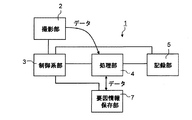
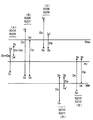
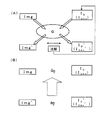
図1には信号処理装置1の構成の概要を示している。信号処理装置1は、人物等の画像を撮影する撮影部2と、その撮影部2を駆動する制御系部3と、撮影部2で撮影された画像を処理する処理部4と、を有している。また、この実施の形態に係る信号処理装置1は、さらに処理部4で処理された画像を記録する記録部5と、画像劣化等を生じさせる変化要因情報のデータを保存する要因情報保存部7を有する。
FIG. 1 shows an outline of the configuration of the
撮影部2は、レンズを有する撮影光学系やレンズを通過した光を電気信号に変換するCCDやC−MOS等の撮影素子を備える部分である。制御系部3は、撮影部2,処理部4,記録部5,および要因情報保存部7等、信号処理装置内の各部を制御するものである。
The photographing
処理部4は、画像処理プロセサで構成されており、ASIC(Application Specific Integrated Circuit)のようなハードウェアで構成されている。そして、処理部4は、後述する変化要因情報のデータの生成法に係る処理および画像の復元処理を実行する。たとえば処理部4は、変化要因情報のデータを生成する過程で原信号を小さくする縮小処理を行う。
The
また、この処理部4には、後述する比較用データを生成する際の元となる画像のデータが保管されることもある。さらに処理部4は、ASICのようなハードウェアとして構成されるのではなく、ソフトウェアで処理する構成としても良い。記録部5は、半導体メモリで構成されているが、ハードディスクドライブ等の磁気記録手段、またはDVD等を使用する光記録手段等を採用しても良い。
Further, the
要因情報保存部7は、本発明の実施の形態に係る変化要因情報のデータの生成法によって生成される変化要因情報のデータまたはそのデータを加工したデータを保存しておく記録部である。そして要因情報保存部7は、そのデータの中枢をなすブレの軌跡(履歴)と、その軌跡上の各点にとどまっていた時間(重み)を記憶する。要因情報保存部7で記録されたデータは、撮影された原画像(劣化等の変化が生じた画像)から元画像(変化する前の画像もしくは本来撮影されるべきであった画像またはそれらの近似画像)への復元処理の際に、処理部4で用いられる。よって、処理部4と要因情報保存部7との間では、相互にデータの受け渡しが可能となっている。
The factor
(変化要因情報のデータの生成)
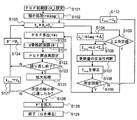
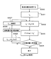
図2に、処理部4が行う本発明の実施の形態に係る変化要因情報のデータの生成法の一例のフローチャートを示す。
(Generation of change factor information data)
FIG. 2 shows a flowchart of an example of a method for generating data of change factor information according to the embodiment of the present invention performed by the
まず、処理部4は、最初の変化要因情報のデータ(PSF)の任意の初期値(P0)を設定する(ステップS101)。ここでは、その初期値を強度分布がガウス分布のデータであるガウシアンディスクとして設定する。
First, the
次に、処理部4は、ステップS101の処理と併行してまたはその処理の前若しくは後に、撮影した原画像のデータ(原信号のデータ)Img’を1/4に縮小する。すなわち、原信号のデータImg’のデータを間引いて25%の容量値とする縮小処理(加工)を行う(ステップS102)。この縮小処理を経たデータである縮小データをSImg’と記す。
Next, the
次に、処理部4は、その縮小データSImg’と同一容量の任意の信号データとしてI0を用い、I0とP0とを重畳積分して比較用のブレたデータI0’を得る(ステップS103)。なお、任意の信号データI0としては、縮小された原画像のデータSImg’が好ましい。
Next, the
次に、処理部4は、SImg’とI0’とを比較し、その差分のデータΔを得る(ステップS104)。その差分のデータΔが所定値以内かを判定し(ステップS105)、所定値以内であればステップS120へ移行し、所定値以内でなければステップS106へ移行する。ステップS106では、その差分のデータΔに係数k(変化要因情報(PSF)に基づいた係数)を乗じたものをI0に配分して、最初の復元データI0+n(今回はI0+1)を得る。ステップS106において、I0に配分する際には、その配分値(更新量)の妥当性を判断する処理を行う(ステップS107)。そして、その妥当性に応じてI0+nを修正する処理を行う(ステップS108)。次に、ステップS109に移行し、この処理が所定回数に達したか否かを判断し、所定回数(たとえば10回)に達したらステップS120へ移行し、所定回数に達していないときはステップS110へ移行する。
Next, the
そして処理部4は、I0+1をI0の代わりに用いて(ステップS110)ステップS103の処理を行い、ステップS103、ステップS104、ステップS105、ステップS106、ステップS107、ステップS108、ステップS109およびステップS110の処理を所定回数(今回は10回)繰り返す。その所定回数に達したか否かの判断をステップS109にて行う。
Then, the
ステップS106の処理は、縮小した原画像のデータSImg’および復元データI0+nを構成する画素のデータの一部または全部を移動(配分)させる処理である。なお、ステップS107およびステップS108の詳細については後述する。 The process of step S106 is a process of moving (distributing) part or all of the pixel data constituting the reduced original image data SImg ′ and the restored data I 0 + n . Details of step S107 and step S108 will be described later.
次に、ステップS109にて所定回数に達したと判断された場合は、処理部4は、PSFを算出する処理を行う(ステップS120)。その処理は、得られた復元データI0+nと縮小された原画像のデータSImg’から新たなPSF(=P)を得る処理である。その処理の具体例は、得られた復元データI0+nと原画像の縮小データSImg’をそれぞれフーリエ変換し、周波数空間での割り算によってPSFの周波数特性を算出し、その周波数特性をフーリエ逆変換することによってPSF(=P)を得る。
Next, when it is determined in step S109 that the predetermined number of times has been reached, the
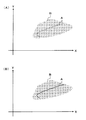
次に、処理部4は、Pのデータの中枢をなすブレの軌跡の部分(骨格部)のデータの値を2倍にして、骨格部を強調する処理を行う(ステップS121)。図3(A)は、現段階の時点で推定されるPSFをX−Y平面上に示したものである。このX−Y平面は、後述する図6に示す信号処理装置1のブレが生じやすいX−Y平面に相当する。PSFは、そのデータの中枢をなすブレの軌跡に相当する部分(骨格部)Aと、その周辺のデータ値の小さな部分B(ボケ等の部分)とからなる。この小さな値となる部分Bは、ボケの部分と考えられる。図3(B)は、Aの部分を強調する処理(ステップS121)を行った後のPSFの状態を示している。Aの骨格部分が若干強調されていることがわかる。この処理に当っては、細線化処理が採用されているが、他の強調方法を採用してもよい。この処理の結果、ステップS120で得られたPのデータは、P’のデータとなる。その後、ステップS106における配分のための移動エネルギーが最小となるようにP’の原点を設定する処理(詳細は後述する)を行う(ステップS122)。
Next, the
次に、処理部4は、P’が妥当なPSFか否かを判断する。具体的には、処理部4は、ステップS120からS122までの処理を3回繰り返したか否かを判断する(ステップS123)。繰り返しの回数、すなわちPSFの算出回数が3回を満たしていなければ(N)、P’のデータをP0の代わりに用いて(ステップS124)、ステップS103からS110までの処理を繰り返し、その後再度ステップS120〜S122を実行する。
Next, the
そして、ステップS123の判断において、PSF算出の回数、すなわち繰り返しの回数が3回を満たしていれば(Y)、処理部4は、得られたP’のデータおよびI0+nのデータを同じ比率で拡大処理する(ステップS125)。この実施の形態では、最後に得られたP’とI0+nを4/3倍する。その拡大処理が予め定められていた縮小率、すなわち、原画像に対する縮小の程度に至ったか否かを判断する(ステップS126)。所定の縮小率に至っていないと判断すると、拡大処理したI0+nのデータをI0のデータの代わりに用い(ステップS127)、拡大処理したP’のデータをP0の代わりに用いる(ステップS124)。一方、原画像のデータを1/3に縮小した新たな縮小画像SImg’を得る。この1/3に縮小した画像は先に4/3倍したデータとは同じサイズの画像となる。そして、処理部4は、新たな各データを用い、ステップS103からS110までの処理を繰り返し、また、ステップS120からS124までの処理を繰り返す。この繰り返しは、ステップS126で所定の縮小率、たとえば原画像データに対して1/3の縮小率に達していると判定されたときは、ステップS128へ移行する。なお、ステップS125では、得られたP’のデータおよびI0+nのデータを同じ比率で拡大処理しているが、拡大処理するのはP’のデータのみとし、拡大処理したI0+nのデータの代わりに任意の信号データを用い、ステップS125を実行しても良い。その任意の信号データは、たとえばSImg’のデータ等である。但し、ステップS125では、本実施の形態のように得られたP’のデータおよびI0+nのデータを同じ比率で拡大処理した方が、復元処理を経たI0+nのデータを用いるため、良質なPSFを生成できる場合がある。
If the number of PSF calculations, that is, the number of repetitions satisfies 3 in the determination of step S123 (Y), the
なお、ステップS125におけるP’のデータの拡大処理は、処理部4が、隣接する信号要素の間にその隣接する信号要素の値の平均値の新たな信号要素のデータを挿入することにより行う。また、I0+nのデータの拡大処理は、処理部4が、隣り合う画素の間に新たな画素を挿入することにより行う。その新たな画素の画素値は、隣り合う画素の画素値を平均した値とする。この拡大処理によって所定の縮小率に達したか否かの判断は、処理部4がステップS126で行う。拡大処理によって所定の縮小率に達したら(Y)、処理部4は、現段階で得られているP’を実寸大に拡大する(ステップS128)。すなわち、現段階で得られているP’は、実寸の1/3のものであるから、処理部4は、現段階で得られているP’を3倍に拡大する。この拡大処理も、処理部4が隣り合う画素の間に新たな画素を挿入することにより行う。その新たな画素の画素値は、隣り合う画素の画素値を平均した値とする。なお、ステップS105,S128の各拡大処理に当っては、上述の補間法以外に、処理部4が、隣り合う画素の間にその隣り合う画素の一の画素の画素値の画素を挿入することにより行う補間法を採用してもよい。
Note that the P ′ data enlargement process in step S125 is performed by the
以上の処理によって、本発明の実施の形態に係る変化要因情報のデータの生成法が終了し(ステップS129)、PSFが生成される。このPSFは、処理部4によって要因情報保存部7に記憶され、信号の復元処理の際に用いられる。以上の過程を経て得られたPSFを「G」と表す。
With the above processing, the method for generating data of change factor information according to the embodiment of the present invention is completed (step S129), and a PSF is generated. The PSF is stored in the factor
(配分値の妥当性を判断する処理)
上述のステップS107で行う、配分値の妥当性を判断する処理について図を用いて説明する。
(Process to determine the appropriateness of the distribution value)
Processing for determining the validity of the distribution value performed in step S107 described above will be described with reference to the drawings.
図4および図5は、図2におけるステップS107およびS108の処理の詳細を説明するための図である。この処理の基本的な考え方は、次の通りである。この処理は、復元データI0+nに対し一括して行うものではなく、復元データI0+nを構成する信号要素毎に行うものである。この点はステップS103,S105およびS106の信号(画像)全体の処理とは大きく異なる。まず、P0によって一つの信号要素となる一つの画素が影響を受ける範囲の複数の画素のうち、更新によって画素値の変化が大きくなるものがある場合は、その複数の画素の範囲にエッジとなる部分が存すると考える。そのエッジとなる部分は、対応する部分の差分のデータΔに基づく更新量が適切な量となり難い。なぜならば、エッジ部分を跨ぐ2つの画素の画素値は、その違いが大きすぎるため、一方の画素から他方の画素へとエッジ部分を越えて画素値を配分しても、その配分は適切なものとはなりにくいためである。そこで、更新によって画素値の変化が周囲に比べ不自然に大きくなる画素については、更新量の絶対値を小さくすることで、エッジ近傍への更新量を適切なものに近づける。 4 and 5 are diagrams for explaining the details of the processing in steps S107 and S108 in FIG. The basic concept of this processing is as follows. This process is not performed for the restored data I 0 + n in a lump, but for each signal element constituting the restored data I 0 + n . This point is greatly different from the processing of the entire signal (image) in steps S103, S105, and S106. First, when there is a pixel whose change in pixel value is greatly increased by updating among a plurality of pixels in a range in which one pixel serving as one signal element is affected by P 0 , an edge and an edge are included in the range of the plurality of pixels. I think that there will be a part. For the portion serving as the edge, the update amount based on the difference data Δ of the corresponding portion is unlikely to be an appropriate amount. This is because the difference between the pixel values of two pixels straddling the edge part is too large, so even if the pixel value is distributed from one pixel to the other pixel across the edge part, the distribution is appropriate. This is because it is difficult to. Therefore, for pixels whose change in pixel value is unnaturally larger than the surroundings due to the update, the update amount in the vicinity of the edge is brought close to an appropriate value by reducing the absolute value of the update amount.
そのためには、まず、所定の差分のデータΔからある画素の更新量(Dc)を算出する(ステップS201)。そして、変化要因情報Gによって一つの画素が影響を及ぼす範囲の複数の画素(一部の信号要素)およびその一つの画素との集合を参照し、その参照する各々の画素の更新前の画素値(=Ib)の最小値(=Min)、最大値(=Max)および平均値(=Av)を算出する(ステップS202)。なお、この一部の画素(参照する画素)は、単純に隣接する複数の画素、あるいは所定の画素を中心としてそこから所定の距離に含まれる複数の画素としても良い。その所定の距離は、たとえば変化要因情報のデータGを利用して決定される。 For this purpose, first, an update amount (Dc) of a certain pixel is calculated from predetermined difference data Δ (step S201). Then, reference is made to a set of a plurality of pixels (a part of signal elements) in the range in which one pixel is affected by the change factor information G and the one pixel, and the pixel value before the update of each pixel to be referred to A minimum value (= Min), a maximum value (= Max), and an average value (= Av) of (= Ib) are calculated (step S202). The partial pixels (reference pixels) may be simply a plurality of adjacent pixels or a plurality of pixels included in a predetermined distance from a predetermined pixel as a center. The predetermined distance is determined using data G of change factor information, for example.
次に、参照する画素のうちの一つの画素(=一つの信号要素)の更新後の画素値となるデータ(=Ia)を算出する(ステップS203)。この更新後の画素値Iaは、ある画素に対応した差分のデータδから算出した各画素毎の更新量(Dc)を用いて更新した場合の各画素毎の画素値であり、次の(1)式によって導かれる。
Ia=Ib+Dc ……(1)
Next, data (= Ia) that is the updated pixel value of one pixel (= one signal element) among the referenced pixels is calculated (step S203). This updated pixel value Ia is a pixel value for each pixel when updated using the update amount (Dc) for each pixel calculated from the difference data δ corresponding to a certain pixel. ) Guided by the formula.
Ia = Ib + Dc (1)
次に、修正前の更新量(Dc)の妥当性を判断する。まず、復元データを構成する信号要素のデータとなる更新後の画素値Iaが最小値Min以上であり最大値Max以下である場合には(ステップS204の判断が「Y」(=Yes))、その画素は、周囲の画素との画素値のバランスが自然であり、更新量Dcは、修正せずにそのまま修正後の更新量(Dp)とし、修正値Ia’を得る(ステップS205,S214)。なおステップS214は、修正後の更新量Dpによって修正値Ia’を得るステップである。図5の(A)に示す矢印は、ステップS205およびステップS214の処理を経た状態を概略的に表しており、矢印の黒丸は画素の更新前の画素値Ibを示し、三角の矢示はDpによって更新した後の修正値Ia'を示し、矢印の長さは更新量(Dc=Dp)を示している。左側の矢印は、修正前の更新量Dcの値が正の値の場合、右側の矢印は、修正前の更新量Dcの値が負の値の場合についての一例を示している。 Next, the validity of the update amount (Dc) before correction is determined. First, when the updated pixel value Ia, which is signal element data constituting the restored data, is not less than the minimum value Min and not more than the maximum value Max (determination in step S204 is “Y” (= Yes)), The pixel has a natural balance of pixel values with the surrounding pixels, and the update amount Dc is not corrected and is used as the update amount (Dp) after correction, thereby obtaining a correction value Ia ′ (steps S205 and S214). . Step S214 is a step for obtaining a correction value Ia 'by the update amount Dp after correction. The arrow shown in FIG. 5A schematically shows the state after the processing of step S205 and step S214, the black circle of the arrow indicates the pixel value Ib before the pixel update, and the triangular arrow indicates Dp Indicates the corrected value Ia ′ after updating, and the length of the arrow indicates the update amount (Dc = Dp). The left arrow indicates an example when the value of the update amount Dc before correction is a positive value, and the right arrow indicates an example when the value of the update amount Dc before correction is a negative value.
そして、ステップS204の判断が「N」(=No)の場合は、ステップS206へと進む。ここでは、更新後の画素値Iaが最大値Maxを超えてしまっている場合であって更新前の画素値Ibが平均値Av以下である場合には(ステップS206の判断が「Y」(=Yes))、その画素は、周囲の画素との画素値のバランスが不自然であると判断する。そして、更新量Dcは、最大値Maxから更新前の画素値Ibを差し引いた値Dpへと変更される(ステップS207)。この結果、修正値Ia’の画素値は、最大値Maxと等しくなる。図5の(B)に示す矢印は、ステップS207およびステップS214を経た状態を、図5(A)と同様に概略的に表している。左側の矢印は、Dcによって更新した場合のIa、右側の矢印は、Dpによって更新した場合の修正値Ia’を示している。 When the determination in step S204 is “N” (= No), the process proceeds to step S206. Here, when the updated pixel value Ia exceeds the maximum value Max and the updated pixel value Ib is equal to or less than the average value Av (determination in step S206 is “Y” (= Yes)), it is determined that the pixel value balance with the surrounding pixels is unnatural. Then, the update amount Dc is changed to a value Dp obtained by subtracting the pixel value Ib before update from the maximum value Max (step S207). As a result, the pixel value of the correction value Ia ′ becomes equal to the maximum value Max. The arrow shown in FIG. 5B schematically shows the state after step S207 and step S214, as in FIG. The left arrow indicates Ia when updated by Dc, and the right arrow indicates a correction value Ia 'when updated by Dp.
そして、ステップS206の判断が「N」(=No)の場合は、ステップS208へと進む。ここでは、更新後の画素値Iaが最大値Maxを超えてしまっている場合であって更新前の画素値Ibが平均値Avを越える場合には(ステップS208の判断が「Y」(=Yes))、その画素は、周囲の画素との画素値のバランスが不自然であると判断する。その場合、更新量Dcは、以下の(2)式から得られる値Dpへと変更される(ステップS209)。この結果、修正値Ia’の画素値は、更新後の画素値Iaが最大値Maxをプラス側に超えた分の1/4を最大値Maxに加えた値となる。図5の(C)に示す矢印は、ステップS209およびステップS214を経た状態を、図5(B)と同様に概略的に表している。
Dp=0.25(Ia−Max)+(Max−Ib) …(2)
When the determination in step S206 is “N” (= No), the process proceeds to step S208. Here, when the updated pixel value Ia exceeds the maximum value Max and the updated pixel value Ib exceeds the average value Av (the determination in step S208 is “Y” (= Yes). )), It is determined that the pixel value balance with the surrounding pixels is unnatural. In this case, the update amount Dc is changed to a value Dp obtained from the following equation (2) (step S209). As a result, the pixel value of the correction value Ia ′ is a value obtained by adding ¼ of the updated pixel value Ia exceeding the maximum value Max to the plus side to the maximum value Max. The arrow shown in FIG. 5C schematically shows the state after step S209 and step S214, as in FIG. 5B.
Dp = 0.25 (Ia−Max) + (Max−Ib) (2)
そして、ステップS208の判断が「N」(=No)の場合は、ステップS210へと進む。ここでは、更新後の画素値Iaが最小値Min未満であって更新前の画素値Ibが平均値Av以下である場合には(ステップS210の判断が「Y」(=Yes))、その画素は、周囲の画素との画素値のバランスが不自然であると判断する。そして、更新量Dcは、以下の(3)式から得られる値Dpへと変更される(ステップS211)。この結果、修正値Ia’の画素値は、更新後の画素値Iaが最小値Minをマイナス側に超えた分の1/4を最小値Minから引いた値となる。図5の(D)に示す矢印は、ステップS211およびステップS214を経た状態を、図5(B)と同様に概略的に表している。
Dp=−(Ib−Min)−0.25(Min−Ia) …(3)
When the determination in step S208 is “N” (= No), the process proceeds to step S210. Here, when the pixel value Ia after update is less than the minimum value Min and the pixel value Ib before update is equal to or less than the average value Av (the determination in step S210 is “Y” (= Yes)), the pixel Determines that the balance of pixel values with surrounding pixels is unnatural. Then, the update amount Dc is changed to a value Dp obtained from the following equation (3) (step S211). As a result, the pixel value of the correction value Ia ′ is a value obtained by subtracting ¼ of the updated pixel value Ia exceeding the minimum value Min to the minus side from the minimum value Min. The arrow shown in FIG. 5D schematically shows the state after step S211 and step S214, as in FIG. 5B.
Dp = − (Ib−Min) −0.25 (Min−Ia) (3)
そして、ステップS210の判断が「N」(=No)の場合は、更新後の画素値Iaが最小値Min未満であって更新前の画素値Ibが平均値Avを超えている場合となる(ステップS212)。その場合には、その画素は、周囲の画素との画素値のバランスが不自然である。そして、更新量Dcは、最小値Minから更新前の画素値Ibを差し引いた値Dpへと変更される(ステップS213)。この結果、修正値Ia’の画素値は、最小値Minと等しくなる。図5の(E)に示す矢印は、ステップS213およびステップS214を経た状態を、図5(B)と同様に概略的に表している。 If the determination in step S210 is “N” (= No), the updated pixel value Ia is less than the minimum value Min, and the updated pixel value Ib exceeds the average value Av ( Step S212). In that case, the pixel value balance with the surrounding pixels is unnatural. Then, the update amount Dc is changed to a value Dp obtained by subtracting the pixel value Ib before update from the minimum value Min (step S213). As a result, the pixel value of the correction value Ia ′ becomes equal to the minimum value Min. The arrow shown in (E) of FIG. 5 schematically represents the state after step S213 and step S214, as in FIG. 5 (B).
以上のステップS204,S206,S208,S210に示す判断の処理は、所定の基準を満たすか否かを判定する処理となる。なお、このステップS204,S206,S208,S210の判断、およびステップS212の条件を満足するか否かを判断基準としたものの判断の順序は、適宜変更できる。その変更を行ったときも、実際に判断するのは最初から4つめまでである。その4つに該当しなかった場合は、必ず残りの条件に当てはまることとなるため、残りの条件に該当するか否かは、図4におけるステップS212と同様に所定の基準を満たすか否かを判定する処理とはならない。 The determination processing shown in the above steps S204, S206, S208, and S210 is processing for determining whether or not a predetermined standard is satisfied. It should be noted that the order of determination based on the determination in steps S204, S206, S208, and S210 and whether or not the condition in step S212 is satisfied can be changed as appropriate. Even when the change is made, the first to fourth judgment is actually made. If none of the four conditions is met, the remaining conditions will always be met. Therefore, whether the remaining conditions are met is determined by whether or not the predetermined criteria are satisfied as in step S212 in FIG. It is not a judgment process.
このように、得られたDpを修正した更新量とし、修正値Ia’が得られることとなる(ステップS214)。この結果、ある画素が更新される(ステップS215)。そして、全ての画素が更新されたか否かの判断を行う(ステップS216)。その判断が「N」(=No)の場合は、参照する画素を変更して(ステップS217)、変更後の参照する画素(他の一部の信号要素)から所定の基準を求めるためおよび次の画素の修正値Ia’を得るためにステップS202に戻り、ステップS202〜217の処理を繰り返す。この処理では、一つの画素の更新量を修正したら、参照する画素を変更して別の一つの画素の更新量を変更している。そして、ステップS216の判断が「Y」(=Yes)の場合は、全ての画素の修正値Ia’を用いて復元データI0+nを修正する(ステップS218)。以上で図2におけるステップS107,108が終了する。 In this way, the obtained Dp is used as an updated amount, and the corrected value Ia ′ is obtained (step S214). As a result, a certain pixel is updated (step S215). Then, it is determined whether or not all the pixels have been updated (step S216). If the determination is “N” (= No), the pixel to be referred to is changed (step S217), and a predetermined standard is obtained from the changed reference pixel (other signal elements) and In order to obtain the correction value Ia ′ of the pixel, the process returns to step S202, and the processes of steps S202 to 217 are repeated. In this process, when the update amount of one pixel is corrected, the reference pixel is changed to change the update amount of another pixel. When the determination in step S216 is “Y” (= Yes), the restoration data I 0 + n is corrected using the correction value Ia ′ of all pixels (step S218). The steps S107 and 108 in FIG.
(P’の原点を設定する処理)
上述の図2におけるステップS122で行う、P’の原点を設定する処理について図を用いて説明する。
(Process to set the origin of P ')
The process for setting the origin of P ′ performed in step S122 in FIG. 2 will be described with reference to the drawings.
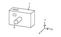
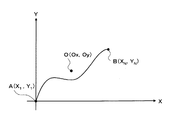
要因情報保存部7には、上述の図2におけるステップS122の段階のデータが保存される。すなわち、図6に示す信号処理装置1のブレと推定できるデータが要因情報保存部7に保存される。この図6には、図1に示す信号処理装置1の外観が示されている。この信号処理装置1の図に示すXYZの各方向軸を中心とした回転がブレとなるが、特に現れやすいのはXとYの方向軸回りである。図7に示すブレに関するデータは、図6におけるX−Y平面上における座標データの経時変化のデータである。そのデータは、図7に示すX−Y平面で表されるようなブレの軌跡の情報およびその軌跡上の各位置にどの程度の期間とどまっていたかの情報を含む。図7に示すX−Y平面の始点A(X1,Y1)は、撮影開始位置であり、軌跡の終点B(XN,YN)は、撮影終了位置である。
The factor
ブレによる画像の劣化は、光エネルギーが1点に集中せずに、光エネルギーが図7に示す軌跡A−B上に分散する現象である。よって分散した光エネルギーを1点に集中させることが、原画像を元画像へと復元することとなる。その光エネルギーを集中させる1点は、自由に決定できる。たとえば図4におけるA点、B点、A−Bの軌跡上またはA−Bの軌跡を外れた点に決定できる。 The deterioration of the image due to blurring is a phenomenon in which the light energy is not concentrated on one point but is scattered on the trajectory AB shown in FIG. Therefore, concentrating the dispersed light energy at one point restores the original image to the original image. One point for concentrating the light energy can be freely determined. For example, it can be determined as a point on point A, point B, point AB in FIG. 4 or a point off the point AB.
ここで、分散した光エネルギーを集中させる点を「原点位置」と言うこととし、原点位置は、図7に示すX−Y平面上の点0座標(0x,0y)で表すこととする。また、上述したステップS120で算出したPSFの骨格部をステップS121の処理で強調したデータ(P’)をG(Xn,Yn)で表すこととする。これは、各位置(Xn,Yn)においてどの程度の期間とどまっていたかの情報である「重さ」を示し、(4)式を満たす。(4)式は、光エネルギーを1と正規化して取り扱うことを示す。なお、(Xn,Yn)は、図7に示すX−Y平面上の座標である。

また、分散した光エネルギーを原点位置である点0へ集中させる移動エネルギーをE(0x,0y)で表すこととする。すると分散したエネルギーを原点位置(0x、0y)に集中させる移動エネルギーは、移動距離と重さの関数で表現することができ、たとえば以下の式(5)(n=1,2,・・・N:Nは分散して広がった領域数)で表わすことができる。
![]()
![]()
そして、移動エネルギーE(0x,0y)を最小値とする原点位置(0x,0y)を設定する。この設定は、処理部4で行われる。また、処理部4は、新たに原点位置が設定されたデータを、その設定の前に要因情報保存部7に保存されていたデータに代えて保存する。
また、より移動距離に重きを置く場合は、以下の式(6)を用いることもできる。この(6)式の方が平方根の計算が無く、計算が楽になる利点がある。
さらに、より計算を楽にするためには、以下の式(7)を用いることもできる。
Moreover, when placing more weight on the moving distance, the following equation (6) can also be used. This formula (6) has the advantage that there is no square root calculation and the calculation is easy.
Furthermore, in order to make calculation easier, the following equation (7) can be used.
(信号復元処理)
次に、以上のように構成された本実施の形態に係る信号処理装置1の処理部4の画像復元処理方法(復元手段)の概要を、図8および図9に基づいて説明する。なお、画像復元処理方法は先に説明したステップS102,S103,S104,S105,S106,S107,S108,S110の処理とほぼ同様であり、繰り返し処理となっている。
(Signal restoration processing)
Next, an outline of an image restoration processing method (restoration means) of the
ここで、原画像の元画像への復元処理を実行する時期は、撮影用の電源がオフされている時、処理部4が稼働していない時、処理部4の稼働率が低い時等、原画像を撮影した時期から遅らせた時期とすることができる。その場合には、記録部5に保存された原画像データおよび、要因情報保存部7に保存された、その原画像についての伝達関数等の変化要因情報が、それぞれが関連づけられた状態で長期間に渡り保存される。このように、原画像の復元処理を実行する時期を、原画像を撮影した時期から遅らせる利点は、種々の処理を伴う撮影時の処理部4の負担を軽減できることである。
Here, when the restoration process of the original image to the original image is performed, when the imaging power is turned off, when the
図8中、「I0」は、任意の初期画像であって、処理部4の記録部に予め保存されている画像のデータである。「I0’」は、その初期画像のデータのI0の劣化画像のデータを示し、比較のための比較用データである。「G」は、図2に示す処理で推定された変化要因情報(=劣化要因情報(伝達関数))のデータで、要因情報保存部7に保存されていたものを処理部4が抽出し、処理部4の記録部に保存されるものである。「Img’」は、原画像のデータである。
In FIG. 8, “I 0 ” is an arbitrary initial image and is image data stored in advance in the recording unit of the
「δ」は、原画像データImg’と、比較用データI0’との差分のデータである。「k」は、変化要因情報のデータに基づく配分比である。「I0+n」は、初期画像のデータI0に、差分のデータδを変化要因情報のデータGに基づいて配分して新たに生成した復元画像のデータ(復元データ)である。「Img」は、元画像のデータである。ここで、ImgとImg’の関係は、次の(8)式で表されるものとする。
Img’=Img*G ……(8)
ここで、「*」は、重畳積分を表す演算子である。
“Δ” is difference data between the original image data Img ′ and the comparison data I 0 ′. “K” is an allocation ratio based on the data of the change factor information. “I 0 + n ” is restored image data (restored data) newly generated by allocating the difference data δ to the initial image data I 0 based on the data G of the change factor information. “Img” is data of the original image. Here, the relationship between Img and Img ′ is represented by the following equation (8).
Img ′ = Img * G (8)
Here, “*” is an operator representing a superposition integral.
なお、差分のデータδは、対応する画素の単純な差分でも良い場合もあるが、一般的には、変化要因情報のデータGにより異なり、次の(9)式で表される。
δ=f(Img’,Img,G) …(9)
The difference data δ may be a simple difference between corresponding pixels, but in general, the difference data δ differs depending on the data G of the change factor information, and is expressed by the following equation (9).
δ = f (Img ′, Img, G) (9)
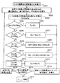
処理部4の処理ルーチンは、まず、分散した光エネルギーを集中させる原点位置を決定する(ステップS300)。この決定は、既に図2に示すステップS122で行っている。よって、この処理の詳細な説明は省略する。そして、任意の画像データI0を用意する(ステップS301)。この初期画像のデータI0としては、劣化している原画像のデータImg’を用いても良く、また、黒ベタ、白ベタ、灰色ベタ、市松模様等どのような画像のデータを用いても良い。ステップS302で、(8)式のImgの代わりに初期画像となる任意の画像のデータI0を入れ、劣化画像である比較用データI0’を求める。次に、原画像データImg’と比較用データI0’とを比較し、差分のデータδを算出する(ステップS303)。
The processing routine of the
そして、差分のデータδの各々の絶対値が所定値未満であるか否かを判断する(ステップS304)。ステップS304で差分のデータδが所定値以上であれば、ステップS305で新たな復元画像のデータ(=復元データ)を生成する処理を行う。すなわち、個々の信号要素が得られた個々の差分のデータδを変化要因情報のデータGに基づいて、任意の画像データI0に配分し、新たな復元データI0+nを生成する。 Then, it is determined whether or not each absolute value of the difference data δ is less than a predetermined value (step S304). If the difference data δ is greater than or equal to the predetermined value in step S304, a process of generating new restored image data (= restored data) is performed in step S305. That is, the individual difference data δ from which individual signal elements are obtained is distributed to arbitrary image data I 0 based on the data G of the change factor information, and new restored data I 0 + n is generated.
そして、復元データI0+nを生成する際に用いる更新量(配分値)の妥当性を判断し(ステップS306)、復元データI0+nを修正する(ステップS307)。このステップS306およびステップS307の処理は、上述した図2に示すステップS106、S107で行う、配分値の妥当性を判断し修正する処理と同様に行う。よって、この処理の詳細な説明は省略する。 Then, the validity of the update amount (distribution value) used when generating the restored data I 0 + n is determined (step S306), and the restored data I 0 + n is corrected (step S307). The processing in step S306 and step S307 is performed in the same manner as the processing for determining and correcting the validity of the distribution value performed in steps S106 and S107 shown in FIG. Therefore, detailed description of this process is omitted.
その後、図8のステップS302〜S307を繰り返す。この繰り返しの最中の復元データI0+nは、処理が行われた途中段階の復元データとなる。ステップS304において、各画素の差分のデータδの各々の絶対値が所定値未満となったら、繰り返し処理を終了する。そして、繰り返し処理を終了した時点での復元データI0+nを元画像のデータImgと推定する。すなわち、各画素の差分のデータδの各々の絶対値の最高値または平均値が所定値より小さくなった場合、比較用データI0+n’の元となった復元データI0+nは元画像のデータImgと非常に近似したものとなることから、その復元データI0+nを元画像のデータImgと推定するのである。なお、記録部5には、初期画像のデータI0、変化要因情報のデータG、を記録しておき、必要により処理部4に渡すようにしても良い。
Thereafter, steps S302 to S307 in FIG. 8 are repeated. The restored data I 0 + n in the middle of this repetition is restored data in the middle of processing. In step S304, when each absolute value of the difference data δ of each pixel becomes less than a predetermined value, the iterative process is terminated. Then, the restored data I 0 + n at the time when the repetitive processing is completed is estimated as the original image data Img. That is, when the maximum value or average value of the absolute values of the difference data δ of each pixel becomes smaller than a predetermined value, the restored data I 0 + n that is the basis of the comparison data I 0 + n ′ is the original image data Img. Therefore, the restored data I 0 + n is estimated as the original image data Img. The initial image data I 0 and the change factor information data G may be recorded in the
上述した繰り返し処理方法(復元手段)の考え方をまとめると以下のようになる。すなわち、この処理方法においては、処理の解を逆問題としては解かず、合理的な解を求める最適化問題として解くのである。逆問題として解く場合、理論上は可能であるが、現実問題としては困難である。 The concept of the above-described iterative processing method (restoring means) is summarized as follows. That is, in this processing method, the processing solution is not solved as an inverse problem, but is solved as an optimization problem for obtaining a rational solution. When solving as an inverse problem, it is theoretically possible, but it is difficult as a real problem.
最適化問題として解く場合において、本実施の形態では、次のような条件を前提としている。
すなわち、
(1)入力に対する出力は、一意に決まる。
(2)出力が同じであれば、入力は同じである。
(3)出力が同じになるように、入力を更新し、その更新量を妥当な値に修正しながら反復処理することにより、解を収束させていく。
In the case of solving as an optimization problem, the present embodiment assumes the following conditions.
That is,
(1) The output corresponding to the input is uniquely determined.
(2) If the output is the same, the input is the same.
(3) The input is updated so that the outputs are the same, and the solution is converged by performing iterative processing while correcting the update amount to an appropriate value.
このことを換言すれば、図9(A)(B)に示すように、原画像のデータImg’と近似である比較用データI0’(I0+n’)を生成できれば、その生成の元データとなる初期画像のデータI0または復元データI0+nは、元画像のデータImgに近似したものとなる。 In other words, as shown in FIGS. 9A and 9B, if comparison data I 0 ′ (I 0 + n ′) that is approximate to the original image data Img ′ can be generated, the original data of the generation is generated. The initial image data I 0 or the restored data I 0 + n is approximate to the original image data Img.
なお、この実施の形態では、差分のデータδの判定基準となる値は、各データを8ビット(0〜255)で表した場合に、この実施の形態では「6」としている。すなわち、6より小さい、つまり5以下の時は、処理を終了している。 In this embodiment, the value that is the determination criterion for the difference data δ is “6” in this embodiment when each data is represented by 8 bits (0 to 255). That is, when it is less than 6, that is, 5 or less, the processing is finished.
次に、図8に示す手ブレの復元処理方法(ステップS302,S303,S304,S305,S306,S307の反復処理(復元手段))の詳細を、図10,図11,図12,図13,図14,図15,図16および図17に基づいて説明する。 Next, details of the camera shake restoration processing method (repetitive processing (restoration means) of steps S302, S303, S304, S305, S306, and S307) shown in FIG. 8 will be described in detail with reference to FIG. 10, FIG. 11, FIG. This will be described with reference to FIGS. 14, 15, 16 and 17. FIG.
(手ブレの復元アルゴリズム)
手ブレが無いとき、所定の画素に対応する光エネルギーは、露光時間中、その画素に集中する。また、手ブレがある場合、光エネルギーは、露光時間中にブレた画素に分散する。さらに、露光時間中のブレがわかれば、露光時間中のエネルギーの分散の仕方がわかるため、ブレた画像からブレの無い画像を作ることが可能となる。
(Image restoration algorithm)
When there is no camera shake, the light energy corresponding to a given pixel is concentrated on that pixel during the exposure time. In addition, when there is a camera shake, the light energy is distributed to the blurred pixels during the exposure time. Further, if the blur during the exposure time is known, the manner in which the energy is dispersed during the exposure time can be understood, so that it is possible to create a blur-free image from the blurred image.
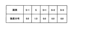
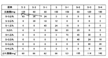
以下、簡単のため、横一次元で説明する。画素を左から順にS−1,S,S+1,S+2,S+3,・・・,とし、ある画素Sに注目する。ブレが無いとき、露光時間中のエネルギーは、その画素に集中するため、エネルギーの集中度は「1.0」である。この状態を図10に示す。このときの撮影結果を、図11の表に示す。図11に示すものが、劣化しなかった場合の正しい画像データImgとなる。なお、各データは、8ビット(0〜255)のデータで表している。 Hereinafter, for the sake of simplicity, the description will be made in one horizontal dimension. Let the pixels be S-1, S, S + 1, S + 2, S + 3,... In order from the left, and pay attention to a certain pixel S. When there is no blur, the energy during the exposure time is concentrated on the pixel, so the energy concentration is “1.0”. This state is shown in FIG. The imaging results at this time are shown in the table of FIG. What is shown in FIG. 11 is the correct image data Img when no deterioration occurs. Each data is represented by 8-bit (0 to 255) data.
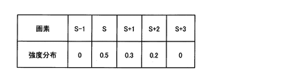
露光時間中にブレがあり、露光時間中の50%の時間はS番目の画素に、30%の時間はS+1番目の画素に、20%の時間はS+2番目の画素にそれぞれブレていたとする。エネルギーの分散の仕方は、図12に示す表のとおりとなる。これが変化要因情報のデータGとなる。 Assume that there is blurring during the exposure time, 50% of the exposure time is blurred to the Sth pixel, 30% of time to the S + 1th pixel, and 20% of time to the S + 2th pixel. The way of energy dispersion is as shown in the table of FIG. This becomes the data G of the change factor information.
露光時間中にブレがあり、露光時間中の50%の時間はS番目の画素に、30%の時間はS+1番目の画素に、20%の時間はS+2番目の画素にそれぞれブレていたとする。エネルギーの分散の仕方は、図12に示す表のとおりとなる。これが変化要因情報のデータGとなる。上述の式(5)における「N」の値は「3」となり、「重み」としての50%、30%、および20%の総和が「1」となる。よって、この変化要因情報G(ここでは、横一次元で考えるため、G(Xn)となる)は、上述の式(4)を満たす。 Assume that there is blurring during the exposure time, 50% of the exposure time is blurred to the Sth pixel, 30% of time to the S + 1th pixel, and 20% of time to the S + 2th pixel. The way of energy dispersion is as shown in the table of FIG. This becomes the data G of the change factor information. The value of “N” in the above formula (5) is “3”, and the sum of 50%, 30%, and 20% as “weight” is “1”. Therefore, the change factor information G (here, G (Xn) is considered in a one-dimensional horizontal direction) satisfies the above-described formula (4).
この図12および式(5)に基づいて、移動エネルギーE(0x,0y)を算出する。ここでは、横一次元で考えるため、移動エネルギーは、E(0x)となる。また、移動距離は、画素一つ分の移動距離を「1」として計算する。すると、分散した光エネルギーを画素「S」に集中させる場合の移動エネルギーは、E(0x)は、以下のように計算され、求められる。
(1×0)+(0×0.5)+(1×0.3)+(2×0.2)=0.7
Based on this FIG. 12 and Formula (5), the movement energy E (0x, 0y) is calculated. Here, since it is considered in one horizontal dimension, the movement energy is E (0x). Also, the movement distance is calculated by assuming that the movement distance for one pixel is “1”. Then, the movement energy in the case where the dispersed light energy is concentrated on the pixel “S” is obtained by calculating E (0x) as follows.
(1 × 0) + (0 × 0.5) + (1 × 0.3) + (2 × 0.2) = 0.7
同様に、分散した光エネルギーを画素「S+1」に集中させる場合の移動エネルギーは、E(0x)は、以下のように計算され、求められる。
(1×0.5)+(0×0.3)+(1×0.2)=0.7
Similarly, E (0x) is calculated and calculated as follows when the dispersed light energy is concentrated on the pixel “S + 1”.
(1 × 0.5) + (0 × 0.3) + (1 × 0.2) = 0.7
同様に、分散した光エネルギーを画素「S+2」に集中させる場合の移動エネルギーは、E(0x)は、以下のように計算され、求められる。
(2×0.5)+(1×0.3)+(0×0.2)=1.3
Similarly, E (0x) is calculated and obtained as follows when the dispersed light energy is concentrated on the pixel “S + 2”.
(2 × 0.5) + (1 × 0.3) + (0 × 0.2) = 1.3
以上の結果から、図12の場合は、分散した光エネルギーを画素「S」または「S1」に集中させることで、移動エネルギーを最小値の「0.7」とすることができる。また、図12の代わりに「S=0.45」「S+1=0.3」「S+2=0.25」の場合は、画素「S+1」への移動エネルギーの総和が最も小さくなる。すなわち、画素「S」への移動は「0.8」となり画素「S+1」への移動は「0.7」となり、画素「S+2」への移動が「1.2」となるためである。以下、分散した光エネルギーを移動エネルギーが最も小さい位置、すなわち上述の図12の例で画素「S」へと、集中させる場合の繰り返し処理の詳細について説明する。 From the above results, in the case of FIG. 12, the kinetic energy can be set to the minimum value “0.7” by concentrating the dispersed light energy on the pixel “S” or “S1”. Further, when “S = 0.45”, “S + 1 = 0.3”, and “S + 2 = 0.25” instead of FIG. 12, the sum of the kinetic energy to the pixel “S + 1” is the smallest. That is, the movement to the pixel “S” is “0.8”, the movement to the pixel “S + 1” is “0.7”, and the movement to the pixel “S + 2” is “1.2”. Hereinafter, the details of the iterative process when the dispersed light energy is concentrated on the position where the moving energy is the smallest, that is, on the pixel “S” in the above-described example of FIG. 12 will be described.
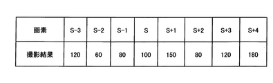
ブレは、全ての画素で一様であり、線形問題として把握される。そして、上ブレ(縦ブレ)が無いとすると、ブレの状況は、図13に示す表のとおりとなる。図13中の「ブレ画像」として示されるデータが、劣化している原画像のデータImg’となる。具体的には、たとえば「S−3」の画素の「120」は、ブレ情報である変化要因情報のデータGの「0.5」「0.3」「0.2」の配分比に従い、「S−3」の画素に「60」、「S−2]の画素に「36」、「S−1」の画素に「24」というように分散する。同様に、「S−2」の画素データである「60」は、「S−2」に「30」、「S−1」に「18」、「S」に「12」として分散する。この劣化している原画像データImg’と、図12に示す変化要因情報のデータGから元画像データImgを算出することとなる。 Blur is uniform for all pixels and is understood as a linear problem. If there is no upper blur (vertical blur), the blur situation is as shown in the table of FIG. The data shown as “blurred image” in FIG. 13 becomes the degraded original image data Img ′. Specifically, for example, “120” of the pixel “S-3” is in accordance with the distribution ratio of “0.5”, “0.3”, “0.2” of the data G of the change factor information that is blur information, Dispersed in such a manner that “60” is distributed to the “S-3” pixel, “36” is distributed to the “S-2” pixel, and “24” is distributed to the “S-1” pixel. Similarly, “60” which is the pixel data of “S-2” is distributed as “30” in “S-2”, “18” in “S-1”, and “12” in “S”. The original image data Img is calculated from the deteriorated original image data Img ′ and the change factor information data G shown in FIG.
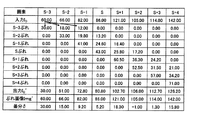
ステップS301に示す任意の画像データI0としては、どのようなものでも採用できるが、この説明に当たっては、原画像データImg’を用いる。すなわち、I0=Img’として処理を開始する。図14の表中に「入力」とされたものが初期画像のデータI0に相当する。このデータI0すなわちImg’と、ステップS302で変化要因情報のデータGとを重畳積分する。すなわち、たとえば、初期画像のデータI0の「S−3」の画素の「60」は、S−3の画素に「30」が、「S−2」の画素に「18」が、「S−1」の画素に「12」がそれぞれ割り振られる。他の画素についても同様に配分され、「出力I0’」として示される比較用データI0’が生成される。このため、ステップS303の差分のデータδは、図14の最下欄に示すようになる。この差分のデータδの絶対値の最高値が所定値、たとえば10未満となるか判断する(ステップS304)、この例では「S−3」の画素の差分のデータδが30であり、ステップS304でNo(=N)となり、ステップS305へ移行する。 Any arbitrary image data I 0 shown in step S301 can be adopted, but in this description, original image data Img ′ is used. That is, the process starts with I 0 = Img ′. In the table of FIG. 14, “input” corresponds to the initial image data I 0 . This data I 0, that is, Img ′ is superposed and integrated with the change factor information data G in step S302. That is, for example, “60” of the “S-3” pixel of the initial image data I 0 is “30” for the S-3 pixel, “18” for the “S-2” pixel, “12” is assigned to each pixel of “−1”. The other pixels are similarly distributed, and comparison data I 0 ′ shown as “output I 0 ′” is generated. Therefore, the difference data δ in step S303 is as shown in the bottom column of FIG. It is determined whether the maximum absolute value of the difference data δ is a predetermined value, for example, less than 10 (step S304). In this example, the difference data δ of the pixel “S-3” is 30, and step S304 is performed. No (= N) and the process proceeds to step S305.
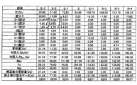
差分のデータδの配分は、図15に示すように、たとえば「S−3」の画素データ「30」に、自分の所(=「S−3」の画素)の配分比である0.5をかけた「15」を「S−3」の画素に配分し、また「S−2」の画素のデータ「15」にその「S−2」の画素にきているはずの配分比である0.3をかけた「4.5」を配分し、さらに、「S−1」の画素のデータ「9.2」に、その「S−1」の画素にきているはずの配分比である0.2をかけた「1.84」を配分する。「S−3」の画素に配分された総量(各画素毎の更新量Dc)は、「21.34」となり、この値を図4における初期画像のデータI0である、図4におけるIb(ここでは原画像データImg’を使用)にプラスして、図8における復元データI0+1である、図4における更新後の画素値Iaが算出される。この例では、図15に示すように更新後の画素値Iaは「81.34」となる。このように、差分のデータδを変化要因情報のデータGを使用して、任意の画像のデータI0に配分して、図15中の「次回入力」として示される復元データI0+nを生成する。この場合、第1回目であるため、図15では、I0+1と表している。 As shown in FIG. 15, the distribution of the difference data δ is 0.5, which is the distribution ratio of the pixel data “30” of “S-3” to the own location (= the pixel of “S-3”), for example. “15” multiplied by “S-3” is distributed to the pixel of “S-3”, and the data “15” of the pixel of “S-2” is allocated to the pixel of “S-2”. “4.5” multiplied by 0.3 is allocated, and further, the data “9.2” of the pixel “S-1” is allocated to the pixel “S-1” by the distribution ratio. “1.84” multiplied by a certain 0.2 is allocated. The total amount (update amount Dc for each pixel) allocated to the pixels of “S-3” is “21.34”, and this value is the data I 0 of the initial image in FIG. Here, the updated pixel value Ia in FIG. 4 which is the restored data I 0 + 1 in FIG. 8 is calculated in addition to the original image data Img ′. In this example, as shown in FIG. 15, the updated pixel value Ia is “81.34”. In this way, the difference data δ is distributed to the arbitrary image data I 0 using the change factor information data G to generate the restored data I 0 + n shown as “next input” in FIG. . In this case, since this is the first time, it is represented as I 0 + 1 in FIG.
この後、図8におけるステップS306にて更新量の妥当性を判断する。具体的には、この復元データI0+1を修正するために、画素毎の更新後の画素値(=Ia)を算出する。この算出は、上述の通り(1)式による。そこで、差分のデータδを各画素に配分する。そして、図15に示すように、各画素ごとに、参照する各々の画素の更新前の画素値(=Ib)の最小値(=Min)、最大値(=Max)および平均値(=Av)を算出する(図4におけるステップS202)。たとえば画素「S−3」は、画素「S−3」、画素「S−2」および画素「S−1」を参照している。よって、図15に示すように、画素「S−3」、画素「S−2」および画素「S−1」の最小値(=Min)、最大値(=Max)および平均値(=Av)を算出する。図に示す例では、画素「S−3」に関しては、最大値が画素「S−1」に「82.00」で、最小値が画素「S−3」の「66.00」となり、平均値は、画素「S−3」「S−2」「S−1」の各値の合計を3で割った値で「69.33」となる。画素「S−2」〜「S+4」についても同様の算出を行う。 Thereafter, the validity of the update amount is determined in step S306 in FIG. Specifically, in order to correct the restored data I 0 + 1 , an updated pixel value (= Ia) for each pixel is calculated. This calculation is based on equation (1) as described above. Therefore, the difference data δ is distributed to each pixel. Then, as shown in FIG. 15, for each pixel, the minimum value (= Min), maximum value (= Max), and average value (= Av) of the pixel value (= Ib) before the update of each pixel to be referred to Is calculated (step S202 in FIG. 4). For example, the pixel “S-3” refers to the pixel “S-3”, the pixel “S-2”, and the pixel “S-1”. Therefore, as shown in FIG. 15, the minimum value (= Min), the maximum value (= Max), and the average value (= Av) of the pixel “S-3”, the pixel “S-2”, and the pixel “S-1”. Is calculated. In the example shown in the figure, regarding the pixel “S-3”, the maximum value is “82.00” in the pixel “S-1”, the minimum value is “66.00” in the pixel “S-3”, and the average The value is “69.33”, which is a value obtained by dividing the sum of the values of the pixels “S-3”, “S-2”, and “S-1” by 3. The same calculation is performed for the pixels “S−2” to “S + 4”.
そして、IaおよびIbが図4におけるステップS204,S206,S208,S210およびS212のいずれかの条件を満足するのかを判定する。たとえば画素「S−3」のIaは、「Min(60.00)≦Ia(81.34)≦Max(82.00)」の条件を満足するため、図4におけるステップS204の条件を満足する。よって、図15に示すようにステップS205の処理を行い、Dcである更新量「21.34」をそのまま修正後の更新量Dpとして用い、修正値Ia’は、修正前のIaと等しい「81.34」となる。「S−2」〜「S」、「S+2」および「S+3」の更新後の画素値Iaについても同様の修正を行う。この修正値Ia’が復元データI0+nの修正値となる。 Then, it is determined whether Ia and Ib satisfy any of the conditions in steps S204, S206, S208, S210, and S212 in FIG. For example, Ia of the pixel “S-3” satisfies the condition of “Min (60.00) ≦ Ia (81.34) ≦ Max (82.00)”, and therefore satisfies the condition of step S204 in FIG. . Therefore, the process of step S205 is performed as shown in FIG. 15, and the update amount “21.34” as Dc is used as it is as the update amount Dp after correction, and the correction value Ia ′ is equal to “81 before correction” “81 .34 ". The same correction is performed for the updated pixel values Ia of “S−2” to “S”, “S + 2”, and “S + 3”. This correction value Ia ′ becomes the correction value of the restored data I 0 + n .
たとえば画素「S+1」では、ステップS204、S206の条件を満足せず、ステップS208に移行する。そして、「Ib(121.00)>Av(113.33)」であり、「Ia(130.11)>Max(121.00)」の条件を満足するため、図4におけるステップS208の条件を満足することになる。よって、図15に示すようにステップS209の処理を行い、「2.28」を修正後の更新量Dpとして用い、修正値Ia’は「123.28」となる。画素「S+4」のIaについても同様の修正を行う。このIa’が復元データI0+nの修正値となる。 For example, in the pixel “S + 1”, the conditions of steps S204 and S206 are not satisfied, and the process proceeds to step S208. In order to satisfy “Ib (121.00)> Av (113.33)” and satisfy the condition “Ia (130.11)> Max (121.00)”, the condition of step S208 in FIG. You will be satisfied. Accordingly, the process of step S209 is performed as shown in FIG. 15, and “2.28” is used as the updated amount Dp after correction, and the correction value Ia ′ is “123.28”. The same correction is performed for Ia of the pixel “S + 4”. This Ia ′ becomes a correction value of the restored data I 0 + n .
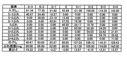
図16に示すように、この修正された復元データI0+1(Ia')がステップS302の新たな入力画像のデータ(=初期画像のデータI0に代わるもの)になり、ステップS302が実行され、ステップS303へと移行し、新しい差分のデータδを得る。その差分のデータδの大きさをステップS304で判断し、所定値より大きい場合、ステップS305で新しい差分のデータδを前回の修正された復元データI0+1に配分し、新しい復元データI0+2を生成することとなるが、その際に、図15の説明と同様にして新しい復元データI0+2を修正する(図17参照)。たとえば、画素「S−3」、「S」および「S+3」の更新後の画素値Iaについては、上述の図15における画素「S−3」と同様の修正を行う。すなわち、更新後の画素値Iaがそのまま修正値Ia’となる。 As shown in FIG. 16, the corrected restored data I 0 + 1 (Ia ′) becomes the new input image data (= replaces the initial image data I 0 ) in step S302, and step S302 is executed. The process proceeds to step S303 to obtain new difference data δ. The size of the difference data δ is determined in step S304. If the difference data δ is larger than the predetermined value, the new difference data δ is distributed to the previously modified restored data I 0 + 1 in step S305 to generate new restored data I 0 + 2 . In this case, the new restoration data I 0 + 2 is corrected in the same manner as described in FIG. 15 (see FIG. 17). For example, the updated pixel value Ia of the pixels “S-3”, “S”, and “S + 3” is corrected in the same manner as the pixel “S-3” in FIG. That is, the updated pixel value Ia becomes the corrected value Ia ′ as it is.
また、たとえば画素「S+1」では、ステップS204,S206の条件を、満足せず、ステップS208に移行する。そして「Ib(121.00)>Av(116.15)」であり、「Ia(125.43)>Max(121.00)」の条件を満足するため、図4におけるステップS208の条件を満足することとなる。よって、図17に示すようにステップS209の処理を行い、上述の(2)式による値「1.106」を修正後の更新量Dpとして用い、修正値Ia’は「122.11」となる。画素「S+4」の更新後の画素値Iaについても同様の修正を行う。この修正値Ia’が復元データI0+nの修正値となる。 For example, in the pixel “S + 1”, the conditions in steps S204 and S206 are not satisfied, and the process proceeds to step S208. Then, “Ib (121.00)> Av (116.15)” and the condition “Ia (125.43)> Max (121.00)” is satisfied, and therefore the condition of step S208 in FIG. 4 is satisfied. Will be. Therefore, the process of step S209 is performed as shown in FIG. 17, and the correction value Ia ′ is “122.11” using the value “1.16” according to the above-described equation (2) as the update amount Dp after correction. . The same correction is performed on the updated pixel value Ia of the pixel “S + 4”. This correction value Ia ′ becomes the correction value of the restored data I 0 + n .
また、たとえば画素「S−2」では、ステップS204,S206,S208の条件を、満足せず、ステップS210に移行する。そして「Ib(77.30)≦Av(87.67)」であり、「Ia(76.97)<Min(77.30)」の条件を満足するため、図4におけるステップS210の条件を満足することとなる。よって、図17に示すようにステップS211の処理を行い、上述の(3)式による値「−0.082」を修正後の更新量Dpとして用い、修正値Ia’は「77.22」となる。画素「S−1」および「S+2」の更新後の画素値Iaについても同様の修正を行う。この修正値Ia’が復元データI0+nの修正値となる。 For example, in the pixel “S-2”, the conditions of steps S204, S206, and S208 are not satisfied, and the process proceeds to step S210. Then, “Ib (77.30) ≦ Av (87.67)” is satisfied, and the condition “Ia (76.97) <Min (77.30)” is satisfied, so the condition of step S210 in FIG. 4 is satisfied. Will be. Therefore, as shown in FIG. 17, the process of step S211 is performed, and the value “−0.082” according to the above equation (3) is used as the updated amount Dp after correction, and the correction value Ia ′ is “77.22”. Become. The same correction is performed on the updated pixel value Ia of the pixels “S−1” and “S + 2”. This correction value Ia ′ becomes the correction value of the restored data I 0 + n .
その後、修正された復元データI0+2を用いてステップS302を遂行することにより、修正された復元データI0+2から新しい比較用データI0+2 ’が生成される。このように、ステップS302,S303が実行された後、ステップS304へ行き、そこでの判断によりステップS305へ移行する。このような処理を繰り返す。 Thereafter, by performing the step S302 by using the restored data I 0 + 2 that are fixed, a new comparison data I 0 + 2 'from the restored data I 0 + 2 that are fixed are generated. As described above, after steps S302 and S303 are executed, the process proceeds to step S304, and the process proceeds to step S305 based on the determination. Such a process is repeated.
(本実施の形態によって得られる主な効果)
本実施の形態に係る変化要因情報の生成法の処理(図2)を実行することによって、変化要因情報のデータ(PSF)が未知であっても妥当なPSFを生成でき、実用的な信号復元が可能となる。よって、ブレ等を機械的に測定する速度センサまたは加速度センサをカメラ等の信号処理装置1の構成要素から省略することができる。また、この処理の際に、処理部4が、縮小処理(ステップS102)をすることによって、変化の大きさも縮小されることから、PSFを推定し易くなり、妥当なPSFが生成される。また、この処理の際に、処理部4が、拡大処理(ステップS125)を拡大率を徐々に大きくして繰り返し行うことによって、縮小処理を行って得た良質なPSFに基づいて大きなPSFの推定をすることができる。また、この処理の際に、処理部4が、配分値の妥当性を判断し修正する処理(ステップS107、S108)をすることによって、配分による極端なデータの値の変化を抑制でき、より妥当なPSFが生成される。また、この処理の際に、処理部4が、P’の原点を再設定する処理をすることによって、配分による極端なデータの値の変化を抑制でき、より妥当なPSFが生成される。また、この処理の際に、処理部4が、縮小処理(ステップS102)を実行することによって、変化の大きさも縮小されることから、PSFを推定し易くなり、より妥当なPSFが生成される。
(Main effects obtained by this embodiment)
By executing the process of the change factor information generation method according to the present embodiment (FIG. 2), a valid PSF can be generated even if the data (PSF) of the change factor information is unknown, and practical signal restoration is possible. Is possible. Therefore, a speed sensor or an acceleration sensor that mechanically measures blur or the like can be omitted from the components of the
また、この処理の際に、処理部4が、PSFの骨格部の強調をする処理(ステップS121)を行うことによって、ブレに相当する変化の推定に重きを置くPSFを生成できる。また、この処理の際に、処理部4が、PSF初期値をガウシアンディスクに設定することで(ステップS101)、変化がどのようなブレまたはボケを含んでいても、良好なPSFの推定をすることができる。
Further, during this process, the
本実施の形態に係る信号処理装置1は、PSFが未知であっても妥当なPSFを生成でき、実用的な信号復元が可能である。よって、ブレ等を機械的に測定する速度センサまたは加速度センサをカメラ等は、信号処理装置1の構成要素から省略することができる。また、変化要因情報の生成処理の際に、縮小処理(ステップS102)をすることによって、変化の大きさも縮小されることから、PSFを推定し易くなり、妥当なPSFに基づいた実用的な信号復元ができる。また、変化要因情報の生成処理の際に、処理部4が、拡大処理(ステップS125)を拡大率を徐々に大きくして繰り返し行うことによって、縮小処理を行って得た良質なPSFに基づいて大きなPSFの推定をすることができ、そのPSFに基づいた実用的な信号復元ができる。
The
また、信号処理装置1は、図8に示すステップS302〜ステップS307を繰り返すことで、差分のデータδが徐々に小さくなっていき、所定値より小さくなると、ブレていない元画像データImgが得られる。また、このとき、修正処理(図4,図5)を行っているため、得られる元画像データImgと推定される画像データは、リンギングの発生が軽減され、画像の復元状態が良好なものとなる。また、修正処理(図4,図5)によって、復元データを構成する信号要素のデータのうち、不自然と思われるものを修正し、画素値の大きな変化を抑制しているため、仮に図2に示す処理によって推定される変化要因情報のデータGが信頼性の低いものであったとしても、妥当な画像の復元が可能となる。
Further, the
(他の形態)
以上、本実施の形態における変化要因情報の生成法および信号処理装置1について説明したが、本発明の要旨を逸脱しない限り種々変更実施可能である。たとえば、変化要因情報の生成法においては、処理部4が、図2に示すステップS103からS108の処理を2回以上繰り返しているが、1回のみとすることができる。さらに、処理部4が、配分値の妥当性を判断し修正する処理(ステップS107、S108)、P’の原点を再設定する処理(ステップS122)、拡大処理(ステップS125)、最終的に初期の画像データ用のPSFのデータと同じ大きさのデータとする拡大処理(ステップS128)およびPSFの骨格部の強調をする処理(ステップS121)の全部または一部は、省略できる。さらに、PSFの初期値は、ガウシアンディスクに設定(ステップS101)せず、任意の値を設定できる。
(Other forms)
As described above, the generation method of the change factor information and the
また、たとえば信号処理装置1における信号復元処理には、図8に示す処理を採用しているが、他の処理、たとえばウィナーフィルターを用いる処理等を採用できる。また、図8に示す処理を採用する場合でも、原点位置を設定する処理(ステップS300)および更新量の妥当性を判断し修正する処理(ステップS306、S307)の双方または一方は、省略することができる。さらに更新量の妥当性を判断し修正する処理(ステップS306、S307)を採用する場合でも、復元データI0+nを修正する方法は、図4および図5に示す方法に限定されない。特に図4に示すステップS204,S206,S208,S210およびS212における場合分け、ステップS205,S207,S209,S211およびS213における差分のデータδを修正する方法は、それぞれ適宜変更することができる。
For example, the signal restoration process in the
また、処理部4が、図2に示すステップS103からS108の処理を10回繰り返すこととしており、また、ステップS123において、ステップS103からS122までを繰り返すこととしているが、処理部4の処理速度の状況等によってそれらの回数を増減できる。また、信号処理装置1のユーザがそれらの回数を任意に設定できることとしても良い。さらに、縮小処理(ステップS102)および拡大処理(ステップS125)の画像の大きさの比率、拡大処理(ステップS125)の画像の大きさの比率の変更回数は、復元画像の画質等によってそれらの回数を増減できる。
In addition, the
また、縮小処理(ステップS102)および拡大処理(ステップS125)における縮小・拡大の仕方は、画素の間引き・隣り合う画素の画素値を平均した値の新たな画素の挿入によって行っている。しかし、他の手段、たとえば隣接する複数の画素の平均画素値の画素をその複数の画素の代わりに用いる縮小処理、隣り合う画素の画素値をそのまま新たな画素の画素値としてその新たな画素を挿入することによって拡大処理を行っても良い。さらに、PSFの骨格部の強調をする処理(ステップS121)において、骨格部のデータの値を2倍にしているが、1.5倍、3倍、4倍、または5倍等としても良い。 The reduction / enlargement method in the reduction process (step S102) and the enlargement process (step S125) is performed by thinning out pixels and inserting a new pixel having a value obtained by averaging the pixel values of adjacent pixels. However, other means, for example, a reduction process using a pixel having an average pixel value of a plurality of adjacent pixels instead of the plurality of pixels, a pixel value of an adjacent pixel as it is as a pixel value of a new pixel, and the new pixel You may perform an expansion process by inserting. Further, in the process of enhancing the skeleton part of PSF (step S121), the value of the skeleton part data is doubled, but may be 1.5 times, 3 times, 4 times, 5 times, or the like.
また、処理部4は、最終的に初期画像用のPSFのデータと同じ大きさのデータとする拡大処理(ステップS128)を行っている。しかしこの処理によって初期画像用のPSFのデータと同じ大きさのデータとする必要はなく、初期画像用のPSFのデータと異なる大きさのデータへと拡大処理することができる。
Further, the
また、処理部4は、PSFを算出する処理を行い(ステップS120)、その処理は、得られた復元データI0+nと原画像のデータImg’をそれぞれフーリエ変換し、周波数空間での割り算によってPSFの周波数特性を算出し、その周波数特性をフーリエ逆変換することによってPSF(=P)を得るものである。しかし、他の手段によって、得られる復元データI0+nと原画像のデータImg’から新たなPSF(=P)を得る処理を採用できる。
Further, the
更新量の妥当性を判断し修正する処理(ステップS306、S307)においては、たとえば、参照する画素としては、影響を及ぼす範囲(影響範囲)のもの以外に、その影響範囲を囲む画素一つ分大きくした範囲としたり、修正しようとする画素を中心として所定の距離の範囲としても良い。また、所定の基準としては、参照する画素の最大値、最小値、平均値を利用してのものではなく、最大値と最小値のみを利用し、修正値を最大・最小を超えた分の1/4や1/3の値を最大値や最小値に付加するようにしても良い。また、上限を最大値の1.2倍、下限を最小値の0.8倍とし、その範囲に入れば、修正しないようにしても良い。すなわち、最大値のX倍、最小値のY倍の範囲に更新後の画素値Iaが入れば修正しないようにしても良い。 In the process of determining and correcting the appropriateness of the update amount (steps S306 and S307), for example, as a pixel to be referenced, one pixel surrounding the affected range is included in addition to the affected range (affected range). It may be a large range or a range of a predetermined distance centering on a pixel to be corrected. In addition, as a predetermined standard, the maximum value, minimum value, and average value of the reference pixel are not used, but only the maximum value and the minimum value are used, and the correction value exceeds the maximum / minimum value. You may make it add the value of 1/4 or 1/3 to the maximum value or the minimum value. Further, the upper limit is set to 1.2 times the maximum value and the lower limit is set to 0.8 times the minimum value. That is, if the updated pixel value Ia is in the range of X times the maximum value and Y times the minimum value, the pixel value Ia may not be corrected.
本実施の形態に係る繰り返し処理では、処理部4は、図2におけるステップS105や図8におけるステップS304の一旦得た画像を再度処理するかの判断では、画像を構成する複数の各画素毎の差分のデータΔ、δの絶対値が全て所定値未満または絶対値の平均値が所定値未満であるか否かを判断し、画像全体の処理を行うか判断している。しかし、所定値との比較の対象を、画像を構成する複数の各画素毎の差分のデータとし、各画素毎に繰り返し処理を停止するか否かを判断するようにしたりしても良い。また、所定値との比較対象を、各画素の差分のデータδの総和、もしくは各画素の差分のデータΔ、δの絶対値の総和、または以上の4つのうちの2つ以上とすることができる。たとえば、各画素毎の差分のデータΔ、δの中で零から最も離れた値と、各画素毎の差分のデータδの総和の値とが、別々の基準を共に満たすか否かを判断するようにしても良い。このように、所定値と比較する値を適宜選択することで、原画像の種類、変化の状態または復元処理の状況に応じて、適切な処理を行うことができる。
In the iterative process according to the present embodiment, the
上述の実施の形態では、復元対象を画像データとしている。しかし、これらの復元処理の考え方および手法は、あらゆるデジタルデータの復元処理に適用できる。たとえば、デジタルの音声データの復元等への適用が可能である。その適用の結果、リンギングのように一部に不正確な音声データ等が発生することを効率よく抑制でき、また変化要因情報のデータが不正確であっても、妥当な結果が得られる復元処理が可能となる。 In the above-described embodiment, the restoration target is image data. However, these restoration processing concepts and techniques can be applied to any digital data restoration processing. For example, it can be applied to restoration of digital audio data. As a result of this application, it is possible to efficiently suppress the occurrence of some inaccurate audio data, such as ringing, and even if the data of the change factor information is inaccurate, a restoration process that can obtain reasonable results Is possible.
また、上述の実施の形態では、信号処理装置1を民生用のカメラとしているが、信号処理装置1は、デジタルカメラ等で撮影した画像のデータを図2、図4、図8および図9等に示す処理の一つまたは複数を実行した上で印刷するプリンタ機器としても良い。また、信号処理装置1は、プリンタ機器に対して図2、図4、図8および図9等に示す処理の一つまたは複数を実行させつつ操作するソフトウェアがインストールされたコンピュータ、さらには図2、図4、図8および図9等に示す処理の一つまたは複数を実行するソフトウェアがインストールされたコンピュータ等としても良い。
In the above-described embodiment, the
また、上述した各処理方法は、プログラム化されても良い。また、プログラム化されたものが記憶媒体、たとえばCD、DVD、USBメモリに入れられ、コンピュータによって読みとり可能とされても良い。この場合、信号処理装置1は、その記憶媒体内のプログラム化されたものが信号処理装置1の外部サーバに入れられ、必要によりダウンロードされ、使用されるようにしても良い。この場合、信号処理装置1は、その記憶媒体内のプログラムをダウンロードする通信手段を持つこととなる。
Moreover, each processing method mentioned above may be programmed. Alternatively, the program may be stored in a storage medium, such as a CD, DVD, or USB memory, and read by a computer. In this case, the
図2、図4、図8等に示す復元処理方法においては、処理部4で行った処理をソフトウェアで構成しているが、それぞれ、一部の処理を分担して行うようにした部品からなるハードウェアで構成しても良い。また、変化要因情報のデータGとしては、劣化要因情報のデータのみではなく、単に画像を変化させる情報や、劣化とは逆に、画像を良くする情報を含むものとする。
In the restoration processing method shown in FIG. 2, FIG. 4, FIG. 8, and the like, the processing performed by the
また、処理の反復回数(ステップS109,ステップS123,ステップS304)が信号処理装置1側で自動的にまたは固定的に設定されている場合、その設定された回数をPSFの値(P,P’)や変化要因情報のデータGによって変更するようにしても良い。たとえば、ある画素のデータがブレにより多数の画素に分散している場合は、反復回数を多くし、分散が少ない場合は反復回数を少なくするようにしても良い。
Further, when the number of processing iterations (step S109, step S123, step S304) is set automatically or fixedly on the
さらに、反復処理中に、差分のデータΔ、δが発散してきたり、エネルギーが移動した後の画像データのエネルギーが小さくならず大きくなってきたら、処理を中止させるようにしても良い。発散しているか否かは、たとえば差分のデータΔ、δの平均値を見てその平均値が前回より大きくなったら発散していると判断する方法を採用できる。また、反復処理中に、入力を異常な値に変更しようとしたときには、処理を中止させるようにしても良い。たとえば8ビットの場合、変更されようとする値が255を超える値であるときには、処理を中止させる。また、反復処理中、新たなデータである入力を異常な値に変更しようとしたとき、その値を使用せず、正常な値とするようにしても良い。たとえば、8ビットの0〜255の中で、255を超える値を入力データとしようとした際は、マックスの値である255として処理するようにする。 Furthermore, the processing may be stopped when the difference data Δ, δ diverges during the iterative processing, or when the energy of the image data after the energy has moved does not decrease but increases. For example, a method of determining whether or not the light is diverging can be determined by looking at the average value of the difference data Δ and δ and determining that the average value is larger than the previous value. In addition, during an iterative process, if an input is to be changed to an abnormal value, the process may be stopped. For example, in the case of 8 bits, if the value to be changed is a value exceeding 255, the processing is stopped. Further, during an iterative process, when an input that is new data is to be changed to an abnormal value, the value may not be used but may be set to a normal value. For example, when a value exceeding 255 within the 8-bit range of 0 to 255 is used as input data, it is processed as a maximum value of 255.
また、出力画像となる復元データを生成する際、PSFの値(P,P’)や変化要因情報のデータGによっては、復元させようとする画像の領域外へ出てしまうようなデータが発生する場合がある。このような場合、領域外へはみ出るデータは反対側へ入れる。また、領域外から入ってくるべきデータがある場合は、そのデータは反対側から持ってくるようにするのが好ましい。 In addition, when generating the restoration data to be the output image, depending on the PSF value (P, P ′) and the data G of the change factor information, data that goes out of the area of the image to be restored is generated. There is a case. In such a case, data that protrudes outside the area is input to the opposite side. Also, if there is data that should come from outside the area, it is preferable to bring that data from the opposite side.
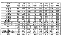
表1に、上述の各処理を実行した復元画像の評価を示す。撮影されブレなどにより劣化したままの画像(Img’)を従来例とする。図2に示した処理によって得られたPSFのデータを用い、図8に示した処理によって信号を復元して得た画像を実施例1とする。図2に示した処理から、表1に示す所定のステップを省略して得られたPSFのデータを用い、図8に示した処理から、表1に示す所定のステップを省略して信号を復元して得た画像を実施例2から12とする。なお、実施例12は、図8の処理に代えて、画像復元処理にウィナーフィルターを用いた画像である。また、比較例1として、図2の処理を行わず、代わりに速度センサによってブレを測定してPSFとしたものの画像についても検討した。さらに、比較例2として、縮小処理(ステップS102)および拡大処理(ステップS125、S126)を省略した画像についても検討した。 Table 1 shows the evaluation of the restored image that has undergone the above-described processes. A conventional example is an image (Img ') that has been photographed and remains degraded due to blurring or the like. An image obtained by restoring the signal by the process shown in FIG. 8 using the PSF data obtained by the process shown in FIG. The PSF data obtained by omitting the predetermined steps shown in Table 1 from the processing shown in FIG. 2 is used, and the signals are restored by omitting the predetermined steps shown in Table 1 from the processing shown in FIG. The images obtained in this way are referred to as Examples 2 to 12. Note that the twelfth embodiment is an image using a Wiener filter for the image restoration process instead of the process of FIG. Further, as Comparative Example 1, the image shown in FIG. 2 without performing the process of FIG. Furthermore, as Comparative Example 2, an image in which the reduction process (step S102) and the enlargement process (steps S125 and S126) are omitted was also examined.
従来例および実施例1から12ならびに比較例の画像について、「ブレの有無」「リンギングの有無」「ボケ(いわゆるピンボケ)の有無」について目視による検査を行った。その検査結果を表1に併せて示す。検査を行った者は、色弱、色盲ではなく視力が両目とも1.0の者である。「有り」と判断する場合は、一見してブレ等があると判断できたものである。「若干有り」と判断する場合は、5秒以下目視して、他の画像と比較しながらブレ等が有ることが判断できるものである。「無い」と判断する場合は、5秒を超えて目視して、他の画像と比較しながらブレ等が無いことが判断できるものである。画像の種類は、風景および人物の2種類である。画像は、市販のカラープリンターで印刷したもので、印刷条件による画像への影響を排除して印刷したものである。 The images of the conventional example, Examples 1 to 12 and the comparative example were visually inspected for “presence / absence of blurring”, “presence / absence of ringing”, and “presence / absence of blur (so-called out-of-focus)”. The test results are also shown in Table 1. Those who have been examined are those who have 1.0 eyesight in both eyes, not color weakness or color blindness. When it is judged as “present”, it can be judged at first glance that there is a blur or the like. When it is determined that “slightly exists”, it can be determined that there is a blur or the like while visually comparing with other images for 5 seconds or less. When it is determined that there is no image, it is possible to determine that there is no blur or the like while comparing with other images by visually checking for more than 5 seconds. There are two types of images: landscape and person. The image is printed with a commercially available color printer, and is printed while eliminating the influence on the image due to printing conditions.
従来例は、劣化している画像であるため、ブレおよびボケが明確に確認できた。実施例1は、ブレ、リンギング、ボケが共に確認されなかった。ブレが消えていたのは、PSFの中枢をなすブレ情報に相当する情報(図3のAの部分)が妥当なものだったためと考えられる。ボケが消えていたのは、PSFの中枢をなすブレ情報に相当する情報以外の情報(図3のBの部分)による作用と考えられる。比較例では、図3のBの部分のPSFを得ることができないため、この作用が得られておらず、ボケを消すことはできていない。 Since the conventional example is a deteriorated image, blurring and blurring can be clearly confirmed. In Example 1, neither blurring, ringing, or blur was observed. The blur disappeared because the information (part A in FIG. 3) corresponding to the blur information forming the center of the PSF was appropriate. It is considered that the blur has disappeared due to information other than information corresponding to the blur information that forms the center of the PSF (part B in FIG. 3). In the comparative example, since the PSF in the portion B in FIG. 3 cannot be obtained, this effect is not obtained and the blur cannot be eliminated.
実施例2は、図2におけるステップS103からS108の過程を1回のみとした画像である。この画像は、従来例の画像よりもブレおよびボケが改善されていた。なお、図2におけるステップS103からS108の過程の繰り返し数は、多い程ブレおよびボケがより改善される傾向がみられた。 The second embodiment is an image in which the process of steps S103 to S108 in FIG. 2 is performed only once. In this image, blurring and blurring were improved as compared with the conventional image. In addition, there was a tendency that blurring and blurring were more improved as the number of repetitions of steps S103 to S108 in FIG. 2 was larger.
実施例3は、図2におけるステップS107、S108、S122を省略して処理した画像である。この画像は、従来例の画像よりもブレおよびボケが改善されていた。 Example 3 is an image processed by omitting steps S107, S108, and S122 in FIG. In this image, blurring and blurring were improved as compared with the conventional image.
実施例4は、図2におけるステップS107、S108を省略して処理した画像である。実施例5は、図2におけるステップS122を省略して処理した画像である。これらの画像は、ブレおよびボケが観測されなかった。 Example 4 is an image processed by omitting steps S107 and S108 in FIG. Example 5 is an image processed by omitting step S122 in FIG. In these images, no blur or blur was observed.
実施例6は、図2におけるステップS125、S126を省略して、徐々に画像を拡大処理せずに処理した画像である。実施例7は、図2におけるステップS123を省略し、繰り返しの回数を1回として処理した画像である。これらの画像は、従来例の画像よりもブレおよびボケが改善されていた。 Example 6 is an image in which steps S125 and S126 in FIG. 2 are omitted, and the image is processed without being gradually enlarged. Example 7 is an image in which step S123 in FIG. 2 is omitted and the number of repetitions is one. These images were improved in blurring and blurring as compared with the conventional image.
実施例8は、図2におけるステップS121を省略して処理した画像である。この画像は、ブレが若干観測されたが、ボケは、ブレに起因するものを除き観測されなかった。なお、このボケを消す効果をより得るためには、図2におけるステップS121の処理を省略または軽減する(たとえば骨格部のデータを1.5倍にする等)。そして、ブレを消す効果をより得るためには、図2におけるステップS121の処理をより強調する(たとえば骨格部のデータを3倍にする等)。 Example 8 is an image processed by omitting step S121 in FIG. In this image, some blurring was observed, but no blur was observed except for blurring. In order to obtain the effect of eliminating this blur, the process of step S121 in FIG. 2 is omitted or reduced (for example, the data of the skeleton part is multiplied by 1.5). In order to further obtain the effect of eliminating blurring, the processing in step S121 in FIG. 2 is further emphasized (for example, the data of the skeleton part is tripled).
実施例9は、図8におけるステップS300、S306、S307を省略して処理した画像である。この画像は、ブレおよびボケは観測されなかったが、リンギングが観測された。しかし、図8におけるステップS300、S306、S307を省略した繰り返し処理を極めて多数回(たとえば100回以上)行うことによって、そのリンギングの発生が軽減されまたは観測されないことが確認された。 The ninth embodiment is an image processed by omitting steps S300, S306, and S307 in FIG. In this image, no blur or blur was observed, but ringing was observed. However, it has been confirmed that the occurrence of ringing is reduced or not observed by performing the repeated processing in which steps S300, S306, and S307 in FIG. 8 are omitted extremely many times (for example, 100 times or more).
実施例10は、図8におけるステップS300を省略して処理した画像であり、実施例11は、図8におけるステップS306、S307を省略して処理した画像である。これらの画像は、ブレおよびボケは観測されず、リンギングも観測されなかった。すなわち、原点位置を決定する処理(ステップS300)、更新量の妥当性を判断しI0+nを修正する処理(ステップS306、S307)のいずれかを実行することによって、リンギングの発生を抑制できることがわかった。また、ステップS306、S307によるリンギング抑制効果は、ステップS300の処理によるリンギング抑制効果よりも若干優れていることがわかった。 Example 10 is an image processed by omitting step S300 in FIG. 8, and Example 11 is an image processed by omitting steps S306 and S307 in FIG. In these images, no blur or blur was observed, and no ringing was observed. That is, it is understood that the occurrence of ringing can be suppressed by executing any one of the process of determining the origin position (step S300) and the process of determining the validity of the update amount and correcting I 0 + n (steps S306 and S307). It was. Moreover, it turned out that the ringing suppression effect by step S306, S307 is a little superior to the ringing suppression effect by the process of step S300.
実施例12は、図8における全ての処理を省略し、代わりにウィナーフィルターにて画像の復元処理した画像である。この画像は、従来例にくらべブレおよびボケが改善されていたが、リンギングが観測された。 Example 12 is an image obtained by omitting all the processes in FIG. 8 and performing image restoration processing using a Wiener filter instead. In this image, ringing was observed although blurring and blurring were improved as compared with the conventional example.
比較例2は、図2におけるステップS102および拡大処理(ステップS125、S126)を省略して処理した画像である。この画像は、ブレおよびボケが若干観測された。 The comparative example 2 is an image processed by omitting step S102 and the enlargement process (steps S125 and S126) in FIG. In this image, slight blurring and blurring were observed.
次に、図8におけるステップS306、S307を省略し、なおかつステップS300の条件を変更した処理について検討した。図12の変形例となる画素「S」が0.85、画素「S+1」が0.3、画素「S+2」が0.25の場合、画素「S」、「S+1」、「S+2」に分散した光エネルギーを各々集中させ原点位置とし、図8に示す繰り返し処理を行った。それらの各場合の復元画像を目視で観察し、リンギングの有無を判定した。また、式(5)の計算範囲である「N=3」を若干拡大し、分散した光エネルギーを図9における画素「S−1」、「S+3」に各々集中させ原点位置とし、図8に示す繰り返し処理を行った場合の、復元画像のリンギングの有無を同様に判定した。表2に判定結果を示した。 Next, processing in which steps S306 and S307 in FIG. 8 were omitted and the conditions in step S300 were changed was examined. In the modified example of FIG. 12, when the pixel “S” is 0.85, the pixel “S + 1” is 0.3, and the pixel “S + 2” is 0.25, the pixel “S”, “S + 1”, and “S + 2” are distributed. The light energy concentrated was used as the origin position, and the repetition process shown in FIG. 8 was performed. The restored image in each case was visually observed to determine the presence or absence of ringing. Further, “N = 3”, which is the calculation range of Expression (5), is slightly expanded, and the dispersed light energy is concentrated on the pixels “S−1” and “S + 3” in FIG. The presence / absence of ringing of the restored image in the case where the repetitive processing shown was performed was similarly determined. Table 2 shows the determination results.
なお、分散した光エネルギーを画素「S−1」に集中させる場合の移動エネルギーは、画素「S」、「S+1」、「S+2」の場合と略同様に以下のように計算され、求められる。
(0×0)+(1×0.45)+(2×0.3)+(3×0.25)+(4×0)=1.80
また、同様に、分散した光エネルギーを画素「S+3」に集中させる場合の移動エネルギーは、以下のように計算され、求められる。
(4×0)+(3×0.45)+(2×0.3)+(1×0.25)+(0×0)=2.20
Note that the movement energy in the case where the dispersed light energy is concentrated on the pixel “S−1” is calculated and obtained as follows in substantially the same manner as in the case of the pixels “S”, “S + 1”, and “S + 2”.
(0 × 0) + (1 × 0.45) + (2 × 0.3) + (3 × 0.25) + (4 × 0) = 1.80
Similarly, the movement energy when the dispersed light energy is concentrated on the pixel “S + 3” is calculated and obtained as follows.
(4 × 0) + (3 × 0.45) + (2 × 0.3) + (1 × 0.25) + (0 × 0) = 2.20
表2の結果および多数の他の例から、移動エネルギー値が所定値を超えるとリンギングが観測され、移動エネルギー値を所定値以内に抑えるとリンギングの発生を抑えることができることがわかった。すなわち、式(5)から導かれる移動エネルギーの総和の最小値をMinとしたとき、その移動エネルギーがMinを超えた場合であってもMin×1.2以下となる値であればリンギングの発生を従来に比べかなり抑えることができた。 From the results in Table 2 and many other examples, it was found that ringing was observed when the kinetic energy value exceeded a predetermined value, and ringing could be suppressed by keeping the kinetic energy value within a predetermined value. That is, when the minimum value of the total amount of kinetic energy derived from Equation (5) is Min, even if the kinetic energy exceeds Min, ringing occurs if the value is Min × 1.2 or less. Was able to be suppressed considerably compared with the past.
表2に示すような、図8におけるS300の条件を変更した処理は、種々変更実施可能である。たとえば、移動エネルギーE(0x,0y)の総和を最小とする原点位置(0x,0y)を設定しているが、移動エネルギーE(0x,0y)の最小値を超え、所定値以下となる原点位置(0x,0y)を設定しても良い。図12の変形例である「S=0.45」「S+1=0.3」「S+2=0.25」の場合、移動エネルギーが最も小さい画素「S+1」ではなく、画素「S」を原点位置(0x,0y)としても良い。このときの各移動エネルギーは、画素「S」が0.8、画素「S+1」が0.7、画素「S+2」が1.2となる。画素「S」は最小値である0.7に1.2を乗じた値である0.84より小さい値となっている。 As shown in Table 2, the process in which the conditions of S300 in FIG. 8 are changed can be variously changed. For example, the origin position (0x, 0y) that minimizes the total sum of the kinetic energy E (0x, 0y) is set, but the origin that exceeds the minimum value of the kinetic energy E (0x, 0y) and falls below a predetermined value The position (0x, 0y) may be set. In the case of “S = 0.45”, “S + 1 = 0.3”, and “S + 2 = 0.25”, which are the modified examples of FIG. 12, not the pixel “S + 1” with the smallest kinetic energy but the pixel “S” is the origin position. (0x, 0y) may be used. The kinetic energy at this time is 0.8 for the pixel “S”, 0.7 for the pixel “S + 1”, and 1.2 for the pixel “S + 2”. The pixel “S” has a value smaller than 0.84, which is a value obtained by multiplying the minimum value 0.7 by 1.2.
また、本実施例では原点位置を図7におけるX−Y平面のいずれかの位置としている。よって、原点位置は、図7のA−Bの軌跡上の範囲内で決定するものとしても良い。すなわち、たとえば図7におけるA−Bの軌跡上の範囲内である図12における画素「S」「S+1」「S+2」のいずれかとすること、または画素「S−1」もしくは「S+3」を原点位置とすることが、移動エネルギーの総和を小さくするのであれば、そのようにすることが好ましい。また、図7のX−Y平面で表されるブレの軌跡をX軸またはY軸に投影したものをブレの軌跡とし、その軌跡上で移動エネルギーの最小値や上述の実施例のような値となる位置を求めるようにしても良い。また、各実施の形態で得られた変化要因情報のデータは、本実施の形態で示した繰り返し処理での信号復元以外に、既知のブレ画像とこの変化要因情報とを使った逆畳み込み計算による信号復元等、他の信号復元方法にも利用できる。 In the present embodiment, the origin position is any position on the XY plane in FIG. Therefore, the origin position may be determined within a range on the trajectory AB in FIG. That is, for example, any one of the pixels “S”, “S + 1”, and “S + 2” in FIG. 12 that are within the range of the AB trajectory in FIG. 7 or the pixel “S−1” or “S + 3” is the origin position. It is preferable to do so if the total amount of kinetic energy is reduced. Further, a blur locus projected on the X-axis or Y-axis by the blur locus represented by the XY plane in FIG. 7 is defined as a blur locus, and the minimum value of kinetic energy on the locus or a value as in the above-described embodiment. You may make it obtain | require the position which becomes. Further, the data of the change factor information obtained in each embodiment is obtained by deconvolution calculation using a known blur image and this change factor information, in addition to the signal restoration in the iterative process shown in the present embodiment. It can also be used for other signal restoration methods such as signal restoration.
1 信号処理装置
4 処理部
S101 最初の変化要因情報のデータ(を設定する処理)
Io 初期画像のデータ(任意の信号データ)
Io’ 比較用データ
G 変化要因情報のデータ
Img’ 原画像のデータ(原信号のデータ)
SImg’ 縮小された原画像のデータ
I0+n 復元データ
Img 元画像(元信号)
Δ、δ 差分のデータ
P0 縮小データ
DESCRIPTION OF
Io Initial image data (arbitrary signal data)
Io 'Comparison data G Change factor information data Img' Original image data (original signal data)
SImg 'Reduced original image data I 0 + n Restored data Img Original image (original signal)
Δ, δ Difference data P 0 reduced data
Claims (6)
任意の変化要因情報のデータを最初の変化要因情報のデータとして設定し、前記最初の変化要因情報のデータとは異なる新たな変化要因情報のデータを生成する生成処理を行い、
前記生成処理の際に、前記原信号のデータを加工したデータとして、前記原信号を小さくする縮小処理を行った縮小データを用い、
前記生成処理は、
(1)設定された最初の変化要因情報のデータを利用して、任意の信号データから比較用データを生成して、
(2)前記原信号のデータまたはその原信号の信号データから比較用データを生成して、
(3)得られた差分のデータを前記最初の変化要因情報のデータを利用して前記任意の信号データに配分することで最初の復元データを生成し、
(4)その最初の復元データを前記任意の信号データの代わりに用い、必要に応じて、同様の処理を繰り返し、
(5)その結果得られた、前記復元データと前記原信号のデータまたはその原信号のデータを加工したデータとから前記最初の変化要因のデータとは異なる新たな変化要因のデータを生成し、
前記(3)の処理は、該原信号またはその原信号のデータを加工したデータおよび前記復元データを構成する信号要素のデータの一部または全部を移動させる方法において行い、前記復元データを構成する信号要素が所定の基準を満たすか否かを判定し、所定の基準を満たさない場合には、前記差分のデータを利用して算出された配分値を修正し、その満たされないデータの代わりに前記修正された配分値によって得られたデータを使用する修正処理を行う
ことを特徴とする変化要因情報のデータの生成法。 In the generation method of the change factor information data in which the source signal data in which the change such as deterioration has occurred, the change factor information data in which the factor of the signal change uniformly affects the entire signal ,
Set the arbitrary change factor information data as the first change factor information data, perform a generation process to generate new change factor information data different from the first change factor information data,
During the generation process, before the data obtained by processing the data of Kihara signal, using the reduced data subjected to the reduction process to reduce the original signal,
The generation process includes
( 1) Using the set first change factor information data, generate comparison data from arbitrary signal data,
(2) generating comparison data from the original signal data or the signal data of the original signal;
(3) First restore data is generated by allocating the obtained difference data to the arbitrary signal data using the data of the first change factor information,
(4) The first restored data is used in place of the arbitrary signal data, and if necessary, the same processing is repeated,
(5) Generate new change factor data different from the first change factor data from the restored data and the original signal data or data obtained by processing the original signal data obtained as a result,
The processing of (3) is performed in a method of moving part or all of the original signal or data obtained by processing the original signal data and signal element data constituting the restored data, thereby constituting the restored data. It is determined whether or not the signal element satisfies a predetermined criterion.If the signal element does not satisfy the predetermined criterion, the distribution value calculated using the difference data is corrected, and instead of the unsatisfied data, the A method of generating data of change factor information, characterized by performing a correction process using data obtained by a corrected distribution value .
前記処理部は、任意の変化要因情報のデータを最初の変化要因情報のデータとして設定し、前記最初の変化要因情報のデータとは異なる新たな変化要因情報のデータを生成する生成処理を行い、
前記生成処理の際に、前記原信号のデータを加工したデータとして、前記原信号を小さくする縮小処理を行った縮小データを用い、
生成された前記新たな変化要因情報のデータまたはその変化要因情報のデータを加工したデータに基づいて前記元信号の復元を行い、
前記処理部は、
(1)設定された最初の変化要因情報のデータを利用して、任意の信号データから比較用データを生成して、
(2)前記原信号のデータまたはその原信号の信号データから比較用データを生成して、
(3)得られた差分のデータを前記最初の変化要因情報のデータを利用して前記任意の信号データに配分することで最初の復元データを生成し、
(4)その最初の復元データを前記任意の信号データの代わりに用い、必要に応じて、同様の処理を繰り返し、
(5)その結果得られた、前記復元データと前記原信号のデータまたはその原信号のデータを加工したデータとから前記最初の変化要因のデータとは異なる新たな変化要因のデータを生成し、
(6)生成された前記新たな変化要因情報のデータまたはその変化要因のデータを加工したデータに基づいて前記元信号の復元を行い、
前記(3)の処理は、該原信号またはその原信号のデータを加工したデータおよび前記復元データを構成する信号要素のデータの一部または全部を移動させる方法において行い、前記復元データを構成する信号要素が所定の基準を満たすか否かを判定し、所定の基準を満たさない場合には、前記差分のデータを利用して算出された配分値を修正し、その満たされないデータの代わりに前記修正された配分値によって得られたデータを使用する修正処理を行う
ことを特徴とする信号処理装置。 The signal before the change or the signal that should have been originally acquired from the original signal data in which the change such as deterioration has occurred by using the data of the change factor information in which the factor of the signal change uniformly affects the entire signal or A processing unit that restores those approximate signals (hereinafter referred to as original signals);
The processing unit sets arbitrary change factor information data as first change factor information data, and performs generation processing to generate new change factor information data different from the first change factor information data,
In the generation process, as the processed data of the original signal, using reduced data that has been subjected to a reduction process to reduce the original signal,
Performing the restoration of the original signal based on the data of the new change factor information generated or data obtained by processing the data of the change factor information,
The processor is
(1) Using the data of the set first change factor information, generate comparison data from arbitrary signal data,
(2) generating comparison data from the original signal data or the signal data of the original signal;
(3) First restore data is generated by allocating the obtained difference data to the arbitrary signal data using the data of the first change factor information,
(4) The first restored data is used in place of the arbitrary signal data, and if necessary, the same processing is repeated,
(5) Generate new change factor data different from the first change factor data from the restored data and the original signal data or data obtained by processing the original signal data obtained as a result,
(6) The original signal is restored based on the generated data of the new change factor information or data obtained by processing the data of the change factor,
The processing of (3) is performed in a method of moving part or all of the original signal or data obtained by processing the original signal data and signal element data constituting the restored data, thereby constituting the restored data. It is determined whether or not the signal element satisfies a predetermined criterion.If the signal element does not satisfy the predetermined criterion, the distribution value calculated using the difference data is corrected, and instead of the unsatisfied data, the A signal processing apparatus that performs correction processing using data obtained by a corrected distribution value .
Priority Applications (1)
| Application Number | Priority Date | Filing Date | Title |
|---|---|---|---|
| JP2008052808A JP5065099B2 (en) | 2008-03-04 | 2008-03-04 | Method for generating data of change factor information and signal processing apparatus |
Applications Claiming Priority (1)
| Application Number | Priority Date | Filing Date | Title |
|---|---|---|---|
| JP2008052808A JP5065099B2 (en) | 2008-03-04 | 2008-03-04 | Method for generating data of change factor information and signal processing apparatus |
Publications (2)
| Publication Number | Publication Date |
|---|---|
| JP2009212740A JP2009212740A (en) | 2009-09-17 |
| JP5065099B2 true JP5065099B2 (en) | 2012-10-31 |
Family
ID=41185477
Family Applications (1)
| Application Number | Title | Priority Date | Filing Date |
|---|---|---|---|
| JP2008052808A Expired - Fee Related JP5065099B2 (en) | 2008-03-04 | 2008-03-04 | Method for generating data of change factor information and signal processing apparatus |
Country Status (1)
| Country | Link |
|---|---|
| JP (1) | JP5065099B2 (en) |
Family Cites Families (11)
| Publication number | Priority date | Publication date | Assignee | Title |
|---|---|---|---|---|
| JPH0628469A (en) * | 1992-07-06 | 1994-02-04 | Olympus Optical Co Ltd | Deteriorated image restoring system |
| JPH11272866A (en) * | 1998-03-23 | 1999-10-08 | Olympus Optical Co Ltd | Image restoring method |
| JP2000004363A (en) * | 1998-06-17 | 2000-01-07 | Olympus Optical Co Ltd | Image restoring method |
| JP2001242414A (en) * | 2000-03-01 | 2001-09-07 | Minolta Co Ltd | Design method for beam-shaping element |
| JP2005017136A (en) * | 2003-06-26 | 2005-01-20 | Mitsubishi Electric Corp | Optical system evaluator |
| WO2006082979A1 (en) * | 2005-02-07 | 2006-08-10 | Matsushita Electric Industrial Co., Ltd. | Image processing device and image processing method |
| JP4606976B2 (en) * | 2005-09-07 | 2011-01-05 | 日東光学株式会社 | Image processing device |
| JP4763419B2 (en) * | 2005-10-27 | 2011-08-31 | 日東光学株式会社 | Image processing device |
| JP4926450B2 (en) * | 2005-11-01 | 2012-05-09 | 日東光学株式会社 | Image processing device |
| JP4787959B2 (en) * | 2006-01-10 | 2011-10-05 | 国立大学法人東京工業大学 | Image restoration filter and image restoration method using the same |
| JP5222472B2 (en) * | 2006-07-14 | 2013-06-26 | イーストマン コダック カンパニー | Image processing apparatus, image restoration method, and program |
-
2008
- 2008-03-04 JP JP2008052808A patent/JP5065099B2/en not_active Expired - Fee Related
Also Published As
| Publication number | Publication date |
|---|---|
| JP2009212740A (en) | 2009-09-17 |
Similar Documents
| Publication | Publication Date | Title |
|---|---|---|
| JP5596138B2 (en) | Imaging apparatus, image processing apparatus, image processing method, and image processing program | |
| JP5615393B2 (en) | Image processing apparatus, imaging apparatus, image processing method, image processing program, and storage medium | |
| JP5007241B2 (en) | Image processing device | |
| JP4847633B2 (en) | Imaging apparatus and image restoration method | |
| JP4856293B2 (en) | Imaging apparatus and image restoration method | |
| JP2013192224A (en) | Method and apparatus for deblurring non-uniform motion blur using multi-frame including blurred image and noise image | |
| JP2011134204A (en) | Image processing device, image processing method and program | |
| JP4927005B2 (en) | Method for generating data of change factor information and signal processing apparatus | |
| JP4885150B2 (en) | Image processing device | |
| JP4965179B2 (en) | Image processing device | |
| JP5495500B2 (en) | Method for generating data of change factor information and signal processing apparatus | |
| JP5065099B2 (en) | Method for generating data of change factor information and signal processing apparatus | |
| CN115496673A (en) | Image processing method, image processing apparatus, image processing system, and storage medium | |
| JP4974176B2 (en) | Method for generating data of change factor information and signal processing apparatus | |
| JP2009289079A (en) | Image output device | |
| JP4606976B2 (en) | Image processing device | |
| JP5005319B2 (en) | Signal processing apparatus and signal processing method | |
| JP5005553B2 (en) | Signal processing device | |
| JP5007245B2 (en) | Signal processing device | |
| JP4629537B2 (en) | Image processing device | |
| JP2017028583A (en) | Image processor, imaging apparatus, image processing method, image processing program, and storage medium | |
| JP6566780B2 (en) | Image processing apparatus, imaging apparatus, image processing method, image processing program, and storage medium | |
| JP4629622B2 (en) | Image processing device |
Legal Events
| Date | Code | Title | Description |
|---|---|---|---|
| A621 | Written request for application examination |
Free format text: JAPANESE INTERMEDIATE CODE: A621 Effective date: 20110302 |
|
| A977 | Report on retrieval |
Free format text: JAPANESE INTERMEDIATE CODE: A971007 Effective date: 20111110 |
|
| A131 | Notification of reasons for refusal |
Free format text: JAPANESE INTERMEDIATE CODE: A131 Effective date: 20111115 |
|
| A521 | Request for written amendment filed |
Free format text: JAPANESE INTERMEDIATE CODE: A523 Effective date: 20120113 |
|
| A131 | Notification of reasons for refusal |
Free format text: JAPANESE INTERMEDIATE CODE: A131 Effective date: 20120515 |
|
| A521 | Request for written amendment filed |
Free format text: JAPANESE INTERMEDIATE CODE: A523 Effective date: 20120710 |
|
| TRDD | Decision of grant or rejection written | ||
| A01 | Written decision to grant a patent or to grant a registration (utility model) |
Free format text: JAPANESE INTERMEDIATE CODE: A01 Effective date: 20120731 |
|
| A01 | Written decision to grant a patent or to grant a registration (utility model) |
Free format text: JAPANESE INTERMEDIATE CODE: A01 |
|
| A61 | First payment of annual fees (during grant procedure) |
Free format text: JAPANESE INTERMEDIATE CODE: A61 Effective date: 20120809 |
|
| R150 | Certificate of patent or registration of utility model |
Free format text: JAPANESE INTERMEDIATE CODE: R150 |
|
| FPAY | Renewal fee payment (event date is renewal date of database) |
Free format text: PAYMENT UNTIL: 20150817 Year of fee payment: 3 |
|
| R250 | Receipt of annual fees |
Free format text: JAPANESE INTERMEDIATE CODE: R250 |
|
| R250 | Receipt of annual fees |
Free format text: JAPANESE INTERMEDIATE CODE: R250 |
|
| S533 | Written request for registration of change of name |
Free format text: JAPANESE INTERMEDIATE CODE: R313533 |
|
| R350 | Written notification of registration of transfer |
Free format text: JAPANESE INTERMEDIATE CODE: R350 |
|
| R250 | Receipt of annual fees |
Free format text: JAPANESE INTERMEDIATE CODE: R250 |
|
| LAPS | Cancellation because of no payment of annual fees |