JP5064907B2 - Corrugated fitting - Google Patents

Corrugated fitting Download PDF

Info

Publication number
JP5064907B2
JP5064907B2 JP2007172854A JP2007172854A JP5064907B2 JP 5064907 B2 JP5064907 B2 JP 5064907B2 JP 2007172854 A JP2007172854 A JP 2007172854A JP 2007172854 A JP2007172854 A JP 2007172854A JP 5064907 B2 JP5064907 B2 JP 5064907B2
Authority
JP
Japan
Prior art keywords
corrugated pipe
ring
retainer
inner peripheral
peripheral surface
Prior art date
Legal status (The legal status is an assumption and is not a legal conclusion. Google has not performed a legal analysis and makes no representation as to the accuracy of the status listed.)
Active
Application number
JP2007172854A
Other languages
Japanese (ja)
Other versions
JP2009014005A (en
JP2009014005A5 (en
Inventor
和忠 五十嵐
Current Assignee (The listed assignees may be inaccurate. Google has not performed a legal analysis and makes no representation or warranty as to the accuracy of the list.)
SANKOH CO Ltd
Original Assignee
SANKOH CO Ltd
Priority date (The priority date is an assumption and is not a legal conclusion. Google has not performed a legal analysis and makes no representation as to the accuracy of the date listed.)
Filing date
Publication date
Application filed by SANKOH CO Ltd filed Critical SANKOH CO Ltd
Priority to JP2007172854A priority Critical patent/JP5064907B2/en
Publication of JP2009014005A publication Critical patent/JP2009014005A/en
Publication of JP2009014005A5 publication Critical patent/JP2009014005A5/ja
Application granted granted Critical
Publication of JP5064907B2 publication Critical patent/JP5064907B2/en
Active legal-status Critical Current
Anticipated expiration legal-status Critical

Links

Images

Description

本発明は、鋼製配管等に蛇腹状のコルゲート管を接続する際に用いるコルゲート管継手に関する。特には、限度以上に扁平に変形したコルゲート管の接続が行えないように改良を加えたコルゲート管継手に関する。   The present invention relates to a corrugated pipe joint used when a bellows-like corrugated pipe is connected to a steel pipe or the like. In particular, the present invention relates to a corrugated pipe joint that has been improved so that a corrugated pipe deformed flatter than the limit cannot be connected.

図11は、建物のガス配管の例を模式的に示す図である。
この配管例においては、建物100の外にガスメータ110が設置されており、ガスメータ110から建物100側に向かって延び出したガス配管(鋼管)103の途中に接続部(チー)103aが設けられている。この接続部103aには、コルゲート管継手101を介してコルゲート管Tの端部が接続されている。コルゲート管Tの反対側の端部は、ガスコンセント105に繋がっている。このガスコンセント105には、例えばゴム管106を通じてガスストーブ等のガス機器107が接続され、これにより該ガス機器107にガスが供給されるようになっている。
FIG. 11 is a diagram schematically illustrating an example of a gas pipe in a building.
In this piping example, a gas meter 110 is installed outside the building 100, and a connecting portion (Chi) 103a is provided in the middle of a gas piping (steel pipe) 103 extending from the gas meter 110 toward the building 100 side. Yes. An end portion of the corrugated pipe T is connected to the connecting portion 103a through a corrugated pipe joint 101. The opposite end of the corrugated tube T is connected to the gas outlet 105. A gas device 107 such as a gas stove is connected to the gas outlet 105 through a rubber tube 106, for example, so that gas is supplied to the gas device 107.

この種のコルゲート管継手101としては、本出願人等により出願された特許文献1に係るものがある。同文献記載の管継手は、コルゲート管を挿入するための内孔が形成された筒状の継手本体と、継手本体内孔内へとスライド可能なナット部材と、同内孔内に配置された筒状のパッキン部材と、上記ナット部材のスライド時に上記パッキン部材を押圧すると共に、上記コルゲート管の径方向に拡縮変形して該コルゲート管外周の環状凹部に係合するリテーナ部材を備えている。
このように構成された特許文献1の管継手によれば、コルゲート管を継手本体内に挿入した後にナット部材をスライドさせることにより、コルゲート管の端部が継手本体内で固定されるようになっている。
As this kind of corrugated pipe joint 101, there is one according to Patent Document 1 filed by the present applicant. The pipe joint described in the document is arranged in a cylindrical joint main body in which an inner hole for inserting a corrugated pipe is formed, a nut member slidable into the joint main body inner hole, and the inner hole. A cylindrical packing member and a retainer member that presses the packing member when the nut member slides and expands and contracts in the radial direction of the corrugated tube and engages with an annular recess on the outer periphery of the corrugated tube.
According to the pipe joint of Patent Document 1 configured as described above, the end portion of the corrugated pipe is fixed in the joint body by sliding the nut member after the corrugated pipe is inserted into the joint body. ing.

特開2003−176888号公報JP 2003-176888 A

前述した特許文献1のコルゲート管継手は、充分にユーザーニーズに応えられる優れたものであるが、パッキン部材がコルゲート管の外面に当接して気密シールするため、コルゲート管が限度以上に扁平に変形していた場合は気密シール性が低下するおそれがある。
本発明は、上記課題に鑑みてなされたものであって、限度以上に扁平に変形したコルゲート管の接続が行えないように改良を加えたコルゲート管継手を提供することを目的とする。
The corrugated pipe joint of Patent Document 1 described above is excellent enough to meet user needs, but since the packing member abuts on the outer surface of the corrugated pipe and hermetically seals, the corrugated pipe deforms flatter than the limit. If it is, the hermetic sealability may be reduced.
This invention is made | formed in view of the said subject, Comprising: It aims at providing the corrugated pipe joint which added the improvement so that the connection of the corrugated pipe which deform | transformed flat more than the limit cannot be performed.

上記目的を達成するための、本発明の一形態のコルゲート管継手は、外周に環状の凹凸が形成されたコルゲート管が挿入される内孔を有する筒状の継手本体と、 前記内孔内に配置された、前記コルゲート管の外面に当接するパッキンと、 前記内孔内に配置された、前記コルゲート管の環状凹部に係合する爪を有するリテーナと、 内周面に前記コルゲート管が挿通され、前記リテーナを押さえる筒状のリテーナ押えと、を備え、 さらに、前記リテーナ押えの内周面入口に配置された、扁平に変形した前記コルゲート管が挿通不能な内周部を有する規制リングを備えることを特徴とする。   In order to achieve the above object, a corrugated pipe joint according to an embodiment of the present invention includes a cylindrical joint body having an inner hole into which a corrugated pipe having an annular unevenness formed on the outer periphery is inserted, and the inner hole. A packing that contacts the outer surface of the corrugated pipe, a retainer that is disposed in the inner hole and has a claw that engages with an annular recess of the corrugated pipe, and the corrugated pipe is inserted into the inner peripheral surface. And a cylindrical retainer presser that holds the retainer, and further includes a regulating ring that is disposed at an inner peripheral surface inlet of the retainer presser and has an inner peripheral portion through which the corrugated pipe deformed flatly cannot be inserted. It is characterized by that.

このような構成のコルゲート管継手によれば、コルゲート管が限度以上に扁平に変形していたときは、該コルゲート管をリテーナ押えの内周面入口から継手本体の内孔内に挿入しようとしても、該内周面入口に配置されている規制リングを挿通させることができない。したがって、コルゲート管の配管接続の施工において気密性を十分に確保できる。   According to the corrugated pipe joint having such a configuration, when the corrugated pipe is deformed to be flatter than the limit, the corrugated pipe is inserted into the inner hole of the joint body from the inner peripheral surface inlet of the retainer presser. The restriction ring arranged at the inner peripheral surface entrance cannot be inserted. Therefore, airtightness can be sufficiently secured in the construction of corrugated pipe connection.

上記形態のコルゲート管継手においては、前記規制リングに割れ目が形成されていて、前記リテーナ押えの内周面入口から離脱容易となっているものとすることができる。なお、上記割れ目は、施工時に割り易いように切れ目を入れているものと、施工前に既に割れているものの双方を含む。
このような構成によれば、形状良好なコルゲート管をリテーナ押えの内周面入口から継手本体の内孔内に一旦挿入した後は、用済みとなった規制リングを該継手から簡単に取外すことができる。
In the corrugated pipe joint having the above-described configuration, a crack is formed in the restriction ring, and it can be easily detached from the inner peripheral surface entrance of the retainer presser. In addition, the said crack includes both what has made the cut so that it may be easy to split at the time of construction, and what has already broken before construction.
According to such a configuration, once the corrugated pipe having a good shape is inserted from the inner peripheral surface inlet of the retainer presser into the inner hole of the joint body, the used restriction ring can be easily removed from the joint. Can do.

上記形態のコルゲート管継手においては、前記規制リングが、前記リテーナ押え外周面に被っており、該リング割り時に該外周面に沿って拡開するものとすることができる。
このような構成によれば、リテーナ押え外周面を基準として規制リングが位置決めされるので、コルゲート管を継手中芯にスムーズに挿通させることができる。
In the corrugated pipe joint according to the above aspect, the restriction ring covers the outer circumferential surface of the retainer presser, and can be expanded along the outer circumferential surface when the ring is split.
According to such a configuration, since the regulating ring is positioned with reference to the retainer presser outer peripheral surface, the corrugated pipe can be smoothly inserted into the joint core.

上記形態のコルゲート管継手においては、前記規制リングが、割り箇所となる切欠き部及び破断部を外周側及び内周側にそれぞれ形成されており、該破断部の幅が該切欠き部の幅よりも大きいものとすることができる。
このような構成によれば、用済みとなった規制リングをリテーナ押えから取外す際、詳しくは図4を参照しつつ説明するが、割り箇所が該スリーブ外周面に沿って徐徐に押し広げられることになるが、そのときに破断部はコルゲート管と接触しないので、コルゲート管の傷付け等を防止することができる。
In the corrugated pipe joint according to the above aspect, the restriction ring is formed with a notch portion and a rupture portion as split portions on the outer peripheral side and the inner peripheral side, respectively, and the width of the rupture portion is the width of the notch portion. Can be larger.
According to such a configuration, when removing the used restriction ring from the retainer presser, the details will be described with reference to FIG. 4, but the split portion is gradually spread along the outer peripheral surface of the sleeve. However, since the broken portion does not contact the corrugated tube at that time, the corrugated tube can be prevented from being damaged.

上記形態のコルゲート管継手においては、前記規制リング内周面と前記リテーナ押え外周面に、該規制リングの抜け止め部が設けられているものとすることができる。
このような構成によれば、規制リングが不意に脱落するようなことはない。
In the corrugated pipe joint having the above-described configuration, a retaining portion for the regulating ring can be provided on the inner circumferential surface of the regulating ring and the outer circumferential surface of the retainer presser.
According to such a configuration, the regulation ring does not fall off unexpectedly.

上記形態のコルゲート管継手においては、前記規制リングが、前記リテーナ押え内周面に係合する内つば部を有し、 該内周面に係合している状態で前記割れ目が縮閉し、自由状態で該割れ目が拡開しているものとすることができる。
このような構成によれば、リテーナ押え内周面を基準として規制リングが位置決めされるので、コルゲート管を継手中芯にスムーズに挿通させることができる。さらに、用済みとなった規制リングの内つば部をリテーナ押え内周面から引き出すのみで、該規制リングを該リテーナ押えから簡易に取外すことができる。
In the corrugated pipe joint of the above aspect, the restriction ring has an inner collar portion that engages with the retainer presser inner peripheral surface, and the crack is contracted and closed in a state of being engaged with the inner peripheral surface, The crack can be expanded in a free state.
According to such a configuration, since the regulating ring is positioned with reference to the retainer presser inner peripheral surface, the corrugated pipe can be smoothly inserted into the joint core. Furthermore, the regulating ring can be easily removed from the retainer presser by simply pulling out the used collar portion of the restricting ring from the inner circumferential surface of the retainer presser.

本発明によれば、限度以上に扁平に変形したコルゲート管の接続が行えないように改良を加えたコルゲート管を提供することができる。   ADVANTAGE OF THE INVENTION According to this invention, the corrugated pipe which improved can be provided so that the connection of the corrugated pipe deform | transformed flat more than the limit cannot be performed.

発明を実施するための形態BEST MODE FOR CARRYING OUT THE INVENTION

以下、本発明の実施の形態について、図面を参照しながら詳細に説明する。
なお、以下の説明では、特に断らない限り、上下方向は各組立図(図1、3、5等)において矢印に示す方向を指すものとする。コルゲート管挿入方向は上から下に向かう方向であり、コルゲート管引き抜き方向は下から上に向かう方向である。また、コルゲート管継手の手前とは上側を指し、奥とは下側を指す。
Hereinafter, embodiments of the present invention will be described in detail with reference to the drawings.
In the following description, unless otherwise specified, the vertical direction indicates the direction indicated by the arrow in each assembly drawing (FIGS. 1, 3, 5, etc.). The corrugated tube insertion direction is a direction from top to bottom, and the corrugated tube drawing direction is a direction from bottom to top. Further, the front side of the corrugated pipe joint indicates the upper side, and the rear side indicates the lower side.

図1(A)は本発明の第1の形態に係るコルゲート管継手の全体構成(施工前状態)を示す断面図であり、図1(B)は図1(A)のA部拡大断面図である。
まず、図1を参照して、コルゲート管継手の全体構成を説明する。
このコルゲート管継手1は、以下の主要部品を備えている。
(1)継手本体10:筒状をしており、コルゲート管端部が挿入される内孔11、及び、他の配管部材との接続部13を有している。
(2)パッキン30:継手本体10の内孔11のパッキン用内孔23内に配置されている。
(3)リテーナ40:継手本体10の内孔11の上内孔部21内下部に配置されている。
(4)リテーナ押え50:継手本体10の上側にスライド可能に取り付けられており、継手本体10とストップリング67で連結されている。
(5)ストッパー70:継手本体10の内孔11の下内孔部25内上部に配置されている。
(6)規制リング90:リテーナ押え50の内周面入口56に配置されている。
FIG. 1A is a cross-sectional view showing the overall configuration (pre-construction state) of a corrugated pipe joint according to the first embodiment of the present invention, and FIG. It is.
First, the overall configuration of the corrugated pipe joint will be described with reference to FIG.
The corrugated pipe joint 1 includes the following main parts.
(1) Joint main body 10: It has a cylindrical shape, and has an inner hole 11 into which a corrugated pipe end is inserted, and a connecting portion 13 with other piping members.
(2) Packing 30: It is disposed in the packing inner hole 23 of the inner hole 11 of the joint body 10.
(3) Retainer 40: It is arrange | positioned in the upper inner hole part 21 lower part in the inner hole 11 of the coupling main body 10. FIG.
(4) Retainer presser 50: The retainer presser 50 is slidably attached to the upper side of the joint body 10 and is connected to the joint body 10 by a stop ring 67.
(5) Stopper 70: It is disposed in the upper part of the lower inner hole 25 of the inner hole 11 of the joint body 10.
(6) Restricting ring 90: It is arranged at the inner peripheral surface entrance 56 of the retainer presser 50.

詳細は後述するが、本実施形態のコルゲート管継手1では、パッキン30がコルゲート管の外面に当接して気密シールするため、コルゲート管が限度以上に扁平に変形していた場合は気密シール性が低下するおそれがある。そこで、限度以上に扁平に変形したコルゲート管の挿通を妨げ、形状良好なコルゲート管のみを挿通させる規制リング90を備えたことを1つの特徴とするものである。   Although details will be described later, in the corrugated pipe joint 1 of the present embodiment, since the packing 30 abuts on the outer surface of the corrugated pipe and hermetically seals, if the corrugated pipe is deformed flat more than the limit, the hermetic sealability is obtained. May decrease. Therefore, one feature is that a restriction ring 90 that prevents the corrugated pipe deformed flat more than the limit from being inserted and allows only the corrugated pipe having a good shape to pass therethrough is provided.

以下、各部の詳細を説明する。
まず、継手本体10について説明する。
継手本体10は、銅合金製(一例)の筒状体であって、コルゲート管端部が挿入される内孔11を有する。継手本体10外周面の下側部分には、他の部位よりも外径の小さい接続部13が形成されている。
Details of each part will be described below.
First, the joint body 10 will be described.
The joint body 10 is a cylindrical body made of a copper alloy (an example), and has an inner hole 11 into which a corrugated pipe end is inserted. A connection portion 13 having a smaller outer diameter than other portions is formed on the lower portion of the outer peripheral surface of the joint body 10.

継手本体10の内孔11は、段付きの円筒孔であって、上側から順に、上内孔部21、パッキン用内孔部23、下内孔部25に大別される。
内孔11の上内孔部21は、最も大径であって、継手本体10の上端側に開口している。この上内孔部21の上部にはリテーナ押え50の下側(スライドスリーブ部53)がスライド可能に内嵌され、そのスリーブ50の下にはリテーナ40が配置される。上内孔部21の上端寄り内周面には、上リング溝22及び下リング溝24がそれぞれ形成されている。
The inner hole 11 of the joint body 10 is a stepped cylindrical hole, and is roughly divided into an upper inner hole portion 21, a packing inner hole portion 23, and a lower inner hole portion 25 in order from the upper side.
The upper inner hole portion 21 of the inner hole 11 has the largest diameter and opens on the upper end side of the joint body 10. A lower side (slide sleeve portion 53) of the retainer presser 50 is slidably fitted in an upper portion of the upper inner hole portion 21, and a retainer 40 is disposed under the sleeve 50. An upper ring groove 22 and a lower ring groove 24 are respectively formed on the inner peripheral surface near the upper end of the upper inner hole portion 21.

上リング溝22は、角溝22aと、この角溝22aの下端縁から下側に向けてすぼまるように形成されたテーパ溝22bとを有する。角溝22aには、図1の施工前状態において、ストップリング67が入り込んでいる。角溝22aの深さは、ストップリング67の芯線の径よりも小さい。一方、下リング溝24は、上リング溝22のテーパ溝22bの下方に形成されており、小径の上角溝24aと大径の下角溝24bとが段付き状に連なって形成されている。上角溝24aには、コルゲート管接続完了状態(図7参照)において、ストップリング67が入り込む。下角溝24bには、コルゲート管接続後の分解時にストップリング67が入り込む。上角溝24aの深さは、ストップリング67の芯線の径よりも小さく、下角溝24bの深さは、ストップリング67の芯線の径よりも大きい。   The upper ring groove 22 includes a rectangular groove 22a and a tapered groove 22b formed so as to be tapered downward from the lower end edge of the rectangular groove 22a. A stop ring 67 enters the square groove 22a in the state before construction in FIG. The depth of the square groove 22 a is smaller than the diameter of the core wire of the stop ring 67. On the other hand, the lower ring groove 24 is formed below the tapered groove 22b of the upper ring groove 22, and a small-diameter upper corner groove 24a and a large-diameter lower corner groove 24b are formed in a stepped manner. The stop ring 67 enters the upper corner groove 24a when the corrugated pipe connection is completed (see FIG. 7). A stop ring 67 enters the lower corner groove 24b during disassembly after the corrugated pipe is connected. The depth of the upper corner groove 24 a is smaller than the diameter of the core wire of the stop ring 67, and the depth of the lower corner groove 24 b is larger than the diameter of the core wire of the stop ring 67.

内孔11のパッキン用内孔部23は、上内孔部21よりも小径に形成されている。このパッキン用内孔部23内には、パッキン30が配置される。パッキン用内孔部23の内周面には、内側に張り出した断面爪状の凸段部23aが形成されている。
内孔11の下内孔部25は、パッキン用内孔部23よりも小径に形成されている。この下内孔部25内には、ストッパー70が配置される。
The packing inner hole portion 23 of the inner hole 11 is formed to have a smaller diameter than the upper inner hole portion 21. A packing 30 is disposed in the packing inner hole 23. On the inner peripheral surface of the packing inner hole portion 23, a convex step portion 23a having a claw-like cross section projecting inward is formed.
The lower inner hole portion 25 of the inner hole 11 is formed to have a smaller diameter than the inner hole portion 23 for packing. A stopper 70 is disposed in the lower inner hole portion 25.

次に、パッキン30について説明する。
パッキン30は、継手本体10の内孔11のパッキン用内孔部23内に配置されている。パッキン30は、リング状の気密パッキン31を備えている。この気密パッキン31は、NBR(ニトリルゴム)等製である。気密パッキン31は、コルゲート管Tの外周面とパッキン用内孔部23の内周面との間を密にシールする(図5〜図7参照)。気密パッキン31の上端には、断面L型状の真鍮等製のリング33が一体にモールド成形されている。このリング33上には、リング状の耐火パッキン35が嵌め込まれている。この耐火パッキン35は、一例でNBRに膨張黒鉛を混成した材料から形成されている。耐火パッキン35は、火災時等に高温となったときに膨張変形して、コルゲート管外面とパッキン用内孔部23との間を密にシールする。パッキン30の配置状態において、気密パッキン31の外周面は凸段部23aに当たって係止されて抜け止めされている。それとともに火災時に膨張した耐火パッキン35の奥側への移動がリング33と凸段部23aとの当接によって阻止されるので、シール面圧を保持することができる。
Next, the packing 30 will be described.
The packing 30 is disposed in the packing inner hole portion 23 of the inner hole 11 of the joint body 10. The packing 30 includes a ring-shaped airtight packing 31. The airtight packing 31 is made of NBR (nitrile rubber) or the like. The airtight packing 31 tightly seals between the outer peripheral surface of the corrugated tube T and the inner peripheral surface of the packing inner hole portion 23 (see FIGS. 5 to 7). A ring 33 made of brass or the like having an L-shaped cross section is integrally molded at the upper end of the hermetic packing 31. On the ring 33, a ring-shaped fireproof packing 35 is fitted. For example, the fireproof packing 35 is made of a material obtained by mixing NBR with expanded graphite. The fireproof packing 35 expands and deforms when the temperature becomes high during a fire or the like, and tightly seals between the corrugated pipe outer surface and the packing inner hole 23. In the arrangement state of the packing 30, the outer peripheral surface of the airtight packing 31 abuts against the protruding step portion 23 a and is prevented from coming off. At the same time, the movement of the fireproof packing 35 expanded at the time of the fire to the back side is prevented by the contact between the ring 33 and the convex stepped portion 23a, so that the seal surface pressure can be maintained.

次に、リテーナ40について説明する。
リテーナ40は、継手本体10内の上内孔部21の下部に配置され、パッキン30の上側に位置している。リテーナ40は、プラスチック製のリング部41と、このリング部41の下端縁に設けられた複数(この例では6つ)の爪43とが一体形成されたものである。各爪43は、リング部41の周方向に等間隔おきに形成されており、それぞれの間にスリット43aが存在する。各爪43は、断面がL型であって、先端がリング部41の半径方向内側に張り出している。各爪43の外側には、外周テーパ面47が形成されている。各外周テーパ面47は、リング部41側に向けて内側にすぼまるように形成されている。
Next, the retainer 40 will be described.
The retainer 40 is disposed below the upper inner hole portion 21 in the joint body 10 and is located above the packing 30. The retainer 40 is formed by integrally forming a plastic ring portion 41 and a plurality of (six in this example) claws 43 provided at the lower end edge of the ring portion 41. Each nail | claw 43 is formed in the circumferential direction of the ring part 41 at equal intervals, and the slit 43a exists between each. Each of the claws 43 has an L-shaped cross section and a tip projecting radially inward of the ring portion 41. An outer peripheral tapered surface 47 is formed on the outer side of each claw 43. Each outer peripheral tapered surface 47 is formed so as to sag inwardly toward the ring portion 41 side.

リテーナ40は、図1の施工前状態では、各爪43が開いた状態となっており、各爪43の先端のなす円がコルゲート管の環状凸部の径より大きくなっている。この状態では、コルゲート管は、リング部41内側を挿通自在である。そして、図7のコルゲート管Tの接続完了時においては、各爪43の外周テーパ面47が、後述するリテーナ押え50下端の内周テーパ面57によって内方向に押され、各爪43の先がすぼまる。この状態では、各爪43がコルゲート管Tの環状凹部を挟持しつつ、継手本体10にコルゲート管Tを固定する。   The retainer 40 is in a state in which each claw 43 is open in the state before construction in FIG. 1, and the circle formed by the tip of each claw 43 is larger than the diameter of the annular convex portion of the corrugated tube. In this state, the corrugated tube can be inserted through the inside of the ring portion 41. When the connection of the corrugated pipe T in FIG. 7 is completed, the outer peripheral taper surface 47 of each claw 43 is pushed inward by an inner peripheral taper surface 57 at the lower end of the retainer presser 50 described later, and the tip of each claw 43 is Squeeze. In this state, each claw 43 fixes the corrugated pipe T to the joint body 10 while holding the annular recess of the corrugated pipe T.

次に、リテーナ押え50について説明する。
リテーナ押え50は、継手本体10の上側に取り付けられている。このリテーナ押え50は、一例で銅合金製である。リテーナ押え50の上端部には、外周面側に張り出した張出部51が形成されている。張出部51の外径は、継手本体10の外径とほぼ等しく形成されている。リテーナ押え50の張出部51よりも下側は、継手本体10の上内孔部21にスライド可能に内嵌されるスライドスリーブ部53である。リテーナ押え50の内周面入口56の下部(張出部51の内側面)には、パッキン溝54が掘り込まれている。このパッキン溝54には、水密パッキン55が嵌め込まれている。この水密パッキン55は、リテーナ押え50内面とコルゲート管T外面に被覆された樹脂被覆との間をシールする(図5〜図7参照)。
Next, the retainer presser 50 will be described.
The retainer presser 50 is attached to the upper side of the joint body 10. The retainer presser 50 is made of a copper alloy, for example. At the upper end portion of the retainer presser 50, a protruding portion 51 is formed that protrudes to the outer peripheral surface side. The outer diameter of the overhang portion 51 is formed to be approximately equal to the outer diameter of the joint body 10. Below the projecting portion 51 of the retainer retainer 50 is a slide sleeve portion 53 that is slidably fitted into the upper inner hole portion 21 of the joint body 10. A packing groove 54 is dug in the lower part of the inner peripheral surface inlet 56 of the retainer retainer 50 (inner side surface of the overhang portion 51). A watertight packing 55 is fitted in the packing groove 54. This watertight packing 55 seals between the retainer retainer 50 inner surface and the resin coating coated on the outer surface of the corrugated tube T (see FIGS. 5 to 7).

スライドスリーブ部53の下端内周縁には、内周テーパ面57が形成されている。この内周テーパ面57は、スライドスリーブ部53下端から軸方向上側に向けて内側にすぼまるように形成されている。前述した通り、この内周テーパ面57は、コルゲート管Tの接続完了時(図7参照)において、リテーナ40の外周テーパ面47と接触する。内周テーパ面57は、リテーナ40とコルゲート管Tとの中心位置合わせを行う。   An inner peripheral tapered surface 57 is formed on the inner peripheral edge at the lower end of the slide sleeve portion 53. The inner peripheral tapered surface 57 is formed so as to sag inward from the lower end of the slide sleeve portion 53 toward the upper side in the axial direction. As described above, the inner peripheral tapered surface 57 comes into contact with the outer peripheral tapered surface 47 of the retainer 40 when the connection of the corrugated pipe T is completed (see FIG. 7). The inner circumferential tapered surface 57 aligns the center of the retainer 40 and the corrugated pipe T.

スライドスリーブ部53の上端側(張出部51との境界段部付近)の一部には、同部53の側壁を内外に貫通する貫通孔58が開けられている。この貫通孔58内には、通気部材59が密に嵌め込まれている。通気部材59は、高分子ポリエチレン等製の微小多孔質材から形成され、気体は通すが固体や液体は通さない性質を有する。この性質により、例えば作業者の釘打ちミス等でコルゲート管に穴が開いた場合は、この穴から漏れたガスが、コルゲート管の金属管部とその外面に被覆された樹脂被覆の間を通って継手1内部に流入し、リテーナ押え50内から通気部材59を通って外部に放出されることとなる。このような場合に、継手1の外側から通気部材59付近にガス漏れ検知器を近づけることで、ガス漏れを検知することができる。   A through hole 58 is formed in a part of the upper end side of the slide sleeve portion 53 (near the boundary step portion with the overhang portion 51) so as to penetrate the side wall of the portion 53 inward and outward. A ventilation member 59 is closely fitted in the through hole 58. The ventilation member 59 is formed of a microporous material made of polymer polyethylene or the like, and has a property of allowing gas to pass but not allowing a solid or liquid to pass. Due to this property, for example, when a hole is opened in the corrugated tube due to an operator's nailing mistake, etc., the gas leaked from this hole passes between the metal tube portion of the corrugated tube and the resin coating coated on the outer surface thereof. Then, it flows into the joint 1 and is discharged from the retainer retainer 50 through the ventilation member 59 to the outside. In such a case, the gas leak can be detected by bringing the gas leak detector closer to the vicinity of the ventilation member 59 from the outside of the joint 1.

スライドスリーブ部53の上端側外周面には、位置決めカラー(スペーサ)60及び分解用リング61が着脱自在に嵌められている。位置決めカラー60と分解用リング61とは別体であって、位置決めカラー60の内側に分解用リング61が配置されている。位置決めカラー60は、樹脂等製のC型リング状部材である。位置決めカラー60は、リテーナ押え50の張出部51下端と継手本体10上端との間に介在する。位置決めカラー60を外すと、リテーナ押え50を継手本体10奥側(図1中下側)に向けてスライドさせることができる。分解用リング61は、樹脂等製のリング状部材であり、位置決めカラー60よりも厚みが薄く、また、一部が薄肉となった切り離し部が形成されている。分解用リング61は、コルゲート管の接続完了後に、継手1からコルゲート管を抜き取って分解する際に、切り離し部で切断して外側に広げて取り外す。   A positioning collar (spacer) 60 and a disassembling ring 61 are detachably fitted on the outer peripheral surface of the upper end side of the slide sleeve portion 53. The positioning collar 60 and the disassembling ring 61 are separate bodies, and the disassembling ring 61 is disposed inside the positioning collar 60. The positioning collar 60 is a C-shaped ring member made of resin or the like. The positioning collar 60 is interposed between the lower end of the overhang 51 of the retainer presser 50 and the upper end of the joint body 10. When the positioning collar 60 is removed, the retainer presser 50 can be slid toward the back side of the joint body 10 (the lower side in FIG. 1). The disassembling ring 61 is a ring-shaped member made of resin or the like, and is formed with a separation portion that is thinner than the positioning collar 60 and partially thin. When the corrugated tube is pulled out from the joint 1 and disassembled after the corrugated tube is completely connected, the disassembling ring 61 is disconnected at the disconnecting portion and spread outward to be removed.

スライドスリーブ部53の外周面において、通気部材59の下側にはOリング溝62が掘り込まれている。このOリング溝62内には、Oリング63が嵌め込まれている。このOリング63は、スライドスリーブ部53と継手本体10の上内孔部21内面との間をシールする。さらに、スライドスリーブ部53の外周面において、Oリング溝62の下側にはストップリング溝65が掘り込まれている。このストップリング溝65内には、ストップリング67が係合している。ストップリング溝65の深さは、ストップリング67の芯線の径よりも大きい。   An O-ring groove 62 is dug on the outer peripheral surface of the slide sleeve portion 53 below the ventilation member 59. An O-ring 63 is fitted in the O-ring groove 62. The O-ring 63 seals between the slide sleeve portion 53 and the inner surface of the upper inner hole portion 21 of the joint body 10. Further, a stop ring groove 65 is dug in the outer peripheral surface of the slide sleeve portion 53 below the O ring groove 62. A stop ring 67 is engaged in the stop ring groove 65. The depth of the stop ring groove 65 is larger than the diameter of the core wire of the stop ring 67.

位置決めカラー60を外し、リテーナ押え50を継手本体10奥方向にスライドさせると、ストップリング67がストップリング溝65内に押し込まれ、リテーナ押え50が継手本体10内をスライドする。さらに、図7に示すように、ストップリング67が継手本体10の上内孔部21内面の下リング溝23にまでくると、ストップリング67自身が弾性で拡径して、継手本体10とリテーナ押え50とが連結されて固定される。   When the positioning collar 60 is removed and the retainer retainer 50 is slid in the joint body 10 back direction, the stop ring 67 is pushed into the stop ring groove 65, and the retainer retainer 50 slides within the joint body 10. Further, as shown in FIG. 7, when the stop ring 67 reaches the lower ring groove 23 on the inner surface of the upper inner hole 21 of the joint body 10, the stop ring 67 itself expands elastically and the joint body 10 and the retainer are expanded. The presser 50 is connected and fixed.

次に、ストッパー70について説明する。
ストッパー70は、継手本体10の内孔11の下内孔部25内上部に配置されている。このストッパー70は、樹脂あるいは金属等の弾性材からなるリング状の部材である。ストッパー70は、リング部71と、このリング部71から内側下方に向けて延び出る係合片部73とからなる。係合片部73は、リング部71の周方向に等間隔おきに複数(一列で8個)形成されている。各係合片部73のリング部71に対する傾斜角は、一例で50°である。
Next, the stopper 70 will be described.
The stopper 70 is disposed in the upper portion of the lower inner hole portion 25 of the inner hole 11 of the joint body 10. The stopper 70 is a ring-shaped member made of an elastic material such as resin or metal. The stopper 70 includes a ring portion 71 and an engagement piece portion 73 that extends from the ring portion 71 toward the inside and below. A plurality (eight in a row) of the engaging piece portions 73 are formed at equal intervals in the circumferential direction of the ring portion 71. An inclination angle of each engagement piece portion 73 with respect to the ring portion 71 is, for example, 50 °.

次に、規制リング90について図1及び図2を参照して説明する。
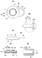
図2は、図1のコルゲート管継手の規制リングを示す図である。(A)は上側から見た平面図であり、(B)は(A)のA部拡大図であり、(C)は正面図であり、(D)は(C)のB−B線断面図であり、(E)は(D)のC部拡大断面図である。
規制リング90は、図1に示すように、リテーナ押え50の内周面入口56に配置されている。この規制リング90は、図2に示すように、円環状のキャップ91とU字状の取っ手93を備えている。
Next, the restriction ring 90 will be described with reference to FIGS. 1 and 2.
FIG. 2 is a view showing a regulating ring of the corrugated pipe joint of FIG. (A) is the top view seen from the upper side, (B) is the A section enlarged view of (A), (C) is a front view, (D) is the BB sectional view of (C). It is a figure and (E) is the C section expanded sectional view of (D).
As shown in FIG. 1, the restriction ring 90 is disposed at the inner peripheral surface inlet 56 of the retainer presser 50. As shown in FIG. 2, the regulation ring 90 includes an annular cap 91 and a U-shaped handle 93.

キャップ91には、内周側にコルゲート管の挿通を規制する筒状規制部95が突設され、外周側にリテーナ押え50の張出部51の上部外周面51a(図1(B)参照)に被さる筒状被覆部97が突設されている。さらに、キャップ91には、用済みとなった規制リング90を径方向に割ってリテーナ押え50から離脱させるために、該割り箇所99となる切欠き部99aと破断部99bが外周側と内周側にそれぞれ形成されている。   The cap 91 is provided with a cylindrical restricting portion 95 for restricting the insertion of the corrugated tube on the inner peripheral side, and an upper outer peripheral surface 51a of the protruding portion 51 of the retainer presser 50 on the outer peripheral side (see FIG. 1B). A cylindrical covering portion 97 is provided so as to cover the surface. Further, the cap 91 has a cut-out portion 99a and a fracture portion 99b which become the split portions 99 in order to split the used regulating ring 90 in the radial direction and disengage it from the retainer presser 50. Each is formed on the side.

筒状規制部95の内周部95aの内径は、コルゲート管の外径よりもやや大きくなるように形成されている。例えば、呼び径8A、15A、25Aのコルゲート管の外径は、11.5mm、18.4mm、30.8mmであるが、それらに対応する筒状規制部95の内周部95aの内径は、11.8mm〜12.2mm、18.7mm〜19.1mm、31.1mm〜31.5mmとなっている。この内周部95aはリテーナ押え50の内周面入口56と同心となるように配置されている。このため、コルゲート管が限度以上に扁平に変形しているときは、該内周部95aで挿通が妨げられて継手本体10の内孔11内に挿入できないようになっている。そして、形状良好なコルゲート管のみが該内周部95aを挿通して継手本体10の内孔11内に挿入できるようになっている。   The inner diameter of the inner peripheral portion 95a of the cylindrical restriction portion 95 is formed to be slightly larger than the outer diameter of the corrugated tube. For example, the outer diameters of the corrugated pipes having nominal diameters 8A, 15A, and 25A are 11.5 mm, 18.4 mm, and 30.8 mm, but the inner diameter of the inner peripheral part 95a of the cylindrical restricting part 95 corresponding to them is They are 11.8 mm to 12.2 mm, 18.7 mm to 19.1 mm, and 31.1 mm to 31.5 mm. The inner peripheral portion 95 a is disposed so as to be concentric with the inner peripheral surface inlet 56 of the retainer presser 50. For this reason, when the corrugated tube is deformed to be flatter than the limit, insertion is prevented by the inner peripheral portion 95a so that the corrugated tube cannot be inserted into the inner hole 11 of the joint body 10. Only a corrugated pipe having a good shape can be inserted into the inner hole 11 of the joint body 10 through the inner peripheral portion 95a.

筒状被覆部97の内周部97aは、リテーナ押え50の張出部51の上部外周面51a(図1(B)参照)に嵌め込み可能なように形成されている。そして、該内周部97aには、抜け止め用の円環状の凸部97cが形成され、該上部外周面51aには、上記凸部97cと噛み合う抜け止め用の円環状の凹部51c(図1(B)参照)が形成されている。以上により、該上部外周面51aを基準として規制リング90が位置決めされるので、リテーナ押え50の内周面入口56と該内周部97aとを高精度に芯出しして形状良好なコルゲート管をスムーズに挿通させることができる。また、規制リング90がリテーナ押え50から抜け難い構造となるため、規制リング90が不意に脱落するようなことはなく、規制リング90を予め備えたコルゲート管継手1として施工の工数を低減させることができる。   The inner peripheral portion 97a of the cylindrical covering portion 97 is formed so as to be fitted into the upper outer peripheral surface 51a (see FIG. 1B) of the overhang portion 51 of the retainer retainer 50. An annular convex portion 97c for retaining is formed on the inner peripheral portion 97a, and an annular concave portion 51c (FIG. 1) for retaining the mesh with the convex portion 97c is formed on the upper outer peripheral surface 51a. (B) is formed. As described above, since the regulating ring 90 is positioned with reference to the upper outer peripheral surface 51a, the inner peripheral surface inlet 56 of the retainer presser 50 and the inner peripheral portion 97a are centered with high accuracy to form a corrugated tube having a good shape. It can be inserted smoothly. In addition, since the restriction ring 90 has a structure that is difficult to be removed from the retainer presser 50, the restriction ring 90 is not accidentally dropped off, and the number of construction work can be reduced as the corrugated pipe joint 1 provided with the restriction ring 90 in advance. Can do.

切欠き部99aは、筒状被覆部97の外周面から径方向内側に延びる帯状に切り欠かれている。破断部99bは、筒状規制部95の内周部95aにおいて円弧状に形成されている。この破断部99bは、キャップ91が切欠き部99aにて拡開しないように切欠き部99aの端面を繋ぐように形成されている。図2(B)に示すように、破断部99bの幅aは、切欠き部99aの幅bよりも大きくなるように形成されている。これにより、詳細は後述するが、不要になった規制リング90を割り箇所99で割ってリテーナ押え50から離脱させる際に、破断部99bとコルゲート管との接触を防止することができる。なお、破断部99bの中央には、破断を容易にするための切れ込み99dが入れられている。   The notch 99 a is notched in a band shape extending radially inward from the outer peripheral surface of the cylindrical covering portion 97. The breaking portion 99b is formed in an arc shape in the inner peripheral portion 95a of the cylindrical regulating portion 95. The broken portion 99b is formed so as to connect the end surfaces of the notch 99a so that the cap 91 does not expand at the notch 99a. As shown in FIG. 2B, the width a of the fracture portion 99b is formed to be larger than the width b of the notch 99a. Thereby, although the details will be described later, when the regulating ring 90 that is no longer needed is divided by the split portion 99 to be detached from the retainer presser 50, contact between the fracture portion 99b and the corrugated pipe can be prevented. In addition, a cut 99d for facilitating breakage is provided in the center of the breakage portion 99b.

取っ手93は、割り箇所99と180°対向したキャップ91の外周に径方向外側に突き出るように一体的に形成されている。形状良好なコルゲート管をリテーナ押え50の内周面入口56から継手本体10の内孔11内に一旦挿入した後は、この取っ手93に指を掛けて径方向外側に引っ張ることにより、用済みとなった規制リング90を割り箇所99で割ってリテーナ押え50から離脱させることができる。   The handle 93 is integrally formed so as to protrude radially outward on the outer periphery of the cap 91 facing the split portion 99 by 180 °. Once the corrugated pipe having a good shape is inserted into the inner hole 11 of the joint body 10 from the inner peripheral surface inlet 56 of the retainer retainer 50, the handle 93 is hooked with a finger and pulled outward in the radial direction. The resulting restriction ring 90 can be divided by the split portion 99 and detached from the retainer presser 50.

以上のような構成の規制リング90を備えたコルゲート管継手1によれば、コルゲート管が限度以上に扁平に変形していたときは、該コルゲート管をリテーナ押え50の内周面入口56から継手本体10の内孔内11に挿入しようとしても、該入口56に配置されている規制リング90を挿通させることができない。したがって、コルゲート管の配管接続の施工において、形状良好なコルゲート管のみを挿通させて当該外面で気密シールすることにより気密性を十分に確保できる。   According to the corrugated pipe joint 1 provided with the regulating ring 90 having the above-described configuration, when the corrugated pipe is deformed to be flatter than the limit, the corrugated pipe is joined from the inner peripheral surface inlet 56 of the retainer presser 50. Even when trying to insert into the inner hole 11 of the main body 10, the regulating ring 90 disposed at the inlet 56 cannot be inserted. Therefore, in the construction of corrugated pipe connection, it is possible to sufficiently secure the airtightness by inserting only the corrugated pipe having a good shape and hermetically sealing the outer surface.

次に、前述の構成を有するコルゲート管継手1の作用及び使用方法を、主に図3〜図7に基づき説明する。
図3(A)は本コルゲート管継手のコルゲート管挿入途中の状態(規制リング通過状態)を示す断面図であり、図3(B)は図3(A)のA部拡大断面図である。
図4(A)、(B)、(C)、(D)は、図2の規制リングの離脱状態を順に示す図である。
図5(A)は本コルゲート管継手のコルゲート管挿入途中の状態(規制リングを外しストッパーの手前まで挿入状態)を示す断面図であり、図5(B)は図5(A)のA部拡大断面図である。
図6(A)は本コルゲート管継手のコルゲート管挿入完了状態(ストッパー通過状態)を示す断面図であり、図6(B)は図6(A)のA部拡大断面図である。
図7(A)は本コルゲート管継手のコルゲート管施工完了状態(位置決めカラーを外しリテーナ押えを押し込んだ状態)を示す断面図であり、図7(B)は図7(A)のA部拡大断面図である。
Next, the operation and method of use of the corrugated pipe joint 1 having the above-described configuration will be described mainly based on FIGS.
FIG. 3A is a cross-sectional view showing a state in which the corrugated pipe is inserted into the corrugated pipe joint (a state in which the regulating ring is passed), and FIG. 3B is an enlarged cross-sectional view of a portion A in FIG.
FIGS. 4A, 4B, 4C, and 4D are diagrams sequentially illustrating the disengagement state of the regulating ring in FIG.
FIG. 5A is a cross-sectional view showing a state in which the corrugated pipe is being inserted into the corrugated pipe joint (a state in which the regulating ring is removed and inserted to the front of the stopper), and FIG. 5B is a part A of FIG. It is an expanded sectional view.
FIG. 6A is a cross-sectional view showing a corrugated pipe insertion completion state (stopper passing state) of the corrugated pipe joint, and FIG. 6B is an enlarged cross-sectional view of a portion A in FIG.
FIG. 7 (A) is a cross-sectional view showing the corrugated pipe construction completion state of the corrugated pipe joint (state where the positioning collar is removed and the retainer presser is pushed in), and FIG. 7 (B) is an enlarged view of portion A of FIG. 7 (A). It is sectional drawing.

図3(A)に示すように、コルゲート管Tを規制リング90の内周部95aに挿通してリテーナ押え50の内周面入口56から継手本体10の内孔11内に挿入する。このとき、コルゲート管Tが限度以上に扁平に変形していると該内周部95aを挿通することができないが、形状良好であれば図3(B)に示すように、該内周部95aと接触すること無くスムーズに挿通できる。   As shown in FIG. 3A, the corrugated tube T is inserted into the inner peripheral portion 95 a of the regulating ring 90 and inserted into the inner hole 11 of the joint body 10 from the inner peripheral surface inlet 56 of the retainer retainer 50. At this time, if the corrugated tube T is deformed so as to be flatter than the limit, the inner peripheral portion 95a cannot be inserted. However, if the shape is good, the inner peripheral portion 95a is shown in FIG. Can be inserted smoothly without touching.

次に、用済みとなった規制リング90をリテーナ押え50から離脱させる。図4(A)の状態の規制リング90の取っ手93に指を掛けて径方向外側(図示矢印a方向)に引っ張る。すると、図3(B)に示すように、規制リング90の筒状被覆部97は張出部51の上部外周面51aに被さっているため、図4(B)に示すように、破断部99bが切断し、切欠き部99aが上部外周面51aに接触しながら周方向(図示矢印b方向)に移動し、割り箇所99が拡開していく。さらに取っ手93を径方向外側に引っ張ると、図4(C)、(D)に示すように、割り箇所99がさらに拡開する。   Next, the used regulation ring 90 is detached from the retainer presser 50. A finger is put on the handle 93 of the regulating ring 90 in the state of FIG. 4A and pulled outward in the radial direction (in the direction of arrow a in the figure). Then, as shown in FIG. 3B, since the cylindrical covering portion 97 of the regulating ring 90 covers the upper outer peripheral surface 51a of the overhanging portion 51, as shown in FIG. 4B, the fracture portion 99b. The cut portion 99a moves in the circumferential direction (in the direction of the arrow b in the figure) while contacting the upper outer peripheral surface 51a, and the split portion 99 is expanded. When the handle 93 is further pulled outward in the radial direction, the split portion 99 is further expanded as shown in FIGS.

図4(B)から(D)に至る間、破断部99bはコルゲート管Tの外周面から所定間隔を保って移動する。これは、図2(B)で説明したように、破断部99bの幅aが、切欠き部99aの幅bよりも大きくなるように形成されているためである。したがって、破断部99bはコルゲート管Tに直接接触することは無く、コルゲート管Tの傷付け等を防止できる。そして、最終的には図4(D)に示すように、破断部99bの間隔はコルゲート管Tの直径よりも大きく開かれるので、用済みとなった規制リング90をリテーナ押え50から離脱させることができる。   4B to 4D, the fracture portion 99b moves from the outer peripheral surface of the corrugated tube T at a predetermined interval. This is because, as described with reference to FIG. 2B, the width a of the fracture portion 99b is formed to be larger than the width b of the notch 99a. Therefore, the broken portion 99b does not directly contact the corrugated tube T, and the corrugated tube T can be prevented from being damaged. Finally, as shown in FIG. 4 (D), since the gap between the fracture portions 99b is opened larger than the diameter of the corrugated tube T, the used regulation ring 90 is detached from the retainer presser 50. Can do.

図5(A)に示すように、コルゲート管Tを継手本体10の内孔11内にさらに挿入すると、図5(B)に示すように、コルゲート管Tの先端が、リテーナ40内からパッキン30内を順に通って、ストッパー70へと至ってコルゲート管T先端の環状凸部tがストッパー70の各係合片部73に当たる。   When the corrugated tube T is further inserted into the inner hole 11 of the joint body 10 as shown in FIG. 5A, the tip of the corrugated tube T is inserted into the packing 30 from the retainer 40 as shown in FIG. Through the inside, it reaches the stopper 70, and the annular convex part t at the tip of the corrugated tube T hits each engagement piece 73 of the stopper 70.

ストッパー70の係合片部73の先端部内径は、コルゲート管Tの環状凸部tの外径よりも小さい。そのため、図6(A)に示すように、コルゲート管Tをさらに押し込むと、図6(B)に示すように、コルゲート管T先端の環状凸部tは各係合片部73を押し広げつつ押し込められる。   The inner diameter of the distal end portion of the engagement piece 73 of the stopper 70 is smaller than the outer diameter of the annular convex portion t of the corrugated tube T. Therefore, as shown in FIG. 6 (A), when the corrugated tube T is further pushed in, as shown in FIG. 6 (B), the annular convex portion t at the tip of the corrugated tube T pushes the engaging piece portions 73 apart. Can be pushed in.

コルゲート管T先端の環状凸部tが各係合片部73を乗り越えると、図3に示すように、各係合片部73が元の状態に弾性復帰し、コルゲート管T先端の環状凹部ttに係合される。この時点で、作業者がコルゲート管Tを引き抜こうとしても、コルゲート管T先端の環状凹部ttにストッパー70の係合片部73先端が当たるので、この感触を作業者が手で体感できる。すなわち、ストッパー70は、コルゲート管Tが押し込みエンドであることを作業者に体感させて、接続時の操作ミスを防止する役割を果たす。   When the annular convex portion t at the tip of the corrugated tube T gets over each engaging piece portion 73, as shown in FIG. 3, each engaging piece portion 73 is elastically restored to its original state, and the annular concave portion tt at the tip of the corrugated tube T is obtained. Is engaged. At this time, even if the operator tries to pull out the corrugated tube T, the tip of the engaging piece 73 of the stopper 70 hits the annular recess tt at the tip of the corrugated tube T, so that the operator can feel this feeling by hand. That is, the stopper 70 plays a role of preventing an operator from making an operation mistake at the time of connection by letting the operator feel that the corrugated tube T is the push-in end.

次いで、図7(A)に示すように、位置決めカラー60を外し、リテーナ押え50を継手本体10の奥側に向けてスライドさせつつ押し込む。すると、リテーナ押え50に外嵌しているストップリング67が、継手本体10の上内孔部21内の上リング溝22において、角溝22aからテーパ溝22bへと滑りつつ押し縮められ、リテーナ押え50と継手本体10との連結状態が一旦解除される。   Next, as shown in FIG. 7A, the positioning collar 60 is removed, and the retainer presser 50 is pushed in while sliding toward the back side of the joint body 10. Then, the stop ring 67 externally fitted to the retainer presser 50 is compressed in the upper ring groove 22 in the upper inner hole portion 21 of the joint body 10 while sliding from the square groove 22a to the tapered groove 22b. The connection state between the joint body 50 and the joint body 10 is once released.

そして、図7(B)に示すように、ストップリング67が継手本体10の上内孔部21内の下リング溝23にまで至ると、ストップリング67自身が弾性で拡径して下リング溝23の上角溝23aに入り込み、リテーナ押え50と継手本体10とが再び連結される。この際、リテーナ押え50のスライドスリーブ部53下端内周縁の内周テーパ面57が、リテーナ40の各分割片43の外周テーパ面47に接触する。すると、リテーナ40の各分割片43が内径方向に縮まって、各爪45の先が徐々にすぼまっていく。   As shown in FIG. 7B, when the stop ring 67 reaches the lower ring groove 23 in the upper inner hole portion 21 of the joint body 10, the stop ring 67 itself elastically expands in diameter, and the lower ring groove. 23, the retainer presser 50 and the joint body 10 are connected again. At this time, the inner peripheral tapered surface 57 at the inner peripheral edge of the lower end of the slide sleeve portion 53 of the retainer presser 50 contacts the outer peripheral tapered surface 47 of each divided piece 43 of the retainer 40. Then, each divided piece 43 of the retainer 40 is contracted in the inner diameter direction, and the tip of each claw 45 gradually narrows.

そして、最終的には、スライドスリーブ部53の内周テーパ面57と各分割片43の外周テーパ面47とが面接触した状態で、各爪45がコルゲート管Tの環状凹部に係合する。この時点で、リテーナ40は、リテーナ押え50とパッキン30との間で固定された状態となり、このリテーナ40、リテーナ押え50及びストップリング67によって、継手本体10からコルゲート管Tが抜き出し不能に固定される。   Finally, each claw 45 engages with the annular recess of the corrugated tube T in a state where the inner peripheral tapered surface 57 of the slide sleeve portion 53 and the outer peripheral tapered surface 47 of each divided piece 43 are in surface contact. At this time, the retainer 40 is fixed between the retainer retainer 50 and the packing 30, and the corrugated tube T is fixed so as not to be extracted from the joint body 10 by the retainer 40, the retainer retainer 50 and the stop ring 67. The

なお、コルゲート管Tを継手1に接続した後で、同コルゲート管Tを抜き取らなければならないような場合には、図7において分解用リング61を切断して取り外し、リテーナ押え50を継手本体10の奥側に向けてさらに押し込む。すると、ストップリング67が継手本体10の上内孔部21内の下リング溝23において、上角溝23aから下角溝23bに入り込み、ストップリング67がリテーナ押え50のストップリング溝65内から外れる。これで、継手本体10とリテーナ押え50との連結が解除され、コルゲート管Tを上側から抜き取ることができる。   If the corrugated pipe T must be removed after the corrugated pipe T is connected to the joint 1, the disassembly ring 61 is cut and removed in FIG. 7, and the retainer presser 50 is attached to the joint body 10. Push further toward the back. Then, the stop ring 67 enters the lower corner groove 23 b from the upper corner groove 23 a in the lower ring groove 23 in the upper inner hole portion 21 of the joint body 10, and the stop ring 67 is detached from the stop ring groove 65 of the retainer presser 50. Thus, the connection between the joint body 10 and the retainer presser 50 is released, and the corrugated pipe T can be extracted from the upper side.

図8は本発明の第2の形態に係るコルゲート管継手の全体構成(コルゲート管挿入途中状態)を示す断面図である。
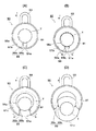
図9は、図8のコルゲート管継手の規制リングを示す図である。(A)は上側から見た平面図であり、(B)は正面図であり、(C)は(A)のA−A線断面図である。
図10は、図9の規制リングを示す斜視図である。(A)は自由状態を示す図であり、(B)は縮径状態を示す図である。
なお、このコルゲート管継手2は、図1に示すコルゲート管継手1の規制リング90が規制リング80に変更になった点以外は該継手1と同一構成であるため、同一部は同一番号を付して示して詳細な説明は省略する。
FIG. 8 is a cross-sectional view showing the overall configuration of the corrugated pipe joint according to the second embodiment of the present invention (in the middle of corrugated pipe insertion).
FIG. 9 is a view showing a regulating ring of the corrugated pipe joint of FIG. (A) is the top view seen from the upper side, (B) is a front view, (C) is the sectional view on the AA line of (A).
FIG. 10 is a perspective view showing the regulating ring of FIG. (A) is a figure which shows a free state, (B) is a figure which shows a diameter-reduced state.
The corrugated pipe joint 2 has the same configuration as the joint 1 except that the restriction ring 90 of the corrugated pipe joint 1 shown in FIG. Therefore, detailed description will be omitted.

規制リング80は、図8に示すように、リテーナ押え50の内周面入口56に配置されている。この規制リング80は、図9に示すように、円弧状の割れ目89を有する円環状のキャップ81と径方向両外側に突き出る2つの取っ手83を備えている。規制リング80は、自由状態で拡開状態(図10(A)の状態)にある該割れ目89を縮閉状態(図10(B)の状態)にして該内周面入口56に嵌め込み、もしくは該内周面入口56から離脱するようになっている。割れ目89が縮閉状態にあるキャップ81には、内周側にコルゲート管の挿通を規制する筒状規制部85が形成され、下端側にリテーナ押え50の内周面入口56に係合する内つば部87が突設されている。   As shown in FIG. 8, the restriction ring 80 is disposed at the inner peripheral surface inlet 56 of the retainer presser 50. As shown in FIG. 9, the restriction ring 80 includes an annular cap 81 having an arcuate crack 89 and two handles 83 protruding outward in the radial direction. The restriction ring 80 is fitted into the inner peripheral surface inlet 56 with the crack 89 in a free state in an expanded state (the state shown in FIG. 10A) in a contracted state (the state shown in FIG. 10B), or The inner surface 56 is separated from the inlet 56. The cap 81 in which the crack 89 is in a closed state is formed with a cylindrical restricting portion 85 for restricting the insertion of the corrugated pipe on the inner peripheral side, and is engaged with the inner peripheral surface inlet 56 of the retainer presser 50 on the lower end side. A collar portion 87 is projected.

縮閉状態のときの筒状規制部85の内周部85aの内径は、コルゲート管の外径よりもやや大きくなるように形成されている。例えば、呼び径8A、15A、25Aのコルゲート管の外径は、11.5mm、18.4mm、30.8mmであるが、それらに対応する筒状規制部85の内周部85aの内径は、11.8mm〜12.2mm、18.7mm〜19.1mm、31.1mm〜31.5mmとなっている。この内周部85aはリテーナ押え50の内周面入口56と同心となるように形成されている。このため、コルゲート管が限度以上に扁平に変形しているときは、該内周部85aで挿通が妨げられて継手本体10の内孔11内に挿入できないようになっている。そして、形状良好なコルゲート管のみが該内周部85aを挿通して継手本体10の内孔11内に挿入できるようになっている。   An inner diameter of the inner peripheral portion 85a of the cylindrical restriction portion 85 in the contracted state is formed to be slightly larger than the outer diameter of the corrugated tube. For example, the outer diameters of the corrugated pipes having nominal diameters 8A, 15A, and 25A are 11.5 mm, 18.4 mm, and 30.8 mm, but the inner diameter of the inner peripheral part 85a of the cylindrical restricting part 85 corresponding to them is They are 11.8 mm to 12.2 mm, 18.7 mm to 19.1 mm, and 31.1 mm to 31.5 mm. The inner peripheral portion 85 a is formed so as to be concentric with the inner peripheral surface inlet 56 of the retainer presser 50. For this reason, when the corrugated pipe is deformed to be flatter than the limit, the insertion is prevented by the inner peripheral portion 85a so that the corrugated pipe cannot be inserted into the inner hole 11 of the joint body 10. Only a corrugated pipe having a good shape can be inserted into the inner hole 11 of the joint body 10 through the inner peripheral portion 85a.

縮閉状態のときの内つば部87の外周部87aは、リテーナ押え50の内周面入口56に係合可能なように形成されている。規制リング80は拡開方向に復元力が働いているので、該内つば部87は該内周面入口56から容易に抜けないようになっている。以上により、該内周面入口56を基準として規制リング80が位置決めされるので、該内周面入口56と該内周部85aとを高精度に芯出しして形状良好なコルゲート管をスムーズに挿通させることができる。また、規制リング80がリテーナ押え50から抜け難い構造であるため、規制リング80が不意に脱落するようなことはなく、規制リング80を予め備えたコルゲート管継手1として施工の工数を低減させることができる。   The outer peripheral portion 87 a of the inner collar portion 87 in the contracted state is formed so as to be engageable with the inner peripheral surface inlet 56 of the retainer presser 50. Since the restricting ring 80 has a restoring force in the expanding direction, the inner collar portion 87 is not easily removed from the inner peripheral surface inlet 56. As described above, since the regulating ring 80 is positioned with reference to the inner peripheral surface inlet 56, the inner peripheral surface inlet 56 and the inner peripheral portion 85a are centered with high accuracy to smoothly form a corrugated pipe having a good shape. It can be inserted. In addition, since the restriction ring 80 has a structure that is difficult to be removed from the retainer presser 50, the restriction ring 80 is not unexpectedly dropped, and the corrugated pipe joint 1 provided with the restriction ring 80 in advance reduces the number of work steps. Can do.

取っ手83は、キャップ81外周における割れ目89の両側において径方向外側に突き出るように一体的に形成されている。形状良好なコルゲート管をリテーナ押え50の内周面入口56から継手本体10の内孔11内に一旦挿入した後は、この取っ手83に指を掛けて径方向内側に圧縮することにより、不要になった規制リング80をリテーナ押え50から離脱させることができる。   The handle 83 is integrally formed so as to protrude radially outward on both sides of the crack 89 on the outer periphery of the cap 81. Once the corrugated pipe having a good shape is inserted into the inner hole 11 of the joint body 10 from the inner peripheral surface inlet 56 of the retainer retainer 50, it is unnecessary by placing the finger on the handle 83 and compressing it radially inward. The restricted regulating ring 80 can be detached from the retainer presser 50.

以上のような構成の規制リング80を備えたコルゲート管継手2によれば、コルゲート管が限度以上に扁平に変形していたときは、該コルゲート管をリテーナ押え50の内周面入口56から継手本体10の内孔内11に挿入しようとしても、該入口56に配置されている規制リング80を挿通させることができない。したがって、コルゲート管の配管接続の施工において、形状良好なコルゲート管のみを挿通させて当該外面で気密シールすることにより気密性を十分に確保できる。   According to the corrugated pipe joint 2 provided with the regulating ring 80 having the above-described configuration, when the corrugated pipe is deformed to be flatter than the limit, the corrugated pipe is joined from the inner peripheral surface inlet 56 of the retainer presser 50. Even when trying to insert into the inner hole 11 of the main body 10, the regulating ring 80 disposed at the inlet 56 cannot be inserted. Therefore, in the construction of corrugated pipe connection, it is possible to sufficiently secure the airtightness by inserting only the corrugated pipe having a good shape and hermetically sealing the outer surface.

図1(A)は本発明の第1の形態に係るコルゲート管継手の全体構成(施工前状態)を示す断面図であり、図1(B)は図1(A)のA部拡大断面図である。FIG. 1 (A) is a cross-sectional view showing the overall configuration (pre-construction state) of the corrugated pipe joint according to the first embodiment of the present invention, and FIG. 1 (B) is an enlarged cross-sectional view of a portion A in FIG. 1 (A). It is. 図1のコルゲート管継手の規制リングを示す図である。(A)は上側から見た平面図であり、(B)は(A)のA部拡大図であり、(C)は正面図であり、(D)は(C)のB−B線断面図であり、(E)は(D)のC部拡大断面図である。It is a figure which shows the control ring of the corrugated pipe joint of FIG. (A) is the top view seen from the upper side, (B) is the A section enlarged view of (A), (C) is a front view, (D) is the BB sectional view of (C). It is a figure and (E) is the C section expanded sectional view of (D). 図3(A)は本コルゲート管継手のコルゲート管挿入途中の状態(キャップ通過状態)を示す断面図であり、図3(B)は図3(A)のA部拡大断面図である。3A is a cross-sectional view showing a state in which the corrugated pipe is being inserted into the corrugated pipe joint (cap passing state), and FIG. 3B is an enlarged cross-sectional view of a portion A in FIG. 図4(A)、(B)、(C)、(D)は、図2の規制リングの離脱状態を順に示す図である。FIGS. 4A, 4B, 4C, and 4D are diagrams sequentially illustrating the disengagement state of the regulating ring in FIG. 図5(A)は本コルゲート管継手のコルゲート管挿入途中の状態(キャップを外しストッパーの手前まで挿入状態)を示す断面図であり、図5(B)は図5(A)のA部拡大断面図である。FIG. 5 (A) is a cross-sectional view showing a state in which the corrugated pipe is being inserted into the corrugated pipe joint (when the cap is removed and inserted to the front of the stopper), and FIG. It is sectional drawing. 図6(A)は本コルゲート管継手のコルゲート管挿入完了状態(ストッパー通過状態)を示す断面図であり、図6(B)は図6(A)のA部拡大断面図である。FIG. 6A is a cross-sectional view showing a corrugated pipe insertion completion state (stopper passing state) of the corrugated pipe joint, and FIG. 6B is an enlarged cross-sectional view of a portion A in FIG. 図7(A)は本コルゲート管継手のコルゲート管施工完了状態(位置決めカラーを外しリテーナ押えを押し込んだ状態)を示す断面図であり、図7(B)は図7(A)のA部拡大断面図である。FIG. 7 (A) is a cross-sectional view showing the corrugated pipe construction completion state of the corrugated pipe joint (state where the positioning collar is removed and the retainer presser is pushed in), and FIG. 7 (B) is an enlarged view of portion A of FIG. 7 (A). It is sectional drawing. 本発明の第2の形態に係るコルゲート管継手の全体構成(コルゲート管挿入途中状態)を示す断面図である。It is sectional drawing which shows the whole structure (corrugated pipe insertion middle state) of the corrugated pipe joint which concerns on the 2nd form of this invention. 図8のコルゲート管継手の規制リングを示す図である。(A)は上側から見た平面図であり、(B)は正面図であり、(C)は(A)のA−A線断面図である。It is a figure which shows the control ring of the corrugated pipe coupling of FIG. (A) is the top view seen from the upper side, (B) is a front view, (C) is the sectional view on the AA line of (A). 図9の規制リングを示す斜視図である。(A)は自由状態を示す図であり、(B)は縮径状態を示す図である。FIG. 10 is a perspective view showing the restriction ring of FIG. 9. (A) is a figure which shows a free state, (B) is a figure which shows a diameter-reduced state. 建物のガス配管の例を模式的に示す図である。It is a figure which shows the example of the gas piping of a building typically.

符号の説明Explanation of symbols

1、2・・・コルゲート管継手、10・・・継手本体、11・・・内孔、30・・・パッキン、40・・・リテーナ、50・・・リテーナ押え、51c・・・凹部、56・・・内周面入口、70・・・ストッパー、80、90・・・規制リング、81、91・・・キャップ、83、93・・・取っ手、85、95・・・筒状規制部、85a、95a、97a・・・内周部、87・・・内つば部、87a・・・外周部、89・・・割れ目、97・・・筒状被覆部、97c・・・凸部、99・・・割り箇所、99a・・・切欠き部、99b・・・破断部、T・・・コルゲート管 DESCRIPTION OF SYMBOLS 1, 2 ... Corrugated pipe joint, 10 ... Joint main body, 11 ... Inner hole, 30 ... Packing, 40 ... Retainer, 50 ... Retainer presser, 51c ... Recessed part, 56 ... Inner peripheral surface inlet, 70 ... Stopper, 80, 90 ... Regulator ring, 81, 91 ... Cap, 83, 93 ... Handle, 85, 95 ... Cylinder regulator, 85a, 95a, 97a ... inner peripheral part, 87 ... inner collar part, 87a ... outer peripheral part, 89 ... crack, 97 ... cylindrical covering part, 97c ... convex part, 99 ... Split part, 99a ... Notch, 99b ... Broken part, T ... Corrugated tube

Claims (4)

外周に環状の凹凸が形成されたコルゲート管が挿入される内孔を有する筒状の継手本体と、
前記内孔内に配置された、前記コルゲート管の外面に当接するパッキンと、
前記内孔内に配置された、前記コルゲート管の環状凹部に係合する爪を有するリテーナと、
内周面に前記コルゲート管が挿通され、前記リテーナを押さえる筒状のリテーナ押えと、を備え、
さらに、前記リテーナ押えの内周面入口に配置された、扁平に変形した前記コルゲート管が挿通不能な内周部を有する規制リングを備えることを特徴とするコルゲート管継手。
A cylindrical joint body having an inner hole into which a corrugated pipe having an annular unevenness formed on the outer periphery is inserted;
A packing disposed in the inner hole and in contact with the outer surface of the corrugated pipe;
A retainer having a claw disposed in the inner hole and engaged with an annular recess of the corrugated tube;
The corrugated tube is inserted through an inner peripheral surface, and a cylindrical retainer presser that holds the retainer is provided.
Furthermore, the corrugated pipe joint is provided with a regulating ring having an inner peripheral portion which is disposed at the inner peripheral surface entrance of the retainer presser and into which the corrugated pipe deformed into a flat shape cannot be inserted.
前記規制リングに割れ目が形成されていて、前記リテーナ押えの内周面入口から離脱容易となっており、
ここで、前記規制リングが前記リテーナ押えの入口に被さる中空のキャップ状の部材であって、その内周側には、前記コルゲート管の挿通を規制する筒状規制部が設けられているとともに、その外周側には前記リテーナ押えに被さる筒状被覆部が設けられており、
前記割れ目として、前記筒状規制部の内周部において円弧状に形成されている破断部、及び、前記筒状被覆部の外周面から径方向内側に延びる帯状に切り欠かれた切欠き部、が設けられており、
該破断部は、前記規制リングが前記切欠き部の端面を繋ぐように形成されていることを特徴とする、請求項1記載のコルゲート管継手。
A crack is formed in the restriction ring, and it is easy to remove from the inner peripheral surface entrance of the retainer presser ,
Here, the restricting ring is a hollow cap-shaped member that covers the inlet of the retainer presser, and on the inner peripheral side thereof, a tubular restricting portion that restricts the insertion of the corrugated pipe is provided, A cylindrical covering portion covering the retainer presser is provided on the outer peripheral side,
As the fissure, a rupture portion formed in an arc shape in an inner peripheral portion of the cylindrical regulating portion, and a notch portion cut out in a strip shape extending radially inward from the outer peripheral surface of the cylindrical covering portion, Is provided,
The corrugated pipe joint according to claim 1 , wherein the fracture portion is formed so that the restriction ring connects end faces of the notches .
前記規制リングが、前記リテーナ押え外周面に被っており、該リング割り時に該外周面に沿って拡開することを特徴とする、請求項2記載のコルゲート管継手。   The corrugated pipe joint according to claim 2, wherein the restricting ring covers the outer circumferential surface of the retainer presser and expands along the outer circumferential surface when the ring is split. 前記規制リングが、割り箇所となる切欠き部及び破断部を外周側及び内周側にそれぞれ形成されており、該破断部の幅が該切欠き部の幅よりも大きいことを特徴とする、請求項3記載のコルゲート管継手。   The regulating ring is formed with a notch portion and a rupture portion which are split portions on the outer peripheral side and the inner peripheral side, respectively, and the width of the rupture portion is larger than the width of the notch portion, The corrugated pipe joint according to claim 3.
JP2007172854A 2007-06-29 2007-06-29 Corrugated fitting Active JP5064907B2 (en)

Priority Applications (1)

Application Number Priority Date Filing Date Title
JP2007172854A JP5064907B2 (en) 2007-06-29 2007-06-29 Corrugated fitting

Applications Claiming Priority (1)

Application Number Priority Date Filing Date Title
JP2007172854A JP5064907B2 (en) 2007-06-29 2007-06-29 Corrugated fitting

Publications (3)

Publication Number Publication Date
JP2009014005A JP2009014005A (en) 2009-01-22
JP2009014005A5 JP2009014005A5 (en) 2010-06-24
JP5064907B2 true JP5064907B2 (en) 2012-10-31

Family

ID=40355160

Family Applications (1)

Application Number Title Priority Date Filing Date
JP2007172854A Active JP5064907B2 (en) 2007-06-29 2007-06-29 Corrugated fitting

Country Status (1)

Country Link
JP (1) JP5064907B2 (en)

Families Citing this family (1)

* Cited by examiner, † Cited by third party
Publication number Priority date Publication date Assignee Title
US20100254758A1 (en) * 2009-04-06 2010-10-07 International Business Machines Corporation Apparatus and method for forming a mechanical, fluid-tight connection

Family Cites Families (8)

* Cited by examiner, † Cited by third party
Publication number Priority date Publication date Assignee Title
JPS5969617U (en) * 1982-10-29 1984-05-11 未来工業株式会社 Connection device for corrugated conduit
JPS59148860U (en) * 1983-03-25 1984-10-04 富士通株式会社 Cover locking device
JPS59173418U (en) * 1983-05-04 1984-11-20 未来工業株式会社 Conduit coupling device
JPS6192113A (en) * 1984-10-11 1986-05-10 未来工業株式会社 Waterproof joint structure of corrugated conduit tube made of synthetic resin used for underground wiring
JPH0211679Y2 (en) * 1985-08-13 1990-03-27
JPH03129410U (en) * 1990-04-11 1991-12-26
JP4236330B2 (en) * 1999-04-16 2009-03-11 新和産業株式会社 Fitting for flexible tube
JP4409199B2 (en) * 2003-04-15 2010-02-03 東京瓦斯株式会社 Corrugated fitting

Also Published As

Publication number Publication date
JP2009014005A (en) 2009-01-22

Similar Documents

Publication Publication Date Title
KR101725169B1 (en) Pipe joint
JP5461116B2 (en) Pipe fitting
JP5297689B2 (en) Corrugated fitting
JP2003176888A (en) Insertion type tube fitting
JP5417589B2 (en) Pipe fitting
JP5064907B2 (en) Corrugated fitting
JP2019120309A (en) Metal tube joint
JP5671112B2 (en) Corrugated pipe insertion fitting
JP4633215B2 (en) Corrugated fitting
JP2003028365A (en) Insert type pipe joint
JP4699286B2 (en) Corrugated pipe insertion joint and stopper
JP5010200B2 (en) Corrugated pipe insertion fitting
JP5033516B2 (en) Corrugated fitting
JP6922342B2 (en) Pipe fitting
JP2008304047A6 (en) Corrugated fitting
JP5028232B2 (en) Fitting for flexible pipe
JP4676860B2 (en) Corrugated pipe insertion joint and stopper
JP6501215B2 (en) Flexible fitting and packing for it
WO2022071504A1 (en) Joint and construction method for flexible tube
JP5207906B2 (en) Fitting for flexible tube
JP2003028363A (en) Insert type pipe joint
JP4523687B2 (en) Corrugated fitting
JP4980778B2 (en) Corrugated pipe insertion fitting
JP5507902B2 (en) Pipe joint mechanism, pipe joint, pipe connection method using pipe joint, pipe connection and separation method using pipe joint, and piping structure
JP2008038925A (en) Insertion joint for corrugated tube

Legal Events

Date Code Title Description
A521 Request for written amendment filed

Free format text: JAPANESE INTERMEDIATE CODE: A523

Effective date: 20100506

A621 Written request for application examination

Free format text: JAPANESE INTERMEDIATE CODE: A621

Effective date: 20100506

A977 Report on retrieval

Free format text: JAPANESE INTERMEDIATE CODE: A971007

Effective date: 20120130

A131 Notification of reasons for refusal

Free format text: JAPANESE INTERMEDIATE CODE: A131

Effective date: 20120316

A521 Request for written amendment filed

Free format text: JAPANESE INTERMEDIATE CODE: A523

Effective date: 20120507

TRDD Decision of grant or rejection written
A01 Written decision to grant a patent or to grant a registration (utility model)

Free format text: JAPANESE INTERMEDIATE CODE: A01

Effective date: 20120807

A01 Written decision to grant a patent or to grant a registration (utility model)

Free format text: JAPANESE INTERMEDIATE CODE: A01

A61 First payment of annual fees (during grant procedure)

Free format text: JAPANESE INTERMEDIATE CODE: A61

Effective date: 20120809

R150 Certificate of patent or registration of utility model

Ref document number: 5064907

Country of ref document: JP

Free format text: JAPANESE INTERMEDIATE CODE: R150

Free format text: JAPANESE INTERMEDIATE CODE: R150

FPAY Renewal fee payment (event date is renewal date of database)

Free format text: PAYMENT UNTIL: 20150817

Year of fee payment: 3

R250 Receipt of annual fees

Free format text: JAPANESE INTERMEDIATE CODE: R250

R250 Receipt of annual fees

Free format text: JAPANESE INTERMEDIATE CODE: R250

R250 Receipt of annual fees

Free format text: JAPANESE INTERMEDIATE CODE: R250

R250 Receipt of annual fees

Free format text: JAPANESE INTERMEDIATE CODE: R250

R250 Receipt of annual fees

Free format text: JAPANESE INTERMEDIATE CODE: R250

R250 Receipt of annual fees

Free format text: JAPANESE INTERMEDIATE CODE: R250

R250 Receipt of annual fees

Free format text: JAPANESE INTERMEDIATE CODE: R250

R250 Receipt of annual fees

Free format text: JAPANESE INTERMEDIATE CODE: R250

R250 Receipt of annual fees

Free format text: JAPANESE INTERMEDIATE CODE: R250