JP5064886B2 - Gear pump - Google Patents
Gear pump Download PDFInfo
- Publication number
- JP5064886B2 JP5064886B2 JP2007133683A JP2007133683A JP5064886B2 JP 5064886 B2 JP5064886 B2 JP 5064886B2 JP 2007133683 A JP2007133683 A JP 2007133683A JP 2007133683 A JP2007133683 A JP 2007133683A JP 5064886 B2 JP5064886 B2 JP 5064886B2
- Authority
- JP
- Japan
- Prior art keywords
- gear
- support shaft
- pump
- driven
- side wall
- Prior art date
- Legal status (The legal status is an assumption and is not a legal conclusion. Google has not performed a legal analysis and makes no representation as to the accuracy of the status listed.)
- Active
Links
Images


Classifications
-
- F—MECHANICAL ENGINEERING; LIGHTING; HEATING; WEAPONS; BLASTING
- F04—POSITIVE - DISPLACEMENT MACHINES FOR LIQUIDS; PUMPS FOR LIQUIDS OR ELASTIC FLUIDS
- F04C—ROTARY-PISTON, OR OSCILLATING-PISTON, POSITIVE-DISPLACEMENT MACHINES FOR LIQUIDS; ROTARY-PISTON, OR OSCILLATING-PISTON, POSITIVE-DISPLACEMENT PUMPS
- F04C2/00—Rotary-piston machines or pumps
- F04C2/08—Rotary-piston machines or pumps of intermeshing-engagement type, i.e. with engagement of co-operating members similar to that of toothed gearing
- F04C2/12—Rotary-piston machines or pumps of intermeshing-engagement type, i.e. with engagement of co-operating members similar to that of toothed gearing of other than internal-axis type
- F04C2/14—Rotary-piston machines or pumps of intermeshing-engagement type, i.e. with engagement of co-operating members similar to that of toothed gearing of other than internal-axis type with toothed rotary pistons
- F04C2/18—Rotary-piston machines or pumps of intermeshing-engagement type, i.e. with engagement of co-operating members similar to that of toothed gearing of other than internal-axis type with toothed rotary pistons with similar tooth forms
-
- F—MECHANICAL ENGINEERING; LIGHTING; HEATING; WEAPONS; BLASTING
- F04—POSITIVE - DISPLACEMENT MACHINES FOR LIQUIDS; PUMPS FOR LIQUIDS OR ELASTIC FLUIDS
- F04C—ROTARY-PISTON, OR OSCILLATING-PISTON, POSITIVE-DISPLACEMENT MACHINES FOR LIQUIDS; ROTARY-PISTON, OR OSCILLATING-PISTON, POSITIVE-DISPLACEMENT PUMPS
- F04C14/00—Control of, monitoring of, or safety arrangements for, machines, pumps or pumping installations
- F04C14/18—Control of, monitoring of, or safety arrangements for, machines, pumps or pumping installations characterised by varying the volume of the working chamber
- F04C14/185—Control of, monitoring of, or safety arrangements for, machines, pumps or pumping installations characterised by varying the volume of the working chamber by varying the useful pumping length of the cooperating members in the axial direction
Description
本発明は、互いに噛合する2つのギヤを使って流体を輸送するギヤポンプに関し、詳細には、2つのギヤの噛み合い幅が可変となるように構成されたギヤポンプに関する。 The present invention relates to a gear pump that transports fluid using two gears that mesh with each other, and more particularly, to a gear pump that is configured such that the meshing width of two gears is variable.
一般にギヤポンプは、歯丈や歯幅等によりその容量が決まり、容量と歯車の回転速度(ポンプ回転数)により吐出流量が決まる。このギヤポンプを、例えば車両用エンジン内部に潤滑油を供給するオイルポンプとして用いる場合、このオイルポンプの容量は、駆動源となるエンジンの出力が低くポンプ回転数が小さくても、潤滑に必要な量のオイルを供給できるように設定される。一方、エンジンの出力が高くなってポンプ回転数が大きくなると、必要量に対して過剰な量のオイルがエンジン内部に供給されるとともに、高い駆動力がオイルポンプにより消費され、エンジンの出力損失を招くおそれがある。 Generally, the capacity of a gear pump is determined by the tooth height, the tooth width, etc., and the discharge flow rate is determined by the capacity and the rotational speed of the gear (pump rotation speed). When this gear pump is used, for example, as an oil pump that supplies lubricating oil to the interior of a vehicle engine, the capacity of this oil pump is the amount necessary for lubrication even if the output of the engine serving as the drive source is low and the pump speed is small. It is set to be able to supply oil. On the other hand, when the engine output increases and the pump rotation speed increases, an excessive amount of oil is supplied to the engine, and a high driving force is consumed by the oil pump, reducing the engine output loss. There is a risk of inviting.
この問題を解決するギヤポンプとして、ポンプ回転数が大きくなるに従って、駆動ギヤおよび従動ギヤの双方あるいは一方を軸方向に移動させることで、噛み合い幅を短くしてポンプ容量を小さくする、可変容量型のギヤポンプが知られている(例えば、特許文献1、特許文献2参照)。特許文献1に開示のギヤポンプにおいて、従動ギヤを軸方向に挟む2つの側板を設け、従動ギヤの支持軸を両側板に支持させ、一方の側板の背面に付勢力を作用させ、他方の側板の背面に吐出流体圧に応じた押圧力を付勢力に抗して作用させるように構成されている。これにより、両側板に挟まれた従動ギヤは、押圧力と付勢力が釣り合う位置に軸方向に移動し、駆動ギヤとの噛み合い幅が吐出流体圧に応じて変更される。 As a gear pump that solves this problem, as the pump speed increases, either or both of the drive gear and the driven gear are moved in the axial direction to shorten the meshing width and reduce the pump capacity. A gear pump is known (see, for example, Patent Document 1 and Patent Document 2). In the gear pump disclosed in Patent Document 1, two side plates that sandwich the driven gear in the axial direction are provided, the support shaft of the driven gear is supported by both side plates, a biasing force is applied to the back surface of one side plate, A pressing force corresponding to the discharged fluid pressure is applied to the back surface against the urging force. Thus, the driven gear sandwiched between the both side plates moves in the axial direction to a position where the pressing force and the urging force are balanced, and the meshing width with the drive gear is changed according to the discharge fluid pressure.
特許文献1に開示のギヤポンプにおいて、他方の側板の背面全体で吐出流体圧を受けて、押圧力を作用させる構成となっているので、両側板および従動ギヤを軸方向に移動させるために、大きな吐出流体圧を消費することとなり、よって、ポンプ容量を変化させることによって吐出流体圧が低下し、ギヤポンプのオイル吐出供給量に影響を及ぼすという課題があった。 The gear pump disclosed in Patent Document 1 is configured to receive the discharge fluid pressure over the entire back surface of the other side plate and apply a pressing force. Therefore, in order to move both side plates and the driven gear in the axial direction, Therefore, there is a problem that the discharge fluid pressure is consumed, and thus the discharge fluid pressure is lowered by changing the pump capacity, which affects the oil discharge supply amount of the gear pump.
本発明は、このような課題に鑑みてなされたものであり、オイル吐出供給量に影響を及ぼすことなく、効率よくポンプ容量を変化させることのできる可変容量型ギヤポンプを提供することを目的とする。 The present invention has been made in view of such a problem, and an object of the present invention is to provide a variable displacement gear pump capable of efficiently changing the pump capacity without affecting the oil discharge supply amount. .
本発明に係るギヤポンプは、左右に延びた第1支持軸に固定されて、前記第1支持軸とともに回転する第1ギヤと、前記第1支持軸と平行に配設された第2支持軸に回転自在に支持されて、前記第1ギヤと噛合する第2ギヤと、前記第1支持軸を回転自在に支持し、前記第2支持軸を支持するとともに、前記第1ギヤおよび前記第2ギヤを収容する配設空間を備えた、ケーシングとを有している。さらに、ギヤポンプは、前記ケーシングに、前記配設空間と連通する吸込ポート、および前記配設空間と連通する吐出ポートが形成されて、前記第1支持軸が回転して、前記第1ギヤと前記第2ギヤとが噛合した状態で回転することで、流体が前記吸込ポートに吸い込まれて、前記吐出ポートから吐出されるように構成されている。このとき、前記配設空間に、前記第2ギヤを回転自在に支持するとともに、前記第2ギヤの両側面を挟持して、前記第2支持軸に支持されて支持軸方向に、移動自在に設けられたギヤホルダを有し、前記ギヤホルダは、支持軸方向の一端側に付勢する付勢部材からの付勢力を受けるとともに、前記付勢力に抗して支持軸方向の他端側に押圧する押圧力を受けて、前記第2ギヤを保持した状態で、支持軸方向に移動する。 A gear pump according to the present invention includes a first gear fixed to a first support shaft extending in the left and right directions, a first gear rotating with the first support shaft, and a second support shaft disposed in parallel with the first support shaft. A second gear that is rotatably supported and meshes with the first gear, a first support shaft that rotatably supports the second support shaft, and the first gear and the second gear. And a casing having a disposition space for housing the housing. Further, the gear pump is formed with a suction port communicating with the arrangement space and a discharge port communicating with the arrangement space in the casing, and the first support shaft rotates, and the first gear and the By rotating while meshing with the second gear, the fluid is sucked into the suction port and discharged from the discharge port. At this time, the second gear is rotatably supported in the arrangement space, and both side surfaces of the second gear are sandwiched and supported by the second support shaft so as to be movable in the support shaft direction. The gear holder is provided with a biasing force from a biasing member that biases to one end side in the support shaft direction, and presses the other end side in the support shaft direction against the biasing force. In response to the pressing force, it moves in the direction of the support shaft while holding the second gear.
上記構成のギヤポンプにおいて、前記ギヤホルダは、リング状の軸部と円柱状の側壁部とを備えた一方側壁および円柱状の他方側壁から構成されている。このとき、前記軸部に前記第2ギヤが回転自在に支持されて、前記一方側壁の一側面が前記第2ギヤの一側面と近接するとともに、前記他方側壁の一側面が前記第2ギヤの他側面と近接し、前記一方側壁の他側面もしくは前記他方側壁の他側面に、前記押圧力を受けるピストンが形成されていることが好ましい。 In the gear pump configured as described above, the gear holder includes a first side wall including a ring-shaped shaft portion and a cylindrical side wall portion, and a second cylindrical side wall. At this time, the second gear is rotatably supported by the shaft portion, and one side surface of the one side wall is close to one side surface of the second gear, and one side surface of the other side wall is the second gear. It is preferable that a piston that receives the pressing force is formed on the other side surface of the one side wall or the other side surface of the other side wall in the vicinity of the other side surface.
また、上記構成のギヤポンプにおいて、前記ギヤホルダに、前記吐出ポートと、前記ピストンの背面側で形成された閉塞空間とを連通する内部流路が形成されている。このとき、前記ピストンは、前記内部流路を介して前記閉塞空間に供給された流体圧により、前記押圧力を受けるように構成されていることが好ましい。 Further, in the gear pump having the above configuration, an internal flow path is formed in the gear holder to communicate the discharge port and a closed space formed on the back side of the piston. At this time, it is preferable that the piston is configured to receive the pressing force by the fluid pressure supplied to the closed space via the internal flow path.
本発明に係るギヤポンプによれば、ギヤホルダは、第2ギヤを回転自在に保持するとともに、第2ギヤを保持した状態で、第2支持軸に支持されて軸方向に移動自在に構成されているので、ギヤホルダの第2ギヤを支持している部分には、第2ギヤの回転に伴い円弧方向に摺動抵抗が発生し、一方、第2支持軸表面には、ギヤホルダの軸方向への移動に伴い軸方向への摺動抵抗が発生する。よって、それぞれ異なった部分に摺動抵抗が発生するので、これらの抵抗が互いに干渉することがなく、第2ギヤの回転およびギヤホルダの軸方向への移動が確実に行われるので、ギヤポンプの作動信頼性が向上するとともに、効率よくポンプ容量を変化させることが可能となる。 According to the gear pump according to the present invention, the gear holder is configured to rotatably hold the second gear and be supported by the second support shaft and movable in the axial direction while holding the second gear. Therefore, a sliding resistance is generated in the arc direction along with the rotation of the second gear at the portion of the gear holder that supports the second gear, while the gear holder moves in the axial direction on the surface of the second support shaft. Along with this, sliding resistance in the axial direction occurs. Therefore, since sliding resistance is generated in different parts, these resistances do not interfere with each other, and the rotation of the second gear and the movement of the gear holder in the axial direction are performed reliably. As a result, the pump capacity can be changed efficiently.
また、ギヤホルダは、一方側壁の他側面もしくは他方側壁の他側面に、押圧力を受けるピストンが形成されていることで、押圧力を直接ギヤホルダに作用させることが可能となり、よって、押圧力の伝達損失を抑えることができ、ギヤホルダが軸方向へ移動時に消費される押圧力を低減できるので、ギヤホルダの作動効率を高めることが可能となる。 Further, the gear holder is formed with a piston that receives a pressing force on the other side surface of the one side wall or the other side surface of the other side wall, so that the pressing force can be directly applied to the gear holder. Loss can be suppressed and the pressing force consumed when the gear holder moves in the axial direction can be reduced, so that the operating efficiency of the gear holder can be increased.
さらに、ギヤホルダ内に、吐出ポートと、ピストンの背面側における第2支持軸の外周部で形成された、閉塞空間とを連通する内部流路を形成している。よって、この閉塞空間に流体を導くことでピストンに押圧力を作用させることができるので、構成部品点数を増やすことなく押圧力を発生させることができ、よって、ギヤポンプの製作コストを低減することが可能となる。 Furthermore, an internal flow path is formed in the gear holder that communicates the discharge port and the closed space formed by the outer peripheral portion of the second support shaft on the back side of the piston. Therefore, since the pressing force can be applied to the piston by guiding the fluid to the closed space, the pressing force can be generated without increasing the number of components, and thus the manufacturing cost of the gear pump can be reduced. It becomes possible.
以下、図面を参照して本発明の実施形態について説明する。図1〜図8に、本発明に係るギヤポンプの一例としての、オイルポンプ1を示している。説明の便宜上、図1に示す矢印方向を前後、左右および上下方向と定義する。このオイルポンプ1は、図示しない車両に備えられてエンジンを駆動源としており、車両に設けられたタンク(例えば、エンジンオイルパン)に溜められた潤滑油を吸い込んで、エンジン各部に繋がる潤滑油路に吐出する。 Hereinafter, embodiments of the present invention will be described with reference to the drawings. 1 to 8 show an oil pump 1 as an example of a gear pump according to the present invention. For convenience of explanation, the arrow directions shown in FIG. 1 are defined as front and rear, left and right, and up and down directions. The oil pump 1 is provided in a vehicle (not shown) and uses an engine as a drive source. The oil pump 1 sucks in lubricating oil stored in a tank (for example, an engine oil pan) provided in the vehicle and is connected to each part of the engine. To discharge.
オイルポンプ1は、ケーシング3、戻しバネ6、駆動歯車31、従動歯車61、駆動側支持軸30、伝達軸30c、従動側支持軸60、ギヤホルダ110とを主体に構成された、外接噛合型ギヤポンプである。
The oil pump 1 is an external meshing gear pump mainly composed of a
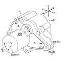
ケーシング3は、オイルポンプ1の外周部を形成しており、その内部には、後述する各構成部材が配置されている。また、ケーシング3は、図1および図2に示すように、その前後中央付近で分割された前ケーシング10および後ケーシング20から構成され、これらは接合面10a、20aで接合しており、ボルト等で前後方向に締結されている。
The
前ケーシング10の上方には、図2に示すように、円形で前後方向に貫通した駆動軸支持孔11が形成されている。一方、前ケーシング10の下方には、接合面10aから前方に向けて円柱状の中空部である前側空間13が形成されており、この前側空間13は、前方側で形成された前端面13bと、円柱状の中空部の側面に相当する内周面13aとによって囲まれた領域である。また、前端面13bにおいて、円形で前後方向に貫通した従動軸支持孔12が形成されている。ここで、前側空間13の中心軸と従動軸支持孔12の中心軸とは同一直線上にあり、さらに、前側空間13および従動軸支持孔12の左右方向中心軸と、駆動軸支持孔11の左右方向中心軸とが、同一直線上にあるように形成されている。さらに、前側空間13に連通して、前端面13bから前方側に延びて、底面7aを有するとともに、内周面13aと同一側面を有した、リング状の中空部であるバネ保持空間7が形成されている。
A drive shaft support hole 11 that is circular and penetrates in the front-rear direction is formed above the
後ケーシング20の上方には、図5に示すように、接合面20aから半円状で後方へ延びた中空部が形成されており、この中空部は、下方および左右方向に開口している。また、この中空部は、その上部が半円面の駆動側内周面2bで囲まれて、後方は駆動側第1側面2cで囲まれて形成されている。さらに、駆動側第1側面2cには、円形で前後方向に貫通した伝達軸支持孔21が形成され、また、伝達軸支持孔21の前端部近傍には、伝達軸支持孔21より大きな径で開口した逃がし21aが形成されている。ここで、伝達軸支持孔21は駆動軸支持孔11よりも大きな径を有している。
As shown in FIG. 5, a hollow portion that is semicircular and extends rearward from the joining surface 20 a is formed above the
後ケーシング20の下方には、図5に示すように、接合面20aから半円状で、後方へ駆動側第1側面2cと同一面まで開口して延びた中空部である、後側空間14が形成されており、さらにこの後側空間14は、上方および左右方向に開口している。また、後側空間14は、その下部が半円面の従動側内周面2fで囲まれており、ここで、従動側内周面2fと前ケーシング10の内周面13aとは、同一径である。さらに、後側空間14の後方側に連通した略リング状の中空部で、円形部分の外側内周面15aおよび下方に湾曲した湾曲面15bによって外周面が形成され、円形の円筒内周面132aで内周面が形成された、ピストン空間15が設けられている。ここで、円筒内周面132aの径は、後述するリング部121の外周面と略同一径となっており、また、従動側内周面2fと外側内周面15aとは略同一径を有して、同一面をなしている。なお、ピストン空間15は、後端部にリング状の底面24を形成している。
Below the
さらに、後ケーシング20の下方には、略リング状のピストン空間15の中心部において、断面視円形の側面23bを外周面として、前後に延びる円柱である、円筒部23が形成されており、前端部である前端面23aは、駆動側第1側面2cよりも後方側で形成されている。さらに、円筒部23の中央部には、前端面23aから後方に向けて、円形の従動軸支持孔22が開口している。ここで、ピストン空間15、従動軸支持孔22および円筒部23は、同一直線上に中心軸を有しており、つまり、図7に示すように、断面視においてこれらは同心円状となっている。さらに、これらの左右方向中心軸と、伝達軸支持孔21の左右方向中心軸とは、同一直線上にある。
Further, below the
駆動側支持軸30は、円柱状で前後方向に延びた軸で、その前端部30aは前ケーシング10の外周面とほぼ同一面をなし、一方、後端部は駆動側第1側面2cまで延びている。伝達軸30cは、円柱状で前後方向に延びた軸で、駆動側支持軸30よりも大きな径を有しており、その前端部は、駆動側第1側面2cまで延び、一方、後端は後ケーシング20の外周面よりも、後方に突出して延びている。従動側支持軸60は、円柱状で前後方向に延びた軸で、回転軸30と略同一径を有しており、その前方部は、従動軸支持孔12の中央付近まで延び、一方、後方部は、従動軸支持孔22の後方底面まで延びている。駆動歯車31は、図5に示すように、その歯先32が前後方向に延びており、また同様に、従動歯車61は、その歯先62が前後方向に延びている。
The drive-
ギヤホルダ110は、前方壁111およびリング後方壁120を主体に構成されている。前方壁111は、その中心部に円形の開口部112を有した略円筒状で、前後方向に延びて形成されており、円筒状の外周面113は内周面13aと略同一径を有し、また、前方壁111の前端面から後方に向けて外周部に、リング状のバネ保持空間114が形成され、バネ保持空間114の後方部は底面114aで形成されている。さらに、前方壁111は、前端面から後方に向けて開口部112と同一中心軸を有した、円柱状の中空部である前面中空部115が形成されている。なお、前方壁111の前方先端部には、リング状の先端部116が形成されているとともに、後方端面には、リング状の後端面111aが形成されている。
The
リング後方壁120は、リング部121とピストン部130とから構成された、1つの構成部品である。リング部121は、円筒状で前後方向に延びて形成されており、図2に示す状態で、前後方向において、前端部は前方壁111の前面中空部115の後端面に位置し、後端部は駆動側第1側面2cと略同一面に位置している。また、リング部121の内周部は、従動側支持軸60と略同一径の円形開口部が形成され、リング部121の外周部は、前方壁111の開口部112と略同一径となっている。
The ring
ピストン部130は、前後方向に延びた略円柱状に形成されており、図2に示す状態で、その前端部である前底面131aは駆動側第1側面2cと略同一面に位置し、後端部はリング状の後底面132cで形成されている。また、その中心部には、リング部121の内周部と連通した、従動側支持軸60と略同一径の円形開口部を有し、また、ピストン部130の断面視略円形の外周面130aは、ピストン空間15の外側内周面15aと略同一径となっている。さらに、ピストン部130の上方外周部では、下方に向けて湾曲した湾曲面132dが形成されており、この湾曲形状は、後ケーシング20の湾曲面15bと略同一形状となっている。
The
さらに、ピストン部130は、断面視中心付近において後底面132cから前方に向かって、円柱状に中空部が形成されており、この中空部は、その外周が断面視略円形の円筒外周面132a、前方がリング状の後底面131bで形成されている。ここで、円筒部23の側面23bと円筒外周面132aとは、略同一径となっている。
Further, the
ピストン部130の内部には、前底面131aと後底面131bとに連通する内部流路133が形成されている。この内部流路133は、図2に示すように、右方向からの側面視において、前方上側から後方下側へと傾斜して形成されるとともに、図6に示すよう前方からの断面視において、上方左側から下方右側へと傾斜して開口している。さらに、内部流路133は、後底面131bの上方端部近傍で開口した先端孔133aと連通している。なお、戻しバネ6は、細長い金属線を螺旋状に巻いて形成されており、金属などの弾性体の復元力を利用し、弾性エネルギーを蓄積する構成となっている。
An
以上、ここまでは、オイルポンプ1の各構成部材について説明したが、以下において、これらの構成部材の組立状態について、図2を参照しながら説明する。 Up to this point, the respective constituent members of the oil pump 1 have been described. Hereinafter, the assembled state of these constituent members will be described with reference to FIG.
駆動側支持軸30は、駆動軸支持孔11に挿入されて回転自在に支持されており、また、伝達軸30cは、伝達軸支持孔21に挿入されて回転自在に支持され、逃がし21aによって、伝達軸30cと伝達軸支持孔21との摺動面積を減らすことができ、よって、摺動抵抗を小さくできる。さらに、これらの軸30、30cの中心軸は同一直線上にあり、駆動側支持軸30の後端部と、伝達軸30cの前端部とは連結されて一体回転する。
The drive-
駆動歯車31は、後ケーシング20の上方で形成された中空部に収容されており、このとき、歯先32が前後方向に直線状に延びるように向けられて、駆動側支持軸30に支持されて固定されており、よって、駆動側支持軸30と一体回転する。また、駆動歯車31は、この状態において、前ケーシング10の接合面10aの一部で、駆動歯車31の前方側面である他側面34と対向する部分に形成された駆動側第2側面2dは、他側面34と略同一平面をなして近接している。同様に、駆動側内周面2bと歯先32とは近接しており、さらに、駆動歯車31の後方側面である一側面33と駆動側第1側面2cとは近接している。ここで、駆動側第2側面2d、駆動側内周面2bおよび駆動側第1側面2cによって囲まれた、半円状の駆動側ポンプ室2aが形成される。なお、駆動側内周面2bと歯先32とは、前後方向に略同一長さで形成されているので、駆動歯車31は、駆動側ポンプ室2a内において、前ケーシング10および後ケーシング20によって前後方向の移動が規制されている。
The
従動側支持軸60は、その前端部60aが従動軸支持孔12に挿入されており、一方、後端部60bが、後ケーシング20に設けられた従動軸支持孔22に圧入されて固定されている。ここで、前ケーシング10と後ケーシング20とを、互いの接合面10a、20aを合わせて組み立てる時に、2箇所に位置決めを設けて、その位置決め同士を合わせるようにして組み立てることで、上下左右方向に正確な位置で接合されるように構成されている。このとき一方の位置決めは、接合面10a、20aのそれぞれ対向する位置にノックピン穴(図示せず)を開けて、そこにノックピンを挿入して構成されている。また、他方の位置決めは、従動軸支持孔12に従動側支持軸60を挿入することで位置決めとなるように構成されている。つまり、従動軸支持孔12は、従動側支持軸60に対してわずかに大きく形成されており、前ケーシング10と後ケーシング20との組み立て時には、従動側支持軸60の前端部60aを挿入することで位置決めとなり、また組み立て後には、挿入された従動側支持軸60の前端部60aを支持している。ギヤホルダ110は、リング部121の外周部に、従動歯車61を回転自在に支持させた状態で、前方壁111の開口部112に、リング部121の前端部を後方から圧入して固定することで、前方壁111、リング後方壁120および従動歯車61が、一体となることによって形成されている。また、ギヤホルダ110の中心開口部には、従動側支持軸60が摺動自在に挿入されている。
The driven-
このとき、従動歯車61の前方側面である他側面64と、前方壁111の後端面111aとは、略同一平面をなして近接している。また、同様に、従動歯車61の前後方向に直線状に延びた歯先62と従動側内周面2fとは近接しており、従動歯車61の後方側面である一側面63と前底面131aとは近接している。また、従動歯車61と駆動歯車31とは、上下中央付近で噛合している。ここで、後端面111a、従動側内周面2fおよび前底面131aによって囲まれた、半円状の従動側ポンプ室2eが形成され、さらに、従動側ポンプ室2e上方は、駆動側ポンプ室2aと連通しており、これら従動側ポンプ室2eと駆動側ポンプ室2aとをまとめてポンプ室2と呼ぶ。ここで、ポンプ室2は、左右方向に開口しており、図1に示すように右側に連通した吸込ポート4、左側に連通した吐出ポート5が形成されている。
At this time, the
ピストン部130は、そのピストン部130の湾曲面132dと後ケーシング20の湾曲面15bとを合わせて、ピストン空間15に対して、前方から後方へと挿入されている。このとき、湾曲面132dと湾曲面15b、外周面130aと外側内周面15aとは、それぞれ近接しており、よって、ピストン部130は、ピストン空間15内を軸方向に摺動自在となっている。ここで、湾曲面132dは、駆動歯車31が回転したときの歯先32の回転軌道と略同一となっている。さらに、前方壁111は、前ケーシング10の前側空間13に後方から前方へと挿入され、外周面113と内周面13aとが近接しており、よって、前方壁111は、前側空間13内を軸方向に摺動自在となっている。なお、内周面13aと従動側内周面2fとは、同一面なしており、よって、従動歯車61の歯先62と内周面13aとは近接する。
The
ギヤホルダ110は、湾曲面132dと湾曲面15bとが嵌合状態となっているために、従動側支持軸60を中心とした回転が規制された状態で、軸方向に摺動自在となっている。さらにこのとき、従動側支持軸60の中心軸は、駆動側支持軸30および伝達軸30cの中心軸と平行で、かつこれらの左右位置は一致している。また、従動側支持軸60の中心軸は、ギヤホルダ110および円筒部23の各中心軸と、同一直線上にある。
Since the
また、戻しバネ6が、ギヤホルダ110よりも前方の前側空間13において、前後方向に伸縮可能となる向きに設置されている。戻しバネ6の後端6aは、バネ保持空間114に収容保持されて、底面114aと当接しており、一方、戻しバネ6の前端6bは、バネ保持空間7に収容保持されて、底面7aと当接している。ここで、戻しバネ6は、ギヤホルダ110に対して、後方側へ付勢力を作用させており、よって、ギヤホルダ110は後方軸方向へ摺動し、後底面132cが底面24に当接した位置で静止し、このとき、後底面131b、円筒外周面132aおよび前端面23aによって囲まれた、リング状の閉塞空間25が形成される。なお、この静止状態においても、戻しバネ6は、ギヤホルダ110に対して、後方側へ一定の付勢力を作用させている。
Further, the
以上、各構成部材の組立状態について説明してきたが、以下においては、オイルポンプ1が稼動を開始したときの、各構成部材の動作について、図1から図9を参照しながら説明する。なお、図2に示す状態を初期状態と定義する。 The assembly state of each component has been described above. Hereinafter, the operation of each component when the oil pump 1 starts operation will be described with reference to FIGS. 1 to 9. The state shown in FIG. 2 is defined as the initial state.
エンジンが始動してアイドリング状態となると、図2に示すように、伝達軸30cおよび伝達軸30cに連結された駆動側支持軸30が回転駆動し、噛合した両歯車31,61が回転することで、タンクに溜められたオイルが、吸入口4aから吸込ポート4に吸い込まれ、ポンプ室2を経由して吐出ポート5に送られて、吐出口5aから潤滑油路に圧送される。なお、潤滑油路は、エンジンケースに形成されており、供給油量の増加に応じて供給油圧を上昇させる構成となっている。
When the engine is started and is in an idling state, as shown in FIG. 2, the drive-
このとき、図1に示すように、駆動歯車31は方向Aの向きに回転することによって、駆動側ポンプ室2aと駆動歯車31との隙間に流入したオイルが、吸込ポート4から吐出ポート5に搬送される。一方、従動歯車61は方向Bの向きに回転することによって、従動側ポンプ室2eと従動歯車61との隙間に流入したオイルが、吸込ポート4から吐出ポート5に搬送される。なお、吐出ポート5においては、オイルは高圧となっているため、吐出ポート5で駆動歯車31と従動歯車61とが噛合することで、互いの歯と歯との間に挟まれたオイルを吐出ポート5に排出し、オイルを吸入ポート4から吐出ポート5に搬送可能となる。
At this time, as shown in FIG. 1, the
また、このとき、吐出ポート5に吐出されたオイルの一部は、内部流路133を介して、閉塞空間25に供給される。そして、閉塞空間25に供給されたオイルの油圧が、後底面131bに対して前方に作用し、ギヤホルダ110は、付勢力に抗する押圧力を前方軸方向に受ける。ここで、初期状態においては、付勢力を上回る押圧力が発生しておらず、押圧力は付勢力によって打ち消され、ギヤホルダ110は、付勢力によってその後底面132cが底面24に当接した状態で静止している。
At this time, part of the oil discharged to the
図9には、エンジンがアイドリング時の、ポンプ回転数Niを示しているが、オイルポンプ1の作動時には、この回転数Niを下回ることはほとんどなく、このときの吐出流量Qiは、潤滑に必要とされる供給油量を確保可能になっている。このアイドリング時の、駆動歯車31および従動歯車61の噛み合い幅δを、最大噛み合い幅δMと称し、図2に示す初期状態においては、両歯車31,61が最大噛み合い幅δMで噛合している。
FIG. 9 shows the pump rotational speed Ni when the engine is idling. However, when the oil pump 1 is operated, the rotational speed Ni is rarely below, and the discharge flow rate Qi at this time is necessary for lubrication. The amount of oil supplied can be secured. This idling, the mesh width [delta] of the
次に、エンジンの出力が高くなって、ポンプ回転数Nが第1回転数NAに達すると、吐出ポート5での油圧が高まり、それに伴って、閉塞空間25に供給されるオイルの油圧も高まって、よって、アイドリング時よりも大きな押圧力が、ギヤホルダ110に作用する。そして、ギヤホルダ110に作用する押圧力と付勢力とが、軸方向において、ほぼ釣り合う状態になる。
Next, when the output of the engine increases and the pump rotational speed N reaches the first rotational speed N A , the hydraulic pressure at the
そして、ポンプ回転数Nが第1回転数NAを越えると、押圧力が付勢力を上回り、ギヤホルダ110は、付勢力に抗して前方軸方向に摺動してバネ6を圧縮させて、押圧力が付勢力と釣り合う位置まで摺動し、両歯車31,61の噛み合い幅δは短くなる。このとき、ピストン部130の上部は、駆動歯車31の回転軌道領域内に移動してくるが、湾曲面132dは、歯先32の回転軌道と略同一となるように下方に湾曲しているので、湾曲面132dと歯先32とは干渉しない。この状態において、駆動歯車31と従動歯車61とが、噛み合っていない領域が形成されるが、この領域に流入したオイルは、吐出ポート5で排出されず、歯と歯との間に留まったままの状態となり、よって、アイドリング時と比較してポンプ容量は低下する。
When the pump rotational speed N exceeds the first rotational speed N A, it exceeds the biasing force pressing force, the
しかし、図9に示すように、ポンプ回転数Nの増加と、ポンプ回転数Nが増加して噛み合い幅δが短くなって生じるポンプ容量の低下とのバランスにより、結果として、ポンプ回転数Nの増減に関わらず吐出流量Qが、安定するように構成されている。これにより、エンジンの出力が高くなっても、オイルポンプ1から過剰なオイルが吐出されない。 However, as shown in FIG. 9, due to the balance between the increase in the pump rotational speed N and the decrease in pump capacity that occurs when the pump rotational speed N increases and the meshing width δ decreases, the pump rotational speed N The discharge flow rate Q is configured to be stable regardless of increase / decrease. Thereby, even if the output of the engine increases, excessive oil is not discharged from the oil pump 1.
次に、ポンプ回転数Nが、第2回転数NBに達すると、押圧力がさらに大きくなり、ギヤホルダ110は、付勢力に抗してさらに前方軸方向に摺動してバネ6を圧縮させて、図8に示すように、ギヤホルダ110の前端部116が、前側空間13の前端面13bに当接して静止する。ここで、ポンプ回転数Nが第2回転数NBを越えても、ギヤホルダ110は、前方軸方向への移動が規制されるため、噛み合い幅δが、このときの噛み合い幅δmよりも短くなることはない。よって、このときの噛み合い幅δmを最小噛み合い幅と呼ぶ。
Then, the pump rotational speed N reaches a second rotational speed N B, the pressing force is further increased, the
よって、ポンプ回転数Nが、第1回転数NAおよび第2回転数NBの間にあるとき、ギヤホルダ110は、軸方向の移動が規制されることなく、前側空間13内において、押圧力および付勢力の釣り合いによって、所定位置に移動して停止する。このとき、付勢力および押圧力は、ギヤホルダ110に対して、互いに反対方向から作用することで打ち消し合うため、従動側支持軸60には、付勢力や押圧力に応じた負荷が作用せず、よって、ギヤホルダ110が、上下または左右方向に移動するようなことがない。
Therefore, when the pump rotational speed N is between the first rotational speed N A and second rotational speed N B, the
以下に、本発明に係るオイルポンプ1の効果をまとめてみると、第1に、ギヤホルダ110を、断面視において従動側支持軸60と同心円状に形成することで、従動側支持軸60を中心として、ギヤホルダ110を小型化可能となり、よって、オイルポンプ1を小型化可能となる。さらに、ギヤホルダ110の小型化によって、ギヤホルダ110の軸方向への摺動に要する押圧力が小さくなるので、押圧力に抗する付勢力も小さくでき、よって、戻しバネ6を、小型のものを用いることが可能となり、オイルポンプ1をさらに小型化可能となる。
Hereinafter, the effects of the oil pump 1 according to the present invention will be summarized. First, the
第2に、断面視において、従動側支持軸60と同心円でリング状の狭小な閉塞空間25にオイルを導くことで、必要な押圧力を得る構成とすることで、ギヤホルダ110に対して押圧力をバランス良く軸方向に作用させることが可能となり、よって、噛み合い幅δの変更を円滑に行うことができる。
Secondly, in a cross-sectional view, oil is guided to the ring-shaped narrow
第3に、ギヤホルダ110は、リング部121の外周部に、従動歯車61を回転自在に支持させた状態で、前方壁111の開口部112に、リング部121の前端部を後方から圧入して固定することで、前方壁111、リング後方壁120および従動歯車61が、一体となることによって形成されている。よって、従動側ポンプ室2eの、従動側第1側面2gと従動側第2側面2hとの対向間隔が変化することがないので、例えば、対向間隔が大きくなることでオイルが漏出したり、一方で、対向間隔が小さくなることで、摺動抵抗が増大することもないので、オイルポンプ1の作動効率を維持することが容易となる。
Third, the
第4に、吐出油圧を閉塞空間25の後底面131bに、押圧力として作用させるとともに、戻しバネ6の付勢力を、ギヤホルダ110に作用させることで、従動歯車61を軸方向に移動可能に構成している。これにより、吐出油圧を用いたポンプ容量の可変制御が行われ、ポンプ回転数Nの増減に関わらず、吐出流量Qを安定させる制御を簡単に行うことができるようになる。
Fourth, the discharge hydraulic pressure is applied to the
第5に、この可変制御を行わせるために、ピストン部130内部に、吐出ポート5と閉塞空間25とを連通する内部流路133が形成されている。この内部流路133は、ピストン部130の内部にのみ形成すれば良いので、内部流路133の形成を簡単に行うことができる。よって、複数部材間に跨って形成されるときに必要とされる、シール構造の省略も図られ、オイルポンプ1の製作コストを低減することが可能となる。第6に、従来のオイルポンプにおいて、前ケーシング10と後ケーシング20とを組み立てる時に、2箇所にノックピン穴を開けてノックピンを挿入することで位置決めを構成していたが、本発明では従動軸支持孔12に従動側支持軸60を挿入する構成を位置決めとして利用することで、2箇所のうち1箇所のノックピン穴加工およびノックピンが不要となる。よって、オイルポンプ1の製作時の作業工数を減らすことができるとともに、製作コストを低減することが可能となる。
Fifth, in order to perform this variable control, an
1 オイルポンプ(ギヤポンプ)
2 ポンプ室(配設空間)
3 ケーシング
4 吸入ポート
5 吐出ポート
6 付勢部材(戻しバネ)
25 閉塞空間
30 駆動側支持軸(第1支持軸)
31 駆動歯車(第1ギヤ)
60 従動側支持軸(第2支持軸)
61 従動歯車(第2ギヤ)
110 ギヤホルダ
111 前方壁(他方側壁)
120 リング後方壁(一方側壁)
121 リング部(軸部)
130 ピストン部(ピストン)
133 内部流路
1 Oil pump (gear pump)
2 Pump room (arrangement space)
3
25
31 Drive gear (first gear)
60 Driven support shaft (second support shaft)
61 Driven gear (second gear)
110 Gear holder 111 Front wall (other side wall)
120 Ring rear wall (one side wall)
121 Ring (shaft)
130 Piston part (piston)
133 Internal flow path
Claims (3)
前記第1支持軸と平行に配設された第2支持軸に回転自在に支持されて前記第1ギヤと噛合する第2ギヤと、
前記第1支持軸を回転自在に支持し前記第2支持軸を支持するとともに、前記第1ギヤおよび前記第2ギヤを収容する配設空間を備えたケーシングとからなり、
前記ケーシングに、前記配設空間と連通する吸込ポートおよび前記配設空間と連通する吐出ポートが形成されて、
前記第1支持軸が回転して前記第1ギヤと前記第2ギヤとが噛合した状態で回転することで、流体が前記吸込ポートに吸い込まれて前記吐出ポートから吐出されるギヤポンプにおいて、
前記配設空間に、前記第2ギヤを回転自在に支持するとともに前記第2ギヤの両側面を挟持して、前記第2支持軸に支持されて支持軸方向に移動自在に設けられたギヤホルダを有し、
前記ギヤホルダは、支持軸方向の一端側に付勢する付勢部材からの付勢力を受けるとともに、前記付勢力に抗して支持軸方向の他端側に押圧する押圧力を受けて、前記第2ギヤを保持した状態で支持軸方向に移動することを特徴とするギヤポンプ。 A first gear fixed to a first support shaft extending in the left-right direction and rotating together with the first support shaft;
A second gear rotatably supported on a second support shaft disposed in parallel with the first support shaft and meshing with the first gear;
The first support shaft is rotatably supported to support the second support shaft, and includes a casing having an arrangement space for housing the first gear and the second gear.
In the casing, a suction port communicating with the arrangement space and a discharge port communicating with the arrangement space are formed,
In the gear pump in which the first support shaft rotates and rotates in a state where the first gear and the second gear mesh with each other, fluid is sucked into the suction port and discharged from the discharge port.
A gear holder that rotatably supports the second gear and sandwiches both side surfaces of the second gear in the arrangement space and is supported by the second support shaft and is movable in the direction of the support shaft. Have
The gear holder receives an urging force from an urging member that urges toward one end side in the support shaft direction, and receives a pressing force against the urging force toward the other end side in the support shaft direction. A gear pump that moves in the direction of the support shaft while holding two gears.
前記軸部に前記第2ギヤが回転自在に支持されて、前記一方側壁の一側面が前記第2ギヤの一側面と近接するとともに、前記他方側壁の一側面が前記第2ギヤの他側面と近接し、
前記一方側壁の他側面もしくは前記他方側壁の他側面に、前記押圧力を受けるピストンが形成されていることを特徴とする請求項1に記載のギヤポンプ。 The gear holder is composed of one side wall provided with a ring-shaped shaft part and a columnar side wall part and the other side wall of the columnar shape,
The second gear is rotatably supported by the shaft portion, and one side surface of the one side wall is close to one side surface of the second gear, and one side surface of the other side wall is the other side surface of the second gear. Close
The gear pump according to claim 1, wherein a piston that receives the pressing force is formed on the other side surface of the one side wall or the other side surface of the other side wall.
前記ピストンは、前記内部流路を介して前記閉塞空間に供給された流体圧により前記押圧力を受けるように構成されることを特徴とする請求項2に記載のギヤポンプ。 The gear holder is formed with an internal flow path that communicates the discharge port and a closed space formed on the back side of the piston,
The gear pump according to claim 2 , wherein the piston is configured to receive the pressing force by a fluid pressure supplied to the closed space through the internal flow path.
Priority Applications (5)
| Application Number | Priority Date | Filing Date | Title |
|---|---|---|---|
| JP2007133683A JP5064886B2 (en) | 2007-05-21 | 2007-05-21 | Gear pump |
| PCT/JP2007/065975 WO2008142806A1 (en) | 2007-05-21 | 2007-08-10 | Gear pump |
| EP07792605.3A EP2154373B1 (en) | 2007-05-21 | 2007-08-10 | Gear pump |
| US12/596,766 US8376724B2 (en) | 2007-05-21 | 2007-08-10 | Gear pump enabling efficient pump capacity change |
| CN2007800530256A CN101675247B (en) | 2007-05-21 | 2007-08-10 | Gear pump |
Applications Claiming Priority (1)
| Application Number | Priority Date | Filing Date | Title |
|---|---|---|---|
| JP2007133683A JP5064886B2 (en) | 2007-05-21 | 2007-05-21 | Gear pump |
Publications (3)
| Publication Number | Publication Date |
|---|---|
| JP2008286147A JP2008286147A (en) | 2008-11-27 |
| JP2008286147A5 JP2008286147A5 (en) | 2010-06-17 |
| JP5064886B2 true JP5064886B2 (en) | 2012-10-31 |
Family
ID=40031531
Family Applications (1)
| Application Number | Title | Priority Date | Filing Date |
|---|---|---|---|
| JP2007133683A Active JP5064886B2 (en) | 2007-05-21 | 2007-05-21 | Gear pump |
Country Status (5)
| Country | Link |
|---|---|
| US (1) | US8376724B2 (en) |
| EP (1) | EP2154373B1 (en) |
| JP (1) | JP5064886B2 (en) |
| CN (1) | CN101675247B (en) |
| WO (1) | WO2008142806A1 (en) |
Families Citing this family (13)
| Publication number | Priority date | Publication date | Assignee | Title |
|---|---|---|---|---|
| DE102011010835B4 (en) * | 2011-02-10 | 2014-01-30 | Audi Ag | displacement |
| DE102011013756A1 (en) * | 2011-03-12 | 2012-09-13 | Volkswagen Aktiengesellschaft | Gear pump, particularly oil pump for internal combustion engine, has control valve, which is additionally connected with outlet over throttle in position of piston for connecting control fluid in fluid conducting manner |
| JP5670793B2 (en) * | 2011-03-27 | 2015-02-18 | 株式会社山田製作所 | Pump device |
| DE102013001750A1 (en) | 2013-01-31 | 2014-07-31 | Volkswagen Aktiengesellschaft | Method for controlling oil pressure for combustion engine, involves keeping oil pressure in first speed range of engine constant and increasing oil pressure in second speed range with increasing speed so as to be above first speed range |
| KR20140140011A (en) * | 2013-05-03 | 2014-12-08 | 장순길 | Variable displacement gear pump |
| CN106068087B (en) * | 2014-01-03 | 2020-03-03 | 皇家戴维艾格伯茨有限公司 | Exchangeable supply pack for a beverage dispensing machine, dispenser, pump assembly and method of manufacturing |
| KR102003107B1 (en) | 2015-08-12 | 2019-07-24 | 장순길 | Variable displacement pump |
| WO2017026639A1 (en) * | 2015-08-12 | 2017-02-16 | 장순길 | Variable displacement gear pump |
| US10309396B2 (en) | 2016-04-27 | 2019-06-04 | Deere & Company | Positive displacement pump including an unloading device |
| US10113546B2 (en) * | 2016-08-16 | 2018-10-30 | Caterpillar Inc. | Pump for an engine |
| CN108150410A (en) * | 2017-12-27 | 2018-06-12 | 郑州沃华机械有限公司 | A kind of smelt gear pump dedicated for rubber production device |
| JP7070174B2 (en) * | 2018-07-06 | 2022-05-18 | トヨタ自動車株式会社 | Vehicle power transmission device |
| CN108953576A (en) * | 2018-09-27 | 2018-12-07 | 湖南机油泵股份有限公司 | A kind of transmission oil pump being avoided that eccentric wear |
Family Cites Families (17)
| Publication number | Priority date | Publication date | Assignee | Title |
|---|---|---|---|---|
| DE511495C (en) * | 1928-03-01 | 1930-10-30 | Valentin Retterath | Fluid transmission |
| US2262331A (en) * | 1940-12-05 | 1941-11-11 | Bendix Aviat Corp | Fluid pressure system |
| US2684636A (en) * | 1949-12-05 | 1954-07-27 | Arthur P Heldenbrand | Variable capacity gear pump |
| DE1553234A1 (en) * | 1965-06-25 | 1970-03-19 | Tuchenhagen Otto | Adjustable gear pump |
| US3446118A (en) * | 1966-10-28 | 1969-05-27 | Tozaburo Kuhara | Variable torque hydraulic gear motor |
| JPS5773880A (en) | 1980-10-23 | 1982-05-08 | Nissan Motor Co Ltd | Variable capacity gear pump |
| DE3528651A1 (en) * | 1985-08-09 | 1987-02-19 | Rohs Hans Guenther Prof Dr Ing | GEAR PUMP |
| DE4121074A1 (en) * | 1991-06-26 | 1993-01-07 | Pierburg Gmbh | External gear pump - has main drive gear fixed inside housing and driven gear adjusted by pressure differential piston action |
| US5306127A (en) * | 1993-03-08 | 1994-04-26 | Kinney Gerald R | Fluid pump with axially adjustable gears |
| FR2711739B1 (en) * | 1993-10-26 | 1995-11-24 | Renault | Lubrication pump for internal combustion engine. |
| DE19847132C2 (en) * | 1998-10-13 | 2001-05-31 | Schwaebische Huettenwerke Gmbh | External gear pump with delivery volume limitation |
| DE10043842A1 (en) * | 2000-03-02 | 2001-09-06 | Volkswagen Ag | Gear pump with a displacement unit that changes the delivery rate |
| DE10033950C2 (en) * | 2000-07-13 | 2003-02-27 | Schwaebische Huettenwerke Gmbh | Pump with magnetic coupling |
| DE102004002062A1 (en) * | 2004-01-15 | 2005-08-04 | Volkswagen Ag | Gear pump with flow control |
| DE102005029086B4 (en) * | 2005-06-23 | 2016-06-16 | Dr. Ing. H.C. F. Porsche Aktiengesellschaft | Oil pump for an internal combustion engine |
| DE102006018124A1 (en) * | 2006-04-19 | 2007-10-25 | Schwäbische Hüttenwerke Automotive GmbH & Co. KG | Adjustable rotary pump with wear reduction |
| US7717690B2 (en) | 2006-08-15 | 2010-05-18 | Tbk Co., Ltd. | Gear pump |
-
2007
- 2007-05-21 JP JP2007133683A patent/JP5064886B2/en active Active
- 2007-08-10 EP EP07792605.3A patent/EP2154373B1/en active Active
- 2007-08-10 US US12/596,766 patent/US8376724B2/en active Active
- 2007-08-10 CN CN2007800530256A patent/CN101675247B/en not_active Expired - Fee Related
- 2007-08-10 WO PCT/JP2007/065975 patent/WO2008142806A1/en active Application Filing
Also Published As
| Publication number | Publication date |
|---|---|
| WO2008142806A1 (en) | 2008-11-27 |
| EP2154373A1 (en) | 2010-02-17 |
| JP2008286147A (en) | 2008-11-27 |
| US20100086422A1 (en) | 2010-04-08 |
| EP2154373B1 (en) | 2019-10-09 |
| EP2154373A4 (en) | 2017-03-01 |
| US8376724B2 (en) | 2013-02-19 |
| CN101675247B (en) | 2013-04-24 |
| CN101675247A (en) | 2010-03-17 |
Similar Documents
| Publication | Publication Date | Title |
|---|---|---|
| JP5064886B2 (en) | Gear pump | |
| JP5084536B2 (en) | Oil pump | |
| JP4829957B2 (en) | Gear pump | |
| JP5116546B2 (en) | Variable displacement vane pump | |
| EP2034205A1 (en) | Hydraulic mechanism for vehicle | |
| JP2007170321A (en) | Variable displacement vane pump | |
| US20150354564A1 (en) | Oil pump | |
| JP5357123B2 (en) | Pump device, power steering device, and housing assembly method | |
| JP5007085B2 (en) | Tandem pump valve structure | |
| US7717690B2 (en) | Gear pump | |
| JP5014841B2 (en) | Variable displacement pump | |
| JP6171852B2 (en) | Oil pump device | |
| JP2008025423A (en) | Variable displacement pump | |
| JP6264850B2 (en) | Oil pump device and relief valve | |
| JP5478453B2 (en) | Hydraulic device | |
| JP2008001251A (en) | Pump device and power steering device applied with pump device | |
| JP2021167606A (en) | Variable capacity-type oil pump | |
| JP5510360B2 (en) | Vehicle transmission | |
| JP5230971B2 (en) | Gear pump | |
| JP3501990B2 (en) | Variable displacement pump | |
| JP5009732B2 (en) | Internal gear pump | |
| JP2020041522A (en) | Variable displacement pump | |
| JP2000161246A (en) | Oil pump | |
| JP2015132199A (en) | pump device | |
| JP2002089709A (en) | Check valve of hydraulic continuously variable transmission |
Legal Events
| Date | Code | Title | Description |
|---|---|---|---|
| A521 | Request for written amendment filed |
Free format text: JAPANESE INTERMEDIATE CODE: A523 Effective date: 20100426 |
|
| A621 | Written request for application examination |
Free format text: JAPANESE INTERMEDIATE CODE: A621 Effective date: 20100426 |
|
| TRDD | Decision of grant or rejection written | ||
| A01 | Written decision to grant a patent or to grant a registration (utility model) |
Free format text: JAPANESE INTERMEDIATE CODE: A01 Effective date: 20120727 |
|
| A01 | Written decision to grant a patent or to grant a registration (utility model) |
Free format text: JAPANESE INTERMEDIATE CODE: A01 |
|
| A61 | First payment of annual fees (during grant procedure) |
Free format text: JAPANESE INTERMEDIATE CODE: A61 Effective date: 20120809 |
|
| R150 | Certificate of patent or registration of utility model |
Ref document number: 5064886 Country of ref document: JP Free format text: JAPANESE INTERMEDIATE CODE: R150 Free format text: JAPANESE INTERMEDIATE CODE: R150 |
|
| FPAY | Renewal fee payment (event date is renewal date of database) |
Free format text: PAYMENT UNTIL: 20150817 Year of fee payment: 3 |
|
| R250 | Receipt of annual fees |
Free format text: JAPANESE INTERMEDIATE CODE: R250 |
|
| R250 | Receipt of annual fees |
Free format text: JAPANESE INTERMEDIATE CODE: R250 |
|
| R250 | Receipt of annual fees |
Free format text: JAPANESE INTERMEDIATE CODE: R250 |
|
| R250 | Receipt of annual fees |
Free format text: JAPANESE INTERMEDIATE CODE: R250 |
|
| R250 | Receipt of annual fees |
Free format text: JAPANESE INTERMEDIATE CODE: R250 |
|
| R250 | Receipt of annual fees |
Free format text: JAPANESE INTERMEDIATE CODE: R250 |
|
| R250 | Receipt of annual fees |
Free format text: JAPANESE INTERMEDIATE CODE: R250 |
|
| R250 | Receipt of annual fees |
Free format text: JAPANESE INTERMEDIATE CODE: R250 |
|
| R250 | Receipt of annual fees |
Free format text: JAPANESE INTERMEDIATE CODE: R250 |