JP5056428B2 - Digital camera - Google Patents

Digital camera Download PDF

Info

Publication number
JP5056428B2
JP5056428B2 JP2008006157A JP2008006157A JP5056428B2 JP 5056428 B2 JP5056428 B2 JP 5056428B2 JP 2008006157 A JP2008006157 A JP 2008006157A JP 2008006157 A JP2008006157 A JP 2008006157A JP 5056428 B2 JP5056428 B2 JP 5056428B2
Authority
JP
Japan
Prior art keywords
imaging
optical system
unit
microlens array
lens
Prior art date
Legal status (The legal status is an assumption and is not a legal conclusion. Google has not performed a legal analysis and makes no representation as to the accuracy of the status listed.)
Expired - Fee Related
Application number
JP2008006157A
Other languages
Japanese (ja)
Other versions
JP2009169025A (en
JP2009169025A5 (en
Inventor
健二 山本
Current Assignee (The listed assignees may be inaccurate. Google has not performed a legal analysis and makes no representation or warranty as to the accuracy of the list.)
Sony Corp
Original Assignee
Sony Corp
Priority date (The priority date is an assumption and is not a legal conclusion. Google has not performed a legal analysis and makes no representation as to the accuracy of the date listed.)
Filing date
Publication date
Application filed by Sony Corp filed Critical Sony Corp
Priority to JP2008006157A priority Critical patent/JP5056428B2/en
Publication of JP2009169025A publication Critical patent/JP2009169025A/en
Publication of JP2009169025A5 publication Critical patent/JP2009169025A5/ja
Application granted granted Critical
Publication of JP5056428B2 publication Critical patent/JP5056428B2/en
Expired - Fee Related legal-status Critical Current
Anticipated expiration legal-status Critical

Links

Images

Description

本発明は、マイクロレンズアレイを用いた撮像装置を備えたデジタルカメラに関する。 The present invention relates to a digital camera having an imaging equipment using a microlens array.

従来、一眼レフレックス(一眼レフ)デジタルカメラにおいて、撮影レンズの後方に配置された撮像素子により撮像される画像をリアルタイムに画像表示用LCD(Liquid Crystal Display)へ映し出すライブビュー表示(スルー表示)を可能にする方法が提案されている。例えば特許文献1には、可動ミラーを撮影光学系の光路から退避させると共に撮像素子の前面に配置されたシャッタを開放状態にした状態で、被写体像を撮像素子に投影させることにより、その映像を画像表示用LCDに表示するようにしたデジタルカメラが提案されている。なお、このデジタルカメラでは、ライブビュー表示状態において、光学ファインダは使えない状態になっている。   Conventionally, in a single-lens reflex (single-lens reflex) digital camera, live view display (through display) that displays an image captured by an image sensor placed behind the taking lens on an image display LCD (Liquid Crystal Display) in real time Proposals have been made to make this possible. For example, in Patent Document 1, a moving mirror is retracted from an optical path of a photographing optical system, and a subject image is projected on an image pickup device in a state where a shutter disposed in front of the image pickup device is opened. There has been proposed a digital camera configured to display on an image display LCD. In this digital camera, the optical viewfinder cannot be used in the live view display state.

また、例えば特許文献2には、一眼レフデジタルカメラにおいてハーフミラーで構成された可動ミラーを用いることにより、被写体像の観察モードとして、光学ファインダによる観察モード(ファインダ観察モード)と、画像表示用LCDを用いた観察モード(ライブビュー表示モード)とを切り換え可能にしたものが開示されている。このデジタルカメラでは、ライブビュー表示モード時、可動ミラーが撮影光学系の光路から退避されるようになっている。   Further, for example, in Patent Document 2, by using a movable mirror composed of a half mirror in a single-lens reflex digital camera, an observation mode by using an optical finder (finder observation mode) and an image display LCD are used as object image observation modes. Is disclosed which can be switched between an observation mode (live view display mode) using. In this digital camera, the movable mirror is retracted from the optical path of the photographing optical system in the live view display mode.

なお、このようなライブビュー表示モードについては、他にも例えば特許文献3などにも開示されている。   Such a live view display mode is also disclosed in, for example, Patent Document 3 and the like.

特開2001−272593号公報JP 2001-272593 A 特開2001−186401号公報JP 2001-186401 A 特開2007−142868JP2007-142868

しかしながら、上述した特許文献1および特許文献2に開示されたデジタルカメラでは、ライブビュー表示モードのもとでのAF(合焦)動作時に、上記のように測距用の光路を持てないため、いわゆる位相差AFを利用することができない。したがって、撮像素子で取り込まれた画像情報を用いたコントラスト方式による合焦動作となる。ところが、このコントラスト方式による合焦動作では合焦速度が遅くなるため、従来のレンズ交換式の一眼レフカメラの持ち味である、タイムラグが少ないという利点が著しく損なわれてしまうことになる。   However, since the digital cameras disclosed in Patent Document 1 and Patent Document 2 described above cannot have an optical path for distance measurement as described above during AF (focusing) operation under the live view display mode, So-called phase difference AF cannot be used. Therefore, the focusing operation is performed by the contrast method using the image information captured by the image sensor. However, since the focusing speed is reduced in the focusing operation by this contrast method, the advantage of a small time lag, which is a characteristic of a conventional interchangeable lens single-lens reflex camera, is significantly impaired.

また、上述した特許文献3に開示されたデジタルカメラでは、ライブビュー表示時と測距時との間でミラーの切り替えが必要となるため、振動が生じてしまうなどの問題があった。   In addition, the digital camera disclosed in Patent Document 3 described above has a problem in that vibration is generated because the mirror needs to be switched between live view display and distance measurement.

なお、銀塩式一眼レフカメラでは、クイックリターンミラー(可動ミラー)の代わりにペリクル薄膜固定式ハーフミラーを用いることにより、被写体光線を、光学ファインダ側とフィルム側とへ分離して導くようにしたものが提案されている。この銀塩式一眼レフカメラによれば、クイックミラーの動作時間を削ることができるため、AF導光ミラーおよびシャッタ動作のみの機構により、高速速写が可能となる。   The silver halide single-lens reflex camera uses a pellicle thin film fixed half mirror instead of a quick return mirror (movable mirror) to separate and direct the subject light beam to the optical viewfinder side and film side. Things have been proposed. According to this silver salt type single-lens reflex camera, since the operation time of the quick mirror can be reduced, high-speed shooting can be performed by the mechanism only with the AF light guide mirror and the shutter operation.

そこで、この方式をデジタルカメラに適用する場合を考えると、ペリクル薄膜固定式ハーフミラーを用いて被写体光線を透過光線と反射光線とに分離し、一方の光線を位相差AFに利用すると共に他方の光線を撮像素子に導くようにすれば、常時開状態のシャッタを用いることにより、ライブビュー表示モードによるリアルタイムの画像表示を実現しつつ、合焦動作時に位相差AFの利用が可能となる。   Therefore, when considering the case where this method is applied to a digital camera, a subject light beam is separated into a transmitted light beam and a reflected light beam using a pellicle thin film fixed half mirror, and one light beam is used for phase difference AF and the other is used. If the light beam is guided to the image sensor, the phase difference AF can be used during the focusing operation while realizing the real-time image display in the live view display mode by using the normally open shutter.

しかしながら、この構成(ハーフミラーを用いた構成)では光学ファインダによる観測(ファインダ観察モード)時、ライブビュー表示機能を使用していないときでも光学ファインダ側への入射光量が落ちてしまうことから、光学ファインダから観察する被写体像が暗くなり、使いにくい場合が生じる。   However, in this configuration (configuration using a half mirror), the amount of light incident on the optical viewfinder is reduced even when the live view display function is not used during observation with the optical viewfinder (finder observation mode). The subject image observed from the viewfinder may become dark and difficult to use.

本発明はかかる問題点に鑑みてなされたもので、その目的は、ライブビュー表示モードを利用した撮像モード(ライブビュー撮像モード)が利用可能であり、ライブビュー撮像モードの際の高速な合焦動作を実現しつつ利便性を向上させることが可能なデジタルカメラを提供することにある。 The present invention has been made in view of such a problem, and an object thereof is to use an imaging mode (live view imaging mode) using a live view display mode, and to perform high-speed focusing in the live view imaging mode. and to provide a digital camera capable of improving the convenience while realizing the operation.

発明のデジタルカメラは、撮像光学系を含んで構成された撮像装置と、この撮像装置により得られる撮像データに基づき、被写体の撮像画像を表示する表示手段とを備えたものである。上記撮像装置は、撮像光学系からの被写体像を観察するための観察光学系と、撮像光学系としての撮像レンズおよびマイクロレンズアレイ部と、受光した光に基づいて撮像データを取得する撮像素子と、撮像素子により得られた撮像データに基づいて画像処理を行うことにより、撮像レンズの合焦動作の際の撮像レンズの駆動距離を算出する測距動作を行う第1の測距手段と、観察光学系を利用して位相差AFによる測距動作を行う第2の測距手段と、第1または第2の測距手段により算出された駆動距離を用いて合焦動作を行う合焦手段と、第1の測距手段を利用した合焦動作の際には、マイクロレンズアレイ部による撮像光学系としての機能を発揮させる一方、撮像動作の際には、マイクロレンズアレイ部による撮像光学系としての機能を発揮させないように、マイクロレンズアレイ部の機能の切替動作を行う切替手段と、撮像光学系からの被写体像を観察するための観察光学系と、観察光学系の光入射側または撮像光学系の光路上に挿脱自在に設けられた可動ミラーと、撮像装置における撮像モードに応じた合焦動作および撮像動作に従って、可動ミラーを駆動するミラー駆動手段とを有している。上記マイクロレンズアレイ部は、印加電圧に応じて入射光線の屈折方向を変位可能な複数のマイクロレンズにより構成されると共に、撮像素子の複数の撮像画素に対して1つのマイクロレンズが割り当てられるように配置されている。また、上記切替手段は、マイクロレンズに電圧を印加するための電圧供給部を含んで構成されている。更に、上記ミラー駆動手段は、表示手段により表示された被写体の撮像画像を見て撮像を行うライブビュー撮像モードでは、第1の測距手段を利用した合焦動作および撮像動作の際の各々において、可動ミラーを観察光学系の光入射側の光路上に配置させる一方、観察光学系により被写体像を観察して撮像を行うファインダ観察撮像モードでは、第2の測距手段を利用した合焦動作の際には可動ミラーを撮像光学系の光路上に配置させると共に、撮像動作の際には可動ミラーを観察光学系の光入射側の光路上に配置させる。 Digital camera according to the present invention is provided with an imaging device configured to include an imaging optical system, based on the imaging data obtained by the imaging device, and display means for displaying the captured image of the subject. The imaging apparatus includes an observation optical system for observing a subject image from the imaging optical system, an imaging lens and a microlens array unit as the imaging optical system, an imaging element that acquires imaging data based on received light, and , by performing image processing based on image pickup data obtained by the image pickup device, a first distance measuring means for performing a distance measuring operation of calculating the driving distance of the imaging lens during the focusing operation of the imaging lens, observation a second distance measuring means for performing a distance measuring operation by the phase difference AF using an optical system, a focusing means for performing a focusing operation by using the drive distances calculated by the first or second ranging means In the focusing operation using the first distance measuring means, the function as an imaging optical system by the microlens array unit is exhibited, while the imaging optical system by the microlens array unit is performed in the imaging operation. Function of The switching means for switching the function of the microlens array unit, the observation optical system for observing the subject image from the imaging optical system, and the light incident side of the observation optical system or the light of the imaging optical system It has a movable mirror that is detachably provided on the road, and a mirror driving means that drives the movable mirror in accordance with a focusing operation and an imaging operation corresponding to an imaging mode in the imaging apparatus. The microlens array unit includes a plurality of microlenses capable of displacing the refraction direction of incident light according to an applied voltage, and one microlens is assigned to a plurality of imaging pixels of the imaging device. Has been placed. Further, the switching means includes a voltage supply unit for applying a voltage to the microlens. Further, in the live view imaging mode in which the mirror driving unit performs imaging by looking at the captured image of the subject displayed by the display unit , in each of the focusing operation and the imaging operation using the first distance measuring unit . In the finder observation imaging mode in which the movable mirror is arranged on the optical path on the light incident side of the observation optical system and the subject optical image is observed by the observation optical system, the focusing operation using the second distance measuring means is performed. In this case, the movable mirror is arranged on the optical path of the imaging optical system, and in the imaging operation, the movable mirror is arranged on the optical path on the light incident side of the observation optical system.

本発明のデジタルカメラでは、表示手段により、表示された被写体像の撮像画像を見て撮像を行うライブビュー撮像モードが利用可能となる。また、切替手段によって、少なくとも第1の測距手段を利用した撮像レンズの合焦動作の際には、撮像装置内のマイクロレンズアレイ部による撮像光学系としての機能が発揮されるように切替動作がなされることにより、撮像装置ではライブビュー撮像モードの際に、撮像レンズによる被写体像がマイクロレンズアレイ部上に結像すると共にこのマイクロレンズアレイ部へ入射した光線が撮像素子へ到達し、各マイクロレンズに対応する複数の撮像画素で受光されることにより、光の進行方向の情報を含んだ撮像データが得られる。ここで、第1の測距手段では、この撮像データ基づいて画像処理がなされることにより、撮像レンズの合焦動作の際の撮像レンズの駆動距離が算出され、この算出された移動距離を用いて、合焦手段により撮像レンズの合焦動作がなされる。すなわち、ファインダ観察撮像モードの際(観察光学系を利用した位相差AFによる合焦動作)だけでなくライブビュー撮像モードの際にも、撮像データに基づく画像処理により、位相差AFを利用した合焦動作が可能となる。また、従来のように、観察光学系による観察時に観察光学系側への入射光量が減少したり、ライブビュー表示時と測距時との間でのミラーの切り替えによる振動が発生したりすることもない。更に、上記切替手段が、第1の測距手段を利用した合焦動作の際には、マイクロレンズアレイ部による撮像光学系としての機能を発揮させる一方、撮像動作の際には、マイクロレンズアレイ部による撮像光学系としての機能を発揮させないように、マイクロレンズアレイ部の機能の切替動作を行うことにより、撮像動作時の撮像光学系が撮像レンズのみとなるため、この撮像素子による被写体像が撮像素子上に直接結像することとなる。したがって、撮像素子により得られる撮像データが上記したような光の進行方向の情報を含まないものとなるため、そのような情報を含んでいる場合と比べ、撮像動作により得られる撮像画像が、高解像度のものとなる。
加えて、ミラー駆動手段によって、撮像装置による撮像モードに応じた合焦動作および撮像動作に従って可動ミラーが光路上に適切に挿脱されることにより、観察光学系により被写体像を観察して撮像を行うファインダ観察撮像モードと、表示手段により表示された被写体像の撮像画像を見て撮像を行うライブビュー撮像モードとが、利用可能となる。すなわち、ファインダ観察モードでは、第2の測距手段を利用した合焦動作の際には可動ミラーが撮像光学系の光路上に配置されることにより、観察光学系を利用して被写体像の観察および位相差AFによる合焦動作が可能となる一方、撮像動作の際には可動ミラーが観察光学系の光入射側の光路上に配置されることにより、撮像装置の撮像光学系を利用して撮像動作がなされる。また、ライブビュー撮像モードでは、第1の測距手段を利用した合焦動作および撮像動作の際に、可動ミラーが観察光学系の光入射側の光路上に配置されることにより、撮像装置および表示手段を利用した被写体像の撮像画像の視認(ライブビュー表示)が可能となると共に、撮像装置の撮像光学系を利用した合焦動作および撮像動作が可能となる。
The digital camera of the present invention, the display means, live view imaging mode for imaging is available watching a captured image of the displayed object image. Further, the switching operation is performed by the switching unit so that the function as an imaging optical system by the microlens array unit in the imaging apparatus is exhibited at the time of focusing operation of the imaging lens using at least the first distance measuring unit. In the imaging apparatus, in the live view imaging mode, the subject image by the imaging lens is formed on the microlens array unit, and the light beam incident on the microlens array unit reaches the imaging element. By receiving light at a plurality of imaging pixels corresponding to the microlens, imaging data including information on the light traveling direction can be obtained. Here, the first distance measuring means performs image processing based on the imaging data, thereby calculating the driving distance of the imaging lens during the focusing operation of the imaging lens, and using the calculated moving distance. Thus, the focusing operation of the imaging lens is performed by the focusing means. In other words, not only in the finder observation imaging mode (focusing operation by phase difference AF using the observation optical system) but also in the live view imaging mode , focusing using phase difference AF is performed by image processing based on imaging data. Focusing operation is possible. In addition, as in the past, the amount of light incident on the observation optical system decreases during observation with the observation optical system, and vibration occurs due to mirror switching between live view display and distance measurement. Nor. Further, the switching means exerts a function as an imaging optical system by the microlens array unit during the focusing operation using the first distance measuring means, while the microlens array is used during the imaging operation. By switching the function of the micro lens array unit so that the function of the imaging optical system by the unit is not exhibited, the imaging optical system at the time of the imaging operation is only the imaging lens. An image is formed directly on the image sensor. Therefore, since the imaging data obtained by the imaging device does not include the information on the light traveling direction as described above, the captured image obtained by the imaging operation is higher than the case of including such information. It will be of resolution.
In addition, the mirror driving unit appropriately observes and moves the movable mirror on the optical path according to the focusing operation and the imaging operation according to the imaging mode by the imaging device, thereby observing the subject image with the observation optical system and capturing the image. The finder observation imaging mode to be performed and the live view imaging mode in which imaging is performed by viewing the captured image of the subject image displayed by the display unit can be used. That is, in the finder observation mode, the subject mirror is observed using the observation optical system by placing the movable mirror on the optical path of the imaging optical system during the focusing operation using the second distance measuring means. And focusing operation by phase difference AF is possible, while the movable mirror is arranged on the light path on the light incident side of the observation optical system at the time of the imaging operation, so that the imaging optical system of the imaging device can be used. An imaging operation is performed. Further, in the live view imaging mode, the movable mirror is disposed on the optical path on the light incident side of the observation optical system during the focusing operation and the imaging operation using the first distance measuring unit, so that the imaging device and The captured image of the subject image can be visually recognized (live view display) using the display unit, and the focusing operation and the imaging operation using the imaging optical system of the imaging apparatus can be performed.

本発明のデジタルカメラによれば、表示手段によって、ライブビュー撮像モードを利用することが可能となる。また、ライブビュー撮像モードの際に、撮像素子により得られる撮像データに基づいて撮像レンズの駆動距離を算出すると共に、この算出された駆動距離を用いて撮像レンズの合焦動作を行うようにしたので、ライブビュー撮像モードの際にも位相差AFを利用した合焦動作を行うことができ、ライブビュー撮像モードの際の高速な合焦動作を実現することが可能となる。また、従来のように、観察光学系による観察時に観察光学系側への入射光量が減少したり、ライブビュー表示時と測距時との間でのミラーの切り替えによる振動が発生したりすることもないので、従来よりも利便性を向上させることが可能となる。よって、ライブビュー撮像モードが利用可能となると共に、このライブビュー撮像モードの際の高速な合焦動作を実現しつつ、利便性を向上させることが可能となる。 According to digital camera of the present invention, the display means, it is possible to use the live view imaging mode. In the live view imaging mode, the driving distance of the imaging lens is calculated based on imaging data obtained by the imaging device, and the imaging lens is focused using the calculated driving distance. Therefore, the focusing operation using the phase difference AF can be performed even in the live view imaging mode, and the high-speed focusing operation in the live view imaging mode can be realized. In addition, as in the past, the amount of light incident on the observation optical system decreases during observation with the observation optical system, and vibration occurs due to mirror switching between live view display and distance measurement. Therefore, the convenience can be improved as compared with the prior art. Therefore, the live view imaging mode can be used, and convenience can be improved while realizing a high-speed focusing operation in the live view imaging mode.

以下、本発明の実施の形態について、図面を参照して詳細に説明する。   Hereinafter, embodiments of the present invention will be described in detail with reference to the drawings.

[第1の実施の形態]
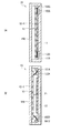
図1は、本発明の第1の実施の形態に係るデジタルカメラ(デジタルカメラ3)の要部構成を断面図で表したものである。このデジタルカメラ3は、いわゆる一眼レフレックス(一眼レフ)デジタルカメラであり、筐体30の内部に、本発明の第1の実施の形態に係る撮像装置(撮像装置1)と、可動ミラー31と、図示しないミラー駆動部(後述するミラー駆動部310)と、ペンタプリズム32と、集光レンズ33と、接眼レンズ34と、ファインダ35と、表示部36と、図示しない表示駆動部(後述する表示駆動部360)とを備えている。なお、ペンタプリズム32、集光レンズ33、接眼レンズ34およびファインダ35は、デジタルカメラ3の観察光学系(以下説明する撮像光学系からの被写体像を観察するための光学系)を構成している。
[First Embodiment]
FIG. 1 is a cross-sectional view showing the main configuration of a digital camera (digital camera 3) according to a first embodiment of the present invention. The digital camera 3 is a so-called single-lens reflex (single-lens reflex) digital camera, and includes an imaging device (imaging device 1) according to the first embodiment of the present invention, a movable mirror 31, and a housing 30. , A mirror drive unit (not shown) (mirror drive unit 310 described later), a pentaprism 32, a condenser lens 33, an eyepiece lens 34, a finder 35, a display unit 36, and a display drive unit (not shown) (display described later). Drive section 360). The pentaprism 32, the condenser lens 33, the eyepiece lens 34, and the finder 35 constitute an observation optical system of the digital camera 3 (an optical system for observing a subject image from an imaging optical system described below). .

撮像装置1は、被写体(撮像対象物)を撮像して撮像データを出力するものである。この撮像装置1は、開口部100を有する開口絞り10と、デジタルカメラ3の撮像光学系としての撮像レンズ11およびマイクロレンズアレイ12と、撮像素子13とを含んで構成されている。なお、撮像装置1の詳細構成については後述する。   The imaging device 1 captures a subject (imaging target) and outputs imaging data. The imaging apparatus 1 includes an aperture stop 10 having an aperture 100, an imaging lens 11 and a microlens array 12 as an imaging optical system of the digital camera 3, and an imaging element 13. The detailed configuration of the imaging device 1 will be described later.

可動ミラー31は、図示しないミラー駆動部(後述するミラー駆動部310)により、上記した観察光学系の光入射側または撮像光学系の光路上に挿脱自在となるように配置されている。具体的には、詳細は後述するが、図1に示したようなペンタプリズム32と撮像装置1との間の光路上(ペンタプリズム32の下部)、またはマイクロレンズアレイ12の光入射側(撮像レンズ11とマイクロレンズアレイ12との間の光路上)に配置されるようになっている。なお、この可動ミラー31は、入射光線を全反射させることが可能な材料(例えば、アルミ増反射コーティングやマルチコーティングなど)により構成される。   The movable mirror 31 is arranged so that it can be inserted into and removed from the light incident side of the observation optical system or the optical path of the imaging optical system by a mirror drive unit (mirror drive unit 310 described later) (not shown). Specifically, although details will be described later, on the optical path between the pentaprism 32 and the imaging apparatus 1 (lower part of the pentaprism 32) as shown in FIG. (On the optical path between the lens 11 and the microlens array 12). The movable mirror 31 is made of a material capable of totally reflecting incident light (for example, an aluminum-enhanced reflection coating or a multi-coating).

ペンタプリズム32は、入射光を90度の角度で反射させて出射することにより、入射光をファインダ35の方向へと導くためのプリズムである。集光レンズ33は、ペンタプリズム32からの入射光を集光するためのレンズであり、接眼レンズ34は、ファインダ35を介して、撮影者の片方の目(後述する片方の目E)において実際に観察するためのレンズである。   The pentaprism 32 is a prism that guides incident light toward the viewfinder 35 by reflecting incident light at an angle of 90 degrees and emitting the reflected light. The condensing lens 33 is a lens for condensing incident light from the pentaprism 32, and the eyepiece 34 is actually connected to the photographer's one eye (one eye E described later) via the finder 35. It is a lens for observation.

表示部36は、撮像装置1により得られる撮像データに基づき、図示しない表示駆動部(後述する表示駆動部360)による表示駆動に従って、被写体像を表示するものである。これにより詳細は後述するが、例えば図2に示したように、この表示部36により被写体像を表示すること(ライブビュー表示)が可能となると共に、この表示部36により表示された被写体像を見て撮像を行うライブビュー撮像モードが可能となっている。また、表示部36では、このようなライブビュー撮像モードや、ファインダ35により被写体像を観察して撮像を行うファインダ観察撮像モードを用いて、図中のシャッタボタン37を押すことにより撮像された撮像画像を表示することもできるようになっている。なお、表示部35は、例えば、液晶パネルや有機ELパネルなどを含んで構成される。   The display unit 36 displays a subject image according to display driving by a display driving unit (not shown) (a display driving unit 360 described later) based on imaging data obtained by the imaging device 1. As will be described in detail later, for example, as shown in FIG. 2, the display unit 36 can display a subject image (live view display), and the subject image displayed by the display unit 36 can be displayed. A live view imaging mode in which imaging is performed by watching is possible. Further, the display unit 36 uses such a live view imaging mode or a finder observation imaging mode in which a subject image is observed by the finder 35 to capture an image captured by pressing the shutter button 37 in the drawing. An image can also be displayed. The display unit 35 includes, for example, a liquid crystal panel or an organic EL panel.

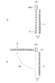
次に、図3〜図7を参照して、撮像装置1の詳細構成について説明する。図3は、撮像装置1の全体構成を、デジタルカメラ3の筐体30内に設けられた前述のミラー駆動部310および表示駆動部360と共に表したものである。   Next, the detailed configuration of the imaging apparatus 1 will be described with reference to FIGS. FIG. 3 illustrates the entire configuration of the imaging apparatus 1 together with the mirror driving unit 310 and the display driving unit 360 provided in the housing 30 of the digital camera 3.

この撮像装置1は、被写体(撮像対象物)2を撮像して撮像データDoutを出力するものであり、被写体2の側から、開口絞り10と、撮像レンズ11と、撮像ユニット15とを備えている。撮像装置1はまた、画像処理部14と、撮像素子駆動部161と、撮像レンズ駆動部162と、制御部17と、位相差検出部191と、距離情報算出部192とを備えている。   This imaging device 1 images a subject (imaging object) 2 and outputs imaging data Dout, and includes an aperture stop 10, an imaging lens 11, and an imaging unit 15 from the subject 2 side. Yes. The imaging apparatus 1 also includes an image processing unit 14, an imaging element driving unit 161, an imaging lens driving unit 162, a control unit 17, a phase difference detection unit 191, and a distance information calculation unit 192.

開口絞り10は、撮像レンズ11の光学的な開口絞りである。この開口絞り10は、例えば図中に示したように、その中央部に一つの円形の開口部100を有している。これにより、詳細は後述するが、開口絞り10を通過した全ての光線が、その進行方向に関する情報を保持するようになっている。   The aperture stop 10 is an optical aperture stop of the imaging lens 11. For example, as shown in the drawing, the aperture stop 10 has one circular opening 100 at the center thereof. As a result, as will be described in detail later, all the light beams that have passed through the aperture stop 10 hold information about their traveling directions.

撮像レンズ11は、被写体を撮像するためのメインレンズであり、例えば、ビデオカメラやスチルカメラ等で使用される一般的な撮像レンズにより構成される。   The imaging lens 11 is a main lens for imaging a subject, and is configured by a general imaging lens used in, for example, a video camera or a still camera.

撮像ユニット部15は、撮像を行う際の撮像機能を担う部分であり、マイクロレンズアレイ12と、撮像素子13と、一対のバイメタル181A,181Bとを含んで構成されている。なお、この撮像ユニット部15の詳細構成については、後述する。   The imaging unit unit 15 is a part that takes an imaging function when performing imaging, and includes a microlens array 12, an imaging element 13, and a pair of bimetals 181A and 181B. The detailed configuration of the imaging unit 15 will be described later.

撮像素子駆動部161は、撮像素子13を駆動してその受光動作の制御を行うものである。   The image sensor driving unit 161 drives the image sensor 13 and controls its light receiving operation.

画像処理部14は、ライブビュー撮像モードの際などに、撮像素子13で得られた撮像データに対して所定の画像処理(並び替え処理を含む画像処理)を施すことにより、撮像データDoutを生成し出力するものである。具体的には、例えば「Light Field Photography」と呼ばれる手法を用いた演算処理を行い、これにより任意の視点からの観察画像や任意の焦点からの観察画像を再構築できるようになっている。なお、この画像処理部14の処理動作の詳細については、後述する。   The image processing unit 14 generates imaging data Dout by performing predetermined image processing (image processing including rearrangement processing) on the imaging data obtained by the imaging element 13 in the live view imaging mode or the like. Output. Specifically, for example, an arithmetic process using a technique called “Light Field Photography” is performed, whereby an observation image from an arbitrary viewpoint and an observation image from an arbitrary focus can be reconstructed. Details of the processing operation of the image processing unit 14 will be described later.

位相差検出部191は、撮像素子13により得られた撮像データに対して、上記画像処理部14と同様にして所定の画像処理(並び替え処理を含む画像処理)を施すことにより、互いに視差の異なる2つの視差画像(2つの視点からの観察画像)を生成する(再構築する)と共に、これら2つの視差画像間の位相差を検出するものである。なお、この位相差検出部191の処理動作の詳細については、後述する。   The phase difference detection unit 191 performs predetermined image processing (image processing including rearrangement processing) on the imaging data obtained by the imaging element 13 in the same manner as the image processing unit 14, so that the parallax of each other is obtained. Two different parallax images (observation images from two viewpoints) are generated (reconstructed), and a phase difference between the two parallax images is detected. Details of the processing operation of the phase difference detector 191 will be described later.

距離情報算出部192は、位相差検出部191により検出された2つの視差画像間の位相差を用いて、撮像レンズ11の合焦動作の際の撮像レンズ11の駆動距離を算出するものである。なお、この距離情報算出部192の処理動作の詳細については、後述する。   The distance information calculation unit 192 calculates the driving distance of the imaging lens 11 during the focusing operation of the imaging lens 11 using the phase difference between the two parallax images detected by the phase difference detection unit 191. . Details of the processing operation of the distance information calculation unit 192 will be described later.

なお、これら位相差検出部191および距離情報算出部192が、本発明における「測距手段」の一具体例に対応する。   The phase difference detection unit 191 and the distance information calculation unit 192 correspond to a specific example of “ranging unit” in the present invention.

撮像レンズ駆動部162は、距離情報算出部192により算出された駆動距離を用いて撮像レンズ11を光軸方向に平行移動させる(駆動する)ことにより、撮像レンズ11の合焦動作を行うものである。撮像レンズ駆動部162は、例えばDCモータなどにより構成される。なお、この撮像レンズ駆動部162が、本発明における「合焦手段」の一具体例に対応する。   The imaging lens driving unit 162 performs a focusing operation of the imaging lens 11 by translating (driving) the imaging lens 11 in the optical axis direction using the driving distance calculated by the distance information calculation unit 192. is there. The imaging lens driving unit 162 is configured by, for example, a DC motor. The imaging lens driving section 162 corresponds to a specific example of “focusing means” in the present invention.

ミラー駆動部310は、撮像装置1における撮像モードに応じた合焦動作および撮像動作に従って、前述の可動ミラー31を駆動するものである。なお、このミラー駆動部310の詳細動作については、後述する。   The mirror driving unit 310 drives the above-described movable mirror 31 according to the focusing operation and the imaging operation corresponding to the imaging mode in the imaging device 1. The detailed operation of the mirror driving unit 310 will be described later.

表示駆動部360は、撮像素子13により得られた撮像データ、または画像処理部14による画像処理後の撮像データ(前述の再構築画像を構成する撮像データ)に基づく撮像画像が表示部36に表示されるように、表示部36の表示駆動を行うものである。   The display driving unit 360 displays a captured image based on imaging data obtained by the imaging element 13 or imaging data after image processing by the image processing unit 14 (imaging data constituting the reconstructed image described above) on the display unit 36. As described above, the display drive of the display unit 36 is performed.

制御部17は、画像処理部14、撮像素子駆動部161、ミラー駆動部310、表示駆動部360および後述する撮像ユニット15内の熱供給部(熱供給部182A,182B)の動作を制御するものである。具体的には、撮像素子駆動部161の駆動動作を適宜制御すると共に、詳細は後述するが、撮像装置1における撮像モードに応じた合焦動作および撮像動作に従って、画像処理部14、撮像ユニット15(具体的には、後述する熱供給部182A,182B)、ミラー駆動部310および表示駆動部360の動作を制御するようになっている。なお、制御部17は、例えばマイクロコンピュータなどにより構成される。   The control unit 17 controls the operations of the image processing unit 14, the image sensor driving unit 161, the mirror driving unit 310, the display driving unit 360, and a heat supply unit (heat supply units 182A and 182B) in the imaging unit 15 described later. It is. Specifically, the driving operation of the image sensor driving unit 161 is appropriately controlled and the details will be described later. According to the focusing operation and the imaging operation corresponding to the imaging mode in the imaging device 1, the image processing unit 14, the imaging unit 15. (Specifically, the heat supply units 182A and 182B described later), the mirror drive unit 310, and the display drive unit 360 are controlled. The control unit 17 is configured by a microcomputer, for example.

ここで、図4〜図7を参照して、撮像ユニット部15の詳細構成について説明する。この撮像ユニット部15には、図4に示したように、筐体150内に、マイクロレンズアレイ12、撮像素子13、バイメタル181A,181Bおよび熱供給部182A,182Bが配置されている。   Here, a detailed configuration of the imaging unit unit 15 will be described with reference to FIGS. As shown in FIG. 4, in the imaging unit unit 15, a microlens array 12, an imaging device 13, bimetals 181 </ b> A and 181 </ b> B, and heat supply units 182 </ b> A and 182 </ b> B are arranged in a housing 150.

マイクロレンズアレイ12は、例えば図5に示したように、複数のマイクロレンズ12−1をマトリクス状に2次元配列したものであり、光軸方向に沿って撮像素子13と互いに近接(好ましくは密着)するように配置されている。また、このマイクロレンズアレイ12は、図3に示したように、後述するライブビュー撮像モード時に、撮像レンズ11の焦点面(図3中の符号f1は、撮像レンズ11の焦点距離を表している)に配置されるようになっている。なお、各マイクロレンズ12−1は、その平面形状が円形となっており、固体レンズや液晶レンズ、液体レンズ、回折レンズなどにより構成される。   For example, as shown in FIG. 5, the microlens array 12 is a two-dimensional array of a plurality of microlenses 12-1, and is close to (preferably in close contact with) the image sensor 13 along the optical axis direction. ) Is arranged to be. Further, as shown in FIG. 3, the microlens array 12 has a focal plane of the imaging lens 11 (a reference sign f1 in FIG. 3 represents a focal length of the imaging lens 11) in a live view imaging mode described later. ). Each microlens 12-1 has a circular planar shape, and is composed of a solid lens, a liquid crystal lens, a liquid lens, a diffraction lens, or the like.

撮像素子13は、マイクロレンズアレイ12からの光を受光して撮像データを取得するものである。この撮像素子13は、図3に示したように、後述するライブビュー撮像モード時に、マイクロレンズアレイ12の焦点面(図中の符号f2は、マイクロレンズアレイ12の焦点距離を表している)に配置されるようになっている。なお、撮像素子13は、マトリクス状に2次元配列された複数のCCD(Charge Coupled Device;電荷結合素子)またはCMOS(Complementary Metal-Oxide Semiconductor)などの2次元撮像素子などにより構成される。   The imaging element 13 receives light from the microlens array 12 and acquires imaging data. As shown in FIG. 3, the imaging element 13 is on the focal plane of the microlens array 12 (reference numeral f <b> 2 in the drawing represents the focal length of the microlens array 12) in the live view imaging mode described later. It is arranged. The imaging device 13 is configured by a two-dimensional imaging device such as a plurality of CCDs (Charge Coupled Devices) or CMOS (Complementary Metal-Oxide Semiconductor) arranged two-dimensionally in a matrix.

このような撮像素子13の受光面(マイクロレンズアレイ12側の面)には、M×N(M,N:整数)個の撮像画素(後述する画素P)がマトリクス状に2次元配置され、複数の画素Pに対してマイクロレンズアレイ12内の1つのマイクロレンズ12−1が割り当てられるようになっている。この受光面上の画素Pの個数は、例えば、M×N=3720×2520=9374400個である。ここで、各マイクロレンズ12−1に割り当てられる画素数(m×n)は、再構築画像の任意の視野での分解能と関連しているため、これらm,nの値が大きくなるに従って、再構築画像の任意の視野での分解能が高くなる。一方、(M/m),(N/n)は、再構築画像の画素数(解像度)と関連しているため、これら(M/m),(N/n)の値が大きくなるに従って、再構築画像の画素数が高くなる。したがって、再構築画像の任意の視野での分解能と画素数とはトレードオフの関係となっている。   On the light receiving surface (surface on the microlens array 12 side) of such an image sensor 13, M × N (M, N: integer) image pixels (pixels P described later) are two-dimensionally arranged in a matrix. One microlens 12-1 in the microlens array 12 is assigned to a plurality of pixels P. The number of pixels P on the light receiving surface is, for example, M × N = 3720 × 2520 = 9374400. Here, since the number of pixels (m × n) assigned to each microlens 12-1 is related to the resolution in an arbitrary field of view of the reconstructed image, as the values of m and n increase, The resolution of the constructed image in an arbitrary field of view increases. On the other hand, since (M / m) and (N / n) are related to the number of pixels (resolution) of the reconstructed image, as the values of (M / m) and (N / n) increase, The number of pixels of the reconstructed image is increased. Accordingly, the resolution and the number of pixels in an arbitrary field of view of the reconstructed image have a trade-off relationship.

なお、撮像素子13の受光面上に、例えば図示しないカラーフィルタを、撮像画素(後述する画素P)単位で2次元配置するようにしてもよい。カラーフィルタとしては、例えば、赤(R)、緑(G)および青(B)の3原色のカラーフィルタ(赤色カラーフィルタ、緑色カラーフィルタおよび青色カラーフィルタ)がR:G:B=1:2:1の比率で市松状に配置されたBayer配列のカラーフィルタ(原色フィルタ)を用いることができる。このようなカラーフィルタを撮像素子13の受光面上に設けるようにすれば、撮像素子13により得られた撮像データを、カラーフィルタの色に対応した複数の色(この場合、3原色)の画素データ(カラーの画素データ)とすることができる。   For example, a color filter (not shown) may be two-dimensionally arranged on the light receiving surface of the image sensor 13 in units of image pickup pixels (pixels P described later). As the color filter, for example, three primary color filters (red color filter, green color filter, and blue color filter) of red (R), green (G), and blue (B) are R: G: B = 1: 2. A Bayer color filter (primary color filter) arranged in a checkered pattern at a ratio of 1 can be used. If such a color filter is provided on the light receiving surface of the image sensor 13, pixels of a plurality of colors (in this case, three primary colors) corresponding to the color of the color filter are obtained from the image data obtained by the image sensor 13. Data (color pixel data) can be used.

バイメタル181A,181Bはそれぞれ、図4に示したように、マイクロレンズアレイ12または撮像素子13の端部に配置されている。これらバイメタル181A,181Bは、例えば図6(A)に示したように、互いに熱膨張率の異なる2つの金属板181A1,181A2が積層されてなり、それらの端部が支持部181A0によって支持されるようになっている。なお、金属板181A1は、例えばインバー(鉄とニッケルとの合金)などにより構成され、金属板181A2は、例えば、鉄とニッケルとの合金にマンガンやクロム、銅などを添加した合金などにより構成される。   Each of the bimetals 181A and 181B is disposed at the end of the microlens array 12 or the image sensor 13 as shown in FIG. For example, as shown in FIG. 6A, these bimetals 181A and 181B are formed by laminating two metal plates 181A1 and 181A2 having different coefficients of thermal expansion, and their end portions are supported by a support portion 181A0. It is like that. The metal plate 181A1 is made of, for example, Invar (an alloy of iron and nickel), and the metal plate 181A2 is made of, for example, an alloy in which manganese, chromium, copper, or the like is added to an alloy of iron and nickel. The

熱供給部182A,182Bはそれぞれ、バイメタル181A,181Bの近傍、具体的には、熱膨張率がより高い金属板側(この場合、金属板181A2等のマイクロレンズアレイ12とは反対側)の近傍に配置されている。このような構成により、例えば図6(B)に示したように、バイメタル181A,181Bに対して熱供給部182A,182Bからそれぞれ所定の熱量Qが供給されると、2つの金属板の熱膨張率の違いに起因してバイメタル181A,181Bの形状が変化し、より熱膨張率の小さい金属板側(例えば、金属板181A1等の側)にバイメタル181A,181Bが反るようになっている。なお、これら熱供給部182A,182Bおよび上記バイメタル181A,181Bが、本発明における「切替手段」および「第1の駆動部」の一具体例に対応する。   The heat supply units 182A and 182B are in the vicinity of the bimetals 181A and 181B, specifically, on the side of the metal plate having a higher coefficient of thermal expansion (in this case, on the side opposite to the microlens array 12 such as the metal plate 181A2). Is arranged. With such a configuration, for example, as shown in FIG. 6B, when a predetermined amount of heat Q is supplied from the heat supply units 182A and 182B to the bimetals 181A and 181B, the thermal expansion of the two metal plates Due to the difference in rate, the shape of the bimetal 181A, 181B changes, and the bimetal 181A, 181B warps to the metal plate side (for example, the side of the metal plate 181A1, etc.) having a smaller thermal expansion coefficient. The heat supply units 182A and 182B and the bimetals 181A and 181B correspond to specific examples of “switching unit” and “first drive unit” in the present invention.

このようにして、撮像ユニット部15では、以下のようなマイクロレンズアレイ12の機能の切替動作がなされるようになっている。すなわち、熱供給部182A,182Bからバイメタル181A,181Bへの熱供給の有無(または熱供給量の大きさ)に応じてバイメタル18A,18Bの形状が変化することにより、マイクロレンズアレイ12が光軸方向に変位するようになっている。   In this way, the imaging unit section 15 performs the function switching operation of the microlens array 12 as described below. That is, the shape of the bimetal 18A, 18B changes according to the presence / absence of heat supply from the heat supply units 182A, 182B to the bimetal 181A, 181B (or the amount of heat supply), so that the microlens array 12 can be It is designed to be displaced in the direction.

具体的には、熱供給部182A,182Bからバイメタル181A,181Bへ熱供給がなされていない場合、図6(A)に示したようにバイメタル181A,181Bの形状は変化しないため、例えば図7(A)に示したように、マイクロレンズアレイ12および撮像素子13は互いに近接(または密着)したままとなる。したがって、撮像レンズ11からの入射光はマイクロレンズアレイ12において屈折されず、そのまま撮像素子13へ到達することになるため、マイクロレンズアレイ12による撮像光学系としての機能が発揮されなくなる。   Specifically, when heat is not supplied from the heat supply units 182A and 182B to the bimetals 181A and 181B, the shape of the bimetals 181A and 181B does not change as shown in FIG. As shown in A), the microlens array 12 and the imaging device 13 remain close to (or in close contact with) each other. Accordingly, the incident light from the imaging lens 11 is not refracted by the microlens array 12 and reaches the imaging element 13 as it is, so that the function as an imaging optical system by the microlens array 12 is not exhibited.

一方、熱供給部182A,182Bからバイメタル181A,181Bへ熱供給がなされている場合、図6(B)に示したようにバイメタル181A,181Bの形状が変化して反り生じるため、例えば図7(B)中の符号P1で示したように、マイクロレンズアレイ12が光軸方向に沿って撮像素子13とは反対側(撮像レンズ11側)に変位し、これによりマイクロレンズアレイ12と撮像素子13との間の相対距離が変化し、マイクロレンズアレイ12が筐体150に近接(または密着)するようになっている。また、このようにマイクロレンズアレイ12が筐体150に近接(または密着)する位置となった場合、前述(図3)のようにマイクロレンズアレイ12と撮像素子13との間の相対距離がマイクロレンズアレイ12の焦点距離f2と一致(または略同一)となるように設定されていることにより、撮像レンズ11からの入射光がマイクロレンズアレイ12において屈折され、撮像素子13上に集光するようになるため、マイクロレンズアレイ12による撮像光学系としての機能が発揮されるようになる。   On the other hand, when heat is supplied from the heat supply units 182A and 182B to the bimetals 181A and 181B, the shape of the bimetals 181A and 181B changes as shown in FIG. As indicated by reference numeral P1 in B), the microlens array 12 is displaced along the optical axis direction to the side opposite to the imaging element 13 (on the imaging lens 11 side), whereby the microlens array 12 and the imaging element 13 are displaced. The microlens array 12 comes close to (or in close contact with) the housing 150. In addition, when the microlens array 12 is in a position close to (or in close contact with) the housing 150 as described above, the relative distance between the microlens array 12 and the imaging element 13 is microscopic as described above (FIG. 3). By being set so as to coincide with (or substantially the same as) the focal length f 2 of the lens array 12, incident light from the imaging lens 11 is refracted by the microlens array 12 and collected on the imaging element 13. Therefore, the function as an imaging optical system by the microlens array 12 is exhibited.

次に、図8〜図19を参照して、本実施の形態のデジタルカメラ3および撮像装置1の作用および効果について詳細に説明する。ここで、図8は、デジタルカメラ3による撮像処理を流れ図で表したものである。   Next, operations and effects of the digital camera 3 and the imaging apparatus 1 according to the present embodiment will be described in detail with reference to FIGS. Here, FIG. 8 is a flowchart showing the imaging process by the digital camera 3.

まず、ユーザによって、ライブビュー撮像モード(表示部36により表示された被写体像を見て撮像を行う撮像モード)を利用するか否かが選択されることにより、制御部17は、ライブビュー撮像モードを実行するか否かを判断する(図8のステップS101)。実行すると判断した場合(ステップS101:Y)、以下のステップS102〜S109,S117によるライブビュー撮像モードがなされる一方、実行しないと判断した場合(ステップS101:N)、以下のステップS110〜S117によるファインダ観察撮像モード(ファインダ35により被写体像を観察して撮像を行う撮像モード)がなされることとなる。   First, the user selects whether or not to use a live view imaging mode (an imaging mode in which imaging is performed by viewing a subject image displayed on the display unit 36), whereby the control unit 17 causes the live view imaging mode. Is determined (step S101 in FIG. 8). If it is determined to execute (step S101: Y), the live view imaging mode in the following steps S102 to S109 and S117 is performed. On the other hand, if it is determined not to execute (step S101: N), the following steps S110 to S117 are performed. A viewfinder observation imaging mode (an imaging mode in which a subject image is observed and imaged by the viewfinder 35) is performed.

(ライブビュー撮像モード)
最初に、図8〜図17を参照して、ライブビュー撮像モードによる撮像処理について説明する。まず、制御部17は、撮像ユニット15内の熱供給部182A,182Bの動作を制御することにより、図7(B)および図9に示したように、マイクロレンズアレイ12を光軸方向に沿って変位させ、マイクロレンズアレイ12と撮像素子13との間の相対距離がマイクロレンズアレイ12の焦点距離f2と一致(または略同一)となるように駆動する(撮像素子と離すようにする)(ステップS102)。これにより、撮像レンズ11からの入射光がマイクロレンズアレイ12において屈折され、撮像素子13上に集光するようになり、マイクロレンズアレイ12による撮像光学系としての機能が発揮されるようになる。次に、制御部17は、ミラー駆動部310の動作を制御することにより、図9に示したように、可動ミラー31が、ペンタプリズム32と撮像装置1との間の観察光学系の光路上(ペンタプリズム32の下部)に配置されるようにする(メインミラーアップ)(ステップS103)。そして図9に示したように、このような撮像レンズ11およびマイクロレンズアレイ12を撮像光学系として撮像素子13により撮像データを取得すると共に、この撮像素子13により得られた撮像データまたは以下説明する画像処理部14による画像処理後の撮像データに基づいて表示駆動部360が表示駆動を行うことにより、例えば図2に示したような、表示部36を用いたライブビュー表示がなされる(ステップS104)。
(Live view imaging mode)
First, imaging processing in the live view imaging mode will be described with reference to FIGS. First, the control unit 17 controls the operation of the heat supply units 182A and 182B in the imaging unit 15 to move the microlens array 12 along the optical axis direction as shown in FIG. 7B and FIG. And is driven so that the relative distance between the microlens array 12 and the image sensor 13 is equal to (or substantially the same as) the focal length f2 of the microlens array 12 (separate from the image sensor) ( Step S102). As a result, incident light from the imaging lens 11 is refracted by the microlens array 12 and is condensed on the imaging element 13, and the function of the microlens array 12 as an imaging optical system is exhibited. Next, the control unit 17 controls the operation of the mirror driving unit 310 so that the movable mirror 31 is placed on the optical path of the observation optical system between the pentaprism 32 and the imaging device 1 as shown in FIG. It is arranged at (lower part of the pentaprism 32) (main mirror up) (step S103). Then, as shown in FIG. 9, imaging data is acquired by the imaging element 13 using the imaging lens 11 and the microlens array 12 as an imaging optical system, and the imaging data obtained by the imaging element 13 or will be described below. The display driving unit 360 performs display driving based on the imaging data after the image processing by the image processing unit 14, thereby performing live view display using the display unit 36 as illustrated in FIG. 2, for example (step S104). ).

ここで、図10および図11を参照して、撮像レンズ11およびマイクロレンズアレイ12を撮像光学系とした撮像動作、ならびに画像処理部14において行われる画像処理(並び替え処理を含む画像処理)の一例(「Light Field Photography」)について説明する。   Here, referring to FIG. 10 and FIG. 11, an imaging operation using the imaging lens 11 and the microlens array 12 as an imaging optical system, and image processing (image processing including rearrangement processing) performed in the image processing unit 14. An example (“Light Field Photography”) will be described.

ステップS104において、撮像装置1では、撮像レンズ11による被写体2の像は、例えば図5に示したような各マイクロレンズ12−1の形状(円形状)に応じて、マイクロレンズアレイ12上に結像する。そして、マイクロレンズアレイ12への入射光線がこのマイクロレンズアレイ12を介して撮像素子13へ到達し、例えば図10に示したように、開口絞り10の円形状が投影された受光領域13−1において受光がなされ、撮像素子13により撮像データが得られる。このとき、マイクロレンズアレイ12への入射光線は、その入射方向に応じて、撮像素子13の異なる位置で受光される。より具体的には、各マイクロレンズ12−1に割り当てられた画素Pの位置により、光線の入射方向が決定される。ここで、この各マイクロレンズ12−1に割り当てられる画素Pが配置された領域(再構築画素領域13D)が、再構築画像の一画素分に相当する。   In step S104, in the imaging apparatus 1, the image of the subject 2 by the imaging lens 11 is formed on the microlens array 12 according to the shape (circular shape) of each microlens 12-1 as shown in FIG. Image. Light incident on the microlens array 12 reaches the image sensor 13 via the microlens array 12, and as shown in FIG. 10, for example, a light receiving region 13-1 onto which the circular shape of the aperture stop 10 is projected. Is received, and imaging data is obtained by the imaging device 13. At this time, the incident light beam to the microlens array 12 is received at different positions of the image sensor 13 according to the incident direction. More specifically, the incident direction of the light beam is determined by the position of the pixel P assigned to each microlens 12-1. Here, the region (reconstructed pixel region 13D) where the pixels P assigned to the respective microlenses 12-1 are arranged corresponds to one pixel of the reconstructed image.

このようにして撮像素子13で得られた撮像データは、画像処理部14へ入力する。そして画像処理部14では、この撮像データに対して所定の画像処理(例えば、任意視点演算処理やリフォーカス演算処理)が施され、これにより画像処理後の撮像データDoutが、撮像装置1の出力データ(再構築画像の画像データ)として出力される。具体的には、例えば図11に示したように、撮像レンズ11の撮像レンズ面上において直交座標系(u,v)を、撮像素子13の撮像面上において直交座標系(x,y)をそれぞれ考え、撮像レンズ11の撮像レンズ面と撮像素子13の撮像面との距離をFとすると、撮像レンズ11および撮像素子13を通る光線L1は、4次元関数L(x,y,u,v)で表されるため、光線の位置情報に加え、光線の進行方向が保持された状態で撮像素子13に記録される。すなわち、各マイクロレンズ12−1に割り当てられた複数の画素Pの配置により、光線の入射方向が決まることとなる。 The imaging data obtained by the imaging element 13 in this way is input to the image processing unit 14. In the image processing unit 14, predetermined image processing (for example, arbitrary viewpoint calculation processing or refocus calculation processing) is performed on the imaging data, and the imaging data Dout after the image processing is output from the imaging device 1. Output as data (image data of a reconstructed image). Specifically, for example, as shown in FIG. 11, an orthogonal coordinate system (u, v) on the imaging lens surface of the imaging lens 11 and an orthogonal coordinate system (x, y) on the imaging surface of the imaging element 13 are used. Considering each, if the distance between the imaging lens surface of the imaging lens 11 and the imaging surface of the imaging device 13 is F, the light beam L1 passing through the imaging lens 11 and the imaging device 13 is a four-dimensional function L F (x, y, u, v), it is recorded on the image sensor 13 in a state where the traveling direction of the light beam is maintained in addition to the position information of the light beam. That is, the incident direction of the light ray is determined by the arrangement of the plurality of pixels P assigned to each microlens 12-1.

次に、このようなライブビュー表示がなされている状況下、制御部17は、ユーザによる測距指示(撮像レンズ11の合焦動作の際に用いられる、撮像レンズ11の駆動距離の算出処理の指示)の有無を判断する(ステップS105)。そのような測距指示がないと判断した場合には(ステップS105:N)、後述するステップS109へと進む一方、測距指示があったと判断した場合には(ステップS105:Y)、次に、位相差検出部191および距離情報算出部192によって、位相差AF(オートフォーカス)を利用した測距動作を行う(ステップS106)と共に、そのような測距動作により算出された撮像レンズ11の駆動距離を用いて、撮像レンズ駆動部162によって、撮像レンズ11の合焦動作(フォーカスレンズ駆動)を行う(ステップS107)。   Next, under such a live view display, the control unit 17 performs a distance measurement instruction (a process for calculating the driving distance of the imaging lens 11 used in the focusing operation of the imaging lens 11) by the user. Whether there is an instruction) is determined (step S105). When it is determined that there is no such distance measurement instruction (step S105: N), the process proceeds to step S109 described later. On the other hand, when it is determined that there is a distance measurement instruction (step S105: Y), next. The phase difference detection unit 191 and the distance information calculation unit 192 perform a distance measurement operation using phase difference AF (autofocus) (step S106) and drive the imaging lens 11 calculated by such a distance measurement operation. Using the distance, the imaging lens driving unit 162 performs a focusing operation (focus lens driving) of the imaging lens 11 (step S107).

ここで、図12〜図16を参照して、位相差AFを利用した測距動作および撮像レンズ11の合焦動作について、詳細に説明する。   Here, with reference to FIG. 12 to FIG. 16, the ranging operation using the phase difference AF and the focusing operation of the imaging lens 11 will be described in detail.

まず、本実施の形態の撮像装置1では、例えば図12に示したように、ステップS104において撮像素子13により得られる撮像データに基づいて、位相差検出部191により、前述の画像処理部14による画像処理(並び替え処理を含む画像処理)と同様にして、撮像データに対して画像処理を施すことにより、互いに異なる2つの視差画像(2つの異なる視点による任意視点画像:図中の矢印P2で示したように、互いに異なる2つの視差による光線LR,LLによる視差画像)が生成されると共に、これら2つの視差画像間の位相差(例えば図中に示した位相差Δφのように、光線LRによる視差画像の位相φRと、光線LLによる視差画像の位相φLとの間の位相差)が検出される。   First, in the imaging apparatus 1 of the present embodiment, as shown in FIG. 12, for example, based on the imaging data obtained by the imaging element 13 in step S104, the phase difference detection unit 191 performs the above-described image processing unit 14. Similar to the image processing (image processing including rearrangement processing), by performing image processing on the captured data, two different parallax images (arbitrary viewpoint images from two different viewpoints: with an arrow P2 in the figure) As shown, the light beams LR and LL with two different parallaxes are generated, and the phase difference between these two parallax images (for example, the light beam LR like the phase difference Δφ shown in the figure). The phase difference between the phase φR of the parallax image due to and the phase φL of the parallax image due to the light ray LL) is detected.

具体的には、位相差検出部191では、まず、例えば図13に示したように、光線LRによる視差画像(任意視点画像)DRと光線LLによる視差画像(任意視点画像)DLとのDisparityが、以下のようにして算出される。すなわち、例えば図13(A)に示したように、視差画像DR内の小領域の部分画像A1(中心座標:(x1,y1))を取り出すと共に、この部分画像A1と同じ小領域の部分画像B1(中心座標:(x1,y1)を視差画像DLの中から取り出し、この部分画像B1の位置を移動させつつ、以下の(1)式による画素相関値が逐次計算される。そしてこの画素相関値が最大となる位置の部分画像B1の中心点が、部分画像A1の中心点に対応する点として検出される。このときのPixelずれが、上記したDisparityに対応する。なお、このような演算処理が、小領域の部分画像A1の取り出し位置を変化させつつ、視差画像DRの全面についてなされることにより、Disparity Map(Disparityの集合)が得られる。   Specifically, in the phase difference detection unit 191, first, for example, as shown in FIG. 13, the disparity between the parallax image (arbitrary viewpoint image) DR by the light beam LR and the parallax image (arbitrary viewpoint image) DL by the light beam LL is calculated. It is calculated as follows. That is, for example, as shown in FIG. 13A, a partial image A1 (center coordinates: (x1, y1)) of a small area in the parallax image DR is extracted, and a partial image of the same small area as this partial image A1 B1 (center coordinates: (x1, y1)) is extracted from the parallax image DL, and the pixel correlation value according to the following equation (1) is sequentially calculated while moving the position of the partial image B1. The center point of the partial image B1 having the maximum value is detected as a point corresponding to the center point of the partial image A1.The pixel shift at this time corresponds to the above-described Disparity. The processing is performed on the entire surface of the parallax image DR while changing the take-out position of the partial image A1 of the small region, whereby the Disparity Map (Disparity set) It is obtained.

Figure 0005056428
Figure 0005056428

次に、距離情報算出部192では、位相差検出部191により検出された2つの視差画像DR,DL間の位相差(Disparity)を用いて、例えば図14および図15に示したように、撮像レンズ11の物体側焦点面をD、撮像レンズ11の焦点距離をF、測定対象までの距離をd、Disparityを求めたときの開口部100の大きさをv、距離Dの物体を撮像したときの撮像レンズ11の像側焦点面をf、距離dの物体を撮像したときの撮像レンズ11の像側焦点面をg、距離dの物体をvの大きさの開口部100を用いて計算された(Disparity×撮像素子13の画素Pの大きさ×マイクロレンズアレイ12の一辺の長さに対する撮像素子13の画素Pの割り当て画素数)の値をhとすると、以下の(2)〜(10)式により、合焦動作の際の撮像レンズ11の駆動距離xが算出される。   Next, the distance information calculation unit 192 uses the phase difference (Disparity) between the two parallax images DR and DL detected by the phase difference detection unit 191 to capture an image as illustrated in FIGS. 14 and 15, for example. When the object-side focal plane of the lens 11 is D, the focal length of the imaging lens 11 is F, the distance to the measurement object is d, the size of the opening 100 when the Disparity is obtained is v, and an object of the distance D is imaged F is the image-side focal plane of the imaging lens 11, g is the image-side focal plane of the imaging lens 11 when an object at a distance d is imaged, and v is the size of the object at the distance d. When the value of (Disparity × size of the pixel P of the image pickup device 13 × number of assigned pixels P of the image pickup device 13 with respect to the length of one side of the microlens array 12) is h, the following (2) to (10 ) The driving distance x of the imaging lens 11 during the focusing operation is calculated from the equation.

すなわち、まず、相似関係により、以下の(2)式が得られると共に、図14および図15により、e=(g−f)であるため、これを(2)式に代入することにより、以下の(3)式が得られ、この(3)式により以下の(4)式が得られる。また、撮像レンズ11の結像式により、以下の(5)式および(6)式が得られるため、(5)式を(4)式に代入することにより、以下の(7)式が得られると共に、(6)式により以下の(8)式が得られる。したがって、(8)式を(7)式に代入することにより、以下の(9)式が得られるため、この(9)式中においてF,D,vの値が既知のものであれば、算出されたDisparityを用いることにより、距離dが得られる。よって、撮像レンズ11の結像式により以下の(10)式が得られるため、駆動距離xだけ撮像レンズ11が移動することにより、dの位置にある物体(被写体)がfの面に結像することになる。
(h/e)=(v/g) …(2)
{h/(g−f)}=(v/g) …(3)
(1/g)=(1/f)×{1−(h/v)} …(4)
(1/F)=(1/g)+(1/d) …(5)
(1/F)=(1/D)+(1/f) …(6)
(1/d)=(1/F)−[(1/f)×{1−(h/v)}] …(7)
f=F×{D/(D−F)} …(8)
(1/d)=(1/F)−[1/{F×D/(D−F)}×{1−(h/v)}]
…(9)
(1/F)={1/(d+x)}+{1/(f−x)} …(10)
That is, first, the following equation (2) is obtained from the similarity relationship, and e = (g−f) according to FIG. 14 and FIG. 15. Therefore, by substituting this into equation (2), (3) is obtained, and the following (4) is obtained by this (3). Moreover, since the following formulas (5) and (6) are obtained by the imaging formula of the imaging lens 11, the following formula (7) is obtained by substituting the formula (5) into the formula (4). In addition, the following equation (8) is obtained from equation (6). Therefore, by substituting the equation (8) into the equation (7), the following equation (9) is obtained. If the values of F, D, and v are known in the equation (9), The distance d is obtained by using the calculated Disparity. Therefore, since the following expression (10) is obtained by the imaging formula of the imaging lens 11, the object (subject) at the position d is imaged on the plane f by moving the imaging lens 11 by the driving distance x. Will do.
(H / e) = (v / g) (2)
{H / (g−f)} = (v / g) (3)
(1 / g) = (1 / f) × {1- (h / v)} (4)
(1 / F) = (1 / g) + (1 / d) (5)
(1 / F) = (1 / D) + (1 / f) (6)
(1 / d) = (1 / F) − [(1 / f) × {1− (h / v)}] (7)
f = F × {D / (D−F)} (8)
(1 / d) = (1 / F) − [1 / {F × D / (D−F)} × {1− (h / v)}]
... (9)
(1 / F) = {1 / (d + x)} + {1 / (fx)} (10)

このようにして、距離情報算出部192では、(10)式により合焦動作の際の撮像レンズ11の駆動距離xが算出される。これにより、例えば図16中の矢印P3で示したように、撮像レンズ11の合焦動作がなされる(ステップS107)。   In this way, the distance information calculation unit 192 calculates the driving distance x of the imaging lens 11 during the focusing operation by the equation (10). Thereby, for example, as indicated by an arrow P3 in FIG. 16, the focusing operation of the imaging lens 11 is performed (step S107).

次に、制御部17は、ユーザによる測距指示の有無を再び判断する(ステップS108)。そのような測距指示がないと判断した場合には(ステップS108:N)、ステップS109へと進む一方、測距指示があったと判断した場合には(ステップS108:Y)、ステップS106,S107における測距動作および合焦動作を再び行う。   Next, the control unit 17 determines again whether or not there is a ranging instruction from the user (step S108). When it is determined that there is no such distance measurement instruction (step S108: N), the process proceeds to step S109, whereas when it is determined that there is a distance measurement instruction (step S108: Y), steps S106 and S107. The distance measuring operation and the focusing operation are performed again.

次に、制御部17は、撮像ユニット15内の熱供給部182A,182Bの動作を制御することにより、図7(A)および図17中の矢印P4で示したように、マイクロレンズアレイ12を光軸方向に沿って変位させ、マイクロレンズアレイ12と撮像素子13とが互いに近接(または密着)するように駆動する(ステップS109)。これにより、撮像レンズ11からの入射光がマイクロレンズアレイ12において屈折されず、そのまま撮像素子13へ到達することにより、マイクロレンズアレイ12による撮像光学系としての機能が発揮されなくなる。   Next, the control unit 17 controls the operation of the heat supply units 182A and 182B in the imaging unit 15 to move the microlens array 12 as shown by the arrow P4 in FIG. 7A and FIG. It is displaced along the optical axis direction, and the microlens array 12 and the image sensor 13 are driven so as to be close to (or in close contact with) each other (step S109). Thereby, the incident light from the imaging lens 11 is not refracted in the microlens array 12 and reaches the imaging element 13 as it is, so that the function as an imaging optical system by the microlens array 12 is not exhibited.

次に、撮像装置1では、撮像レンズ11のみを撮像光学系として撮像動作がなされ(ステップS117)、撮像素子13から得られた撮像データを基に表示駆動部360により表示駆動がなされることにより、表示部36において撮像画素の表示がなされる(ステップS118)。これにより、ライブビュー撮像モードによる撮像処理が完了となる。   Next, in the imaging apparatus 1, an imaging operation is performed using only the imaging lens 11 as an imaging optical system (step S117), and display driving is performed by the display driving unit 360 based on the imaging data obtained from the imaging element 13. The imaging pixels are displayed on the display unit 36 (step S118). Thereby, the imaging process by the live view imaging mode is completed.

(ファインダ観察撮像モード)
次に、図8および図18,図19を参照して、ファインダ観察撮像モードによる撮像処理について説明する。まず、例えば図18に示したように、マイクロレンズアレイ12を光軸方向に沿って変位させ、マイクロレンズアレイ12と撮像素子13とが互いに近接(または密着)するように駆動する(ステップS110)。これにより、マイクロレンズアレイ12による撮像光学系としての機能が発揮されなくなる。次に、制御部17は、ミラー駆動部310の動作を制御することにより、図18に示したように、可動ミラー31が、撮像光学系の光路上(撮像レンズ11とマイクロレンズアレイ12との間の光路上)に配置されるようにする(メインミラーダウン)(ステップS111)。これにより、図18に示したように、観察者(ユーザ)の片方の目Eによるファインダ35を利用した被写体像の観察が可能となる。
(Finder observation imaging mode)
Next, imaging processing in the finder observation imaging mode will be described with reference to FIGS. First, as shown in FIG. 18, for example, the microlens array 12 is displaced along the optical axis direction, and is driven so that the microlens array 12 and the image sensor 13 are close to (or in close contact with) each other (step S110). . Thereby, the function as an imaging optical system by the microlens array 12 is not exhibited. Next, the control unit 17 controls the operation of the mirror driving unit 310, so that the movable mirror 31 is placed on the optical path of the imaging optical system (the imaging lens 11 and the microlens array 12) as shown in FIG. (On the optical path between them) (main mirror down) (step S111). As a result, as shown in FIG. 18, it is possible to observe the subject image using the finder 35 by one eye E of the observer (user).

次に、このようなファインダ35を利用した被写体像の観察がなされている状況下、制御部17は、ユーザによる測距指示の有無を判断する(ステップS112)。そのような測距指示がないと判断した場合には(ステップS112:N)、後述するステップS115へと進む一方、測距指示があったと判断した場合には(ステップS112:Y)、次に、制御部17は、従来より用いられている通常の位相差AF(オートフォーカス)を利用した測距動作を行う(ステップS113)と共に、そのような測距動作により算出された撮像レンズ11の駆動距離を用いて、撮像レンズ駆動部162によって、例えば図19(A)中の矢印P5で示したように、撮像レンズ11の合焦動作(フォーカスレンズ駆動)を行う(ステップS114)。   Next, in a situation where the subject image is observed using such a finder 35, the control unit 17 determines whether or not there is a distance measurement instruction from the user (step S112). If it is determined that there is no such distance measurement instruction (step S112: N), the process proceeds to step S115 described later. If it is determined that there is a distance measurement instruction (step S112: Y), then The control unit 17 performs a distance measuring operation using a normal phase difference AF (autofocus) that has been conventionally used (step S113) and drives the imaging lens 11 calculated by such a distance measuring operation. Using the distance, the imaging lens driving unit 162 performs a focusing operation (focus lens driving) of the imaging lens 11 as indicated by an arrow P5 in FIG. 19A, for example (step S114).

次に、制御部17は、ユーザによる測距指示の有無を再び判断する(ステップS115)。そのような測距指示がないと判断した場合には(ステップS115:N)、ステップS116へと進む一方、測距指示があったと判断した場合には(ステップS115:Y)、ステップS113,S114における測距動作および合焦動作を再び行う。   Next, the control unit 17 determines again whether or not there is a ranging instruction from the user (step S115). If it is determined that there is no such distance measurement instruction (step S115: N), the process proceeds to step S116, while if it is determined that there is a distance measurement instruction (step S115: Y), steps S113 and S114. The distance measuring operation and the focusing operation are performed again.

次に、制御部17は、ミラー駆動部310の動作を制御することにより、例えば図19(B)中の矢印P6で示したように、可動ミラー31が、ペンタプリズム32と撮像装置1との間の観察光学系の光路上(ペンタプリズム32の下部)に配置されるようにする(メインミラーアップ)(ステップS116)。そして撮像装置1では、撮像レンズ11のみを撮像光学系として撮像動作がなされ(ステップS117)、撮像素子13から得られた撮像データを基に表示駆動部360により表示駆動がなされることにより、表示部36において撮像画素の表示がなされる(ステップS118)。これにより、ファインダ観察撮像モードによる撮像処理が完了となる。   Next, the control unit 17 controls the operation of the mirror driving unit 310 so that the movable mirror 31 is moved between the pentaprism 32 and the imaging device 1 as indicated by an arrow P6 in FIG. It is arranged on the optical path of the observation optical system (the lower part of the pentaprism 32) (main mirror up) (step S116). In the imaging apparatus 1, an imaging operation is performed using only the imaging lens 11 as an imaging optical system (step S117), and display driving is performed by the display driving unit 360 based on the imaging data obtained from the imaging element 13, whereby display is performed. The imaging pixels are displayed in the unit 36 (step S118). Thereby, the imaging process by the finder observation imaging mode is completed.

このようにして本実施の形態の撮像装置1およびデジタルカメラ3では、ミラー駆動部310によって、撮像装置1による撮像モード(ライブビュー撮像モードまたはファインダ観察撮像モード)に応じた合焦動作および撮像動作に従って、可動ミラー31が光路上に適切に挿脱されることにより、ファインダ観察撮像モードとライブビュー撮像モードとが、利用可能となる。すなわち、ファインダ観察モードでは、撮像レンズ11の合焦動作の際には可動ミラー31が撮像光学系の光路上に配置されることにより、観察光学系を利用して被写体像の観察および位相差AFによる合焦動作が可能となる一方、撮像動作の際には可動ミラー31が観察光学系の光入射側の光路上に配置されることにより、撮像装置1の撮像光学系を利用して撮像動作がなされる。また、ライブビュー撮像モードでは、撮像レンズ11の合焦動作および撮像動作の際に、可動ミラー31が観察光学系の光入射側の光路上に配置されることにより、撮像装置1および表示部36を利用した被写体像の撮像画像の視認(ライブビュー表示)が可能となると共に、撮像装置1の撮像光学系を利用した合焦動作および撮像動作が可能となる。   As described above, in the imaging apparatus 1 and the digital camera 3 according to the present embodiment, the mirror driving unit 310 causes the focusing operation and the imaging operation according to the imaging mode (live view imaging mode or finder observation imaging mode) by the imaging apparatus 1. Accordingly, the finder observation imaging mode and the live view imaging mode can be used by appropriately inserting and removing the movable mirror 31 on the optical path. That is, in the finder observation mode, the movable mirror 31 is disposed on the optical path of the imaging optical system when the imaging lens 11 is focused, so that the observation optical system is used to observe the subject image and the phase difference AF. On the other hand, during the imaging operation, the movable mirror 31 is arranged on the optical path on the light incident side of the observation optical system, so that the imaging operation using the imaging optical system of the imaging device 1 is performed. Is made. Further, in the live view imaging mode, the movable mirror 31 is arranged on the light incident side of the observation optical system during the focusing operation and the imaging operation of the imaging lens 11, so that the imaging device 1 and the display unit 36 are arranged. Visualization (live view display) of a captured image of a subject image using the image sensor becomes possible, and a focusing operation and an imaging operation using the imaging optical system of the imaging apparatus 1 are possible.

また、バイメタル181A,181Bおよび熱供給部182A,182Bによって、少なくとも撮像レンズ11の合焦動作の際には、撮像装置1内のマイクロレンズアレイ12による撮像光学系としての機能が発揮されるように切替動作がなされることにより、撮像装置1ではライブビュー撮像モードの際に、撮像レンズ11による被写体像がマイクロレンズアレイ12上に結像すると共にこのマイクロレンズアレイ12へ入射した光線が撮像素子13へ到達し、各マイクロレンズ12−1に対応する複数の画素Pで受光されることにより、光の進行方向の情報を含んだ撮像データが得られる。ここで、位相差検出部191および距離情報算出部192では、この撮像データ基づいて画像処理がなされることにより、互いに視差の異なる2つの視差画像DR,DLが生成されると共に、これら2つの視差画像DR,DL間の位相差Δφ(Disparity)が検出されることにより、撮像レンズ11の合焦動作の際の撮像レンズ11の駆動距離xが算出され、この算出された移動距離xを用いて、撮像レンズ駆動部162により撮像レンズ11の合焦動作がなされる。すなわち、ライブビュー撮像モードの際にも、撮像装置1内で生成される2つの視差画像DR,DLを用いることにより、位相差AFを利用した合焦動作が可能となる。   Further, the bimetal 181A, 181B and the heat supply units 182A, 182B can function as an imaging optical system by the microlens array 12 in the imaging device 1 at least during the focusing operation of the imaging lens 11. By performing the switching operation, in the imaging apparatus 1, a subject image by the imaging lens 11 is formed on the microlens array 12 in the live view imaging mode, and a light beam incident on the microlens array 12 is captured by the imaging element 13. The image data including the information on the traveling direction of the light is obtained by receiving the light at a plurality of pixels P corresponding to each microlens 12-1. Here, in the phase difference detection unit 191 and the distance information calculation unit 192, image processing is performed based on the imaging data, thereby generating two parallax images DR and DL having different parallaxes, and the two parallaxes. By detecting the phase difference Δφ (Disparity) between the images DR and DL, the driving distance x of the imaging lens 11 during the focusing operation of the imaging lens 11 is calculated, and this calculated moving distance x is used. The imaging lens drive unit 162 performs the focusing operation of the imaging lens 11. That is, even in the live view imaging mode, by using the two parallax images DR and DL generated in the imaging apparatus 1, a focusing operation using the phase difference AF is possible.

さらに、本実施の形態の撮像装置1およびデジタルカメラ3では、従来のように、観察光学系による観察時に観察光学系側への入射光量が減少したり、ライブビュー表示時と測距時との間でのミラーの切り替えによる振動が発生したりすることもない。   Furthermore, in the imaging apparatus 1 and the digital camera 3 according to the present embodiment, the amount of incident light on the observation optical system side is reduced during observation by the observation optical system, or during live view display and distance measurement, as in the past. There is no vibration caused by switching the mirrors.

以上のように本実施の形態では、表示部36により、ライブビュー撮像モードが利用可能となる。また、ライブビュー撮像モードの際に、撮像装置1内で生成される2つの視差画像間DR,DLの位相差Δφ(Disparity)を検出して撮像レンズ11の駆動距離xを算出すると共に、この算出された駆動距離xを用いて撮像レンズ11の合焦動作を行うようにしたので、ライブビュー撮像モードの際にも位相差AFを利用した合焦動作を行うことができ、ライブビュー撮像モードの際の高速な合焦動作を実現することが可能となる。また、従来のように、観察光学系による観察時に観察光学系側への入射光量が減少したり、ライブビュー表示時と測距時との間でのミラーの切り替えによる振動が発生したりすることもないので、従来よりも利便性を向上させることが可能となる。よって、ライブビュー撮像モードが利用可能となると共に、このライブビュー撮像モードの際の高速な合焦動作を実現しつつ、利便性を向上させることが可能となる。   As described above, in the present embodiment, the live view imaging mode can be used by the display unit 36. Further, in the live view imaging mode, the phase difference Δφ (Disparity) between the two parallax images generated in the imaging device 1 is detected to calculate the driving distance x of the imaging lens 11, and this Since the focusing operation of the imaging lens 11 is performed using the calculated driving distance x, the focusing operation using the phase difference AF can be performed even in the live view imaging mode, and the live view imaging mode is performed. It is possible to realize a high-speed focusing operation at the time of this. In addition, as in the past, the amount of light incident on the observation optical system decreases during observation with the observation optical system, and vibration occurs due to mirror switching between live view display and distance measurement. Therefore, the convenience can be improved as compared with the prior art. Therefore, the live view imaging mode can be used, and convenience can be improved while realizing a high-speed focusing operation in the live view imaging mode.

また、バイメタル181A,181Bおよび熱供給部182A,182Bにより、撮像レンズ11の合焦動作の際には、マイクロレンズアレイ12による撮像光学系としての機能を発揮させる一方、撮像動作の際には、マイクロレンズアレイ12による撮像光学系としての機能を発揮させないようにしたので、撮像動作時の撮像光学系が撮像レンズ11のみとなり、この撮像素子11による被写体像を、撮像素子13上に直接結像させることができる。よって、撮像素子13により得られる撮像データが光の進行方向の情報を含まないものとなるため、そのような情報を含んでいる場合と比べ、撮像動作により得られる撮像画像を、高解像度のものとすることが可能となる。   Further, the bimetal 181A, 181B and the heat supply units 182A, 182B allow the imaging lens 11 to perform a function as an imaging optical system during the focusing operation, while the imaging operation, Since the function of the microlens array 12 as an imaging optical system is not exhibited, the imaging optical system at the time of the imaging operation is only the imaging lens 11, and a subject image by the imaging element 11 is directly formed on the imaging element 13. Can be made. Therefore, since the imaging data obtained by the imaging element 13 does not include information on the traveling direction of light, the captured image obtained by the imaging operation has a high resolution compared to the case where such information is included. It becomes possible.

さらに、撮像装置1による撮像モードに応じた合焦動作および撮像動作に従って可動ミラー31を光路上に適切に挿脱させるようにしたので、ファインダ観察撮像モードとライブビュー撮像モードとの両者を利用することが可能となる。   Furthermore, since the movable mirror 31 is appropriately inserted into and removed from the optical path in accordance with the focusing operation and the imaging operation according to the imaging mode by the imaging device 1, both the finder observation imaging mode and the live view imaging mode are used. It becomes possible.

なお、本実施の形態では、バイメタル181A,181Bおよび熱供給部182A,182Bをマイクロレンズアレイ12の撮像素子13側に配置し、熱供給がないときにマイクロレンズアレイ12が撮像光学系としての機能を発揮しないようにすると共に熱供給があるときにマイクロレンズアレイ12が撮像光学系としての機能を発揮するようにした場合について説明したが、例えば図20(A),図20(B)に示した撮像ユニット部15Aのように、逆に、バイメタル181A,181Bおよび熱供給部182A,182Bをマイクロレンズアレイ12の撮像素子13とは反対側に配置し、熱供給がないとき(図20(A))にマイクロレンズアレイ12が撮像光学系としての機能を発揮するようになると共に、熱供給があるとき(図20(B))に、図中の符号P7で示したように、マイクロレンズアレイ12が撮像光学系としての機能を発揮しないようにしてもよい。このように構成した場合でも、本実施の形態と同様の効果を得ることが可能である。   In the present embodiment, the bimetals 181A and 181B and the heat supply units 182A and 182B are arranged on the imaging element 13 side of the microlens array 12, and the microlens array 12 functions as an imaging optical system when there is no heat supply. The case where the microlens array 12 exhibits the function as the imaging optical system when there is heat supply has been described, but for example, as shown in FIGS. 20 (A) and 20 (B) On the contrary, when the imaging unit unit 15A is disposed, the bimetals 181A and 181B and the heat supply units 182A and 182B are arranged on the side opposite to the imaging element 13 of the microlens array 12 and there is no heat supply (FIG. 20A )) When the microlens array 12 starts to function as an imaging optical system and there is heat supply (see FIG. To 0 (B)), as indicated by reference numeral P7 in FIG microlens array 12 may be configured not to function as an imaging optical system. Even in such a configuration, it is possible to obtain the same effect as in the present embodiment.

また、本実施の形態では、マイクロレンズアレイ12を光軸方向に変位させることにより、マイクロレンズアレイ12と撮像素子13との間の相対距離を変化させる場合について説明したが、例えば、撮像素子13を光軸方向に変位させることにより、マイクロレンズアレイ12と撮像素子13との間の相対距離を変化させるようにしてもよい。このように構成した場合でも、本実施の形態と同様の効果を得ることが可能である。   In the present embodiment, a case has been described in which the relative distance between the microlens array 12 and the image sensor 13 is changed by displacing the microlens array 12 in the optical axis direction. May be changed in the optical axis direction to change the relative distance between the microlens array 12 and the image sensor 13. Even in such a configuration, it is possible to obtain the same effect as in the present embodiment.

また、本実施の形態では、本発明における「切替手段」の一具体例として、マイクロレンズアレイ12または撮像素子13の端部に配置されたバイメタル181A,181Bと、これらバイメタル181A,181Bに対して熱を供給する熱供給部182A,182Bとを挙げて説明したが、これらバイメタル181A,181Bおよび熱供給部182A,182Bの代わりに、マイクロレンズアレイ12または撮像素子13の端部に配置された圧電アクチュエータ(例えば、チタン酸ジルコン酸塩(通称PZT)や、チタン酸バリウム(BaTiO)などにより構成される)と、これら圧電アクチュエータに対して電圧を供給する電圧供給部とを用いるようにしてもよい。 In the present embodiment, as a specific example of the “switching unit” in the present invention, bimetals 181A and 181B disposed at the end of the microlens array 12 or the image sensor 13 and the bimetals 181A and 181B are used. The heat supply units 182A and 182B for supplying heat have been described above. However, instead of the bimetals 181A and 181B and the heat supply units 182A and 182B, the piezoelectric lens disposed at the end of the microlens array 12 or the image sensor 13 is used. An actuator (for example, composed of zirconate titanate (commonly known as PZT) or barium titanate (BaTiO 3 )) and a voltage supply unit that supplies a voltage to these piezoelectric actuators may be used. Good.

[第2の実施の形態]
次に、本発明の第2の実施の形態について説明する。なお、第1の実施の形態における構成要素と同一のものには同一の符号を付し、適宜説明を省略する。
[Second Embodiment]
Next, a second embodiment of the present invention will be described. In addition, the same code | symbol is attached | subjected to the same thing as the component in 1st Embodiment, and description is abbreviate | omitted suitably.

図21は、本実施の形態の撮像装置(撮像装置1A)の全体構成を、本実施の形態のデジタルカメラ(後述するデジタルカメラ3A)の筐体30内に設けられたミラー駆動部310および表示駆動部360と共に表したものである。この撮像装置1Aは、第1の実施の形態の撮像装置1において、撮像装置ユニット15の代わりに、マイクロレンズアレイ12、撮像素子13および回転駆動部183を設けるようにしたものである。   FIG. 21 shows the overall configuration of the imaging apparatus (imaging apparatus 1A) of the present embodiment, the mirror drive unit 310 provided in the housing 30 of the digital camera of the present embodiment (digital camera 3A described later), and the display. This is shown together with the drive unit 360. This imaging device 1A is configured such that, in the imaging device 1 of the first embodiment, a microlens array 12, an imaging element 13, and a rotation drive unit 183 are provided instead of the imaging device unit 15.

マイクロレンズアレイ12は、複数のマイクロレンズ12−1をマトリクス状に2次元配列したものであり、撮像レンズ11の結像面上(図中の符号f1は、撮像レンズ11の焦点距離を表している)に配置されている。   The microlens array 12 is a two-dimensional array of a plurality of microlenses 12-1 arranged in a matrix. The microlens array 12 is formed on the imaging surface of the imaging lens 11 (the symbol f1 in the figure represents the focal length of the imaging lens 11). Arranged).

撮像素子13は、マイクロレンズアレイ12からの光を受光して撮像データD0を取得するものであり、マイクロレンズアレイ12の焦点面(図中の符号f2は、マイクロレンズアレイ12の焦点距離を表している)に配置されている。   The imaging device 13 receives light from the microlens array 12 and acquires imaging data D0. The focal plane of the microlens array 12 (the reference f2 in the figure represents the focal length of the microlens array 12). Are arranged).

回転駆動部183は、例えば回転軸183Aを有するDCモータなどにより構成されており、マイクロレンズアレイ12を撮像光学系の光路上から挿脱自在となるように駆動するものである。具体的には、図中の矢印P8で示したように、マイクロレンズアレイ12を回転駆動することにより、マイクロレンズアレイ12が撮像光学系の光路上から挿脱自在となるようにしている。なお、この回転駆動部183が、本発明における「切替手段」および「第2の駆動部」の一具体例に対応する。   The rotation drive unit 183 is configured by, for example, a DC motor having a rotation shaft 183A, and drives the microlens array 12 so that it can be inserted and removed from the optical path of the imaging optical system. Specifically, as indicated by an arrow P8 in the drawing, the microlens array 12 is rotationally driven so that the microlens array 12 can be inserted and removed from the optical path of the imaging optical system. The rotation drive unit 183 corresponds to a specific example of “switching unit” and “second drive unit” in the present invention.

これにより、回転駆動部183では、撮像レンズ11の合焦動作の際には、例えば図22(A)に示したように、マイクロレンズアレイ12と撮像素子13との間の相対距離がマイクロレンズアレイ12の焦点距離f2と略同一となるようにマイクロレンズアレイ12を撮像光学系の光路上に挿入配置することにより、マイクロレンズアレイ12による撮像光学系としての機能を発揮させるようになっている。一方、撮像動作の際には、例えば図22(B)中の矢印P9で示したように、マイクロレンズアレイ12が撮像光学系の光路上から外れるようにマイクロレンズアレイ12を配置することにより、マイクロレンズアレイ12による撮像光学系としての機能を発揮させないようになっている。   Thereby, in the rotation drive unit 183, when the imaging lens 11 is focused, for example, as shown in FIG. 22A, the relative distance between the microlens array 12 and the imaging element 13 is less than the microlens. By inserting and arranging the microlens array 12 on the optical path of the imaging optical system so as to be substantially the same as the focal length f2 of the array 12, the function of the microlens array 12 as an imaging optical system is exhibited. . On the other hand, when the imaging operation is performed, for example, as indicated by an arrow P9 in FIG. 22B, the microlens array 12 is arranged so that the microlens array 12 is out of the optical path of the imaging optical system. The function as an imaging optical system by the microlens array 12 is not exhibited.

次に、図23〜図25を参照して、本実施の形態のデジタルカメラ3Aおよび撮像装置1Aの作用および効果について詳細に説明する。ここで、図23は、デジタルカメラ3Aによる撮像処理を流れ図で表したものである。   Next, operations and effects of the digital camera 3A and the imaging apparatus 1A according to the present embodiment will be described in detail with reference to FIGS. Here, FIG. 23 is a flowchart showing the imaging process by the digital camera 3A.

まず、第1の実施の形態と同様に、ユーザによって、ライブビュー撮像モードを利用するか否かが選択されることにより、制御部17は、ライブビュー撮像モードを実行するか否かを判断する(図23のステップS201)。実行すると判断した場合(ステップS201:Y)、以下のステップS202〜S209,S217によるライブビュー撮像モードがなされる一方、実行しないと判断した場合(ステップS201:N)、以下のステップS210〜S217によるファインダ観察撮像モードがなされることとなる。   First, as in the first embodiment, the control unit 17 determines whether or not to execute the live view imaging mode by selecting whether or not to use the live view imaging mode by the user. (Step S201 in FIG. 23). When it is determined to execute (step S201: Y), the live view imaging mode according to the following steps S202 to S209 and S217 is performed, whereas when it is determined not to execute (step S201: N), according to the following steps S210 to S217. The viewfinder observation imaging mode is performed.

(ライブビュー撮像モード)
最初に、図23および図24を参照して、ライブビュー撮像モードによる撮像処理について説明する。まず、制御部17は、回転駆動部183の動作を制御することにより、図22(A)および図24(A)に示したように、マイクロレンズアレイ12と撮像素子13との間の相対距離がマイクロレンズアレイ12の焦点距離f2と略同一となるように、マイクロレンズアレイ12を撮像光学系の光路上に挿入配置させる(ステップS202)。これにより、マイクロレンズアレイ12による撮像光学系としての機能が発揮されるようになる。次に、制御部17は、ミラー駆動部310の動作を制御することにより、図24(A)に示したように、可動ミラー31が、ペンタプリズム32と撮像装置1との間の観察光学系の光路上(ペンタプリズム32の下部)に配置されるようにする(メインミラーアップ)(ステップS203)。これにより、図24(A)および図2に示したように、表示部36を用いたライブビュー表示がなされる(ステップS204)。
(Live view imaging mode)
First, imaging processing in the live view imaging mode will be described with reference to FIGS. First, the control unit 17 controls the operation of the rotation drive unit 183, thereby making the relative distance between the microlens array 12 and the image sensor 13 as shown in FIGS. 22 (A) and 24 (A). Is placed on the optical path of the imaging optical system so that is substantially the same as the focal length f2 of the microlens array 12 (step S202). Thereby, the function as an imaging optical system by the microlens array 12 is exhibited. Next, the control unit 17 controls the operation of the mirror driving unit 310 so that the movable mirror 31 is an observation optical system between the pentaprism 32 and the imaging device 1 as shown in FIG. (Up to the main mirror) (step S203). Thereby, as shown in FIG. 24A and FIG. 2, live view display using the display unit 36 is performed (step S204).

次に、ステップS205〜S208では、第1の実施の形態のステップS105〜108と同様にして、ライブビュー表示がなされている状況下、位相差検出部191および距離情報算出部192による位相差AFを利用した測距動作がなされ(ステップS206)、これにより例えば図24(B)中の矢印P10で示したように、撮像レンズ11の合焦動作(フォーカスレンズ駆動)がなされる(ステップS207)。   Next, in steps S205 to S208, as in steps S105 to 108 of the first embodiment, the phase difference AF by the phase difference detection unit 191 and the distance information calculation unit 192 is performed in a state where live view display is performed. Is performed (step S206), and as a result, for example, as indicated by an arrow P10 in FIG. 24B, the focusing operation (focus lens driving) of the imaging lens 11 is performed (step S207). .

次に、制御部17は、回転駆動部183の動作を制御することにより、図22(B)および図24(C)中の矢印P11で示したように、マイクロレンズアレイ12が撮像光学系の光路上から外れるようにマイクロレンズアレイ12を配置させる(ステップS209)。これにより、マイクロレンズアレイ12による撮像光学系としての機能が発揮されなくなる。そして撮像装置1では、撮像レンズ11のみを撮像光学系として撮像動作がなされ(ステップS217)、表示部36において撮像画素の表示がなされる(ステップS218)。これにより、ライブビュー撮像モードによる撮像処理が完了となる。   Next, the control unit 17 controls the operation of the rotation driving unit 183, so that the microlens array 12 is connected to the imaging optical system as indicated by an arrow P11 in FIGS. 22B and 24C. The microlens array 12 is arranged so as to be out of the optical path (step S209). Thereby, the function as an imaging optical system by the microlens array 12 is not exhibited. In the imaging apparatus 1, an imaging operation is performed using only the imaging lens 11 as an imaging optical system (step S217), and imaging pixels are displayed on the display unit 36 (step S218). Thereby, the imaging process by the live view imaging mode is completed.

(ファインダ観察撮像モード)
次に、図23および図25を参照して、ファインダ観察撮像モードによる撮像処理について説明する。まず、制御部17は、回転駆動部183の動作を制御することにより、例えば図25(A)中の矢印P13で示したように、マイクロレンズアレイ12が撮像光学系の光路上から外れるようにマイクロレンズアレイ12を配置させる(ステップS210)。これにより、マイクロレンズアレイ12による撮像光学系としての機能が発揮されなくなる。次に、制御部17は、ミラー駆動部310の動作を制御することにより、図25(A)に示したように、可動ミラー31が、撮像光学系の光路上(撮像レンズ11とマイクロレンズアレイ12との間の光路上)に配置されるようにする(メインミラーダウン)(ステップS211)。これにより、図25(A)に示したように、観察者(ユーザ)の片方の目Eによるファインダ35を利用した被写体像の観察が可能となる。
(Finder observation imaging mode)
Next, imaging processing in the finder observation imaging mode will be described with reference to FIGS. First, the control unit 17 controls the operation of the rotation driving unit 183 so that the microlens array 12 is removed from the optical path of the imaging optical system, for example, as indicated by an arrow P13 in FIG. The microlens array 12 is disposed (step S210). Thereby, the function as an imaging optical system by the microlens array 12 is not exhibited. Next, the control unit 17 controls the operation of the mirror driving unit 310 so that the movable mirror 31 is on the optical path of the imaging optical system (the imaging lens 11 and the microlens array) as shown in FIG. 12 (on the optical path between the two) (main mirror down) (step S211). As a result, as shown in FIG. 25A, it is possible to observe the subject image using the finder 35 with one eye E of the observer (user).

次に、ステップS212〜S215では、第1の実施の形態のステップS112〜115と同様にして、ファインダ35を利用した被写体像の観察がなされている状況下、制御部17による通常の位相差AF(オートフォーカス)を利用した測距動作がなされ(ステップS213)、これにより例えば図25(B)中の矢印P12で示したように、撮像レンズ11の合焦動作(フォーカスレンズ駆動)がなされる(ステップS214)。   Next, in steps S212 to S215, in the same manner as steps S112 to 115 of the first embodiment, the normal phase difference AF by the control unit 17 is performed under the situation where the subject image is observed using the finder 35. A distance measuring operation using (autofocus) is performed (step S213), and as a result, for example, as indicated by an arrow P12 in FIG. 25B, a focusing operation (focus lens driving) of the imaging lens 11 is performed. (Step S214).

次に、制御部17は、ミラー駆動部310の動作を制御することにより、例えば図25(C)中の矢印P14で示したように、可動ミラー31が、ペンタプリズム32と撮像装置1との間の観察光学系の光路上(ペンタプリズム32の下部)に配置されるようにする(メインミラーアップ)(ステップS216)。そして撮像装置1では、撮像レンズ11のみを撮像光学系として撮像動作がなされ(ステップS217)、表示部36において撮像画素の表示がなされる(ステップS218)。これにより、ファインダ観察撮像モードによる撮像処理が完了となる。   Next, the control unit 17 controls the operation of the mirror driving unit 310 so that the movable mirror 31 moves between the pentaprism 32 and the imaging device 1 as indicated by an arrow P14 in FIG. It is arranged on the optical path of the observation optical system between them (lower part of the pentaprism 32) (main mirror up) (step S216). In the imaging apparatus 1, an imaging operation is performed using only the imaging lens 11 as an imaging optical system (step S217), and imaging pixels are displayed on the display unit 36 (step S218). Thereby, the imaging process by the finder observation imaging mode is completed.

以上のように本実施の形態においても、第1の実施の形態と同様の作用により、同様の効果を得ることができる。すなわち、ライブビュー撮像モードが利用可能となると共に、このライブビュー撮像モードの際の高速な合焦動作を実現しつつ、利便性を向上させることが可能となる。   As described above, also in the present embodiment, the same effect can be obtained by the same operation as in the first embodiment. That is, the live view imaging mode can be used, and convenience can be improved while realizing a high-speed focusing operation in the live view imaging mode.

具体的には、回転駆動部183によってマイクロレンズアレイ12を回転駆動することにより、マイクロレンズアレイ12が撮像光学系の光路上から挿脱自在となるようにしたので、上記の効果を得ることが可能となる。   Specifically, the microlens array 12 is rotationally driven by the rotation driving unit 183 so that the microlens array 12 can be inserted and removed from the optical path of the imaging optical system, and thus the above-described effect can be obtained. It becomes possible.

また、本実施の形態においても、撮像装置1による撮像モードに応じた合焦動作および撮像動作に従って可動ミラー31を光路上に適切に挿脱させるようにしたので、第1の実施の形態と同様に、ファインダ観察撮像モードとライブビュー撮像モードとの両者を利用することが可能となる。   Also in the present embodiment, since the movable mirror 31 is appropriately inserted into and removed from the optical path in accordance with the focusing operation and the imaging operation according to the imaging mode by the imaging apparatus 1, the same as in the first embodiment. In addition, both the finder observation imaging mode and the live view imaging mode can be used.

なお、本実施の形態では、図21中の矢印P8で示したように、回転駆動部183によってマイクロレンズアレイ12を、光軸を含む平面内で回転駆動させる(紙面内で回転駆動させる)場合について説明したが、例えば、回転駆動部183によってマイクロレンズアレイ12を、光軸に垂直な平面内で回転駆動させる(紙面に垂直な平面内で回転駆動させる)ようにしてもよい。このように構成した場合でも、本実施の形態と同様の効果を得ることが可能である。   In the present embodiment, as indicated by an arrow P8 in FIG. 21, the rotation driving unit 183 rotates the microlens array 12 in a plane including the optical axis (rotates in the paper). However, for example, the rotation driving unit 183 may rotate the microlens array 12 in a plane perpendicular to the optical axis (rotation drive in a plane perpendicular to the paper surface). Even in such a configuration, it is possible to obtain the same effect as in the present embodiment.

[第3の実施の形態]
次に、本発明の第3の実施の形態について説明する。なお、第1の実施の形態または第2の実施の形態における構成要素と同一のものには同一の符号を付し、適宜説明を省略する。
[Third Embodiment]
Next, a third embodiment of the present invention will be described. In addition, the same code | symbol is attached | subjected to the same thing as the component in 1st Embodiment or 2nd Embodiment, and description is abbreviate | omitted suitably.

図26は、本実施の形態の撮像装置(撮像装置1B)の全体構成を、本実施の形態のデジタルカメラ(後述するデジタルカメラ3B)の筐体30内に設けられたミラー駆動部310および表示駆動部360と共に表したものである。この撮像装置1Bは、第1の実施の形態の撮像装置1において、撮像装置ユニット15の代わりに、マイクロレンズアレイ12B、撮像素子13および電圧供給部163を設けるようにしたものである。   FIG. 26 shows the overall configuration of the imaging apparatus (imaging apparatus 1B) of the present embodiment, the mirror drive unit 310 provided in the housing 30 of the digital camera of the present embodiment (digital camera 3B described later), and the display. This is shown together with the drive unit 360. This imaging apparatus 1B is configured such that, in the imaging apparatus 1 of the first embodiment, a microlens array 12B, an imaging element 13, and a voltage supply unit 163 are provided instead of the imaging apparatus unit 15.

マイクロレンズアレイ12Bは、複数のマイクロレンズ12B−1をマトリクス状に2次元配列したものであり、撮像レンズ11の結像面上(図中の符号f1は、撮像レンズ11の焦点距離を表している)に配置されている。なお、このマイクロレンズアレイ12Bの詳細構成は、後述する。   The microlens array 12B is a two-dimensional arrangement of a plurality of microlenses 12B-1 in a matrix. Arranged). The detailed configuration of the microlens array 12B will be described later.

撮像素子13は、マイクロレンズアレイ12からの光を受光して撮像データD0を取得するものであり、マイクロレンズアレイ12の焦点面(図中の符号f2は、マイクロレンズアレイ12の焦点距離を表している)に配置されている。   The imaging device 13 receives light from the microlens array 12 and acquires imaging data D0. The focal plane of the microlens array 12 (the reference f2 in the figure represents the focal length of the microlens array 12). Are arranged).

電圧供給部163は、マイクロレンズアレイ12B内のマイクロレンズ12B−1に対して電圧を供給するものであり、この電圧の供給の有無に応じて、マイクロレンズアレイ12Bによる撮像光学系としての機能の切替動作を行うようになっている。なお、この電圧供給部163は、本発明における「切替手段」の一具体例に対応する。   The voltage supply unit 163 supplies a voltage to the microlens 12B-1 in the microlens array 12B, and functions as an imaging optical system by the microlens array 12B according to whether or not the voltage is supplied. Switching operation is performed. The voltage supply unit 163 corresponds to a specific example of “switching means” in the present invention.

次に、図27および図28を参照して、マイクロレンズアレイ12Bの詳細構成および作用について説明する。ここで図27は、マイクロレンズアレイ12の断面構成を表したものである。   Next, with reference to FIGS. 27 and 28, the detailed configuration and operation of the microlens array 12B will be described. Here, FIG. 27 shows a cross-sectional configuration of the microlens array 12.

このマイクロレンズアレイ12Bでは、対向する一対の基板121,125間に液晶層123が形成され、この液晶層123と基板121,125との間には、それぞれ、電極122,124が形成されている。   In the microlens array 12B, a liquid crystal layer 123 is formed between a pair of opposing substrates 121 and 125, and electrodes 122 and 124 are formed between the liquid crystal layer 123 and the substrates 121 and 125, respectively. .

基板121,125は、それぞれ、例えばガラス基板などの透明基板により構成され、入射光線を透過可能となっている。電極122,124には、電圧供給部撮像モード切替部15から電圧が供給される。これら電極122,124は、それぞれ、例えばITO(Indium Tin Oxide;酸化インジウムスズ)などの透明電極により構成され、基板121,125と同様に、入射光線を透過可能となっている。電極122,124の表面S11,S12のうち、電極122側の表面S11には、凹状の複数の曲面がマトリクス状に形成され、これにより複数の液晶マイクロレンズの電極122を構成するようになっている。液晶層123は、例えばネマティック液晶などの液晶材料により構成され、電極122,124間に印加される電圧に応じて屈折率が変化するようになっている。   Each of the substrates 121 and 125 is made of a transparent substrate such as a glass substrate, and can transmit incident light. A voltage is supplied from the voltage supply unit imaging mode switching unit 15 to the electrodes 122 and 124. Each of the electrodes 122 and 124 is configured by a transparent electrode such as ITO (Indium Tin Oxide), and can transmit incident light as in the case of the substrates 121 and 125. Of the surfaces S11 and S12 of the electrodes 122 and 124, a plurality of concave curved surfaces are formed in a matrix on the surface S11 on the electrode 122 side, thereby constituting the electrodes 122 of a plurality of liquid crystal microlenses. Yes. The liquid crystal layer 123 is made of, for example, a liquid crystal material such as nematic liquid crystal, and the refractive index changes according to the voltage applied between the electrodes 122 and 124.

なお、様々な波長領域の光を含んだ自然光を撮像に利用する場合には、電極122側の表面S11を非球面とし、マイクロレンズ12B−1を非球面レンズとするのが好ましい。球面レンズで構成した場合と比べて曲率を小さくなり、光学設計が容易になるからである。また、回折レンズで構成した場合と比較すると、入射光を屈折させる際の波長依存性がなくなるため、軸上色収差などのおそれを回避し、様々な波長領域の光を含んだ自然光による撮像に適した構成とすることができるからである。なお、単色光を用いたイメージング用途などの場合には、上記のような波長依存性や軸上色収差の問題がないため、逆に回折レンズで構成したほうが、非球面レンズで構成した場合と比べて優れた光学特性を得ることができると考えられる。   When natural light including light in various wavelength regions is used for imaging, the surface S11 on the electrode 122 side is preferably an aspherical surface and the microlens 12B-1 is preferably an aspherical lens. This is because the curvature is reduced compared to the case of using a spherical lens, and the optical design is facilitated. Compared with a diffractive lens, the wavelength dependence when refracting incident light is eliminated, so that there is no risk of axial chromatic aberration, making it suitable for imaging with natural light including light in various wavelength regions. It is because it can be set as the structure. In the case of imaging applications using monochromatic light, there is no problem with wavelength dependency or axial chromatic aberration as described above, so conversely, a diffractive lens is used compared to an aspheric lens. It is considered that excellent optical characteristics can be obtained.

このような構成によりマイクロレンズアレイ12Bでは、電圧供給部163から電極122,124間への電圧供給の有無に応じて液晶層123の屈折率が変化し、マイクロレンズアレイ12Bへの入射光線の進行方向が変化するようになっている。   With such a configuration, in the microlens array 12B, the refractive index of the liquid crystal layer 123 changes according to the presence or absence of voltage supply from the voltage supply unit 163 to the electrodes 122 and 124, and the incident light beam advances to the microlens array 12B. The direction is changing.

具体的には、電圧供給部163から電極122,124間へ電圧供給がなされていない場合、液晶層123の屈折率は変化しないため、例えば図28(A)に示したように、マイクロレンズアレイ12Bへの入射光線はマイクロレンズアレイ12Bにおいて屈折されず、光軸L0に沿ってそのまま進行する。これにより、マイクロレンズアレイ12による撮像光学系としての機能が発揮しないようになる。   Specifically, when no voltage is supplied from the voltage supply unit 163 to the electrodes 122 and 124, the refractive index of the liquid crystal layer 123 does not change. For example, as shown in FIG. The incident light beam to 12B is not refracted in the microlens array 12B, and proceeds as it is along the optical axis L0. Thereby, the function as an imaging optical system by the microlens array 12 is not exhibited.

一方、電圧供給部163から電極122,124間へ電圧供給がなされている場合、液晶層123の屈折率が変化するため、例えば図28(B)に示したように、マイクロレンズアレイ12Bへの入射光線がマイクロレンズアレイ12Bにおいて屈折され、例えば光軸L0上の焦点P15に集光する。これにより、マイクロレンズアレイ12による撮像光学系としての機能が発揮するようになる。   On the other hand, when the voltage is supplied from the voltage supply unit 163 to the electrodes 122 and 124, the refractive index of the liquid crystal layer 123 changes. For example, as shown in FIG. The incident light beam is refracted in the microlens array 12B and is collected at, for example, a focal point P15 on the optical axis L0. Thereby, the function as an imaging optical system by the microlens array 12 comes to exhibit.

次に、図29〜図31を参照して、本実施の形態のデジタルカメラ3Bおよび撮像装置1Bの作用および効果について詳細に説明する。ここで、図29は、デジタルカメラ3Bによる撮像処理を流れ図で表したものである。   Next, operations and effects of the digital camera 3B and the imaging device 1B according to the present embodiment will be described in detail with reference to FIGS. Here, FIG. 29 shows an imaging process by the digital camera 3B in a flowchart.

まず、第1の実施の形態と同様に、ユーザによって、ライブビュー撮像モードを利用するか否かが選択されることにより、制御部17は、ライブビュー撮像モードを実行するか否かを判断する(図29のステップS301)。実行すると判断した場合(ステップS301:Y)、以下のステップS302〜S309,S317によるライブビュー撮像モードがなされる一方、実行しないと判断した場合(ステップS301:N)、以下のステップS310〜S317によるファインダ観察撮像モードがなされることとなる。   First, as in the first embodiment, the control unit 17 determines whether or not to execute the live view imaging mode by selecting whether or not to use the live view imaging mode by the user. (Step S301 in FIG. 29). When it is determined to execute (step S301: Y), the live view imaging mode according to the following steps S302 to S309 and S317 is performed, but when it is determined not to execute (step S301: N), the following steps S310 to S317 are performed. The viewfinder observation imaging mode is performed.

(ライブビュー撮像モード)
最初に、図29および図30を参照して、ライブビュー撮像モードによる撮像処理について説明する。まず、制御部17は、電圧供給部163の動作を制御することにより、図28(B)および図30(A)に示したように、マイクロレンズアレイ12Bによる撮像光学系としての機能が発揮される(凸レンズとして機能する)ようにする(ステップS302)。次に、制御部17は、ミラー駆動部310の動作を制御することにより、図30(A)に示したように、可動ミラー31が、ペンタプリズム32と撮像装置1との間の観察光学系の光路上(ペンタプリズム32の下部)に配置されるようにする(メインミラーアップ)(ステップS303)。これにより、図30(A)および図2に示したように、表示部36を用いたライブビュー表示がなされる(ステップS204)。
(Live view imaging mode)
First, imaging processing in the live view imaging mode will be described with reference to FIGS. 29 and 30. First, the control unit 17 controls the operation of the voltage supply unit 163, thereby functioning as an imaging optical system using the microlens array 12B as shown in FIGS. 28B and 30A. (Function as a convex lens) (step S302). Next, the control unit 17 controls the operation of the mirror driving unit 310 so that the movable mirror 31 is an observation optical system between the pentaprism 32 and the imaging device 1 as shown in FIG. (Up to the main mirror) (step S303). Thereby, as shown in FIG. 30A and FIG. 2, live view display using the display unit 36 is performed (step S204).

次に、ステップS305〜S308では、第1の実施の形態のステップS105〜108と同様にして、ライブビュー表示がなされている状況下、位相差検出部191および距離情報算出部192による位相差AFを利用した測距動作がなされ(ステップS306)、これにより例えば図30(B)中の矢印P16で示したように、撮像レンズ11の合焦動作(フォーカスレンズ駆動)がなされる(ステップS307)。   Next, in steps S305 to S308, in the same manner as steps S105 to 108 of the first embodiment, the phase difference AF by the phase difference detection unit 191 and the distance information calculation unit 192 is performed in a state where live view display is performed. Is performed (step S306), and as a result, for example, as indicated by an arrow P16 in FIG. 30B, the focusing operation (focus lens drive) of the imaging lens 11 is performed (step S307). .

次に、制御部17は、電圧供給部163の動作を制御することにより、図28(A)および図30(C)に示したように、マイクロレンズアレイ12Bによる撮像光学系としての機能が発揮されない(平板として機能する)ようにする(ステップS309)。そして撮像装置1では、撮像レンズ11のみを撮像光学系として撮像動作がなされ(ステップS317)、表示部36において撮像画素の表示がなされる(ステップS318)。これにより、ライブビュー撮像モードによる撮像処理が完了となる。   Next, the control unit 17 controls the operation of the voltage supply unit 163 so that the microlens array 12B functions as an imaging optical system, as shown in FIGS. 28A and 30C. Is not performed (functions as a flat plate) (step S309). In the imaging apparatus 1, an imaging operation is performed using only the imaging lens 11 as an imaging optical system (step S317), and imaging pixels are displayed on the display unit 36 (step S318). Thereby, the imaging process by the live view imaging mode is completed.

(ファインダ観察撮像モード)
次に、図29および図31を参照して、ファインダ観察撮像モードによる撮像処理について説明する。まず、制御部17は、電圧供給部163の動作を制御することにより、例えば図31(A)に示したように、マイクロレンズアレイ12Bによる撮像光学系としての機能が発揮されない(平板として機能する)ようにする(ステップS310)。次に、制御部17は、ミラー駆動部310の動作を制御することにより、図31(A)に示したように、可動ミラー31が、撮像光学系の光路上(撮像レンズ11とマイクロレンズアレイ12Bとの間の光路上)に配置されるようにする(メインミラーダウン)(ステップS311)。これにより、図31(A)に示したように、観察者(ユーザ)の片方の目Eによるファインダ35を利用した被写体像の観察が可能となる。
(Finder observation imaging mode)
Next, imaging processing in the finder observation imaging mode will be described with reference to FIGS. 29 and 31. FIG. First, the control unit 17 controls the operation of the voltage supply unit 163, so that the function as an imaging optical system by the microlens array 12B is not exhibited (for example, functions as a flat plate) as shown in FIG. (Step S310). Next, the control unit 17 controls the operation of the mirror driving unit 310 so that the movable mirror 31 is on the optical path of the imaging optical system (the imaging lens 11 and the microlens array) as shown in FIG. 12B (on the optical path between the main mirror 12B) (main mirror down) (step S311). As a result, as shown in FIG. 31A, it is possible to observe the subject image using the finder 35 with one eye E of the observer (user).

次に、ステップS312〜S315では、第1の実施の形態のステップS112〜115と同様にして、ファインダ35を利用した被写体像の観察がなされている状況下、制御部17による通常の位相差AF(オートフォーカス)を利用した測距動作がなされ(ステップS313)、これにより例えば図31(B)中の矢印P17で示したように、撮像レンズ11の合焦動作(フォーカスレンズ駆動)がなされる(ステップS314)。   Next, in steps S312 to S315, as in steps S112 to S115 in the first embodiment, the normal phase difference AF by the control unit 17 is performed under the situation where the subject image is observed using the finder 35. A distance measuring operation using (autofocus) is performed (step S313), and as a result, for example, as indicated by an arrow P17 in FIG. 31B, a focusing operation (focus lens driving) of the imaging lens 11 is performed. (Step S314).

次に、制御部17は、ミラー駆動部310の動作を制御することにより、例えば図30(C)中の矢印P18で示したように、可動ミラー31が、ペンタプリズム32と撮像装置1との間の観察光学系の光路上(ペンタプリズム32の下部)に配置されるようにする(メインミラーアップ)(ステップS316)。そして撮像装置1では、撮像レンズ11のみを撮像光学系として撮像動作がなされ(ステップS317)、表示部36において撮像画素の表示がなされる(ステップS318)。これにより、ファインダ観察撮像モードによる撮像処理が完了となる。   Next, the control unit 17 controls the operation of the mirror driving unit 310 so that the movable mirror 31 moves between the pentaprism 32 and the imaging device 1 as indicated by an arrow P18 in FIG. It is arranged on the optical path of the observation optical system (the lower part of the pentaprism 32) (main mirror up) (step S316). In the imaging apparatus 1, an imaging operation is performed using only the imaging lens 11 as an imaging optical system (step S317), and imaging pixels are displayed on the display unit 36 (step S318). Thereby, the imaging process by the finder observation imaging mode is completed.

以上のように本実施の形態においても、第1の実施の形態と同様の作用により、同様の効果を得ることができる。すなわち、ライブビュー撮像モードが利用可能となると共に、このライブビュー撮像モードの際の高速な合焦動作を実現しつつ、利便性を向上させることが可能となる。   As described above, also in the present embodiment, the same effect can be obtained by the same operation as in the first embodiment. That is, the live view imaging mode can be used, and convenience can be improved while realizing a high-speed focusing operation in the live view imaging mode.

具体的には、マイクロレンズアレイ12Bが、印加電圧に応じて入射光線の屈折方向を変位可能な複数のマイクロレンズ12B−1により構成されると共に、電圧供給部163によって各マイクロレンズ12B−1に電圧を印加するようにしたので、上記のような効果を得ることが可能となる。   Specifically, the microlens array 12B includes a plurality of microlenses 12B-1 capable of displacing the refraction direction of incident light according to an applied voltage, and the voltage supply unit 163 applies each microlens 12B-1. Since the voltage is applied, the above effects can be obtained.

また、電圧供給部163によって、撮像レンズ11の合焦動作の際には、マイクロレンズ12B−1への電圧供給を実行することにより、マイクロレンズアレイ12Bによる撮像光学系としての機能を発揮させる一方、撮像動作の際には、電圧供給を停止することにより、マイクロレンズアレイ12Bによる撮像光学系としての機能を発揮させないようにしたので、上記のような効果を得ることが可能となる。   In addition, when the imaging lens 11 is focused by the voltage supply unit 163, voltage supply to the microlens 12B-1 is executed, thereby causing the microlens array 12B to function as an imaging optical system. In the imaging operation, the voltage supply is stopped to prevent the microlens array 12B from functioning as an imaging optical system, and thus the above-described effects can be obtained.

さらに、本実施の形態においても、撮像装置1による撮像モードに応じた合焦動作および撮像動作に従って可動ミラー31を光路上に適切に挿脱させるようにしたので、第1および第2の実施の形態と同様に、ファインダ観察撮像モードとライブビュー撮像モードとの両者を利用することが可能となる。   Furthermore, in the present embodiment as well, the movable mirror 31 is appropriately inserted into and removed from the optical path in accordance with the focusing operation and the imaging operation according to the imaging mode by the imaging device 1, so the first and second implementations Similar to the embodiment, both the finder observation imaging mode and the live view imaging mode can be used.

なお、本実施の形態の構成とは逆に、電圧供給部163によって、撮像レンズ11の合焦動作の際には、マイクロレンズ12B−1への電圧供給を停止することにより、マイクロレンズアレイ12Bによる撮像光学系としての機能を発揮させる一方、撮像動作の際には、電圧供給を実行することにより、マイクロレンズアレイ12Bによる撮像光学系としての機能を発揮させないようにしてもよい。このように構成した場合でも、本実施の形態と同様の効果を得ることが可能である。   Contrary to the configuration of the present embodiment, the voltage supply unit 163 stops the voltage supply to the microlens 12B-1 during the focusing operation of the imaging lens 11, thereby the microlens array 12B. While performing the function as the imaging optical system according to, it is possible to prevent the function of the microlens array 12B from functioning as the imaging optical system by performing voltage supply during the imaging operation. Even in such a configuration, it is possible to obtain the same effect as in the present embodiment.

以上、第1〜第3の実施の形態を挙げて本発明を説明したが、本発明はこれらの実施の形態に限定されるものではなく、種々の変形が可能である。   While the present invention has been described with reference to the first to third embodiments, the present invention is not limited to these embodiments, and various modifications can be made.

例えば、上記実施の形態では、撮像レンズ11の合焦動作の際には、マイクロレンズアレイ12,12Bによる撮像光学系としての機能を発揮させる一方、撮像動作の際には、マイクロレンズアレイ12,12Bによる撮像光学系としての機能を発揮させないように、マイクロレンズアレイ12,12Bの機能の切替動作を行うようにした場合について説明したが、例えば、少なくとも撮像レンズ11の合焦動作の際において、マイクロレンズアレイ12,12Bによる撮像光学系としての機能を発揮させるようにマイクロレンズアレイ12,12Bの機能の切替動作を行うようにしてもよい。すなわち、撮像動作の際にもマイクロレンズアレイ12,12Bによる撮像光学系としての機能を発揮させるようにし、画像処理部14による再構築画像を表示部36に表示させるようにしてもよい。   For example, in the above-described embodiment, the function of the microlens arrays 12 and 12B as the imaging optical system is exhibited during the focusing operation of the imaging lens 11, while the microlens array 12 and 12B are performed during the imaging operation. Although the case where the switching operation of the functions of the microlens arrays 12 and 12B is performed so as not to exhibit the function as the imaging optical system by 12B has been described, for example, at least during the focusing operation of the imaging lens 11 The functions of the microlens arrays 12 and 12B may be switched so that the functions of the microlens arrays 12 and 12B as the imaging optical system are exhibited. That is, the function as an imaging optical system by the microlens arrays 12 and 12B may be exhibited during the imaging operation, and the reconstructed image by the image processing unit 14 may be displayed on the display unit 36.

また、上記実施の形態では、位相差検出部191において、互いに視差の異なる2つの視差画像に基づいてその間の位相差を検出するようにしたが、これに限定されず、例えば3つ以上の視差画像のうちの少なくとも2つの視差画像に基づいて位相差を検出するようにしてもよい。   In the above embodiment, the phase difference detection unit 191 detects a phase difference between two parallax images having different parallaxes. However, the present invention is not limited to this. For example, three or more parallaxes are detected. The phase difference may be detected based on at least two parallax images of the images.

また、上記実施の形態では、デジタルカメラ内に、観察光学系(ペンタプリズム32、集光レンズ33、接眼レンズ34およびファインダ35)、可動ミラー31およびミラー駆動部310が設けられている場合について説明したが、これら観察光学系、可動ミラー31およびミラー駆動手段310は、必ずしもデジタルカメラ内に設けられていなくてもよい。   In the above embodiment, a case where the observation optical system (the pentaprism 32, the condensing lens 33, the eyepiece lens 34, and the finder 35), the movable mirror 31, and the mirror driving unit 310 are provided in the digital camera will be described. However, the observation optical system, the movable mirror 31 and the mirror driving means 310 are not necessarily provided in the digital camera.

また、上記実施の形態では、マイクロレンズアレイ12が撮像素子13の撮像面の全面に対応して配置されている場合について説明したが、これに限定されず、例えば、マイクロレンズアレイが、撮像素子13の撮像面の一部分にのみ対応して配置されているようにしてもよい。   In the above-described embodiment, the case where the microlens array 12 is arranged corresponding to the entire imaging surface of the imaging device 13 has been described. However, the present invention is not limited to this. It may be arranged corresponding to only a part of the 13 imaging surfaces.

また、上記実施の形態では、画像処理部14を、撮像装置1,1A,1Bの構成要素の一つとして説明したが、必ずしもこの画像処理部が撮像装置の内部に設けられている必要はない。具体的には、デジタルカメラ3,3A,3Bの筐体30内において、画像処理部を撮像装置とは別に設けておくと共に、この画像処理部によって、撮像装置で得られた撮像データに対して画像処理施すようにすることも可能である。   In the above-described embodiment, the image processing unit 14 has been described as one of the components of the imaging devices 1, 1 </ b> A, and 1 </ b> B. However, the image processing unit is not necessarily provided inside the imaging device. . Specifically, in the housing 30 of the digital cameras 3, 3 </ b> A, 3 </ b> B, an image processing unit is provided separately from the imaging device, and the imaging data obtained by the imaging device is processed by the image processing unit. It is also possible to perform image processing.

また、上記実施の形態では、開口絞り10の位置を撮像レンズの被写体側(入射側)に配置した構成としているが、これに限定されず、撮像レンズの像側(出射側)あるいは、撮像レンズ内部に設けられた構成であってもよい。   In the above embodiment, the position of the aperture stop 10 is arranged on the subject side (incident side) of the imaging lens. However, the present invention is not limited to this, and the image side (exit side) of the imaging lens or the imaging lens is not limited thereto. The structure provided inside may be sufficient.

また、上記実施の形態では、カラーフィルタの一例として、赤(R)、緑(G)および青(B)の3原色のカラーフィルタがR:G:B=1:2:1の比率で市松状に配置されたBayer配列のカラーフィルタ(原色フィルタ)を挙げて説明したが、他の配列のカラーフィルタを用いるようにしてもよい。例えば、黄(Y)、マゼンダ(M)、シアン(C)および緑(G)の4補色のカラーフィルタ(黄色カラーフィルタ、マゼンダカラーフィルタ、シアンカラーフィルタおよび緑色カラーフィルタ)がY:M:C:G=1:1:1:1の比率で市松状に配置されたカラーフィルタ(補色フィルタ)を用いるようにしてもよい。   In the above embodiment, as an example of the color filter, the color filters of the three primary colors of red (R), green (G), and blue (B) are checked at a ratio of R: G: B = 1: 2: 1. In the above description, the Bayer array color filters (primary color filters) arranged in the shape are described. However, other array color filters may be used. For example, yellow (Y), magenta (M), cyan (C) and green (G) four complementary color filters (yellow color filter, magenta color filter, cyan color filter and green color filter) are Y: M: C. : Color filters (complementary color filters) arranged in a checkered pattern at a ratio of G = 1: 1: 1: 1: 1 may be used.

さらに、上記実施の形態では、画像処理部14において行われる並び替え処理を含む画像処理の一例として、「Light Field Photography」を利用した任意視点演算処理およびリフォーカス演算処理について説明したが、そのような並び替え処理を含む画像処理としてはこれには限られず、例えば、焦点ぼかし処理や被写体深度調整処理などに対して適用するようにしてもよい。   Furthermore, in the above embodiment, as an example of image processing including rearrangement processing performed in the image processing unit 14, arbitrary viewpoint calculation processing and refocus calculation processing using “Light Field Photography” have been described. The image processing including the rearrangement process is not limited to this, and may be applied to, for example, the focus blurring process or the subject depth adjustment process.

本発明の第1の実施の形態に係るデジタルカメラの要部構成を表す断面図である。It is sectional drawing showing the principal part structure of the digital camera which concerns on the 1st Embodiment of this invention. 図1に示したデジタルカメラの構成例を表す背面図である。It is a rear view showing the structural example of the digital camera shown in FIG. 図1に示した撮像装置の全体構成を表す図である。It is a figure showing the whole structure of the imaging device shown in FIG. 図3に示したマイクロレンズアレイの概略構成を表す平面図である。FIG. 4 is a plan view illustrating a schematic configuration of a microlens array illustrated in FIG. 3. 図3に示した撮像ユニット部の詳細構成を表す図である。It is a figure showing the detailed structure of the imaging unit part shown in FIG. 図4に示したバイメタルの詳細構成を説明するための断面図である。It is sectional drawing for demonstrating the detailed structure of the bimetal shown in FIG. 図3に示した撮像ユニット部の作用を説明するための断面図である。It is sectional drawing for demonstrating an effect | action of the imaging unit part shown in FIG. 第1の実施の形態に係るデジタルカメラによる撮像処理について説明するための流れ図である。It is a flowchart for demonstrating the imaging process by the digital camera which concerns on 1st Embodiment. 第1の実施の形態に係るライブビュー撮像モード時の測距動作について説明するための断面図である。It is sectional drawing for demonstrating the ranging operation at the time of the live view imaging mode which concerns on 1st Embodiment. ライブビュー撮像モード時の画像処理の一例を説明するための模式斜視図である。It is a model perspective view for demonstrating an example of the image process at the time of live view imaging mode. 図3に示した撮像素子上の受光領域を表す平面図である。It is a top view showing the light reception area | region on the image pick-up element shown in FIG. 2つの視差画像を利用した測距動作について説明するための模式図である。It is a schematic diagram for demonstrating the ranging operation using two parallax images. 2つの視差画像による画素相関演算について説明するための模式図である。It is a schematic diagram for demonstrating pixel correlation calculation by two parallax images. 撮像レンズの駆動距離の算出方法について説明するための図である。It is a figure for demonstrating the calculation method of the drive distance of an imaging lens. 図14に続く撮像レンズの駆動距離の算出方法について説明するための図である。It is a figure for demonstrating the calculation method of the drive distance of the imaging lens following FIG. 第1の実施の形態に係るライブビュー撮像モード時の合焦動作について説明するための断面図である。It is sectional drawing for demonstrating the focusing operation | movement at the time of the live view imaging mode which concerns on 1st Embodiment. 第1の実施の形態に係るライブビュー撮像モード時の撮像動作について説明するための断面図である。It is sectional drawing for demonstrating the imaging operation at the time of the live view imaging mode which concerns on 1st Embodiment. 第1の実施の形態に係るファインダ観察撮像モード時の測距動作について説明するための断面図である。It is sectional drawing for demonstrating the ranging operation at the time of the finder observation imaging mode which concerns on 1st Embodiment. 第1の実施の形態に係るファインダ観察撮像モード時の合焦動作および撮像動作について説明するための断面図である。It is sectional drawing for demonstrating the focusing operation | movement and imaging operation at the time of the finder observation imaging mode which concerns on 1st Embodiment. 第1の実施の形態の変形例に係る撮像ユニット部について説明するための断面図である。It is sectional drawing for demonstrating the imaging unit part which concerns on the modification of 1st Embodiment. 第2の実施の形態に係る撮像装置の全体構成を表す図である。It is a figure showing the whole imaging device structure concerning a 2nd embodiment. 図21に示した回転駆動部の作用を説明するための断面図である。It is sectional drawing for demonstrating an effect | action of the rotation drive part shown in FIG. 第2の実施の形態に係るデジタルカメラによる撮像処理について説明するための流れ図である。It is a flowchart for demonstrating the imaging process by the digital camera which concerns on 2nd Embodiment. 第2の実施の形態に係るライブビュー撮像モード時の測距動作、合焦動作および撮像動作について説明するための断面図である。It is sectional drawing for demonstrating the ranging operation, the focusing operation | movement, and imaging operation at the time of the live view imaging mode which concerns on 2nd Embodiment. 第2の実施の形態に係るファインダ観察撮像モード時の測距動作、合焦動作および撮像動作について説明するための断面図である。It is sectional drawing for demonstrating the ranging operation | movement, focusing operation | movement, and imaging operation at the time of the finder observation imaging mode which concerns on 2nd Embodiment. 第3の実施の形態に係る撮像装置の全体構成を表す図である。It is a figure showing the whole structure of the imaging device which concerns on 3rd Embodiment. 図26に示したマイクロレンズアレイの拡大断面図である。It is an expanded sectional view of the micro lens array shown in FIG. 図26に示したマイクロレンズアレイの作用を説明するための断面模式図である。It is a cross-sectional schematic diagram for demonstrating the effect | action of the micro lens array shown in FIG. 第3の実施の形態に係るデジタルカメラによる撮像処理について説明するための流れ図である。It is a flowchart for demonstrating the imaging process by the digital camera which concerns on 3rd Embodiment. 第3の実施の形態に係るライブビュー撮像モード時の測距動作、合焦動作および撮像動作について説明するための断面図である。It is sectional drawing for demonstrating the ranging operation | movement, focusing operation | movement, and imaging operation at the time of the live view imaging mode which concerns on 3rd Embodiment. 第3の実施の形態に係るファインダ観察撮像モード時の測距動作、合焦動作および撮像動作について説明するための断面図である。It is sectional drawing for demonstrating the ranging operation, focusing operation | movement, and imaging operation at the time of the finder observation imaging mode which concerns on 3rd Embodiment.

符号の説明Explanation of symbols

1,1A,1B…撮像装置、10…開口絞り、100…開口部、11…撮像レンズ、12,12B…マイクロレンズアレイ、12−1,12B−1…マイクロレンズ、121,125…基板、122,124…電極、123…液晶層、13…撮像素子、13−1…受光領域、13D…再構築画素領域、13−1…受光領域、14…画像処理部、15,15A…撮像ユニット部、150…筐体、161…撮像素子駆動部、162…撮像レンズ駆動部、163…電圧供給部、17…制御部、181A0…支持部、181A1,181A2…金属板、181A,181B…バイメタル、182A,182B…熱供給部、183…回転駆動部、183A…回転軸、191…位相差検出部、192…距離情報算出部、2…撮像対象物(被写体)、3,3A,3B…デジタルカメラ、30…筐体、31…可動ミラー、310…表示駆動部、32…ペンタプリズム、33…集光レンズ、34…接眼レンズ、35…ファインダ、36…表示部、360…表示駆動部、37…シャッタボタン、f1,f2…焦点距離、S1〜S3,S31,S36…制御信号、Dout…撮像データ、DR,DL…視差画像(任意視点画像)、A1,B1…部分画像、Q…熱量、E…片方の目、L0…光軸、L1…光線、LR,LL…視差画像の光線、P…画素、φR,φL…視差画像の位相、Δφ…位相差、x…撮像レンズの駆動距離。   DESCRIPTION OF SYMBOLS 1,1A, 1B ... Imaging device, 10 ... Aperture stop, 100 ... Aperture, 11 ... Imaging lens, 12, 12B ... Micro lens array, 12-1, 12B-1 ... Micro lens, 121, 125 ... Substrate, 122 , 124 ... electrodes, 123 ... liquid crystal layer, 13 ... imaging device, 13-1 ... light receiving region, 13D ... reconstructed pixel region, 13-1 ... light receiving region, 14 ... image processing unit, 15, 15A ... imaging unit unit, DESCRIPTION OF SYMBOLS 150 ... Housing | casing, 161 ... Imaging device drive part, 162 ... Imaging lens drive part, 163 ... Voltage supply part, 17 ... Control part, 181A0 ... Support part, 181A1, 181A2 ... Metal plate, 181A, 181B ... Bimetal, 182A, 182B ... Heat supply unit, 183 ... Rotation drive unit, 183A ... Rotating shaft, 191 ... Phase difference detection unit, 192 ... Distance information calculation unit, 2 ... Imaging object (subject), 3, 3 , 3B ... digital camera, 30 ... housing, 31 ... movable mirror, 310 ... display drive unit, 32 ... pentaprism, 33 ... condensing lens, 34 ... eyepiece, 35 ... viewfinder, 36 ... display unit, 360 ... display Drive unit, 37 ... shutter button, f1, f2 ... focal length, S1 to S3, S31, S36 ... control signal, Dout ... imaging data, DR, DL ... parallax image (arbitrary viewpoint image), A1, B1 ... partial image, Q: heat quantity, E: one eye, L0: optical axis, L1: light beam, LR, LL: light beam of parallax image, P: pixel, φR, φL: phase of parallax image, Δφ: phase difference, x: imaging lens Driving distance.

Claims (7)

撮像光学系を含んで構成された撮像装置と、
前記撮像装置により得られる撮像データに基づき、被写体の撮像画像を表示する表示手段と
を備え、
前記撮像装置は、
前記撮像光学系からの被写体像を観察するための観察光学系と、
前記撮像光学系としての撮像レンズおよびマイクロレンズアレイ部と、
受光した光に基づいて前記撮像データを取得する撮像素子と、
前記撮像素子により得られた撮像データに基づいて画像処理を行うことにより、前記撮像レンズの合焦動作の際の撮像レンズの駆動距離を算出する測距動作を行う第1の測距手段と、
前記観察光学系を利用して、位相差AFによる前記測距動作を行う第2の測距手段と、
前記第1または第2の測距手段により算出された駆動距離を用いて、前記合焦動作を行う合焦手段と、
前記第1の測距手段を利用した前記合焦動作の際には、前記マイクロレンズアレイ部による前記撮像光学系としての機能を発揮させる一方、撮像動作の際には、前記マイクロレンズアレイ部による前記撮像光学系としての機能を発揮させないように、前記マイクロレンズアレイ部の機能の切替動作を行う切替手段と、
前記観察光学系の光入射側または前記撮像光学系の光路上に挿脱自在に設けられた可動ミラーと、
前記撮像装置における撮像モードに応じた前記合焦動作および前記撮像動作に従って、前記可動ミラーを駆動するミラー駆動手段と
を有し、
前記マイクロレンズアレイ部が、印加電圧に応じて入射光線の屈折方向を変位可能な複数のマイクロレンズにより構成されると共に、前記撮像素子の複数の撮像画素に対して1つのマイクロレンズが割り当てられるように配置され、
前記切替手段が、前記マイクロレンズに電圧を印加するための電圧供給部を含んで構成されており、
前記ミラー駆動手段は、
前記表示手段により表示された被写体の撮像画像を見て撮像を行うライブビュー撮像モードでは、前記第1の測距手段を利用した前記合焦動作および前記撮像動作の際の各々において、前記可動ミラーを前記観察光学系の光入射側の光路上に配置させる一方、
前記観察光学系により被写体像を観察して撮像を行うファインダ観察撮像モードでは、前記第2の測距手段を利用した前記合焦動作の際には前記可動ミラーを前記撮像光学系の光路上に配置させると共に、前記撮像動作の際には前記可動ミラーを前記観察光学系の光入射側の光路上に配置させる
デジタルカメラ。
An imaging apparatus including an imaging optical system;
Display means for displaying a captured image of a subject based on imaging data obtained by the imaging device;
The imaging device
An observation optical system for observing a subject image from the imaging optical system;
An imaging lens and a microlens array section as the imaging optical system;
An image sensor that acquires the imaging data based on received light;
A first distance measuring means for performing a distance measuring operation for calculating a driving distance of the imaging lens at the time of focusing operation of the imaging lens by performing image processing based on imaging data obtained by the imaging element;
A second distance measuring means for performing the distance measuring operation by phase difference AF using the observation optical system;
Using the drive distances calculated by said first or second distance measurement means, a focusing unit performs pre Kigo focusing operation,
In the focusing operation using the first distance measuring means , the micro lens array unit functions as the imaging optical system, while the imaging operation is performed by the micro lens array unit. Switching means for performing a function switching operation of the microlens array unit so as not to exhibit the function as the imaging optical system;
A movable mirror provided detachably on the light incident side of the observation optical system or on the optical path of the imaging optical system;
According to the focusing operation and the imaging operation in accordance with the imaging mode in the imaging device, and a mirror driving means for driving the movable mirror,
The microlens array unit is configured by a plurality of microlenses capable of displacing the refraction direction of incident light according to an applied voltage, and one microlens is assigned to a plurality of imaging pixels of the imaging element. Placed in
The switching means is configured to include a voltage supply unit for applying a voltage to the microlens,
The mirror driving means includes
The display in the live view imaging mode for imaging a look at the captured image of the object displayed by means, in each of the time of the first focus said focus using the distance measurement unit operation and the imaging operation, the movable mirror On the optical path on the light incident side of the observation optical system,
In the finder observation imaging mode in which the observation optical system observes and captures the subject image , the movable mirror is placed on the optical path of the imaging optical system during the focusing operation using the second distance measuring means. causes disposed, during the imaging operation, the digital camera to place the movable mirror on the optical path of the light incident side of the observation optical system.
前記電圧供給部は、
前記第1の測距手段を利用した前記合焦動作の際には、前記マイクロレンズへの電圧供給を実行することにより、前記マイクロレンズアレイ部による前記撮像光学系としての機能を発揮させる一方、
前記撮像動作の際には、前記電圧供給を停止することにより、前記マイクロレンズアレイ部による前記撮像光学系としての機能を発揮させないようにする
請求項1に記載のデジタルカメラ
The voltage supply unit
During the focusing operation using the first distance measuring means, by performing voltage supply to the microlens, the microlens array unit functions as the imaging optical system,
Wherein when the imaging operation, said by stopping the voltage supply, digital camera according to claim 1, so as not to function as the imaging optical system according to the microlens array portion.
前記電圧供給部は、
前記第1の測距手段を利用した前記合焦動作の際には、前記マイクロレンズへの電圧供給を停止することにより、前記マイクロレンズアレイ部による前記撮像光学系としての機能を発揮させる一方、
前記撮像動作の際には、前記電圧供給を実行することにより、前記マイクロレンズアレイ部による前記撮像光学系としての機能を発揮させないようにする
請求項1に記載のデジタルカメラ
The voltage supply unit
During the focusing operation using the first distance measuring means, by stopping the voltage supply to the microlens, the microlens array unit functions as the imaging optical system,
Wherein when the imaging operation, said by performing a voltage supply, digital camera according to claim 1, so as not to function as the imaging optical system according to the microlens array portion.
前記マイクロレンズアレイ部は、
一対の基板と、
前記基板上に形成され、前記電圧供給部からの電圧が印加される一対の電極と、
前記一対の電極間に設けられた液晶層と
を含んで構成され、
前記一対の電極のうちの少なくとも一方が、前記マイクロレンズを構成するための曲面を有している
請求項1ないし請求項のいずれか1項に記載のデジタルカメラ
The microlens array part is
A pair of substrates;
A pair of electrodes formed on the substrate and applied with a voltage from the voltage supply unit;
A liquid crystal layer provided between the pair of electrodes, and
The digital camera according to any one of claims 1 to 3 , wherein at least one of the pair of electrodes has a curved surface for constituting the microlens.
前記第1の測距手段は、
前記撮像データに基づいて互いに視差の異なる複数の視差画像を生成すると共に、これら複数の視差画像のうちの少なくとも2つの視差画像間の位相差を検出する位相差検出部と、
前記位相差検出部により検出された位相差に基づいて、前記合焦動作の際の前記撮像レンズの駆動距離を算出する距離情報算出部とを含む
請求項1ないし請求項のいずれか1項に記載のデジタルカメラ
The first distance measuring means includes
A phase difference detection unit that generates a plurality of parallax images having different parallaxes based on the imaging data and detects a phase difference between at least two parallax images of the plurality of parallax images;
Based on the phase difference detected by the phase difference detection unit, before any one of the distance information calculation unit and the claims 1 to 4 including calculating the driving distance of the imaging lens during Kigo focusing operation The digital camera according to item.
前記位相差検出部は、前記撮像データに対して所定の並び替え処理を行うことにより、前記複数の視差画像を生成する
請求項に記載のデジタルカメラ
The digital camera according to claim 5 , wherein the phase difference detection unit generates the plurality of parallax images by performing a predetermined rearrangement process on the imaging data.
前記マイクロレンズアレイ部が、前記撮像素子の撮像面の一部分にのみ対応して配置されている
請求項1ないし請求項のいずれか1項に記載のデジタルカメラ
The digital camera according to any one of claims 1 to 6 , wherein the microlens array unit is arranged corresponding to only a part of an imaging surface of the imaging device.
JP2008006157A 2008-01-15 2008-01-15 Digital camera Expired - Fee Related JP5056428B2 (en)

Priority Applications (1)

Application Number Priority Date Filing Date Title
JP2008006157A JP5056428B2 (en) 2008-01-15 2008-01-15 Digital camera

Applications Claiming Priority (1)

Application Number Priority Date Filing Date Title
JP2008006157A JP5056428B2 (en) 2008-01-15 2008-01-15 Digital camera

Publications (3)

Publication Number Publication Date
JP2009169025A JP2009169025A (en) 2009-07-30
JP2009169025A5 JP2009169025A5 (en) 2010-12-16
JP5056428B2 true JP5056428B2 (en) 2012-10-24

Family

ID=40970268

Family Applications (1)

Application Number Title Priority Date Filing Date
JP2008006157A Expired - Fee Related JP5056428B2 (en) 2008-01-15 2008-01-15 Digital camera

Country Status (1)

Country Link
JP (1) JP5056428B2 (en)

Families Citing this family (13)

* Cited by examiner, † Cited by third party
Publication number Priority date Publication date Assignee Title
JP5387856B2 (en) 2010-02-16 2014-01-15 ソニー株式会社 Image processing apparatus, image processing method, image processing program, and imaging apparatus
JP2011215191A (en) * 2010-03-31 2011-10-27 Olympus Corp Imaging apparatus
WO2013118428A1 (en) * 2012-02-08 2013-08-15 パナソニック株式会社 Light field imaging device, and imaging element
JP5851320B2 (en) * 2012-04-18 2016-02-03 株式会社東芝 The camera module
JP6079017B2 (en) * 2012-07-11 2017-02-15 株式会社リコー Distance measuring device and distance measuring method
JP2014032297A (en) * 2012-08-03 2014-02-20 Casio Comput Co Ltd Imaging device
JP2014182300A (en) 2013-03-19 2014-09-29 Toshiba Corp Liquid crystal optical element, solid state imaging device, portable information terminal, and display device
DE102013209819B4 (en) 2013-05-27 2018-01-25 Fraunhofer-Gesellschaft zur Förderung der angewandten Forschung e.V. Optical structure with webs disposed thereon and method of making the same
DE102013209829B4 (en) * 2013-05-27 2016-04-28 Fraunhofer-Gesellschaft zur Förderung der angewandten Forschung e.V. Optical structure with webs disposed thereon and method of making the same
WO2015005055A1 (en) * 2013-07-11 2015-01-15 コニカミノルタ株式会社 Imaging device
JP5673764B2 (en) * 2013-09-17 2015-02-18 ソニー株式会社 Image processing apparatus, image processing method, image processing program, and recording medium
US9706116B2 (en) * 2013-10-31 2017-07-11 Ricoh Co., Ltd. Plenoptic color imaging system with enhanced resolution
JP6211137B2 (en) * 2016-06-02 2017-10-11 キヤノン株式会社 Image processing apparatus, imaging apparatus, and image processing method

Family Cites Families (9)

* Cited by examiner, † Cited by third party
Publication number Priority date Publication date Assignee Title
JPH01216306A (en) * 1988-02-24 1989-08-30 Canon Inc Focus detecting device having image pickup means
JPH0442207A (en) * 1990-06-08 1992-02-12 Kyocera Corp Autofocusing device
JPH0635778A (en) * 1992-07-21 1994-02-10 Nec Corp Data record selection/edition output system
JP4011710B2 (en) * 1998-01-23 2007-11-21 キヤノン株式会社 Imaging device
JP2006208703A (en) * 2005-01-27 2006-08-10 Nikon Corp Electronic camera
JP4830335B2 (en) * 2005-04-19 2011-12-07 株式会社ニコン camera
JP4932229B2 (en) * 2005-11-18 2012-05-16 オリンパスイメージング株式会社 Digital camera
JP2007193248A (en) * 2006-01-23 2007-08-02 Alps Electric Co Ltd Camera module
JP4920996B2 (en) * 2006-03-06 2012-04-18 株式会社リコー Light control element, display device and stress measuring device

Also Published As

Publication number Publication date
JP2009169025A (en) 2009-07-30

Similar Documents

Publication Publication Date Title
JP5056428B2 (en) Digital camera
JP6584149B2 (en) Imaging device
WO2010001641A1 (en) Focal point detection device
JP2009244429A (en) Imaging apparatus
JP2009168995A (en) Range-finding device and imaging apparatus
WO2010021195A1 (en) Focal point detecting device
JP2008211631A (en) Focal point detection element, focal point detector, and imaging apparatus
JP2003250080A (en) Imaging apparatus and imaging system
CN107948470A (en) Camera module and mobile equipment
JP5380857B2 (en) Focus detection apparatus and imaging apparatus
JP2013205516A (en) Multi-focus camera
JP2009047978A (en) Imaging apparatus, focusing unit, imaging method, and focusing method
JP5800573B2 (en) Imaging apparatus, camera system, and focus detection method
JP2985126B2 (en) Focus detection camera
JP2017118212A (en) Imaging apparatus
JP5240591B2 (en) Imaging device, focusing device, imaging method, and focusing method
JP2022103610A (en) Lens device, image capturing device, method of controlling lens device, and program
JP2001264854A (en) Finder device and optical equipment using it
JP2013122494A (en) Focus detector and camera
JP5907668B2 (en) Imaging device and imaging device
US7912364B2 (en) Optical observation apparatus and image-pickup apparatus
JP2007148338A (en) Optical apparatus
JP2009081522A (en) Imaging apparatus
JP2015121778A (en) Imaging device, imaging system, imaging device control method, program, and storage medium
JPH1068872A (en) Autofocusing camera

Legal Events

Date Code Title Description
A521 Request for written amendment filed

Free format text: JAPANESE INTERMEDIATE CODE: A523

Effective date: 20101028

A621 Written request for application examination

Free format text: JAPANESE INTERMEDIATE CODE: A621

Effective date: 20101028

A977 Report on retrieval

Free format text: JAPANESE INTERMEDIATE CODE: A971007

Effective date: 20111020

A131 Notification of reasons for refusal

Free format text: JAPANESE INTERMEDIATE CODE: A131

Effective date: 20111025

A521 Request for written amendment filed

Free format text: JAPANESE INTERMEDIATE CODE: A523

Effective date: 20111219

A131 Notification of reasons for refusal

Free format text: JAPANESE INTERMEDIATE CODE: A131

Effective date: 20120315

A521 Request for written amendment filed

Free format text: JAPANESE INTERMEDIATE CODE: A523

Effective date: 20120423

TRDD Decision of grant or rejection written
A01 Written decision to grant a patent or to grant a registration (utility model)

Free format text: JAPANESE INTERMEDIATE CODE: A01

Effective date: 20120703

A01 Written decision to grant a patent or to grant a registration (utility model)

Free format text: JAPANESE INTERMEDIATE CODE: A01

A61 First payment of annual fees (during grant procedure)

Free format text: JAPANESE INTERMEDIATE CODE: A61

Effective date: 20120716

FPAY Renewal fee payment (event date is renewal date of database)

Free format text: PAYMENT UNTIL: 20150810

Year of fee payment: 3

FPAY Renewal fee payment (event date is renewal date of database)

Free format text: PAYMENT UNTIL: 20150810

Year of fee payment: 3

LAPS Cancellation because of no payment of annual fees