JP5054981B2 - Imaging apparatus and imaging processing method - Google Patents
Imaging apparatus and imaging processing method Download PDFInfo
- Publication number
- JP5054981B2 JP5054981B2 JP2007004767A JP2007004767A JP5054981B2 JP 5054981 B2 JP5054981 B2 JP 5054981B2 JP 2007004767 A JP2007004767 A JP 2007004767A JP 2007004767 A JP2007004767 A JP 2007004767A JP 5054981 B2 JP5054981 B2 JP 5054981B2
- Authority
- JP
- Japan
- Prior art keywords
- color
- image
- luminance signal
- signal
- luminance
- Prior art date
- Legal status (The legal status is an assumption and is not a legal conclusion. Google has not performed a legal analysis and makes no representation as to the accuracy of the status listed.)
- Expired - Fee Related
Links
- 238000003384 imaging method Methods 0.000 title claims description 53
- 238000003672 processing method Methods 0.000 title claims description 10
- 238000006243 chemical reaction Methods 0.000 claims description 94
- 238000012937 correction Methods 0.000 claims description 74
- 238000011156 evaluation Methods 0.000 claims description 36
- 238000009499 grossing Methods 0.000 claims description 28
- 238000012545 processing Methods 0.000 description 61
- 238000000034 method Methods 0.000 description 59
- 230000006870 function Effects 0.000 description 19
- 238000011161 development Methods 0.000 description 10
- 238000010586 diagram Methods 0.000 description 6
- 230000007274 generation of a signal involved in cell-cell signaling Effects 0.000 description 6
- 239000011159 matrix material Substances 0.000 description 6
- 230000003287 optical effect Effects 0.000 description 3
- 238000004590 computer program Methods 0.000 description 2
- 238000004364 calculation method Methods 0.000 description 1
- 230000006835 compression Effects 0.000 description 1
- 238000007906 compression Methods 0.000 description 1
- 230000000694 effects Effects 0.000 description 1
- 238000009434 installation Methods 0.000 description 1
- 239000004973 liquid crystal related substance Substances 0.000 description 1
- 229920006395 saturated elastomer Polymers 0.000 description 1
Images


Classifications
-
- H—ELECTRICITY
- H04—ELECTRIC COMMUNICATION TECHNIQUE
- H04N—PICTORIAL COMMUNICATION, e.g. TELEVISION
- H04N9/00—Details of colour television systems
- H04N9/77—Circuits for processing the brightness signal and the chrominance signal relative to each other, e.g. adjusting the phase of the brightness signal relative to the colour signal, correcting differential gain or differential phase
-
- H—ELECTRICITY
- H04—ELECTRIC COMMUNICATION TECHNIQUE
- H04N—PICTORIAL COMMUNICATION, e.g. TELEVISION
- H04N1/00—Scanning, transmission or reproduction of documents or the like, e.g. facsimile transmission; Details thereof
- H04N1/387—Composing, repositioning or otherwise geometrically modifying originals
- H04N1/3871—Composing, repositioning or otherwise geometrically modifying originals the composed originals being of different kinds, e.g. low- and high-resolution originals
-
- H—ELECTRICITY
- H04—ELECTRIC COMMUNICATION TECHNIQUE
- H04N—PICTORIAL COMMUNICATION, e.g. TELEVISION
- H04N1/00—Scanning, transmission or reproduction of documents or the like, e.g. facsimile transmission; Details thereof
- H04N1/40—Picture signal circuits
- H04N1/407—Control or modification of tonal gradation or of extreme levels, e.g. background level
-
- H—ELECTRICITY
- H04—ELECTRIC COMMUNICATION TECHNIQUE
- H04N—PICTORIAL COMMUNICATION, e.g. TELEVISION
- H04N23/00—Cameras or camera modules comprising electronic image sensors; Control thereof
- H04N23/80—Camera processing pipelines; Components thereof
- H04N23/84—Camera processing pipelines; Components thereof for processing colour signals
-
- H—ELECTRICITY
- H04—ELECTRIC COMMUNICATION TECHNIQUE
- H04N—PICTORIAL COMMUNICATION, e.g. TELEVISION
- H04N9/00—Details of colour television systems
- H04N9/64—Circuits for processing colour signals
- H04N9/646—Circuits for processing colour signals for image enhancement, e.g. vertical detail restoration, cross-colour elimination, contour correction, chrominance trapping filters
Description
本発明は、撮像装置及び撮像処理方法に関し、特に、画像信号の色変換を行うために用いて好適なものである。 The present invention relates to an imaging apparatus and an imaging processing method, and is particularly suitable for use in performing color conversion of an image signal.
デジタルカメラには、撮影時にユーザが被写体像のある色を任意の色に置き換えて撮影するワンポイントカラー機能やスポットカラー機能といった色変換機能を有したものがある。具体的に特許文献1では、デジタル画像データに対して、置き換え目標となるターゲット色と変換する色とがユーザによって指定されると、指定された色情報をカラーデータベースから読み出す。そして、読み出した色情報に基づいて、デジタル画像データを色変換処理するようにしている。 Some digital cameras have a color conversion function such as a one-point color function or a spot color function in which a user replaces a certain color of a subject image with an arbitrary color during shooting. Specifically, in Patent Document 1, when the target color to be replaced and the color to be converted are designated by the user for the digital image data, the designated color information is read from the color database. The digital image data is subjected to color conversion processing based on the read color information.
この特許文献1に記載の技術では、デジタルカメラで撮影を行う際に色変換処理ができる。すなわち、ユーザは、EVF(Electronic View Finder)を用いて色変換後の画像を確認しながら撮影開始を指示できる。このため、撮影した後にPC等に画像を取り込み、取り込んだ画像を編集するという手間をかけることなく、ユーザ好みの色変換が行われた画像を撮影することが可能である。 With the technique described in Patent Document 1, color conversion processing can be performed when shooting with a digital camera. That is, the user can instruct the start of shooting while confirming the color-converted image using an EVF (Electronic View Finder). For this reason, it is possible to take an image that has been subjected to color conversion of the user's preference without taking the trouble of taking the image into a PC or the like after shooting and editing the taken-in image.
また、デジタルカメラでは、撮影するシーンによって、ストロボ撮影や逆光シーン等、明暗(濃度)の差が大きい場合、すなわち画像の輝度のダイナミックレンジが非常に広い場合が多々ある。このようなダイナミックレンジが非常に広いシーン(scene)での撮影において、ダイナミックレンジを平滑化する技術としてフィルム画像では覆い焼き処理が行われている。覆い焼き処理とは、中間濃度の部分には通常の露光を行い、画像が高輝度であり飽和しそうな明部には露光量を低減し、画像がつぶれそうな暗部には露光量を増加する処理である。この覆い焼き処理によって、フィルムに撮影された画像の大きな明暗を補正し、人間が実際のシーンを見た時の印象に近くなるように画像全体に渡って適正な画像を得ることができる。 In digital cameras, there are many cases where the difference in brightness (density) is large, that is, the dynamic range of the brightness of the image is very wide, depending on the scene to be photographed, such as flash photography or a backlight scene. In shooting in such a scene with a very wide dynamic range, dodging processing is performed on film images as a technique for smoothing the dynamic range. Dodging is normal exposure for intermediate density areas, reducing exposure for bright areas where the image is bright and saturated, and increasing exposure for dark areas where the image is likely to collapse It is processing. By this dodging process, it is possible to correct a large brightness and darkness of the image photographed on the film and obtain an appropriate image over the entire image so as to be close to an impression when a human sees an actual scene.
また、デジタル画像でもこの覆い焼き処理と同等の効果をえるため、様々な手法が開示されている。特許文献2には、デジタル画像のダイナミックレンジを平滑化する場合において、階調を硬調化した際に画像の色がきつい印象になったり、軟調化した際に色がくすんでしまったりすることを防止する技術が開示されている。この特許文献2では、階調変換率の程度に応じて、各色成分に掛かる係数を演算式より求める。そして、画像データの階調を変換するのと同時に、求めた係数を用いて色彩度も変換することによって、より自然な画像を得るようにしている。 In addition, various techniques have been disclosed in order to obtain the same effect as the dodging process even in a digital image. Patent Document 2 states that when the dynamic range of a digital image is smoothed, the color of the image becomes a hard impression when the gradation is hardened, or the color becomes dull when the soft tone is softened. Techniques for preventing are disclosed. In this patent document 2, the coefficient applied to each color component is obtained from an arithmetic expression according to the degree of gradation conversion rate. Then, at the same time as converting the gradation of the image data, the color saturation is also converted using the obtained coefficient, so that a more natural image is obtained.
しかしながら、特許文献1では、ダイナミックレンジが非常に広い撮影シーンによっては、EVFへ表示しながら被写体の構図を変えると、色変換の対象物の明るさが変化する。このため、同じ対象物でも色変換にばらつきが生じるという問題がある。
また、特許文献2は、ダイナミックレンジの調整と、階調変換率とを基に色変換処理を行う技術であるが、ワンポイントカラー機能やスポットカラー機能といった撮影に際してユーザが指定した対象物の色を変換する技術ではない。このため、ダイナミックレンジが広い撮影シーンでは、同じ対象物でも色変換のばらつきが生じ、特許文献1で発生する問題を解決することはできない。
However, in Patent Document 1, depending on the shooting scene having a very wide dynamic range, when the composition of the subject is changed while being displayed on the EVF, the brightness of the object for color conversion changes. For this reason, there is a problem that color conversion varies even with the same object.
Japanese Patent Application Laid-Open No. 2004-228561 is a technique for performing color conversion processing based on dynamic range adjustment and gradation conversion rate. However, the color of an object specified by a user during shooting, such as a one-point color function or a spot color function. Is not a technology to convert For this reason, in a shooting scene with a wide dynamic range, variations in color conversion occur even with the same object, and the problem that occurs in Patent Document 1 cannot be solved.
本発明は、このような問題点に鑑みてなされたものであり、ダイナミックレンジが広い撮影シーンで生じる色変換のばらつきを低減することを目的とする。 The present invention has been made in view of such problems, and an object thereof is to reduce variations in color conversion that occur in a shooting scene having a wide dynamic range.
本発明の撮像装置は、被写体像を撮像する撮像手段と、前記撮像手段により撮像された被写体像に基づく輝度信号Yを複数の周波数成分に分けて求めた評価結果に応じて輝度信号Yのダイナミックレンジを平滑化する平滑化手段と、前記平滑化手段により輝度のダイナミックレンジが平滑化された輝度信号Yに対してガンマ補正を行うガンマ補正手段と、前記平滑化手段によりダイナミックレンジが平滑化され前記ガンマ補正手段によってガンマ補正が行われた後の輝度信号Yと色差信号U及びVとから生成することができる色信号R,G,及びBで構成される色であって、ユーザ操作に応じて特定された色に対して色変換を行う色変換手段と、前記平滑化手段によりダイナミックレンジが平滑化され前記ガンマ補正手段によってガンマ補正が行われた輝度信号Yに基づく画像と、更に前記色変換手段により色が変換された画像信号に基づく画像とを表示装置に表示する表示手段と、を有することを特徴とする。 The imaging apparatus according to the present invention includes an imaging unit that captures a subject image, and the luminance signal Y dynamically according to an evaluation result obtained by dividing the luminance signal Y based on the subject image captured by the imaging unit into a plurality of frequency components. Smoothing means for smoothing the range, gamma correction means for performing gamma correction on the luminance signal Y whose luminance dynamic range has been smoothed by the smoothing means, and the dynamic range being smoothed by the smoothing means. The color is composed of color signals R, G, and B that can be generated from the luminance signal Y and the color difference signals U and V after the gamma correction is performed by the gamma correction means , and depends on a user operation. gamma correction and color conversion unit that performs color conversion for a specific color, the dynamic range is smoothed said gamma correction means by said smoothing means Te An image based on the performed luminance signal Y, and further comprising a display means which color is displayed on the display device and an image based on the image signal converted by the color conversion unit.
本発明の撮像処理方法は、被写体像を撮像する撮像ステップと、前記撮像ステップにより撮像された被写体像に基づく輝度信号Yを複数の周波数成分に分けて求めた評価結果に応じて輝度信号Yのダイナミックレンジを平滑化する平滑化ステップと、前記平滑化ステップにより輝度のダイナミックレンジが平滑化された輝度信号Yに対してガンマ補正を行うガンマ補正ステップと、前記平滑化ステップによりダイナミックレンジが平滑化され前記ガンマ補正ステップによってガンマ補正が行われた後の輝度信号Yと色差信号U及びVとから生成することができる色信号R,G,及びBで構成される色であって、ユーザ操作に応じて特定された色に対して色変換を行う色変換ステップと、前記平滑化ステップによりダイナミックレンジが平滑化され前記ガンマ補正ステップによってガンマ補正が行われた画像信号に基づく画像と、更に前記色変換ステップにより色が変換された画像信号に基づく画像とを表示装置に表示する表示ステップと、を有することを特徴とする。 The imaging processing method of the present invention includes an imaging step for imaging a subject image, and the luminance signal Y according to the evaluation result obtained by dividing the luminance signal Y based on the subject image captured by the imaging step into a plurality of frequency components. a smoothing step of smoothing the dynamic range, and the gamma correction step of the luminance dynamic range of the smoothing step performs gamma correction on the smoothed brightness signal Y, the smoothed dynamic range in step smoothness And a color composed of color signals R, G, and B that can be generated from the luminance signal Y and the color difference signals U and V after being subjected to gamma correction by the gamma correction step, A color conversion step for performing color conversion on the color specified according to the color, and the dynamic range is smoothed by the smoothing step. A display step of displaying an image based on the image signal subjected to the gamma correction by the gamma correction step and an image based on the image signal whose color is converted by the color conversion step on a display device. Features.
本発明によれば、ダイナミックレンジを平滑化した後に画像信号の色を変換するようにした。これにより、色変換の対象物の明るさの変動を抑制した状態で色変換処理を行うことができる。したがって、ダイナミックレンジが広い対象物であっても色変換のばらつきを抑えることができる。 According to the present invention, the color of the image signal is converted after smoothing the dynamic range. As a result, the color conversion process can be performed in a state where the variation in the brightness of the color conversion object is suppressed. Therefore, variation in color conversion can be suppressed even for an object having a wide dynamic range.
(第1の実施形態)
次に、図面を参照しながら、本発明の第1の実施形態について説明する。
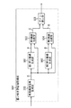
図1は、撮像装置の構成の一例を示すブロック図である。
図1において、結像光学部100を通って入射した被写体像を撮像素子101で撮像し、電気信号に光電変換する。A/D変換部102は、撮像素子101から出力された電気信号をデジタル信号に変換するものである。このように、本実施形態では、例えば、撮像素子101を用いて撮像手段が実現される。
(First embodiment)
Next, a first embodiment of the present invention will be described with reference to the drawings.
FIG. 1 is a block diagram illustrating an example of the configuration of the imaging apparatus.
In FIG. 1, a subject image incident through the imaging
現像処理部103では、A/D変換部102から出力されたデジタル信号を、YUVデータ形式の画像データに変換する。現像処理部103は、主にWB(White Balance)回路、ガンマ(γ)補正回路、及びマトリクス変換回路を備えている。覆い焼き評価値取得部104は、A/D変換部102から出力されたデジタル信号(画像信号)簡易輝度信号を生成し、この簡易輝度信号を用いて原画像に施す覆い焼き処理の評価値を算出する。具体的に、覆い焼き評価値取得部104は、A/D変換部102から出力されたデジタル信号(画像信号)であるRGB信号のうちG信号のみを使用して、Y信号を簡易輝度信号として生成する。尚、覆い焼き処理とは、デジタル画像の輝度のダイナミックレンジを狭める(平滑化する)ための信号処理をいい、覆い焼き処理の評価値とは、デジタル画像の輝度のダイナミックレンジを狭める(平滑化する)ためのデジタル画像の輝度の補正値をいう。
The
ここで、覆い焼き処理の具体例について詳細に説明する。
本実施形態では、原画像の輝度のダイナミックレンジを調整する技術を例に挙げて説明する。すなわち、原画像の画像信号を生成すると共に、この原画像からボケ画像の信号(以下、ボケ画像信号と称する)を生成し、それら原画像の画像信号とボケ画像信号との互いに対応する画素に対して演算を行ってそれらの画素の差分信号を生成する。そして、本実施形態では、生成した差分信号に対して所定の画像処理を施して原画像の輝度のダイナミックレンジを調整する場合を例に挙げて説明する。
Here, a specific example of the dodging process will be described in detail.
In the present embodiment, a technique for adjusting the dynamic range of the luminance of the original image will be described as an example. That is, an image signal of the original image is generated, and a signal of a blurred image (hereinafter referred to as a blurred image signal) is generated from the original image, and the image signal of the original image and the blurred image signal are assigned to corresponding pixels. An operation is performed on the pixel to generate a differential signal of those pixels. In this embodiment, a case where the generated difference signal is subjected to predetermined image processing to adjust the dynamic range of the luminance of the original image will be described as an example.
図2は、図1における覆い焼き評価値取得部104の内部構成の一例を詳細に示したブロック図である。
図2において、簡易輝度信号生成部500は、図1に示したA/D変換部102から出力された画像信号を基に簡易輝度信号Eを生成する。前述したように、簡易輝度信号生成部500は、A/D変換部102から出力された画像信号であるRGB信号の一部の信号(G信号)のみを使用してY信号を簡易輝度信号Eとして生成する。
FIG. 2 is a block diagram showing in detail an example of the internal configuration of the dodging evaluation
In FIG. 2, a simple luminance
第1ボケ画像生成部501は、簡易輝度信号生成部500で生成された簡易輝度信号Eを基に、簡易輝度信号Eのボケ画像信号であって、簡易輝度信号Eより解像度の低いボケ画像信号Aを生成する。第2ボケ画像生成部502は、簡易輝度信号生成部500から出力された簡易輝度信号Eを基に、簡易輝度信号Eのボケ画像信号であって、ボケ画像信号Aよりもさらに解像度の低いボケ画像信号Bを生成する。このように、本実施形態では、例えば、ボケ画像信号A、Bによって、簡易輝度信号(画像信号)を低解像度化した複数の画像信号であって、互いに解像度が異なる複数の画像信号が実現される。
The first blur
第1画像比較部503は、簡易輝度信号生成部500から出力された簡易輝度信号Eと、第1ボケ画像生成部501から出力されたボケ画像信号Aとの互いに対応する画素毎に、簡易画像信号Eとボケ画像信号Aとの差分値情報Cが求められる。
第2画像比較部504は、簡易輝度信号生成部500から出力された簡易輝度信号Eと、第2ボケ画像生成部502から出力されたボケ画像信号Bとの互いに対応する画素毎に、簡易画像信号Eとボケ画像信号Bとの差分値情報Dが求められる。
The first
The second
ゲイン算出部505は、第1画像比較部503から出力された差分値情報Cと、第2画像比較部504から出力された差分値情報Dとを用いて、原画像の各画素の輝度値に掛けられるゲイン係数を求め、求めたゲイン係数を覆い焼き評価値として出力する。
以上のように本実施形態では、例えば、ゲイン係数によって画像信号の輝度の補正値が実現され、覆い焼き評価値取得部104を用いて補正値導出手段が実現される。
The
As described above, in the present embodiment, for example, the correction value of the luminance of the image signal is realized by the gain coefficient, and the correction value deriving unit is realized by using the dodging evaluation
図1に説明を戻し、覆い焼き補正部105は、現像処理部103から出力される画像データと、覆い焼き評価値取得部104から出力された覆い焼き評価値とを基に、以下の処理を行う。すなわち、覆い焼き補正部105は、ボケ画像において輝度が明るい領域は画像データのゲインを下げ、ボケ画像において輝度が暗い領域は画像データのゲインを上げることで画像データ全体のダイナミックレンジを平滑化(狭く)する(覆い焼き処理を行う)。覆い焼き処理が施された画像データは、色変換処理部106へ送られる。
Returning to FIG. 1, the
操作部112は、色変換を行う任意の色をユーザが指定できるようにするためのシステムの入力手段である。具体的に操作部112は、例えば、ボタン、スイッチ、及びダイヤル等を備えている。ユーザは、表示部110によって表示装置(EVF)に表示された画像を確認しながら操作部112を操作して色変換を行う色を指定する。
The
色変換処理部106は、覆い焼き補正部105から入力された画像データに対して、操作部112の操作によって指定された色情報を基に、変換する色情報をLUT107から読み出して色変換処理を行う。尚、LUT107は、例えば、撮像装置に設けられたハードディスク、EEPROM、又はROMに格納されている。
ここで、色変換処理部106が行う色変換の一例について説明する。まず、色変換処理部106は、入力された画像データを、YUV信号からRGB信号に変換する。変換されたRGB信号のR、G、Bの各色成分における信号値が、LUT107から色変換マトリックス情報を読み出すためのアドレスとなる。例えば、RGB信号のR、G、Bの各色成分における信号値(色変換マトリックス情報の値)が、夫々18、20、30(R=18、G=20、B=30)とする。この場合、色変換処理部106は、その信号値をアドレス(X=18、Y=20、Z=23)とし、そのアドレスに対応する別の色変換マトリックス情報(例えば、R´=40、G´=10、B´=23)をLUT107から読み出すことになる。
The color
Here, an example of color conversion performed by the color
色変換処理部106は、このようにして読み出した色変換マトリックス情報を基に、RGB信号の各色成分のゲインを調整して色変換を行う。色変換処理部106は、色変換を行った後、RGB信号からYUV信号に信号形式を戻す。こうして、入力された画像データの色変換処理を終える。以上のように本実施形態では、例えば、覆い焼き補正部105を用いて平滑化手段が実現される。
The color
色変換処理部106によって色変換された画像データは、メモリI/F108を介してメモリ109に格納される。メモリ109は、例えば、RAM、EEPROM、又はハードディスクを用いて構成することができる。また、メモリ109は、リムーバルメディア等の外部記録媒体であってもよい。
以上のように本実施形態では、例えば、色変換処理部106を用いて色変換手段が実現される。
The image data color-converted by the color
As described above, in this embodiment, for example, a color conversion unit is realized using the color
表示部110は、メモリ109に格納された画像データをメモリI/F108を介して読み出し、LCD(Liquid Crystal Display)等の表示装置(EVF)に画像を表示する。ユーザは、この表示装置に表示される画像、すなわち、覆い焼き処理が行われた後の画像、又は覆い焼き処理と色変換処理とが行われた後の画像を確認しながら撮影を指示する。ユーザが、シャッターボタンといった撮影記録ボタンを押して撮影を指示すると、覆い焼き処理が行われた画像データ、又は覆い焼き処理と色変換処理とが行われた画像データが、メモリI/F108を介してメモリ109に記録される。尚、JPEG等の圧縮形式で圧縮してから画像データをメモリ109に記録しても良い。
The
ここで、図3のフローチャートを参照しながら、撮影時に画像データの色変換を行う際の撮像装置における動作の一例を説明する。
操作部112の操作によって、撮像装置の電源がON状態になると、図3のフローチャートがスタートする。
まず、ステップS100において、CPU111は、操作部112の操作内容を判断することによって、撮影モードがONであるか否かを判別する。この判別の結果、撮影モードがOFFの場合は、ステップS110へ進み、CPU111は、撮像装置の電源がONか否かを判別する。この判別の結果、撮像装置の電源がONであれば、ステップS100に戻る。一方、撮像装置の電源がOFFであれば、処理を終了する。
Here, an example of the operation of the imaging apparatus when performing color conversion of image data during shooting will be described with reference to the flowchart of FIG.
When the power of the imaging apparatus is turned on by the operation of the
First, in step S100, the
ステップS100において、撮影モードがONであれば、ステップS101に進む。ステップS101では、覆い焼き評価値取得部104は、覆い焼き評価値を算出する。具体的に説明すると、前述したように、覆い焼き評価値取得部104は、A/D変換部102から出力された画像信号を基に簡易輝度信号Eを生成し、生成した簡易輝度信号Eを基に、ボケ画像信号A、Bを生成する。そして、覆い焼き評価値取得部104は、簡易画像信号Eとボケ画像信号Aとの差分値情報Cを求めると共に、簡易画像信号Eとボケ画像信号Bとの差分値情報Dを求め、差分値情報C、Dを用いて、原画像の各画素に掛けられるゲイン係数を求める。そして、覆い焼き評価値取得部104は、求めたゲイン係数を覆い焼き評価値として出力する。
If the shooting mode is ON in step S100, the process proceeds to step S101. In step S101, the dodging evaluation
次に、ステップS102において、覆い焼き補正部105は、覆い焼き評価値取得部104から出力された覆い焼き評価値を用いて、現像処理部103から出力される画像データに対して覆い焼き処理を行う。具体的に覆い焼き補正部105は、ボケ画像において輝度が相対的に高い明るい領域については、画像データのゲインを下げ、ボケ画像において輝度が相対的に低い暗い領域については、画像データのゲインを上げる。このようにすることによって、画像データ全体のダイナミックレンジが平滑化される。
In step S <b> 102, the
次に、ステップS103において、CPU111は、ステップS103で覆い焼き処理が施された画像データを、LCD等の表示装置に表示させることを表示部110に指示する。これにより、覆い焼き処理が施された画像データが表示装置(EVF)に表示される。
次に、ステップS104において、CPU111は、例えば操作部112の操作内容に基づいて、色変換機能がONか否かを判別する。この判別の結果、色変換機能がOFFであれば、ステップS105〜S107を省略して後述するステップS108に進む。
一方、色変換機能がONであれば、ステップS105に進む。ステップS105では、CPU111は、操作部112の操作によってユーザが指定した色情報を取得する。すなわち、CPU111は、色変換の対象となる色の情報を取得する。
Next, in step S103, the
Next, in step S104, the
On the other hand, if the color conversion function is ON, the process proceeds to step S105. In step S <b> 105, the
次に、ステップS106において、色変換処理部106は、ステップS105で取得された色情報を基に、ステップS102で覆い焼き処理が施された画像データに対して色変換処理を行う。
次に、ステップS107において、CPU111は、ステップS106で色変換処理が施された画像データを、LCD等の表示装置に表示させることを表示部110に指示する。これにより、覆い焼き処理が施された後に色変換処理が施された画像データが表示装置(EVF)に表示される。
Next, in step S106, the color
Next, in step S107, the
ステップS108に進むと、CPU111は、例えば操作部112の操作内容に基づいて、シャッターボタンが押されたか否かを判別する。この判別の結果、シャッターボタンが押されていなければ、後述するステップS109を省略してステップS110に進む。一方、シャッターボタンが押されれば、ステップS109に進み、CPU111は、覆い焼き処理が施された画像データ、又は覆い焼き処理が施された後に色変換処理が施された画像データをメモリ109に記録する。
次に、ステップS110に進み、CPU111は、前述したように、撮像装置の電源がONか否かを判別する。この判別の結果、撮像装置の電源がONであれば、ステップS100に戻る。一方、撮像装置の電源がOFFであれば、処理を終了する。
In step S108, the
Next, proceeding to step S110, the
以上のように本実施形態では、覆い焼き評価値取得部104は、A/D変換部102から出力された画像信号を基に簡易輝度信号Eを生成し、生成した簡易輝度信号Eを基に、ボケ画像信号A、Bを生成する。そして、覆い焼き評価値取得部104は、簡易画像信号Eとボケ画像信号Aとの差分値情報Cと、簡易画像信号Eとボケ画像信号Bとの差分値情報Dとを求め、差分値情報C、Dを用いて、原画像の各画素の輝度値に掛けられるゲイン係数を求める。覆い焼き補正部105は、覆い焼き評価値取得部104で求められたゲイン係数を覆い焼き評価値として用いて、ボケ画像において輝度が高い領域については画像データのゲインを下げ、ボケ画像において輝度が暗い領域については画像データのゲインを上げる。これにより、画像データ全体のダイナミックレンジを狭め(平滑化し)、覆い焼き処理(補正)が行われる。
As described above, in the present embodiment, the dodging evaluation
表示部110は、このようにして覆い焼き処理が施された画像データを、表示装置(EVF)に表示する。色変換処理部106は、表示した画像データに対してユーザにより指定された色情報に基づいて、以上のようにして覆い焼き処理が行われた画像データに対して色変換処理を行う。そして、表示部110は、色変換処理が施された画像データを、表示装置(EVF)に表示する。
The
以上のように本実施形態では、画像データに対して、覆い焼き処理を行った後に色変換処理を行うようにしたので、色変換処理を行う際には、対象物のAEレベルが可及的に適正に補正された状態にすることができる。すなわち、色変換の対象物の明るさを略一定にした状態で色変換処理を行うことができる。従って、ダイナミックレンジが広いシーンにおける撮影であっても色変換のばらつきを抑えることができる。
また、本実施形態では、EVF表示される画像データにおいても、AEレベルが補正された後に色変換処理を行った画像データをEVF表示することができる。従って、ユーザは、AEレベルが補正された後に色変換処理を行った画像データを見ながら、色指定を行うことができる。
As described above, in the present embodiment, the color conversion process is performed after the dodging process is performed on the image data. Therefore, when the color conversion process is performed, the AE level of the target is as much as possible. Can be properly corrected. That is, the color conversion process can be performed in a state where the brightness of the color conversion object is substantially constant. Therefore, variation in color conversion can be suppressed even when shooting in a scene with a wide dynamic range.
In the present embodiment, image data that has undergone color conversion processing after the AE level is corrected can be displayed in EVF even in image data that is displayed in EVF. Therefore, the user can specify the color while viewing the image data that has been subjected to the color conversion processing after the AE level is corrected.
また、本実施形態では、A/D変換部102から出力された画像信号を基に簡易輝度信号Eを生成し、この簡易輝度信号Eを用いて覆い焼き評価値を算出するようにしたので、覆い焼き評価値を取得するための回路規模を小さくすることができる。
また、本実施形態では、互いに空間的な周波数帯域の異なる複数のボケ画像A、Bを用いて覆い焼き評価値を算出するようにした。すなわち、簡易輝度信号Eより解像度が低い「簡易輝度信号Eのボケ画像A」と、ボケ画像Aよりも更に解像度が低い「簡易輝度信号Eのボケ画像B」とを生成し、それらボケ画像A、Bを用いて覆い焼き評価値を算出するようにした。従って、画像の明るい個所と暗い個所との境界部分の処理でも違和感の生じない覆い焼き処理を施すことが可能となる。すなわち、ボケ画像Aによって局所的なダイナミックレンジを補正することができる反面、そのボケ画像Aによってダイナミックレンジが補正された部分が浮き出たような印象の画像となってしまう。そこで、ボケ画像Bを用いて広い領域のダイナミックレンジを補正することによって、前記浮き出たような印象を与えてしまう部分を可及的に自然な印象にすることができる。
In the present embodiment, the simple luminance signal E is generated based on the image signal output from the A /
In the present embodiment, the dodging evaluation value is calculated using a plurality of blurred images A and B having different spatial frequency bands. That is, the “blurred image A of the simple luminance signal E” having a lower resolution than the simple luminance signal E and the “blurred image B of the simple luminance signal E” having a lower resolution than the blurred image A are generated. , B were used to calculate the dodging evaluation value. Therefore, it is possible to perform a dodging process that does not cause a sense of incongruity even in the process of the boundary portion between the bright part and the dark part of the image. That is, while the local dynamic range can be corrected by the blurred image A, the image has an impression that a portion where the dynamic range is corrected by the blurred image A is raised. Therefore, by correcting the dynamic range of a wide area using the blurred image B, it is possible to make the portion that gives the impression of being raised as natural as possible.
(第2の実施形態)
次に、本発明の第2の実施形態について説明する。前述した第1の実施形態では、覆い焼き処理が行われる前に、現像処理部103の中で画像データのガンマ(γ)補正を行うようにした場合を例に挙げて説明した。これに対して本実施形態では、覆い焼き処理が行われ、ダイナミックレンジが平滑化された画像データに対してガンマ(γ)補正を行うようにする場合を例に挙げて説明する。このように本実施形態と前述した第1の実施形態とは、画像データの処理の一部が異なるだけであるので、本実施形態の説明において、前述した第1の実施形態と同一の部分については、図1〜図3に付した符号を付す等して詳細な説明を省略する。
図4は、撮像装置の構成の一例を示すブロック図である。
図4において、結像光学部100を通って入射した被写体像は、撮像素子101で電気信号に光電変換され、その電気信号は、A/D変換部102でデジタル信号に変換される。現像処理部203は、A/D変換部102から出力されたデジタル信号を、YUVデータ形式の画像データに変換するために、主にWB回路、及びマトリクス変換回路を備えている。図1に示した現像処理部103にはガンマ(γ)補正回路が設けられていたが、本実施形態の現像処理部203にはガンマ(γ)補正回路は設けられていない。
(Second Embodiment)
Next, a second embodiment of the present invention will be described. In the first embodiment described above, the case where the gamma (γ) correction of the image data is performed in the
FIG. 4 is a block diagram illustrating an example of the configuration of the imaging apparatus.
In FIG. 4, a subject image incident through the imaging
覆い焼き評価値取得部104は、第1の実施形態で説明したようにして覆い焼き処理の評価値を取得する。覆い焼き補正部105は、現像処理部103から出力される画像データと、覆い焼き評価値取得部104から出力された覆い焼き評価値とを基に、覆い焼き処理を行う。覆い焼き処理が施された画像データは、ガンマ補正部213へ送られる。この覆い焼き処理の評価値の取得と、覆い焼き処理とは、第1の実施形態で説明したのと同じ方法で実現される。
The dodging evaluation
ガンマ補正部213は、覆い焼き処理が施され、ダイナミックレンジが平滑化された画像データに対して、ガンマ(γ)補正処理を行う。第1の実施形態とは異なり、覆い焼き処理が施された後にガンマ補正を行うことで、人間が実際のシーンを見たときの印象により近い画像を出力することができる。ガンマ補正部213から出力される画像データは色変換処理部106へ送られる。以上のように本実施形態では、例えば、ガンマ補正部213を用いてガンマ補正手段が実現される。
The
そして、CPU111は、覆い焼き処理が施された後にガンマ補正が施された画像データを、LCD等の表示装置に表示させることを表示部110に指示する。これにより、覆い焼き処理が施された後にガンマ補正が施された画像データが表示装置(EVF)に表示される。
Then, the
色変換処理部106は、ガンマ補正部213から入力された画像データに対して、操作部112の操作によって指定された色情報を基に、変換する色情報をLUT107から読み出して色変換処理を行う。この色変換処理は、第1の実施形態で説明したのと同じ方法で実現される。
そして、CPU111は、色変換処理が施された画像データを、LCD等の表示装置に表示させることを表示部110に指示する。これにより、色変換処理が施された画像データが表示装置(EVF)に表示される。
The color
Then, the
以上のように本実施形態では、覆い焼き処理が施された画像データに対してガンマ補正を行うようにした。したがって、ノイズを増やすことなく暗部(低輝度部)のゲインを上げることができ、更に明部(高輝度部)のゲインを下げる場合も擬似輪郭を発生させずに高いSN比で覆い焼き処理を施すことができる。このため、人間が実際のシーンを見たときの印象により近い状態の画像に対して色変換処理を行うことが可能となる。すなわち、より自然な画像を基に色変換処理が行うことが可能となる。 As described above, in this embodiment, gamma correction is performed on image data that has been subjected to dodging processing. Therefore, the gain of the dark part (low luminance part) can be increased without increasing the noise, and the dodging process can be performed with a high SN ratio without generating a pseudo contour even when the gain of the bright part (high luminance part) is further reduced. Can be applied. For this reason, it is possible to perform color conversion processing on an image that is closer to an impression when a human sees an actual scene. That is, color conversion processing can be performed based on a more natural image.
(本発明の他の実施形態)
前述した本発明の実施形態における撮像装置を構成する各手段、並びに撮像処理方法の各ステップは、コンピュータのRAMやROMなどに記憶されたプログラムが動作することによって実現できる。このプログラム及び前記プログラムを記録したコンピュータ読み取り可能な記録媒体は本発明に含まれる。
(Other embodiments of the present invention)
Each unit constituting the imaging apparatus and each step of the imaging processing method in the embodiment of the present invention described above can be realized by operating a program stored in a RAM or a ROM of a computer. This program and a computer-readable recording medium recording the program are included in the present invention.
また、本発明は、例えば、システム、装置、方法、プログラム若しくは記憶媒体等としての実施形態も可能であり、具体的には、複数の機器から構成されるシステムに適用してもよいし、また、一つの機器からなる装置に適用してもよい。 In addition, the present invention can be implemented as, for example, a system, apparatus, method, program, storage medium, or the like. Specifically, the present invention may be applied to a system including a plurality of devices. The present invention may be applied to an apparatus composed of a single device.
なお、本発明は、前述した実施形態の機能を実現するソフトウェアのプログラム(実施形態では図3に示すフローチャートに対応したプログラム)を、システムあるいは装置に直接、あるいは遠隔から供給する。そして、そのシステムあるいは装置のコンピュータが前記供給されたプログラムコードを読み出して実行することによっても達成される場合を含む。 In the present invention, a software program (in the embodiment, a program corresponding to the flowchart shown in FIG. 3) that realizes the functions of the above-described embodiments is directly or remotely supplied to a system or apparatus. In addition, this includes a case where the system or the computer of the apparatus is also achieved by reading and executing the supplied program code.
したがって、本発明の機能処理をコンピュータで実現するために、前記コンピュータにインストールされるプログラムコード自体も本発明を実現するものである。つまり、本発明は、本発明の機能処理を実現するためのコンピュータプログラム自体も含まれる。 Accordingly, since the functions of the present invention are implemented by computer, the program code installed in the computer also implements the present invention. In other words, the present invention includes a computer program itself for realizing the functional processing of the present invention.
その場合、プログラムの機能を有していれば、オブジェクトコード、インタプリタにより実行されるプログラム、OSに供給するスクリプトデータ等の形態であってもよい。 In that case, as long as it has the function of a program, it may be in the form of object code, a program executed by an interpreter, script data supplied to the OS, and the like.
プログラムを供給するための記録媒体としては、例えば、フロッピー(登録商標)ディスク、ハードディスク、光ディスク、光磁気ディスク、MO、CD−ROM、CD−R、CD−RWなどがある。また、磁気テープ、不揮発性のメモリカード、ROM、DVD(DVD−ROM,DVD−R)などもある。 Examples of the recording medium for supplying the program include a floppy (registered trademark) disk, hard disk, optical disk, magneto-optical disk, MO, CD-ROM, CD-R, and CD-RW. In addition, there are magnetic tape, nonvolatile memory card, ROM, DVD (DVD-ROM, DVD-R), and the like.
その他、プログラムの供給方法としては、クライアントコンピュータのブラウザを用いてインターネットのホームページに接続する。そして、前記ホームページから本発明のコンピュータプログラムそのもの、若しくは圧縮され自動インストール機能を含むファイルをハードディスク等の記録媒体にダウンロードすることによっても供給できる。 As another program supply method, a browser on a client computer is used to connect to an Internet home page. The computer program itself of the present invention or a compressed file including an automatic installation function can be downloaded from the homepage by downloading it to a recording medium such as a hard disk.
また、本発明のプログラムを構成するプログラムコードを複数のファイルに分割し、それぞれのファイルを異なるホームページからダウンロードすることによっても実現可能である。つまり、本発明の機能処理をコンピュータで実現するためのプログラムファイルを複数のユーザに対してダウンロードさせるWWWサーバも、本発明に含まれるものである。 It can also be realized by dividing the program code constituting the program of the present invention into a plurality of files and downloading each file from a different homepage. That is, a WWW server that allows a plurality of users to download a program file for realizing the functional processing of the present invention on a computer is also included in the present invention.
また、本発明のプログラムを暗号化してCD−ROM等の記憶媒体に格納してユーザに配布し、所定の条件をクリアしたユーザに対し、インターネットを介してホームページから暗号化を解く鍵情報をダウンロードさせる。そして、ダウンロードした鍵情報を使用することにより暗号化されたプログラムを実行してコンピュータにインストールさせて実現することも可能である。 In addition, the program of the present invention is encrypted, stored in a storage medium such as a CD-ROM, distributed to users, and key information for decryption is downloaded from a homepage via the Internet to users who have cleared predetermined conditions. Let It is also possible to execute the encrypted program by using the downloaded key information and install the program on a computer.
また、コンピュータが、読み出したプログラムを実行することによって、前述した実施形態の機能が実現される。その他、そのプログラムの指示に基づき、コンピュータ上で稼動しているOSなどが、実際の処理の一部又は全部を行い、その処理によっても前述した実施形態の機能が実現され得る。 Further, the functions of the above-described embodiments are realized by the computer executing the read program. In addition, based on the instructions of the program, an OS or the like running on the computer performs part or all of the actual processing, and the functions of the above-described embodiments can also be realized by the processing.
さらに、記録媒体から読み出されたプログラムが、コンピュータに挿入された機能拡張ボードやコンピュータに接続された機能拡張ユニットに備わるメモリに書き込まれる。その後、そのプログラムの指示に基づき、その機能拡張ボードや機能拡張ユニットに備わるCPUなどが実際の処理の一部又は全部を行い、その処理によっても前述した実施形態の機能が実現される。 Further, the program read from the recording medium is written in a memory provided in a function expansion board inserted into the computer or a function expansion unit connected to the computer. Thereafter, the CPU of the function expansion board or function expansion unit performs part or all of the actual processing based on the instructions of the program, and the functions of the above-described embodiments are realized by the processing.
なお、前述した各実施形態は、何れも本発明を実施するにあたっての具体化の例を示したものに過ぎず、これらによって本発明の技術的範囲が限定的に解釈されてはならないものである。すなわち、本発明はその技術思想、又はその主要な特徴から逸脱することなく、様々な形で実施することができる。 Note that each of the above-described embodiments is merely a specific example for carrying out the present invention, and the technical scope of the present invention should not be construed as being limited thereto. . That is, the present invention can be implemented in various forms without departing from the technical idea or the main features thereof.
103、203 現像処理部
104 覆い焼き評価値
105 覆い焼き補正部
106 色変換処理部
107 LUT
109 メモリ
110 表示部
111 CPU
112 操作部
213 ガンマ補正部
103, 203
109
112
Claims (12)
前記撮像手段により撮像された被写体像に基づく輝度信号Yを複数の周波数成分に分けて求めた評価結果に応じて輝度信号Yのダイナミックレンジを平滑化する平滑化手段と、
前記平滑化手段により輝度のダイナミックレンジが平滑化された輝度信号Yに対してガンマ補正を行うガンマ補正手段と、
前記平滑化手段によりダイナミックレンジが平滑化され前記ガンマ補正手段によってガンマ補正が行われた後の輝度信号Yと色差信号U及びVとから生成することができる色信号R,G,及びBで構成される色であって、ユーザ操作に応じて特定された色に対して色変換を行う色変換手段と、
前記平滑化手段によりダイナミックレンジが平滑化され前記ガンマ補正手段によってガンマ補正が行われた輝度信号Yに基づく画像と、更に前記色変換手段により色が変換された画像信号に基づく画像とを表示装置に表示する表示手段と、を有することを特徴とする撮像装置。 Imaging means for capturing a subject image;
Smoothing means for smoothing the dynamic range of the luminance signal Y according to the evaluation result obtained by dividing the luminance signal Y based on the subject image captured by the imaging means into a plurality of frequency components;
Gamma correction means for performing gamma correction on the luminance signal Y whose luminance dynamic range is smoothed by the smoothing means;
It comprises color signals R, G, and B that can be generated from the luminance signal Y and the color difference signals U and V after the dynamic range is smoothed by the smoothing means and the gamma correction is performed by the gamma correction means. Color conversion means for performing color conversion on a color specified in response to a user operation,
A display device that displays an image based on the luminance signal Y smoothed by the smoothing means and subjected to gamma correction by the gamma correction means, and an image based on the image signal whose color has been converted by the color conversion means. And an image display device.
前記平滑化手段は、前記補正値導出手段により求められた補正値を用いて、輝度信号Yのダイナミックレンジを平滑化することを特徴とする請求項1に記載の撮像装置。 Correction value deriving means for obtaining a correction value of the luminance signal Y based on the subject image imaged by the imaging means;
The imaging apparatus according to claim 1, wherein the smoothing unit smoothes the dynamic range of the luminance signal Y using the correction value obtained by the correction value deriving unit.
前記色変換手段は、前記平滑化手段によりダイナミックレンジが平滑化された後の輝度信号Yと色差信号U及びVとから生成することができる色信号R,G,及びBで構成される色であって、前記操作手段の操作に基づいてユーザによって指定された色を変換することを特徴とする請求項1〜5の何れか1項に記載の撮像装置。 An operation means for the user to specify the color of the image signal displayed by the display means;
The color conversion means is a color composed of color signals R, G, and B that can be generated from the luminance signal Y and the color difference signals U and V after the dynamic range is smoothed by the smoothing means. 6. The imaging apparatus according to claim 1, wherein a color designated by a user is converted based on an operation of the operation means.
前記撮像ステップにより撮像された被写体像に基づく輝度信号Yを複数の周波数成分に分けて求めた評価結果に応じて輝度信号Yのダイナミックレンジを平滑化する平滑化ステップと、
前記平滑化ステップにより輝度のダイナミックレンジが平滑化された輝度信号Yに対してガンマ補正を行うガンマ補正ステップと、
前記平滑化ステップによりダイナミックレンジが平滑化され前記ガンマ補正ステップによってガンマ補正が行われた後の輝度信号Yと色差信号U及びVとから生成することができる色信号R,G,及びBで構成される色であって、ユーザ操作に応じて特定された色に対して色変換を行う色変換ステップと、
前記平滑化ステップによりダイナミックレンジが平滑化され前記ガンマ補正ステップによってガンマ補正が行われた画像信号に基づく画像と、更に前記色変換ステップにより色が変換された画像信号に基づく画像とを表示装置に表示する表示ステップと、を有することを特徴とする撮像処理方法。 An imaging step for imaging a subject image;
A smoothing step of smoothing a dynamic range of the luminance signal Y according to an evaluation result obtained by dividing the luminance signal Y based on the subject image captured by the imaging step into a plurality of frequency components;
A gamma correction step of performing gamma correction on the luminance dynamic range of the smoothing step is smoothed Brightness signal Y,
It comprises color signals R, G, and B that can be generated from the luminance signal Y and the color difference signals U and V after the dynamic range is smoothed by the smoothing step and the gamma correction is performed by the gamma correction step. A color conversion step for performing color conversion on a color specified in response to a user operation,
An image based on the image signal in which the dynamic range is smoothed by the smoothing step and the gamma correction is performed by the gamma correction step, and an image based on the image signal whose color is converted by the color conversion step are displayed on a display device. And a display step for displaying. An imaging processing method comprising:
前記平滑化ステップは、前記補正値導出ステップにより求められた補正値を用いて、輝度信号Yのダイナミックレンジを平滑化することを特徴とする請求項7に記載の撮像処理方法。 A correction value deriving step for obtaining a correction value of the luminance of the luminance signal Y based on the subject image captured by the imaging step;
The imaging processing method according to claim 7, wherein the smoothing step smoothes the dynamic range of the luminance signal Y using the correction value obtained in the correction value deriving step.
前記色変換ステップは、前記平滑化ステップによりダイナミックレンジが平滑化された後の輝度信号Yと色差信号U及びVとから生成することができる色信号R,G,及びBで構成される色であって、前記操作ステップの操作に基づいてユーザによって指定された色を変換することを特徴とする請求項7〜11の何れか1項に記載の撮像処理方法。 An operation step for the user to specify the color of the image signal displayed by the display step;
The color conversion step is a color composed of color signals R, G, and B that can be generated from the luminance signal Y and the color difference signals U and V after the dynamic range is smoothed by the smoothing step. The imaging processing method according to claim 7, wherein a color designated by a user is converted based on an operation of the operation step.
Priority Applications (3)
| Application Number | Priority Date | Filing Date | Title |
|---|---|---|---|
| JP2007004767A JP5054981B2 (en) | 2007-01-12 | 2007-01-12 | Imaging apparatus and imaging processing method |
| US11/969,760 US8094205B2 (en) | 2007-01-12 | 2008-01-04 | Imaging apparatus, image processing method and computer program for smoothing dynamic range of luminance of an image signal, color conversion process |
| US13/346,211 US8957991B2 (en) | 2007-01-12 | 2012-01-09 | Imaging apparatus, image processing method and computer program for smoothing dynamic range of luminance of an image signal, color conversion process |
Applications Claiming Priority (1)
| Application Number | Priority Date | Filing Date | Title |
|---|---|---|---|
| JP2007004767A JP5054981B2 (en) | 2007-01-12 | 2007-01-12 | Imaging apparatus and imaging processing method |
Publications (3)
| Publication Number | Publication Date |
|---|---|
| JP2008172610A JP2008172610A (en) | 2008-07-24 |
| JP2008172610A5 JP2008172610A5 (en) | 2010-11-25 |
| JP5054981B2 true JP5054981B2 (en) | 2012-10-24 |
Family
ID=39700270
Family Applications (1)
| Application Number | Title | Priority Date | Filing Date |
|---|---|---|---|
| JP2007004767A Expired - Fee Related JP5054981B2 (en) | 2007-01-12 | 2007-01-12 | Imaging apparatus and imaging processing method |
Country Status (2)
| Country | Link |
|---|---|
| US (2) | US8094205B2 (en) |
| JP (1) | JP5054981B2 (en) |
Families Citing this family (7)
| Publication number | Priority date | Publication date | Assignee | Title |
|---|---|---|---|---|
| JP4314305B1 (en) * | 2008-02-04 | 2009-08-12 | シャープ株式会社 | Sharpening image processing apparatus, method, and software |
| JP5093364B2 (en) * | 2008-12-26 | 2012-12-12 | 富士通株式会社 | Image processing system, image processing apparatus, and image processing method |
| US9077905B2 (en) * | 2009-02-06 | 2015-07-07 | Canon Kabushiki Kaisha | Image capturing apparatus and control method thereof |
| US8355059B2 (en) * | 2009-02-06 | 2013-01-15 | Canon Kabushiki Kaisha | Image capturing apparatus and control method thereof |
| DE102010041569B4 (en) * | 2010-09-28 | 2017-04-06 | Leica Geosystems Ag | Digital camera system, color filter element for digital camera system, method for determining deviations between the cameras of a digital camera system and image processing unit for digital camera system |
| JP2012095200A (en) * | 2010-10-28 | 2012-05-17 | Canon Inc | Image processing device, image processing method, and program |
| JP5574015B2 (en) * | 2013-05-27 | 2014-08-20 | 株式会社ニコン | Image processing apparatus, electronic camera, and image processing program |
Family Cites Families (22)
| Publication number | Priority date | Publication date | Assignee | Title |
|---|---|---|---|---|
| EP0669753A3 (en) * | 1994-02-28 | 1995-12-20 | Minolta Co Ltd | An apparatus for reproducing images. |
| US5835627A (en) * | 1995-05-15 | 1998-11-10 | Higgins; Eric W. | System and method for automatically optimizing image quality and processing time |
| KR100422943B1 (en) * | 1996-07-31 | 2004-03-12 | 마츠시타 덴끼 산교 가부시키가이샤 | Picture encoder, picture decoder, picture encoding method, picture decoding method, and medium |
| JP3581270B2 (en) * | 1999-03-26 | 2004-10-27 | ノーリツ鋼機株式会社 | Image processing apparatus, image processing method, and recording medium recording image processing program |
| JP2001257902A (en) | 2000-03-13 | 2001-09-21 | Fuji Photo Film Co Ltd | Method and device for processing image |
| JP2002016874A (en) * | 2000-04-28 | 2002-01-18 | Fuji Photo Film Co Ltd | Method and apparatus for processing image as well as recording medium for recording program therefor |
| JP2001358983A (en) * | 2000-06-14 | 2001-12-26 | Ricoh Co Ltd | Image input device, image recording method, and computer-readable recording medium for storing program to perform the method |
| US6873729B2 (en) * | 2000-07-14 | 2005-03-29 | Ricoh Company, Ltd. | Method, apparatus and computer program product for processing image data |
| JP2002092607A (en) * | 2000-07-14 | 2002-03-29 | Ricoh Co Ltd | Image processor, image state determining method and recording medium |
| JP2002152541A (en) * | 2000-11-16 | 2002-05-24 | Nikon Corp | Image processor and image processing recording medium |
| JP2004248061A (en) * | 2003-02-14 | 2004-09-02 | Fuji Photo Film Co Ltd | Apparatus, method and program for image processing |
| SG115540A1 (en) * | 2003-05-17 | 2005-10-28 | St Microelectronics Asia | An edge enhancement process and system |
| JP2005210208A (en) * | 2004-01-20 | 2005-08-04 | Fuji Xerox Co Ltd | Image processor, image processing method, and program |
| KR100601942B1 (en) * | 2004-02-26 | 2006-07-14 | 삼성전자주식회사 | Method and apparatus for color transformation and multiple color display apparatus using the same |
| US7508993B2 (en) * | 2004-03-09 | 2009-03-24 | Microsoft Corporation | System and process for automatic exposure correction in an image |
| JP2006065676A (en) * | 2004-08-27 | 2006-03-09 | Canon Inc | Image processor and image processing method |
| JP2006179978A (en) * | 2004-12-20 | 2006-07-06 | Toshiba Corp | Video signal processor |
| US7525579B2 (en) * | 2004-12-27 | 2009-04-28 | Konica Minolta Holdings, Inc. | Image sensing apparatus and image processing method for use therein |
| WO2007010531A2 (en) * | 2005-07-19 | 2007-01-25 | Elbit Systems Electro-Optics Elop Ltd. | Method and system for visually presenting a high dynamic range image |
| JP4662356B2 (en) * | 2005-10-21 | 2011-03-30 | キヤノン株式会社 | Imaging apparatus and control method thereof, control program thereof, and storage medium storing control program |
| US8687087B2 (en) * | 2006-08-29 | 2014-04-01 | Csr Technology Inc. | Digital camera with selectively increased dynamic range by control of parameters during image acquisition |
| US20090213392A1 (en) * | 2007-12-28 | 2009-08-27 | Seiko Epson Corporation | Printing control device, printing system and printing control program |
-
2007
- 2007-01-12 JP JP2007004767A patent/JP5054981B2/en not_active Expired - Fee Related
-
2008
- 2008-01-04 US US11/969,760 patent/US8094205B2/en not_active Expired - Fee Related
-
2012
- 2012-01-09 US US13/346,211 patent/US8957991B2/en active Active
Also Published As
| Publication number | Publication date |
|---|---|
| US20120105667A1 (en) | 2012-05-03 |
| US8957991B2 (en) | 2015-02-17 |
| US8094205B2 (en) | 2012-01-10 |
| JP2008172610A (en) | 2008-07-24 |
| US20080211923A1 (en) | 2008-09-04 |
Similar Documents
| Publication | Publication Date | Title |
|---|---|---|
| US10412296B2 (en) | Camera using preview image to select exposure | |
| TWI293846B (en) | Image pickup device with brightness correcting function and method of correcting brightness of image | |
| JP4218723B2 (en) | Image processing apparatus, imaging apparatus, image processing method, and program | |
| JP5054981B2 (en) | Imaging apparatus and imaging processing method | |
| JP2004128809A (en) | Method and apparatus for image processing, and imaging device | |
| EP1679660B1 (en) | History adding device for generating history-added image file, electronic camera, and image processing program for processing history-added image file | |
| JP2012205244A (en) | Image processing device and method of controlling the same | |
| JP6624889B2 (en) | Video processing apparatus, video processing method, and video processing program | |
| JP2000020691A (en) | Image processing device and method, image-pickup device, control method, and storage medium therefor | |
| JP2017212532A (en) | Image processing apparatus | |
| JP2011228807A (en) | Image processing program, image processing apparatus, and image processing method | |
| JP5076650B2 (en) | Imaging apparatus and image processing program | |
| JP2002305684A (en) | Imaging system and program | |
| JP2006080942A (en) | Image processing apparatus, image processing program, image processing method, and imaging apparatus | |
| JP2002288650A (en) | Image processing device, digital camera, image processing method and recording medium | |
| JP2002092607A (en) | Image processor, image state determining method and recording medium | |
| JP5561389B2 (en) | Image processing program, image processing apparatus, electronic camera, and image processing method | |
| JP2012044377A (en) | Image compositing device, image compositing method and program | |
| JP5282533B2 (en) | Image processing apparatus, imaging apparatus, and program | |
| JP5315634B2 (en) | Image processing apparatus and image processing method | |
| JP7370762B2 (en) | Imaging device and its control method | |
| JP5739752B2 (en) | Image processing apparatus and imaging apparatus | |
| JP4826260B2 (en) | Imaging apparatus and program | |
| JP4978669B2 (en) | Image processing apparatus, electronic camera, and image processing program | |
| JP2004159087A (en) | Scanner system and image processing program |
Legal Events
| Date | Code | Title | Description |
|---|---|---|---|
| A621 | Written request for application examination |
Free format text: JAPANESE INTERMEDIATE CODE: A621 Effective date: 20100112 |
|
| A521 | Request for written amendment filed |
Free format text: JAPANESE INTERMEDIATE CODE: A523 Effective date: 20101007 |
|
| A871 | Explanation of circumstances concerning accelerated examination |
Free format text: JAPANESE INTERMEDIATE CODE: A871 Effective date: 20101007 |
|
| A975 | Report on accelerated examination |
Free format text: JAPANESE INTERMEDIATE CODE: A971005 Effective date: 20101014 |
|
| A131 | Notification of reasons for refusal |
Free format text: JAPANESE INTERMEDIATE CODE: A131 Effective date: 20101019 |
|
| A521 | Request for written amendment filed |
Free format text: JAPANESE INTERMEDIATE CODE: A523 Effective date: 20101117 |
|
| A02 | Decision of refusal |
Free format text: JAPANESE INTERMEDIATE CODE: A02 Effective date: 20101207 |
|
| A521 | Request for written amendment filed |
Free format text: JAPANESE INTERMEDIATE CODE: A523 Effective date: 20110304 |
|
| A911 | Transfer to examiner for re-examination before appeal (zenchi) |
Free format text: JAPANESE INTERMEDIATE CODE: A911 Effective date: 20110315 |
|
| A912 | Re-examination (zenchi) completed and case transferred to appeal board |
Free format text: JAPANESE INTERMEDIATE CODE: A912 Effective date: 20110422 |
|
| A521 | Request for written amendment filed |
Free format text: JAPANESE INTERMEDIATE CODE: A523 Effective date: 20120622 |
|
| A01 | Written decision to grant a patent or to grant a registration (utility model) |
Free format text: JAPANESE INTERMEDIATE CODE: A01 |
|
| A61 | First payment of annual fees (during grant procedure) |
Free format text: JAPANESE INTERMEDIATE CODE: A61 Effective date: 20120730 |
|
| R151 | Written notification of patent or utility model registration |
Ref document number: 5054981 Country of ref document: JP Free format text: JAPANESE INTERMEDIATE CODE: R151 |
|
| FPAY | Renewal fee payment (event date is renewal date of database) |
Free format text: PAYMENT UNTIL: 20150803 Year of fee payment: 3 |
|
| LAPS | Cancellation because of no payment of annual fees |