JP5054286B2 - Method and apparatus for attaching at least a substantially flat auxiliary product to the side of a printed product - Google Patents
Method and apparatus for attaching at least a substantially flat auxiliary product to the side of a printed product Download PDFInfo
- Publication number
- JP5054286B2 JP5054286B2 JP2005077018A JP2005077018A JP5054286B2 JP 5054286 B2 JP5054286 B2 JP 5054286B2 JP 2005077018 A JP2005077018 A JP 2005077018A JP 2005077018 A JP2005077018 A JP 2005077018A JP 5054286 B2 JP5054286 B2 JP 5054286B2
- Authority
- JP
- Japan
- Prior art keywords
- product
- auxiliary
- feed
- auxiliary product
- printed product
- Prior art date
- Legal status (The legal status is an assumption and is not a legal conclusion. Google has not performed a legal analysis and makes no representation as to the accuracy of the status listed.)
- Expired - Fee Related
Links
Images


Classifications
-
- B—PERFORMING OPERATIONS; TRANSPORTING
- B42—BOOKBINDING; ALBUMS; FILES; SPECIAL PRINTED MATTER
- B42C—BOOKBINDING
- B42C1/00—Collating or gathering sheets combined with processes for permanently attaching together sheets or signatures or for interposing inserts
- B42C1/10—Machines for both collating or gathering and interposing inserts
-
- B—PERFORMING OPERATIONS; TRANSPORTING
- B65—CONVEYING; PACKING; STORING; HANDLING THIN OR FILAMENTARY MATERIAL
- B65H—HANDLING THIN OR FILAMENTARY MATERIAL, e.g. SHEETS, WEBS, CABLES
- B65H39/00—Associating, collating, or gathering articles or webs
- B65H39/02—Associating,collating or gathering articles from several sources
- B65H39/06—Associating,collating or gathering articles from several sources from delivery streams
-
- B—PERFORMING OPERATIONS; TRANSPORTING
- B65—CONVEYING; PACKING; STORING; HANDLING THIN OR FILAMENTARY MATERIAL
- B65H—HANDLING THIN OR FILAMENTARY MATERIAL, e.g. SHEETS, WEBS, CABLES
- B65H5/00—Feeding articles separated from piles; Feeding articles to machines
- B65H5/30—Opening devices for folded sheets or signatures
-
- B—PERFORMING OPERATIONS; TRANSPORTING
- B65—CONVEYING; PACKING; STORING; HANDLING THIN OR FILAMENTARY MATERIAL
- B65H—HANDLING THIN OR FILAMENTARY MATERIAL, e.g. SHEETS, WEBS, CABLES
- B65H5/00—Feeding articles separated from piles; Feeding articles to machines
- B65H5/32—Saddle-like members over which partially-unfolded sheets or signatures are fed to signature-gathering, stitching, or like machines
-
- Y—GENERAL TAGGING OF NEW TECHNOLOGICAL DEVELOPMENTS; GENERAL TAGGING OF CROSS-SECTIONAL TECHNOLOGIES SPANNING OVER SEVERAL SECTIONS OF THE IPC; TECHNICAL SUBJECTS COVERED BY FORMER USPC CROSS-REFERENCE ART COLLECTIONS [XRACs] AND DIGESTS
- Y10—TECHNICAL SUBJECTS COVERED BY FORMER USPC
- Y10T—TECHNICAL SUBJECTS COVERED BY FORMER US CLASSIFICATION
- Y10T156/00—Adhesive bonding and miscellaneous chemical manufacture
- Y10T156/10—Methods of surface bonding and/or assembly therefor
-
- Y—GENERAL TAGGING OF NEW TECHNOLOGICAL DEVELOPMENTS; GENERAL TAGGING OF CROSS-SECTIONAL TECHNOLOGIES SPANNING OVER SEVERAL SECTIONS OF THE IPC; TECHNICAL SUBJECTS COVERED BY FORMER USPC CROSS-REFERENCE ART COLLECTIONS [XRACs] AND DIGESTS
- Y10—TECHNICAL SUBJECTS COVERED BY FORMER USPC
- Y10T—TECHNICAL SUBJECTS COVERED BY FORMER US CLASSIFICATION
- Y10T156/00—Adhesive bonding and miscellaneous chemical manufacture
- Y10T156/17—Surface bonding means and/or assemblymeans with work feeding or handling means
- Y10T156/1702—For plural parts or plural areas of single part
- Y10T156/1705—Lamina transferred to base from adhered flexible web or sheet type carrier
-
- Y—GENERAL TAGGING OF NEW TECHNOLOGICAL DEVELOPMENTS; GENERAL TAGGING OF CROSS-SECTIONAL TECHNOLOGIES SPANNING OVER SEVERAL SECTIONS OF THE IPC; TECHNICAL SUBJECTS COVERED BY FORMER USPC CROSS-REFERENCE ART COLLECTIONS [XRACs] AND DIGESTS
- Y10—TECHNICAL SUBJECTS COVERED BY FORMER USPC
- Y10T—TECHNICAL SUBJECTS COVERED BY FORMER US CLASSIFICATION
- Y10T156/00—Adhesive bonding and miscellaneous chemical manufacture
- Y10T156/17—Surface bonding means and/or assemblymeans with work feeding or handling means
- Y10T156/1702—For plural parts or plural areas of single part
- Y10T156/1744—Means bringing discrete articles into assembled relationship
- Y10T156/1763—Magazine stack directly contacting separate work
-
- Y—GENERAL TAGGING OF NEW TECHNOLOGICAL DEVELOPMENTS; GENERAL TAGGING OF CROSS-SECTIONAL TECHNOLOGIES SPANNING OVER SEVERAL SECTIONS OF THE IPC; TECHNICAL SUBJECTS COVERED BY FORMER USPC CROSS-REFERENCE ART COLLECTIONS [XRACs] AND DIGESTS
- Y10—TECHNICAL SUBJECTS COVERED BY FORMER USPC
- Y10T—TECHNICAL SUBJECTS COVERED BY FORMER US CLASSIFICATION
- Y10T156/00—Adhesive bonding and miscellaneous chemical manufacture
- Y10T156/17—Surface bonding means and/or assemblymeans with work feeding or handling means
- Y10T156/1702—For plural parts or plural areas of single part
- Y10T156/1744—Means bringing discrete articles into assembled relationship
- Y10T156/1768—Means simultaneously conveying plural articles from a single source and serially presenting them to an assembly station
- Y10T156/1771—Turret or rotary drum-type conveyor
- Y10T156/1773—For flexible sheets
-
- Y—GENERAL TAGGING OF NEW TECHNOLOGICAL DEVELOPMENTS; GENERAL TAGGING OF CROSS-SECTIONAL TECHNOLOGIES SPANNING OVER SEVERAL SECTIONS OF THE IPC; TECHNICAL SUBJECTS COVERED BY FORMER USPC CROSS-REFERENCE ART COLLECTIONS [XRACs] AND DIGESTS
- Y10—TECHNICAL SUBJECTS COVERED BY FORMER USPC
- Y10T—TECHNICAL SUBJECTS COVERED BY FORMER US CLASSIFICATION
- Y10T156/00—Adhesive bonding and miscellaneous chemical manufacture
- Y10T156/17—Surface bonding means and/or assemblymeans with work feeding or handling means
- Y10T156/1702—For plural parts or plural areas of single part
- Y10T156/1744—Means bringing discrete articles into assembled relationship
- Y10T156/1776—Means separating articles from bulk source
-
- Y—GENERAL TAGGING OF NEW TECHNOLOGICAL DEVELOPMENTS; GENERAL TAGGING OF CROSS-SECTIONAL TECHNOLOGIES SPANNING OVER SEVERAL SECTIONS OF THE IPC; TECHNICAL SUBJECTS COVERED BY FORMER USPC CROSS-REFERENCE ART COLLECTIONS [XRACs] AND DIGESTS
- Y10—TECHNICAL SUBJECTS COVERED BY FORMER USPC
- Y10T—TECHNICAL SUBJECTS COVERED BY FORMER US CLASSIFICATION
- Y10T156/00—Adhesive bonding and miscellaneous chemical manufacture
- Y10T156/17—Surface bonding means and/or assemblymeans with work feeding or handling means
- Y10T156/1785—Magazine stack directly contacting work
-
- Y—GENERAL TAGGING OF NEW TECHNOLOGICAL DEVELOPMENTS; GENERAL TAGGING OF CROSS-SECTIONAL TECHNOLOGIES SPANNING OVER SEVERAL SECTIONS OF THE IPC; TECHNICAL SUBJECTS COVERED BY FORMER USPC CROSS-REFERENCE ART COLLECTIONS [XRACs] AND DIGESTS
- Y10—TECHNICAL SUBJECTS COVERED BY FORMER USPC
- Y10T—TECHNICAL SUBJECTS COVERED BY FORMER US CLASSIFICATION
- Y10T156/00—Adhesive bonding and miscellaneous chemical manufacture
- Y10T156/17—Surface bonding means and/or assemblymeans with work feeding or handling means
- Y10T156/1798—Surface bonding means and/or assemblymeans with work feeding or handling means with liquid adhesive or adhesive activator applying means
Description
本発明は、回動する送りチェーン上に馬乗りに載置されて搬送される印刷製品の両側が下に向かって垂れ下がっている側面脚部の少なくとも一方の側面に少なくともほぼ平坦な補助製品を取り付けるための方法に関する。
加えて、本発明は、この方法を実施するための装置に関する。
The present invention is for attaching at least a substantially flat auxiliary product to at least one side surface of a side leg portion in which both sides of a printed product which is placed and transported on a horseback ride on a rotating feed chain hang down. Concerning the method.
In addition, the invention relates to a device for carrying out this method.
補助製品、例えば商品見本又はハガキ、の印刷製品への取付けは公知である。特許文献1には、必要に応じて丁合いチェーンの異なった位置に固定可能であり、かつ補助製品を送られる印刷製品に取付け可能である少なくとも1つの可動の給紙機を備える丁合い綴じ機が示されている。この装置の場合、補助製品を印刷製品に取り付けるために、丁合いチェーンの前後で異なった構成が必要である。何故なら、給紙機に関して、接着方向が違っているからである。
The attachment of auxiliary products, for example product samples or postcards, to printed products is known.
特許文献2によれば、補助製品を保持するための吸着機構を備えている循環要素を備えるドラムに補助製品が引き渡される補助製品を取り付けるための装置が公知である。このようなドラムは、費用がかかり、故障し易い。加えて、この装置は、丁合いチェーンを有する丁合い綴じ機の場合に使用することができない。
本発明の基本にある課題は、送りチェーンに沿って補助製品を印刷製品に取付け可能にする方法及び装置を提供することである。補助製品の取付けは、印刷製品の表側でも裏側でも、丁合い綴じ機での丁合いプロセス中でも可能であるべきである。 The problem underlying the present invention is to provide a method and an apparatus that allow an auxiliary product to be attached to a printed product along a feed chain. Auxiliary product attachment should be possible either on the front side or the back side of the printed product, or during the collating process on the collating machine.
この課題は、本発明によれば、請求項1に記載の方法及び請求項10に記載の装置によって解決される。
This problem is solved according to the invention by the method according to
本発明は、方法においては、側面脚部が、案内機構によって、ほぼ水平な位置へと持ち上げられ、送りチェーンの送り方向及び送りチェーンの送り方向に対して横に移動可能な供給機構によって、補助製品が、少なくともほぼ同方向の送り方向及び速度で印刷製品に供給され、供給機構が備える無端の搬送ベルトの引渡し端によって、補助製品が、案内機構の水平な支持面上で、圧力下で印刷製品の側面脚部の側面に取り付けられることによって際立っている。
本発明による方法の場合、補助製品は、側面脚部が持ち上げられる際に上から表側又は裏側もしくは内側に取り付けることが、例えば接着することができる。
加えて、表側及び裏側に同時に補助製品を取り付けることも可能である。
In the method, the side legs are lifted to a substantially horizontal position by a guide mechanism, and are supported by a feed mechanism that can move laterally with respect to the feed direction of the feed chain and the feed direction of the feed chain. The product is supplied to the printed product at least in approximately the same feed direction and speed, and the auxiliary product is printed under pressure on the horizontal support surface of the guide mechanism by the delivery end of the endless conveyor belt provided in the supply mechanism. It stands out by being attached to the side of the product's side legs .
In the case of the method according to the invention, the auxiliary product can be attached, for example glued, from the top or the back side or the inside when the side legs are lifted.
In addition, it is possible to attach auxiliary products to the front side and the back side simultaneously.
補助製品の取付けは、本質的に側面領域全体にわたって可能である。補助製品の全ての側面への取付けが同じ装置で可能であることが重要である。
補助製品を取り付けた後、印刷製品は、再び元の(閉じた)位置へと移動され、そうして次の処理をすることが、例えば切断装置で切断することができる。
加えて、装置の設置場所が、送りもしくは丁合いチェーン内で自由に選択可能であることが重要である。
従って、補助製品の取付けは、例えば綴じ機械の前又は後で行なうことができる。
The attachment of the auxiliary product is possible over essentially the entire side area. It is important that the attachment to all sides of the auxiliary product is possible with the same device.
After installing the auxiliary product, the printed product is moved back to its original (closed) position, so that the next processing can be cut, for example with a cutting device.
In addition, it is important that the installation location of the device is freely selectable within the feed or collating chain.
Thus, the auxiliary product can be attached, for example, before or after the binding machine.
本発明の発展構成によれば、補助製品は、自己付着式に印刷製品に取付け可能である。印刷製品の側面脚部を水平に整向することは、特に、補助製品の位置が、送りもしくは丁合いチェーンに対して横に移動することによって可能であるという利点を有する。 According to a development of the invention, the auxiliary product can be attached to the printed product in a self-attaching manner. Orienting the side legs of the printed product horizontally has the advantage that in particular the position of the auxiliary product is possible by moving laterally relative to the feed or collating chain.
補助製品は、印刷製品の側面脚部の1つ又は複数の自由な側面に供給することができ、従って、全般的な応用形が可能になる。 The ancillary product can be supplied to one or more free sides of the side legs of the printed product, thus enabling general application.
補助製品は、上から又は下からもしくは上からも下からも水平な位置へと移動された印刷製品の側面脚部に供給される。 The auxiliary product is supplied to the side legs of the printed product which has been moved from the top or from the bottom or from the top to the bottom in a horizontal position.
供給すべき側面に付設された印刷製品の背後の側面は、確実な圧力を加えることができるように、補助製品を取り付ける際に支持することができる。 The back side of the printed product attached to the side to be supplied can be supported when attaching the auxiliary product so that a positive pressure can be applied.
2つの側面に、それぞれ1つの補助製品を供給することが可能である。 It is possible to supply one auxiliary product for each of the two sides.
印刷製品の側面脚部は、印刷製品を搬送する際、側面脚部の内側面もしくは送りチェーンに載っている側面に作用するそれぞれ1つの固定の案内機構によって持ち上げられることが有利である。 The side legs of the printed product are advantageously lifted by a fixed guide mechanism each acting on the inner side of the side legs or the side resting on the feed chain when transporting the printed product.
印刷製品が、一方/両方の側面脚部を持ち上げる際、及び補助製品を取り付ける際、並びに一方/両方の側面脚部を下ろす際に、例えば印刷製品の折り目に作用する抑圧ホルダによって、例えばローラ又はブラシによって、送りチェーンに保持され、従って運転の信頼性及び作業の品質が支援される場合が有効であると分かった。 When the printed product lifts one / both side legs and attaches the auxiliary product and lowers one / both side legs, for example by means of a suppression holder acting on the crease of the printed product, for example a roller or It has been found effective if the brush is held in the feed chain and thus supports operational reliability and work quality.
馬乗りに搬送される印刷製品のための鞍形の台架とプッシャとを備える、回動するように駆動される送りもしくは丁合いチェーンを有する本発明による方法を実施するための装置は、送りチェーンに沿って、印刷製品の少なくとも一方の側面脚部の持上げを行なう固定の案内機構と、この案内機構に対して、水平の位置へと持ち上げられた側面脚部の向かい合って位置する側に付設される補助製品を供給するための送りチェーンの送り方向及び送りチェーンの送り方向に対して横に移動可能な供給機構とが配設されており、この供給機構が、搬送される補助製品の担体として形成された、補助製品をスタックから引き出して側面脚部の側面に供給する無端の搬送ベルトを備え、この搬送ベルトの引渡し端が、バネ力によって得られた圧力下で案内機構の水平な支持面に載置されていることによって際立っている。この簡単な装置は、方法に従った生産に対する高い品質及び信頼性の要求を許容する。 An apparatus for carrying out the method according to the invention having a feed or collating chain driven to rotate, comprising a saddle-shaped platform and a pusher for a printed product to be transported to a horse ride, is a feed chain along the lifting and fixing of the guide mechanism for at least one side leg of the printed product, relative to the guide mechanism, it is attached on the side located opposite the side legs lifted to a horizontal position that the auxiliary product is a supply mechanism movable is arranged transverse to the feeding direction of the feeding direction and the feeding chain feed chain for feeding, the feeding mechanism, as a carrier for the auxiliary product to be transported It is provided with an endless conveyor belt that draws the auxiliary product from the stack and supplies it to the side surface of the side leg, and the delivery end of this conveyor belt is under the pressure obtained by the spring force. It is distinguished by being placed on a horizontal support surface of the inner mechanism. This simple device allows high quality and reliability requirements for production according to the method.
この装置は、印刷製品が方法に従った措置を行なう際に大切に取り扱われるように、印刷製品の一方の側面脚部の内側面に作用し、かつ送り方向に次第に上昇する固定の案内リンク又は持上げ可能なフラップとして形成されている案内機構を備えることができる。 This device acts on the inner surface of one of the side legs of the printed product and rises gradually in the feed direction so that the printed product is treated with care when performing the procedure according to the method. A guide mechanism formed as a liftable flap can be provided.
調整可能に形成することができる案内リンクが、平坦なプレートから成るほぼ水平な支持面へと合流し、この支持面上で、補助製品の印刷製品への移送が行なわれることが好ましい。 Preferably, the guide links, which can be formed in an adjustable manner, merge into a substantially horizontal support surface consisting of a flat plate, on which the transfer of auxiliary products to the printed product takes place.
案内リンクの代わりにフラップが設けられており、このフラップが、印刷製品が到着した際に大きく旋回される場合には、フラップが水平な位置で支持面を構成すると直ちに、移送を行なうことができる。 If a flap is provided instead of the guide link and this flap is swiveled greatly when the printed product arrives, it can be transferred as soon as the flap forms a support surface in a horizontal position. .
供給機構は、搬送される補助製品の担体として形成された搬送ベルトとすることができ、この搬送ベルトに、補助製品は、印刷製品に引き渡されるまで、付着もしくは固定されている。 The supply mechanism can be a conveyor belt formed as a carrier for the auxiliary product to be conveyed, to which the auxiliary product is attached or fixed until it is delivered to the printing product.
搬送ベルトは、無端とすることができ、補助製品は、後で印刷製品に引き渡すために、スタックから受け取られる。 The transport belt can be endless and the auxiliary product is received from the stack for later delivery to the printed product.
無限に回動する搬送ベルトは、補助製品のスタックに面した収容端と共に、支持面もしくはこの支持面を通過する印刷製品に面している引渡し端を備える。 The infinitely rotating conveyor belt has a receiving end facing the stack of auxiliary products and a delivery end facing the supporting surface or the printed product passing through the supporting surface.
供給機構の引渡し端が、補助製品に対して確実な圧力が生じ、その際、この圧力が、補助製品を押し付ける際に確実な弾力性を得るバネ力によって得ることができるように、支持面上に載置されていることが有利である。 The delivery end of the supply mechanism creates a certain pressure on the auxiliary product, this pressure being on the support surface so that it can be obtained by a spring force that provides a certain elasticity when pressing the auxiliary product. It is advantageous that it is mounted on.
供給機構は、この供給機構が、選択的に、印刷製品の一方又は他方の側面脚部のために、送りもしくは丁合いチェーンの表又は裏側に付加的な変更措置なしで使用することができるように形成されていることが好ましい。この目的のため、供給機構は、送りもしくは丁合いチェーンに関してそれぞれ送り方向に対して横に表又は裏側に移動することができる。 The supply mechanism can be used without additional modification on the front or back side of the feed or collating chain, optionally for one or the other side leg of the printed product. It is preferable to be formed. For this purpose, the feeding mechanism can be moved sideways or backside with respect to the feed direction with respect to the feed or collating chain, respectively.
当然、送りもしくは丁合いチェーンの両側に、それぞれ1つの供給機構を使用することも可能であり、従って、印刷製品の2つの側面脚部は、補助製品を備えることができる。 Of course, it is also possible to use one supply mechanism on each side of the feed or collating chain, so that the two side legs of the printed product can be equipped with auxiliary products.
装置の発展構成によれば、供給機構には、送り方向に相並んで配設された2つの補助製品からなるスタックを収容するためのマガジンが付設されており、従って、選択的に印刷製品の表又は裏の側面脚部に、補助製品を装入可能であり、その際、これにより、2つの供給機構が送り方向に関して横に移動されて相並んで運転をすることによって、選択的に表又は裏の側面脚部に補助製品を装入するか、表と裏の側面脚部に装入するという可能性がある。 According to the development configuration of the apparatus, the supply mechanism is provided with a magazine for accommodating a stack of two auxiliary products arranged side by side in the feed direction, so that the print product can be selected selectively. Auxiliary products can be inserted in the front or back side legs, whereby the two supply mechanisms are moved side by side in the feed direction and are operated selectively side by side. Or, there is a possibility that an auxiliary product is inserted into the back side legs or the side legs of the front and back sides.
別の有利な特徴は、従属する特許請求項、後続の説明並びに図面から分かる。 Further advantageous features can be seen from the dependent claims, the subsequent description and the drawings.
本発明の実施例を、以下で図面を基にして詳細に説明する。 Embodiments of the present invention will be described below in detail with reference to the drawings.
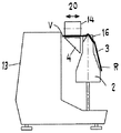
図1は、丁合い綴じ機13の送りもしくは丁合いチェーン2の上に配設されている本発明による装置1を示す。それ自身公知の丁合いチェーン2は、無端の送り機構を構成し、鞍形の領域18を備え、この領域の上を、印刷製品3が馬乗りで送られる。この場合、印刷製品3は、それぞれ横に突き出た翼状のプッシャ16(図2)によって押される。印刷製品3は、特に印刷全紙であり、それぞれ丁合いチェーン2の搬送方向に延在する折り目12を備えている。
FIG. 1 shows a
装置1は、それぞれ少なくとも1つの補助製品5を印刷製品3に取り付けるために使用される。補助製品5は、例えば商品見本、ハガキ又はコンパクトディスク(CD)であり、従って、平坦な製品であることが好ましい。補助製品5の取付けは、印刷製品3の表側V及び/又は裏側Rにおいて行なわれる。従って、選択的に印刷製品には、1つ又は複数の補助製品5が取付け可能である。例えば、4つの補助製品5を印刷製品3に取り付けること、例えば2つの補助製品5を表側Vに、2つの補助製品5を裏側Rに取り付けることもできる。印刷製品3に取り付けられるこれらの補助製品5は、同じであっても、異なっていてもよい。
The
装置1は、図1及び5によれば、引出しローラ7と押付けローラ9の周りに配置されているベルト8又は他の適当な無端の送り機構を有する供給機構14を備えている。引出しローラ7には、図5によれば、複数のグリッパ21又は他の適当な手段が配設されており、これらによって、スタック22からそれぞれ少なくとも1つの補助製品5を引き出すことができる。スタック22は、下部が開放しているマガジン6内に構成され、従って、それぞれ最下部の補助製品5を引き出すことができる。基本的に、マガジン6は、同時に1つより多くの補助製品5を引き出すことができるように形成されていてもよい。スタック22が、マガジン6内で横に移動可能である構成も可能である。加えて、マガジン6内で同時に複数のスタック22が構成されている構成も考えることができる。引き出された補助製品5は、ベルト8から押付けローラ9へと搬送される。搬送方向は、図1では矢印10で示唆されている。押付けローラ9の下で、丁合いチェーン2によって取り付けるべき補助製品5と同調するように印刷製品3が送られる。図2では、補助製品5は、印刷製品3の表側Vに固定される。固定は、例えば、また好ましくは接着によって行なわれる。接着剤は、例えば補助製品5をスタック22から引き出した後この補助製品に塗布すること、例えば吹付けることができる。接着剤を塗布するための適当な手段は、当業者に公知であり、従って、ここでは説明するには及ばない。従って、供給機構14は、スタック22の補助製品5を個別化し、それぞれ印刷製品3に供給する個別化装置でもある。押付けローラ9の領域内での個別化された補助製品5の搬送は、結局、図1において矢印11で示唆されている丁合いチェーン2の搬送方向に移行する。補助製品5が印刷製品3に到達したら、先ず、補助製品5の前縁部5aが印刷製品3に装着され、この前縁部は、印刷製品3と同じ速度で移動する。相応に、供給機構14の速度は調整されている。補助製品5の装着は、当然、丁合いチェーン2もしくは丁合い綴じ機13の周期で行なわれる。
The
図1に従って、補助製品5が表側Vに取り付けられる場合、図2に従って、表側Vは、水平な整向へともたらされる。裏面R並びに折り目12は、元の搬送される位置に留まっている。表側Vを言及した本質的に水平な整向へともたらすために、案内手段4が設けられており、これらの案内手段は、例えば案内板によって構成され、この案内板は、図1によれば、水平な支持面4aを構成する。案内手段4は、表側Vを搬送中に図1に示した本質的に水平な位置へと持ち上げる。印刷製品3が、その折り目12でもって更に鞍形の領域18に当接するように、適当な抑圧ホルダを設けてもよい。
According to FIG. 1, when the
供給機構14は、図2によれば、2重矢印20の方向に水平で丁合いチェーン2の送り方向に対して横に移動することができる。これにより、折り目12に対する補助製品5の間隔を任意に調整することが可能である。加えて、供給機構14の移動が丁合いチェーン2の搬送方向に行なわれることが好ましい。従って、補助製品5が表側Vにもたらされる位置は、任意に選択することができる。
According to FIG. 2, the
図3は、補助製品5が裏側Rに取り付けられる配設を示す。従って、丁合いチェーン2には、図3では、右側に水平な支持面4a’を有する案内手段4’が配設されている。同様に、供給機構14は、鞍形の領域18の右に配設されている。補助製品5の送り及び押付けは、上で説明したように行なわれる。案内手段4及び4’は、取外し可能である。
FIG. 3 shows an arrangement in which the
図4は、両方の案内手段4及び4’が取り付けられている配設を示す。表側Vも裏側Rも、同時に水平に整向されている。供給機構14によって、補助製品5が表側Vに、同時に第2の供給機構14’によって、補助製品5が裏側Rに取り付けられる。供給機構14は、2重矢印20の方向に丁合いチェーン2の搬送方向に対して横に移動可能であり、供給機構14’は、2重矢印20’の方向に移動可能である。丁合いチェーン2の搬送方向に両方の供給機構14及び14’の前又は後に再度2つのこのような供給機構が配設されている構成も考えることができる。この場合、印刷製品3に対して、同時に2つの、後で再度2つの補助製品5を取り付けることができ、従って、全部で4つの補助製品5が取り付けられている。
FIG. 4 shows an arrangement in which both guide means 4 and 4 'are mounted. Both the front side V and the back side R are simultaneously oriented horizontally. The
図5は、再度概略的に、どのようにスタック22の補助製品5がグリッパ21によって個別化されて印刷製品3へと搬送されるかを示す。印刷製品3は、図5では、矢印17の方向に右から左に送られる。送り速度は、押付け工程の間は変更されない。従って、ベルト8の速度は、丁合いチェーン2の搬送速度に適合されている。加えて、補助製品5の引出し及び押付けは、丁合いチェーン2の周期で行なわれる。明らかなように、それぞれ2つのプッシャ16の間に印刷製品3が存在し、その際、この印刷製品は、後方のプッシャに当接している。供給機構14は、好ましくは、この供給機構が矢印17の方向にも、並びにこれとは逆の方向にも変位可能であるように支承されている。従って、印刷製品3上の補助製品5の位置は、折り目12の方向にも無段階に調整することができる。基本的に、横方向の調整も考えることができ、従って、この場合、引出しローラ7及び押付けローラ9の軸は、矢印17の方向もしくは折り目12の方向に対して横に延在する。
FIG. 5 again schematically shows how the
図6は、裏側Rのほぼ中心に取り付けられた補助製品5を有する印刷製品3を示す。破線で、横にずらされ、より折り目12のそばに取り付けられている補助製品5’が示唆されている。他の方向にずらされているのは、一点鎖線で示唆されている補助製品5”である。結局、補助製品5の横に延在する他の整向も考えることができる。補助製品5の位置は、2重矢印19の方向にずらされていてもよい。
FIG. 6 shows a printed
1 本発明による装置
2 送りもしくは丁合いチェーン
3 印刷製品
4 案内手段
4a 支持面
5 補助製品
5a 前縁部
6 マガジン
7 引出しローラ
8 ベルト
9 押付けローラ
10 搬送方向(矢印)
11 搬送方向(矢印)
12 折り目
13 丁合い綴じ機
14 供給機構
16 プッシャ
18 鞍形の領域
20 2重矢印
21 グリッパ
22 スタック
V 印刷製品の表側
R 印刷製品の裏側
DESCRIPTION OF
11 Transport direction (arrow)
12
Claims (17)
側面脚部が、案内機構(4,4’)によって、ほぼ水平な位置へと持ち上げられ、送りチェーン(2)の送り方向及び送りチェーン(2)の送り方向に対して横に移動可能な供給機構(14)によって、補助製品(5)が、少なくともほぼ同方向の送り方向及び速度で印刷製品(3)に供給され、供給機構(14)が備える無端の搬送ベルト(8)の引渡し端によって、補助製品(5)が、案内機構(4,4’)の水平な支持面(4a,4a’)上で、圧力下で印刷製品(3)の側面脚部の側面に取り付けられることを特徴とする方法。 An auxiliary product (at least approximately flat) on at least one side surface of the side leg portion on which both sides of the printed product (3) that is placed on the horseback and conveyed on the rotating feed chain (2) hangs downward. 5) In the method for attaching
The side legs are lifted to a substantially horizontal position by the guide mechanism (4, 4 ') and can be moved laterally with respect to the feed direction of the feed chain (2) and the feed direction of the feed chain (2). By means of the mechanism (14), the auxiliary product (5) is fed to the printed product (3) at least in substantially the same feed direction and speed, and by the delivery end of the endless conveyor belt (8) provided in the feed mechanism (14) The auxiliary product (5) is mounted on the side of the side leg of the printed product (3) under pressure on the horizontal support surface (4a, 4a ′) of the guide mechanism (4, 4 ′). And how to.
送りチェーン(2)に沿って、印刷製品(3)の少なくとも一方の側面脚部の持上げを行なう案内機構(4,4’)と、この案内機構に対して、水平の位置へと持ち上げられた側面脚部の向かい合って位置する側に付設される補助製品(5)を供給するための送りチェーン(2)の送り方向及び送りチェーン(2)の送り方向に対して横に移動可能な供給機構(14)とが配設されており、この供給機構(14)が、搬送される補助製品(5)の担体として形成された、補助製品(5)をスタック(22)から引き出して側面脚部の側面に供給する無端の搬送ベルト(8)を備え、この搬送ベルト(8)の引渡し端が、バネ力によって得られた圧力下で案内機構(4,4’)の水平な支持面(4a,4a’)に載置されていることを特徴とする装置。 10. A feed chain (2) driven to rotate, comprising a saddle-shaped platform and a pusher (16) for a printed product (3) to be conveyed on a horseback. In an apparatus for carrying out the method according to one,
A guide mechanism (4, 4 ') for lifting at least one side leg of the printed product (3) along the feed chain (2), and the guide mechanism is lifted to a horizontal position. Feeding mechanism capable of moving laterally with respect to the feed direction of the feed chain (2) and the feed direction of the feed chain (2) for feeding the auxiliary product (5) attached to the opposite side of the side legs (14) is arranged, and the supply mechanism (14) pulls out the auxiliary product (5) formed as a carrier of the auxiliary product (5) to be conveyed from the stack (22), and the side legs. An endless conveying belt (8) for supplying the side surface of the guide belt (8) is provided, and the delivery end of the conveying belt (8) is supported by a horizontal support surface (4a) of the guide mechanism (4, 4 ') under pressure obtained by a spring force. , instrumentation, characterized in that mounted on the 4a ') .
Applications Claiming Priority (2)
| Application Number | Priority Date | Filing Date | Title |
|---|---|---|---|
| EP04405251A EP1588861B1 (en) | 2004-04-23 | 2004-04-23 | Process and device for applying an at least nearly flat supplemental product on a lateral surface of a signature |
| EP04405251.2 | 2004-04-23 |
Publications (3)
| Publication Number | Publication Date |
|---|---|
| JP2005306609A JP2005306609A (en) | 2005-11-04 |
| JP2005306609A5 JP2005306609A5 (en) | 2008-04-03 |
| JP5054286B2 true JP5054286B2 (en) | 2012-10-24 |
Family
ID=34932072
Family Applications (1)
| Application Number | Title | Priority Date | Filing Date |
|---|---|---|---|
| JP2005077018A Expired - Fee Related JP5054286B2 (en) | 2004-04-23 | 2005-03-17 | Method and apparatus for attaching at least a substantially flat auxiliary product to the side of a printed product |
Country Status (3)
| Country | Link |
|---|---|
| US (2) | US7438107B2 (en) |
| EP (1) | EP1588861B1 (en) |
| JP (1) | JP5054286B2 (en) |
Families Citing this family (1)
| Publication number | Priority date | Publication date | Assignee | Title |
|---|---|---|---|---|
| CN101489801B (en) * | 2006-08-21 | 2012-07-04 | 高斯国际美洲公司 | Mobile feeder system |
Family Cites Families (11)
| Publication number | Priority date | Publication date | Assignee | Title |
|---|---|---|---|---|
| US3658318A (en) * | 1970-07-10 | 1972-04-25 | Mccall Corp | Method and apparatus for adding loose inserts to magazines |
| DE2135303A1 (en) * | 1971-07-15 | 1973-08-09 | Girardet Graphische Betriebe U | DEVICE FOR GLUING SAMPLES IN MAGAZINES, NEWSPAPERS OR. DGL. |
| US4242168A (en) * | 1979-04-27 | 1980-12-30 | A-T-O Inc. | Labeling machine |
| WO1983004221A1 (en) * | 1982-06-04 | 1983-12-08 | Flensburg Carl G A | Apparatus for pasting inserts into publications |
| US4493482A (en) * | 1983-09-27 | 1985-01-15 | Alden Press, Inc. | Motion stabilizing and aligning apparatus for moving folded signatures through an ink jet printer |
| US4917367A (en) * | 1988-08-29 | 1990-04-17 | Sterne Harold E | On-line tipping apparatus for a signature inserting machine |
| US5067699A (en) * | 1990-02-07 | 1991-11-26 | Am International Incorporated | Sheet material handling apparatus with inserter assembly |
| JP4051426B2 (en) * | 1997-08-20 | 2008-02-27 | 大日本印刷株式会社 | Attachment pasting device |
| DE50108929D1 (en) | 2000-05-16 | 2006-04-20 | Heidelberger Druckmasch Ag | Apparatus for collecting flat printed products |
| DK1275607T3 (en) | 2001-07-10 | 2004-11-08 | Ferag Ag | Device for placing supplementary products on printing products |
| DE50308405D1 (en) * | 2003-04-04 | 2007-11-29 | Mueller Martini Holding Ag | Method for producing a printed product consisting of at least one printed product stapled to the outer seam edge inwardly |
-
2004
- 2004-04-23 EP EP04405251A patent/EP1588861B1/en not_active Expired - Lifetime
-
2005
- 2005-03-17 JP JP2005077018A patent/JP5054286B2/en not_active Expired - Fee Related
- 2005-04-21 US US11/111,068 patent/US7438107B2/en not_active Expired - Fee Related
-
2008
- 2008-09-11 US US12/283,316 patent/US8162019B2/en not_active Expired - Fee Related
Also Published As
| Publication number | Publication date |
|---|---|
| US20050241753A1 (en) | 2005-11-03 |
| EP1588861B1 (en) | 2012-02-29 |
| US7438107B2 (en) | 2008-10-21 |
| US8162019B2 (en) | 2012-04-24 |
| US20090038733A1 (en) | 2009-02-12 |
| EP1588861A1 (en) | 2005-10-26 |
| JP2005306609A (en) | 2005-11-04 |
Similar Documents
| Publication | Publication Date | Title |
|---|---|---|
| JP5449304B2 (en) | Bundling system and method for bundling stacked products | |
| US9987834B2 (en) | Apparatus and method for removing pressure adhesive labels from backing and affixing to target substrate | |
| JPH04247995A (en) | Device and method for individual printing on fold section while fold section is transferred to bookbinding line conveyor | |
| JP5395177B2 (en) | Apparatus for inserting individual articles into envelopes and related methods | |
| JP2010111121A (en) | Device for thread-stitching of folded print product | |
| JP5054286B2 (en) | Method and apparatus for attaching at least a substantially flat auxiliary product to the side of a printed product | |
| JP2009298595A (en) | Device and method for removing flat print product from pile and transferring the print product to transport device under operation | |
| GB2109347A (en) | Controlling flow of overlapped documents and glueing documents to a carrier sheet | |
| JPH02245384A (en) | Apparatus and method for individually printing signatures during their transfer onto bookbinding line conveyor | |
| US10589947B2 (en) | Apparatus for franking flat items of mail transported individually or from a supplied stack, such as envelopes, mailers, cards, printed products, sleeves, labels or the like, on a processing line | |
| JPH08217283A (en) | Separately conveying device for set of document | |
| JP2007031154A (en) | Method and device for aligning/fixing printed paper | |
| JP6778688B2 (en) | Packaging groups and methods for wrapping products, especially edited products, in storage bands | |
| JP2842799B2 (en) | Bonding machine | |
| JP4135923B2 (en) | Paper machine | |
| US11420840B2 (en) | Method for franking packages individually supplied from a stack by a franking machine | |
| JPH028913Y2 (en) | ||
| JP3328706B2 (en) | Origami printed matter supply device | |
| JPH07157119A (en) | Section feeding device | |
| JP4223100B2 (en) | Cover supply device | |
| JP3403996B2 (en) | Paper transport device | |
| JPH0324522Y2 (en) | ||
| JPH04339711A (en) | Paper support feeding device for sectioning/binding device | |
| JPH0266031A (en) | Bundled sheet feeder | |
| JP2003300614A (en) | Device and method of moving books |
Legal Events
| Date | Code | Title | Description |
|---|---|---|---|
| A521 | Request for written amendment filed |
Free format text: JAPANESE INTERMEDIATE CODE: A523 Effective date: 20080214 |
|
| A621 | Written request for application examination |
Free format text: JAPANESE INTERMEDIATE CODE: A621 Effective date: 20080214 |
|
| RD04 | Notification of resignation of power of attorney |
Free format text: JAPANESE INTERMEDIATE CODE: A7424 Effective date: 20100527 |
|
| A977 | Report on retrieval |
Free format text: JAPANESE INTERMEDIATE CODE: A971007 Effective date: 20101020 |
|
| A131 | Notification of reasons for refusal |
Free format text: JAPANESE INTERMEDIATE CODE: A131 Effective date: 20101221 |
|
| A601 | Written request for extension of time |
Free format text: JAPANESE INTERMEDIATE CODE: A601 Effective date: 20110318 |
|
| A602 | Written permission of extension of time |
Free format text: JAPANESE INTERMEDIATE CODE: A602 Effective date: 20110330 |
|
| A521 | Request for written amendment filed |
Free format text: JAPANESE INTERMEDIATE CODE: A523 Effective date: 20110614 |
|
| A02 | Decision of refusal |
Free format text: JAPANESE INTERMEDIATE CODE: A02 Effective date: 20111122 |
|
| A521 | Request for written amendment filed |
Free format text: JAPANESE INTERMEDIATE CODE: A523 Effective date: 20120316 |
|
| A911 | Transfer to examiner for re-examination before appeal (zenchi) |
Free format text: JAPANESE INTERMEDIATE CODE: A911 Effective date: 20120326 |
|
| TRDD | Decision of grant or rejection written | ||
| A01 | Written decision to grant a patent or to grant a registration (utility model) |
Free format text: JAPANESE INTERMEDIATE CODE: A01 Effective date: 20120724 |
|
| A01 | Written decision to grant a patent or to grant a registration (utility model) |
Free format text: JAPANESE INTERMEDIATE CODE: A01 |
|
| A61 | First payment of annual fees (during grant procedure) |
Free format text: JAPANESE INTERMEDIATE CODE: A61 Effective date: 20120727 |
|
| R150 | Certificate of patent or registration of utility model |
Free format text: JAPANESE INTERMEDIATE CODE: R150 |
|
| FPAY | Renewal fee payment (event date is renewal date of database) |
Free format text: PAYMENT UNTIL: 20150803 Year of fee payment: 3 |
|
| R250 | Receipt of annual fees |
Free format text: JAPANESE INTERMEDIATE CODE: R250 |
|
| LAPS | Cancellation because of no payment of annual fees |