JP5048829B2 - Driving support system - Google Patents
Driving support system Download PDFInfo
- Publication number
- JP5048829B2 JP5048829B2 JP2010505706A JP2010505706A JP5048829B2 JP 5048829 B2 JP5048829 B2 JP 5048829B2 JP 2010505706 A JP2010505706 A JP 2010505706A JP 2010505706 A JP2010505706 A JP 2010505706A JP 5048829 B2 JP5048829 B2 JP 5048829B2
- Authority
- JP
- Japan
- Prior art keywords
- uhf
- vehicle
- frequency
- roadside
- dsrc
- Prior art date
- Legal status (The legal status is an assumption and is not a legal conclusion. Google has not performed a legal analysis and makes no representation as to the accuracy of the status listed.)
- Active
Links
Images


Classifications
-
- H—ELECTRICITY
- H04—ELECTRIC COMMUNICATION TECHNIQUE
- H04W—WIRELESS COMMUNICATION NETWORKS
- H04W16/00—Network planning, e.g. coverage or traffic planning tools; Network deployment, e.g. resource partitioning or cells structures
- H04W16/24—Cell structures
- H04W16/30—Special cell shapes, e.g. doughnuts or ring cells
-
- G—PHYSICS
- G08—SIGNALLING
- G08G—TRAFFIC CONTROL SYSTEMS
- G08G1/00—Traffic control systems for road vehicles
- G08G1/09—Arrangements for giving variable traffic instructions
- G08G1/0962—Arrangements for giving variable traffic instructions having an indicator mounted inside the vehicle, e.g. giving voice messages
- G08G1/0967—Systems involving transmission of highway information, e.g. weather, speed limits
- G08G1/096766—Systems involving transmission of highway information, e.g. weather, speed limits where the system is characterised by the origin of the information transmission
- G08G1/096783—Systems involving transmission of highway information, e.g. weather, speed limits where the system is characterised by the origin of the information transmission where the origin of the information is a roadside individual element
-
- H—ELECTRICITY
- H04—ELECTRIC COMMUNICATION TECHNIQUE
- H04W—WIRELESS COMMUNICATION NETWORKS
- H04W4/00—Services specially adapted for wireless communication networks; Facilities therefor
- H04W4/02—Services making use of location information
-
- H—ELECTRICITY
- H04—ELECTRIC COMMUNICATION TECHNIQUE
- H04W—WIRELESS COMMUNICATION NETWORKS
- H04W4/00—Services specially adapted for wireless communication networks; Facilities therefor
- H04W4/02—Services making use of location information
- H04W4/029—Location-based management or tracking services
Landscapes
- Engineering & Computer Science (AREA)
- Computer Networks & Wireless Communication (AREA)
- Signal Processing (AREA)
- Traffic Control Systems (AREA)
- Mobile Radio Communication Systems (AREA)
Description
本発明は、例えば、UHF(Ultra−High Frequency)波により交通情報を提供して安全運転を支援する運転支援システムに関するものである。 The present invention relates to a driving support system that supports traffic driving by providing traffic information using, for example, UHF (Ultra-High Frequency) waves.
現在、交差点及び交差点進入路でドライバ−の不注意により起きる交通事故を防止することを目的として安全運転支援システム(以下、DSSS[Driving Safety Support Systems]という)の検証実験が行われている。
例えば、DSSSは、ドライバーに対して周辺の交通状況を視覚や聴覚により認識可能な情報(例えば、注意を促す画像の表示や音声メッセージの出力)で提供し、危険要因に対する注意を促し、ゆとりを持った運転を支援するシステムである。Currently, a verification experiment of a safe driving support system (hereinafter referred to as DSSS [Driving Safety Support Systems]) is being conducted for the purpose of preventing traffic accidents caused by driver's carelessness at intersections and intersection approach roads.
For example, DSSS provides drivers with information that allows them to recognize the surrounding traffic situation visually or auditorily (for example, displaying an image that calls attention or outputting a voice message) It is a system that supports driving
DSSSシステムは、光信号を発信する発信器(以下、光ビーコン装置という)、5.8GHz帯の電波を発信する発信器(以下、DSRCビーコン装置という)、路側制御装置(情報中継・判定装置)を有する路側側の装置(以下、情報中継・判定装置という)と、光ビーコン装置およびDSRCビーコン装置との間でデータをやりとりする車載器とを構成要素にしている。
さらに、DSSSシステムは、交差点に進入する四輪車両や自動二輪車両の交差点までの距離や走行速度を検出する車両検知センサや交差点の横断歩道を歩行している歩行者や横断歩道上の自転車を検出する歩行者検知センサでそれぞれ検知した位置情報や速度情報や車両台数及び人数を検知し出力する機能を有するセンサ(以下、検知センサという)と交差点の交通流を制御する信号制御機(以下、信号制御機という)を路側側の装置として備える。路側制御装置は、信号制御機からの交差点信号情報と検知センサからの検知情報とを収集し、光ビーコン装置やDSRCビーコン装置にそれらの情報を伝達する。The DSSS system includes a transmitter that transmits an optical signal (hereinafter referred to as an optical beacon device), a transmitter that transmits a radio wave of 5.8 GHz band (hereinafter referred to as a DSRC beacon device), and a roadside control device (information relay / determination device). And a vehicle-mounted device that exchanges data between an optical beacon device and a DSRC beacon device.
In addition, the DSSS system is a vehicle detection sensor that detects the distance and travel speed of four-wheeled vehicles and motorcycles that enter the intersection, and pedestrians walking on the intersection and bicycles on the pedestrian crossing. A sensor (hereinafter referred to as a detection sensor) having a function of detecting and outputting position information, speed information, the number of vehicles, and the number of persons detected by the pedestrian detection sensor to be detected and a signal controller for controlling traffic flow at the intersection (hereinafter referred to as a detection sensor) A signal controller) as a roadside device. The roadside control device collects the intersection signal information from the signal controller and the detection information from the detection sensor, and transmits the information to the optical beacon device and the DSRC beacon device.
光ビーコン装置は、交差点手前に設置され、車両に対してその車両が走行している車線位置やDSSSサービスを提供していることを伝達したり、交差点の大きさや脇道の有無などの地理的情報のような静的な情報(以下、固定情報という)を光ビーコン受信車載器を介して車両に提供したりする。
路側制御装置(情報中継・判定装置)は、検知センサで検出した交差点に進入してくる対向車両の位置や対向車両の速度情報や交差点内の横断歩道上の歩行者や自転車などの存在情報と、信号制御機から出力される信号機の灯色情報を収集することにより、リアルタイムに変化する交通(交差点)情報を作成しDSRCビーコン装置に伝送する。
DSRCビーコン装置は、交差点付近に設置され、路側制御装置により作成されたリアルタイムに変化する交通情報を車両に提供する。The optical beacon device is installed in front of the intersection and communicates to the vehicle that the vehicle is driving and the location of the lane and the DSSS service is provided, and geographical information such as the size of the intersection and the presence of side streets Such static information (hereinafter referred to as fixed information) is provided to the vehicle via the optical beacon receiving vehicle-mounted device.
The roadside control device (information relay / determination device) detects the position of the oncoming vehicle entering the intersection detected by the detection sensor, the speed information of the oncoming vehicle, presence information such as pedestrians and bicycles on the pedestrian crossing in the intersection, and so on. By collecting the signal color information output from the signal controller, traffic (intersection) information that changes in real time is created and transmitted to the DSRC beacon device.
The DSRC beacon device is installed in the vicinity of an intersection, and provides the vehicle with traffic information that changes in real time created by the roadside control device.
上記のDSSSにより、例えば、交差点における右折事故防止サービスや左折巻き込み事故防止システムの評価検証が行われている。
上記のDSSSには、交差点において、トラックやバス等の大型車両の影部分(以下、シャドーイングという)では、車載器がDSRCビーコン装置からの情報を受信できなくなるという課題がある。
また、上記のDSSSによる安全運転支援サービス(例えば、追突防止サービス)は交差点付近でしか提供することができないが、交差点から離れた位置(100m以遠)においても車載器を搭載した車両に対して提供されることが望まれている。The above-mentioned DSSS has a problem that the vehicle-mounted device cannot receive information from the DSRC beacon device at the intersection in a shadow portion of a large vehicle such as a truck or a bus (hereinafter referred to as shadowing).
In addition, the DSSS safe driving support service (for example, rear-end collision prevention service) can only be provided near the intersection, but it is also provided for vehicles equipped with onboard equipment even at positions far from the intersection (100 meters or more). It is hoped that will be done.
本発明は、例えば、大型車両の影部分に位置する車両の車載器にも交通情報を受信させられるようにすることを目的とする。
また例えば、本発明は、交差点から離れた地点を走行している車両の車載器にも交通情報を受信させられるようにすることを目的とする。For example, an object of the present invention is to allow a vehicle-mounted device of a vehicle located in a shadow portion of a large vehicle to receive traffic information.
In addition, for example, an object of the present invention is to allow a vehicle-mounted device of a vehicle traveling at a point away from an intersection to receive traffic information.
本発明の運転支援システムは、車両に搭載される車載器に対してUHF(Ultra−High Frequency)波を用いて交通情報を提供するUHF路側機を有する運転支援システムであり、前記UHF路側機は、内容の異なる複数の交通情報それぞれを周波数の異なるUHF波に設定すると共に各UHF波を異なる送信出力で発信する。 The driving support system of the present invention is a driving support system having a UHF roadside machine that provides traffic information using UHF (Ultra-High Frequency) waves to an in-vehicle device mounted on a vehicle, and the UHF roadside machine is A plurality of pieces of traffic information having different contents are set to UHF waves having different frequencies, and each UHF wave is transmitted with a different transmission output.
前記UHF路側機は、前記各UHF波を時分割により発信する。 The UHF roadside unit transmits each UHF wave by time division.
前記UHF路側機は、前記各UHF波として周波数の異なる3つのUHF波を、送信出力の小さい順に6対3対1の時間割合で発信する。 The UHF roadside unit transmits three UHF waves having different frequencies as the UHF waves at a time ratio of 6 to 3 to 1 in ascending order of transmission output.
前記運転支援システムは、前記UHF路側機を複数有し、
複数の前記UHF路側機は、前記各UHF波のうち最も小さい送信出力で発信されるUHF波が到達するゾーンが互いに重ならず、且つ、前記各UHF波のうち最も大きい送信出力で発信されるUHF波が到達するゾーンが互いに重なる間隔で配置される。The driving support system includes a plurality of the UHF roadside units,
The plurality of UHF roadside units are transmitted with the highest transmission output among the UHF waves, and zones where the UHF waves transmitted with the smallest transmission output among the UHF waves reach each other do not overlap each other. The zones where the UHF waves reach are arranged at intervals overlapping each other.
隣りに配置された前記UHF路側機同士は、前記各UHF波のうち最も大きい送信出力で発信されるUHF波の周波数が互いに異なる。 The UHF roadside devices arranged next to each other have different frequencies of UHF waves transmitted with the largest transmission output among the UHF waves.
前記運転支援システムは、第1〜第4のUHF路側機を有し、
前記第1〜第4のUHF路側機はそれぞれ、最も小さい送信出力で発信するUHF波に第1の周波数を用い、2番目に小さい送信出力で発信するUHF波に第2の周波数を用い、
第1のUHF路側機は、最も大きい送信出力で発信するUHF波の周波数に第3の周波数を用い、
第2のUHF路側機は、最も大きい送信出力で発信するUHF波の周波数に第4の周波数を用い、
第3のUHF路側機は、最も大きい送信出力で発信するUHF波の周波数に第5の周波数を用い、
第4のUHF路側機は、最も大きい送信出力で発信するUHF波の周波数に第6の周波数を用いる。The driving support system has first to fourth UHF roadside units,
Each of the first to fourth UHF roadside units uses a first frequency for a UHF wave transmitted with the smallest transmission output, and uses a second frequency for a UHF wave transmitted with the second smallest transmission output,
The first UHF roadside machine uses the third frequency for the frequency of the UHF wave transmitted with the largest transmission output,
The second UHF roadside unit uses the fourth frequency for the frequency of the UHF wave transmitted with the largest transmission output,
The third UHF roadside machine uses the fifth frequency as the frequency of the UHF wave transmitted with the largest transmission output,
The fourth UHF roadside machine uses the sixth frequency as the frequency of the UHF wave transmitted with the largest transmission output.
前記UHF路側機は、UHFの周波数帯に含まれる特定の約10.0MHz帯内の互いに重ならない6つの周波数帯を用いて、前記各UHF波を互いに異なる周波数帯で発信する。 The UHF roadside unit transmits the UHF waves in different frequency bands using six frequency bands that do not overlap each other within a specific approximately 10.0 MHz band included in the UHF frequency band.
前記6つの周波数帯は、それぞれの帯域幅が約1.5MHzであり、互いの帯域の間隔が約0.2MHz幅である。 Each of the six frequency bands has a bandwidth of about 1.5 MHz, and an interval between the bands is about 0.2 MHz.
前記6つの周波数帯それぞれの中心周波数はおよそ、715.75MHz、717.45MHz、719.15MHz、720.85MHz、722.55MHzおよび724.25MHzである。 The center frequencies of each of the six frequency bands are approximately 715.75 MHz, 717.45 MHz, 719.15 MHz, 720.85 MHz, 722.55 MHz, and 724.25 MHz.
前記UHF路側機は、前記UHF路側機からの距離が異なる複数のゾーンそれぞれに対応して予め定められたUHF波の周波数を示す情報を含めてUHF波を発信し、
車両に搭載される車載器は、前記UHF路側機から発信されたUHF波と前記車両に搭載されたGPSによる自車位置の測位結果とに基づいて受信周波数を車両が位置するゾーンに対応するUHF波の周波数に変更し、前記UHF路側機から発信される前記各UHF波のうち車両が位置するゾーンに対応するUHF波を受信する。The UHF roadside machine transmits a UHF wave including information indicating a predetermined frequency of the UHF wave corresponding to each of a plurality of zones having different distances from the UHF roadside machine,
The vehicle-mounted device mounted on the vehicle is a UHF corresponding to the zone where the vehicle is located based on the UHF wave transmitted from the UHF roadside unit and the positioning result of the vehicle position by the GPS mounted on the vehicle. The frequency is changed to a wave frequency, and the UHF wave corresponding to the zone where the vehicle is located is received among the UHF waves transmitted from the UHF roadside machine.
前記UHF路側機は、道路に位置する地物の情報を示す道路情報を含めてUHF波を発信し、
車両に搭載される車載器は、前記UHF路側機から発信されたUHF波に含まれる道路情報に基づいて車両の走行位置を特定する。The UHF roadside machine transmits UHF waves including road information indicating information of features located on the road,
The vehicle-mounted device mounted on the vehicle specifies the traveling position of the vehicle based on road information included in the UHF wave transmitted from the UHF roadside machine.
車両に搭載される車載器は、警告情報が入力機器から入力され、前記UHF路側機から受信するUHF波と同じ周波数を用いて警告情報を発信し、
前記UHF路側機は、車載器から発信された警告情報を受信し、受信した警告情報を前記各UHF波それぞれに含めて発信する。The vehicle-mounted device mounted on the vehicle transmits the warning information using the same frequency as the UHF wave received from the UHF roadside device when the warning information is input from the input device,
The UHF roadside device receives the warning information transmitted from the vehicle-mounted device, and transmits the received warning information including each of the UHF waves.
車両に搭載される車載器は、警告情報が入力機器から入力され、前記UHF路側機に使用されていないUHF波の周波数を用いて警告情報を発信し、
前記UHF路側機は、車載器から発信された警告情報を受信し、受信した警告情報を前記各UHF波それぞれに含めて発信する。The vehicle-mounted device mounted on the vehicle transmits the warning information using the frequency of the UHF wave that is not used in the UHF roadside device, and the warning information is input from the input device.
The UHF roadside device receives the warning information transmitted from the vehicle-mounted device, and transmits the received warning information including each of the UHF waves.
前記運転支援システムは、さらに、
車両に搭載される車載器にSHF(Super High Frequency)波を用いて交通情報を提供するDSRC(Dedicated Short Range Communication)路側機が、十字路の交差点に2機配置され、
十字路の交差点に配置された2機のDSRC路側機は、交差点内に向けて互いに交差する対角方向にSHF波を発信する。The driving support system further includes:
Two DSRC (Dedicated Short Range Communication) roadside devices that provide traffic information using SHF (Super High Frequency) waves are mounted on the vehicle-mounted device mounted on the vehicle at the intersection of the crossroads.
The two DSRC roadside devices arranged at the intersection of the crossroads transmit SHF waves in a diagonal direction intersecting each other toward the intersection.
前記2機のDSRC路側機うち、一方のDSRC路側機は、主道路から従道路に右折する車両が交差点に進入したときに当該車両と対向する方向からSHF波を発信する。 Of the two DSRC roadside aircraft, one DSRC roadside aircraft transmits an SHF wave from the direction facing the vehicle when a vehicle turning right from the main road to the secondary road enters the intersection.
前記運転支援システムは、さらに、
車両に搭載される車載器にSHF(Super High Frequency)波を用いて交通情報を提供するDSRC(Dedicated Short Range Communication)路側機が、十字路の交差点に2機配置され、
十字路の交差点に配置された2機のDSRC路側機は、前記車両が交差点に流入する方路に向けてSHF波を発信する。The driving support system further includes:
Two DSRC (Dedicated Short Range Communication) roadside devices that provide traffic information using SHF (Super High Frequency) waves are mounted on the vehicle-mounted device mounted on the vehicle at the intersection of the crossroads.
The two DSRC roadside devices arranged at the intersection of the crossroads transmit SHF waves toward the route where the vehicle flows into the intersection.
前記2機のDSRC路側機はそれぞれ、主道路から従道路に左折する車両が交差点に進
入したときに当該車両と対向する方向からSHF波を発信する。Each of the two DSRC roadside units transmits an SHF wave from a direction facing the vehicle when a vehicle turning left from the main road to the subway enters the intersection.
本発明によれば、例えば、UHF波が有する電波伝搬特性の回折波特性により、大型車両の影部分に位置する車両の車載器にも交通情報を提供することができる。
また例えば、本発明によれば、UHF波が有する伝搬損失特性により、交差点から離れた地点を走行している車両の車載器にも交通情報を受信させることができる。According to the present invention, for example, traffic information can also be provided to an on-vehicle device of a vehicle located in a shadow portion of a large vehicle by the diffracted wave characteristic of the radio wave propagation characteristic of the UHF wave.
Further, for example, according to the present invention, the traffic information can be received also by the vehicle-mounted device of the vehicle traveling at a point away from the intersection due to the propagation loss characteristic of the UHF wave.
実施の形態1.
実施の形態1では、光ビーコンとDSRCビーコンとUHFビーコンとの3通信メディアを用いる安全運転支援システム100について説明する。
In
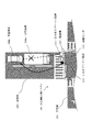
図1は、実施の形態1における安全運転支援システム100の構成を示す図である。
実施の形態1における安全運転支援システム100の構成について、図1に基づいて以下に説明する。
安全運転支援システム100は、DSSSやITS(Intelligent Transport Systems)ともいう。FIG. 1 is a diagram illustrating a configuration of a safe
The configuration of the safe
The safe
安全運転支援システム100は、路側機110、光路側機120、路側制御装置130、信号制御機195などを有し、交差点193および交差点193から離れた地点を走行する車両199の車載器に交通情報を提供する。
路側機110、光路側機120、路側制御装置130、信号制御機195および車載器は、CPU(Central Processing Unit)(中央処理装置、演算装置、マイクロプロセッサ、マイクロコンピュータともいう)を備え、CPUを用いて各処理を実行する。また、路側機110、光路側機120、路側制御装置130、信号制御機195および車載器は、記憶機器(メモリともいう)を備え、記憶機器を用いて各情報を記憶する。RAM(Random Access Memory)や磁気ディスク装置は記憶機器の一例である。
また、路側機110、光路側機120、路側制御装置130および信号制御機195は通信ケーブルで接続されており、通信ケーブルを介して互いに通信する。The safe
The roadside device 110, the optical roadside device 120, the roadside control device 130, the signal controller 195, and the vehicle-mounted device include a CPU (Central Processing Unit) (also referred to as a central processing unit, an arithmetic device, a microprocessor, and a microcomputer). To execute each process. Further, the roadside device 110, the optical roadside device 120, the roadside control device 130, the signal controller 195, and the vehicle-mounted device include a storage device (also referred to as a memory) and store each piece of information using the storage device. A RAM (Random Access Memory) and a magnetic disk device are examples of storage devices.
Further, the roadside device 110, the optical roadside device 120, the roadside control device 130, and the signal controller 195 are connected by a communication cable and communicate with each other via the communication cable.
信号制御機195は、交差点193の各信号機194と通信ケーブルで接続され、通信ケーブルを介して各信号機194の点灯色や点灯時間などを所定の制御情報に基づいて制御する。信号制御機195は、各信号機194に対する制御情報を路側制御装置130に送信する。信号機194の制御情報は予め記憶機器に記憶され、または、信号制御機195の上位装置である交通管制センタから送信される。 The signal controller 195 is connected to each signal device 194 at the intersection 193 via a communication cable, and controls the lighting color and lighting time of each signal device 194 via the communication cable based on predetermined control information. The signal controller 195 transmits control information for each signal device 194 to the roadside control device 130. The control information of the traffic light 194 is stored in a storage device in advance, or is transmitted from a traffic control center that is a higher-level device of the traffic signal controller 195.
光路側機120は、交差点193の手前に設置され、車線(レーン)毎に光ビーコン装
置121を有し、各光ビーコン装置121の下方を通行する車両199の車載器に向けて光ビーコン(光波)信号を発信する。光路側機120は、各光ビーコン装置121から発信する光ビーコン信号に、光ビーコン装置121の座標値、車線情報(直進車線、左折車線、右折車線など)、進入先の交差点においてDSSSサービスを提供中であることの情報、交差点までの距離、交差点の大きさ、脇道の有無などの静的な交通情報を設定する。なお、静的な交通情報は予め記憶機器に記憶されている。
各車両199の車載器は、走行している車線の上方に設置されている光ビーコン装置121から交通情報が設定された光ビーコン信号を受信し、受信した光ビーコン信号から交通情報を取得する。また、各車両199の車載器は、速度、ウインカーの点灯有無、車種、車載器ID(IDentifier)などの運転情報を光波で光ビーコン装置121に発信する。
光ビーコン装置121は車両199の車載器から運転情報を受信し、光路側機120は光ビーコン装置121により受信された運転情報を路側制御装置130に送信する。
光ビーコン装置121を光路側機120と呼んでもよい。The optical path side device 120 is installed in front of the intersection 193, has an optical beacon device 121 for each lane (lane), and is directed to an on-vehicle device of a vehicle 199 that passes under each optical beacon device 121. ) Send a signal. The optical path unit 120 provides the DSSS service to the optical beacon signal transmitted from each optical beacon device 121 at the coordinate value of the optical beacon device 121, lane information (straight ahead lane, left turn lane, right turn lane, etc.) Static traffic information such as information about being inside, the distance to the intersection, the size of the intersection, and the presence or absence of a side road is set. Note that static traffic information is stored in advance in a storage device.
The vehicle-mounted device of each vehicle 199 receives the optical beacon signal in which the traffic information is set from the optical beacon device 121 installed above the traveling lane, and acquires the traffic information from the received optical beacon signal. Moreover, the vehicle-mounted device of each vehicle 199 transmits driving information such as speed, turn-on / off of the blinker, vehicle type, vehicle-mounted device ID (IDentifier) to the optical beacon device 121 by light waves.
The optical beacon device 121 receives driving information from the vehicle-mounted device of the vehicle 199, and the optical roadside device 120 transmits the driving information received by the optical beacon device 121 to the roadside control device 130.
The optical beacon device 121 may be called the optical path side device 120.
路側制御装置130は、信号制御機195から受信した信号機194の制御情報、光路側機120から受信した走行車両の運転情報、後述する画像センサ113から受信した走行車両の識別情報や交差点内横断歩道上の歩行者や自転車などの識別情報などに基づいて交通情報を生成する。路側制御装置130は、生成した交通情報を各路側機110に送信する。
例えば、路側制御装置130は、信号機194の制御情報に基づいて青信号から赤信号に変わるまでの時間を動的な情報として交通情報に設定する。
また例えば、路側制御装置130は、走行車両の運転情報や走行車両の識別情報に基づいて、各車線の走行車両の有無を動的な情報として交通情報に設定する。
また例えば、路側制御装置130は、交差点の車線情報や脇道の情報などを静的な情報として交通情報に設定する。静的な交通情報は予め記憶機器に記憶されている。
また例えば、路側制御装置130は、後述するUHFビーコン装置112の発信周波数を交通情報に設定する。UHFビーコン装置112の発信周波数は、予め記憶機器に記憶される。または、UHFビーコン装置112の発信周波数は、予め、各UHFビーコン装置112に設定されていてもよい。The roadside control device 130 receives the control information of the traffic light 194 received from the traffic light controller 195, the driving information of the traveling vehicle received from the optical roadside device 120, the identification information of the traveling vehicle received from the image sensor 113 described later, and the crosswalk in the intersection. Traffic information is generated based on the identification information of the above pedestrians and bicycles. The roadside control device 130 transmits the generated traffic information to each roadside device 110.
For example, the roadside control device 130 sets the time from the green signal to the red signal in the traffic information as dynamic information based on the control information of the traffic light 194.
For example, the roadside control device 130 sets the presence or absence of a traveling vehicle in each lane as traffic information based on the driving information of the traveling vehicle and the identification information of the traveling vehicle in the traffic information.
For example, the roadside control device 130 sets intersection lane information, side road information, and the like as traffic information in the traffic information. Static traffic information is stored in a storage device in advance.
Further, for example, the roadside control device 130 sets a transmission frequency of a UHF beacon device 112 described later in the traffic information. The transmission frequency of the UHF beacon device 112 is stored in advance in a storage device. Alternatively, the transmission frequency of the UHF beacon device 112 may be set in advance for each UHF beacon device 112.
路側機110(DSRC路側機、UHF路側機)は、DSRCビーコン装置111、UHFビーコン装置112および画像センサ113を備え、交差点入口に設置されている。
路側機110は、画像センサ113で検出された走行車両の識別情報や交差点内横断歩道上の歩行者や自転車などの識別情報を路側制御装置130に送信する。また、路側機110は、路側制御装置130から送信された交通情報をDSRCビーコン装置111およびUHFビーコン装置112を用いて各車両199の車載器に対して発信する。
DSRCビーコン装置111およびUHFビーコン装置112それぞれを、DSRC路側機、UHF路側機と呼んでもよい。The roadside machine 110 (DSRC roadside machine, UHF roadside machine) includes a DSRC beacon device 111, a UHF beacon device 112, and an image sensor 113, and is installed at an intersection entrance.
The roadside device 110 transmits the identification information of the traveling vehicle detected by the image sensor 113 and the identification information of pedestrians and bicycles on the crosswalk in the intersection to the roadside control device 130. Further, the roadside device 110 transmits the traffic information transmitted from the roadside control device 130 to the vehicle-mounted device of each vehicle 199 using the DSRC beacon device 111 and the UHF beacon device 112.
Each of the DSRC beacon device 111 and the UHF beacon device 112 may be referred to as a DSRC roadside device or a UHF roadside device.
DSRCビーコン装置111は、路側制御装置130で生成された交通情報を5.8GHz帯の電波に設定し、交通情報を設定した電波をDSRCビーコン信号として各車両199の車載器に対して発信する。
DSRCビーコンは、マイクロ波の一例であり、SHF(Super High Frequency)波ともいう。The DSRC beacon device 111 sets the traffic information generated by the roadside control device 130 to a radio wave of 5.8 GHz band, and transmits the radio wave in which the traffic information is set to the vehicle-mounted device of each vehicle 199 as a DSRC beacon signal.
The DSRC beacon is an example of a microwave and is also referred to as a SHF (Super High Frequency) wave.
UHFビーコン装置112は、路側制御装置130で生成された交通情報をUHF波(例えば、700MHz帯)に設定し、交通情報を設定したUHF波をUHFビーコン信号として各車両199の車載器に対して発信する。
UHFビーコンは、電波、マイクロ波の一例である。The UHF beacon device 112 sets the traffic information generated by the roadside control device 130 in a UHF wave (for example, 700 MHz band), and the UHF wave in which the traffic information is set is used as a UHF beacon signal for the vehicle-mounted device of each vehicle 199. send.
A UHF beacon is an example of radio waves and microwaves.
画像センサ113は、進行車線(左車線)を撮像し、撮像した画像を画像処理し、走行車両の有無や走行車両の車種(大型車、普通車、二輪車など)を検出する。また、交差点横断歩道上の情報を収集する場合は、横断歩道を撮像できる位置に画像センサ113を設置することで、横断歩道を歩行中の歩行者や自転車などを撮像し、撮像した画像を画像処理し、歩行者や自転車の有無を検出する。画像処理では、車両を表すパターンを画像から検出するパターンマッチングや、車両不在時の画像との比較により、走行車両の有無や走行車両の車種が検出される。同様に、歩行者や自転車などの有無も検出される。 The image sensor 113 captures a traveling lane (left lane), performs image processing on the captured image, and detects the presence or absence of a traveling vehicle and the type of traveling vehicle (large vehicle, ordinary vehicle, motorcycle, etc.). In addition, when collecting information on an intersection pedestrian crossing, the image sensor 113 is installed at a position where the pedestrian crossing can be imaged. Process and detect the presence or absence of pedestrians and bicycles. In the image processing, the presence or absence of the traveling vehicle and the vehicle type of the traveling vehicle are detected by pattern matching for detecting a pattern representing the vehicle from the image and comparison with an image when the vehicle is absent. Similarly, the presence or absence of a pedestrian or bicycle is also detected.
各車両199の車載器は、光ビーコン装置121から発信された光ビーコン信号、DSRCビーコン装置111から発信されたDSRCビーコン信号、UHFビーコン装置112から発信されたUHFビーコン信号を受信し、受信した各ビーコン信号から交通情報を取得し、取得した交通情報に基づいて各種の安全運転支援処理を実行する。
例えば、車載器は、カーナビゲーションシステム(以下、カーナビという)で使用されている現在地の座標を光ビーコン信号の交通情報に設定されている座標値で更新する。
例えば、車載器は、光ビーコン信号の交通情報に設定されている走行車線の車線情報や交差点までの距離をカーナビのディスプレイ装置(以下、画面という)に表示したり、音声メッセージとして出力したりする。
また例えば、車載器は、光ビーコン信号の交通情報に設定されている交差点193までの距離および車両199内で計測されている走行速度に基づいて交差点193までの進入時間を算出し、進入時間およびDSRCビーコン信号およびUHFビーコン信号の交通情報に設定されている赤信号に変わるまでの時間に基づいて、減速を促す音声メッセージを出力したり、車両199の速度を減速制御したりする。
また例えば、車載器は、車両199の右折時に、DSRCビーコン信号およびUHFビーコン信号の交通情報に設定されている走行車両の情報に基づいて、対向車線に、大型車両に隠れてドライバーから確認しづらい直進車両(例えば、二輪車両)が存在することを音声メッセージの出力やカーナビの画面表示によりドライバーに注意喚起する。これにより、右折車両と直進車両との衝突事故(以下、右直事故という)を減少させることができる。
また例えば、車載器は、車両199の左折時に、DSRCビーコン信号およびUHFビーコン信号の交通情報に設定されている走行車両の情報に基づいて、後方から直進してくる二輪車両が存在することを音声メッセージの出力やカーナビの画面表示によりドライバーに注意喚起する。これにより、左折巻き込み事故を減少させることができる。The vehicle-mounted device of each vehicle 199 receives the optical beacon signal transmitted from the optical beacon device 121, the DSRC beacon signal transmitted from the DSRC beacon device 111, and the UHF beacon signal transmitted from the UHF beacon device 112. Traffic information is acquired from the beacon signal, and various safe driving support processes are executed based on the acquired traffic information.
For example, the vehicle-mounted device updates the coordinates of the current location used in a car navigation system (hereinafter referred to as “car navigation”) with the coordinate values set in the traffic information of the optical beacon signal.
For example, the vehicle-mounted device displays the lane information of the traveling lane set in the traffic information of the optical beacon signal and the distance to the intersection on a display device (hereinafter referred to as a screen) of the car navigation system or outputs it as a voice message. .
Further, for example, the vehicle-mounted device calculates the approach time to the intersection 193 based on the distance to the intersection 193 set in the traffic information of the optical beacon signal and the traveling speed measured in the vehicle 199, and the approach time and Based on the time until the red signal set in the traffic information of the DSRC beacon signal and the UHF beacon signal changes, a voice message prompting deceleration is output, or the speed of the vehicle 199 is controlled to be reduced.
Also, for example, when the vehicle 199 turns right, the vehicle-mounted device is difficult to check from the driver behind the large vehicle on the opposite lane based on the information on the traveling vehicle set in the traffic information of the DSRC beacon signal and the UHF beacon signal. The driver is warned that a straight vehicle (for example, a two-wheeled vehicle) exists by outputting a voice message or displaying a car navigation screen. Thereby, the collision accident (henceforth a right-straight accident) with a right turn vehicle and a straight-ahead vehicle can be reduced.
In addition, for example, when the vehicle 199 makes a left turn, the vehicle-mounted device sounds that there is a two-wheeled vehicle that goes straight from the rear based on the traveling vehicle information set in the traffic information of the DSRC beacon signal and the UHF beacon signal. The driver is alerted by outputting a message or displaying the car navigation screen. Thereby, a left turn entrainment accident can be reduced.
図2は、実施の形態1における安全運転支援システム100のシャドーイング時の交通情報の配信を示す図である。
図2に示すように、路側機110の手前に大型車両199aが存在し、大型車両199aのすぐ後方に普通車両199bが存在する場合、DSRCビーコン装置111から発信されるDSRCビーコン信号は、直進性が比較的強いため大型車両199aにより遮蔽され、普通車両199bに到達しない。
一方、UHFビーコン装置112から発信されるUHFビーコン信号は、回折波特性を有するため普通車両199bに到達する。
つまり、実施の形態1の安全運転支援システム100では、UHFビーコンを用いて交通情報を配信することにより、従来のDSRCビーコンでは配信できない遮蔽された領域(シャドーイング領域)にも交通情報を配信することができる。FIG. 2 is a diagram illustrating distribution of traffic information during shadowing of the safe
As shown in FIG. 2, when a large vehicle 199a is present in front of the roadside unit 110 and a normal vehicle 199b is present immediately behind the large vehicle 199a, the DSRC beacon signal transmitted from the DSRC beacon device 111 is straight ahead. Is relatively strong, it is shielded by the large vehicle 199a and does not reach the ordinary vehicle 199b.
On the other hand, since the UHF beacon signal transmitted from the UHF beacon device 112 has a diffracted wave characteristic, it reaches the ordinary vehicle 199b.
That is, in the safe
図3は、非シャドーイング時におけるDSRCビーコンの電界強度特性(非シャドーイング201)と、シャドーイング時におけるDSRCビーコンの電界強度特性(DSRCビーコン202)と、シャドーイング時におけるUHFビーコンの電界強度特性(UHFビーコン203)とを示す図である。
交差点から約10メートルの地点に大型車両199aが存在する場合について、各地点で計測したDSRCビーコン202およびUHFビーコン203の電界強度について、図3に基づいて以下に説明する。
非シャドーイング201は、大型車両199aが存在しないときに測定したDSRCビーコンの電界強度を示している。FIG. 3 shows a field strength characteristic of a DSRC beacon during non-shadowing (non-shadowing 201), a field strength characteristic of a DSRC beacon during shadowing (DSRC beacon 202), and a field strength characteristic of a UHF beacon during shadowing. It is a figure which shows (UHF beacon 203).
The electric field strength of the
The non-shadowing 201 indicates the electric field strength of the DSRC beacon measured when the large vehicle 199a is not present.
図3に示すように、DSRCビーコン202は、大型車両199aの後方(交差点から10メートル以遠)における電界強度が非常に小さく、大型車両199aの後方に位置する普通車両199bの車載器には受信されない。これは、DSRCビーコン202がUHFビーコン203と比較して強い直進性を有し、大型車両199aにより遮蔽されるためである。
一方、UHFビーコン203は、大型車両199aの後方における電界強度が、多少は弱まるものの、車載器による受信が可能な程度に十分保たれ、大型車両199aの後方に位置する普通車両199bの車載器に受信される。これは、UHFビーコン203がDSRCビーコン202と比較して強い回折波特性を有するためである。As shown in FIG. 3, the
On the other hand, the UHF beacon 203 has a field intensity at the rear of the large vehicle 199a that is somewhat weakened, but is sufficiently maintained to be received by the vehicle-mounted device, and is a vehicle-mounted device for the ordinary vehicle 199b located behind the large vehicle 199a. Received. This is because the UHF beacon 203 has stronger diffracted wave characteristics than the
但し、DSRCビーコンは、UHFビーコン(実施の形態3で約1.5Mbps)と比較して伝送速度が速いため(約4Mbps)、データサイズが大きくUHFビーコンでは配信することが難しい画像や音声を配信することができる。
そこで、実施の形態1の安全運転支援システム100では、UHFビーコンを用いて重要度の高い必要最低限の交通情報をテキストデータで配信し、DSRCビーコンを用いて全ての交通情報をテキストデータ、画像データおよび音声データで配信する。例えば、DSRCビーコンを用いて、画像センサ113で撮像された画像やカーナビ画面に表示させる注意喚起用のアニメーションや車両199内で出力させる警告音声メッセージなどを配信するとよい。However, because the DSRC beacon has a higher transmission speed (about 4 Mbps) compared to the UHF beacon (about 1.5 Mbps in the third embodiment), it delivers images and sounds that are difficult to deliver with UHF beacons. can do.
Therefore, in the safe
つまり、実施の形態1では、UHFビーコンを用いることにより、シャドーイング領域に位置する車両199に対して、ドライバに対する危険度または重要度の高い交通情報を配信することができると共に、DSRCビーコンを用いることにより、非シャドーイング領域に位置する車両199に対してより多くの交通情報を配信することができる。 That is, in the first embodiment, by using the UHF beacon, traffic information with a high degree of risk or importance for the driver can be distributed to the vehicle 199 located in the shadowing area, and the DSRC beacon is used. Thus, more traffic information can be distributed to the vehicle 199 located in the non-shadowing area.
実施の形態1では、以下のような安全運転支援システム100について説明した。
UHFビーコン装置112をDSRCビーコン装置111付近に配置し、DSRCビーコンと同様に、UHFビーコンにより交通情報(交差点情報など)を提供する。
これにより、DSRCビーコンと車載器とがシャドーイングで通信できなくても、UHF電波の回折波特性を利用することで、車載器との通信が可能となり、交通情報を提供することができる。In the first embodiment, the following safe
The UHF beacon device 112 is arranged in the vicinity of the DSRC beacon device 111, and traffic information (intersection information and the like) is provided by the UHF beacon in the same manner as the DSRC beacon.
As a result, even if the DSRC beacon and the vehicle-mounted device cannot communicate with each other by shadowing, communication with the vehicle-mounted device is possible by using the diffracted wave characteristic of the UHF radio wave, and traffic information can be provided.
実施の形態2.
実施の形態2では、実施の形態1で説明した安全運転支援システム100について、DSRCビーコンより遠くまで通信可能なUHFビーコンの長距離通信特性(伝搬損失特性)を利用し、UHFビーコンの通信可能範囲(電波到達範囲)をUHFビーコン装置112からの距離に応じて複数のUHF通信ゾーンに分け、UHFビーコン装置112から各ゾーンに異なる交通情報を配信する形態を説明する。
In the second embodiment, the safe
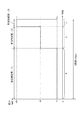
図4は、実施の形態2におけるUHFビーコンによる交通情報の配信ゾーンを示す図である。
実施の形態2では、図4に示すように、UHFビーコンの電波の到達範囲をUHFビーコン装置112から近い近距離ゾーン291、UHFビーコン装置112からの距離が近距離ゾーン291より遠い中距離ゾーン292およびUHFビーコン装置112からの距
離が中距離ゾーン292より遠い遠距離ゾーン293の3つのゾーンに分ける。
例えば、UHFビーコン装置112に対する各ゾーンの最遠距離の比を1:2:4とし、UHFビーコン装置112から半径約100メートルの範囲を近距離ゾーン291、UHFビーコン装置112から半径約200メートルの範囲(近距離ゾーン291を除く)を中距離ゾーン292、UHFビーコン装置112から半径約400メートルの範囲(近距離ゾーン291および中距離ゾーン292を除く)を遠距離ゾーン293とする。
近距離ゾーン291、中距離ゾーン292および遠距離ゾーン293はUHFビーコン装置112を中心とする同心円状の範囲である。FIG. 4 is a diagram showing a distribution zone of traffic information by the UHF beacon in the second embodiment.
In the second embodiment, as shown in FIG. 4, the reach range of the radio wave of the UHF beacon is a short distance zone 291 near the UHF beacon device 112, and the middle distance zone 292 where the distance from the UHF beacon device 112 is far from the short distance zone 291. And the distance from the UHF beacon device 112 is divided into three zones, a long-distance zone 293 farther than the medium-distance zone 292.
For example, the ratio of the farthest distance of each zone to the UHF beacon device 112 is 1: 2: 4, and the range of the radius of about 100 meters from the UHF beacon device 112 is a short distance zone 291 and the radius of the UHF beacon device 112 is about 200 meters. A range (excluding the short-distance zone 291) is defined as a medium-distance zone 292, and a range having a radius of about 400 meters from the UHF beacon device 112 (excluding the short-distance zone 291 and the medium-distance zone 292) is defined as a long-distance zone 293.
The short-distance zone 291, the middle-distance zone 292, and the long-distance zone 293 are concentric ranges centered on the UHF beacon device 112.
そして、各ゾーンには異なる時間帯に異なる周波数で異なる交通情報が配信される。つまり、実施の形態2では、時分割・周波数分割により異なる交通情報を異なるゾーンに配信する。
例えば、近距離ゾーン291には第1の時間帯に周波数f1で近距離向けの交通情報が配信され、中距離ゾーン292には第2の時間帯に周波数f2で中距離向けの交通情報が配信され、遠距離ゾーン293には第3の時間帯に周波数f3で遠距離向けの交通情報が配信される。
例えば、遠距離ゾーン293に配信される遠距離向けの交通情報は、DSSSのシステム情報(または、サービス情報)や遠距離ゾーン293の道路情報を示す。DSSSのシステム情報とは、交通情報の提供の有無(サービス提供の有無)、各ゾーン用の運用周波数、各ゾーンの範囲などのことである。各ゾーンの範囲は、交差点193またはUHFビーコン装置112からの距離、各ゾーンの半径、絶対座標などで示される。DSSSのシステム情報および遠距離ゾーン293の道路情報は、予め設定された静的な情報である。
また例えば、中距離ゾーン292に配信される中距離向けの交通情報は、中距離ゾーン292の道路情報や近距離ゾーン291の交通制限情報を示す。近距離ゾーン291の交通制限情報とは、近距離ゾーン291で発生している渋滞、事故、道路工事など、近距離ゾーン291に進入する際の注意事項を示す情報である。中距離ゾーン292の道路情報は、予め設定された静的な情報である。近距離ゾーン291の交通制限情報は、路側制御装置130により生成される動的な情報である。
また例えば、近距離ゾーン291に配信される近距離向けの交通情報は、交差点193のリアルタイムに変化する情報を示す。交差点193のリアルタイムに変化する情報とは、対向車の情報、道路脇を走行する二輪車の情報、横断歩道上歩行者の人数や自転車の有無情報、信号機の制御情報など、交差点193に進入する際の注意事項を示す情報である。交差点193のリアルタイム情報は、路側制御装置130により生成される動的な情報である。In each zone, different traffic information is distributed at different frequencies in different time zones. That is, in
For example, short distance traffic information is distributed to the short distance zone 291 at the frequency f1 in the first time zone, and medium distance traffic information is distributed to the intermediate distance zone 292 at the frequency f2 in the second time zone. In the long distance zone 293, the traffic information for the long distance is distributed at the frequency f3 in the third time zone.
For example, the long-distance traffic information distributed to the long-distance zone 293 indicates DSSS system information (or service information) and road information of the long-distance zone 293. The DSSS system information includes the presence / absence of traffic information provision (service provision / non-service provision), the operating frequency for each zone, the range of each zone, and the like. The range of each zone is indicated by the distance from the intersection 193 or the UHF beacon device 112, the radius of each zone, absolute coordinates, and the like. The DSSS system information and the long-distance zone 293 road information are static information set in advance.
Further, for example, the traffic information for intermediate distance distributed to the intermediate distance zone 292 indicates road information of the intermediate distance zone 292 and traffic restriction information of the short distance zone 291. The traffic restriction information of the short-distance zone 291 is information indicating precautions when entering the short-distance zone 291 such as traffic jams, accidents, and road constructions occurring in the short-distance zone 291. The road information of the intermediate distance zone 292 is preset static information. The traffic restriction information in the short distance zone 291 is dynamic information generated by the roadside control device 130.
Further, for example, the traffic information for short distance delivered to the short distance zone 291 indicates information that changes in real time at the intersection 193. Information that changes in real time at the intersection 193 includes information on oncoming vehicles, information on two-wheeled vehicles traveling on the side of the road, the number of pedestrians on the pedestrian crossing, information on the presence or absence of bicycles, control information on traffic lights, etc. This is information indicating the precautions. The real-time information of the intersection 193 is dynamic information generated by the roadside control device 130.
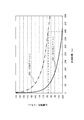
図5は、DSRCビーコン202およびUHFビーコン203の伝搬損失特性を示す図である。
図5に示すように、UHFビーコン203はDSRCビーコン202と比較して伝搬距離に対する電界強度の損失(伝搬損失)が小さい。
例えば、伝搬距離が400メートルの地点でもUHFビーコン203の伝搬損失は「−80dBm」程度であるため、UHFビーコン203はUHFビーコン装置112から400メートル離れた地点でも車載器ではUHFビーコン情報を受信できる。FIG. 5 is a diagram illustrating the propagation loss characteristics of the
As shown in FIG. 5, the UHF beacon 203 has a smaller loss of electric field strength (propagation loss) with respect to the propagation distance than the
For example, since the propagation loss of the UHF beacon 203 is about “−80 dBm” even at a point where the propagation distance is 400 meters, the UHF beacon 203 can receive UHF beacon information at a
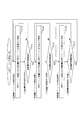
図6は、実施の形態2におけるUHFビーコン装置112によるUHFビーコン信号の発信方法を示すフローチャートである。
図7は、実施の形態2におけるUHFビーコン信号の時分割、周波数分割および送信出力を示す図である。
1台のUHFビーコン装置112により、各ゾーンに異なる交通情報を配信する方法について、図6および図7に基づいて以下に説明する。FIG. 6 is a flowchart showing a method of transmitting a UHF beacon signal by UHF beacon device 112 in the second embodiment.
FIG. 7 is a diagram illustrating time division, frequency division, and transmission output of a UHF beacon signal in the second embodiment.
A method of distributing different traffic information to each zone by using one UHF beacon device 112 will be described below with reference to FIGS.
<S110:近距離ゾーンへの発信処理>
UHFビーコン装置112は、近距離向けの交通情報を設定した周波数f1のUHFビーコン信号を所定の低電力(図7では、10ミリワット)で発信する。
以下、近距離向けの交通情報が設定されたUHFビーコン信号を近距離用UHFビーコン信号という。
近距離用UHFビーコン信号は、低電力で発信されるため、近距離ゾーン291までしか到達せず、中距離ゾーン292および遠距離ゾーン293には到達しない。
近距離ゾーン291を走行している車両の車載器は受信周波数をf1にすることにより近距離用UHFビーコン信号を受信し、近距離向けの交通情報を取得することができる。<S110: Call processing to short-distance zone>
The UHF beacon device 112 transmits a UHF beacon signal having a frequency f1 in which traffic information for a short distance is set at a predetermined low power (10 milliwatts in FIG. 7).
Hereinafter, a UHF beacon signal in which traffic information for a short distance is set is referred to as a short-range UHF beacon signal.
Since the short-range UHF beacon signal is transmitted with low power, the short-range UHF beacon signal reaches only the short-distance zone 291 and does not reach the medium-distance zone 292 and the long-distance zone 293.
The vehicle-mounted device of the vehicle traveling in the short distance zone 291 can receive the short distance UHF beacon signal by setting the reception frequency to f1, and can acquire traffic information for short distance.
<S111:近距離用時間待ち処理>
UHFビーコン装置112は、近距離向けの交通情報の発信時間として予め定められた近距離用時間(図7では、6ミリ秒[=0.6周期])の経過を待ち、近距離用時間が経過するまで近距離ゾーンへの発信処理(S110)を続ける。近距離用時間は近距離用のタイムスロットともいう。<S111: Short-distance time waiting process>
The UHF beacon device 112 waits for the short distance time (6 milliseconds [= 0.6 period] in FIG. 7), which is predetermined as the transmission time of traffic information for short distance, to wait for the short distance time. The transmission process to the short-distance zone (S110) is continued until the time has elapsed. The short distance time is also referred to as a short distance time slot.
<S120:中距離ゾーンへの発信処理>
UHFビーコン装置112は、中距離向けの交通情報を設定した周波数f2のUHFビーコン信号を所定の中程度の電力(図7では、40ミリワット)で発信する。
以下、中距離向けの交通情報が設定されたUHFビーコン信号を中距離用UHFビーコン信号という。
中距離用UHFビーコン信号は、中程度の電力で発信されるため、中距離ゾーン292までしか到達せず、遠距離ゾーン293には到達しない。
中距離ゾーン292を走行している車両の車載器は受信周波数をf2にすることにより中距離用UHFビーコン信号を受信し、中距離向けの交通情報を取得することができる。<S120: Call processing to medium distance zone>
The UHF beacon device 112 transmits a UHF beacon signal having a frequency f2 in which traffic information for a medium distance is set with a predetermined medium power (40 milliwatts in FIG. 7).
Hereinafter, the UHF beacon signal in which the traffic information for the medium distance is set is referred to as a medium-range UHF beacon signal.
Since the medium-range UHF beacon signal is transmitted with medium power, it reaches only the medium-distance zone 292 and does not reach the long-distance zone 293.
The vehicle-mounted device of the vehicle traveling in the intermediate distance zone 292 can receive the intermediate distance UHF beacon signal by setting the reception frequency to f2, and can acquire the traffic information for the intermediate distance.
<S121:中距離用時間待ち処理>
UHFビーコン装置112は、中距離向けの交通情報の発信時間として予め定められた中距離用時間(図7では、3ミリ秒[=0.3周期])の経過を待ち、中距離用時間が経過するまで中距離ゾーンへの発信処理(S120)を続ける。中距離用時間は中距離用のタイムスロットともいう。<S121: Waiting process for intermediate distance>
The UHF beacon device 112 waits for the elapse of the intermediate distance time (3 milliseconds [= 0.3 cycle] in FIG. 7) that is predetermined as the transmission time of the traffic information for the intermediate distance, The transmission process to the middle distance zone (S120) is continued until the time has elapsed. The medium distance time is also referred to as a medium distance time slot.
<S130:遠距離ゾーンへの発信処理>
UHFビーコン装置112は、遠距離向けの交通情報を設定した周波数f3のUHFビーコン信号を所定の高電力(図7では、100ミリワット)で発信する。
以下、遠距離向けの交通情報が設定されたUHFビーコン信号を遠距離用UHFビーコン信号という。
遠距離ゾーン293を走行している車両の車載器は受信周波数をf3にすることにより遠距離用UHFビーコン信号を受信し、遠距離向けの交通情報を取得することができる。<S130: Call processing to long-distance zone>
The UHF beacon device 112 transmits a UHF beacon signal having a frequency f3 in which traffic information for a long distance is set at a predetermined high power (100 milliwatts in FIG. 7).
Hereinafter, a UHF beacon signal in which traffic information for a long distance is set is referred to as a long-range UHF beacon signal.
The vehicle-mounted device of the vehicle traveling in the long-distance zone 293 can receive the long-range UHF beacon signal by setting the reception frequency to f3, and can acquire traffic information for long-distance.
<S131:遠距離用時間待ち処理>
UHFビーコン装置112は、遠距離向けの交通情報の発信時間として予め定められた遠距離用時間(図7では、1ミリ秒[=0.1周期])の経過を待ち、遠距離用時間が経過するまで遠距離ゾーンへの発信処理(S130)を続ける。遠距離用時間は遠距離用のタイムスロットともいう。<S131: Long Distance Time Waiting Process>
The UHF beacon device 112 waits for the elapse of a long distance time (1 millisecond [= 0.1 period] in FIG. 7) as a transmission time of traffic information for a long distance, and the long distance time The outgoing call processing to the long-distance zone (S130) is continued until the time has elapsed. The long distance time is also called a long time slot.
UHFビーコン装置112は、S110〜S131の処理を1周期(例えば、10ミリ秒)として繰り返し実行する。 The UHF beacon device 112 repeatedly executes the processing of S110 to S131 as one cycle (for example, 10 milliseconds).
上記のように時分割で各ゾーン向けの交通情報を配信することにより、各ゾーンに異な
る交通情報を1台のUHFビーコン装置112で配信することができ、UHFビーコン装置112の数量を減らし、システムのコストを削減することができる。
但し、UHFビーコン装置112をゾーンの数だけ設け、各UHFビーコン装置112それぞれから同時間帯に、異なるゾーン用のUHFビーコン信号を異なる周波数で配信してもよい。
また、近距離用UHFビーコンおよび中距離用UHFビーコンの送信出力を高電力にしないことにより、消費電力を削減することができる。
なお図7に示すように、近距離用時間を6ミリ秒、中距離用時間を3ミリ秒、遠距離用時間を1ミリ秒として1周期としたが、近距離ゾーン291、中距離ゾーン292、遠距離ゾーン293に対して出力する情報量に応じて、近距離用時間、中距離用時間、遠距離用時間の秒数の割合を変えてもよい。また1周期は、10ミリ秒以外の秒数でも構わない。By distributing the traffic information for each zone in a time-sharing manner as described above, different traffic information can be distributed to each zone by one UHF beacon device 112, the number of UHF beacon devices 112 is reduced, and the system The cost can be reduced.
However, UHF beacon devices 112 may be provided for the number of zones, and UHF beacon signals for different zones may be distributed at different frequencies from the respective UHF beacon devices 112 in the same time zone.
Moreover, power consumption can be reduced by not setting the transmission output of the short-range UHF beacon and the medium-range UHF beacon to high power.
As shown in FIG. 7, the short distance time is 6 milliseconds, the medium distance time is 3 milliseconds, and the long distance time is 1 millisecond, which is one cycle, but the short distance zone 291 and the medium distance zone 292 Depending on the amount of information output to the long distance zone 293, the ratio of the number of seconds of the short distance time, the medium distance time, and the long distance time may be changed. One period may be a number of seconds other than 10 milliseconds.
図8は、実施の形態2における車載器の動作方法を示すフローチャートである。
遠くの地点から交差点193に向けて走行する車両の車載器の動作について、図8に基づいて以下に説明する。FIG. 8 is a flowchart showing an operation method of the vehicle-mounted device in the second embodiment.
The operation of the vehicle-mounted device of the vehicle that travels from a distant point toward the intersection 193 will be described below with reference to FIG.
<S210:遠距離交通情報受信処理>
交差点193に向けて走行している車両が遠距離ゾーン293に差し掛かったとき、車載器は、受信周波数を遠距離ゾーン293用の周波数f3にし、遠距離用UHFビーコン信号を受信する。そして、車載器は、遠距離用UHFビーコンから遠距離向けの交通情報を取得する。
例えば、車載器は、車両が遠距離ゾーン293に差し掛かったか否かを、カーナビのGPS(Global Positioning System)で測位された測位結果と、交差点193に設置されていたUHFビーコン装置112から配信された交通情報とに基づいて判定する。
遠距離向けの交通情報には、DSSSのシステム情報として、各ゾーンの範囲が交差点193またはUHFビーコン装置112からの距離、各ゾーンの半径、絶対座標などで示されている。<S210: Long-distance traffic information reception processing>
When the vehicle traveling toward the intersection 193 reaches the long distance zone 293, the vehicle-mounted device sets the reception frequency to the frequency f3 for the long distance zone 293 and receives the long distance UHF beacon signal. And the onboard equipment acquires the traffic information for long distances from the UHF beacon for long distances.
For example, the in-vehicle device is delivered from the positioning result measured by the GPS (Global Positioning System) of the car navigation system and the UHF beacon device 112 installed at the intersection 193 as to whether or not the vehicle has approached the long-distance zone 293. Judgment based on traffic information.
In the long-distance traffic information, the range of each zone is indicated by the distance from the intersection 193 or the UHF beacon device 112, the radius of each zone, absolute coordinates, and the like as DSSS system information.
さらに、遠距離向けの交通情報には、遠距離ゾーン293の道路情報が含まれる。車載器は、道路情報に基づいて車両の現在位置を測位する。 Further, the long-distance traffic information includes road information of the long-distance zone 293. The vehicle-mounted device measures the current position of the vehicle based on the road information.
例えば、道路情報には、道路上の地物(道路標識、道路標示、白線など)の座標値が含まれる。また、車両には、走行中の道路を撮像するカメラ、車両の姿勢角を計測するジャイロおよびGPS測位するGPS受信機が取り付けられている。
まず、車載器は、カメラにより撮像された画像を画像処理し、画像に映っている道路上の地物を識別する。次に、車載器は、GPSの測位結果を取得する(または、ジャイロの計測値および速度計の計測値に基づくデッドレコニング処理により車両の現在位置を測位する)。
次に、車載器は、車両の現在位置、車両の姿勢角およびカメラの焦点距離に基づいて、カメラにより撮像された画像に映っている撮像範囲の座標を算出すると共に、画像に映っているものとして識別した道路上の地物の座標を算出する。カメラにより撮像された画像は、3次元空間の地物を、カメラ中心からカメラの視線方向に向けて焦点距離だけ離れてカメラの視線方向と直交する2次元の撮像面に投影したものである。また、カメラ中心は、車両の現在位置と車両中心に対するカメラの取付オフセット(相対位置)とに基づいて定まる。また、カメラの視線方向は、車両の姿勢角と車両に対するカメラの取付オフセット(相対姿勢角)とに基づいて定まる。これにより、車両の現在位置、車両の姿勢角およびカメラの焦点距離が求まれば、道路標示や白線のように路面に位置していることが分かっている地物について、3次元の座標値を画像に基づいて算出することができる。
次に、車載器は、カメラの撮像範囲の座標に基づいて、画像に映っている道路上の地物の座標値を道路地図情報から抽出する。
そして、車載器は、道路上の地物の座標の算出値と抽出値との差分に基づいて、GPSやデッドレコニングによる測位結果を補正し、車両の現在位置を算出する。
上記方法により車両の現在位置を測位する自己位置標定装置を車載器とは別に車両に備えてもよい。
これにより、遠距離ゾーン293に光ビーコン装置121を設置しなくても、車載器に車両の位置を特定させることができる。For example, the road information includes coordinate values of features on the road (road signs, road markings, white lines, etc.). In addition, a camera that captures an image of a running road, a gyro that measures the attitude angle of the vehicle, and a GPS receiver that performs GPS positioning are attached to the vehicle.
First, the vehicle-mounted device performs image processing on an image captured by a camera, and identifies features on the road that are reflected in the image. Next, the vehicle-mounted device acquires the positioning result of GPS (or measures the current position of the vehicle by dead reckoning processing based on the measured value of the gyro and the measured value of the speedometer).
Next, the vehicle-mounted device calculates the coordinates of the imaging range shown in the image taken by the camera based on the current position of the vehicle, the attitude angle of the vehicle, and the focal length of the camera, and is shown in the image The coordinates of the feature on the road identified as is calculated. The image picked up by the camera is obtained by projecting a feature in the three-dimensional space onto a two-dimensional image pickup plane that is away from the camera center by the focal length in the line-of-sight direction of the camera and orthogonal to the line-of-sight direction of the camera. The camera center is determined based on the current position of the vehicle and the camera mounting offset (relative position) with respect to the vehicle center. Further, the viewing direction of the camera is determined based on the posture angle of the vehicle and the camera mounting offset (relative posture angle) with respect to the vehicle. As a result, once the current position of the vehicle, the attitude angle of the vehicle, and the focal length of the camera are obtained, three-dimensional coordinate values are obtained for features that are known to be located on the road surface, such as road markings and white lines. It can be calculated based on the image.
Next, the vehicle-mounted device extracts the coordinate value of the feature on the road shown in the image from the road map information based on the coordinates of the imaging range of the camera.
Then, the vehicle-mounted device corrects the positioning result by GPS or dead reckoning based on the difference between the calculated value of the coordinates of the feature on the road and the extracted value, and calculates the current position of the vehicle.
The vehicle may be provided with a self-positioning device that measures the current position of the vehicle by the above method, separately from the vehicle-mounted device.
Thereby, even if it does not install the optical beacon device 121 in the long-distance zone 293, the vehicle-mounted device can specify the position of the vehicle.
<S211:中距離ゾーン進入判定処理>
次に、車載器は、車両の現在位置と遠距離向けの交通情報に設定されている中距離ゾーン292の範囲とに基づいて、車両が中距離ゾーン292に進入したか否かを判定する。
車両が中距離ゾーン292に進入するまでの間、つまり、車両が遠距離ゾーン293を走行している間、遠距離交通情報受信処理(S210)が実行される。<S211: Middle distance zone entry determination process>
Next, the vehicle-mounted device determines whether or not the vehicle has entered the intermediate distance zone 292 based on the current position of the vehicle and the range of the intermediate distance zone 292 set in the traffic information for a long distance.
Until the vehicle enters the intermediate distance zone 292, that is, while the vehicle travels in the long distance zone 293, the long distance traffic information reception process (S210) is executed.
<S220:中距離交通情報受信処理>
S211において車両が中距離ゾーン292に進入した場合、車載器は、遠距離向けの交通情報に設定されていた中距離ゾーン292用の周波数f2に受信周波数を変更し、中距離用UHFビーコン信号を受信する。そして、車載器は、中距離用UHFビーコンから中距離向けの交通情報を取得する。<S220: Medium distance traffic information reception processing>
When the vehicle enters the intermediate distance zone 292 in S211, the vehicle-mounted device changes the reception frequency to the frequency f2 for the intermediate distance zone 292 set in the traffic information for the long distance, and transmits the UHF beacon signal for the intermediate distance. Receive. And the onboard equipment acquires the traffic information for medium distances from the UHF beacon for medium distances.
中距離向けの交通情報には、中距離ゾーン292の道路情報や近距離ゾーン291の交通制限情報が設定されている。 In the medium-distance traffic information, road information in the medium-distance zone 292 and traffic restriction information in the short-distance zone 291 are set.
車載器は、近距離ゾーン291の交通制限情報に基づいて、各種の注意喚起メッセージをカーナビの画面に表示し、または、音声出力する。
例えば、車載器は、交通制限情報が渋滞や事故や道路工事が交差点193で発生していることを示す場合、交差点193に近づいて速度を落とした前方車両への追突を防ぐために、追突防止用の注意喚起メッセージを表示または音声出力する。
また、車載器は、遠距離交通情報受信処理(S210)と同様に、中距離ゾーン292の道路情報に基づいて、車両の現在位置を測位する。
これにより、中距離ゾーン292に光ビーコン装置121を設置しなくても、車載器に車両の位置を特定させることができる。The vehicle-mounted device displays various alerting messages on the screen of the car navigation or outputs a voice based on the traffic restriction information of the short distance zone 291.
For example, when the traffic restriction information indicates that a traffic jam, an accident, or road construction is occurring at the intersection 193, the on-vehicle device is used for preventing a rear-end collision in order to prevent a rear-end collision with a vehicle approaching the intersection 193 and reducing the speed. Display or output the alert message.
In addition, the vehicle-mounted device measures the current position of the vehicle based on the road information of the intermediate distance zone 292, as in the long-distance traffic information reception process (S210).
Thereby, even if the optical beacon device 121 is not installed in the intermediate distance zone 292, the vehicle-mounted device can specify the position of the vehicle.
<S221:近距離ゾーン進入判定処理>
次に、車載器は、車両の現在位置と遠距離向けの交通情報に設定されていた近距離ゾーン291の範囲とに基づいて、車両が近距離ゾーン291に進入したか否かを判定する。
車両が近距離ゾーン291に進入するまでの間、つまり、車両が中距離ゾーン292を走行している間、中距離交通情報受信処理(S220)が実行される。<S221: Short-distance zone entry determination process>
Next, the vehicle-mounted device determines whether or not the vehicle has entered the short-distance zone 291 based on the current position of the vehicle and the range of the short-distance zone 291 set in the long-distance traffic information.
Until the vehicle enters the short distance zone 291, that is, while the vehicle travels in the medium distance zone 292, the medium distance traffic information reception process (S 220) is executed.
<S230:近距離交通情報受信処理>
S221において車両が近距離ゾーン291に進入した場合、車載器は、遠距離向けの交通情報に設定されていた近距離ゾーン291用の周波数f1に受信周波数を変更し、近距離用UHFビーコン信号を受信する。そして、車載器は、近距離用UHFビーコンから近距離向けの交通情報を取得する。
さらに、車載器は、交差点193に設置されているDSRCビーコン装置111からDSRCビーコン信号を受信し、DSRCビーコン信号から交通情報を取得する。DSRCビーコンの交通情報は、近距離向けの交通情報である。但し、UHFビーコンより伝送速度が速いDSRCビーコンの交通情報には、UHFビーコンの交通情報に加えて、画像や音声その他の付加情報が含まれている。但し、DSRCビーコンは、直進性が強く回折特
性が低いため、前方を大型車両が走行している場合など、DSRCビーコン装置111と車両との間に遮蔽物が存在する場合、必ずしも車載器により受信されるとは限らない。
さらに、車載器は、交差点193の手前に設置されている光ビーコン装置121の下方を車両が通過する際、光ビーコン信号を受信し、光ビーコンから交通情報を取得する。<S230: Short distance traffic information reception processing>
When the vehicle enters the short-distance zone 291 in S221, the vehicle-mounted device changes the reception frequency to the frequency f1 for the short-distance zone 291 set in the traffic information for long-distance, and sends the short-range UHF beacon signal. Receive. And the onboard equipment acquires the traffic information for near distances from the UHF beacon for short distances.
Furthermore, the vehicle-mounted device receives a DSRC beacon signal from the DSRC beacon device 111 installed at the intersection 193, and acquires traffic information from the DSRC beacon signal. The traffic information of the DSRC beacon is traffic information for a short distance. However, the traffic information of the DSRC beacon whose transmission speed is higher than that of the UHF beacon includes images, voice and other additional information in addition to the traffic information of the UHF beacon. However, since the DSRC beacon has high straightness and low diffraction characteristics, it is not necessarily received by the vehicle-mounted device when there is a shield between the DSRC beacon device 111 and the vehicle, such as when a large vehicle is traveling ahead. It is not always done.
Furthermore, when the vehicle passes below the optical beacon device 121 installed in front of the intersection 193, the vehicle-mounted device receives an optical beacon signal and acquires traffic information from the optical beacon.
近距離向けの交通情報には、対向車の有無、後方を走行する二輪車の有無、横断歩道上の歩行者や自転車の有無、信号機の制御情報などの交差点193のリアルタイムな情報が設定されている。
また、光ビーコンの交通情報には座標値や走行車線などの位置情報が設定されている。In the traffic information for short distance, real-time information of the intersection 193 is set such as the presence / absence of an oncoming vehicle, the presence / absence of a motorcycle traveling behind, the presence / absence of a pedestrian or bicycle on a pedestrian crossing, and traffic signal control information. .
In addition, position information such as coordinate values and travel lanes is set in the traffic information of the optical beacon.
<S231:DSRC受信有無判定処理>
車載器は、S230においてDSRCビーコン装置111からDSRCビーコン信号を受信できたか否かを判定する。<S231: DSRC reception presence / absence determination processing>
The in-vehicle device determines whether or not the DSRC beacon signal has been received from the DSRC beacon device 111 in S230.
<S232:DSRC交通情報受信処理>
S230においてDSRCビーコン信号が受信された場合、車載器は、DSRCビーコンの交通情報に基づいて、各種メッセージをカーナビの画面に表示したり、または、音声出力したりする。また、車載器(または、自動運転制御装置)は、DSRCビーコンの交通情報に基づいて減速、停止、ウィンカーの点滅、ハンドルの操舵などの自動運転制御を行ってもよい。
例えば、車載器は、右折時に対向車との右直事故を防ぐための右折用の注意喚起メッセージを表示または音声出力したり、左折時に二輪車を巻き込むことを防ぐための左折用の注意喚起メッセージを表示または音声出力したり、右左折時に横断歩道上に歩行者や自転車が存在する場合は歩行者や自転車の存在の注意喚起メッセージを表示または音声出力したり、信号機が赤に変わる前に減速を促すメッセージを表示または音声出力したりする。
また例えば、車載器は、信号機が赤に変わる際に車両を減速制御する。
また、車載器は、光ビーコン信号から取得した位置情報に基づいて車両の現在位置を特定する。<S232: DSRC traffic information reception process>
When the DSRC beacon signal is received in S230, the vehicle-mounted device displays various messages on the car navigation screen or outputs a voice based on the traffic information of the DSRC beacon. Moreover, onboard equipment (or automatic driving | operation control apparatus) may perform automatic driving | operation control, such as deceleration, a stop, blink of a blinker, steering of a steering wheel, based on the traffic information of a DSRC beacon.
For example, the on-board device displays or outputs a warning message for turning right to prevent a right-handed accident with an oncoming vehicle when turning right, or a warning message for turning left to prevent a motorcycle from getting involved when turning left. Display or audio output, if there is a pedestrian or bicycle on the pedestrian crossing when turning left or right, display or output a warning message indicating the presence of a pedestrian or bicycle, or slow down before the traffic light turns red Display or voice prompt message.
Further, for example, the vehicle-mounted device performs deceleration control of the vehicle when the traffic light changes to red.
The vehicle-mounted device identifies the current position of the vehicle based on the position information acquired from the optical beacon signal.
<S233:UHF交通情報受信処理>
S230においてDSRCビーコン信号が受信されなかった場合、車載器は、UHFビーコン信号の交通情報に基づいて、DSRC交通情報受信処理(S232)と同様に、各種メッセージを表示または音声出力したり、自動運転制御したりする。
また、車載器は、光ビーコン信号から取得した位置情報に基づいて車両の現在位置を測位する。<S233: UHF traffic information reception processing>
When the DSRC beacon signal is not received in S230, the vehicle-mounted device displays or outputs various messages or performs automatic driving based on the traffic information of the UHF beacon signal, as in the DSRC traffic information reception process (S232). Or control.
The vehicle-mounted device measures the current position of the vehicle based on the position information acquired from the optical beacon signal.
以後、交差点193を通過した車両が近距離ゾーン291から中距離ゾーン292に進入したときには、中距離交通情報受信処理(S220)が実行される。また、車両が中距離ゾーン292から遠距離ゾーン293に進入したとき、および、他の交差点193に設置されているUHFビーコン装置112の遠距離ゾーン293に進入したときには、遠距離交通情報受信処理(S210)が実行される。
これにより、車載器に対して、異なる交通情報を、単一のゾーンおよび単一のUHFビーコン装置112で提供しているかのように、シームレスに提供することができる。Thereafter, when a vehicle that has passed through the intersection 193 enters the intermediate distance zone 292 from the short distance zone 291, the intermediate distance traffic information reception process (S 220) is executed. Further, when the vehicle enters the long-distance zone 293 from the medium-distance zone 292 and when the vehicle enters the long-distance zone 293 of the UHF beacon device 112 installed at another intersection 193, the long-distance traffic information reception process ( S210) is executed.
Thereby, different traffic information can be seamlessly provided to the vehicle-mounted device as if the single zone and the single UHF beacon device 112 are provided.
実施の形態2では、以下のような安全運転支援システム100について説明した。
UHF電波の伝搬損失特性を利用し、DSRCビーコン信号の到達領域より遠距離である領域(交差点193から100m以遠〜400m程度)に対して、UHFビーコン装置112と車載器との通信を可能にする。
これにより、遠距離領域の車両にも、追突防止サービスなどのDSSSサービスを享受させることができる。In the second embodiment, the following safe
Using the propagation loss characteristics of UHF radio waves, communication between the UHF beacon device 112 and the vehicle-mounted device is enabled for an area far from the reach area of the DSRC beacon signal (about 100 m to 400 m from the intersection 193). .
Thereby, it is possible to allow a vehicle in a long-distance area to enjoy a DSSS service such as a rear-end collision prevention service.
また、UHFビーコン装置112の通信領域を同心円状(近距離ゾーン291、中距離ゾーン292、遠距離ゾーン293)に分割し、各同心円状の領域で別々の周波数を用いて、異なる情報を車載器に提供する。
これにより、車両側にシームレスなサービス(複数のサービスを、同じサービスを利用しているかのごとく利用できること)を提供することができる。In addition, the communication area of the UHF beacon device 112 is divided into concentric circles (short-distance zone 291, medium-distance zone 292, long-distance zone 293). To provide.
Thereby, a seamless service (a plurality of services can be used as if the same service is used) can be provided to the vehicle side.
また、車載器は、UHFビーコン信号により提供された道路情報と、自車両に搭載されているGPSによる自車位置の測位結果とにより、自車両の位置を把握する。
これにより、光ビーコン装置121が設置されていない遠距離ゾーン293であっても、車載器は自車両の位置がわかる。Further, the vehicle-mounted device grasps the position of the host vehicle from the road information provided by the UHF beacon signal and the positioning result of the host vehicle position by the GPS mounted on the host vehicle.
Thereby, even if it is the long distance zone 293 where the optical beacon device 121 is not installed, the vehicle-mounted device can know the position of the host vehicle.
実施の形態3.
実施の形態3では、実施の形態1〜実施の形態2の少なくともいずれかで説明した安全運転支援システム100について、車両がどこを走行している場合であっても、車載器が異なる交差点193に設置されている少なくともいずれかのUHFビーコン装置112からUHFビーコン信号を混信せずに受信し、交通情報を得られるようにする形態を説明する。
In
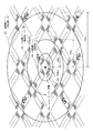
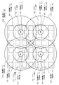
図9は、実施の形態3におけるUHFビーコン装置112の配置関係と発信周波数とを示す図である。
実施の形態3におけるUHFビーコン装置112の配置関係と発信周波数とについて、図9に基づいて以下に説明する。FIG. 9 is a diagram showing the arrangement relationship and the transmission frequency of the UHF beacon device 112 in the third embodiment.
The arrangement relationship and transmission frequency of the UHF beacon device 112 in
隣り合う各UHFビーコン装置112(112a〜112d)は、遠距離ゾーン293(293a〜293d)の少なくとも一部が互いに重なる(通信領域がオーバラップする)と共に、中距離ゾーン292が互いに重ならない程度離れた地点(交差点193)に配置される。
例えば、UHFビーコン装置112から半径200メートルの範囲が中距離ゾーン292であり、UHFビーコン装置112から半径400メートルの範囲が遠距離ゾーン293である場合、各UHFビーコン装置112は互いに400メートルから800メートル離れた地点に、遠距離ゾーン293の少なくとも一部が互いに重なるように配置される。Each adjacent UHF beacon device 112 (112a to 112d) is separated such that at least a part of the long-distance zone 293 (293a to 293d) overlaps with each other (communication areas overlap) and the intermediate-distance zone 292 does not overlap with each other. Is located at the intersection (intersection 193).
For example, if the range of 200 meters radius from the UHF beacon device 112 is the medium distance zone 292 and the range of 400 meters radius from the UHF beacon device 112 is the long distance zone 293, each UHF beacon device 112 is 400 meters to 800 feet from each other. At a point distant from the meter, at least a part of the long-distance zone 293 is arranged so as to overlap each other.
さらに、各UHFビーコン装置112は、UHFビーコン信号がゾーンの重なり合う部分で混信(干渉)しないように、遠距離用UHFビーコン用に異なる周波数が割り当てられている。
また、各UHFビーコン装置112は、中距離ゾーン292および近距離ゾーン291が重なり合わないように配置されているため、中距離用UHFビーコンおよび近距離用UHFビーコン用に互いに共通する周波数が割り当てられている。
例えば、UHFビーコン装置112a、UHFビーコン装置112b、UHFビーコン装置112cおよびUHFビーコン装置112dはそれぞれ、近距離用UHFビーコン用に周波数f1が割り当てられ、中距離用UHFビーコン用に周波数f2が割り当てられている。
また例えば、遠距離用UHFビーコン用に、UHFビーコン装置112aには周波数f3、UHFビーコン装置112bには周波数f4、UHFビーコン装置112cには周波数f5、UHFビーコン装置112dには周波数f6がそれぞれに割り当てられている。
周波数f1〜f6は、各UHFビーコン装置112に対して、予め、設定される情報である。Furthermore, each UHF beacon device 112 is assigned a different frequency for the UHF beacon for long distances so that the UHF beacon signal does not interfere (interfere) in the overlapping zone.
In addition, since each UHF beacon device 112 is arranged so that the medium-distance zone 292 and the short-distance zone 291 do not overlap, a common frequency is assigned to the medium-distance UHF beacon and the short-distance UHF beacon. ing.
For example,
Also, for example, for the UHF beacon for long distance, the frequency f3 is assigned to the
The frequencies f1 to f6 are information set in advance for each UHF beacon device 112.
UHFビーコン装置112a〜UHFビーコン装置112dの周囲に配置されるUHF
ビーコン装置112(図示省略)も同様に配置され、同様にUHFビーコンの周波数が割り当てられている。
例えば、図9において、UHFビーコン装置112bの上隣りに遠距離ゾーン293のみが重なるように配置されたUHFビーコン装置112には、UHFビーコン装置112dと同じ周波数を割り当てればよい。
また例えば、図9において、UHFビーコン装置112bの右隣りに遠距離ゾーン293のみが重なるように配置されたUHFビーコン装置112には、UHFビーコン装置112aと同じ周波数を割り当てればよい。
また例えば、図9において、UHFビーコン装置112bの右斜め上隣りに遠距離ゾーン293のみが重なるように配置されたUHFビーコン装置112には、UHFビーコン装置112cと同じ周波数を割り当てればよい。
ここで、UHFビーコン装置112bの下隣りをUHFビーコン装置112dとし、UHFビーコン装置112bの左隣りをUHFビーコン装置112aとし、UHFビーコン装置112bの左斜め下隣りをUHFビーコン装置112cとする。UHF arranged around
The beacon device 112 (not shown) is also arranged in the same manner, and the frequency of the UHF beacon is similarly assigned.
For example, in FIG. 9, the same frequency as that of the
Further, for example, in FIG. 9, the same frequency as that of the
Further, for example, in FIG. 9, the same frequency as that of the
Here, the lower neighbor of the
図10は、実施の形態3におけるUHFビーコン装置112に割り当てる周波数帯を示す図である。
実施の形態3におけるUHFビーコン装置112に割り当てる周波数帯(チャネル)について、図10に基づいて以下に説明する。FIG. 10 is a diagram illustrating frequency bands assigned to the UHF beacon device 112 in the third embodiment.
The frequency band (channel) assigned to the UHF beacon device 112 in the third embodiment will be described below based on FIG.
例えば、DSSSで用いる周波数帯域を約715.0〜725.0MHz(メガヘルツ)までの約10.0MHzとする。この周波数帯域は、テレビの地上波アナログ放送に使用されている帯域であり、2012年7月25日以降の地上波アナログ放送の終了後に使用可能になる。
また、周波数帯715.0〜725.0MHzと前後する周波数帯を用いる他のシステムとの混信を避けるため、前後に約5.0MHzのガードバンド(710.0〜715.0MHzと725.0〜730.0MHz)を設ける。For example, the frequency band used in DSSS is about 10.0 MHz up to about 715.0 to 725.0 MHz (megahertz). This frequency band is a band used for the terrestrial analog broadcasting of the television, and can be used after the terrestrial analog broadcasting after July 25, 2012 is completed.
Also, in order to avoid interference with other systems using frequency bands 715.0 to 725.0 MHz and the frequency band before and after, about 5.0 MHz guard bands (710.0 to 715.0 MHz and 725.0 to 730.0 MHz).
図9に示したように各ゾーン用のUHFビーコンを混信させないためには6つの周波数帯f1〜f6が必要になる。そこで、DSSSで用いる10.0MHz帯を互いに重ならない6つの帯域に分割する。前記の各周波数f1〜f6は、所定の幅を持つ周波数帯f1〜f6を意味するものとする。
例えば、各周波数帯f1〜f6それぞれに1.5MHzの帯域を割り当て、各周波数帯のギャップ(間隔)に0.2MHzの帯域を割り当てる。
これにより、周波数帯f1〜f6にはそれぞれ、約715.0〜716.5MHz、約716.7〜718.2MHz、約718.4〜719.9MHz、約720.1〜721.6MHz、約721.8〜723.3MHz、約723.5〜725.0MHzが割り当てられる。
また、周波数帯f1〜f6の中心周波数はそれぞれ、約715.75MHz、約717.45MHz、約719.15MHz、約720.85MHz、約722.55MHz、約724.25MHzとなる。As shown in FIG. 9, six frequency bands f1 to f6 are required in order to prevent the UHF beacon for each zone from interfering. Therefore, the 10.0 MHz band used in DSSS is divided into six bands that do not overlap each other. Each of the frequencies f1 to f6 means frequency bands f1 to f6 having a predetermined width.
For example, a 1.5 MHz band is allocated to each of the frequency bands f1 to f6, and a 0.2 MHz band is allocated to the gap (interval) of each frequency band.
As a result, the frequency bands f1 to f6 are about 715.0 to 716.5 MHz, about 716.7 to 718.2 MHz, about 718.4 to 719.9 MHz, about 720.1 to 721.6 MHz, and about 721, respectively. .8-723.3 MHz, approximately 723.5-725.0 MHz are allocated.
The center frequencies of the frequency bands f1 to f6 are about 715.75 MHz, about 717.45 MHz, about 719.15 MHz, about 720.85 MHz, about 722.55 MHz, and about 724.25 MHz, respectively.
実施の形態3では、以下のような安全運転支援システム100について説明した。
複数あるUHFビーコン装置112に対して、UHFビーコン装置112の通信領域のうち中距離ゾーン292(中間領域)および近距離ゾーン291(内領域)の周波数は、各UHFビーコン装置112で同一にする。また、遠距離ゾーン293(外領域)の周波数は、隣接するUHFビーコン装置112の外領域の周波数と異なる周波数とする。
このような周波数配置により、UHFビーコン装置112を通信領域がオーバラップするように配置しても、周波数干渉を防止することができる。In the third embodiment, the following safe
With respect to a plurality of UHF beacon devices 112, the frequencies of the medium distance zone 292 (intermediate region) and the short distance zone 291 (inner region) in the communication region of the UHF beacon device 112 are made the same in each UHF beacon device 112. The frequency of the long-distance zone 293 (outer region) is different from the frequency of the outer region of the adjacent UHF beacon device 112.
With such a frequency arrangement, frequency interference can be prevented even if the UHF beacon device 112 is arranged so that the communication areas overlap.
実施の形態4.
実施の形態4では、実施の形態1〜実施の形態3の少なくともいずれかで説明した安全運転支援システム100について、車載器からUHFビーコン信号を発信し、車両側で検出された警告情報をUHFビーコン装置112に通知し、UHFビーコン装置112が車載器から通知された警告情報を他の車両に配信する形態を説明する。Embodiment 4 FIG.
In the fourth embodiment, the UHF beacon signal is transmitted from the vehicle-mounted device for the safe
例えば、前方で事故が発生した場合、ドライバーはハザードボタン(または、専用に設けられた警告ボタン)(入力機器の一例)を押下する。
ハザードボタンが押下されたとき、車載器は警告を示す警告情報を設定してUHFビーコン信号を発信する。
車載器から発信されたUHFビーコン信号を受信したUHFビーコン装置112は、警告情報を設定して近距離ゾーン291用、中距離ゾーン292用および遠距離ゾーン293用の各UHFビーコン信号を発信する。
これにより、車両側で検出された警告情報(例えば、事故情報)を遠距離ゾーン293を走行する車両にも提供することができる。For example, when an accident occurs ahead, the driver presses a hazard button (or a dedicated warning button) (an example of an input device).
When the hazard button is pressed, the vehicle-mounted device sets warning information indicating a warning and transmits a UHF beacon signal.
The UHF beacon device 112 that has received the UHF beacon signal transmitted from the vehicle-mounted device sets warning information and transmits each UHF beacon signal for the short distance zone 291, the intermediate distance zone 292, and the long distance zone 293.
Thereby, warning information (for example, accident information) detected on the vehicle side can be provided to a vehicle traveling in the long-distance zone 293.
例えば、車載器は、現在の受信周波数を用いてUHFビーコン信号を発信する。
また例えば、UHFビーコン装置112が近距離と遠距離との2つのゾーンに交通情報を配信するシステムにおいて、車載器は、使用されていない中距離用の周波数f2を用いてUHFビーコン信号を発信する。
また例えば、車載器は、その他の専用の周波数を用いてUHFビーコン(または、その他の周波数帯のビーコン)信号を発信してもよい。For example, the vehicle-mounted device transmits a UHF beacon signal using the current reception frequency.
In addition, for example, in the system in which the UHF beacon device 112 distributes traffic information to two zones, a short distance and a long distance, the vehicle-mounted device transmits a UHF beacon signal using the frequency f2 for intermediate distance that is not used. .
Further, for example, the vehicle-mounted device may transmit a UHF beacon (or beacon in other frequency band) signal using another dedicated frequency.
実施の形態4では、以下のような安全運転支援システム100について説明した。
突発事故の発生時、専用周波数チャネルを用いて、ある車両から全車両にUHFビーコン装置112を介して緊急情報(警告情報)を提供する。
これにより、遠距離ゾーン293の車両に対しても、突発事故の発生を通知することができる。In the fourth embodiment, the following safe
When a sudden accident occurs, emergency information (warning information) is provided from a certain vehicle to all the vehicles via the UHF beacon device 112 using a dedicated frequency channel.
Thereby, the occurrence of a sudden accident can be notified to the vehicle in the long-distance zone 293.
実施の形態5.
実施の形態5では、実施の形態1〜実施の形態4の少なくともいずれかで説明した安全運転支援システム100について、UHFに比べて直進性が強いDSRCビーコン信号を発信するDSRCビーコン装置111の配置方法を説明する。Embodiment 5 FIG.
In the fifth embodiment, the arrangement method of the DSRC beacon device 111 that transmits a DSRC beacon signal that is more straight ahead than UHF is provided for the safe
<実施例5−1>
図11は、実施の形態5におけるDSRCビーコン装置111の配置方法1を示す図である。
実施の形態5におけるDSRCビーコン装置111の配置方法1について、図11に基づいて以下に説明する。<Example 5-1>
FIG. 11 is a diagram illustrating a
The
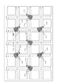
十字路の交差点193において、2つのDSRCビーコン装置111(111a、111b)は、1つの道路(例えば、従道路192)を跨いた略対向の位置に配置され、交差点の互いに交差する対角方向に向けて設置される。
そして、各DSRCビーコン装置111は交差点内に向けて互いに交差する対角方向にDSRCビーコンを発信する。At the intersection 193 of the crossroads, the two DSRC beacon devices 111 (111a, 111b) are arranged at substantially opposite positions across one road (for example, the secondary road 192), and are directed in a diagonal direction where the intersections intersect each other. Installed.
Each DSRC beacon device 111 transmits a DSRC beacon in a diagonal direction that intersects each other toward the intersection.
例えば、DSRCビーコン装置111bは、主道路191の流入方路2から交差点に差し掛かる部分に設置され、主道路191の流入方路0から従道路192の流出方路3に向けて右折する車両199cが交差点に進入したときに車両199cと正対(対向)する方向からDSRCビーコンを発信する。
正対する方向から伝搬するDSRCビーコンの電界強度は高いため、DSRCビーコン装置111bは、交通情報を設定したDSRCビーコン信号をより確実に車両199cの車載器に受信させることができる。For example, the
Since the electric field strength of the DSRC beacon propagating from the opposite direction is high, the
例えば、路側制御装置130が、光ビーコン装置121からの情報に基づいて、主道路191を流入方路2から流出方路0に向けて直進する二輪車両199dが存在することを示す交通情報を生成した場合、この交通情報はDSRCビーコン装置111bからDSRCビーコン信号が発信され、主道路191の流入方路0から従道路192の流出方路3に右折する車両199cの車載器により受信される。DSRCビーコン信号を受信した車載器は、DSRCビーコン信号に設定されている交通情報に基づいて、右直事故防止用のメッセージを表示または音声出力し、ドライバーに注意喚起する。これにより、車両199cと二輪車両199dとの右直事故を防ぐことができる。
For example, the road-side control device 130 generates traffic information indicating that there is a two-wheeled vehicle 199d that travels straight from the
同様に、DSRCビーコン装置111aは、従道路192の流入方路3から交差点に差し掛かる部分に設置され、従道路192の流入方路1から主道路191の流出方路0に向けて右折する車両199(図示省略)が交差点に進入したときに当該車両199と正対する方向からDSRCビーコン信号を発信し、車両199の右直事故を防止する。
Similarly, the
但し、DSRCビーコン装置111aおよびDSRCビーコン装置111bからのDSRCビーコン信号は、特定方路からの右折車両の車載器にのみ受信されるわけではなく、直進車両、左折車両および他の方路からの右折車両の車載器にも受信される。
また、DSRCビーコン装置111aおよびDSRCビーコン装置111bからのDSRCビーコン信号に設定される交通情報は、右直事故防止用の交通情報に限られない。However, the DSRC beacon signals from the
Further, the traffic information set in the DSRC beacon signal from the
DSRCビーコン装置111aとDSRCビーコン装置111bとは、混信を防ぐために、異なるDSRCビーコン信号を異なる周波数帯を用いて発信する。
The
DSRCビーコンには、5.8GHz(ギガヘルツ)帯が用いられる。
5.8GHz帯は、5.795GHz(F1)、5.805GHz(F2)、5.800GHz(F3)、5.790GHz(F4)、5.785GHz(F5)、5.780GHz(F6)、5.775GHz(F7)をそれぞれの中心周波数とする7つの周波数帯(F1〜F7)に分割される。
周波数帯F1と周波数帯F2とは、ETC(Electronic Toll Collection)に用いられている。The DSRC beacon uses a 5.8 GHz (gigahertz) band.
The 5.8 GHz band is 5.795 GHz (F1), 5.805 GHz (F2), 5.800 GHz (F3), 5.790 GHz (F4), 5.785 GHz (F5), 5.780 GHz (F6), 5. The frequency band is divided into seven frequency bands (F1 to F7) having 775 GHz (F7) as the respective center frequencies.
The frequency band F1 and the frequency band F2 are used for ETC (Electronic Toll Collection).
例えば、DSRCビーコン装置111aはDSRCビーコン信号を周波数帯F3を用いて発信し、DSRCビーコン装置111bはDSRCビーコン信号を周波数帯F4を用いて発信する。
For example, the
図12は、実施の形態5におけるDSRCビーコン装置111の配置図1である。
図12に示すように、DSRCビーコン装置111aとDSRCビーコン装置111bとは各交差点(例えば、交差点の一つ置き)に配置される。
DSRCビーコン装置111aは、周波数帯F3を用いてDSRCビーコン信号を発信して、点線で示す車線を走行する車両の車載器に対して交通情報を提供する。
DSRCビーコン装置111bは、周波数帯F4を用いてDSRCビーコン信号を発信して、一点鎖線で示す車線を走行する車両の車載器に対して交通情報を提供する。FIG. 12 is a layout diagram 1 of the DSRC beacon device 111 according to the fifth embodiment.
As shown in FIG. 12, the
The
The
<実施例5−2>
図13は、実施の形態5におけるDSRCビーコン装置111の配置方法2を示す図である。
実施の形態5におけるDSRCビーコン装置111の配置方法2について、図13に基づいて以下に説明する。<Example 5-2>
FIG. 13 is a diagram illustrating a
The
十字路の交差点193において、2つのDSRCビーコン装置111(111a、111b)は、対角方向の角部分に配置され、互いに対向して配置される。
そして、各DSRCビーコン装置111は交差点内に向けて互いに対向する対角方向にDSRCビーコン信号を発信する。At the intersection 193 of the crossroads, the two DSRC beacon devices 111 (111a and 111b) are arranged at the corners in the diagonal direction and arranged to face each other.
Each DSRC beacon device 111 transmits a DSRC beacon signal in a diagonal direction facing each other toward the intersection.
例えば、DSRCビーコン装置111bは、主道路191の流入方路2から交差点193に差し掛かる部分に設置され、主道路191の流入方路0から従道路192の流出方路3に向けて右折する車両199が交差点に進入したときに当該車両199と正対する方向からDSRCビーコンを発信し、車両199の右直事故を防止する。
For example, the
同様に、DSRCビーコン装置111aは、主道路191の流入方路0から交差点193に差し掛かる部分に設置され、主道路191の流入方路2から従道路192の流出方路1に向けて右折する車両199が交差点に進入したときに当該車両199と正対する方向からDSRCビーコンを発信し、車両199の右直事故を防止する。
Similarly, the
但し、DSRCビーコン装置111aおよびDSRCビーコン装置111bからのDSRCビーコン信号は、特定方路からの右折車両の車載器にのみ受信されるわけではなく、直進車両、左折車両および他の方路から右折車両の車載器にも受信される。
また、DSRCビーコン装置111aおよびDSRCビーコン装置111bからのDSRCビーコン信号に設定される交通情報は、右直事故防止用の交通情報に限られない。However, the DSRC beacon signals from the
Further, the traffic information set in the DSRC beacon signal from the
図14は、実施の形態5におけるDSRCビーコン装置111の配置図2である。
図14に示すように、DSRCビーコン装置111aとDSRCビーコン装置111bとは各交差点(例えば、交差点の一つ置き)に配置される。
DSRCビーコン装置111aは、周波数帯F3を用いてDSRCビーコン信号を発信して、点線で示す車線を走行する車両の車載器に対して交通情報を提供する。
DSRCビーコン装置111bは、周波数帯F4を用いてDSRCビーコン信号を発信して、一点鎖線で示す車線を走行する車両の車載器に対して交通情報を提供する。FIG. 14 is a layout diagram 2 of the DSRC beacon device 111 according to the fifth embodiment.
As shown in FIG. 14, the
The
The
<実施例5−3>
図15は、実施の形態5におけるDSRCビーコン装置111の配置方法3を示す図である。
実施の形態5におけるDSRCビーコン装置111の配置方法3について、図15に基づいて以下に説明する。<Example 5-3>
FIG. 15 is a diagram illustrating a
The
十字路の交差点193において、2つのDSRCビーコン装置111(111a、111b)は、対角方向の角部分に配置され、主道路191の流入方路(0、2)に向けて配置される。
そして、各DSRCビーコン装置111は主道路191の流入方路に向けてDSRCビーコン信号を発信する。At the intersection 193 of the cross road, the two DSRC beacon devices 111 (111a, 111b) are arranged at the corners in the diagonal direction and arranged toward the inflow direction (0, 2) of the main road 191.
Each DSRC beacon device 111 transmits a DSRC beacon signal toward the inflow route of the main road 191.
例えば、DSRCビーコン装置111aは、主道路191の流入方路0から交差点に差し掛かる部分に設置され、主道路191の流入方路0に向けてDSRCビーコン信号を発信する。
路側制御装置130が、光ビーコン装置121からの情報に基づいて、主道路191の左折・直進車線を走行している二輪車両199dが存在することを示す交通情報を生成した場合、この交通情報はDSRCビーコン装置111aからDSRCビーコンにより発信
され、主道路191の流入方路0から従道路192の流出方路1に左折する車両199cの車載器により受信される。DSRCビーコン信号を受信した車載器は、DSRCビーコン信号に設定されている交通情報に基づいて、左折巻き込み事故防止用のメッセージを表示または音声出力し、ドライバーに注意喚起する。これにより、車両199cが左折時に二輪車両199dを巻き込むことを防ぐことができる。For example, the
When the roadside control device 130 generates traffic information indicating that there is a two-wheeled vehicle 199d traveling in the left turn / straight lane of the main road 191 based on the information from the optical beacon device 121, this traffic information is It is transmitted by the DSRC beacon from the
同様に、DSRCビーコン装置111bは、主道路191の流入方路2から交差点に差し掛かる部分に設置され、主道路191の流入方路2に向けてDSRCビーコン信号を発信し、車両199の左折巻き込み事故を防止する。
Similarly, the
但し、DSRCビーコン装置111aおよびDSRCビーコン装置111bからのDSRCビーコン信号は、左折車両の車載器にのみ受信されるわけではなく、直進車両や右折車両の車載器にも受信される。
また、DSRCビーコン装置111aおよびDSRCビーコン装置111bからのDSRCビーコン信号に設定される交通情報は、左折巻き込み事故防止用の交通情報に限られない。
例えば、DSRCビーコン装置111aおよびDSRCビーコン装置111bからのDSRCビーコン信号に設定される交通情報として、車両が左折して横切ろうとしている横断歩道上を歩いている人や横断歩道上を走行している自転車などの情報を交通情報としてもよい。However, the DSRC beacon signals from the
Further, the traffic information set in the DSRC beacon signal from the
For example, as traffic information set in the DSRC beacon signal from the
図16は、実施の形態5におけるDSRCビーコン装置111の配置図3である。
図16に示すように、DSRCビーコン装置111aとDSRCビーコン装置111bとは各交差点(例えば、交差点の一つ置き)に配置される。
DSRCビーコン装置111aは、周波数帯F3を用いてDSRCビーコン信号を発信して、点線で示す車線を走行する車両の車載器に対して交通情報を提供する。
DSRCビーコン装置111bは、周波数帯F4を用いてDSRCビーコン信号を発信して、一点鎖線で示す車線を走行する車両の車載器に対して交通情報を提供する。FIG. 16 is a layout diagram 3 of the DSRC beacon device 111 according to the fifth embodiment.
As shown in FIG. 16, the
The
The
実施例5−1〜5−3を組み合わせた配置方法により、DSRCビーコン装置111を配置してもよい。
また、実施例5−1〜5−3それぞれの配置方法、または、これらを組み合わせた配置方法により、UHFビーコン装置112が配置されてもよい。You may arrange | position DSRC beacon apparatus 111 with the arrangement | positioning method which combined Example 5-1 to 5-3.
Further, the UHF beacon device 112 may be arranged by the arrangement method of each of Examples 5-1 to 5-3, or an arrangement method that combines these.
100 安全運転支援システム、110 路側機、111,111a,111b DSRCビーコン装置、112,112a,112b,112c,112d UHFビーコン装置、113 画像センサ、120 光路側機、121 光ビーコン装置、130 路側制御装置、191 主道路、192 従道路、193 交差点、194 信号機、195
信号制御機、199 車両、199a 大型車両、199b 普通車両、199c 車両、199d 二輪車両、201 非シャドーイング、202 DSRCビーコン、203 UHFビーコン、291 近距離ゾーン、292 中距離ゾーン、293,293a,293b,293c,293d 遠距離ゾーン。DESCRIPTION OF
Signal controller, 199 vehicle, 199a large vehicle, 199b ordinary vehicle, 199c vehicle, 199d two-wheeled vehicle, 201 non-shadowing, 202 DSRC beacon, 203 UHF beacon, 291 short-distance zone, 292 medium-distance zone, 293, 293a, 293b , 293c, 293d Long-distance zone.
Claims (17)
前記UHF路側機は、内容の異なる複数の交通情報それぞれを周波数の異なるUHF波に設定すると共に各UHF波を異なる送信出力で発信する
ことを特徴とする運転支援システム。A driving support system having a UHF roadside device that provides traffic information using UHF (Ultra-High Frequency) waves to an on-vehicle device mounted on a vehicle,
The UHF roadside unit sets each of a plurality of traffic information having different contents to UHF waves having different frequencies and transmits each UHF wave with different transmission outputs.
ことを特徴とする請求項1記載の運転支援システム。The driving support system according to claim 1, wherein the UHF roadside unit transmits each UHF wave by time division.
ことを特徴とする請求項2記載の運転支援システム。The driving support system according to claim 2, wherein the UHF roadside unit transmits three UHF waves having different frequencies as the UHF waves at a time ratio of 6 to 3 to 1 in ascending order of transmission output.
複数の前記UHF路側機は、前記各UHF波のうち最も小さい送信出力で発信されるUHF波が到達するゾーンが互いに重ならず、且つ、前記各UHF波のうち最も大きい送信出力で発信されるUHF波が到達するゾーンが互いに重なる間隔で配置される
ことを特徴とする請求項1〜請求項3いずれかに記載の運転支援システム。The driving support system includes a plurality of the UHF roadside units,
The plurality of UHF roadside units are transmitted with the highest transmission output among the UHF waves, and zones where the UHF waves transmitted with the smallest transmission output among the UHF waves reach each other do not overlap each other. The driving support system according to any one of claims 1 to 3, wherein zones where UHF waves reach are arranged at intervals of overlapping each other.
ことを特徴とする請求項4記載の運転支援システム。The driving support system according to claim 4, wherein the UHF roadside devices arranged adjacent to each other have different frequencies of UHF waves transmitted with the largest transmission output among the UHF waves.
前記第1〜第4のUHF路側機はそれぞれ、最も小さい送信出力で発信するUHF波に第1の周波数を用い、2番目に小さい送信出力で発信するUHF波に第2の周波数を用い、
第1のUHF路側機は、最も大きい送信出力で発信するUHF波の周波数に第3の周波数を用い、
第2のUHF路側機は、最も大きい送信出力で発信するUHF波の周波数に第4の周波数を用い、
第3のUHF路側機は、最も大きい送信出力で発信するUHF波の周波数に第5の周波数を用い、
第4のUHF路側機は、最も大きい送信出力で発信するUHF波の周波数に第6の周波数を用いる
ことを特徴とする請求項5記載の運転支援システム。The driving support system has first to fourth UHF roadside units,
Each of the first to fourth UHF roadside units uses a first frequency for a UHF wave transmitted with the smallest transmission output, and uses a second frequency for a UHF wave transmitted with the second smallest transmission output,
The first UHF roadside machine uses the third frequency for the frequency of the UHF wave transmitted with the largest transmission output,
The second UHF roadside unit uses the fourth frequency for the frequency of the UHF wave transmitted with the largest transmission output,
The third UHF roadside machine uses the fifth frequency as the frequency of the UHF wave transmitted with the largest transmission output,
The driving support system according to claim 5, wherein the fourth UHF roadside unit uses the sixth frequency as the frequency of the UHF wave transmitted with the largest transmission output.
ことを特徴とする請求項1〜請求項6いずれかに記載の運転支援システム。The UHF roadside unit transmits each UHF wave in a different frequency band using six frequency bands that do not overlap each other within a specific approximately 10.0 MHz band included in the UHF frequency band. The driving support system according to any one of claims 1 to 6.
ことを特徴とする請求項7記載の運転支援システム。8. The driving assistance system according to claim 7, wherein each of the six frequency bands has a bandwidth of about 1.5 MHz, and an interval between the bands is about 0.2 MHz.
.25MHzである
ことを特徴とする請求項8記載の運転支援システム。The center frequencies of the six frequency bands are approximately 715.75 MHz, 717.45 MHz, 719.15 MHz, 720.85 MHz, 722.55 MHz and 724, respectively.
. The driving support system according to claim 8, wherein the driving support system is 25 MHz.
車両に搭載される車載器は、前記UHF路側機から発信されたUHF波と前記車両に搭載されたGPSによる自車位置の測位結果とに基づいて受信周波数を車両が位置するゾーンに対応するUHF波の周波数に変更し、前記UHF路側機から発信される前記各UHF波のうち車両が位置するゾーンに対応するUHF波を受信する
ことを特徴とする請求項1〜請求項9いずれかに記載の運転支援システム。The UHF roadside machine transmits a UHF wave including information indicating a predetermined frequency of the UHF wave corresponding to each of a plurality of zones having different distances from the UHF roadside machine,
The vehicle-mounted device mounted on the vehicle is a UHF corresponding to the zone where the vehicle is located based on the UHF wave transmitted from the UHF roadside unit and the positioning result of the vehicle position by the GPS mounted on the vehicle. 10. The UHF wave corresponding to a zone in which a vehicle is located is received from among each UHF wave transmitted from the UHF roadside machine, and the frequency is changed to a wave frequency. Driving support system.
車両に搭載される車載器は、前記UHF路側機から発信されたUHF波に含まれる道路情報に基づいて車両の走行位置を特定する
ことを特徴とする請求項10記載の運転支援システム。The UHF roadside machine transmits UHF waves including road information indicating information of features located on the road,
The driving support system according to claim 10, wherein the vehicle-mounted device mounted on the vehicle specifies a traveling position of the vehicle based on road information included in the UHF wave transmitted from the UHF roadside unit.
前記UHF路側機は、車載器から発信された警告情報を受信し、受信した警告情報を前記各UHF波それぞれに含めて発信する
ことを特徴とする請求項1〜請求項11いずれかに記載の運転支援システム。The vehicle-mounted device mounted on the vehicle transmits the warning information using the same frequency as the UHF wave received from the UHF roadside device when the warning information is input from the input device,
The said UHF roadside machine receives the warning information transmitted from the onboard equipment, includes the received warning information in each said UHF wave, and transmits each, The said Claim 1 characterized by the above-mentioned. Driving support system.
前記UHF路側機は、車載器から発信された警告情報を受信し、受信した警告情報を前記各UHF波それぞれに含めて発信する
ことを特徴とする請求項1〜請求項11いずれかに記載の運転支援システム。The vehicle-mounted device mounted on the vehicle transmits the warning information using the frequency of the UHF wave that is not used in the UHF roadside device, and the warning information is input from the input device.
The said UHF roadside machine receives the warning information transmitted from the onboard equipment, includes the received warning information in each said UHF wave, and transmits each, The said Claim 1 characterized by the above-mentioned. Driving support system.
車両に搭載される車載器にSHF(Super High Frequency)波を用いて交通情報を提供するDSRC(Dedicated Short Range Communication)路側機が、十字路の交差点に2機配置され、
十字路の交差点に配置された2機のDSRC路側機は、交差点内に向けて互いに交差する対角方向にSHF波を発信する
ことを特徴とする請求項1〜請求項13いずれかに記載の運転支援システム。The driving support system further includes:
Two DSRC (Dedicated Short Range Communication) roadside devices that provide traffic information using SHF (Super High Frequency) waves are mounted on the vehicle-mounted device mounted on the vehicle at the intersection of the crossroads.
14. The driving according to claim 1, wherein the two DSRC roadside devices arranged at the intersection of the crossroads transmit SHF waves in a diagonal direction intersecting each other toward the intersection. Support system.
ことを特徴とする請求項14記載の運転支援システム。Among the two DSRC roadside machines, one DSRC roadside machine transmits an SHF wave from a direction facing the vehicle when a vehicle turning right from the main road to the secondary road enters the intersection. Item 15. The driving support system according to Item 14.
車両に搭載される車載器にSHF(Super High Frequency)波を用いて交通情報を提供するDSRC(Dedicated Short Range Communication)路側機が、十字路の交差点に2機配置され、
十字路の交差点に配置された2機のDSRC路側機は、前記車両が交差点に流入する方路に向けてSHF波を発信する
ことを特徴とする請求項1〜請求項13いずれかに記載の運転支援システム。The driving support system further includes:
Two DSRC (Dedicated Short Range Communication) roadside devices that provide traffic information using SHF (Super High Frequency) waves are mounted on the vehicle-mounted device mounted on the vehicle at the intersection of the crossroads.
14. The driving according to claim 1, wherein the two DSRC roadside units arranged at the intersection of the crossroads transmit SHF waves toward a direction in which the vehicle flows into the intersection. Support system.
入したときに当該車両と対向する方向からSHF波を発信する
ことを特徴とする請求項16記載の運転支援システム。The driving assistance according to claim 16, wherein each of the two DSRC roadside units transmits an SHF wave from a direction facing the vehicle when a vehicle turning left from the main road to the secondary road enters the intersection. system.
Priority Applications (1)
| Application Number | Priority Date | Filing Date | Title |
|---|---|---|---|
| JP2010505706A JP5048829B2 (en) | 2008-03-25 | 2009-03-25 | Driving support system |
Applications Claiming Priority (4)
| Application Number | Priority Date | Filing Date | Title |
|---|---|---|---|
| JP2008078255 | 2008-03-25 | ||
| JP2008078255 | 2008-03-25 | ||
| PCT/JP2009/055900 WO2009119637A1 (en) | 2008-03-25 | 2009-03-25 | Driving support system |
| JP2010505706A JP5048829B2 (en) | 2008-03-25 | 2009-03-25 | Driving support system |
Related Child Applications (1)
| Application Number | Title | Priority Date | Filing Date |
|---|---|---|---|
| JP2012160150A Division JP5722836B2 (en) | 2008-03-25 | 2012-07-19 | Driving support system |
Publications (2)
| Publication Number | Publication Date |
|---|---|
| JPWO2009119637A1 JPWO2009119637A1 (en) | 2011-07-28 |
| JP5048829B2 true JP5048829B2 (en) | 2012-10-17 |
Family
ID=41113828
Family Applications (2)
| Application Number | Title | Priority Date | Filing Date |
|---|---|---|---|
| JP2010505706A Active JP5048829B2 (en) | 2008-03-25 | 2009-03-25 | Driving support system |
| JP2012160150A Active JP5722836B2 (en) | 2008-03-25 | 2012-07-19 | Driving support system |
Family Applications After (1)
| Application Number | Title | Priority Date | Filing Date |
|---|---|---|---|
| JP2012160150A Active JP5722836B2 (en) | 2008-03-25 | 2012-07-19 | Driving support system |
Country Status (4)
| Country | Link |
|---|---|
| US (1) | US8456324B2 (en) |
| EP (1) | EP2256711B1 (en) |
| JP (2) | JP5048829B2 (en) |
| WO (1) | WO2009119637A1 (en) |
Families Citing this family (23)
| Publication number | Priority date | Publication date | Assignee | Title |
|---|---|---|---|---|
| WO2009119637A1 (en) * | 2008-03-25 | 2009-10-01 | 三菱電機株式会社 | Driving support system |
| WO2010132925A1 (en) * | 2009-05-19 | 2010-11-25 | National Ict Australia Limited | Synchronising a communications device |
| AT508634B1 (en) * | 2009-08-28 | 2011-05-15 | Riegl Laser Measurement Sys | LASER CHANNEL FOR ASSEMBLING ON THE ROOF RACK OF A VEHICLE |
| US9020741B2 (en) | 2009-11-10 | 2015-04-28 | Mitsubishi Electric Corporation | Driving support system, driving support method, and in-vehicle unit |
| US9384659B2 (en) | 2009-11-10 | 2016-07-05 | Mitsubishi Electric Corporation | Driving support system |
| US8395530B2 (en) * | 2010-03-11 | 2013-03-12 | Khaled Jafar Al-Hasan | Traffic control system |
| JP5669767B2 (en) * | 2011-12-13 | 2015-02-18 | トヨタ自動車株式会社 | Information provision device |
| US9048960B2 (en) * | 2012-08-17 | 2015-06-02 | Qualcomm Incorporated | Methods and apparatus for communicating safety message information |
| US9488483B2 (en) | 2013-05-17 | 2016-11-08 | Honda Motor Co., Ltd. | Localization using road markings |
| US10157518B2 (en) | 2014-09-23 | 2018-12-18 | Video Gaming Technologies, Inc. | Methods and systems for presenting a gaming-related message to a gamer in an area proximate to a beacon associated with a casino |
| DE102015201344B4 (en) * | 2015-01-27 | 2017-06-08 | Continental Automotive Gmbh | Method for preparing a start / stop system of a motor vehicle drive for a future starting process |
| JP5939321B2 (en) * | 2015-01-27 | 2016-06-22 | 住友電気工業株式会社 | Communication system and roadside wireless communication apparatus |
| US10096240B2 (en) * | 2015-02-06 | 2018-10-09 | Jung H BYUN | Method and server for traffic signal regulation based on crowdsourcing data |
| JP6614042B2 (en) * | 2016-06-15 | 2019-12-04 | 株式会社Jvcケンウッド | Posture change determination device, overhead view video generation device, overhead view video generation system, posture change determination method, and program |
| CN107886743A (en) * | 2016-09-30 | 2018-04-06 | 西门子(中国)有限公司 | Adjust the system, apparatus and method of traffic signals |
| US11046384B2 (en) * | 2017-04-12 | 2021-06-29 | Kawasaki Jukogyo Kabushiki Kaisha | Vehicle pseudo-emotion generating system and conversation information output method |
| JP2018201121A (en) * | 2017-05-26 | 2018-12-20 | 京セラ株式会社 | Roadside device, communication device, vehicle, transmission method and data structure |
| WO2019225371A1 (en) * | 2018-05-25 | 2019-11-28 | ソニー株式会社 | Roadside device for road-to-vehicle communication, vehicle-side device, and road-to-vehicle communication system |
| JP6900438B2 (en) * | 2019-09-24 | 2021-07-07 | コイト電工株式会社 | Alarms and signal lights |
| US11615702B2 (en) * | 2020-09-11 | 2023-03-28 | Ford Global Technologies, Llc | Determining vehicle path |
| JP7565232B2 (en) * | 2021-02-24 | 2024-10-10 | 日産自動車株式会社 | Vehicle evaluation method and vehicle evaluation device |
| US12282093B2 (en) * | 2021-08-06 | 2025-04-22 | Pixart Imaging Inc. | Object position determining system and chair position determining system |
| CN114373305A (en) * | 2021-12-30 | 2022-04-19 | 北京玄星智能科技有限公司 | Intelligent networking vehicle environment sensing method |
Citations (5)
| Publication number | Priority date | Publication date | Assignee | Title |
|---|---|---|---|---|
| JP2001204066A (en) * | 2000-01-21 | 2001-07-27 | Communications Research Laboratory Mphpt | Road-to-vehicle communication system |
| JP2003298507A (en) * | 2002-04-05 | 2003-10-17 | Denso Corp | Mobile wireless terminal |
| WO2006106455A2 (en) * | 2005-04-04 | 2006-10-12 | Philips Intellectual Property & Standards Gmbh | Method for the transmission of messages and a correspondingly equipped motor vehicle |
| JP2007219588A (en) * | 2006-02-14 | 2007-08-30 | Mitsubishi Electric Corp | Mobile terminal device, traffic information system, mobile terminal device traffic information extraction method, mobile terminal device arrival time calculation method, and traffic information processing method |
| JP2008015801A (en) * | 2006-07-06 | 2008-01-24 | Nissan Motor Co Ltd | Vehicle search system, remote control, in-vehicle unit, and vehicle search method |
Family Cites Families (19)
| Publication number | Priority date | Publication date | Assignee | Title |
|---|---|---|---|---|
| DE4238295A1 (en) * | 1992-11-13 | 1994-05-19 | Sel Alcatel Ag | Cellular mobile radio communication network with simpler fixed stations - employs frequency re-use in sub-cells each limited to range of particular transceiver among several at their base station |
| US6151310A (en) * | 1994-03-24 | 2000-11-21 | Ericsson Inc. | Dividable transmit antenna array for a cellular base station and associated method |
| US5758090A (en) * | 1995-09-22 | 1998-05-26 | Airnet Communications, Inc. | Frequency reuse planning for CDMA cellular communication system by grouping of available carrier frequencies and power control based on the distance from base station |
| JP2001245332A (en) | 2000-02-25 | 2001-09-07 | Mitsubishi Electric Corp | Road-to-vehicle communication system |
| KR20020021691A (en) * | 2000-09-16 | 2002-03-22 | 이계철 | Method and Apparatus for Car Navigation Service using DSRC System |
| JP3753366B2 (en) | 2000-09-29 | 2006-03-08 | 日本無線株式会社 | Wireless guidance system |
| JP2002135211A (en) | 2000-10-20 | 2002-05-10 | Telecommunication Advancement Organization Of Japan | Optical multiplex transmission system |
| WO2002063865A2 (en) * | 2001-02-02 | 2002-08-15 | Rosum Corporation | Services based on position location using broadcast digital television signals |
| JP2002315048A (en) | 2001-04-13 | 2002-10-25 | Toshiba Corp | Mobile communication system and communication channel allocation method thereof |
| JP2003023388A (en) | 2001-07-10 | 2003-01-24 | Mitsubishi Heavy Ind Ltd | Road side radio equipment, moving object side radio equipment and wireless system provided with these same |
| JP2003224505A (en) | 2002-01-28 | 2003-08-08 | Telecommunication Advancement Organization Of Japan | Road-to-vehicle communication system, base station and radio zone control method |
| JP2004005035A (en) | 2002-05-30 | 2004-01-08 | Mitsubishi Heavy Ind Ltd | Method and system for providing information for stopping vehicle |
| JP2004312578A (en) * | 2003-04-10 | 2004-11-04 | Mitsubishi Electric Corp | Mobile device, center device, and regional information broadcasting system |
| US8144658B2 (en) * | 2005-02-11 | 2012-03-27 | Qualcomm Incorporated | Method and apparatus for mitigating interference in a wireless communication system |
| US7355525B2 (en) * | 2005-12-22 | 2008-04-08 | Nissan Technical Center North America, Inc. | Vehicle communication system |
| JP2007193624A (en) | 2006-01-20 | 2007-08-02 | Sumitomo Electric Ind Ltd | POSITION DETECTION DEVICE, POSITION DETECTION METHOD, AND VEHICLE HAVING THE DEVICE |
| JP4709099B2 (en) * | 2006-08-30 | 2011-06-22 | 三菱電機株式会社 | Evaluation device, traffic information system, in-vehicle device, evaluation method for evaluation device, traffic information processing method for traffic information system, in-vehicle information processing method for in-vehicle device, evaluation program for evaluation device, and in-vehicle information processing program for in-vehicle device |
| JP5012443B2 (en) * | 2007-11-14 | 2012-08-29 | 住友電気工業株式会社 | COMMUNICATION SYSTEM, RADIO COMMUNICATION METHOD, AND COMMUNICATION DEVICE |
| WO2009119637A1 (en) * | 2008-03-25 | 2009-10-01 | 三菱電機株式会社 | Driving support system |
-
2009
- 2009-03-25 WO PCT/JP2009/055900 patent/WO2009119637A1/en not_active Ceased
- 2009-03-25 US US12/866,637 patent/US8456324B2/en active Active
- 2009-03-25 EP EP09725205.0A patent/EP2256711B1/en active Active
- 2009-03-25 JP JP2010505706A patent/JP5048829B2/en active Active
-
2012
- 2012-07-19 JP JP2012160150A patent/JP5722836B2/en active Active
Patent Citations (5)
| Publication number | Priority date | Publication date | Assignee | Title |
|---|---|---|---|---|
| JP2001204066A (en) * | 2000-01-21 | 2001-07-27 | Communications Research Laboratory Mphpt | Road-to-vehicle communication system |
| JP2003298507A (en) * | 2002-04-05 | 2003-10-17 | Denso Corp | Mobile wireless terminal |
| WO2006106455A2 (en) * | 2005-04-04 | 2006-10-12 | Philips Intellectual Property & Standards Gmbh | Method for the transmission of messages and a correspondingly equipped motor vehicle |
| JP2007219588A (en) * | 2006-02-14 | 2007-08-30 | Mitsubishi Electric Corp | Mobile terminal device, traffic information system, mobile terminal device traffic information extraction method, mobile terminal device arrival time calculation method, and traffic information processing method |
| JP2008015801A (en) * | 2006-07-06 | 2008-01-24 | Nissan Motor Co Ltd | Vehicle search system, remote control, in-vehicle unit, and vehicle search method |
Also Published As
| Publication number | Publication date |
|---|---|
| EP2256711A4 (en) | 2014-03-12 |
| US8456324B2 (en) | 2013-06-04 |
| JP2012216240A (en) | 2012-11-08 |
| EP2256711B1 (en) | 2018-11-21 |
| WO2009119637A1 (en) | 2009-10-01 |
| US20110006914A1 (en) | 2011-01-13 |
| JPWO2009119637A1 (en) | 2011-07-28 |
| EP2256711A1 (en) | 2010-12-01 |
| JP5722836B2 (en) | 2015-05-27 |
Similar Documents
| Publication | Publication Date | Title |
|---|---|---|
| JP5048829B2 (en) | Driving support system | |
| JP5442022B2 (en) | Driving support system and driving support method | |
| US8674819B2 (en) | Vehicular obstacle notification apparatus | |
| KR102011618B1 (en) | Automatic drive assist system, automatic drive monitoring device, road management device, and automatic drive information collection device | |
| JP5895258B2 (en) | Mobile communication device and driving support method | |
| US9384659B2 (en) | Driving support system | |
| KR20150029471A (en) | Apparatus for passing danger warning of vehicle and method thereof | |
| JP2012014616A (en) | Vehicular right-turn-driving support apparatus and method therefor | |
| JP2017111498A (en) | Driving assistance device | |
| JP2010123026A (en) | Information provision device and information provision method | |
| JP2008065481A (en) | Driving support system for vehicle | |
| JP2010102522A (en) | Information providing device and information providing method | |
| JP3820828B2 (en) | Vehicle detection apparatus and information providing system | |
| JP2009037462A (en) | Traffic information providing system and traffic information providing method | |
| JP6190859B2 (en) | Driving assistance device | |
| CN111754789B (en) | Vehicle driving assistance device | |
| JP5354193B2 (en) | Vehicle driving support device | |
| JP2013131144A (en) | Mobile communication device and traveling support method | |
| JP2012048459A (en) | Information providing device and traveling support system | |
| JP2007323183A (en) | Driving support system for vehicle | |
| JP5135262B2 (en) | Wireless communication system and wireless communication method | |
| JP2013050834A (en) | Mobile communication device and travel support method | |
| JP2013073340A (en) | Traveling object communication equipment and traveling support method | |
| HK1173258B (en) | Drive assist system and method thereof |
Legal Events
| Date | Code | Title | Description |
|---|---|---|---|
| TRDD | Decision of grant or rejection written | ||
| A01 | Written decision to grant a patent or to grant a registration (utility model) |
Free format text: JAPANESE INTERMEDIATE CODE: A01 Effective date: 20120703 |
|
| A01 | Written decision to grant a patent or to grant a registration (utility model) |
Free format text: JAPANESE INTERMEDIATE CODE: A01 |
|
| A61 | First payment of annual fees (during grant procedure) |
Free format text: JAPANESE INTERMEDIATE CODE: A61 Effective date: 20120719 |
|
| FPAY | Renewal fee payment (event date is renewal date of database) |
Free format text: PAYMENT UNTIL: 20150727 Year of fee payment: 3 |
|
| R150 | Certificate of patent or registration of utility model |
Ref document number: 5048829 Country of ref document: JP Free format text: JAPANESE INTERMEDIATE CODE: R150 Free format text: JAPANESE INTERMEDIATE CODE: R150 |
|
| R250 | Receipt of annual fees |
Free format text: JAPANESE INTERMEDIATE CODE: R250 |
|
| R250 | Receipt of annual fees |
Free format text: JAPANESE INTERMEDIATE CODE: R250 |
|
| R250 | Receipt of annual fees |
Free format text: JAPANESE INTERMEDIATE CODE: R250 |
|
| R250 | Receipt of annual fees |
Free format text: JAPANESE INTERMEDIATE CODE: R250 |
|
| R250 | Receipt of annual fees |
Free format text: JAPANESE INTERMEDIATE CODE: R250 |
|
| R250 | Receipt of annual fees |
Free format text: JAPANESE INTERMEDIATE CODE: R250 |
|
| R250 | Receipt of annual fees |
Free format text: JAPANESE INTERMEDIATE CODE: R250 |
|
| R250 | Receipt of annual fees |
Free format text: JAPANESE INTERMEDIATE CODE: R250 |
|
| R250 | Receipt of annual fees |
Free format text: JAPANESE INTERMEDIATE CODE: R250 |
|
| R250 | Receipt of annual fees |
Free format text: JAPANESE INTERMEDIATE CODE: R250 |
|
| R250 | Receipt of annual fees |
Free format text: JAPANESE INTERMEDIATE CODE: R250 |