JP5042205B2 - Air conditioner - Google Patents
Air conditioner Download PDFInfo
- Publication number
- JP5042205B2 JP5042205B2 JP2008320276A JP2008320276A JP5042205B2 JP 5042205 B2 JP5042205 B2 JP 5042205B2 JP 2008320276 A JP2008320276 A JP 2008320276A JP 2008320276 A JP2008320276 A JP 2008320276A JP 5042205 B2 JP5042205 B2 JP 5042205B2
- Authority
- JP
- Japan
- Prior art keywords
- indoor
- air temperature
- heat exchanger
- temperature
- compressor
- Prior art date
- Legal status (The legal status is an assumption and is not a legal conclusion. Google has not performed a legal analysis and makes no representation as to the accuracy of the status listed.)
- Active
Links
Images


Description
この発明は、空気調和機に関するものである。 The present invention relates to an air conditioner.
従来の空気調和機は、空気調和機が検出する室内空気温度が設定温度(ユーザがリモコンで設定する)に達すると温度調節装置が動作して、圧縮機(冷凍サイクル)が停止する。このとき、室内機の室内ファンは停止させないのが一般的である。しかし、空気調和機の消費電力量を削減するためには、圧縮機停止中、室内ファンを停止するのが好ましい。但し、圧縮機停止中に室内ファンを停止させると、以下に示す課題がある。 In a conventional air conditioner, when the indoor air temperature detected by the air conditioner reaches a set temperature (set by a user using a remote controller), the temperature adjustment device operates and the compressor (refrigeration cycle) stops. At this time, the indoor fan of the indoor unit is generally not stopped. However, in order to reduce the power consumption of the air conditioner, it is preferable to stop the indoor fan while the compressor is stopped. However, if the indoor fan is stopped while the compressor is stopped, there are the following problems.
即ち、室内熱交換器の温度が室内温度センサーに伝わることにより、正確な室温を検知できなくなり、室温コントロールができなくなる恐れがある。 That is, when the temperature of the indoor heat exchanger is transmitted to the indoor temperature sensor, the room temperature cannot be accurately detected and the room temperature cannot be controlled.
例えば、冷房運転において圧縮機が停止したとき、室内熱交換器の温度は室温よりも、5℃程度低い。そのため、室内温度センサーが室内熱交換器により冷却されることにより、室内温度センサーは実際の室温よりも低い温度を検出することになる。室温は冷凍サイクルを停止すると時間とともに徐々に上昇する。しかし、室内温度センサーの温度はそれに追従しないため、本来は圧縮機の運転を開始すべき室温になっても、圧縮機が停止したままであるという状態になり、ユーザに不快感を与えかねない。 For example, when the compressor stops during cooling operation, the temperature of the indoor heat exchanger is about 5 ° C. lower than room temperature. Therefore, when the indoor temperature sensor is cooled by the indoor heat exchanger, the indoor temperature sensor detects a temperature lower than the actual room temperature. Room temperature gradually increases with time when the refrigeration cycle is stopped. However, since the temperature of the indoor temperature sensor does not follow the temperature, the compressor will remain stopped even when the compressor is at room temperature, which may cause the user to feel uncomfortable. .
そこで、圧縮機が停止してから室内熱交換器の予熱を冷却するため室内ファンのみを20〜40秒程度圧縮機よりも遅らせて停止するようにした空気調和機の制御回路が提案されている(例えば、特許文献1参照)。
しかしながら、上記特許文献1に記載された空気調和機の制御では、圧縮機が停止してから室内ファンを20〜40秒程度圧縮機よりも遅らせて停止するようにしているので、室内ファンが停止したときの室内熱交換器の温度は、運転条件や機種(容量)により異なり、必要以上に室内ファンを運転させる場合や室内熱交換器の加熱(冷房運転時)が不十分な場合があるという課題があった。
However, in the control of the air conditioner described in
この発明は、上記のような課題を解決するためになされたもので、室温の制御に悪影響を及ぼすことなく、圧縮機停止中の室内ファンの運転時間を短縮して消費電力量を削減できる空気調和機を提供することを目的とする。 The present invention has been made to solve the above-described problems, and can reduce the power consumption by reducing the operation time of the indoor fan while the compressor is stopped without adversely affecting the control of the room temperature. The purpose is to provide a harmony machine.
この発明に係る空気調和機は、少なくとも冷媒を圧縮する圧縮機、室外に設けられる室外側熱交換器、高圧の液冷媒を低圧の二相冷媒に減圧する減圧装置及び室内に設けられる室内側熱交換器を有する冷凍サイクルと、
室内側熱交換器に送風を行う室内ファンと、
室内側熱交換器の温度を検出する室内側熱交換器温度検出部と、
室内空気温度を検出する室内空気温度検出部と、
室内空気温度検出部が検出する室内空気温度と、設定された設定温度とに基づいて、少なくとも圧縮機及び室内ファンの制御を行う制御装置と、を備え、
制御装置は、当該空気調和機の運転中に圧縮機を停止した場合、室内ファンの運転を継続し、室内側熱交換器温度検出部が検出する室内側熱交換器の温度と、室内空気温度検出部が検出する室内空気温度との温度差が所定値以下になった時点で室内ファンを停止するものである。
An air conditioner according to the present invention includes at least a compressor that compresses a refrigerant, an outdoor heat exchanger that is provided outdoors, a decompression device that decompresses high-pressure liquid refrigerant into a low-pressure two-phase refrigerant, and indoor heat that is provided indoors. A refrigeration cycle having an exchanger;
An indoor fan for blowing air to the indoor heat exchanger;
An indoor heat exchanger temperature detector that detects the temperature of the indoor heat exchanger;
An indoor air temperature detector for detecting the indoor air temperature;
A control device that controls at least the compressor and the indoor fan based on the indoor air temperature detected by the indoor air temperature detection unit and the set temperature set;
When the compressor is stopped during the operation of the air conditioner, the control device continues the operation of the indoor fan and detects the temperature of the indoor heat exchanger detected by the indoor heat exchanger temperature detection unit and the indoor air temperature. The indoor fan is stopped when the temperature difference from the indoor air temperature detected by the detection unit becomes a predetermined value or less.
この発明に係る空気調和機は、当該空気調和機の運転中に圧縮機を停止した場合、室内ファンの運転を継続し、室内側熱交換器温度検出部が検出する室内側熱交換器の温度と、室内空気温度検出部が検出する室内空気温度との温度差が所定値以下になった時点で室内ファンを停止するようにしたので、室温の制御に悪影響を及ぼすことなく、圧縮機停止中の室内ファンの運転時間を短縮して消費電力量を削減できる。 When the compressor is stopped during operation of the air conditioner, the air conditioner according to the present invention continues the operation of the indoor fan and detects the temperature of the indoor heat exchanger detected by the indoor heat exchanger temperature detection unit. And the indoor fan is stopped when the temperature difference between the indoor air temperature detected by the indoor air temperature detection unit falls below a predetermined value and the compressor is stopped without adversely affecting the control of the room temperature. Can reduce the power consumption by shortening the operation time of indoor fans.
実施の形態1.
図1乃至図7は実施の形態1を示す図で、図1は空気調和機200の前面部を取り外した正面図、図2は空気調和機200の側面図、図3は空気調和機200の縦断面図、図4は空気調和機200の冷凍サイクルの構成図、図5は空気調和機200の制御装置102のマイクロコンピュータを示す回路図、図6は空気調和機200の運転スイッチがONのときの圧縮機5及び室内ファン1の動作を示すタイムチャート図、図7は室内ファン1の制御方法を示すフローチャート図である。
1 to 7 are diagrams showing the first embodiment. FIG. 1 is a front view of the
本実施の形態は、空気調和機200の消費電力量を削減するために、圧縮機5(冷凍サイクル)の停止中、室内ファン1を停止することを特徴とする。符号については、追って説明する(以下、同様)。
The present embodiment is characterized in that the
但し、圧縮機5の停止と同時に室内ファン1を停止すると、以下に示す不具合が発生する。
However, if the
即ち、室内熱交換器3の温度が室内空気温度センサー4に伝わることにより、正確な室内空気温度(室温と呼ぶ場合もある)を検知できなくなり、室温コントロールができなくなる恐れがある。
That is, when the temperature of the
例えば、空気調和機200の冷房運転において、室内空気温度センサー4が検出する室温が設定温度(リモコン等によりユーザが設定する)以下になり、さらに温調切り温度以下になると圧縮機5が停止する。
For example, in the cooling operation of the
リモコン等によりユーザが設定する設定温度以下で、圧縮機5(冷凍サイクル)が停止し、空気調和機200の室内の温度調節(温調)動作が切りとなる室内空気温度センサー4が検出する室温を、「温調切り温度」と定義する。
The room temperature detected by the indoor air temperature sensor 4 at which the compressor 5 (refrigeration cycle) stops and the indoor temperature adjustment (temperature control) operation of the
室内空気温度センサー4が検出する室温が温調切り温度以下になり、圧縮機5が停止するときの室内熱交換器3の温度は室温よりも、例えば5℃程度低い。室内空気温度センサー4は、後述するように室内熱交換器3から少しだけ離れた位置に設置されるが、室内熱交換器3からの熱影響を受ける。
The room temperature detected by the indoor air temperature sensor 4 is below the temperature regulation temperature, and the temperature of the
そのため、室内空気温度センサー4が室内熱交換器3により冷却されることにより、室内空気温度センサー4は実際の室温よりも低い温度を検出することになる。室温は圧縮機5を停止すると、室内より温度の高い外気等により時間の経過とともに徐々に上昇する。
Therefore, when the indoor air temperature sensor 4 is cooled by the
しかし、室内空気温度センサー4の温度は、室内熱交換器3により冷却されることにより室温に追従しない。そのため、本来は圧縮機5の運転を開始すべき室温である「温調入り温度」以上になっても、圧縮機5が停止したままであるという状態になり、ユーザに不快感を与えることになる。
However, the temperature of the indoor air temperature sensor 4 does not follow the room temperature by being cooled by the
リモコン等によりユーザが設定する設定温度以上で、圧縮機5が運転を開始し、空気調和機200の室内の温度調節(温調)動作が入りとなる室内空気温度センサー4が検出する室温を、「温調入り温度」と定義する。
The room temperature detected by the indoor air temperature sensor 4 at which the
そこで、本実施の形態では、室内空気温度センサー4が検出する室温が温調切り温度以下になり圧縮機5が停止しても、室内ファン1は運転を継続する。
Therefore, in the present embodiment, the
室内ファン1は、室内空気温度センサー4が検出する室温と室内熱交換器3の温度との温度差が所定値以下になった時点で停止する。
The
圧縮機5を停止し、さらに室内ファン1を停止した後、室内ファン1を定期的に所定時間運転する。これは、室内空気温度センサー4で室内の空気温度を正確に検出するためである。
After the
以上が本実施の形態の主要な特徴点であるが、以下図面を参照しながら、詳細な説明を行う。 The above is the main characteristic point of the present embodiment, but a detailed description will be given below with reference to the drawings.
図1乃至図3により、先ず空気調和機200(室内機)の構成を、本実施の形態に関係する部分を中心に説明する。 First, the configuration of the air conditioner 200 (indoor unit) will be described with reference to FIGS. 1 to 3 focusing on the portions related to the present embodiment.
空気調和機200(室内機)は、筐体30と、筐体30内に設置され、空気を吸引すると共に吸引した空気を吹き出す室内ファン1と、室内ファン1が形成する風路内に配置され、吸引した空気を調和する室内熱交換器3とを備える。尚、その他に、図示しない吸引した空気に含まれる塵埃を捕捉するフィルター、フィルターを清掃するフィルター清掃装置等を備えている。
The air conditioner 200 (indoor unit) is installed in the
筐体30は、両端面が塞がれた筒状であって、天面の一部が開口し、該開口部が空気を吸い込む吸込口21を形成し、底面(図2、図3中、下側)の一部が開口し、吸込口21から吸い込んだ空気を吹き出す吹出口22を形成している。そして、前面(図中、左側)は開口し、該開口部を開閉する前面パネル23が設置されている。なお、背面(図2、図3中、右側)は塞がれている。
The
室内ファン1は、筐体30の側面視で略中央部に配置され、吸込口21から吹出口22に至る風路に設置される。室内ファン1と吹出口22との間の吹出側風路は、ノズル24と背面ガイド板25と筐体30の両端部とにより形成される。室内ファン1は、図示しないモータにより駆動される。
The
吹出口22には、吹出口22から吹き出す気流の風向を上下方向に調整する上下風向調整板及び左右方向に調整する左右風向調整板(図示せず)を備える。
The
室内熱交換器3は、筐体30の前面側下部に配置される前面下部熱交換器3bと、前面側上部に配置される前面上部熱交換器3aと、背面側に配置される背面熱交換器3cとから構成される。
The
室内熱交換器3は、吸込口21と室内ファン1との間に室内ファン1を取り囲むように配置され、吸い込まれた空気を調和(冷却、加熱、除湿等)する。また、前面側下部の前面下部熱交換器3bはノズル24よりも上側に配置される。
The
筐体30には、冷房運転時に室内熱交換器3に生じる凝縮水を受ける露受け部(ドレンパン)が形成されている。前面下部熱交換器3bの下方に露受け部26が形成され、背面熱交換器3cの下方に露受け部27が形成されている。
The
室内熱交換器3は、前面上部熱交換器3a、前面下部熱交換器3b及び背面熱交換器3cの夫々が、多数枚の平板フィン31が略等ピッチで平行に並べられ、平板フィン31に直交して伝熱管32が挿入される。
The
室内熱交換器3の温度を検出する室内熱交換器温度センサー2(室内側熱交換器温度検出部)が室内熱交換器3の端部に取り付けられる。図1に示すように、例えば、室内熱交換器温度センサー2は、前面上部熱交換器3aの右端に取り付けられる。室内熱交換器温度センサー2には、サーミスタを用いる。
An indoor heat exchanger temperature sensor 2 (indoor heat exchanger temperature detector) that detects the temperature of the
室内熱交換器3は、多数のU字形状に屈曲した伝熱管32を平板フィン31に挿入し、開口部側を接続配管33(図3)で連結する。
In the
図1に示すように、室内熱交換器3は、接続配管33側が正面から見て右側に位置する。室内熱交換器温度センサー2は、室内熱交換器3の接続配管33に取り付けられる。
As shown in FIG. 1, the
図3では、接続配管33及び室内熱交換器温度センサー2を仮想線(破線)で示している。また、室内熱交換器3の前面上部熱交換器3aに室内熱交換器温度センサー2を取り付ける例を示しているが、他の前面下部熱交換器3b又は背面熱交換器3cに室内熱交換器温度センサー2を取り付けてもよい。
In FIG. 3, the
図1に示すように、室内空気温度を検出する室内空気温度センサー4(室内空気温度検出部)が、室内熱交換器3の右側部で筐体30の右端下部(正面から見て)の位置において、筐体30に取り付けられている。室内空気温度センサー4にも、サーミスタを用いる。
As shown in FIG. 1, the indoor air temperature sensor 4 (indoor air temperature detection unit) that detects the indoor air temperature is positioned at the lower right end (as viewed from the front) of the
室内空気温度センサー4は、図2に示す筐体30の右側面に形成された小孔40から取り込まれる室内空気の温度を検出する。図2では、二個の小孔40が形成されているが、小孔40の数、形状は問わない。
The indoor air temperature sensor 4 detects the temperature of the indoor air taken in from the
筐体30の右側面に形成された小孔40から取り込まれ、室内空気温度センサー4を通過した室内空気は、空気調和機200の風路へ合流する。
The room air taken in from the
このように、室内空気温度センサー4は、室内熱交換器3から若干離れた位置に取り付けられているが、室内熱交換器3からの熱影響を受けるのを避けられない。
As described above, the indoor air temperature sensor 4 is attached at a position slightly away from the
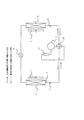
図4により、空気調和機200の冷凍サイクルの一例について説明する。冷凍サイクルは、例えば、冷媒を圧縮する圧縮機5、冷媒の流れる方向を切り替える四方弁10、室外(図示しない室外機)に設置される室外熱交換器6、高圧の液冷媒を低圧の二相冷媒に減圧する減圧装置9、室内(室内機)に設置される室内熱交換器3及び液冷媒を貯留するアキュムレータ11で構成される。
An example of the refrigeration cycle of the
図4における実線矢印は、冷房運転時の冷媒の流れる方向を示す。即ち、冷房運転時は、圧縮機5→四方弁10→室外熱交換器6→減圧装置9→室内熱交換器3→アキュムレータ11→圧縮機5の順に冷媒が流れる。
A solid line arrow in FIG. 4 indicates a direction in which the refrigerant flows during the cooling operation. That is, during the cooling operation, the refrigerant flows in the order of the
図4における破線矢印は、暖房運転時の冷媒の流れる方向を示す。即ち、暖房運転時は、圧縮機5→四方弁10→室内熱交換器3→減圧装置9→室外熱交換器6→アキュムレータ11→圧縮機5の順に冷媒が流れる。
The broken-line arrows in FIG. 4 indicate the direction in which the refrigerant flows during the heating operation. That is, during the heating operation, the refrigerant flows in the order of the
冷媒を圧縮する圧縮機5には、例えば、回転式圧縮機、スクロール圧縮機、往復式圧縮機等が使用される。但し、圧縮機5の種類は問わない。
For the
高圧の液冷媒を低圧の二相冷媒に減圧する減圧装置9には、例えば、電子式膨張弁が使用される。
For example, an electronic expansion valve is used for the
既に述べたように、室内熱交換器3には、室内熱交換器3の温度を検出する室内熱交換器温度センサー2が設けられる。
As already described, the
また、室内熱交換器3に送風を行う室内ファン1が設けられる。
Moreover, the
さらに、室内熱交換器3から若干離れた位置に、室内の空気温度を検出する室内空気温度センサー4が設けられる。
Further, an indoor air temperature sensor 4 for detecting the indoor air temperature is provided at a position slightly away from the
室外機(図示せず)の空気吸い込み口近傍に(室外熱交換器6からは離れた位置)に、室外の空気温度を検出する室外空気温度センサー8が設けられる。 An outdoor air temperature sensor 8 for detecting the outdoor air temperature is provided in the vicinity of the air suction port of the outdoor unit (not shown) (a position away from the outdoor heat exchanger 6).
また、室外熱交換器6に送風を行う室外ファン7が設けられる。
Moreover, the outdoor fan 7 which ventilates the
尚、図4に示す冷凍サイクルは、四方弁10を用いて冷房及び暖房運転が可能なものであるが、四方弁10を用いないものでもよい。
The refrigeration cycle shown in FIG. 4 can be cooled and heated using the four-
図5により、制御装置102について説明する。図5において、制御装置102内に内蔵されたマイクロコンピュータ(以下、マイコン)は、使用者が運転モードや設定温度、設定湿度、設定風速等(空気調和機の運転条件)の情報を設定するリモコン101(遠隔制御装置)からの情報を入力する入力部103と、各種の制御設定値やプログラムが記憶されているメモリ105と、演算処理や判断処理が行われるCPU104と、CPU104での演算結果や決定結果を出力する出力部106とから構成されている。尚、運転モードには、冷房運転モード、暖房運転モード、除湿運転モード、送風運転モード、空気清浄運転モード等がある。
The
入力部103には、少なくとも室内熱交換器温度センサー2、室内空気温度センサー4からの情報が入力される。
Information from at least the indoor heat
出力部106からは、少なくとも圧縮機5、室内ファン1へCPU104での演算結果や決定結果を出力する。
The
尚、ここでは使用者が空気調和機200の運転モードや運転条件を設定する装置を遠隔操作装置であるリモコン101としているが、リモコン101に限らず、設定を入力できるものであれば、使用者が設定する装置はリモコン101に限定されない(例えば、空気調和機200本体に備え付けられたスイッチなどでもよい)。
Here, the device for setting the operation mode and operation conditions of the
次に、本実施の形態の空気調和機200の制御装置102(マイコン)の機能について図6、図7を用いて説明する。空気調和機200は、冷房運転を行うものとする。
Next, the function of the control apparatus 102 (microcomputer) of the
以下で説明する各種動作及び手段は、空気調和機が備える制御装置102(マイコン)に組込まれたプログラムを実行することにより行われる。従って、動作の主語は制御装置102である。各動作において、一々「制御装置102が」という記載は省く場合が多い。
Various operations and means described below are performed by executing a program incorporated in the control device 102 (microcomputer) included in the air conditioner. Therefore, the subject of the operation is the
図6は空気調和機200の運転スイッチがONのときの圧縮機5及び室内ファン1の動作を示すタイムチャート図である。空気調和機200の運転スイッチは、遠隔操作装置であるリモコン101又は空気調和機200の本体に設けられる。
FIG. 6 is a time chart showing the operation of the
図7は室内ファン1の制御方法を示すフローチャート図である。
FIG. 7 is a flowchart showing a method for controlling the
時刻t1で空気調和機200の運転スイッチがON(S10)になると、続いて圧縮機5がONになり運転を開始する(S11)。
When the operation switch of the
圧縮機5がONになり、冷凍サイクルが動作を開始すると、室内熱交換器3は蒸発器としての動作を開始する。空気調和機200に吸い込まれる室内空気は、室内熱交換器3で冷却されて室内に吹き出されるので、室内空気温度センサー4が検出する室内空気温度は徐々に低下する。
When the
図6では室内空気温度センサー4が検出する室内空気温度の変化を実線で示し、室内熱交換器温度センサー2が検出する室内熱交換器温度の変化を破線で示している。
In FIG. 6, the change of the indoor air temperature detected by the indoor air temperature sensor 4 is indicated by a solid line, and the change of the indoor heat exchanger temperature detected by the indoor heat
図6において、A、B、Cは、夫々下記に示す時間である。
A:室内熱交換器3の熱影響を解消するための室内ファン1の運転時間;
B:圧縮機5の停止時における室内ファン1の停止時間;
C:正確な室温検知をするための室内ファン1の運転時間。
In FIG. 6, A, B, and C are the times shown below, respectively.
A: Operating time of the
B: Stop time of the
C: Operation time of the
空気調和機200を運転していない状態では、室内空気温度センサー4が検出する室内空気温度と室内熱交換器温度センサー2が検出する室内熱交換器温度とは、略等しい。
When the
圧縮機5がONすると、室内熱交換器3は蒸発器として動作するため、室内熱交換器3の温度は室内空気温度よりも温度の低下が大きく、室内空気温度センサー4が検出する室内空気温度が温調切り温度以下になる時点では、室内熱交換器3の温度は室内空気温度よりも数度以上低い。
When the
制御装置102は、室内空気温度センサー4が検出する室内空気温度を常に監視し、室内空気温度と温調切り温度とを比較している(S12)。温調切り温度は、リモコン等によりユーザが設定する設定温度に基づいて、制御装置102が予め決定しておく。例えば、冷房運転の場合は、リモコン等によりユーザが設定する設定温度より、1℃程度低い温度である。室内空気温度センサー4が検出する室温が、温調切り温度以下になると制御装置102は圧縮機5(冷凍サイクル)を停止する。
The
時刻t2で室内空気温度センサー4が検出する室温が、温調切り温度以下になると、圧縮機5を停止(OFF)し、室内ファン1は運転を継続する(S13)。
When the room temperature detected by the indoor air temperature sensor 4 at the time t2 becomes equal to or lower than the temperature regulation temperature, the
このときの室内ファン1の回転数は、リモコン101で設定できる最低の回転数とする。但し、制御装置102により、リモコン101で設定できる最低の回転数よりも低い回転数で室内ファン1が回転する運転モードが設定されていれば、リモコン101で設定できる最低の回転数でなく、その運転モードの回転数で回転させてもよい。
At this time, the rotation speed of the
すなわち、当該空気調和機200(室内機)において、制御装置102により室内ファン1に設定されている最低の回転数で室内ファン1を運転する。
That is, in the air conditioner 200 (indoor unit), the
圧縮機5が停止すると、蒸発器として動作していた室内熱交換器3の動作(冷媒の蒸発)が停止するため、室内ファン1により吸い込まれる室内空気(室内熱交換器3よりも温度が数度以上高い)により室内熱交換器3は温められる。そのため、室内熱交換器3の温度は、図6の破線で示すように、時刻t2から徐々に高くなる。
When the
制御装置102は、室内熱交換器温度センサー2が検出する室内熱交換器3の温度及び室内空気温度センサー4が検出する室温を常に監視し、両者を比較している(S14)。
The
時刻t3で、室内空気温度センサー4が検出する室内空気温度と、室内熱交換器温度センサー2が検出する室内熱交換器3の温度との温度差が、所定値(例えば、1℃)以下になったことを制御装置102が検出した場合は、室内ファン1を停止する(S15)。
At time t3, the temperature difference between the indoor air temperature detected by the indoor air temperature sensor 4 and the temperature of the
室内ファン1を、圧縮機5が停止してから時間Aだけ運転することになる。
The
室内ファン1を停止した後は、室内空気温度センサー4が検出する室内空気温度と、室内熱交換器温度センサー2が検出する室内熱交換器3の温度とは、略同じ温度で緩やかに上昇する。
After the
室内ファン1を停止した後も、制御装置102は室内空気温度センサー4が検出する室内空気温度を常に監視し、今度は温調入り温度と比較する(S17)。
Even after the
但し、本実施の形態では、室内空気温度センサー4が検出する室内空気温度が温調入り温度に到達する時刻t8の前の、例えば、時刻t4〜t5(時間C)、時刻t6〜t7(時間C)において所定時間室内ファン1を運転するようにしている。
However, in the present embodiment, for example, time t4 to t5 (time C), time t6 to t7 (time) before the time t8 when the indoor air temperature detected by the indoor air temperature sensor 4 reaches the temperature including the temperature adjustment. In C), the
即ち、時刻t3で室内ファン1を停止した後、定期的に室内ファン1を所定時間運転する(S16)。
That is, after the
これは、室内の空気温度を正確に室内空気温度センサー4で検出するためである。 This is because the indoor air temperature sensor 4 accurately detects the indoor air temperature.
室内の空気温度は、種々の要因により変動する。例えば、部屋のドア又は窓を開けることにより、外気が部屋に入り室内の空気温度は、上昇する。また、太陽の光があたる箇所は温度の上昇が他より早いため、室内の空気温度の分布に温度むらが生じる。 The indoor air temperature varies depending on various factors. For example, by opening a door or window in the room, outside air enters the room and the air temperature in the room rises. Moreover, since the temperature rises faster than others in the places where the sun is lit, the temperature distribution in the indoor air temperature is uneven.
時刻t3で室内ファン1を停止した後、定期的に室内ファン1を所定時間運転することにより、室内空気温度に変動があっても、正確に室内の空気温度を室内空気温度センサー4で検出することができる。
After the
圧縮機5の停止時における室内ファン1の停止時間B(時刻t3〜t4、時刻t5〜t6、時刻t7〜t8)は、およそ数分以下である。
The stop time B (time t3 to t4, time t5 to t6, time t7 to t8) of the
圧縮機5の停止時における室内ファン1の停止時間Bを、以下に示すような方法で決めてもよい。
The stop time B of the
即ち、室内空気温度センサー4が検出する室内空気温度と、室外空気温度センサー8が検出する室外空気温度との温度差が所定値より小さいときは、室内空気温度が大きく変動することがなく安定しているので、圧縮機5の停止時における室内ファン1の停止時間Bを所定値より長く設定する。
That is, when the temperature difference between the indoor air temperature detected by the indoor air temperature sensor 4 and the outdoor air temperature detected by the outdoor air temperature sensor 8 is smaller than a predetermined value, the indoor air temperature is not greatly changed and stabilized. Therefore, the stop time B of the
圧縮機5の停止時における室内ファン1の停止時間Bを所定値より長く設定することにより、正確に室内の空気温度を室内空気温度センサー4で検出するために、定期的に室内ファン1を所定時間運転する回数を減らすことができる。
In order to accurately detect the indoor air temperature with the indoor air temperature sensor 4 by setting the stop time B of the
それにより、さらに消費電力量を削減できる。 Thereby, the power consumption can be further reduced.
室内空気温度センサー4が検出する室内空気温度と、室外空気温度センサー8が検出する室外空気温度との温度差が所定値より大きいときは、室内空気温度が大きく変動することがあるので、圧縮機5の停止時における室内ファン1の停止時間Bを所定値より短く設定する。
When the temperature difference between the indoor air temperature detected by the indoor air temperature sensor 4 and the outdoor air temperature detected by the outdoor air temperature sensor 8 is larger than a predetermined value, the indoor air temperature may fluctuate greatly. The stop time B of the
圧縮機5の停止時における室内ファン1の停止時間Bを所定値より短く設定することにより、正確に室内の空気温度を室内空気温度センサー4で検出するために、定期的に室内ファン1を所定時間運転する回数を増やすことができる。
In order to accurately detect the indoor air temperature with the indoor air temperature sensor 4 by setting the stop time B of the
それにより、さらに正確に室内の空気温度を室内空気温度センサー4で検出することができ、ユーザに不快感を与える恐れが少ない室温の制御が可能となる。 Thereby, the indoor air temperature can be detected more accurately by the indoor air temperature sensor 4, and the room temperature can be controlled with less fear of giving the user unpleasant feeling.
以上、空気調和機200が冷房運転を行う場合につい説明したが、暖房運転を行う場合にも本実施の形態は有効である。
Although the case where the
以上のように、本実施の形態によれば、室内空気温度センサー4が検出する室温が、温調切り温度以下になると、圧縮機5を停止するが、室内ファン1は運転を継続する。そして、室内空気温度センサー4が検出する室内空気温度と、室内熱交換器温度センサー2が検出する室内熱交換器3の温度との温度差が、所定値以下になったことを制御装置102が検出した時点で、室内ファン1を停止するようにしたので、室温の制御に悪影響を及ぼすことなく、圧縮機5停止中の室内ファン1の運転時間を短縮して消費電力量を削減できる。
As described above, according to the present embodiment, when the room temperature detected by the indoor air temperature sensor 4 is equal to or lower than the temperature adjustment temperature, the
また、室内ファン1を停止した後、定期的に室内ファン1を所定時間運転することにより、室内空気温度に変動があっても、正確に室内の空気温度を室内空気温度センサー4で検出することができる。
In addition, after the
また、室内空気温度センサー4が検出する室内空気温度と、室外空気温度センサー8が検出する室外空気温度との温度差が所定値より小さいときは、圧縮機5の停止時における室内ファン1の停止時間Bを所定値より長く設定することにより、正確に室内の空気温度を室内空気温度センサー4で検出するために、定期的に室内ファン1を所定時間運転する回数を減らすことができ、さらに消費電力量を削減できる。
When the temperature difference between the indoor air temperature detected by the indoor air temperature sensor 4 and the outdoor air temperature detected by the outdoor air temperature sensor 8 is smaller than a predetermined value, the
また、室内空気温度センサー4が検出する室内空気温度と、室外空気温度センサー8が検出する室外空気温度との温度差が所定値より大きいときは、圧縮機5の停止時における室内ファン1の停止時間Bを所定値より短く設定することにより、正確に室内の空気温度を室内空気温度センサー4で検出するために、定期的に室内ファン1を所定時間運転する回数を増やすことができるので、さらに正確に室内の空気温度を室内空気温度センサー4で検出することができ、ユーザに不快感を与える恐れが少ない室温の制御が可能となる。
When the temperature difference between the indoor air temperature detected by the indoor air temperature sensor 4 and the outdoor air temperature detected by the outdoor air temperature sensor 8 is larger than a predetermined value, the
1 室内ファン、2 室内熱交換器温度センサー、3 室内熱交換器、3a 前面上部熱交換器、3b 前面下部熱交換器、3c 背面熱交換器、4 室内空気温度センサー、5 圧縮機、6 室外熱交換器、7 室外ファン、8 室外空気温度センサー、9 減圧装置、10 四方弁、11 アキュムレータ、21 吸込口、22 吹出口、23 前面パネル、24 ノズル、25 背面ガイド板、26 露受け部、27 露受け部、30 筐体、31 平板フィン、32 伝熱管、33 接続配管、40 小孔、101 リモコン、102 制御装置、103 入力部、104 CPU、105 メモリ、106 出力部、200 空気調和機。
DESCRIPTION OF
Claims (3)
前記室内側熱交換器に送風を行う室内ファンと、
前記室内側熱交換器の温度を検出する室内側熱交換器温度検出部と、
室内空気温度を検出する室内空気温度検出部と、
室外の空気温度を検出する室外空気温度センサーと、
前記室内空気温度検出部が検出する前記室内空気温度と、設定された設定温度とに基づいて、少なくとも前記圧縮機及び前記室内ファンの制御を行う制御装置と、を備え、
前記制御装置は、当該空気調和機の運転中に前記圧縮機を停止した場合、前記室内ファンの運転を継続し、前記室内側熱交換器温度検出部が検出する前記室内側熱交換器の温度と、前記室内空気温度検出部が検出する前記室内空気温度との温度差が所定値以下になった時点で前記室内ファンを停止し、
前記制御装置は、当該空気調和機の運転中に前記圧縮機を停止し、さらに前記室内ファンを停止した後、前記室内ファンを定期的に所定時間運転するとともに、前記室内空気温度検出部が検出する前記室内空気温度と前記室外空気温度センサーが検出する前記室外空気温度との温度差が所定温度差より小さいときは、前記圧縮機の停止時における前記室内ファンの停止時間を所定の停止時間より長く設定し、前記室内空気温度検出部が検出する前記室内空気温度と前記室外空気温度センサーが検出する前記室外空気温度との温度差が前記所定温度差より大きいときは、前記圧縮機の停止時における前記室内ファンの停止時間を前記所定の停止時間より短く設定することを特徴とする空気調和機。 A refrigeration cycle having a compressor that compresses at least the refrigerant, an outdoor heat exchanger that is provided outdoors, a decompression device that decompresses high-pressure liquid refrigerant into a low-pressure two-phase refrigerant, and an indoor heat exchanger that is provided indoors;
An indoor fan for blowing air to the indoor heat exchanger;
An indoor heat exchanger temperature detection unit for detecting the temperature of the indoor heat exchanger;
An indoor air temperature detector for detecting the indoor air temperature;
An outdoor air temperature sensor for detecting the outdoor air temperature;
A control device that controls at least the compressor and the indoor fan based on the indoor air temperature detected by the indoor air temperature detection unit and the set temperature that has been set,
When the compressor is stopped during the operation of the air conditioner, the control device continues the operation of the indoor fan and detects the temperature of the indoor heat exchanger detected by the indoor heat exchanger temperature detection unit. And when the temperature difference between the indoor air temperature detected by the indoor air temperature detection unit becomes a predetermined value or less, the indoor fan is stopped ,
The control device stops the compressor during operation of the air conditioner, and further stops the indoor fan, and then periodically operates the indoor fan for a predetermined time and is detected by the indoor air temperature detection unit. When the temperature difference between the indoor air temperature and the outdoor air temperature detected by the outdoor air temperature sensor is smaller than a predetermined temperature difference, the stop time of the indoor fan when the compressor is stopped is determined from the predetermined stop time. When the temperature difference between the indoor air temperature detected by the indoor air temperature detection unit and the outdoor air temperature detected by the outdoor air temperature sensor is larger than the predetermined temperature difference, the compressor is stopped. The air conditioner is characterized in that the indoor fan stop time is set shorter than the predetermined stop time .
前記室内側熱交換器に送風を行う室内ファンと、
前記室内側熱交換器の温度を検出する室内側熱交換器温度検出部と、
室内空気温度を検出する室内空気温度検出部と、
室外の空気温度を検出する室外空気温度センサーと、
前記室内空気温度検出部が検出する前記室内空気温度と、設定された設定温度とに基づいて、少なくとも前記圧縮機及び前記室内ファンの制御を行う制御装置と、を備え、
前記制御装置は、当該空気調和機の運転中に前記圧縮機を停止した場合、前記室内ファンの運転を継続し、前記室内側熱交換器温度検出部が検出する前記室内側熱交換器の温度と、前記室内空気温度検出部が検出する前記室内空気温度との温度差が所定値以下になった時点で前記室内ファンを停止し、
前記制御装置は、当該空気調和機の運転中に前記圧縮機を停止し、さらに前記室内ファンを停止した後、前記室内ファンを定期的に所定時間運転するとともに、前記室内空気温度検出部が検出する前記室内空気温度と前記室外空気温度センサーが検出する前記室外空気温度との温度差が所定温度差より小さいときは、前記圧縮機の停止時における前記室内ファンの停止時間を所定の停止時間より長く設定することを特徴とする空気調和機。 A refrigeration cycle having a compressor that compresses at least the refrigerant, an outdoor heat exchanger that is provided outdoors, a decompression device that decompresses high-pressure liquid refrigerant into a low-pressure two-phase refrigerant, and an indoor heat exchanger that is provided indoors;
An indoor fan for blowing air to the indoor heat exchanger;
An indoor heat exchanger temperature detection unit for detecting the temperature of the indoor heat exchanger;
An indoor air temperature detector for detecting the indoor air temperature;
An outdoor air temperature sensor for detecting the outdoor air temperature;
A control device that controls at least the compressor and the indoor fan based on the indoor air temperature detected by the indoor air temperature detection unit and the set temperature that has been set,
When the compressor is stopped during the operation of the air conditioner, the control device continues the operation of the indoor fan and detects the temperature of the indoor heat exchanger detected by the indoor heat exchanger temperature detection unit. And when the temperature difference between the indoor air temperature detected by the indoor air temperature detection unit becomes a predetermined value or less, the indoor fan is stopped ,
The control device stops the compressor during operation of the air conditioner, and further stops the indoor fan, and then periodically operates the indoor fan for a predetermined time and is detected by the indoor air temperature detection unit. When the temperature difference between the indoor air temperature and the outdoor air temperature detected by the outdoor air temperature sensor is smaller than a predetermined temperature difference, the stop time of the indoor fan when the compressor is stopped is determined from the predetermined stop time. An air conditioner characterized by a long setting .
前記室内側熱交換器に送風を行う室内ファンと、
前記室内側熱交換器の温度を検出する室内側熱交換器温度検出部と、
室内空気温度を検出する室内空気温度検出部と、
室外の空気温度を検出する室外空気温度センサーと、
前記室内空気温度検出部が検出する前記室内空気温度と、設定された設定温度とに基づいて、少なくとも前記圧縮機及び前記室内ファンの制御を行う制御装置と、を備え、
前記制御装置は、当該空気調和機の運転中に前記圧縮機を停止した場合、前記室内ファンの運転を継続し、前記室内側熱交換器温度検出部が検出する前記室内側熱交換器の温度と、前記室内空気温度検出部が検出する前記室内空気温度との温度差が所定値以下になった時点で前記室内ファンを停止し、
前記制御装置は、当該空気調和機の運転中に前記圧縮機を停止し、さらに前記室内ファンを停止した後、前記室内ファンを定期的に所定時間運転するとともに、前記室内空気温度検出部が検出する前記室内空気温度と前記室外空気温度センサーが検出する前記室外空気温度との温度差が所定温度差より大きいときは、前記圧縮機の停止時における前記室内ファンの停止時間を所定の停止時間より短く設定することを特徴とする空気調和機。 A refrigeration cycle having a compressor that compresses at least the refrigerant, an outdoor heat exchanger that is provided outdoors, a decompression device that decompresses high-pressure liquid refrigerant into a low-pressure two-phase refrigerant, and an indoor heat exchanger that is provided indoors;
An indoor fan for blowing air to the indoor heat exchanger;
An indoor heat exchanger temperature detection unit for detecting the temperature of the indoor heat exchanger;
An indoor air temperature detector for detecting the indoor air temperature;
An outdoor air temperature sensor for detecting the outdoor air temperature;
A control device that controls at least the compressor and the indoor fan based on the indoor air temperature detected by the indoor air temperature detection unit and the set temperature that has been set,
When the compressor is stopped during the operation of the air conditioner, the control device continues the operation of the indoor fan and detects the temperature of the indoor heat exchanger detected by the indoor heat exchanger temperature detection unit. And when the temperature difference between the indoor air temperature detected by the indoor air temperature detection unit becomes a predetermined value or less, the indoor fan is stopped ,
The control device stops the compressor during operation of the air conditioner, and further stops the indoor fan, and then periodically operates the indoor fan for a predetermined time and is detected by the indoor air temperature detection unit. When the temperature difference between the indoor air temperature detected and the outdoor air temperature detected by the outdoor air temperature sensor is larger than a predetermined temperature difference, the stop time of the indoor fan when the compressor is stopped is determined from the predetermined stop time. An air conditioner characterized by a short setting .
Priority Applications (1)
| Application Number | Priority Date | Filing Date | Title |
|---|---|---|---|
| JP2008320276A JP5042205B2 (en) | 2008-12-16 | 2008-12-16 | Air conditioner |
Applications Claiming Priority (1)
| Application Number | Priority Date | Filing Date | Title |
|---|---|---|---|
| JP2008320276A JP5042205B2 (en) | 2008-12-16 | 2008-12-16 | Air conditioner |
Publications (3)
| Publication Number | Publication Date |
|---|---|
| JP2010144958A JP2010144958A (en) | 2010-07-01 |
| JP2010144958A5 JP2010144958A5 (en) | 2010-08-26 |
| JP5042205B2 true JP5042205B2 (en) | 2012-10-03 |
Family
ID=42565571
Family Applications (1)
| Application Number | Title | Priority Date | Filing Date |
|---|---|---|---|
| JP2008320276A Active JP5042205B2 (en) | 2008-12-16 | 2008-12-16 | Air conditioner |
Country Status (1)
| Country | Link |
|---|---|
| JP (1) | JP5042205B2 (en) |
Families Citing this family (9)
| Publication number | Priority date | Publication date | Assignee | Title |
|---|---|---|---|---|
| US9664426B2 (en) * | 2012-08-20 | 2017-05-30 | Agile8 Consulting Limited | System and method for improving efficiency of a refrigerant based system |
| CN105042782B (en) * | 2015-07-24 | 2017-12-22 | 美的集团武汉制冷设备有限公司 | The control method and device of air conditioner |
| JP6494562B2 (en) * | 2016-04-27 | 2019-04-03 | 三菱電機株式会社 | Control device, air conditioning system, control method, and program |
| CN106196437A (en) * | 2016-07-06 | 2016-12-07 | 美的集团武汉制冷设备有限公司 | The control method of air-conditioner |
| CN107023935B (en) * | 2017-03-08 | 2019-10-25 | 广东美的制冷设备有限公司 | Air-conditioning system and its halt control method |
| WO2018207275A1 (en) * | 2017-05-10 | 2018-11-15 | 三菱電機株式会社 | Air conditioner and method for controlling operation of air conditioner |
| CN107339774A (en) * | 2017-06-13 | 2017-11-10 | 美的集团武汉制冷设备有限公司 | Control method, control device, air conditioner and computer-readable recording medium |
| CN110145837B (en) * | 2019-04-19 | 2020-11-27 | 青岛海尔空调器有限总公司 | Air conditioner and control method thereof |
| CN113091204B (en) * | 2021-03-12 | 2022-12-23 | 青岛海尔空调器有限总公司 | Method and device for controlling air conditioner and air conditioner |
Family Cites Families (8)
| Publication number | Priority date | Publication date | Assignee | Title |
|---|---|---|---|---|
| JPS57179034U (en) * | 1981-05-07 | 1982-11-12 | ||
| JPS5896935A (en) * | 1981-12-07 | 1983-06-09 | Sharp Corp | Control circuit for air conditioner |
| JPH0372761U (en) * | 1989-11-17 | 1991-07-23 | ||
| JPH05106906A (en) * | 1991-10-17 | 1993-04-27 | Hitachi Ltd | Controller of air conditioner |
| JP2002228233A (en) * | 2001-01-26 | 2002-08-14 | Matsushita Electric Ind Co Ltd | Air conditioner |
| JP2003254585A (en) * | 2002-02-28 | 2003-09-10 | Toshiba Kyaria Kk | Air conditioner |
| JP2005024111A (en) * | 2003-06-30 | 2005-01-27 | Matsushita Electric Ind Co Ltd | Multi-chamber type air conditioner |
| JP2005030670A (en) * | 2003-07-11 | 2005-02-03 | Matsushita Electric Ind Co Ltd | Air conditioner provided with refrigerant heating device |
-
2008
- 2008-12-16 JP JP2008320276A patent/JP5042205B2/en active Active
Also Published As
| Publication number | Publication date |
|---|---|
| JP2010144958A (en) | 2010-07-01 |
Similar Documents
| Publication | Publication Date | Title |
|---|---|---|
| JP5042205B2 (en) | Air conditioner | |
| JP5975937B2 (en) | Air conditioner | |
| JP2009097755A (en) | Air conditioner | |
| JP2008101894A (en) | Air conditioner and control method therefor | |
| JP7026781B2 (en) | Air conditioning system | |
| JP2008175490A (en) | Air conditioner | |
| JP5244411B2 (en) | Energy saving operation method of air conditioner and air conditioner | |
| WO2020053929A1 (en) | Air conditioning device | |
| JP6211892B2 (en) | Air conditioner | |
| KR100561136B1 (en) | Air conditioner | |
| JP5369577B2 (en) | Air conditioning system | |
| JP4548979B2 (en) | Air conditioner | |
| KR100307228B1 (en) | Power saving control method of air conditioner_ | |
| KR102429294B1 (en) | Control method of the inverter dehumidifier | |
| JP2006226584A (en) | Air conditioner | |
| JP2005016830A (en) | Air-conditioner | |
| KR100765169B1 (en) | Method for operating dehumidification temperature of air conditioner | |
| KR100784844B1 (en) | Apparatus for drying condensate in air conditioner | |
| JP4710352B2 (en) | Ventilator and air conditioner | |
| JP5797169B2 (en) | Air conditioner | |
| KR100393777B1 (en) | Dehumidifying operation control method for air conditioner | |
| JP2006317113A (en) | Indoor unit and air conditioner | |
| JP4090315B2 (en) | Air conditioner | |
| KR20120072850A (en) | Freezing protection method for evaporator | |
| JP6745895B2 (en) | Air conditioning system |
Legal Events
| Date | Code | Title | Description |
|---|---|---|---|
| A521 | Request for written amendment filed |
Free format text: JAPANESE INTERMEDIATE CODE: A523 Effective date: 20100712 |
|
| A621 | Written request for application examination |
Free format text: JAPANESE INTERMEDIATE CODE: A621 Effective date: 20100712 |
|
| A977 | Report on retrieval |
Free format text: JAPANESE INTERMEDIATE CODE: A971007 Effective date: 20111226 |
|
| A131 | Notification of reasons for refusal |
Free format text: JAPANESE INTERMEDIATE CODE: A131 Effective date: 20120110 |
|
| A521 | Request for written amendment filed |
Free format text: JAPANESE INTERMEDIATE CODE: A523 Effective date: 20120122 |
|
| TRDD | Decision of grant or rejection written | ||
| A01 | Written decision to grant a patent or to grant a registration (utility model) |
Free format text: JAPANESE INTERMEDIATE CODE: A01 Effective date: 20120612 |
|
| A01 | Written decision to grant a patent or to grant a registration (utility model) |
Free format text: JAPANESE INTERMEDIATE CODE: A01 |
|
| A61 | First payment of annual fees (during grant procedure) |
Free format text: JAPANESE INTERMEDIATE CODE: A61 Effective date: 20120710 |
|
| R150 | Certificate of patent or registration of utility model |
Ref document number: 5042205 Country of ref document: JP Free format text: JAPANESE INTERMEDIATE CODE: R150 Free format text: JAPANESE INTERMEDIATE CODE: R150 |
|
| FPAY | Renewal fee payment (event date is renewal date of database) |
Free format text: PAYMENT UNTIL: 20150720 Year of fee payment: 3 |
|
| R250 | Receipt of annual fees |
Free format text: JAPANESE INTERMEDIATE CODE: R250 |
|
| R250 | Receipt of annual fees |
Free format text: JAPANESE INTERMEDIATE CODE: R250 |
|
| R250 | Receipt of annual fees |
Free format text: JAPANESE INTERMEDIATE CODE: R250 |
|
| R250 | Receipt of annual fees |
Free format text: JAPANESE INTERMEDIATE CODE: R250 |
|
| R250 | Receipt of annual fees |
Free format text: JAPANESE INTERMEDIATE CODE: R250 |
|
| R250 | Receipt of annual fees |
Free format text: JAPANESE INTERMEDIATE CODE: R250 |
|
| R250 | Receipt of annual fees |
Free format text: JAPANESE INTERMEDIATE CODE: R250 |
|
| R250 | Receipt of annual fees |
Free format text: JAPANESE INTERMEDIATE CODE: R250 |
|
| R250 | Receipt of annual fees |
Free format text: JAPANESE INTERMEDIATE CODE: R250 |