JP5039582B2 - Electronics - Google Patents
Electronics Download PDFInfo
- Publication number
- JP5039582B2 JP5039582B2 JP2008011659A JP2008011659A JP5039582B2 JP 5039582 B2 JP5039582 B2 JP 5039582B2 JP 2008011659 A JP2008011659 A JP 2008011659A JP 2008011659 A JP2008011659 A JP 2008011659A JP 5039582 B2 JP5039582 B2 JP 5039582B2
- Authority
- JP
- Japan
- Prior art keywords
- dial
- click
- bearing
- convex
- convex portion
- Prior art date
- Legal status (The legal status is an assumption and is not a legal conclusion. Google has not performed a legal analysis and makes no representation as to the accuracy of the status listed.)
- Expired - Fee Related
Links
Images
Landscapes
- Camera Bodies And Camera Details Or Accessories (AREA)
- Rotary Switch, Piano Key Switch, And Lever Switch (AREA)
Description
本発明は、例えば、デジタルカメラ等の電子機器に関する。 The present invention relates to an electronic device such as a digital camera.
デジタルカメラを使用する際には、一般に、撮影モードに設定して被写体を撮影した後、再生モードに切替えて撮影した内容をLCD等の表示部に表示して確認する。また、撮影モードには、露出や合焦等の各種設定を自動設定するオート撮影モードや、使用者が好みに応じて自ら設定するマニュアル撮影モード、さらには特殊な撮影条件に適した設定を行うための各種の撮影モードがある。 When using a digital camera, in general, after setting a shooting mode and shooting a subject, the mode is switched to a playback mode and the shooting content is displayed on a display unit such as an LCD for confirmation. In addition, the shooting mode includes an auto shooting mode that automatically sets various settings such as exposure and focus, a manual shooting mode that is set by the user according to their preferences, and settings that are suitable for special shooting conditions. There are various shooting modes for.
そして、これらの複数のモードを切り替える手段としては、ダイヤルの回転操作により各種モードを切り替えるモード切替ダイヤルが操作性がよいことから多く用いられている。 As a means for switching these plural modes, a mode switching dial for switching various modes by rotating the dial is often used because of its good operability.
図8に、従来のデジタルカメラを背面側から見た図を示す(特許文献1)。このデジタルカメラは、カメラ本体101の前面側に不図示の撮影レンズが設けられ、背面側にLCD等の表示部103が設けられている。また、カメラ本体101の上面には、レリーズボタン104及びモード切替ダイヤル105が設けられている。
FIG. 8 shows a diagram of a conventional digital camera viewed from the back side (Patent Document 1). This digital camera is provided with a photographing lens (not shown) on the front side of the
カメラが撮影モードの場合は、例えば撮影レンズが収納位置から撮影位置まで突出し、レリーズボタン104を押して撮影した被写体画像が表示部103に随時表示され、再生モードの場合はメモリカード等に記録済みの被写体画像が表示部103に表示される。
When the camera is in the shooting mode, for example, the shooting lens protrudes from the storage position to the shooting position, and the subject image shot by pressing the
レリーズボタン104は、使用者がカメラ本体101を保持した状態で操作し易い位置に配置されている。使用者は、表示部103で被写体を確認しながら撮影画角を設定し、レリーズボタン104を押して被写体像を撮影する。
The
モード切替ダイヤル105は、外周部105aの一部がカメラ本体101の背面側に露出して、使用者が回転操作し易いようになっている。モード切替ダイヤル105には、各種モードのアイコンが表示されており、モード切替ダイヤル105を回転させて、任意のアイコンをカメラ本体101に設けた指標に合わせることで、そのアイコンに該当するモードに切り替えることができる。また、カメラ本体101には、指標にアイコンが合致する位置でモード切替ダイヤル105の回転を静止させるためのクリック機構が設けられている。
The
モード切替ダイヤル105(以下、ダイヤル105という)のクリック機構は、クリック板バネ方式と呼ばれるものである。このクリック機構は、例えば、図9に示すように、カメラ本体101のダイヤル取付部101a、接点取付部107、ダイヤルビス108、接点ブラシ109、接点取付ビス110、ダイヤル基板111を備える。
The click mechanism of the mode switching dial 105 (hereinafter referred to as dial 105) is called a click leaf spring system. For example, as shown in FIG. 9, the click mechanism includes a
ダイヤル取付部101aには、ダイヤル105のダイヤル軸105bを回転可能に支持する軸受部101bが設けられている。また、軸受部101bの周囲を囲むように板バネ取付部101cが設けられ、該板バネ取付部101cにクリック板バネ106が配置されている。クリック板バネ106は、帯状の板バネ材を略C字形状に曲げて形成されて、その周方向の中間部に径方向外側へ突出した凸部106aを有する。
The
ダイヤル105の内周部には、凹凸状のクリック部105cが設けられ、このクリック部105cには、ダイヤル105を回転させた場合に、所定の回転角度ごとにクリック板バネ106の凸部106aが弾性的に係合するようになっている。これにより、所定の回転角度ごとに、ダイヤル105の回転角度位置が保持される。
An
また、ダイヤル軸105bの先端にはビス穴105dが設けられ、このビス穴105dには、接点取付部107がカメラ本体101の内面側に当接するように設けられる。そして、接点取付部107のビス穴107aに、接点取付ビス110によって接点ブラシ109が取り付けられる。
A
接点ブラシ109は、ダイヤル基板111と当接するように設けられており、ダイヤル105を回転させた場合に、ダイヤル105のダイヤル軸105bを中心に接点取付部107と一体に回転する。
The
接点ブラシ109と当接するダイヤル基板111には、接点ブラシ109の回転軌道に対応する位置に、導電パターン111aが設けられている。この導電パターン111aは、複数の分割された円弧状のパターンを有し、この複数の分割された円弧状のパターンによって、ダイヤル105を回転させた場合に、所定の回転角度位置ごとに接点を切り替えることが可能となる。
The
クリック板バネ106は、前述したように、周方向の中間部に径方向外側に突出した凸部106aを有しており、凸部106aの両側には、先端部106b,106cに向けて略C字形状に曲げられた湾曲部106d,106eが配置されている(図10参照)。
As described above, the
ダイヤル取付部101aには、図11に示すように、軸受部101bからカメラ本体101の背面側に略T字状に延びる当接部101dが設けられている。また、ダイヤル取付部101aには、カメラ本体101の前面側の軸受部101bの周囲に、円弧状の一対のリブ101e,101fが円周方向に互いに離間して設けられている。
As shown in FIG. 11, the
そして、図11に示すように、クリック板バネ106の先端部106b,106cを当接部101dに当接させて、凸部106aを図11の下方向(カメラ本体101の背面側)に押しながらダイヤル取付部101aの一対のリブ101e,101f間に組み込む。
Then, as shown in FIG. 11, the
かかる該組み込み状態においては、クリック板バネ106の湾曲部106d,106eが湾曲して凸部106aを図11の上方向(カメラ本体101の前面側)へ押し戻す力が生じる。
In such an assembled state, the
この状態で、図12に示すように、ダイヤル105を組み込むと、凸部106aがダイヤル105の内周面のクリック部105cの凹部105eに係合すると共に、リブ101e,101fに挟まれた状態となる。これにより、ダイヤル105を静止させた状態で保持することができる。
In this state, as shown in FIG. 12, when the
そして、この状態で、図13に示すように、ダイヤル105を矢印方向(図13の反時計回り方向)へ回転させると、ダイヤル105のクリック板バネ106の凸部106aに当接する部分が凹部105eから凸部105fに遷移する。この遷移する間は、クリック板バネ106の凸部106aがさらに下方向(カメラ本体101の背面側)に押される。
In this state, as shown in FIG. 13, when the
したがって、クリック板バネ106の湾曲部106d,106eはさらに湾曲して凸部106aに対してより強い押し戻し力が生じ、これにより、ダイヤル105の回転を戻そうとする抵抗力が生じる。
Therefore, the
この抵抗力に抗してさらにダイヤル105を回転させると、ダイヤル105の凸部106aに当接する部分が凸部105fから凹部105gに遷移する間は、凸部106aの押し戻す力によってダイヤル105の回転を促進する力が生じる。この抵抗力と促進力とが切り替わる作用によって、ダイヤル105の回転時にクリック力を得ることができる。
When the
図14に、従来の他のモード切替ダイヤルのクリック機構を示す(特許文献2)。このクリック機構は、接点ブラシ205に複数のクリック穴205aを設け、ダイヤル取付部203の内側に凹部203aを設けて該凹部203aに鋼球204を配置している。
FIG. 14 shows another conventional click mechanism of the mode switching dial (Patent Document 2). In this click mechanism, a plurality of
そして、カメラ本体202の背面側上部に配置されるダイヤル201の回転により複数のクリック穴205aのいずれかが鋼球204に係合する作用によってクリック機能を持たせている。
A click function is provided by the action of one of the plurality of
このクリック機構は、図12及び図13に示すクリック機構のようにダイヤル内部に配置されるものではなく、接点ブラシ205でクリック機構を兼用している。従って、ダイヤル形状のサイズやデザインに自由度がある反面、ダイヤルを全周回転させることができない。また、クリック穴205aと鋼球204との係合でクリックトルクを得るため、トルクが弱く、クリックの振動による接点接触が不安定になる他、カメラ内部のブラシ外径が大きくなりやすい。
ところで、特に通常の小型デジタルカメラでは、撮影レンズを外圧や衝撃から保護すると同時に機器としてのコンパクト性を維持するため、非撮影時には撮影レンズをカメラ本体に沈胴して収納するものが多い。 By the way, in particular, in general small digital cameras, in order to protect the photographing lens from external pressure and impact and at the same time maintain the compactness as a device, the photographing lens is often retracted and stored in the camera body when not photographing.
このため、デジタルカメラを鞄類等に収納した場合等において、モードが切り替わって撮影レンズが収納位置から撮影位置まで突出して外圧を受け易い状態にならないように、モード切替ダイヤルの不用意な回転を避けることが必要である。 For this reason, when the digital camera is housed in a bag, etc., the mode switching dial is rotated inadvertently so that the mode is switched and the photographing lens does not protrude from the stowed position to the photographing position and is susceptible to external pressure. It is necessary to avoid it.
この場合、図12及び図13に示すクリック板バネ方式を採用したダイヤル105の方が、図14に示すダイヤル201に比べてダイヤルの回転トルクを適正に保つことができるので、不用意なダイヤルの回転を避けるうえで有利である。
In this case, the
しかし、図12及び図13に示す所謂クリック板バネ方式を採用したダイヤル105では、デジタルカメラの小型化に伴うダイヤルの小径化が難しい。
However, in the
即ち、ダイヤル105の小径化に応じてクリック板バネ106を薄肉化すると、前述した凸部106aの押し戻す力も弱まり、十分なクリック力が得られない。
That is, if the
一方、クリック板バネ106の板厚をそのままにしてダイヤル105を小径化すると、湾曲部106d,106eに過剰な曲げ応力が発生してバネ折れの原因となる。このバネ折れを回避するためにはダイヤル105のクリック部105cの凹凸差を減らす必要が生じ、クリック力が不安定になりやすい。
On the other hand, if the diameter of the
そこで、本発明は、ダイヤルを小径化しても十分且つ安定したクリック力を得ることができるようにして、ダイヤルの不用意な回転を回避することができる電子機器を提供することを目的とする。 Therefore, an object of the present invention is to provide an electronic device that can obtain a sufficient and stable click force even when the diameter of the dial is reduced, and can avoid inadvertent rotation of the dial.
上記目的を達成するために、本発明の電子機器は、内周部に凹凸状のクリック部を有するダイヤルと、該ダイヤルを回転可能に支持する軸受部と、該軸受部の周囲に取り付けられ、湾曲部、前記湾曲部から径方向外側に突出して前記クリック部に弾性的に係合する凸部、及び前記凸部と前記湾曲部との間に形成される曲げ部を有するバネ部材と、を備える電子機器において、前記軸受部の周囲に取り付けられた前記バネ部材の前記曲げ部に対向する前記軸受部の領域に、径方向の厚みを前記軸受部の周囲に取り付けられた前記バネ部材の前記湾曲部に対向する前記軸受部の領域における径方向の厚みよりも薄くした薄肉部を形成することを特徴とする。 In order to achieve the above object, an electronic device of the present invention is attached to a dial having an uneven click portion on an inner peripheral portion, a bearing portion that rotatably supports the dial, and the periphery of the bearing portion. A curved portion, a convex portion protruding radially outward from the curved portion and elastically engaging with the click portion, and a spring member having a bent portion formed between the convex portion and the curved portion. In the electronic device comprising, in the region of the bearing portion facing the bent portion of the spring member attached around the bearing portion, the radial thickness of the spring member attached around the bearing portion A thin portion that is thinner than a radial thickness in a region of the bearing portion facing the curved portion is formed .
本発明の電子機器によれば、ダイヤルを小径化しても十分且つ安定したクリックトルクを得ることができるので、ダイヤルの不用意な回転を回避することができる。 According to the electronic device of the present invention, a sufficient and stable click torque can be obtained even if the dial is reduced in diameter, so that inadvertent rotation of the dial can be avoided.
以下、本発明の実施形態を図面を参照して説明する。 Hereinafter, embodiments of the present invention will be described with reference to the drawings.
(第1の実施形態)
図1は本発明の第1の実施形態である電子機器の一例としてのデジタルカメラを説明するための図であり、(a)はデジタルカメラを前面側から見た外観斜視図、(b)はデジタルカメラを背面側から見た外観斜視図である。なお、本実施形態では、非撮影時にはカメラ本体内に撮影レンズを収納するタイプのデジタルカメラを例に採る。
(First embodiment)
1A and 1B are diagrams for explaining a digital camera as an example of an electronic apparatus according to a first embodiment of the present invention. FIG. 1A is an external perspective view of the digital camera viewed from the front side, and FIG. It is the external appearance perspective view which looked at the digital camera from the back side. In the present embodiment, a digital camera of a type in which a photographing lens is housed in the camera body when not photographing is taken as an example.
本実施形態のデジタルカメラは、カメラ本体1の前面側に撮影レンズ2及びグリップ部4が設けられ、カメラ本体1の背面側に表示部3、ズームレバー5及びモード切替ダイヤル7が設けられ、カメラ本体1の上面にはレリーズボタン6が設けられている。
The digital camera of this embodiment is provided with a
モード切替ダイヤル7により撮影モードが選択されると、撮影レンズ2が収納位置から撮影位置まで突出し、レリーズボタン6を押して撮影した被写体の画像が表示部3に随時表示される。また、モード切替ダイヤル7により再生モードが選択されると、メモリカード等に記録済みの被写体画像が表示部3に表示される。
When the photographing mode is selected by the
グリップ部4は、使用者が右手で保持した状態でズームレバー5、レリーズボタン6、モード切替ダイヤル7等を操作しやすい形状になっている。使用者は、グリップ部4を保持した状態で表示部3で被写体を確認しながらズームレバー5を操作して撮影画角を設定し、レリーズボタン6を押して被写体像を撮影することができる。
The grip portion 4 has a shape that allows the user to easily operate the
モード切替ダイヤル7は、カメラ本体1の背面側において、表示部3の右上に配置されている。また、モード切替ダイヤル7は、カメラ本体1を保持した右手の人差し指で回転操作し易いように外周部7aの一部がカメラ本体1の上面側に露出しており、また、露出部分以外の部位からは回転操作し難くなっている。
The
モード切替ダイヤル7には、図2に示すように、各種モードを表す複数のアイコン7bが印刷されており、任意のアイコン7bがカメラ本体1に設けた指標1aに合致する位置でモード切替ダイヤル7が静止するようになっている。モード切替ダイヤル7を回転させ、複数のアイコン7bのいずれかを指標1aに合わせることで、そのアイコンに該当するモードに切り替えることができる。
As shown in FIG. 2, a plurality of
次に、アイコン7bが指標1aに合致する位置でモード切替ダイヤル7の回転を静止させるためのクリック機構について説明する。
Next, a click mechanism for stopping the rotation of the
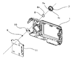
モード切替ダイヤル7(以下、ダイヤル7という)のクリック機構は、クリック板バネ方式を採用している。このクリック機構は、図2及び図3に示すように、カメラ本体1のダイヤル取付部1b、クリック板バネ8、ダイヤルビス9、接点ブラシ10、ダイヤル基板11を備える。
The click mechanism of the mode switching dial 7 (hereinafter referred to as dial 7) employs a click leaf spring system. As shown in FIGS. 2 and 3, the click mechanism includes a
ダイヤル取付部1bには、ダイヤル7のダイヤル軸7cを回転可能に支持する軸受部1cが設けられている。また、軸受部1cの周囲を囲むように板バネ取付部1dが設けられ、この板バネ取付部1dに、クリック板バネ(バネ部材)8が配置されている。クリック板バネ8は、帯状の板バネ材を略C字形状に曲げて形成されて、その周方向の中間部に径方向外側に突出した凸部8aを有する。
The
ダイヤル7の内周部には、凹凸状のクリック部7dが設けられ、このクリック部7dには、ダイヤル7を回転させた場合に、所定の回転角度ごとにクリック板バネ8の凸部8aが弾性的に係合するようになっている。これにより、所定の回転角度ごとに、ダイヤル7の回転角度位置が保持される。
An
また、ダイヤル軸7cの先端にはビス穴7eが設けられている。本実施形態では、ダイヤル軸7cの先端に接点ブラシ10がビス9によって直接取り付けられており、従来例で説明した接点取付部とダイヤルビスが省略されている。これにより、ダイヤル7の小径化を実現している。そして、接点ブラシ10は、ダイヤル基板11と当接するように設けられており、ダイヤル7を回転させた場合に、ダイヤル7のダイヤル軸7cを中心に回転する。
A
また、接点ブラシ10と当接するダイヤル基板11には、接点ブラシ10の回転軌道に対応する位置に、複数の分割された円弧状のパターンを有する導電パターン11aが設けられている。この導電パターン11aの複数の分割された円弧状のパターンによって、ダイヤル7を回転させた場合に、所定の回転角度位置ごとに接点を切り替えることが可能となる。
The
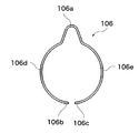
クリック板バネ8は、前述したように、周方向の中間部に径方向外側に突出した凸部8aを有しており、凸部8aの両側には、図4に示すように、先端部8b,8cに向けて略C字形状に曲げられた湾曲部8d,8eが形成されている。また、凸部8aと湾曲部8d,8eとの間には曲げ部8f,8gが形成されている。
As described above, the
ダイヤル取付部1bには、軸受部1cからカメラ本体1の下側に向けて略T字状に延びる当接部1gが設けられている。また、ダイヤル取付部1bには、カメラ本体1の上側を向く軸受部1cの周囲に、円弧状の一対のリブ1h,1iが円周方向に互いに離間して設けられている。
The
そして、クリック板バネ8を先端部8b,8cを当接部1gに当接させた状態で、凸部8aを図4の下方向(カメラ本体1の下側)に押しながらダイヤル取付部1bの一対のリブ1h,1i間に組み込む。
Then, with the
かかる組み込み状態においては、クリック板バネ8の湾曲部8d,8eが湾曲して凸部8aを図4の上方向(カメラ本体1の上側)に押し戻す力が生じる。
In such an assembled state, the
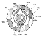
この状態で、ダイヤル7を軸受部1cに組み込むと、凸部8aがダイヤル7の内周面のクリック部7dに係合すると共に、リブ1h,1iに挟まれた状態となり、これにより、ダイヤル7を静止させた状態に保持することができる。リブ1h,1iはダイヤル7とクリック板バネ8の曲げ部8f,8gとの間に位置している。
In this state, when the
ここで、本実施形態では、軸受部1cは円筒状に形成されており、また、軸受部1cの外周面にはクリック板バネ8の曲げ部8f,8gと対向する領域に薄肉部1eが設けられている。これにより、ダイヤル7の小径化したことで、クリック板バネ8の収納空間が狭くなるのを回避している。また、薄肉部1eは、ダイヤル7の外周部7aがカメラ本体1の上面側に露出する方向と略一致する方向に配置されている。
Here, in the present embodiment, the bearing
また、軸受部1cの外周面であってクリック板バネ8の凸部8aに対向する部分には、該凸部8aに向けて突出する補強凸部1fが設けられている。この補強凸部1fの周方向の両側に、それぞれ前述した薄肉部1eが配置されている。補強凸部1fは、凸部8aに干渉しない範囲で薄肉部1e以外の領域における軸受部1cの直径よりも径方向外側に突出して、薄肉部1eによる軸受部1cの強度不足を補うようになっている。
A reinforcing
次に、ダイヤル7を回転操作した際のクリック機構の動作例について説明する。
Next, an operation example of the click mechanism when the
使用者は、カメラ本体1のグリップ部4を右手で保持し、人差し指でカメラ本体1の上面側に露出したダイヤル7の外周部7aを押圧しつつ外周部7aの接線方向に回してダイヤル7を図4の矢印方向に回転させる。
The user holds the grip part 4 of the
ダイヤル7を図4の矢印方向に回転させると、図5に示すように、ダイヤル7のクリック板バネ8の凸部8aに当接する部分が凹部7fから凸部7gに遷移する間に凸部8aがさらに下方向(カメラ本体1の下側)に押される。従って、クリック板バネ8の湾曲部8d,8eはさらに湾曲して凸部8aに対してより強い押し戻し力が生じ、これによりダイヤル7の回転を戻そうとする抵抗力が生じる。
When the
このとき、クリック板バネ8の凸部8aが下方向(カメラ本体1の下側)に押されて凸部8と湾曲部8d,8eとの間の曲げ部8f,8gが軸受部1cに接近する。しかし、本実施形態では、ダイヤル7を小径化しても、前述したように、軸受部1cに薄肉部1eを設けてクリック板バネ8の収納空間が狭くならないようにしている。
At this time, the
このため、クリック板バネ8の曲げ部8f,8gが軸受部1cに干渉するのを回避することができ、この結果、クリック板バネ8は必要な大きさを確保したままダイヤル取付部1bに収納することができる。
For this reason, it is possible to avoid the
続いて、さらにダイヤル7を回転させると、ダイヤル7の凸部8aに当接する部分が凸部7gから凹部7hに遷移する間は凸部8aの押し戻す力によってダイヤル7の回転を促進する力が生じる。この促進力と前述した抵抗力とが切り替わる作用によって、ダイヤル7の回転時にクリック力を得ることができる。
Subsequently, when the
以上説明したように、本実施形態では、軸受部1cの外周面にはクリック板バネ8の曲げ部8f,8gと対向する領域に薄肉部1eを設けているので、ダイヤル7を小径化しても、クリック板バネ8は必要な大きさを確保したままダイヤル取付部1bに収納することができる。
As described above, in the present embodiment, the
これにより、ダイヤル7を小径化しても十分且つ安定したクリック力を得ることができ、ダイヤル7の不用意な回転を回避することができる。
Thereby, even if the diameter of the
また、本実施形態では、薄肉部1eの凸部8aに対向する部分に補強凸部1fを設けて、薄肉部1eによる軸受部1cの強度不足を補強しているので、ダイヤル7が強い力で押されても、軸受部1cに対して十分な強度及び耐久性を確保することができる。
Moreover, in this embodiment, since the reinforcement
更に、本実施形態では、補強凸部1fを、凸部8aに干渉しない範囲で薄肉部1e以外の領域における軸受部1cの直径よりも径方向外側に突出させている。このため、凸部8aに干渉しない範囲を最大限利用して補強凸部1fが設けられることになるため、薄肉部1eによる軸受部1cの強度不足を確実に補強することができる。
Furthermore, in the present embodiment, the reinforcing
更に、本実施形態では、軸受部1cの薄肉部1eは、ダイヤル7の外周部7aがカメラ本体1の上面側に露出する方向、すなわち軸受部1cがダイヤル軸7cに押されない方向に配置されている。このため、ダイヤル7を回転させるときに外周部7aが押されても、薄肉部1eに押圧力が作用しないようにすることができる。
Furthermore, in the present embodiment, the
(第2の実施形態)
次に、図6及び図7を参照して、本発明の第2の実施形態である電子機器の一例としてのデジタルカメラを説明する。なお、上記第1の実施形態に対して重複又は相当する部分については、各図に同一符号を付してその説明を省略する。
(Second Embodiment)
Next, a digital camera as an example of an electronic apparatus according to the second embodiment of the present invention will be described with reference to FIGS. In addition, about the part which overlaps or corresponds to the said 1st Embodiment, the same code | symbol is attached | subjected to each figure and the description is abbreviate | omitted.
本実施形態では、軸受部1cの外周面にはクリック板バネ8の曲げ部8f,8gと対向する領域に欠肉部21eが設けられている。これにより、ダイヤル7の小径化したことでクリック板バネ8の収納空間が狭くなるのを回避している。この切欠き部21eは、ダイヤル7の外周部7aがカメラ本体1の上面側に露出する方向とほぼ同じ方向に配置されている。
In the present embodiment, a lacking
また、軸受部1cのクリック板バネの凸部8aに対向する部分には、該凸部8aに向けて突出する補強凸部21fが設けられており、この補強凸部21fの周方向両側に、それぞれ前述した切欠き部21eが配置されている。
Further, a reinforcing
この補強凸部21fは、凸部8aに干渉しない範囲で切欠き部21e以外の領域における軸受部1cの直径よりも径方向外側に突出して、切欠き部21eによる軸受部1cの強度不足を補うようになっている。
The reinforcing
次に、ダイヤル7を回転操作した際のクリック機構の動作例について説明する。
Next, an operation example of the click mechanism when the
使用者は、カメラ本体1のグリップ部4を右手で保持し、人差し指でカメラ本体1の上面側に露出したダイヤル7の外周部7aを押圧しつつ外周部7aの接線方向に回してダイヤル7を図6の矢印方向に回転させる。
The user holds the grip part 4 of the
ダイヤル7を図6の矢印方向に回転させると、図7に示すように、ダイヤル7のクリック板バネ8の凸部8aに当接する部分が凹部7fから凸部7gに遷移する間に凸部8aがさらに下方向(カメラ本体1の下側)に押される。従って、クリック板バネ8の湾曲部8d,8eはさらに湾曲して凸部8aに対してより強い押し戻し力が生じ、これによりダイヤル7の回転を戻そうとする抵抗力が生じる。
When the
このとき、クリック板バネ8の凸部8aが下方向(カメラ本体1の下側)に押されて凸部8と湾曲部8d,8eとの間の曲げ部8f,8gが軸受部1cに接近する。しかし、本実施形態では、ダイヤル7を小径化しても、前述したように、軸受部1cに切欠き部21eを設けてクリック板バネ8の収納空間が狭くならないようにしている。
At this time, the
このため、クリック板バネ8の曲げ部8f,8gが軸受部1cに干渉するのを回避することができ、この結果、クリック板バネ8は必要な大きさを確保したままダイヤル取付部1bに収納することができる。
For this reason, it is possible to avoid the
続いて、さらにダイヤル7を回転させると、ダイヤル7の凸部8aに当接する部分が凸部7gから凹部7hに遷移する間は凸部8aの押し戻す力によってダイヤル7の回転を促進する力が生じる。この促進力と前述した抵抗力とが切り替わる作用によって、ダイヤル7の回転時にクリック力を得ることができる。
Subsequently, when the
以上説明したように、本実施形態では、軸受部1cの外周面にはクリック板バネ8の曲げ部8f,8gと対向する領域に切欠き部21eを設けている。このため、ダイヤル7を上記第1の実施形態に比べて更に小径化しても、クリック板バネ8は必要な大きさを確保したままダイヤル取付部1bに収納することができる。
As described above, in the present embodiment, the
これにより、ダイヤル7をより小径化しても十分且つ安定したクリックトルクを得ることができ、ダイヤル7の不用意な回転を回避することができる。
Thereby, even if the diameter of the
また、本実施形態では、軸受部1cの凸部8aに対向する部分に補強凸部21fを設けて、切欠き部21eによる軸受部1cの強度不足を補強しているので、ダイヤル7が強い力で押されても、軸受部1cに対して十分な強度及び耐久性を確保することができる。
Moreover, in this embodiment, since the reinforcement
更に、本実施形態では、補強凸部21fを、凸部8aに干渉しない範囲で切欠き部21eを設けない状態での軸受部1cの直径よりも径方向外側に突出させている。このため、凸部8aに干渉しない範囲を最大限利用して補強凸部21fが設けられることになるため、切欠き部21eによる軸受部1cの強度不足を確実に補強することができる。
Further, in the present embodiment, the reinforcing
更に、本実施形態では、軸受部1cの切欠き部21eは、ダイヤル7の外周部7aがカメラ本体1の上面側に露出する方向、すなわち軸受部1cがダイヤル軸7cに押されない方向に配置されている。このため、ダイヤル7を回転させるときに外周部7aが押されても、切欠き部21eに押圧力が作用しないようにすることができる。
Furthermore, in this embodiment, the
なお、本発明は、上記各実施形態に例示したものに限定されるものではなく、本発明の要旨を逸脱しない範囲において適宜変更可能である。 In addition, this invention is not limited to what was illustrated by said each embodiment, In the range which does not deviate from the summary of this invention, it can change suitably.
例えば、上記各実施形態では、電子機器として、非撮影時にカメラ本体内に撮影レンズを収納するタイプのデジタルカメラを例示したが、これに限定されず、一眼レフタイプのカメラやその他の電子機器に本発明を適用してもよい。 For example, in each of the above embodiments, a digital camera of a type in which a photographing lens is housed in the camera body at the time of non-photographing is illustrated as an electronic device. The present invention may be applied.
また、上記各実施形態では、ダイヤル7をカメラ本体1の背面側に配置した場合を例示したが、これに限定されず、ダイヤル7をカメラ本体1の上面やその他の面に配置してもよい。
Further, in each of the above embodiments, the case where the
1 カメラ本体
1a 指標
1b ダイヤル取付部
1c 軸受部
1d 板バネ取付部
1e 薄肉部
1f 補強凸部
1g 当接部
1h,1・ リブ
2 撮影レンズ
3 表示部
4 グリップ部
5 ズームレバー
6 レリーズボタン
7 モード切替ダイヤル
7b アイコン
7c ダイヤル軸
7d クリック部
7e ビス穴
7f 凹部
7g 凸部
7h 凹部
8 クリック板バネ
8a 凸部
8b,8c 先端部
8d,8e 湾曲部
8f,8g 曲げ部
9 ダイヤルビス
10 接点ブラシ
11 ダイヤル基板
11a 導電パターン
21e 切欠き部
21f 補強凸部
DESCRIPTION OF
Claims (4)
該ダイヤルを回転可能に支持する軸受部と、
該軸受部の周囲に取り付けられ、湾曲部、前記湾曲部から径方向外側に突出して前記クリック部に弾性的に係合する凸部、及び前記凸部と前記湾曲部との間に形成される曲げ部を有するバネ部材と、を備える電子機器において、
前記軸受部の周囲に取り付けられた前記バネ部材の前記曲げ部に対向する前記軸受部の領域に、径方向の厚みを前記軸受部の周囲に取り付けられた前記バネ部材の前記湾曲部に対向する前記軸受部の領域における径方向の厚みよりも薄くした薄肉部を形成することを特徴とする電子機器。 A dial having an uneven click portion on the inner periphery,
A bearing that rotatably supports the dial;
A curved portion , a convex portion that protrudes radially outward from the curved portion and elastically engages with the click portion , and is formed between the convex portion and the curved portion. In an electronic device comprising a spring member having a bent portion,
In the region of the bearing portion that faces the bent portion of the spring member attached around the bearing portion , the radial thickness is opposed to the curved portion of the spring member attached around the bearing portion. an electronic device characterized by forming a thin Kushida thin portion than the thickness in the radial direction in the region of the bearing portion.
該ダイヤルを回転可能に支持する軸受部と、
該軸受部の周囲に取り付けられ、湾曲部、前記湾曲部から径方向外側に突出して前記クリック部に弾性的に係合する凸部、及び前記凸部と前記湾曲部との間に形成される曲げ部を有するバネ部材と、を備える電子機器において、
前記軸受部の周囲に取り付けられた前記バネ部材の前記曲げ部に対向する前記軸受部の領域に切欠き部を形成することを特徴とする電子機器。 A dial having an uneven click portion on the inner periphery,
A bearing that rotatably supports the dial;
A curved portion , a convex portion that protrudes radially outward from the curved portion and elastically engages with the click portion , and is formed between the convex portion and the curved portion. In an electronic device comprising a spring member having a bent portion,
An electronic device, wherein a notch portion is formed in a region of the bearing portion facing the bent portion of the spring member attached around the bearing portion.
Priority Applications (1)
| Application Number | Priority Date | Filing Date | Title |
|---|---|---|---|
| JP2008011659A JP5039582B2 (en) | 2008-01-22 | 2008-01-22 | Electronics |
Applications Claiming Priority (1)
| Application Number | Priority Date | Filing Date | Title |
|---|---|---|---|
| JP2008011659A JP5039582B2 (en) | 2008-01-22 | 2008-01-22 | Electronics |
Publications (3)
| Publication Number | Publication Date |
|---|---|
| JP2009176470A JP2009176470A (en) | 2009-08-06 |
| JP2009176470A5 JP2009176470A5 (en) | 2011-03-03 |
| JP5039582B2 true JP5039582B2 (en) | 2012-10-03 |
Family
ID=41031370
Family Applications (1)
| Application Number | Title | Priority Date | Filing Date |
|---|---|---|---|
| JP2008011659A Expired - Fee Related JP5039582B2 (en) | 2008-01-22 | 2008-01-22 | Electronics |
Country Status (1)
| Country | Link |
|---|---|
| JP (1) | JP5039582B2 (en) |
Cited By (1)
| Publication number | Priority date | Publication date | Assignee | Title |
|---|---|---|---|---|
| CN108935360A (en) * | 2017-05-18 | 2018-12-07 | 株式会社岛野 | double-bearing reel |
Families Citing this family (4)
| Publication number | Priority date | Publication date | Assignee | Title |
|---|---|---|---|---|
| JP5906845B2 (en) * | 2012-03-15 | 2016-04-20 | オムロン株式会社 | switch |
| JP7042040B2 (en) * | 2017-06-05 | 2022-03-25 | 株式会社シマノ | Double bearing reel |
| KR101897510B1 (en) * | 2017-09-12 | 2018-09-12 | 한국알프스 주식회사 | Rotary Type Switch Having Diffusion Structure For Light |
| JP2020198253A (en) | 2019-06-04 | 2020-12-10 | キヤノン株式会社 | Rotation operation device and electronic apparatus |
Family Cites Families (7)
| Publication number | Priority date | Publication date | Assignee | Title |
|---|---|---|---|---|
| JP4256112B2 (en) * | 2002-05-22 | 2009-04-22 | 株式会社ケンウッド | Rotation control knob structure of electronic equipment and electronic equipment |
| JP4449654B2 (en) * | 2004-08-25 | 2010-04-14 | ソニー株式会社 | Electronic device dialing device |
| JP2006208800A (en) * | 2005-01-28 | 2006-08-10 | Canon Inc | Electronic equipment |
| JP2007025113A (en) * | 2005-07-14 | 2007-02-01 | Canon Inc | Camera |
| JP2007025377A (en) * | 2005-07-19 | 2007-02-01 | Canon Inc | Dialing apparatus and electronic apparatus equipped with the same |
| JP2007299602A (en) * | 2006-04-28 | 2007-11-15 | Tokai Rika Co Ltd | Rotary switch device |
| JP5157158B2 (en) * | 2006-12-25 | 2013-03-06 | カシオ計算機株式会社 | Contact device |
-
2008
- 2008-01-22 JP JP2008011659A patent/JP5039582B2/en not_active Expired - Fee Related
Cited By (2)
| Publication number | Priority date | Publication date | Assignee | Title |
|---|---|---|---|---|
| CN108935360A (en) * | 2017-05-18 | 2018-12-07 | 株式会社岛野 | double-bearing reel |
| CN108935360B (en) * | 2017-05-18 | 2022-03-08 | 株式会社岛野 | Dual-bearing reel |
Also Published As
| Publication number | Publication date |
|---|---|
| JP2009176470A (en) | 2009-08-06 |
Similar Documents
| Publication | Publication Date | Title |
|---|---|---|
| JP3671883B2 (en) | Image recording / playback device | |
| JP5039582B2 (en) | Electronics | |
| EP2725417A1 (en) | Camera body, lens tube, and exchangeable-lens camera | |
| JP2007258198A (en) | Support structure of lid member and electronic equipment | |
| JP2019159149A (en) | Imaging apparatus | |
| JP5023454B2 (en) | Battery mounting mechanism and electronic equipment | |
| KR20130027255A (en) | Key assembly and rotary input device using the same | |
| JP2008205973A (en) | Imaging apparatus | |
| JP5725836B2 (en) | Electronics | |
| JP2007066571A (en) | Battery installation mechanism and electronic equipment | |
| US10969656B2 (en) | Electronic apparatus including movable display section | |
| JP5987565B2 (en) | Electronics | |
| JP6296894B2 (en) | Electronics | |
| JP2007257844A (en) | Push-button structure | |
| JP3938623B2 (en) | camera | |
| JP4207889B2 (en) | Operation unit structure | |
| JP4573077B2 (en) | Information processing device | |
| JP4679082B2 (en) | Lens drive device | |
| JP4829560B2 (en) | Operation input device, electronic device, and imaging device | |
| JP6225607B2 (en) | Dial with lock mechanism | |
| JP6016618B2 (en) | Electronics | |
| JP4948313B2 (en) | Electronics | |
| JP6833416B2 (en) | Electronics | |
| JP2013206662A (en) | Information setting device | |
| JP7146456B2 (en) | Rotating/swinging input device and electronic equipment |
Legal Events
| Date | Code | Title | Description |
|---|---|---|---|
| A521 | Written amendment |
Free format text: JAPANESE INTERMEDIATE CODE: A523 Effective date: 20110118 |
|
| A621 | Written request for application examination |
Free format text: JAPANESE INTERMEDIATE CODE: A621 Effective date: 20110118 |
|
| TRDD | Decision of grant or rejection written | ||
| A01 | Written decision to grant a patent or to grant a registration (utility model) |
Free format text: JAPANESE INTERMEDIATE CODE: A01 Effective date: 20120611 |
|
| A01 | Written decision to grant a patent or to grant a registration (utility model) |
Free format text: JAPANESE INTERMEDIATE CODE: A01 |
|
| A61 | First payment of annual fees (during grant procedure) |
Free format text: JAPANESE INTERMEDIATE CODE: A61 Effective date: 20120709 |
|
| FPAY | Renewal fee payment (event date is renewal date of database) |
Free format text: PAYMENT UNTIL: 20150713 Year of fee payment: 3 |
|
| R151 | Written notification of patent or utility model registration |
Ref document number: 5039582 Country of ref document: JP Free format text: JAPANESE INTERMEDIATE CODE: R151 |
|
| FPAY | Renewal fee payment (event date is renewal date of database) |
Free format text: PAYMENT UNTIL: 20150713 Year of fee payment: 3 |
|
| LAPS | Cancellation because of no payment of annual fees |


