JP5038843B2 - Method and device for transmitting signals in a wireless communication system by means of a special frame structure, and receiving device for receiving signals in a wireless communication system - Google Patents
Method and device for transmitting signals in a wireless communication system by means of a special frame structure, and receiving device for receiving signals in a wireless communication system Download PDFInfo
- Publication number
- JP5038843B2 JP5038843B2 JP2007263823A JP2007263823A JP5038843B2 JP 5038843 B2 JP5038843 B2 JP 5038843B2 JP 2007263823 A JP2007263823 A JP 2007263823A JP 2007263823 A JP2007263823 A JP 2007263823A JP 5038843 B2 JP5038843 B2 JP 5038843B2
- Authority
- JP
- Japan
- Prior art keywords
- preamble section
- preamble
- transmission
- frame
- frames
- Prior art date
- Legal status (The legal status is an assumption and is not a legal conclusion. Google has not performed a legal analysis and makes no representation as to the accuracy of the status listed.)
- Expired - Fee Related
Links
- 238000004891 communication Methods 0.000 title claims description 66
- 238000000034 method Methods 0.000 title claims description 19
- 230000005540 biological transmission Effects 0.000 claims description 167
- 238000011156 evaluation Methods 0.000 claims description 13
- 230000008054 signal transmission Effects 0.000 claims description 5
- 230000008859 change Effects 0.000 claims description 2
- 238000012549 training Methods 0.000 description 17
- 238000012545 processing Methods 0.000 description 9
- 238000010586 diagram Methods 0.000 description 8
- 244000062793 Sorghum vulgare Species 0.000 description 7
- 230000006870 function Effects 0.000 description 7
- 235000019713 millet Nutrition 0.000 description 7
- 238000011084 recovery Methods 0.000 description 4
- 238000010521 absorption reaction Methods 0.000 description 2
- 238000005516 engineering process Methods 0.000 description 2
- 238000005562 fading Methods 0.000 description 2
- 238000007476 Maximum Likelihood Methods 0.000 description 1
- 230000001133 acceleration Effects 0.000 description 1
- 230000010267 cellular communication Effects 0.000 description 1
- 230000000694 effects Effects 0.000 description 1
- 238000005259 measurement Methods 0.000 description 1
- 238000012986 modification Methods 0.000 description 1
- 230000004048 modification Effects 0.000 description 1
- 230000000737 periodic effect Effects 0.000 description 1
- 230000005855 radiation Effects 0.000 description 1
- 230000009467 reduction Effects 0.000 description 1
- 230000009466 transformation Effects 0.000 description 1
Images


Classifications
-
- H—ELECTRICITY
- H04—ELECTRIC COMMUNICATION TECHNIQUE
- H04B—TRANSMISSION
- H04B7/00—Radio transmission systems, i.e. using radiation field
- H04B7/02—Diversity systems; Multi-antenna system, i.e. transmission or reception using multiple antennas
- H04B7/04—Diversity systems; Multi-antenna system, i.e. transmission or reception using multiple antennas using two or more spaced independent antennas
- H04B7/06—Diversity systems; Multi-antenna system, i.e. transmission or reception using multiple antennas using two or more spaced independent antennas at the transmitting station
- H04B7/0686—Hybrid systems, i.e. switching and simultaneous transmission
- H04B7/0695—Hybrid systems, i.e. switching and simultaneous transmission using beam selection
-
- H—ELECTRICITY
- H04—ELECTRIC COMMUNICATION TECHNIQUE
- H04B—TRANSMISSION
- H04B7/00—Radio transmission systems, i.e. using radiation field
- H04B7/02—Diversity systems; Multi-antenna system, i.e. transmission or reception using multiple antennas
- H04B7/04—Diversity systems; Multi-antenna system, i.e. transmission or reception using multiple antennas using two or more spaced independent antennas
- H04B7/0408—Diversity systems; Multi-antenna system, i.e. transmission or reception using multiple antennas using two or more spaced independent antennas using two or more beams, i.e. beam diversity
-
- H—ELECTRICITY
- H04—ELECTRIC COMMUNICATION TECHNIQUE
- H04B—TRANSMISSION
- H04B7/00—Radio transmission systems, i.e. using radiation field
- H04B7/02—Diversity systems; Multi-antenna system, i.e. transmission or reception using multiple antennas
- H04B7/04—Diversity systems; Multi-antenna system, i.e. transmission or reception using multiple antennas using two or more spaced independent antennas
- H04B7/08—Diversity systems; Multi-antenna system, i.e. transmission or reception using multiple antennas using two or more spaced independent antennas at the receiving station
- H04B7/0868—Hybrid systems, i.e. switching and combining
- H04B7/088—Hybrid systems, i.e. switching and combining using beam selection
-
- H—ELECTRICITY
- H04—ELECTRIC COMMUNICATION TECHNIQUE
- H04B—TRANSMISSION
- H04B7/00—Radio transmission systems, i.e. using radiation field
- H04B7/02—Diversity systems; Multi-antenna system, i.e. transmission or reception using multiple antennas
- H04B7/04—Diversity systems; Multi-antenna system, i.e. transmission or reception using multiple antennas using two or more spaced independent antennas
- H04B7/08—Diversity systems; Multi-antenna system, i.e. transmission or reception using multiple antennas using two or more spaced independent antennas at the receiving station
- H04B7/0802—Diversity systems; Multi-antenna system, i.e. transmission or reception using multiple antennas using two or more spaced independent antennas at the receiving station using antenna selection
- H04B7/0805—Diversity systems; Multi-antenna system, i.e. transmission or reception using multiple antennas using two or more spaced independent antennas at the receiving station using antenna selection with single receiver and antenna switching
- H04B7/0808—Diversity systems; Multi-antenna system, i.e. transmission or reception using multiple antennas using two or more spaced independent antennas at the receiving station using antenna selection with single receiver and antenna switching comparing all antennas before reception
- H04B7/0811—Diversity systems; Multi-antenna system, i.e. transmission or reception using multiple antennas using two or more spaced independent antennas at the receiving station using antenna selection with single receiver and antenna switching comparing all antennas before reception during preamble or gap period
-
- H—ELECTRICITY
- H04—ELECTRIC COMMUNICATION TECHNIQUE
- H04W—WIRELESS COMMUNICATION NETWORKS
- H04W72/00—Local resource management
- H04W72/04—Wireless resource allocation
- H04W72/044—Wireless resource allocation based on the type of the allocated resource
- H04W72/046—Wireless resource allocation based on the type of the allocated resource the resource being in the space domain, e.g. beams
Description
本発明は、少なくとも1つのステアリング可能なビームアンテナを用いて信号を受信し、高速なデータレートの伝送を可能とする特別なフレーム構造によって、無線通信システム内で信号を受信する受信デバイスと、無線通信システム内で信号を伝送する方法とデバイスとに関する。 The present invention includes a receiving device receiving the signal using at least one steerable bi Muante Na, by a special frame structure which allows the transmission of high-speed data rates, for receiving signals in a wireless communication system, The present invention relates to a method and a device for transmitting a signal in a wireless communication system.
無線通信は、様々な技術分野で使用されており、携帯電話、無線LAN、トランシーバー、ブロードキャストラジオシステム、2地点間ラジオシステム、およびその他多くの既知の、あるいは未来のアプリケーションなどの例がある。それぞれの無線通信システムによってカバーされる半径は、基本的に、利用されている技術に依存する。GSMやUMTSシステムのようなセルラー方式(cellular communication system)は、約10Km(あるいはそれ以上)までの通信半径に適応するのに対し、無線LANは、約100m(あるいはそれ以上)の範囲、ブルートゥース(Bluetooth)システムでは数十m(あるいはそれ以上)の範囲に適応する。無線通信システムの通信範囲に大きく影響するのは、利用されている無線周波数と出力電力である。大気中では、GSMやUMTSに利用される無線周波数においては、電磁波の吸収はわずかしか起こらないが、低域および屋内無線通信に非常に適した60GHzにおいては、著しい吸収が起こる。さらに、それぞれの無線通信技術に利用される送受信アンテナの種類は、それぞれのアプリケーションの分野に依存して変わる。例えば、もし複数の受信者数に届ける必要がある場合か、または、もし受信者の位置が分からない、あるいは、例えば移動によって頻繁に変わる場合は、ワイドビームアンテナ(wide beam antenna)、または全方位アンテナ(omni−directional antenna)が、時々利用される。しかし、高速なデータレートのミリ波無線通信では、マルチパスフェージング効果(multi‐path fading effect)が原因で、ワイドビームアンテナの利用には問題がある。例えば、ワイドビームアンテナが、伝送者と受信者の両側で利用されており、直接見通し通信(LOS:line of sight)経路が、障害物、例えば移動している人間や車両のようなもの、によって妨害された場合、伝送者と受信者との間には、多数の反射経路が存在する。反射経路は、すなわち、伝送された電磁波が、受信者に届く前に少なくとも1回物体(object)によって反射された伝送経路である。データレートが高速である、例えば、1Gbpsを超える場合は、そのことが、重度の周波数選択性フェージングが原因となるサービスの符号間干渉を招き、チャネル遅延拡散(channel delay spread)は、数十のシンボル期間(symbol period)に渡る。 Wireless communication is used in various technical fields, such as mobile phones, wireless LANs, transceivers, broadcast radio systems, point-to-point radio systems, and many other known or future applications. The radius covered by each wireless communication system basically depends on the technology used. Cellular communication systems, such as GSM and UMTS systems, are adapted to communication radii up to about 10 km (or more), whereas wireless LANs have a range of about 100 m (or more), Bluetooth ( The Bluetooth system adapts to a range of several tens of meters (or more). The radio frequency and output power that are used greatly affect the communication range of the radio communication system. In the atmosphere, there is little absorption of electromagnetic waves at radio frequencies used for GSM and UMTS, but significant absorption occurs at 60 GHz, which is very suitable for low frequency and indoor radio communications. Furthermore, the type of transmission / reception antenna used for each wireless communication technology varies depending on the field of each application. For example, if it is necessary to reach multiple recipients, or if the recipient's location is unknown or changes frequently due to movement, for example, a wide beam antenna, or omnidirectional An antenna (omni-directional antenna) is sometimes used. However, in millimeter wave wireless communication at a high data rate, there is a problem in using a wide beam antenna due to a multi-path fading effect. For example, wide beam antennas are used on both the sender and receiver sides, and direct line-of-sight (LOS) paths are caused by obstacles, such as moving humans and vehicles. If disturbed, there are a number of reflection paths between the transmitter and the receiver. A reflection path is a transmission path in which a transmitted electromagnetic wave is reflected by an object at least once before reaching the recipient. When the data rate is high, for example, exceeding 1 Gbps, this leads to intersymbol interference of the service due to severe frequency selective fading, and the channel delay spread is several tens of Over a symbol period.
見通し外通信(NLOS:non line of sight)のような場合に対して、2つの従来解決方法が存在する。それら2つの解決方法は、両方とも、高速で複雑な信号処理回路を必要とする。1つの解決方法は、線形等化器または判定帰還形等化器または最尤系列推定(MLSE:maximum likelihood sequence estimation)等化器を含むチャネル等化器を採用している。チャネル遅延拡散が、符号の継続期間より非常に長ければ、等化器は複雑になり、多くの処理能力を必要とする。もう1つの解決方法は、直交周波数分割多重方式(OFDM:orthogonal frequency division multiplexing)技術であり、すでに無線LANシステムに採用されている。しかし、特有の直線変調と平均比に対する高いピークの問題が原因で、そのようなシステムの電力増幅器(PA:power amplifier)の電力消費量は非常に高い。1Gbpsの信号の復調には、明らかに、ハイスピードな高速フーリエ変換と他の信号処理モジュールとが必要とされる。それゆえ、高速なデータレートのミリ波領域通信システムに関して、複雑で高速なベースバンド電気回路を必要としない、他の解決方法を見つけることは重要である。 There are two conventional solutions for cases like non-line-of-sight (NLOS). Both of these two solutions require a fast and complex signal processing circuit. One solution employs a channel equalizer that includes a linear equalizer or decision feedback equalizer or a maximum likelihood sequence estimation (MLSE) equalizer. If the channel delay spread is much longer than the duration of the code, the equalizer becomes complex and requires a lot of processing power. Another solution is an orthogonal frequency division multiplexing (OFDM) technique, which has already been adopted in wireless LAN systems. However, due to the characteristic linear modulation and the high peak to average ratio problem, the power consumption of such system power amplifiers (PA) is very high. Clearly, the demodulation of a 1 Gbps signal requires a high-speed fast Fourier transform and other signal processing modules. Therefore, it is important to find other solutions that do not require complex and fast baseband electrical circuits for high data rate millimeter-wave communication systems.
上記の課題は、請求項1に記載の、無線通信システム内で信号を伝送する方法、請求項9に記載の、無線通信システム内で信号を伝送する伝送デバイス、および請求項17に記載の、無線通信システム内で信号を受信する受信デバイスによって解決される。
The above-mentioned problems are a method for transmitting a signal in a wireless communication system according to
本発明に従った方法は、無線通信システム内で信号を伝送する方法であり、本方法において、信号は、第1通信デバイスから第2通信デバイスに伝送され、前記信号は、連続したフレーム内で伝送され、それぞれのフレームは、プリアンブル情報を含むプリアンブルセクションを持っており、前記第1通信デバイス及び前記第2通信デバイスの少なくとも1つが、異なる位置にステアリングすることができるよう適応されたビームアンテナを持ち、それぞれの前記異なる位置が、前記第1通信デバイスから前記第2通信デバイスへの複数の異なる伝送経路の1つに対応しており、本方法は、前記ビームアンテナが、現在の伝送経路に対応する現在の位置にあるとき、現在の伝送経路のチャネル品質の評価を可能とするプリアンブル情報を含む第1プリアンブルセクションを送受信するステップと、前記ビームアンテナを、前記現在の位置から、候補伝送経路に対応する異なる位置にステアリングするステップと、前記ビームアンテナが、前記異なる位置にあるとき、前記候補伝送経路のチャネル品質の評価を可能とするプリアンブル情報を含む第2プリアンブルセクションを送受信するステップとを含む。 The method according to the present invention is a method for transmitting a signal in a wireless communication system, wherein the signal is transmitted from a first communication device to a second communication device, said signal being transmitted in consecutive frames. is transmitted, each frame having a preamble section comprising preamble information, before Symbol first communication device and the second communication device at least one, is adapted to be steered to different positions bi have Muantena, comprising respective front Kikoto position, the first corresponds to one of a plurality of different transmission paths from the communication device to the second communication device, the method, before millet Muantena is, when the current position corresponding to the current transmission path, comprising preamble information enabling the estimation of a channel quality of the current transmission path A method for transmitting and receiving 1 preamble section, a pre millet Muantena, from the position of the front Kigen standing, the steps of steered to different positions corresponding to the candidate transmission path, before millet Muantena is, when in the different positions and a step of transmitting and receiving a second preamble section comprising preamble information enabling the estimation of a channel quality of said candidate transmission path.
少なくともいくつかの前記フレームが、第1プリアンブルセクションと第2プリアンブルセクションとから構成されていることが好ましい。更に好適には、全てのフレームが、第1プリアンブルセクションと第2プリアンブルセクションとから構成されている。別の実施形態においては、前記第1プリアンブルセクションおよび前記第2プリアンブルセクションが、異なるフレーム内で伝送される。ここで、第1プリアンブルセクションから構成される伝送されるフレーム数に関して、第2プリアンブルセクションから構成される伝送されるフレーム数が、現在の伝送経路に関する、検出されたチャネル品質に依存して変更される。更に好適には、第1プリアンブルセクションから構成される伝送されるフレーム数に関して、第2プリアンブルセクションから構成される伝送されるフレーム数が、第1通信デバイス、および/または第2通信デバイスに関する、検出された移動情報に依存して変更される。更に好適には、第2プリアンブルセクションから構成されるそれぞれのフレームの後に、第1プリアンブルセクションから構成される標準的に伝送されるフレームに比べて長いフレーム長を持つ、第1プリアンブルセクションから構成されるフレームが伝送される。更に好適には、第1プリアンブルセクションと第2プリアンブルセクションが、互いに異なる。 Preferably, at least some of the frames are composed of a first preamble section and a second preamble section. More preferably, all the frames are composed of a first preamble section and a second preamble section. In another embodiment, the first preamble section and the second preamble section are transmitted in different frames. Here, with respect to the number of transmitted frames composed of the first preamble section, the number of transmitted frames composed of the second preamble section is changed depending on the detected channel quality with respect to the current transmission path. The More preferably, with respect to the number of transmitted frames composed of the first preamble section, the number of transmitted frames composed of the second preamble section is detected with respect to the first communication device and / or the second communication device. It is changed depending on the moved information. More preferably, each frame composed of the second preamble section is followed by a first preamble section having a longer frame length than a standard transmitted frame composed of the first preamble section. Frame is transmitted. More preferably, the first preamble section and the second preamble section are different from each other.
本発明に従った伝送デバイスは、無線通信システム内で信号を伝送する伝送デバイスであり、前記デバイスにおいて、前記信号が、連続したフレーム内で伝送され、それぞれのフレームは、プリアンブル情報を持つプリアンブルセクションを持っており、異なる位置にステアリングすることができるよう適応されたビームアンテナを含み、それぞれの前記異なる位置が、前記伝送デバイスから受信デバイスへの複数の異なる伝送経路の1つに対応しており、ステアリング手段は、前記アンテナを異なる位置にステアリングするように適応されており、プリアンブル発生手段は、プリアンブル情報を含むプリアンブルセクションを発生させるように適応されており、制御手段は、前記ビームアンテナが現在の伝送経路に対応する現在の位置にあるとき、前記現在の伝送経路のチャネル品質の評価を可能とするプリアンブル情報を含む第1プリアンブルセクションの伝送を制御するよう適応されており、さらに、前記ビームアンテナが候補伝送経路に対応する異なる位置にステアリングされた後に、前記候補伝送経路のチャネル品質の評価を可能とするプリアンブル情報を含む第2プリアンブルセクションの伝送を制御するよう適応されている。 A transmission device according to the present invention is a transmission device for transmitting a signal in a wireless communication system, wherein the signal is transmitted in consecutive frames, each frame having a preamble section having preamble information. the and have, include adapted bi Muantena to be steered to different positions, comprising respective front Kikoto position, corresponding to one of a number of different transmission paths from said transmitting device to the receiving device and the steering means, the antenna and the is adapted to steering the different positions, preamble generating means is adapted to generate a preamble section comprising preamble information, control means, before millet current position near the Muantena corresponding to transmission paths of the current When the being adapted to control the transmission of the first preamble section comprising preamble information enabling the estimation of a channel quality of the current transmission path, further, different pre millet Muantena correspond to candidate transmission paths After being steered to position, it is adapted to control the transmission of the second preamble section including preamble information that allows the channel quality of the candidate transmission path to be evaluated.
前記制御手段は、第1プリアンブルセクションおよび第2プリアンブルセクションから構成されている少なくともいくつかのフレームの伝送を制御するよう適応されていることが好ましい。更に好適には、前記制御手段が、全てのフレームが第1プリアンブルセクションおよび第2プリアンブルセクションから構成されている信号の伝送を制御するよう適応されている。別の実施形態においては、前記制御手段が、前記第1プリアンブルセクションおよび前記第2プリアンブルセクションが、異なるフレーム内で伝送される信号の伝送を制御するよう適応されている。ここで、前記制御手段が、第1プリアンブルセクションから構成されるフレーム数に関して、第2プリアンブルセクションから構成されるフレーム数を、現在の伝送経路に関して検出されたチャネル品質に依存して変更するように適応されていることが好ましい。更に好適には、前記制御手段が、第1プリアンブルセクションから構成される伝送されるフレーム数に関して、第2プリアンブルセクションから構成される伝送されるフレーム数を、伝送デバイス、および/または受信デバイスに関して検出された移動情報に依存して変更するように適応されている。ここで、前記制御手段が、第2プリアンブルセクションから構成されるそれぞれのフレームの後に、第1プリアンブルセクションから構成される標準的に伝送されるフレームに比べて長いフレーム長を持つ、第1プリアンブルセクションから構成されるフレームが伝送されるように、信号の伝送を制御するように適応されていることが好ましい。第1プリアンブルセクションと第2プリアンブルセクションは、互いに異なることが好ましい。 The control means is preferably adapted to control transmission of at least some frames composed of a first preamble section and a second preamble section. More preferably, the control means is adapted to control transmission of a signal in which every frame consists of a first preamble section and a second preamble section. In another embodiment, the control means is adapted to control transmission of signals transmitted by the first preamble section and the second preamble section in different frames. Here, the control means changes the number of frames composed of the second preamble section with respect to the number of frames composed of the first preamble section depending on the detected channel quality with respect to the current transmission path. It is preferably adapted. More preferably, the control means detects the number of transmitted frames composed of the second preamble section with respect to the number of transmitted frames composed of the first preamble section, with respect to the transmitting device and / or the receiving device. It is adapted to change depending on the movement information. Here, the control means has a first preamble section having a long frame length after each frame composed of the second preamble section as compared with a standard transmitted frame composed of the first preamble section. Is preferably adapted to control the transmission of signals such that a frame composed of The first preamble section and the second preamble section are preferably different from each other.
本発明に従った受信デバイスは、無線通信システム内で信号を受信する受信デバイスであり、前記デバイスにおいて、前記信号が、連続したフレーム内で送受信され、それぞれのフレームは、プリアンブル情報を持つプリアンブルセクションを持っており、異なる位置にステアリングすることができるよう適応されたビームアンテナを含み、それぞれの前記異なる位置が、伝送デバイスから受信デバイスへの複数の異なる伝送経路の1つに対応しており、ステアリング手段は、前記アンテナを異なる位置にステアリングするように適応されており、チャネル評価手段は、受信されたプリアンブル情報に基づいてチャネル品質を評価するよう適応されており、制御手段は、前記ビームアンテナが現在の伝送経路に対応する現在の位置にあるとき、前記現在の伝送経路のチャネル品質の評価を可能とするプリアンブル情報を含む第1プリアンブルセクションの受信を制御するよう適応されており、さらに、前記ビームアンテナが候補伝送経路に対応する異なる位置にステアリングされた後に、前記候補伝送経路のチャネル品質の評価を可能とするプリアンブル情報を含む第2プリアンブルセクションの受信を制御するよう適応されている。 A receiving device according to the present invention is a receiving device for receiving a signal in a wireless communication system, in which the signal is transmitted and received in successive frames, each frame having a preamble section having preamble information. the and have, include adapted bi Muantena to be steered to different positions, comprising respective front Kikoto position, corresponding to one of a plurality of different transmission paths from the transmitting device to the receiving device The steering means is adapted to steer the antenna to a different position, the channel evaluation means is adapted to evaluate the channel quality based on the received preamble information, and the control means when millet Muantena is located in the current position corresponding to the transmission path of the current Are adapted to control the reception of the first preamble section comprising preamble information enabling the estimation of a channel quality of the current transmission path, further, a different position before millet Muantena correspond to candidate transmission paths After being steered, it is adapted to control the reception of a second preamble section including preamble information that enables an evaluation of the channel quality of the candidate transmission path.
前記制御手段は、第1プリアンブルセクションおよび第2プリアンブルセクションから構成されている少なくともいくつかのフレームの受信を制御するよう適応されていることが好ましい。ここで、前記制御手段は、全てのフレームが第1プリアンブルセクションおよび第2プリアンブルセクションから構成されている信号の受信を制御するよう適応されていることが好ましい。別の実施形態においては、前記制御手段が、前記第1プリアンブルセクションおよび前記第2プリアンブルセクションが、異なるフレーム内で伝送される信号の受信を制御するよう適応されていることが好ましい。ここで、前記制御手段が、第1プリアンブルセクションから構成されるフレーム数に関して、第2プリアンブルセクションから構成されるフレーム数が、現在の伝送経路に関して検出されたチャネル品質に依存して変更される信号の受信を制御するよう適応されていることが好ましい。ここで、前記制御手段が、第1プリアンブルセクションから構成される伝送されるフレーム数に関して、第2プリアンブルセクションから構成される伝送されるフレーム数が、第1通信デバイス、および/または第2通信デバイスに関して検出された移動情報に依存して変更される信号の受信を制御するよう適応されていることが好ましい。更に好適には、前記制御手段が、第2プリアンブルセクションから構成されるそれぞれのフレームの後に、第1プリアンブルセクションから構成される標準的に伝送されるフレームに比べて長いフレーム長を持つ、第1プリアンブルセクションから構成されるフレームが受信されるように、信号の受信を制御するように適応されている。更に好適には、制御手段が、互いに異なる第1プリアンブルセクションと第2プリアンブルセクションの受信を制御するように適応されている。 The control means is preferably adapted to control reception of at least some frames composed of a first preamble section and a second preamble section. Here, it is preferable that the control means is adapted to control reception of a signal in which all frames are composed of a first preamble section and a second preamble section. In another embodiment, the control means is preferably adapted so that the first preamble section and the second preamble section control the reception of signals transmitted in different frames. Here, with respect to the number of frames composed of the first preamble section, the control means changes the number of frames composed of the second preamble section depending on the channel quality detected for the current transmission path. Is preferably adapted to control the reception of. Here, with respect to the number of frames transmitted from the first preamble section, the control means determines whether the number of frames transmitted from the second preamble section is the first communication device and / or the second communication device. Is preferably adapted to control the reception of signals that are modified depending on the detected movement information. More preferably, the control means has a long frame length after each frame composed of the second preamble section compared to a standard transmitted frame composed of the first preamble section. It is adapted to control the reception of signals so that a frame composed of preamble sections is received. More preferably, the control means is adapted to control the reception of different first and second preamble sections.
それゆえ、本発明は、複雑で高速な処理を必要としない、ミリ波長領域における高速なデータレートの無線通信に関する解決方法を提供する。特に、伝送データレートが高速であるとき、例えば1Gbpsあるいはそれ以上の領域において、フレーム誤り率(FER:frame error rate)の性能を同等のビット誤り率(BER:bit error rate)より低く保つために、フレーム長は短縮される。フレーム長が短くなる程、例えばプリアンブル情報の様な、ビームステアリングアルゴリズムに必要なオーバーヘッドは大きくなる。本発明は、異なるタイプのフレームの定義を含む新しいフレーム構造と、ビームアンテナのステアリングと高速なデータレートの両方を持つ無線データ通信を可能とするための、このような新しいタイプのフレームの組み合わせ方とを定義することによって、このオーバーヘッドを減らすことを可能とする。このような本発明の明確な利点は、ビームステアリングのために付加されるオーバーヘッドが少ないことと、フレーム誤り率の性能を同等のビット誤り率より低くなるよう改善するために、高速なデータレートの無線通信システムに関してフレーム長を短縮できることと、ビームステアリングの速度を動的に変化させ、増大することができることである。 Therefore, the present invention provides a solution for wireless communication at high data rates in the millimeter wavelength region that does not require complex and high speed processing. In particular, when the transmission data rate is high, for example, in order to keep the performance of the frame error rate (FER) lower than the equivalent bit error rate (BER) in the region of 1 Gbps or more. The frame length is shortened. The shorter the frame length, the greater the overhead required for the beam steering algorithm, such as preamble information. The present invention is different from the new frame structure including the definition of the type of frame, for enabling wireless data communication with both steering and fast data rate bi Muantena, how to combine these new types of frames This overhead can be reduced. The obvious advantages of the present invention are that there is less overhead added for beam steering, and that faster data rate is improved in order to improve the performance of the frame error rate to be lower than the equivalent bit error rate. The frame length can be shortened with respect to the wireless communication system, and the beam steering speed can be dynamically changed and increased.
以下に添付図面を参照しながら、本発明の好適な実施の形態について詳細に説明する。なお、本明細書及び図面において、実質的に同一の機能構成を有する構成要素については、同一の符号を付することにより重複説明を省略する。 Exemplary embodiments of the present invention will be described below in detail with reference to the accompanying drawings. In addition, in this specification and drawing, about the component which has the substantially same function structure, duplication description is abbreviate | omitted by attaching | subjecting the same code | symbol.
本発明は、あらゆる種類の領域上で信号を伝送および受信することが可能な、あらゆる種類の無線通信システムに適応することができる点に注意すべきである。さらに、本発明は、いかなる種類の変調方式や無線通信の技術的実装にも限定されない。しかし、本発明のいくつかの実施形態と実装は、例えば60Ghzの伝送領域のようなミリ波領域内で信号が伝送される、短距離および/または中距離無線通信システム内で利点がある。さらに、本発明の伝送デバイスおよび受信デバイスは、無線通信システム内で信号をそれぞれ伝送および受信するよう適応されたあらゆる種類のデバイスでありうる。“伝送デバイス”および“受信デバイス”という用語は、ここでは、移動できる、および/または固定されたあらゆる種類の通信装置、通信ユニット、通信手段、通信システムなどから構成されていることを意味している。本発明に従えば、伝送デバイスから受信デバイスに伝送される信号は、あらゆる理由と有効性のために伝送者から受信者に伝送される、あらゆる種類の情報、データ、符号などから構成されている。本発明によれば、伝送デバイスおよび受信デバイスの少なくとも1つは、異なる位置にステアリングされるよう適応されたビームアンテナを含む。いくつかの実装では、伝送デバイスと受信デバイスのそれぞれが、異なる位置にステアリングされるよう適応されたナロービームアンテナを含むことが好適である場合がある。“ナロービームアンテナ”という用語は、ここでは、特定の送受信方向を持たない全方位アンテナと逆で、特定のアンテナビームの形に限定されず、特定の送受信方向を持つあらゆる種類のアンテナで構成され、カバーされていることを意味している。さらに、本発明のナロービームアンテナは、どのような特定のステアリングタイプにも限定されない。特定のステアリングタイプとは、例えば、ナロービームアンテナの送受信方向が変更されたり、スイッチされたり、変化したりすると、異なる送受信位置にナロービームアンテナをステアリングまたはスイッチングすることを可能とする特定の技術的実装である。後述の例には限定されないが、例えば、本発明に従ったナロービームアンテナは、ビームの方向が変化したため、機械的に、あるいは電気的にアンテナをシフトすることによって変化させることが可能な、固定ナロービーム放射パターン(fixed narrow beam radiation pattern)を伴うアンテナである場合がある。さらに、ナロービームアンテナは、ビームの方向が変化したため、アンテナの位相および/または利得(gain)を変化させることによってステアリングされるタイプのアンテナであることもある。さらに別の場合は、ナロービームアンテナは、アンテナパターンのそれぞれのアンテナ要素が特定のナロービームアンテナ方向を持っており、その要素が、アンテナのビーム方向が変更されるという方法によって制御されることが可能であるアンテナパターンを含む。ステアリング可能なナロービームアンテナについての、現在知られている、あるいは将来的に開発される、他の多くの例があるが、それらは、本発明の技術的な範囲内に含まれるものである。
It should be noted that the present invention can be applied to any kind of wireless communication system capable of transmitting and receiving signals over any kind of region. Further, the present invention is not limited to any kind of modulation scheme or technical implementation of wireless communication. However, some embodiments and implementations of the present invention are advantageous in short-range and / or medium-range wireless communication systems where signals are transmitted in the millimeter wave region, such as the 60 Ghz transmission region. Furthermore, the transmission device and the reception device of the present invention can be any kind of device adapted to transmit and receive signals respectively in a wireless communication system. The terms “transmission device” and “reception device” here mean that it is composed of any kind of mobile and / or fixed communication device, communication unit, communication means, communication system, etc. Yes. According to the present invention, the signal transmitted from the transmission device to the receiving device is composed of all kinds of information, data, codes, etc. transmitted from the transmitter to the receiver for all reasons and effectiveness. . According to the present invention, at least one of the transmitting device and the receiving device includes adapted bi Muantena to be steered to different positions. In some implementations, it may be preferred that each of the transmitting device and the receiving device include a narrow beam antenna adapted to be steered to a different position. The term “narrow beam antenna” is used herein to refer to an omnidirectional antenna that does not have a specific transmission / reception direction, and is not limited to a specific antenna beam shape, but includes any type of antenna that has a specific transmission / reception direction. , That means being covered. Further, the narrow beam antenna of the present invention is not limited to any specific steering type. A specific steering type is a specific technical type that, for example, allows the narrow beam antenna to be steered or switched to different transmit / receive positions when the transmit / receive direction of the narrow beam antenna is changed, switched or changed. Implementation. Although not limited to the examples described below, for example, the narrow beam antenna according to the present invention is fixed, which can be changed by mechanically or electrically shifting the antenna because the beam direction has changed. It may be an antenna with a narrow beam radiation pattern. Further, the narrow beam antenna, since the direction of the beam is changed, sometimes the type of antenna to be steered by changing the antenna phase and / or gain (gain). In yet another case, a narrow beam antenna may be controlled by a method in which each antenna element of the antenna pattern has a specific narrow beam antenna direction, and the beam direction of the antenna is changed. Includes antenna patterns that are possible. There are many other examples of steerable narrow beam antennas that are currently known or that will be developed in the future, and are within the scope of the present invention.
本発明は、添付図面に関する以下の好適な実施形態の記述においてさらに詳細に説明される。 The invention is explained in more detail in the following description of preferred embodiments with reference to the accompanying drawings.
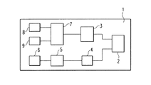
図1は、本発明に従って無線通信システム内で信号を伝送する伝送デバイスの概略的なブロック図を示している。ここでは、図1に示された、本発明の一実施形態の伝送デバイス1は、本発明の理解と実装のために必要な要素のみが表示されている。伝送デバイス1が無線通信システム内で信号を伝送することを可能とするために必要な、他の全ての要素は、明確化の目的で示されていない。しかし、実用的な実装においては、全てのそのような必要な要素が実装される。
FIG. 1 shows a schematic block diagram of a transmission device for transmitting signals in a wireless communication system according to the present invention. Here, the
伝送デバイス1は、アンテナステアリング手段4の制御のもと、異なる位置にステアリングされるよう適応したナロービームアンテナ2から構成される。ここで、アンテナステアリング手段4自体は、制御手段5によって制御される。制御手段5は、伝送デバイス1または他のあらゆる適切な制御ユニットのベースバンド処理および/または制御手段でありうる。制御手段5は、データや情報やアプリケーションやソフトウェアコードなどを格納するメモリ6に接続されている。
The
伝送デバイス1は、連続した時間フレーム内で信号を伝送するよう適応されており、そこでは、それぞれのフレームは、プリアンブル情報から構成されるプリアンブルセクションを持つ。そのようなフレームの例は、図4と図5と図8とに示されている。伝送デバイス1によって伝送される複数の連続した時間フレームの例は、図6と図7と図9に示されている。ここでは、“連続した”という用語は、フレームが次々に直接接して伝送されることを必ずしも意味するのではないことを理解すべきである。いくつかの実装では、2つの連続したフレーム間には、間隔Tgが存在する。間隔Tgは、例えば、無線ハイビジョンやそれと同様なもののように、長時間にわたり高速なデータレートの無線通信を維持するために、伝送デバイス1と、図2で示され、説明される受信デバイス10のような受信側との間のクロック差異(clock difference)を処理するために利用される。以下の記述と説明においては、2つの連続した時間フレーム間の間隔Tgは、ゼロと考えられている。図4に示される、本発明に従ったフレーム構造の第1実施形態においては、図4に示されているようなフレームは、Tfの長さを持ち、プリアンブルセクションとデータセクションとから構成されている。プリアンブルセクションは、伝送デバイス1のプリアンブルセクションジェネレータ9によって発生させられ、そこでは、プリアンブルの発生は、周波数領域処理または時間領域処理のどちらにおいても起こる。さらに、プリアンブルセクションジェネレータ9によって発生させられたプリアンブルは、要求された実装に依存して異なる長さとサイズとを持つ。フレームは、フレームジェネレータ7によって形成され、フレームジェネレータ7は、プリアンブルセクションジェネレータ9からプリアンブルセクションを取得し、データ手段8からデータを取得する。データ手段8は、あらゆる適切な方法でデータを発生し、収集し、取得し、フレームジェネレータ7にエータを転送する。フレームジェネレータ7によってフレームが発生された後で、発生されたフレームは、さらに通常の手段で、例えばフレーム情報などを変調することによって処理され、その後で高周波数に変換され、ナロービームアンテナ2を通して高周波数手段3を経由して伝送される。
The
図4に示された第1実施形態のフレームのプリアンブルセクションは、本質的に4つの部分から構成されている。4つの部分とは、すなわち、ナロービームアンテナの方向の候補伝送路に合わせた調整と、時間と周波数同期とに関するトレーニングシーケンスTrと、受信者内でその候補経路に関するチャネル品質情報の評価を可能とするプリアンブルシーケンスPrと、ナロービームアンテナの方向の現在利用されている伝送経路に合わせた調整と、時間と周波数同期とに関するトレーニングシーケンスTcと、受信デバイス内のフレームタイミングに加えて、受信デバイス内で現在利用されている伝送経路に関するチャネル品質情報の評価を可能とするプリアンブルシーケンスPcのことである。 The preamble section of the frame of the first embodiment shown in FIG. 4 is essentially composed of four parts. It is possible to evaluate the channel quality information related to the candidate path within the receiver, and the adjustment to the candidate transmission path in the direction of the narrow beam antenna, the training sequence Tr regarding time and frequency synchronization, and the four parts. In addition to the preamble sequence Pr, the adjustment of the direction of the narrow beam antenna to the currently used transmission path, the training sequence Tc for time and frequency synchronization, the frame timing in the receiving device, It is a preamble sequence Pc that enables evaluation of channel quality information regarding currently used transmission paths.
本発明に従って、無線通信システム内で信号を受信する受信デバイス10の例は、図2のブロック図に概略的に示されている。
受信デバイス10は、制御手段14の制御のもと、アンテナステアリング手段13によって、異なる位置にステアリングされるよう適応されたナロービームアンテナ11から構成されている。制御手段14は、受信デバイス10のベースバンド処理手段や、その他のあらゆる適切な制御および/または処理デバイスなどの、あらゆる種類の適切な制御手段でありうる。メモリ手段15は、受信デバイス10の操作に必要な、データや情報やアプリケーションやソフトウェアプログラムなどを格納するよう適応されている。受信デバイス10は、さらに、アンテナ11を経由して受信された信号を低周波数に変換する高周波セクション12から構成されている。アンテナ11を経由して受信された信号は、その後さらに続けて受信デバイス10において通常の方法で処理される。例えば、チャネルエスティメータ16は、受信されたプリアンブル情報に基づいてチャネル評価を行うように適応されている。チャネルエスティメータ16によって導かれたチャネル評価情報は、例えば、制御手段14内でアンテナステアリング手段13を経由してアンテナ11を適切な位置にステアリングするために利用されることが可能である。図2には、本発明を理解するために必要な要素のみが示されていることを理解すべきである。実用的な実装においては、受信デバイス10は、無線通信システム内で信号の受信を可能とする受信デバイス10の操作に関する他の全ての必要な要素から構成される。さらに、受信デバイス10は、加えて、アンテナ11または離れた伝送アンテナのどちらを経由してでも、無線通信システム内で信号を伝送するために必要な全ての要素と機能性から構成されることが可能であることに注意すべきである。同様に、伝送デバイス1は、アンテナ2または離れた受信アンテナのどちらを経由してでも、無線通信システム内で信号を受信することを可能とするために必要な全ての要素と機能性から構成されることが可能である。さらに、図1に関して示され、説明された伝送デバイス1の要素と機能性と、図2に関して示され、説明された受信デバイス10の要素と機能性とは、無線通信システム内で信号を伝送し、受信することが可能な通信デバイス1内に組み込まれることが可能である。
An example of a receiving
The receiving
図3は、伝送デバイスのナロービームアンテナ2’と受信デバイスのナロービームアンテナ11’との間の様々な伝送経路を概略的に示した説明図である。伝送しているナロービームアンテナ2’は、図1に示された伝送デバイス1のアンテナ2であるかもしれないし、受信しているナロービームアンテナ11’は図2に示された受信デバイス10のアンテナ11であるかもしれない。しかし、伝送デバイスまたは受信デバイスさえステアリング可能なナロービームアンテナを持っていれば、他のデバイスはワイドビームアンテナまたは全方位アンテナを持っているだけで、本発明は機能することを理解すべきである。図3に示されているように、現在の伝送経路P0は、直接見通し通信伝送経路ではなく、電磁信号が物体によって1回反射された伝送経路である。アンテナ2’とアンテナ11’との間の直接見通し通信伝送経路は、障害17によって閉鎖されている。候補伝送経路、すなわちアンテナ2’とアンテナ11’との間の可能な代替伝送経路は、伝送経路P1とP2とP3とP4に示されている。候補伝送経路P1とP3とP4とは、電磁信号が物体によって1回反射された伝送経路である。候補伝送経路P2は、電磁信号が物体上で2回反射された候補伝送経路である。しかし、候補伝送経路の全ての反射は、反射された電磁信号が受信アンテナ11’に届く方法である。しかし、図3に示された例では、現在使用されている伝送経路P0は、例えば、ノイズ比に対して最も強い信号やその他の適切なパラメータなどのような、最もよいチャネル特性(best channel property)を持っており、それゆえ、伝送者と受信者の間でフレームを伝送するために現在使用されているのである。候補伝送経路P1とP2とP3とP4は、これらの候補伝送経路のチャネル品質が、現在使用されている1つの伝送経路P0ほど良くないことを示すために破線で示されている。しかし、現在使用されている伝送経路P0のチャネル品質が変化した場合、例えば、反射物体が移動した場合や、伝送経路が別の物体や移動が原因となった障害によって閉鎖された場合などには、候補伝送経路P1とP2とP3とP4のうちの1つが現在の伝送経路になることもある。
FIG. 3 is an explanatory diagram schematically showing various transmission paths between the
概して、図3は、通常、非常に少ない伝送経路のみが、伝送者と受信者との間の信号の伝送および受信を可能とする伝送品質を提供するということも視覚化している。全ての十分に強い伝送経路を検出して監視するためには、全ての有効であり可能な伝送経路を調査し、監視する必要がある。そうすることによって、伝送しているナロービームアンテナ2’と受信しているナロービームアンテナ11’とは、多数の2次元の選択をすることができる。例えば、走査する範囲が100度であり、シャープビームステアリングアンテナの半電波強度ビーム幅(HPBW:half power beam width)が20度であれば、伝送側と受信側のそれぞれのサイドでの選択数は、5×5=25であり、伝送側と受信側に関する全選択数は25×25=625である。結果として、計算の複雑性はかなり高くなる。 In general, FIG. 3 also visualizes that typically only very few transmission paths provide transmission quality that allows transmission and reception of signals between the transmitter and the receiver. In order to detect and monitor all sufficiently strong transmission paths, it is necessary to investigate and monitor all possible and possible transmission paths. By doing so, the transmitting narrow beam antenna 2 'and the receiving narrow beam antenna 11' can make a number of two-dimensional selections. For example, if the scanning range is 100 degrees and the half beam intensity beam width (HPBW) of the sharp beam steering antenna is 20 degrees, the number of selections on each side of the transmission side and the reception side is 5 × 5 = 25, and the total number of selections for the transmission side and the reception side is 25 × 25 = 625. As a result, the computational complexity is quite high.
本発明の一実施形態は、もし現在使用されている伝送経路が悪化した場合には、異なる伝送経路にスイッチングすることができるように、ときどき候補伝送経路を監視し、調査しながら、現在の伝送経路上でフレームを転送する、非常に簡潔であるが洗練された効率的な方法を提案する。さらに、本発明の一実施形態は、チャネル品質の測定に関するオーバーヘッドを減少させ、速いビームステアリングアルゴリズムの実行を可能とする新しいフレーム構造を提案する。 One embodiment of the present invention is that current transmissions are monitored and investigated from time to time so that if a currently used transmission path deteriorates, it can switch to a different transmission path. We propose a very concise but sophisticated and efficient way to forward frames over the path. Furthermore, an embodiment of the present invention proposes a new frame structure that reduces the overhead associated with channel quality measurement and allows for the execution of a fast beam steering algorithm.
前述のように、図4に示された本発明のフレーム構造の第1実施形態は、上述された構造を持つフレームを提案する。トレーニングシーケンスTrの間に、伝送デバイス1の制御手段5は、アンテナステアリング手段4に、現在使用されている伝送経路に対応する位置から候補伝送経路に対応する位置にアンテナ2をステアリングさせる。同じ時に、アンテナ11が、候補伝送経路に対応する異なる位置にある間に、プリアンブルシーケンスPrと同様にトレーニングシーケンスTrが受信されるように、受信デバイス10の制御手段14は、アンテナステアリング手段13に、同じ候補伝送経路に対応する位置にアンテナ11をステアリングさせる。トレーニングシーケンスTrは、例えば、タイミングまたは搬送波再生に関して、候補伝送経路上で伝送デバイス1に受信デバイス10を同期させることを可能とし、一方、プリアンブルシーケンスPrは、チャネルエスティメータ16が候補伝送経路のチャネル品質情報を評価することを可能とする。プリアンブルシーケンスPrの伝送後に、伝送デバイス1のアンテナ2は現在使用されている伝送経路に対応する位置に戻される。プリアンブルシーケンスPrの受信後に、アンテナ11は、現在の伝送経路に対応する位置に戻される。その後、現在使用されている伝送経路に関するトレーニングシーケンスTcは、伝送デバイス1から受信デバイス10に伝送され、受信デバイス10内で、現在使用されている伝送経路に関する同期、すなわちタイミングや搬送波再生を可能とする。その後で、プリアンブルシーケンスPcは伝送デバイス1から受信デバイス10に伝送され、受信デバイス10内でフレームタイミングを可能とするのと同様に、受信デバイス10内でチャネルエスティメータ16によって正確なチャネル品質情報の評価を可能とする。
As described above, the first embodiment of the frame structure of the present invention shown in FIG. 4 proposes a frame having the structure described above. During the training sequence Tr, the control means 5 of the
ここで説明される本発明の全ての実施形態に関して、伝送デバイス1と受信デバイス10は、伝送デバイス1と受信デバイス10の両方が、ステアリング可能なナロービームアンテナから構成されている場合に使用される、個々の次の候補伝送経路について知っていなくてはいけないということは事実であり、理解されるべきことである。伝送デバイス1と受信デバイス10の1つだけがステアリング可能なナロービームアンテナから構成されている場合には、前述のような知識は必ずしも必要ではないが、どの候補伝送チャネルがどんなチャネル品質を持っているかについて、いくつかのフィードバックを伝送デバイス1に行うためには必要となる場合がある。これによって、現在の伝送チャネルが断絶された場合に、最も良いチャネル品質を持つ候補伝送チャネルが選択され、現在の伝送チャネルとなり、アンテナ2と11とが対応する位置にステアリングされるために、対応する情報は、例えば、受信デバイス10のメモリ手段15および/または伝送デバイス1のメモリ手段6内に格納される。
With respect to all embodiments of the invention described herein, the
例えば1Gbpsの領域内のように、データレートが高速となった場合、フレーム誤り率を改善するために、フレーム長Tfあるいはフレームのデータ部分の長さは、図4に示された第1実施形態のフレーム長Tfに比べて短縮される必要がある。例えば、ビット誤り率が1×10−7であり、データレートが1Gbpsであり、データ部分の長さが10msであると仮定され、ランダム誤りが考慮された場合、それぞれのフレーム内のデータ数が1×107である(10msが1Gbpsのデータレートと乗算された)ことから、フレーム誤り率の性能は非常に悪い。しかし、もし、例えばデータ部分の長さが10msから100μsに短縮された場合、それぞれのフレーム内のデータ数は1×105となり、フレーム誤り率は1パーセントより良くなる。トレーニングシーケンスTrとプリアンブルシーケンスPrとは固定であり、それらは実回路にのみ依存するため、それぞれのフレーム内でデータ部分の長さが短縮された場合には、データ部分に関してTr+Prによって取り込まれた相対的なオーバーヘッドは非常に高くなる。例えば、フレーム内のデータ部分の長さが10msから100μsに変更されたときには、オーバーヘッドは、約100倍に増加する。この問題を解決するために、図5に示された第2実施形態に従う新しい物理的なフレーム構造が提案される。この新しい物理的なフレームは、2つの異なるタイプの物理層フレームから構成されている。すなわち、トレーニングシーケンスTrとプリアンブルシーケンスPrのみから構成されるビームステアリングフレームに加えて、トレーニングシーケンスTcとプリアンブルシーケンスPcとデータセクションを持つプリアンブルセクションから構成されるデータフレームが提供される。トレーニングシーケンスTrとTcは、図4に関して示され、説明された、それぞれに対応するトレーニングシーケンスTrとTcとに、それらの特性と機能において等しい。同じことがプリアンブルシーケンスPrとPcについても事実であり、それらは、図4に関して示され、説明された、それぞれに対応するプリアンブルシーケンスPrとPcとに、それらの特性と機能において等しい。 For example, when the data rate becomes high as in the 1 Gbps region, in order to improve the frame error rate, the frame length Tf or the length of the data portion of the frame is the first embodiment shown in FIG. It is necessary to shorten the frame length Tf. For example, if the bit error rate is 1 × 10 −7 , the data rate is 1 Gbps, the length of the data portion is 10 ms, and random errors are considered, the number of data in each frame is Since it is 1 × 10 7 (10 ms multiplied by a data rate of 1 Gbps), the frame error rate performance is very poor. However, if, for example, the length of the data portion is reduced from 10 ms to 100 μs, the number of data in each frame is 1 × 10 5 and the frame error rate is better than 1 percent. Since the training sequence Tr and the preamble sequence Pr are fixed and depend only on the actual circuit, when the length of the data portion is shortened in each frame, the relative captured by Tr + Pr with respect to the data portion The overhead is very high. For example, when the length of the data portion in the frame is changed from 10 ms to 100 μs, the overhead increases about 100 times. In order to solve this problem, a new physical frame structure according to the second embodiment shown in FIG. 5 is proposed. This new physical frame is composed of two different types of physical layer frames. That is, in addition to the beam steering frame composed only of the training sequence Tr and the preamble sequence Pr, a data frame composed of the preamble section having the training sequence Tc, the preamble sequence Pc and the data section is provided. The training sequences Tr and Tc are equal in their characteristics and functions to the corresponding training sequences Tr and Tc shown and described with respect to FIG. The same is true for the preamble sequences Pr and Pc, which are equal in their characteristics and function to the corresponding preamble sequences Pr and Pc, respectively, shown and described with respect to FIG.
トレーニングシーケンスTrとプリアンブルシーケンスPrのみから構成される、分離されたビームステアリングフレームを取り入れることによる結果として、ビームステアリングアルゴリズムの固定速度はデータフレームに関するフレーム誤り率に影響を与えない。図6に概略的に示されたように、ビームステアリングフレームによって取り入れられるオーバーヘッドが減少されるように、第2実施形態のデータフレームは、ビームステアリングフレームより頻繁に伝送されることが可能である。例えば、ビームステアリングフレームは、定期的な伝送の間で一定のデータフレーム数の後に伝送され、受信されることが可能である。しかし、現在使用されている伝送経路のチャネル品質が、受信デバイス10のチャネルエスティメータ16内で評価されたときに悪化した場合には、より良いチャネル品質を持つ候補伝送経路をすばやく見つけるために、ビームステアリングフレームの頻度は、増加させられる可能性がある。言い換えれば、伝送デバイス1から受信デバイス10に伝送されるビームステアリングフレームの数は、現在使用されている伝送経路に関して受信デバイス内で評価されたチャネル品質に依存して適応される。現在使用されている伝送経路のチャネル品質が悪化した場合には、ビームステアリングフレームの数は増加させられる。代替として、または追加的に、データフレームに関するビームステアリングフレームの頻度は、伝送デバイス1および/または受信デバイス10の追加的な特性および/またはパラメータ、または他のあらゆる適切なパラメータに基づいて、例えば、加速や回転などの1つのデバイスの移動のような、動的な調整が行われることが可能である。ビームステアリングフレームの伝送の頻度の増加に関する例は、図7において概略的に示される。
As a result of incorporating a separate beam steering frame consisting only of training sequence Tr and preamble sequence Pr, the fixed speed of the beam steering algorithm does not affect the frame error rate for the data frame. As schematically illustrated in FIG. 6, the data frame of the second embodiment can be transmitted more frequently than the beam steering frame so that the overhead introduced by the beam steering frame is reduced. For example, a beam steering frame can be transmitted and received after a certain number of data frames between periodic transmissions. However, if the channel quality of the currently used transmission path deteriorates when evaluated in the
図8に示されているように、図5に関して示され、説明された第2の実施形態のデータフレームは、2つのタイプ、すなわち長いデータフレームと短いデータフレームから構成されている。図9に示されたように、本発明によれば、長いデータフレームは、ビームステアリングフレームが伝送され、受信された後で、直接接して伝送され、受信されることが提案される。そのほかのデータフレームは、短いデータフレームである。ここでは、長いデータフレームは、トレーニングシーケンスTc(L)とプリアンブルシーケンスPc(L)を持つプリアンブルセクションと、データセクションとから構成されている。トレーニングシーケンスTc(L)は、現在使用されている伝送経路に関するトレーニングシーケンスであり、アンテナ2と11と(および/または、さらに回路と)のスイッチングを可能とする機能を持っている。このスイッチングは、直接接して先行するビームステアリングフレームの候補伝送経路に対応する位置から現在使用されている伝送経路に対応する位置に戻すスイッチングである。また、トレーニングシーケンスTc(L)は、受信デバイス10内で、現在使用されている伝送経路に関する同期、すなわちタイミングと搬送波再生を可能とする機能を持っている。プリアンブルシーケンスPc(L)は、受信デバイス10におけるフレームタイミングの実現に加え、受信デバイス10のチャネルエスティメータ16内で、現在使用されている伝送経路に関する正確なチャネル品質情報を評価することを可能とする機能を持っている。短いデータフレームのトレーニングシーケンスTc(S)は、受信デバイス10内で、現在使用されている伝送経路に関する同期、すなわちタイミングまたは搬送波再生、を可能とする機能のみを持っている。そのため、Tc(S)の長さは、Tc(L)の長さよりも短い。受信デバイス10の再同期が必ずしも必要でない場合には、Tc(S)は省略されることが可能である。プリアンブルシーケンスPc(S)は、受信デバイス10におけるフレームタイミングの実現に加え、受信デバイス10のチャネルエスティメータ16内で、正確なチャネル品質情報を評価することを可能とする機能を持っており、従って、プリアンブルシーケンスPc(L)と同じ長さを持っている。長いデータフレームのデータ部分の長さと短いデータフレームのデータ部分の長さは同じである。
As shown in FIG. 8, the data frame of the second embodiment shown and described with respect to FIG. 5 is composed of two types: a long data frame and a short data frame. As shown in FIG. 9, according to the present invention, it is proposed that long data frames are transmitted and received in direct contact after the beam steering frame is transmitted and received. The other data frames are short data frames. Here, a long data frame is composed of a preamble section having a training sequence Tc (L) and a preamble sequence Pc (L), and a data section. The training sequence Tc (L) is a training sequence related to the currently used transmission path, and has a function that enables switching between the
上記で述べられたように、長いデータフレーム中では、アンテナ(または他の回路)を候補伝送経路から現在使用されている伝送経路に戻す要求と、現在使用されている伝送経路の再同期の要求とに起因して、Tc(L)は、アンテナや他の回路のスイッチングを可能とする必要がないTc(S)と比較して、相対的に長い。
図9に見られるように、ほとんどの場合、長いデータフレームの伝送ではなく、短いデータフレームの伝送のみが必要とされるため、Tcのオーバーヘッドは劇的に減少する。受信デバイス10がどのタイプのフレームが伝送され受信されたかを識別することを容易にするために、そして、受信デバイスがそれぞれのフレームの長さに適応することを可能とするために、長いデータフレームと短いデータフレームとビームステアリングデータフレームのプリアンブルシーケンスは、それぞれ有利なように異なっている。さらに、前述の第1および第2実施形態で説明された、様々なタイプのフレームは、シングルキャリアにおいても、OFDMシステムのようなマルチキャリアにおいても伝送されることが可能である。
As mentioned above, in a long data frame, a request to return the antenna (or other circuit) from the candidate transmission path to the currently used transmission path and a request to resynchronize the currently used transmission path. For this reason, Tc (L) is relatively long compared to Tc (S), which does not require switching of an antenna or other circuits.
As seen in FIG. 9, in most cases, only the transmission of a short data frame is required rather than the transmission of a long data frame, so the Tc overhead is dramatically reduced. To facilitate the receiving
概して、本発明は少なくとも1つのステアリング可能なナロービームアンテナを用いて、無線通信システム内で信号を伝送および受信することを可能とし、少なくとも1つのナロービームアンテナの方向は、新しいフレーム構造を定義することによって、高速なデータレートの無線通信に関して、少ない制御オーバーヘッドと減少させられたフレーム長でステアリングされることが可能である。物理層の観点から見ると、第1実施形態では、候補伝送経路に加えて、現在使用されている伝送経路に関するチャネル評価を可能とする新しいフレーム構造が提案され、これに対して、第2実施形態では、二つの異なるタイプのフレーム、すなわちデータフレームとビームステアリングフレームとが提案されている。これによって、ビームステアリングに関するオーバーヘッドが減少される。更なるオーバーヘッドの減少は、第2実施形態において2つの異なるタイプのデータフレーム、すなわち長いデータフレームと短いデータフレームとを定義することによって達成される。 In general, the present invention enables transmission and reception of signals within a wireless communication system using at least one steerable narrow beam antenna, where the direction of the at least one narrow beam antenna defines a new frame structure. Thus, it is possible to steer with low control overhead and reduced frame length for high data rate wireless communications. From the viewpoint of the physical layer, in the first embodiment, in addition to the candidate transmission paths, a new frame structure that enables channel evaluation regarding the currently used transmission paths is proposed. In the form, two different types of frames have been proposed: data frames and beam steering frames. This reduces the overhead associated with beam steering. Further overhead reduction is achieved in the second embodiment by defining two different types of data frames: long data frames and short data frames.
以上、添付図面を参照しながら本発明の好適な実施形態について詳細に説明したが、本発明はかかる例に限定されない。本発明の属する技術の分野における通常の知識を有する者であれば、特許請求の範囲に記載された技術的思想の範疇内において、各種の変更例または修正例に想到し得ることは明らかであり、これらについても、当然に本発明の技術的範囲に属するものと了解される。 The preferred embodiments of the present invention have been described in detail above with reference to the accompanying drawings, but the present invention is not limited to such examples. It is obvious that a person having ordinary knowledge in the technical field to which the present invention pertains can come up with various changes or modifications within the scope of the technical idea described in the claims. Of course, it is understood that these also belong to the technical scope of the present invention.
1 伝送デバイス
2 ナロービームアンテナ
2’ ナロービームアンテナ
4 ステアリング手段
5 制御手段
6 メモリ
7 フレームジェネレータ
8 データ手段
9 プリアンブル発生手段
10 受信デバイス
11 ナロービームアンテナ
11’ ナロービームアンテナ
12 高周波セクション
13 アンテナステアリング手段
14 制御手段
15 メモリ手段
16 チャネル評価手段
DESCRIPTION OF
Claims (18)
本方法において、信号は、第1通信デバイスから第2通信デバイスに伝送され、
前記信号は、連続したフレーム内で伝送され、
それぞれのフレームは、プリアンブル情報を含むプリアンブルセクションを持っており、
前記第1通信デバイス及び前記第2通信デバイスの少なくとも1つが、異なる位置にアンテナビームを向けることができるよう適応されたビームアンテナを持ち、
それぞれの前記異なる位置が、前記第1通信デバイスから前記第2通信デバイスへの複数の異なる伝送経路の1つに対応しており、
本方法は、
前記アンテナビームが、現在の伝送経路に対応する現在の位置にあるとき、
現在の伝送経路のチャネル品質の評価を可能とするプリアンブル情報を含む第1プリアンブルセクションを送受信するステップと、
前記アンテナビームを、前記現在の位置から、候補伝送経路に対応する異なる位置にステアリングするステップと、
前記アンテナビームが、前記異なる位置にあるとき、
前記候補伝送経路のチャネル品質の評価を可能とするプリアンブル情報を含む第2プリアンブルセクションを送受信するステップと、
を含み、
第1プリアンブルセクションを含む伝送されるフレーム数に対する第2プリアンブルセクションを含む伝送されるフレーム数が、現在の伝送経路に関する、検出されたチャネル品質に依存して、および/または、第1通信デバイスおよび/または第2通信デバイスに関する、検出された移動情報に依存して変更されることを特徴とする、無線通信システム内で信号を伝送する方法。 A method for transmitting a signal in a wireless communication system,
In the method, the signal is transmitted from the first communication device to the second communication device;
The signal is transmitted in successive frames;
Each frame has a preamble section that contains preamble information,
At least one of the first communication device and the second communication device has a beam antenna adapted to direct the antenna beam to different positions;
Each of the different locations corresponds to one of a plurality of different transmission paths from the first communication device to the second communication device;
This method
When the antenna beam is at the current position corresponding to the current transmission path;
Transmitting and receiving a first preamble section including preamble information enabling an evaluation of channel quality of a current transmission path;
Steering the antenna beam from the current position to a different position corresponding to a candidate transmission path;
When the antenna beam is in the different positions,
Transmitting and receiving a second preamble section including preamble information enabling evaluation of channel quality of the candidate transmission path;
Only including,
The number of transmitted frames including the second preamble section relative to the number of transmitted frames including the first preamble section depends on the detected channel quality for the current transmission path and / or the first communication device and A method for transmitting a signal in a wireless communication system, characterized in that it is modified depending on detected movement information for a second communication device .
前記デバイスにおいて、前記信号が、連続したフレーム内で伝送され、
それぞれのフレームは、プリアンブル情報を持つプリアンブルセクションを持っており、
前記伝送デバイスは、
前記伝送デバイスから受信デバイスへの複数の異なる伝送経路の1つにそれぞれ対応する異なる位置にアンテナビームを向けることができるよう適応されるビームアンテナ(2)と、
前記アンテナビームを異なる位置にステアリングするように適応されるステアリング手段(4)と、
プリアンブル情報を含むプリアンブルセクションを発生させるように適応されるプリアンブル発生手段(9)と、
前記アンテナビームが現在の伝送経路に対応する現在の位置にあるとき、前記現在の伝送経路のチャネル品質の評価を可能とするプリアンブル情報を含む第1プリアンブルセクションの伝送を制御するよう適応され、
さらに、前記アンテナビームが候補伝送経路に対応する異なる位置にステアリングされた後に、前記候補伝送経路のチャネル品質の評価を可能とするプリアンブル情報を含む第2プリアンブルセクションの伝送を制御するよう適応される制御手段(5)と、
を含み、
前記制御手段(5)が、第1プリアンブルセクションを含むフレーム数に対する第2プリアンブルセクションを含むフレーム数を、現在の伝送経路に関して検出されたチャネル品質に依存して、および/または、伝送デバイス、および/または受信デバイスに関して検出された移動情報に依存して変更するように適応されることを特徴とすることを特徴とする、伝送デバイス(1)。 A transmission device (1) for transmitting signals in a wireless communication system;
In the device, the signal is transmitted in consecutive frames;
Each frame has a preamble section with preamble information,
The transmission device is
A beam antenna (2) adapted to direct an antenna beam to a different position, each corresponding to one of a plurality of different transmission paths from the transmission device to the receiving device;
Steering means (4) adapted to steer the antenna beam to different positions;
Preamble generating means (9) adapted to generate a preamble section including preamble information;
Adapted to control transmission of a first preamble section including preamble information that enables an evaluation of channel quality of the current transmission path when the antenna beam is at a current position corresponding to the current transmission path;
Further, after the antenna beam is steered to a different position corresponding to the candidate transmission path, the antenna beam is adapted to control transmission of a second preamble section including preamble information that enables evaluation of channel quality of the candidate transmission path. Control means (5);
Only including,
The control means (5) determines the number of frames including the second preamble section relative to the number of frames including the first preamble section, depending on the channel quality detected for the current transmission path and / or the transmission device; and Transmission device (1), characterized in that it is adapted to change depending on movement information detected with respect to the receiving device .
前記デバイスにおいて、前記信号が、連続したフレーム内で送受信され、
それぞれのフレームは、プリアンブル情報を持つプリアンブルセクションを持っており、
前記受信デバイス(10)は、
伝送デバイスから前記受信デバイスへの複数の異なる伝送経路の1つにそれぞれ対応する異なる位置にアンテナビームを向けることができるよう適応されるビームアンテナ(11)と、
前記アンテナビームを異なる位置にステアリングするように適応されるステアリング手段(13)と、
受信されたプリアンブル情報に基づいてチャネル品質を評価するよう適応されるチャネル評価手段(16)と、
前記アンテナビームが現在の伝送経路に対応する現在の位置にあるとき、前記現在の伝送経路のチャネル品質の評価を可能とするプリアンブル情報を含む第1プリアンブルセクションの受信を制御するよう適応され、
さらに、前記アンテナビームが候補伝送経路に対応する異なる位置にステアリングされた後に、前記候補伝送経路のチャネル品質の評価を可能とするプリアンブル情報を含む第2プリアンブルセクションの受信を制御するよう適応される制御手段(14)と、
を含み、
前記制御手段(14)が、第1プリアンブルセクションを含むフレーム数に対する第2プリアンブルセクションを含むフレーム数が現在の伝送経路に関して検出されたチャネル品質に依存して、および/または、第1通信デバイス、および/または第2通信デバイスに関して検出された移動情報に依存して変更されるような信号の受信を制御するよう適応されることを特徴とする、受信デバイス(10)。 A receiving device (10) for receiving a signal in a wireless communication system;
In the device, the signal is transmitted and received in consecutive frames;
Each frame has a preamble section with preamble information,
The receiving device (10)
A beam antenna (11) adapted to direct an antenna beam to a different position, each corresponding to one of a plurality of different transmission paths from a transmission device to the receiving device;
Steering means (13) adapted to steer the antenna beam to different positions;
Channel estimation means (16) adapted to evaluate channel quality based on the received preamble information;
Adapted to control reception of a first preamble section including preamble information that enables an evaluation of channel quality of the current transmission path when the antenna beam is in a current position corresponding to the current transmission path;
Further, after the antenna beam is steered to a different position corresponding to the candidate transmission path, the antenna beam is adapted to control reception of a second preamble section including preamble information that enables evaluation of channel quality of the candidate transmission path. Control means (14);
Only including,
The control means (14) depends on the channel quality in which the number of frames including the second preamble section relative to the number of frames including the first preamble section is detected for the current transmission path and / or the first communication device; Receiving device (10), characterized in that it is adapted to control the reception of signals as modified depending on movement information detected and / or with respect to the second communication device.
ことを特徴とする、請求項13〜16のいずれか1項に記載の受信デバイス(10)。 The control means (14) has a frame including the first preamble section, after each frame including the second preamble section, having a longer frame length than a standard transmitted frame including the first preamble section. 17. Receiving device (10) according to any one of claims 13 to 16 , characterized in that it is adapted to control reception of signals as received.
Receiving device (10) according to any one of claims 13 to 17 , characterized in that the control means are adapted to control the reception of different first and second preamble sections.
Applications Claiming Priority (2)
| Application Number | Priority Date | Filing Date | Title |
|---|---|---|---|
| EP06021151A EP1912346B1 (en) | 2006-10-09 | 2006-10-09 | Method and devices for transmitting and receiving signals in a wireless communication system with a special frame structure |
| EP06021151.3 | 2006-10-09 |
Publications (3)
| Publication Number | Publication Date |
|---|---|
| JP2008167405A JP2008167405A (en) | 2008-07-17 |
| JP2008167405A5 JP2008167405A5 (en) | 2010-10-28 |
| JP5038843B2 true JP5038843B2 (en) | 2012-10-03 |
Family
ID=37890146
Family Applications (1)
| Application Number | Title | Priority Date | Filing Date |
|---|---|---|---|
| JP2007263823A Expired - Fee Related JP5038843B2 (en) | 2006-10-09 | 2007-10-09 | Method and device for transmitting signals in a wireless communication system by means of a special frame structure, and receiving device for receiving signals in a wireless communication system |
Country Status (5)
| Country | Link |
|---|---|
| US (2) | US7511663B2 (en) |
| EP (2) | EP2296294B1 (en) |
| JP (1) | JP5038843B2 (en) |
| CN (1) | CN101163343B (en) |
| DE (1) | DE602006021752D1 (en) |
Families Citing this family (21)
| Publication number | Priority date | Publication date | Assignee | Title |
|---|---|---|---|---|
| DE602006021752D1 (en) * | 2006-10-09 | 2011-06-16 | Sony Deutschland Gmbh | Method and apparatus for transmitting and receiving signals in a wireless communication system with a special frame structure |
| US9865240B2 (en) * | 2006-12-29 | 2018-01-09 | Harman International Industries, Incorporated | Command interface for generating personalized audio content |
| EP1956732B1 (en) | 2007-02-07 | 2011-04-06 | Sony Deutschland GmbH | Method for transmitting signals in a wireless communication system and communication system |
| EP1976149B1 (en) * | 2007-03-29 | 2011-10-19 | Sony Deutschland GmbH | Method and device for transmitting signals in a wireless communication system and method and device for receiving signals in a wireless communication system |
| JP2009171458A (en) * | 2008-01-18 | 2009-07-30 | Toshiba Tec Corp | Communication terminal, and mobile communication system |
| EP2099187B1 (en) * | 2008-03-07 | 2011-05-25 | Sony Corporation | Wireless system using a new type of preamble for a burst frame |
| US8630588B2 (en) * | 2008-10-29 | 2014-01-14 | Marvell World Trade Ltd. | Efficient and flexible transmit beamforming sector sweep in a multi-antenna communication device |
| US9787371B2 (en) * | 2008-11-12 | 2017-10-10 | Qualcomm, Incorporated | Method and apparatus for directional channel access in a wireless communications system |
| WO2010099040A1 (en) * | 2009-02-24 | 2010-09-02 | Marvell World Trade Ltd. | Techniques for flexible and efficient beamforming |
| JP2010252049A (en) * | 2009-04-15 | 2010-11-04 | Sony Corp | Communication apparatus, communication method, computer program, and communication system |
| US9178593B1 (en) | 2009-04-21 | 2015-11-03 | Marvell International Ltd. | Directional channel measurement and interference avoidance |
| US8223072B2 (en) * | 2009-04-29 | 2012-07-17 | Aruba Networks, Inc. | Multi-pattern wireless frame transmission |
| GB2479197B (en) * | 2010-04-01 | 2013-05-15 | Canon Kk | Configuring a receiving antenna of a receiving device |
| EP2661033B1 (en) | 2012-05-03 | 2018-07-11 | MediaTek Singapore Pte Ltd. | Beam-change indication for channel estimation improvement in wireless networks |
| US9456357B2 (en) | 2012-07-27 | 2016-09-27 | Aruba Networks, Inc. | Adaptive antenna pattern management for wireless local area networks |
| EP3076739B1 (en) * | 2015-04-01 | 2019-05-01 | HTC Corporation | Device and network of handling data transmission in unlicensed band |
| US10638479B2 (en) * | 2015-11-17 | 2020-04-28 | Futurewei Technologies, Inc. | System and method for multi-source channel estimation |
| WO2018031825A1 (en) * | 2016-08-10 | 2018-02-15 | Intel IP Corporation | System and method for enhanced csi feedback |
| WO2018103820A1 (en) | 2016-12-06 | 2018-06-14 | Telefonaktiebolaget Lm Ericsson (Publ) | Configuration of beamforming settings for a wireless radio transceiver device |
| CN113259834B (en) * | 2020-02-10 | 2022-09-02 | 华为技术有限公司 | Positioning method, WLAN device and storage medium |
| CN115276724B (en) * | 2022-08-01 | 2023-06-02 | 深圳海星智驾科技有限公司 | Multi-antenna-based communication enhancement method, device, terminal equipment and medium |
Family Cites Families (10)
| Publication number | Priority date | Publication date | Assignee | Title |
|---|---|---|---|---|
| US5446922A (en) * | 1992-12-21 | 1995-08-29 | Motorola, Inc. | Method and apparatus for switched diversity reception of a radio signal |
| JP3389076B2 (en) * | 1997-10-27 | 2003-03-24 | 株式会社東芝 | Wireless communication system |
| JPH11252614A (en) * | 1998-03-05 | 1999-09-17 | Kokusai Electric Co Ltd | Communication system, base station device and mobile station device |
| EP1535410A1 (en) * | 2002-09-06 | 2005-06-01 | Nokia Corporation | Antenna selection method |
| US20040185782A1 (en) * | 2003-03-17 | 2004-09-23 | Halford Steven Dennis | Technique for selecting a signal path in an antenna system |
| US7103386B2 (en) * | 2003-06-19 | 2006-09-05 | Ipr Licensing, Inc. | Antenna steering and hidden node recognition for an access point |
| JP3947166B2 (en) * | 2004-01-09 | 2007-07-18 | 株式会社東芝 | COMMUNICATION SYSTEM, COMMUNICATION DEVICE, AND COMMUNICATION METHOD |
| US7187912B2 (en) * | 2004-03-30 | 2007-03-06 | Intel Corporation | Apparatus and method for wireless local area network (LAN) antenna selection |
| EP2259617B1 (en) * | 2004-11-19 | 2013-01-23 | Sony Deutschland Gmbh | Device for transmitting and method for establishing wireless communication |
| DE602006021752D1 (en) * | 2006-10-09 | 2011-06-16 | Sony Deutschland Gmbh | Method and apparatus for transmitting and receiving signals in a wireless communication system with a special frame structure |
-
2006
- 2006-10-09 DE DE602006021752T patent/DE602006021752D1/en active Active
- 2006-10-09 EP EP10186593A patent/EP2296294B1/en not_active Expired - Fee Related
- 2006-10-09 EP EP06021151A patent/EP1912346B1/en not_active Expired - Fee Related
-
2007
- 2007-09-11 US US11/853,403 patent/US7511663B2/en active Active
- 2007-10-09 JP JP2007263823A patent/JP5038843B2/en not_active Expired - Fee Related
- 2007-10-09 CN CN200710180916XA patent/CN101163343B/en not_active Expired - Fee Related
-
2009
- 2009-02-10 US US12/368,530 patent/US7737890B2/en active Active
Also Published As
| Publication number | Publication date |
|---|---|
| US20090153400A1 (en) | 2009-06-18 |
| US20080085681A1 (en) | 2008-04-10 |
| US7737890B2 (en) | 2010-06-15 |
| CN101163343A (en) | 2008-04-16 |
| EP1912346B1 (en) | 2011-05-04 |
| US7511663B2 (en) | 2009-03-31 |
| EP2296294A1 (en) | 2011-03-16 |
| JP2008167405A (en) | 2008-07-17 |
| CN101163343B (en) | 2012-06-06 |
| DE602006021752D1 (en) | 2011-06-16 |
| EP2296294B1 (en) | 2013-01-09 |
| EP1912346A1 (en) | 2008-04-16 |
Similar Documents
| Publication | Publication Date | Title |
|---|---|---|
| JP5038843B2 (en) | Method and device for transmitting signals in a wireless communication system by means of a special frame structure, and receiving device for receiving signals in a wireless communication system | |
| US8059743B2 (en) | Method for transmitting signals in a wireless communication system and communication system | |
| JP5248672B2 (en) | Multi-resolution beamforming based on codebook in MIMO system | |
| Wang et al. | Beam codebook based beamforming protocol for multi-Gbps millimeter-wave WPAN systems | |
| Veeravalli | On performance analysis for signaling on correlated fading channels | |
| JP4790388B2 (en) | Communication system and communication method | |
| US8675617B2 (en) | Methods for improving wireless communications when interference or signal loss is directional in nature | |
| JP4260109B2 (en) | Signal transmission / reception method in mobile communication system | |
| Prakash et al. | Predictive transmit antenna selection with maximal ratio combining | |
| JP2014030204A (en) | Receiving device for establishing wireless communication link | |
| JP2006515726A (en) | Method of steering a directional antenna for WLAN | |
| Saleh et al. | Improving communication reliability in vehicular networks using diversity techniques | |
| KR19990086133A (en) | Selective Transmit Diversity Method in Code Division Multiple Access (CDMA) Systems | |
| EP2398289B1 (en) | Wireless communication system with selective preamble synchronization portion and related methods | |
| Li et al. | Space-time block-coded OFDM systems with RF beamformers for high-speed indoor wireless communications | |
| KR100726340B1 (en) | Apparatus and method for selecting an antena of multi-input multi-output system | |
| Alansi et al. | Multi-user detection for radar and communication multifunction system | |
| Anusha et al. | Performance analysis of OFDM-OSTBC system under various fading channels using different Doppler spectra | |
| Asai et al. | Field test results for a beam and null simultaneous steering S/T-equalizer in broadband mobile communication environments | |
| KR101787946B1 (en) | Cooperative communication system based on wireless mobile communication using multiple antennas and method thereof | |
| Sedani et al. | Designing and implementation of quality based algorithms for antenna diversity techniques using efficient wireless channels | |
| Salkintzis et al. | Adaptive beamforming in CDPD mobile end systems | |
| Maschlanka et al. | Alamouti space-time coding in car-to-car communications-SDR-based implementation and measurement | |
| Wu et al. | Signal detection in distributed cooperative cellular systems without perfect synchronisation |
Legal Events
| Date | Code | Title | Description |
|---|---|---|---|
| A521 | Request for written amendment filed |
Free format text: JAPANESE INTERMEDIATE CODE: A523 Effective date: 20100910 |
|
| A621 | Written request for application examination |
Free format text: JAPANESE INTERMEDIATE CODE: A621 Effective date: 20100910 |
|
| A977 | Report on retrieval |
Free format text: JAPANESE INTERMEDIATE CODE: A971007 Effective date: 20120210 |
|
| A131 | Notification of reasons for refusal |
Free format text: JAPANESE INTERMEDIATE CODE: A131 Effective date: 20120221 |
|
| A521 | Request for written amendment filed |
Free format text: JAPANESE INTERMEDIATE CODE: A523 Effective date: 20120521 |
|
| TRDD | Decision of grant or rejection written | ||
| A01 | Written decision to grant a patent or to grant a registration (utility model) |
Free format text: JAPANESE INTERMEDIATE CODE: A01 Effective date: 20120612 |
|
| A01 | Written decision to grant a patent or to grant a registration (utility model) |
Free format text: JAPANESE INTERMEDIATE CODE: A01 |
|
| A61 | First payment of annual fees (during grant procedure) |
Free format text: JAPANESE INTERMEDIATE CODE: A61 Effective date: 20120706 |
|
| FPAY | Renewal fee payment (event date is renewal date of database) |
Free format text: PAYMENT UNTIL: 20150713 Year of fee payment: 3 |
|
| R150 | Certificate of patent or registration of utility model |
Free format text: JAPANESE INTERMEDIATE CODE: R150 |
|
| LAPS | Cancellation because of no payment of annual fees |