EP2296294B1 - Method and devices for transmitting and receiving signals in a wireless communication system with a special frame structure - Google Patents
Method and devices for transmitting and receiving signals in a wireless communication system with a special frame structure Download PDFInfo
- Publication number
- EP2296294B1 EP2296294B1 EP10186593A EP10186593A EP2296294B1 EP 2296294 B1 EP2296294 B1 EP 2296294B1 EP 10186593 A EP10186593 A EP 10186593A EP 10186593 A EP10186593 A EP 10186593A EP 2296294 B1 EP2296294 B1 EP 2296294B1
- Authority
- EP
- European Patent Office
- Prior art keywords
- preamble
- antenna
- preamble section
- frames
- transmitted
- Prior art date
- Legal status (The legal status is an assumption and is not a legal conclusion. Google has not performed a legal analysis and makes no representation as to the accuracy of the status listed.)
- Expired - Fee Related
Links
- 238000004891 communication Methods 0.000 title claims description 52
- 238000000034 method Methods 0.000 title claims description 15
- 230000005540 biological transmission Effects 0.000 claims description 124
- 230000008054 signal transmission Effects 0.000 claims description 4
- 238000012549 training Methods 0.000 description 16
- 238000012545 processing Methods 0.000 description 8
- 230000006870 function Effects 0.000 description 7
- 238000011084 recovery Methods 0.000 description 4
- 238000010586 diagram Methods 0.000 description 3
- 238000010521 absorption reaction Methods 0.000 description 2
- 239000000969 carrier Substances 0.000 description 2
- 230000000694 effects Effects 0.000 description 2
- 238000005562 fading Methods 0.000 description 2
- 238000007476 Maximum Likelihood Methods 0.000 description 1
- 230000001133 acceleration Effects 0.000 description 1
- 238000004364 calculation method Methods 0.000 description 1
- 230000010267 cellular communication Effects 0.000 description 1
- 230000001419 dependent effect Effects 0.000 description 1
- 238000005259 measurement Methods 0.000 description 1
- 238000012544 monitoring process Methods 0.000 description 1
- 230000005855 radiation Effects 0.000 description 1
- 230000009466 transformation Effects 0.000 description 1
Images


Classifications
-
- H—ELECTRICITY
- H04—ELECTRIC COMMUNICATION TECHNIQUE
- H04B—TRANSMISSION
- H04B7/00—Radio transmission systems, i.e. using radiation field
- H04B7/02—Diversity systems; Multi-antenna system, i.e. transmission or reception using multiple antennas
- H04B7/04—Diversity systems; Multi-antenna system, i.e. transmission or reception using multiple antennas using two or more spaced independent antennas
- H04B7/06—Diversity systems; Multi-antenna system, i.e. transmission or reception using multiple antennas using two or more spaced independent antennas at the transmitting station
- H04B7/0686—Hybrid systems, i.e. switching and simultaneous transmission
- H04B7/0695—Hybrid systems, i.e. switching and simultaneous transmission using beam selection
-
- H—ELECTRICITY
- H04—ELECTRIC COMMUNICATION TECHNIQUE
- H04B—TRANSMISSION
- H04B7/00—Radio transmission systems, i.e. using radiation field
- H04B7/02—Diversity systems; Multi-antenna system, i.e. transmission or reception using multiple antennas
- H04B7/04—Diversity systems; Multi-antenna system, i.e. transmission or reception using multiple antennas using two or more spaced independent antennas
- H04B7/0408—Diversity systems; Multi-antenna system, i.e. transmission or reception using multiple antennas using two or more spaced independent antennas using two or more beams, i.e. beam diversity
-
- H—ELECTRICITY
- H04—ELECTRIC COMMUNICATION TECHNIQUE
- H04B—TRANSMISSION
- H04B7/00—Radio transmission systems, i.e. using radiation field
- H04B7/02—Diversity systems; Multi-antenna system, i.e. transmission or reception using multiple antennas
- H04B7/04—Diversity systems; Multi-antenna system, i.e. transmission or reception using multiple antennas using two or more spaced independent antennas
- H04B7/08—Diversity systems; Multi-antenna system, i.e. transmission or reception using multiple antennas using two or more spaced independent antennas at the receiving station
- H04B7/0868—Hybrid systems, i.e. switching and combining
- H04B7/088—Hybrid systems, i.e. switching and combining using beam selection
-
- H—ELECTRICITY
- H04—ELECTRIC COMMUNICATION TECHNIQUE
- H04B—TRANSMISSION
- H04B7/00—Radio transmission systems, i.e. using radiation field
- H04B7/02—Diversity systems; Multi-antenna system, i.e. transmission or reception using multiple antennas
- H04B7/04—Diversity systems; Multi-antenna system, i.e. transmission or reception using multiple antennas using two or more spaced independent antennas
- H04B7/08—Diversity systems; Multi-antenna system, i.e. transmission or reception using multiple antennas using two or more spaced independent antennas at the receiving station
- H04B7/0802—Diversity systems; Multi-antenna system, i.e. transmission or reception using multiple antennas using two or more spaced independent antennas at the receiving station using antenna selection
- H04B7/0805—Diversity systems; Multi-antenna system, i.e. transmission or reception using multiple antennas using two or more spaced independent antennas at the receiving station using antenna selection with single receiver and antenna switching
- H04B7/0808—Diversity systems; Multi-antenna system, i.e. transmission or reception using multiple antennas using two or more spaced independent antennas at the receiving station using antenna selection with single receiver and antenna switching comparing all antennas before reception
- H04B7/0811—Diversity systems; Multi-antenna system, i.e. transmission or reception using multiple antennas using two or more spaced independent antennas at the receiving station using antenna selection with single receiver and antenna switching comparing all antennas before reception during preamble or gap period
-
- H—ELECTRICITY
- H04—ELECTRIC COMMUNICATION TECHNIQUE
- H04W—WIRELESS COMMUNICATION NETWORKS
- H04W72/00—Local resource management
- H04W72/04—Wireless resource allocation
- H04W72/044—Wireless resource allocation based on the type of the allocated resource
- H04W72/046—Wireless resource allocation based on the type of the allocated resource the resource being in the space domain, e.g. beams
Definitions
- the present invention relates to a method and a device for transmitting signals in a wireless communication system, as well as to a receiving device for receiving signals in a wireless communication system with a special frame structure enabling a high data rate transmission and reception with at least one steerable narrow beam (sharp beam) antenna.
- Wireless communication is used in a large variety of technical fields, such as mobile telephone, wireless LAN, walky-talkies, broadcast radio systems, point-to-point radio systems and many other known and future applications.
- the communication radius covered by a respective wireless communication system basically depends on the technique used. Whereas cellular communication systems, such as the GSM and the UMTS system, are adapted for a communication radius up to about 10km (or more), wireless LAN is in the range of about 100m (or more) and the Bluetooth system is in the range of several 10m (or more).
- the major influences on the communication range of a wireless communication system are the transmission frequency and output power used.
- the kind of transmission and/or reception antennas used for a respective wireless communication technique varies depending on a respective field of application. For example, if a number of receivers has to be reached or if the location of the receivers is unknown or varies frequently, e. g. due to movement, wide beam antennas or omni-directional antennas are sometimes used. However, the utilization of wide beam antennas in high data rate millimeter wave wireless communication systems is problematic, because of the multipath fading effect.
- the channel delay spread might be over tens of symbol periods when the data rate is high, e. g. over 1Gbps, which leads to severe inter-symbol interference due to deep frequency selective fading.
- US 2004/0185782 A1 proposes a concept for selecting between the signal paths of an antenna system.
- a selection technique with an antenna system of the steerable beam type is presented, in which directionally distinct beams are formed.
- Another selection technique is described wherein the antenna system is of the diversity switching type, in which multiple, distinct antennas are used. Said techniques try to reduce the number of lost frames by switching the transmission path dependent on signal quality.
- a method for transmitting signals in a wireless communication system in which signals are transmitted from a first communication device to a second communication device, said signals being transmitted in consecutive frames, each frame having a preamble section comprising preamble information, at least one of said first and said second communication devices having an antenna with an antenna beam having a beam direction which is more predominant than other beam directions and which is adapted to be steered to different positions, each of said different positions corresponding to one of a number of different transmission paths from said first to said second communication device, comprises the steps of transmitting and receiving a first preamble section comprising preamble information enabling the estimation of a channel quality of a current transmission paths, while said antenna is in a current position corresponding to said current transmission path, steering said antenna from said current position to a different position corresponding to a candidate transmission path, and transmitting and receiving a second preamble section comprising preamble information enabling the estimation of a channel quality of said candidate transmission path while said antenna is in said different position.
- the first and the second preamble section are transmitted in different frames.
- the number of transmitted frames comprising a second preamble section in relation to the number of transmitted frames comprising a first preamble section is varied depending on a detected channel quality for the current transmission path.
- the number of transmitted frames comprising a second preamble section in relation to the number of transmitted frames comprising a first preamble section is varied depending on a detected movement information in relation to the first and/or the second communication device.
- a frame comprising a first preamble section with a longer length as compared to the normally transmitted frames comprising a first preamble section is transmitted.
- the first and the second preamble sections are different from each other.
- a transmitting device for transmitting signals in a wireless communication system, wherein said signals are transmitted in consecutive frames, each frame having a preamble section with preamble information, comprises an antenna with an antenna beam having a beam direction which is more predominant than other beam directions and adapted to be steered to different positions, each of said different positions corresponding to one of a number of different transmission paths from said transmitting device to a receiving device, a steering means adapted to steer said antenna to different positions, preamble generating means adapted to generate preamble sections comprising preamble information, control means adapted to control the transmission of a first preamble section comprising preamble information enabling the estimation of a channel quality of a current transmission path while said antenna is in a current position corresponding to said current transmission path, and further adapted to control the transmission of a second preamble section comprising preamble information enabling the estimation of a channel quality of a candidate transmission path after said antenna has been steered to a different position corresponding to said candidate transmission path.
- control means is adapted to control the transmission of signals in which said first and said second preamble section are transmitted in different frames.
- the control means is adapted to vary the number of frames comprising a second preamble section in relation to the number of frames comprising a first preamble section depending on a detected channel quality for the current transmission path.
- the control means is adapted to vary the number of transmitted frames comprising a second preamble section in relation to the number of transmitted frames comprising a first preamble section depending on a detected movement information in relation to the transmission and/or the receiving device.
- control means is advantageously adapted to control the transmission of signals so that after each frame comprising a second preamble section a frame comprising a first preamble section with a longer length as compared to the normally transmitted frames comprising a first preamble section is transmitted.
- first and the second preamble sections are different from each other.
- a receiving device for receiving signals in a wireless communication system, wherein said signals are transmitted and received in consecutive frames, each frame having a preamble section with preamble information, comprises an antenna with an antenna beam having a beam direction which is more predominant than other beam directions and adapted to be steered to different positions, each of said different positions corresponding to one of a number of different transmission paths from a transmitting device to a receiving device, a steering means adapted to steer said antenna to different positions, channel estimation means adapted to estimate a channel quality on the basis of received preamble information, control means adapted to control the reception of a first preamble section comprising preamble information enabling the estimation of a channel quality of a current transmission path while said antenna is in a current position corresponding to said current transmission path, and further adapted to control the reception of a second preamble section comprising preamble information enabling the estimation of a channel quality of a candidate transmission path after said antenna has been steered to a different position corresponding to said candidate transmission path.
- the control means is adapted to control the reception of signals in which said first and said second preamble section are transmitted in different frames.
- the control means is adapted to control the reception of signals in which the number of frames comprising a second preamble section in relation to the number of frames comprising a first preamble section is varied depending on the detected channel quality for the current transmission path.
- the control means is advantageously adapted to control the reception of signals in which the number of transmitted frames comprising a second preamble section in relation to the number of transmitted frames comprising a first preamble section is varied depending on a detected movement information in relation to the first and/or the second communication device.
- the control means is further advantageously adapted to control the reception of signals so that after each frame comprising a second preamble section a frame comprising a first preamble section with a longer length as compared to the normally transmitted frames comprising a first preamble section is received. Further, the control means is advantageously adapted to control the reception of first and second preamble sections which are different from each other.
- the present invention therefore provides a solution for a high data rate wireless communication in the millimeter wave length range which does not require a complex and high-speed processing.
- the frame length should be shortened in order to keep the performance of the frame error rate (FER) under the same bit error rate (BER).
- FER frame error rate
- BER bit error rate
- the overhead i. e. the preamble information
- the present invention enables to reduce this overhead by defining a new frame structure including the definition of different types of frames, and how to combine these new types of frames together to enable both a wireless data communication with a high data rate and an antenna steering.
- the specific advantages of the present invention are that the additional overhead for the beam steering is low, the frame length can be shortened for high data wireless communication systems in order to improve the performance of the frame error rate under the same bit error rate, and the speed of the beam steering can be increased.
- the present invention can be applied to any kind of wireless communication system which enables the transmission and reception of signals over any kind of range. Further, the present invention is not restricted to any kind of modulation system or technical implementation of the wireless communication. Some embodiments and implementations of the present invention, however, might be advantageous in short and/or mid range wireless communication systems in which signals are transmitted in the millimeter wave length range, as e. g. the 60Ghz transmission range. Further, the transmitting device and the receiving device of the present invention can be any kind of device adapted to transmit and receive, respectively, signals in a wireless communication system.
- the terms 'transmitting device' and 'receiving device' are hereby intended to comprise any kind of portable and/or stationary communication equipment, unit, means, system and so forth.
- the signals to be transmitted from the transmitting device to the receiving device according to the present invention may comprise any kind of information, data, symbols and so forth which can be transmitted from a transmitter to a receiver for any kind of reason and utility.
- at least one of the transmitting device and the receiving device comprise a narrow beam antenna which is adapted to be steered to different positions.
- the transmitting device and the receiving device each comprise a narrow beam antenna which is adapted to be steered to different positions.
- the term 'narrow beam antenna' is hereby intended to comprise and cover all kinds of antennas which, in contrary to omni-directional antennas which do not have a specific transmission and/or reception direction, have a specific transmission and/or reception direction without any limitation to the specific shape of the antenna beam.
- the narrow beam antenna of embodiments of the present invention is not restricted to any specific steering type, i. e. the specific technical implementation which enables the steering or switching of the narrow beam antenna to different transmitting and/or reception positions is not as important as long as the transmitting and/or receiving direction of the narrow beam antenna can be changed, switched, varied and the like.
- a narrow beam antenna may be an antenna with a fixed narrow beam radiation pattern, which can be varied by mechanically or electrically shifting the antenna so that the beam direction is varied.
- the narrow beam antenna could be an antenna type which can be steered by changing the phase and/or the gain of the antenna so that the beam direction changes.
- the narrow beam antenna could consist of an antenna pattern, whereby each of the antenna elements of the antenna pattern has a specific narrow beam antenna direction and the elements can be controlled in a way that the beam direction of the antenna is changed.
- steerable narrow beam antennas can be made, which are currently known or which may be developed in the future, but which would fall under the scope of the present invention.
- Fig. 1 shows a schematic block diagram of a transmitting device for transmitting signals in a wireless communication system according to the present invention.
- the transmitting device 1 of the present invention as shown in Fig. 1 is only displayed with elements which are necessary for the implementation and the understanding of the present invention. All other necessary elements enabling the transmitting device 1 to transmit signals in a wireless communication system are not shown for the sake of clarity. However, in a practical implementation, all such elements would be implemented.
- the transmitting device 1 comprises a narrow beam antenna 2 which is adapted to be steered to different positions under the control of an antenna steering means 4, which itself is controlled by a control means 5.
- the control means 5 can be a base band processing and/or controlling means of the transmitting device 1 or any other suitable control unit.
- the control means 5 is connected to a memory 6 for storing data, information, applications, software code and so forth.
- the transmitting device 1 is adapted to transmit signals in consecutive time frames, whereby each frame has a preamble section comprising preamble information. Examples of such frames are shown in Figs. 4, 5 and 8 . Examples for a number of consecutive time frames transmitted by the transmitting device 1 are shown in Figs. 6, 7 and 9 .
- the term 'consecutive' does not necessarily mean that the frames are transmitted immediately one after the other.
- there might be an interval Tg between two consecutive frames which e. g. can be used to handle the clock difference between a transmitting device 1 and a receiving side, such as the receiving device 10 as shown and explained in Fig.
- a frame such as frame No. 1 shown in Fig. 4 having a length of Tf, comprises a preamble section and a data section.
- the preamble section is generated by a preamble section generator 9 of the transmitting device 1, whereby the preamble generation can either take place in the frequency domain or the time domain processing. Further, the preambles generated by the preamble section generator 9 can have different lengths and sizes depending on the wanted implementation.
- the frames are formed by a frame generator 7 which obtains the preamble sections from the preamble section generator 9 and the data from the data means 8.
- the data means 8 generates, collects, or obtains the data in any kind of suitable way and forwards the data to the frame generator 7.
- the generated frames are then further processed in the usual manner, e. g. by modulating the frame information into frequency signals or the like, which are then up-converted and transmitted via a high frequency means 3 through the narrow beam antenna 2.
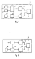
- the preamble section of the frames of the first embodiment as shown in Fig. 4 comprises essentially four parts, namely a training sequence Tr for searching candidate transmission paths, a preamble sequence Pr enabling the estimation of channel quality information in a receiver for that candidate path, a training sequence Tc for a currently used transmission path, and a preamble sequence Pc enabling the estimation of channel quality information in a receiving device for the currently used transmission path as well as the frame timing in the receiving device.
- the receiving device 10 for receiving signals in a wireless communication system according to the present invention is schematically shown in the block diagram of Fig. 2 .
- the receiving device 10 comprises a narrow beam antenna 11 which is adapted to be steered to different positions by an antenna steering means 13 under the control of a control means 14.
- the control means 14 can be any kind of suitable control means, such as a base band processing means of the receiving device 10, or any other suitable control and/or processing device.
- the control means 14 is connected to a memory means 15 adapted to store data, information, applications, software programs and so forth necessary for the operation of the receiving device 10.
- the receiving device 10 further comprises a high frequency section 12 which is adapted to receive signals via the antenna 11, which are then further processed in the usual manner in the receiving device 10.
- a channel estimator 16 is adapted to perform a channel estimation on the basis of received preamble information.
- the channel estimation information derived by the channel estimator 16 can e. g. be used in the control means 14 for steering the antenna 11 to a suitable position via the antenna steering means 13.
- Fig. 2 only shows the necessary elements for understanding the present invention.
- the receiving device 10 would comprise all other necessary elements for the operation of the receiving device 10 enabling the reception of signals in a wireless communication system.
- the receiving device 10 can additionally comprise all necessary elements and functionalities to transmit signals in the wireless communication system either via the antenna 11 or a separate transmission antenna.
- the transmitting device 1 could comprise all necessary elements and functionalities enabling the reception of signals in the wireless communication system either via the antenna 2 or a separate reception antenna. Further, the elements and functionalities of the transmitting device 1 shown and explained in relation to Fig. 1 and of the receiving device 10 shown and explained in relation to Fig. 2 could be combined in a communication device 1 enabling the transmission and reception of signals in the wireless communication system.
- Fig. 3 shows a schematic diagram of various transmission paths between a narrow beam antenna 2' of a transmitting device and a narrow beam antenna 11' of a receiving device.
- the transmitting narrow beam antenna 2' might be the antenna 2 of the transmitting device 1 shown in Fig. 1
- the receiving narrow beam antenna 11' might be the antenna 11 of the receiving device 10 of Fig. 2 .
- the present invention could also function if only the transmitting device or the receiving device has a steerable narrow beam antenna and the other device only has a wide beam or omni-directional antenna.
- a current transmission path P 0 is not a direct line of sight transmission path, but is a transmission path in which the electromagnetic signals are reflected once by an object.
- the direct line of sight transmission path between antenna 2' and antenna 11' is blocked by an obstacle 17.
- Candidate transmission paths, i. e. alternative possible transmission paths between the antenna 2' and the antenna 11' are shown as transmission paths P 1 , P 2 , P 3 and P 4 .
- the candidate transmission paths P 1 , P 3 and P 4 are transmission paths in which the electromagnet signals are reflected once by an object.
- the candidate transmission path P 2 is a candidate transmission path in which the electromagnetic signals are reflected twice on objects. However, all reflections of the candidate transmission paths are in a way that the reflected electromagnetic signal reaches the receiving antenna 11'.
- the currently used transmission path P 0 has the best channel properties, e. g.
- the candidate transmission paths P 1 , P 2 , P 3 and P 4 are shown with broken lines indicating that the channel qualities of these candidate transmission paths are not as good as the one of the currently used transmission path Po. However, in case that the channel qualities of the currently used transmission path Po changes, e. g. if the reflection object moves or if the transmission path is blocked by another object or obstacle due to movement or the like, one of the candidate transmission paths P 1 , P 2 , P 3 and P 4 might become the current transmission path.
- Fig. 3 also visualizes that usually only a quite low number of transmission paths provide a transmission quality which enables the transmission and reception of signals between a transmitter and a receiver.
- HPBW half power beam width
- the present invention now suggests a very simple but elegant and effective way to transmit frames on a current transmission path while monitoring and checking candidate transmission paths from time to time in order to be able to switch to a different transmission path if the currently used transmission path deteriorates. Further, the present invention suggests a new frame structure which reduces the overhead for the measurement of the channel quality and enables the implementation of a fast beam steering algorithm.
- the first embodiment of the frame structure of the present invention shown in Fig. 4 suggests a frame with a structure as described above.
- the control means 5 of the transmitting device 1 causes the antenna steering means 4 to steer the antenna 2 from the position which corresponds to the currently used transmission path to a position which corresponds to a candidate transmission path.
- the control means 14 of the receiving device 10 causes the antenna steering means 13 to steer the antenna 11 to a position which corresponds to the same candidate transmission path so that the training sequence Tr as well as the preamble sequence Pr can be received while the antenna 11 is in the different position corresponding to the candidate transmission path.
- the training sequence Tr enables the synchronization of the receiving device 10 to the transmitting device 1 over the candidate transmission path, e.
- the preamble sequence Pr enables the channel estimator 16 to estimate the channel quality information of the candidate transmission path.
- the antenna 2 of the transmitting device 1 is switched back to the position corresponding to the currently used transmission path.
- the antenna 11 is switched back to the position which corresponds to the currently transmission path.
- the training sequence Tc for the currently used transmission path is transmitted from the transmitting device 1 to the receiving device 11 and enabling synchronization, i. e. timing or carrier recovery, for the currently used transmission path in the receiving device 10.
- the preamble sequence Pc is transmitted from the transmitting device 1 to the receiving device 10 enabling the estimation of accurate channel quality information by the channel estimator 16 in the receiving device 10, as well as enabling the frame timing in the receiving device 10.
- the transmitting device 1 and the receiving device 10 have to have knowledge about the respectively next candidate transmission path to be used in case that both the transmitting device 1 and the receiving device 10 comprise a steerable narrow beam antenna.
- both the transmitting device 1 and the receiving device 10 comprise a steerable narrow beam antenna.
- such previous knowledge is not absolutely necessary, but might be necessary in order to give the transmitting device 1 some feedback about which candidate transmission channel has which channel qualities.
- the corresponding information could e. g.
- the candidate transmission channel which had the best channel quality is chosen to become the current transmission channel and the antennas 2 and 11 are steered to the corresponding positions.
- the frame length Tf or the length of the data part of the frame must be shortened as compared to the frame length Tf of the first embodiment shown in Fig. 4 in order to improve the performance of the frame error rate.
- the bit error rate is equal to 1 x 10 -7
- the data rate is 1 Gps
- the length of the data part is 10ms and if a random error is assumed, since the number of data in each frame is 1 x 10 7 (10ms multiplied with data rate of 1 Gpbs)
- the performance of the frame error rate is very bad.
- the bit error rate is equal to 1 x 10 -7
- the data rate is 1 Gps
- the length of the data part is reduced from 10ms to 100 ⁇ s, the number the data in each frame is 1 x 10 5 , so that the frame error rate becomes better than 1 per cent.
- the length of the training sequence Tr and the preamble sequence Pr are fixed, since they only depend on real circuits, in case that the length of the data part is reduced in each frame, the relative overhead introduced by Tr + Pr in relation to the data part becomes very high. For example, when the length of a data part in a frame is changed from 10ms to 100 ⁇ s, the overhead increases by about 100 times.
- a new physical frame structure according to the second embodiment as shown in Fig.
- a data frame comprising a preamble section with a training sequence Tc and a preamble sequence Pc and a data section, as well as a beam steering frame only comprising a training sequence Tr and a preamble sequence Pr are suggested.
- the training sequences Tr and Tc are identical in their features and functions as the corresponding training sequences Tr and Tc, respectively, shown and explained in relation to Fig. 4 .
- the same is true is for the preamble sequences Pr and Pc, which are identical in features and functions as the corresponding preamble sequences Pr and Pc, respectively, shown and explained in relation to Fig. 4 .
- the fixed speed of the beam steering algorithm does not effect a frame error rate for the data frames.
- the data frames of the second embodiment can be transmitted more frequently than the beam steering frames, so that the overhead introduced by the beam steering frames can be reduced.
- the beam steering frame could be transmitted and received after a certain number of data frames during a regular transmission.
- the frequency of the beam steering frames can be increased in order to find candidate transmission paths with a better channel quality.
- the number of beam steering frames which are transmitted from the transmitting device 1 to the receiving device 10 can be adapted depending on the channel quality estimated in the receiving device for the currently used transmitting path. In case that the channel quality of the currently used transmitting path deteriorates, the number of the beam steering frames is increased.
- the frequency of the beam steering frames in relation to the data frames can be dynamically adjusted based on additional features and/or parameters of the transmitting device 1 and/or the receiving device 10, e. g. the movement of one of the devices, such as the acceleration, rotation and so forth, or any other suitable parameter.
- FIG. 7 An example for an increased frequency of the transmission of beam steering frames is schematically shown in Fig. 7 .
- the data frame of the second embodiment as shown and explained in relation to Fig. 5 can comprise two types, namely a long data frame and a short data frame.
- a long data frame should be transmitted and received immediately after a beam steering frame has been transmitted and received.
- the other data frames are short data frames.
- a long data frame comprises a preamble section with a training sequence Tc(L) and a preamble sequence Pc(L), and a data section.
- the training sequence Tc(L) is a training sequence for the currently used transmission path and has the function to enable the switching of the antennas 2 and 11 (and/or further circuitry) from the position corresponding to the candidate transmission path of the immediately preceding beam steering frame back to the position corresponding to the currently used transmission path, and then to enable synchronization, i. e. timing or carrier recovery, for the currently used transmission path in the receiving device 10.
- the preamble sequence Pc(L) has the function to enable the estimation of accurate channel quality information in the channel estimator 16 of the receiving device 10 for the currently used transmission path as well as the realization of frame timing in the receiving device 10.
- the training sequence Tc(S) of the short data frame only has the function to enable the synchronization, i. e.
- the preamble sequence Pc(S) has the function to enable the estimation of the accurate channel quality information in the channel estimator 16 of the receiving device 10 as well as the realization of the frame timing in the receiving device 10, and therefore has the same length as the preamble sequence Pc(L).
- the length of the data parts of the long data frame and the short data frame are the same.
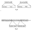
- Tc(L) is relatively long as compared to Tc(S), which does not need to enable a switching of the antenna or other circuitry. Since, as can be seen in Fig. 9 , most of the time only the transmission of a short data frame is necessary instead of the transmission of a long data frame, the overhead of Tc can be reduced dramatically.
- the preamble sequences of the long data frame, the short data frame and the beam steering data frame can advantageously be different from each other in order to facilitate the receiving device 10 to identify which type of frame is being transmitted and received and in order to enable the receiving device to adjust to the respective frame length.
- the various frame types explained in the first and the second embodiment above can be either transmitted in single carriers or in multiple carriers, such as e. g. in an OFDM system.
- the present invention enables the transmission and reception of signals in a wireless communication system with at least one steerable narrow beam antenna, whereby the direction of the at least one narrow beam antenna can be steered with low control overhead and a reduced frame length for high data rate wireless communication, by defining novel frame structures.
- a new frame structure enabling the channel estimation for the currently used transmission path as well as a candidate transmission path is suggested
- two different frame types namely a data frame and a beam steering frame are suggested.
- the overhead for beam steering can be reduced.
- a further overhead reduction can be achieved by defining two different types of data frames in the second embodiment, namely a long data frame and a short data frame as described above.
Description
- The present invention relates to a method and a device for transmitting signals in a wireless communication system, as well as to a receiving device for receiving signals in a wireless communication system with a special frame structure enabling a high data rate transmission and reception with at least one steerable narrow beam (sharp beam) antenna.
- Wireless communication is used in a large variety of technical fields, such as mobile telephone, wireless LAN, walky-talkies, broadcast radio systems, point-to-point radio systems and many other known and future applications. The communication radius covered by a respective wireless communication system basically depends on the technique used. Whereas cellular communication systems, such as the GSM and the UMTS system, are adapted for a communication radius up to about 10km (or more), wireless LAN is in the range of about 100m (or more) and the Bluetooth system is in the range of several 10m (or more). The major influences on the communication range of a wireless communication system are the transmission frequency and output power used. Although only little absorption of electromagnetic waves in the atmosphere occurs at the transmission frequency used for GSM and UMTS, a significant absorption occurs in the 60GHz range, which makes the later range quite well suited for low range and indoor wireless communication. Furthermore, the kind of transmission and/or reception antennas used for a respective wireless communication technique varies depending on a respective field of application. For example, if a number of receivers has to be reached or if the location of the receivers is unknown or varies frequently, e. g. due to movement, wide beam antennas or omni-directional antennas are sometimes used. However, the utilization of wide beam antennas in high data rate millimeter wave wireless communication systems is problematic, because of the multipath fading effect. For example, if wide beam antennas are used both on the transmitter and the receiver side and if the direct line of sight (LOS) link is blocked by an obstacle, such as a moving human being, a vehicle or the like, there exist a lot of reflection paths between the transmitter and the receiver, i. e. transmission paths in which the transmitted electromagnetic wave is reflected at least once by objects before it reaches the receiver. The channel delay spread might be over tens of symbol periods when the data rate is high, e. g. over 1Gbps, which leads to severe inter-symbol interference due to deep frequency selective fading.
-
US 2004/0185782 A1 proposes a concept for selecting between the signal paths of an antenna system. A selection technique with an antenna system of the steerable beam type is presented, in which directionally distinct beams are formed. Another selection technique is described wherein the antenna system is of the diversity switching type, in which multiple, distinct antennas are used. Said techniques try to reduce the number of lost frames by switching the transmission path dependent on signal quality. - Two conventional solutions exist for such kind of non line of sight (NLOS) user scenarios, whereby both of these solutions need high-speed and complex signal processing circuits. One solution adopts a channel equalizer including linear, decision feedback or maximum likelihood sequence estimation (MLSE) equalizer. When the channel delay spread is much longer than the symbol duration, the equalizer becomes complex and needs a lot of processing power. Another solution is the orthogonal frequency division multiplexing (OFDM) technique, which is already adopted in wireless LAN systems. However, due to its inherent linear modulation and high peak to average ratio problems, the power consumption of the power amplifier (PA) in such systems is very high. Obviously, a high speed Fast Fourier Transformation and other signal processing modules are required for demodulating a 1Gbps signal. Therefore, it is important to find other solutions which do not require complex and high speed base band circuitry for high data rate millimeter wave range communication systems.
- The above objections are achieved by a method for transmitting signals in a wireless communication system according to
claim 1, a transmitting device for transmitting signals in a wireless communication system according toclaim 6 and a receiving device for receiving signals in a wireless communication system according to claim 11. - According to the present invention, a method for transmitting signals in a wireless communication system, in which signals are transmitted from a first communication device to a second communication device, said signals being transmitted in consecutive frames, each frame having a preamble section comprising preamble information, at least one of said first and said second communication devices having an antenna with an antenna beam having a beam direction which is more predominant than other beam directions and which is adapted to be steered to different positions, each of said different positions corresponding to one of a number of different transmission paths from said first to said second communication device, comprises the steps of transmitting and receiving a first preamble section comprising preamble information enabling the estimation of a channel quality of a current transmission paths, while said antenna is in a current position corresponding to said current transmission path, steering said antenna from said current position to a different position corresponding to a candidate transmission path, and transmitting and receiving a second preamble section comprising preamble information enabling the estimation of a channel quality of said candidate transmission path while said antenna is in said different position.
- According to the invention, the first and the second preamble section are transmitted in different frames. Hereby, the number of transmitted frames comprising a second preamble section in relation to the number of transmitted frames comprising a first preamble section is varied depending on a detected channel quality for the current transmission path. Further advantageously, the number of transmitted frames comprising a second preamble section in relation to the number of transmitted frames comprising a first preamble section is varied depending on a detected movement information in relation to the first and/or the second communication device. Further advantageously, after each frame comprising a second preamble section a frame comprising a first preamble section with a longer length as compared to the normally transmitted frames comprising a first preamble section is transmitted. Further advantageously, the first and the second preamble sections are different from each other.
- According to the present invention, a transmitting device for transmitting signals in a wireless communication system, wherein said signals are transmitted in consecutive frames, each frame having a preamble section with preamble information, comprises an antenna with an antenna beam having a beam direction which is more predominant than other beam directions and adapted to be steered to different positions, each of said different positions corresponding to one of a number of different transmission paths from said transmitting device to a receiving device, a steering means adapted to steer said antenna to different positions, preamble generating means adapted to generate preamble sections comprising preamble information, control means adapted to control the transmission of a first preamble section comprising preamble information enabling the estimation of a channel quality of a current transmission path while said antenna is in a current position corresponding to said current transmission path, and further adapted to control the transmission of a second preamble section comprising preamble information enabling the estimation of a channel quality of a candidate transmission path after said antenna has been steered to a different position corresponding to said candidate transmission path.
- According to the invention, the control means is adapted to control the transmission of signals in which said first and said second preamble section are transmitted in different frames. Hereby, the control means is adapted to vary the number of frames comprising a second preamble section in relation to the number of frames comprising a first preamble section depending on a detected channel quality for the current transmission path. Further advantageously, the control means is adapted to vary the number of transmitted frames comprising a second preamble section in relation to the number of transmitted frames comprising a first preamble section depending on a detected movement information in relation to the transmission and/or the receiving device. Hereby, the control means is advantageously adapted to control the transmission of signals so that after each frame comprising a second preamble section a frame comprising a first preamble section with a longer length as compared to the normally transmitted frames comprising a first preamble section is transmitted. Advantageously, the first and the second preamble sections are different from each other.
- According to the present invention, a receiving device for receiving signals in a wireless communication system, wherein said signals are transmitted and received in consecutive frames, each frame having a preamble section with preamble information, comprises an antenna with an antenna beam having a beam direction which is more predominant than other beam directions and adapted to be steered to different positions, each of said different positions corresponding to one of a number of different transmission paths from a transmitting device to a receiving device, a steering means adapted to steer said antenna to different positions, channel estimation means adapted to estimate a channel quality on the basis of received preamble information, control means adapted to control the reception of a first preamble section comprising preamble information enabling the estimation of a channel quality of a current transmission path while said antenna is in a current position corresponding to said current transmission path, and further adapted to control the reception of a second preamble section comprising preamble information enabling the estimation of a channel quality of a candidate transmission path after said antenna has been steered to a different position corresponding to said candidate transmission path.
- According to the invention, the control means is adapted to control the reception of signals in which said first and said second preamble section are transmitted in different frames. Hereby, the control means is adapted to control the reception of signals in which the number of frames comprising a second preamble section in relation to the number of frames comprising a first preamble section is varied depending on the detected channel quality for the current transmission path. Hereby, the control means is advantageously adapted to control the reception of signals in which the number of transmitted frames comprising a second preamble section in relation to the number of transmitted frames comprising a first preamble section is varied depending on a detected movement information in relation to the first and/or the second communication device. The control means is further advantageously adapted to control the reception of signals so that after each frame comprising a second preamble section a frame comprising a first preamble section with a longer length as compared to the normally transmitted frames comprising a first preamble section is received. Further, the control means is advantageously adapted to control the reception of first and second preamble sections which are different from each other.
- The present invention therefore provides a solution for a high data rate wireless communication in the millimeter wave length range which does not require a complex and high-speed processing. Specifically, when the transmission data rate becomes high, e. g. in the range of or over 1 Gbps, the frame length should be shortened in order to keep the performance of the frame error rate (FER) under the same bit error rate (BER). When the frame length becomes shorter, the overhead, i. e. the preamble information, necessary for the beam steering algorithm is higher. The present invention enables to reduce this overhead by defining a new frame structure including the definition of different types of frames, and how to combine these new types of frames together to enable both a wireless data communication with a high data rate and an antenna steering. The specific advantages of the present invention are that the additional overhead for the beam steering is low, the frame length can be shortened for high data wireless communication systems in order to improve the performance of the frame error rate under the same bit error rate, and the speed of the beam steering can be increased.
- It is to be noted that the present invention can be applied to any kind of wireless communication system which enables the transmission and reception of signals over any kind of range. Further, the present invention is not restricted to any kind of modulation system or technical implementation of the wireless communication. Some embodiments and implementations of the present invention, however, might be advantageous in short and/or mid range wireless communication systems in which signals are transmitted in the millimeter wave length range, as e. g. the 60Ghz transmission range. Further, the transmitting device and the receiving device of the present invention can be any kind of device adapted to transmit and receive, respectively, signals in a wireless communication system. The terms 'transmitting device' and 'receiving device' are hereby intended to comprise any kind of portable and/or stationary communication equipment, unit, means, system and so forth. The signals to be transmitted from the transmitting device to the receiving device according to the present invention may comprise any kind of information, data, symbols and so forth which can be transmitted from a transmitter to a receiver for any kind of reason and utility. According to embodiments of the present invention, at least one of the transmitting device and the receiving device comprise a narrow beam antenna which is adapted to be steered to different positions. In some implementations it might be preferable that the transmitting device and the receiving device each comprise a narrow beam antenna which is adapted to be steered to different positions. The term 'narrow beam antenna' is hereby intended to comprise and cover all kinds of antennas which, in contrary to omni-directional antennas which do not have a specific transmission and/or reception direction, have a specific transmission and/or reception direction without any limitation to the specific shape of the antenna beam. Further, the narrow beam antenna of embodiments of the present invention is not restricted to any specific steering type, i. e. the specific technical implementation which enables the steering or switching of the narrow beam antenna to different transmitting and/or reception positions is not as important as long as the transmitting and/or receiving direction of the narrow beam antenna can be changed, switched, varied and the like. For example, but not exclusively, a narrow beam antenna according to embodiments of the present invention may be an antenna with a fixed narrow beam radiation pattern, which can be varied by mechanically or electrically shifting the antenna so that the beam direction is varied. Further, the narrow beam antenna could be an antenna type which can be steered by changing the phase and/or the gain of the antenna so that the beam direction changes. As a further alternative, the narrow beam antenna could consist of an antenna pattern, whereby each of the antenna elements of the antenna pattern has a specific narrow beam antenna direction and the elements can be controlled in a way that the beam direction of the antenna is changed. Many other examples of steerable narrow beam antennas can be made, which are currently known or which may be developed in the future, but which would fall under the scope of the present invention.
- The present invention will be explained in more detail in the following description of preferred embodiments in relation to the enclosed drawings, in which
-
Fig. 1 schematically shows a transmitting device according to the present invention, -
Fig. 2 schematically shows a receiving device according to the present invention, -
Fig. 3 schematically shows a variety of transmission paths between a transmitter and a receiver, -
Fig. 4 schematically shows a first embodiment of a frame according to the present invention, -
Fig. 5 schematically shows a second embodiment of frames according to the present invention, -
Fig. 6 schematically shows the implementation of the second embodiment in consecutive frames, -
Fig. 7 schematically shows the implementation of the second embodiment in a consecutive number of frames, -
Fig. 8 schematically shows a further variation of frames within the second embodiment, and -
Fig. 9 schematically shows the implementation of the frames ofFig. 8 in a number of consecutive frames. -
Fig. 1 shows a schematic block diagram of a transmitting device for transmitting signals in a wireless communication system according to the present invention. Hereby, the transmittingdevice 1 of the present invention as shown inFig. 1 is only displayed with elements which are necessary for the implementation and the understanding of the present invention. All other necessary elements enabling the transmittingdevice 1 to transmit signals in a wireless communication system are not shown for the sake of clarity. However, in a practical implementation, all such elements would be implemented. - The transmitting
device 1 comprises anarrow beam antenna 2 which is adapted to be steered to different positions under the control of an antenna steering means 4, which itself is controlled by a control means 5. The control means 5 can be a base band processing and/or controlling means of the transmittingdevice 1 or any other suitable control unit. The control means 5 is connected to amemory 6 for storing data, information, applications, software code and so forth. - The transmitting
device 1 is adapted to transmit signals in consecutive time frames, whereby each frame has a preamble section comprising preamble information. Examples of such frames are shown inFigs. 4, 5 and8 . Examples for a number of consecutive time frames transmitted by the transmittingdevice 1 are shown inFigs. 6, 7 and9 . Hereby, it is to be understood that the term 'consecutive' does not necessarily mean that the frames are transmitted immediately one after the other. In some implementations there might be an interval Tg between two consecutive frames, which e. g. can be used to handle the clock difference between a transmittingdevice 1 and a receiving side, such as the receivingdevice 10 as shown and explained inFig. 2 , in order to support long time and high rate wireless communications, such as wireless high definition television or the like. In the following description and explanations, the interval Tg between two consecutive time frames is assumed to be zero. In a first embodiment of the frame structure according to the present invention which is shown inFig. 4 , a frame, such as frame No. 1 shown inFig. 4 having a length of Tf, comprises a preamble section and a data section. The preamble section is generated by a preamble section generator 9 of the transmittingdevice 1, whereby the preamble generation can either take place in the frequency domain or the time domain processing. Further, the preambles generated by the preamble section generator 9 can have different lengths and sizes depending on the wanted implementation. The frames are formed by a frame generator 7 which obtains the preamble sections from the preamble section generator 9 and the data from the data means 8. The data means 8 generates, collects, or obtains the data in any kind of suitable way and forwards the data to the frame generator 7. After a frame has been generated by the frame generator 7, the generated frames are then further processed in the usual manner, e. g. by modulating the frame information into frequency signals or the like, which are then up-converted and transmitted via a high frequency means 3 through thenarrow beam antenna 2. - The preamble section of the frames of the first embodiment as shown in
Fig. 4 comprises essentially four parts, namely a training sequence Tr for searching candidate transmission paths, a preamble sequence Pr enabling the estimation of channel quality information in a receiver for that candidate path, a training sequence Tc for a currently used transmission path, and a preamble sequence Pc enabling the estimation of channel quality information in a receiving device for the currently used transmission path as well as the frame timing in the receiving device. - An example of a receiving
device 10 for receiving signals in a wireless communication system according to the present invention is schematically shown in the block diagram ofFig. 2 . The receivingdevice 10 comprises a narrow beam antenna 11 which is adapted to be steered to different positions by an antenna steering means 13 under the control of a control means 14. The control means 14 can be any kind of suitable control means, such as a base band processing means of the receivingdevice 10, or any other suitable control and/or processing device. The control means 14 is connected to a memory means 15 adapted to store data, information, applications, software programs and so forth necessary for the operation of the receivingdevice 10. The receivingdevice 10 further comprises ahigh frequency section 12 which is adapted to receive signals via the antenna 11, which are then further processed in the usual manner in the receivingdevice 10. For example, achannel estimator 16 is adapted to perform a channel estimation on the basis of received preamble information. The channel estimation information derived by thechannel estimator 16 can e. g. be used in the control means 14 for steering the antenna 11 to a suitable position via the antenna steering means 13. It is to be noted thatFig. 2 only shows the necessary elements for understanding the present invention. In a practical implementation the receivingdevice 10 would comprise all other necessary elements for the operation of the receivingdevice 10 enabling the reception of signals in a wireless communication system. Further, it is to be noted that the receivingdevice 10 can additionally comprise all necessary elements and functionalities to transmit signals in the wireless communication system either via the antenna 11 or a separate transmission antenna. Likewise, the transmittingdevice 1 could comprise all necessary elements and functionalities enabling the reception of signals in the wireless communication system either via theantenna 2 or a separate reception antenna. Further, the elements and functionalities of the transmittingdevice 1 shown and explained in relation toFig. 1 and of the receivingdevice 10 shown and explained in relation toFig. 2 could be combined in acommunication device 1 enabling the transmission and reception of signals in the wireless communication system. -
Fig. 3 shows a schematic diagram of various transmission paths between a narrow beam antenna 2' of a transmitting device and a narrow beam antenna 11' of a receiving device. The transmitting narrow beam antenna 2' might be theantenna 2 of the transmittingdevice 1 shown inFig. 1 and the receiving narrow beam antenna 11' might be the antenna 11 of the receivingdevice 10 ofFig. 2 . However, it is to be understood that the present invention could also function if only the transmitting device or the receiving device has a steerable narrow beam antenna and the other device only has a wide beam or omni-directional antenna. As shown inFig. 3 , a current transmission path P0 is not a direct line of sight transmission path, but is a transmission path in which the electromagnetic signals are reflected once by an object. The direct line of sight transmission path between antenna 2' and antenna 11' is blocked by anobstacle 17. Candidate transmission paths, i. e. alternative possible transmission paths between the antenna 2' and the antenna 11' are shown as transmission paths P1, P2, P3 and P4. The candidate transmission paths P1, P3 and P4 are transmission paths in which the electromagnet signals are reflected once by an object. The candidate transmission path P2 is a candidate transmission path in which the electromagnetic signals are reflected twice on objects. However, all reflections of the candidate transmission paths are in a way that the reflected electromagnetic signal reaches the receiving antenna 11'. However, in the example shown inFig. 3 , the currently used transmission path P0 has the best channel properties, e. g. the strongest signal to noise ratio or any other suitable parameter, and is therefore currently used for transmitting frames between the transmitter and the receiver. The candidate transmission paths P1, P2, P3 and P4 are shown with broken lines indicating that the channel qualities of these candidate transmission paths are not as good as the one of the currently used transmission path Po. However, in case that the channel qualities of the currently used transmission path Po changes, e. g. if the reflection object moves or if the transmission path is blocked by another object or obstacle due to movement or the like, one of the candidate transmission paths P1, P2, P3 and P4 might become the current transmission path. - Generally,
Fig. 3 also visualizes that usually only a quite low number of transmission paths provide a transmission quality which enables the transmission and reception of signals between a transmitter and a receiver. In order to find and monitor all sufficiently strong transmission paths, it is necessary to search and monitor all available and possible transmission paths, whereby the transmitting narrow beam antenna 2' and the receiving narrow beam antenna 11' have a lot of two-dimensional choices. For example, if the scanning range is 100 degrees and the half power beam width (HPBW) of the sharp beam steering antenna is 20 degrees, then the number of choices from each side is 5 x 5 = 25 and the total number of choices for both the transmission and the receiving side is 25 x 25 = 625. The resulting calculation complexity is very high. - The present invention now suggests a very simple but elegant and effective way to transmit frames on a current transmission path while monitoring and checking candidate transmission paths from time to time in order to be able to switch to a different transmission path if the currently used transmission path deteriorates. Further, the present invention suggests a new frame structure which reduces the overhead for the measurement of the channel quality and enables the implementation of a fast beam steering algorithm.
- As stated above, the first embodiment of the frame structure of the present invention shown in
Fig. 4 suggests a frame with a structure as described above. During the training sequence Tr, the control means 5 of the transmittingdevice 1 causes the antenna steering means 4 to steer theantenna 2 from the position which corresponds to the currently used transmission path to a position which corresponds to a candidate transmission path. At the same time, the control means 14 of the receivingdevice 10 causes the antenna steering means 13 to steer the antenna 11 to a position which corresponds to the same candidate transmission path so that the training sequence Tr as well as the preamble sequence Pr can be received while the antenna 11 is in the different position corresponding to the candidate transmission path. The training sequence Tr enables the synchronization of the receivingdevice 10 to the transmittingdevice 1 over the candidate transmission path, e. g. for timing or carrier recovery, whereas the preamble sequence Pr enables thechannel estimator 16 to estimate the channel quality information of the candidate transmission path. After transmission of the preamble sequence Pr, theantenna 2 of the transmittingdevice 1 is switched back to the position corresponding to the currently used transmission path. After receipt of the preamble sequence Pr, the antenna 11 is switched back to the position which corresponds to the currently transmission path. Thereafter, the training sequence Tc for the currently used transmission path is transmitted from the transmittingdevice 1 to the receiving device 11 and enabling synchronization, i. e. timing or carrier recovery, for the currently used transmission path in the receivingdevice 10. Afterwards, the preamble sequence Pc is transmitted from the transmittingdevice 1 to the receivingdevice 10 enabling the estimation of accurate channel quality information by thechannel estimator 16 in the receivingdevice 10, as well as enabling the frame timing in the receivingdevice 10. - It has to be understood, and that is true for all embodiments of the present invention explained herein that the transmitting
device 1 and the receivingdevice 10 have to have knowledge about the respectively next candidate transmission path to be used in case that both the transmittingdevice 1 and the receivingdevice 10 comprise a steerable narrow beam antenna. In case that only one of the transmittingdevice 1 and the receivingdevice 10 comprise a steerable narrow beam antenna, such previous knowledge is not absolutely necessary, but might be necessary in order to give thetransmitting device 1 some feedback about which candidate transmission channel has which channel qualities. Hereby, the corresponding information could e. g. be stored in the memory means 15 of the receivingdevice 10 and/or the memory means 6 of the transmittingdevice 1, so that in case that the current transmission channel breaks down, the candidate transmission channel which had the best channel quality is chosen to become the current transmission channel and theantennas 2 and 11 are steered to the corresponding positions. - In case that the data rate should become higher, e. g. in the range of 1 Gbps, the frame length Tf or the length of the data part of the frame must be shortened as compared to the frame length Tf of the first embodiment shown in
Fig. 4 in order to improve the performance of the frame error rate. For example, if the bit error rate is equal to 1 x 10⁻⁷, if the data rate is 1 Gps, if it is assumed that the length of the data part is 10ms and if a random error is assumed, since the number of data in each frame is 1 x 10⁷ (10ms multiplied with data rate of 1 Gpbs), the performance of the frame error rate is very bad. However, if e.g. the length of the data part is reduced from 10ms to 100 µs, the number the data in each frame is 1 x 10⁵, so that the frame error rate becomes better than 1 per cent. Since the length of the training sequence Tr and the preamble sequence Pr are fixed, since they only depend on real circuits, in case that the length of the data part is reduced in each frame, the relative overhead introduced by Tr + Pr in relation to the data part becomes very high. For example, when the length of a data part in a frame is changed from 10ms to 100 µs, the overhead increases by about 100 times. In order to solve this problem, a new physical frame structure according to the second embodiment as shown inFig. 5 is suggested, which comprises two different types of physical layer frames, namely a data frame comprising a preamble section with a training sequence Tc and a preamble sequence Pc and a data section, as well as a beam steering frame only comprising a training sequence Tr and a preamble sequence Pr are suggested. The training sequences Tr and Tc are identical in their features and functions as the corresponding training sequences Tr and Tc, respectively, shown and explained in relation toFig. 4 . The same is true is for the preamble sequences Pr and Pc, which are identical in features and functions as the corresponding preamble sequences Pr and Pc, respectively, shown and explained in relation toFig. 4 . - As a result, by introducing the separate beam steering frames, which only and exclusively comprise the training sequence Tr and the preamble sequence Pr, the fixed speed of the beam steering algorithm does not effect a frame error rate for the data frames. As schematically illustrated in
Fig. 6 , the data frames of the second embodiment can be transmitted more frequently than the beam steering frames, so that the overhead introduced by the beam steering frames can be reduced. For example, the beam steering frame could be transmitted and received after a certain number of data frames during a regular transmission. However, in case that the channel quality of the currently used transmission path as estimated in thechannel estimator 16 of the receivingdevice 10 deteriorates, the frequency of the beam steering frames can be increased in order to find candidate transmission paths with a better channel quality. In other words, the number of beam steering frames which are transmitted from the transmittingdevice 1 to the receivingdevice 10 can be adapted depending on the channel quality estimated in the receiving device for the currently used transmitting path. In case that the channel quality of the currently used transmitting path deteriorates, the number of the beam steering frames is increased. Alternatively or additionally, the frequency of the beam steering frames in relation to the data frames can be dynamically adjusted based on additional features and/or parameters of the transmittingdevice 1 and/or the receivingdevice 10, e. g. the movement of one of the devices, such as the acceleration, rotation and so forth, or any other suitable parameter. - An example for an increased frequency of the transmission of beam steering frames is schematically shown in
Fig. 7 . - As shown in
Fig. 8 , the data frame of the second embodiment as shown and explained in relation toFig. 5 can comprise two types, namely a long data frame and a short data frame. As shown inFig. 9 , according to the present invention, it is suggested that a long data frame should be transmitted and received immediately after a beam steering frame has been transmitted and received. The other data frames are short data frames. Hereby, a long data frame comprises a preamble section with a training sequence Tc(L) and a preamble sequence Pc(L), and a data section. The training sequence Tc(L) is a training sequence for the currently used transmission path and has the function to enable the switching of theantennas 2 and 11 (and/or further circuitry) from the position corresponding to the candidate transmission path of the immediately preceding beam steering frame back to the position corresponding to the currently used transmission path, and then to enable synchronization, i. e. timing or carrier recovery, for the currently used transmission path in the receivingdevice 10. The preamble sequence Pc(L) has the function to enable the estimation of accurate channel quality information in thechannel estimator 16 of the receivingdevice 10 for the currently used transmission path as well as the realization of frame timing in the receivingdevice 10. The training sequence Tc(S) of the short data frame only has the function to enable the synchronization, i. e. timing or carrier recovery, for the currently used transmission path in the receivingdevice 10, so that the length of Tc(S) is shorter than the length of Tc(L). In case that a re-synchronization of the receivingdevice 10 is not necessary, Tc(S) can be omitted. The preamble sequence Pc(S) has the function to enable the estimation of the accurate channel quality information in thechannel estimator 16 of the receivingdevice 10 as well as the realization of the frame timing in the receivingdevice 10, and therefore has the same length as the preamble sequence Pc(L). The length of the data parts of the long data frame and the short data frame are the same. - As stated above, in a long data frame, due to the requirement of switching the antenna (or other circuitry) back from the candidate transmission path to the currently used transmission path and of the re-synchronization for the currently used transmission path, Tc(L) is relatively long as compared to Tc(S), which does not need to enable a switching of the antenna or other circuitry. Since, as can be seen in
Fig. 9 , most of the time only the transmission of a short data frame is necessary instead of the transmission of a long data frame, the overhead of Tc can be reduced dramatically. - The preamble sequences of the long data frame, the short data frame and the beam steering data frame can advantageously be different from each other in order to facilitate the receiving
device 10 to identify which type of frame is being transmitted and received and in order to enable the receiving device to adjust to the respective frame length. Further, the various frame types explained in the first and the second embodiment above can be either transmitted in single carriers or in multiple carriers, such as e. g. in an OFDM system. - Generally, the present invention enables the transmission and reception of signals in a wireless communication system with at least one steerable narrow beam antenna, whereby the direction of the at least one narrow beam antenna can be steered with low control overhead and a reduced frame length for high data rate wireless communication, by defining novel frame structures. From a physical layer point of view, in a first embodiment a new frame structure enabling the channel estimation for the currently used transmission path as well as a candidate transmission path is suggested, whereas in a second embodiment two different frame types, namely a data frame and a beam steering frame are suggested. Hereby, the overhead for beam steering can be reduced. A further overhead reduction can be achieved by defining two different types of data frames in the second embodiment, namely a long data frame and a short data frame as described above.
Claims (15)
- Method for transmitting signals in a wireless communication system,
in which signals are transmitted from a first communication device to a second communication device, said signals being transmitted in consecutive frames, each frame having a preamble section comprising preamble information, at least one of said first and said second communication devices having an antenna with an antenna beam having a beam direction which is more predominant than other beam directions and which is adapted to be steered to different positions, each of said different positions corresponding to one of a number of different transmission paths from said first to said second communication device, comprising the steps of
transmitting and receiving a first preamble section comprising preamble information enabling the estimation of a channel quality of a current transmission path, while said antenna is in a current position corresponding to said current transmission path, steering said antenna from said current position to a different position corresponding to a candidate transmission path, and
transmitting and receiving a second preamble section comprising preamble information enabling the estimation of a channel quality of said candidate transmission path while said antenna is in said different position, and characterized in that said first and said second preamble section are transmitted in different frames, and
in that the number of transmitted frames comprising a second preamble section in relation to the number of transmitted frames comprising a first preamble section is varied depending on a detected channel quality for the current transmission path. - Method according to claim 1,
wherein said antenna is a narrow beam antenna. - Method according to any preceding claim,
wherein the number of transmitted frames comprising a second preamble section in relation to the number of transmitted frames comprising a first preamble section is varied depending on a detected movement information in relation to the first and/or the second communication device. - Method according to any preceding claim,
wherein after each frame comprising a second preamble section a frame comprising a first preamble section with a longer length as compared to the normally transmitted frames comprising a first preamble section is transmitted. - Method according to any preceding claim,
wherein the first and second preamble sections are different from each other. - Transmitting device for (1) transmitting signals in a wireless communication system, wherein said signals are transmitted in consecutive frames, each frame having a preamble section with preamble information, comprising
an antenna (2) with an antenna beam having a beam direction which is more predominant than other beam directions and adapted to be steered to different positions, each of said different positions corresponding to one of a number of different transmission paths from said transmitting device to a receiving device,
a steering means (4) adapted to steer said antenna (2) to different positions,
preamble generating means (9) adapted to generate preamble sections comprising preamble information,
control means (5) adapted to control the transmission of a first preamble section comprising preamble information enabling the estimation of a channel quality of a current transmission path while said antenna (2) is in a current position corresponding to said current transmission path, and further adapted to control the transmission of a second preamble section comprising preamble information enabling the estimation of a channel quality of a candidate transmission path after said antenna (2) has been steered to a different position corresponding to said candidate transmission path,
and characterized in that said control means (5) is adapted to control the transmission of signals in which said first and said second preamble section are transmitted in different frames, and in that
said control means (5) is adapted to vary the number of transmitted frames comprising a second preamble section in relation to the number of transmitted frames comprising a first preamble section depending on a detected channel quality for the current transmission path. - Transmitting device (1) according to claim 6,
wherein said antenna (2) is a narrow beam antenna. - Transmitting device (1) according to claim 6 or 7,
wherein said control means (5) is adapted to vary the number of transmitted frames comprising a second preamble section in relation to the number of transmitted frames comprising a first preamble section depending on a detected movement information in relation to the transmission and/or receiving device. - Transmitting device according to claim 6 or 7,
wherein said control means (5) is adapted to control the transmission of signals so that after each frame comprising a second preamble section a frame comprising a first preamble section with a longer length as compared to the normally transmitted frames comprising a first preamble section is transmitted. - Transmitting device (1) according to claim 6 or 7,
wherein the first and second preamble sections are different from each other. - Receiving device (10) for receiving signals in a wireless communication system,
wherein said signals are transmitted and received in consecutive frames, each frame having a preamble section with preamble information, comprising an antenna (11) with an antenna beam having a beam direction which is more predominant than other beam directions and adapted to be steered to different positions, each of said different positions corresponding to one of a number of different transmission paths from a transmitting device to said receiving device, a steering means (13) adapted to steer said antenna (11) to different positions, channel estimation means (16) adapted to estimate a channel quality on the basis of received preamble information,
control means (14) adapted to control the reception of a first preamble section comprising preamble information enabling the estimation of a channel quality of a current transmission path while said antenna (11) is in a current position corresponding to said current transmission path, and further adapted control the reception of a second preamble section comprising preamble information enabling the estimation of a channel quality of a candidate transmission path after said antenna (11) has been steered to a different position corresponding to said candidate transmission path, and characterized in that said control means (14) is adapted to control the reception of signals in which said first and said second preamble section are transmitted in different frames, and in that said control means (14) is adapted to to control the reception of signals in which the number of transmitted frames comprising a second preamble section in relation to the number of transmitted frames comprising a first preamble section is varied depending on a detected channel quality for the current transmission path. - Receiving device (10) according to claim 11,
wherein said antenna (11) is a narrow beam antenna. - Receiving device (10) according to claim 11 or 12,
wherein said control means (14) is adapted to control the reception of signals in which the number of transmitted frames comprising a preamble section in relation to the number of transmitted frames comprising a first preamble section is varied depending on a detected movement information in relation to the transmitting and/or receiving device. - Receiving device (10) according to claim 11 or 12,
wherein said control means (14) is adapted to control the reception of signals so that after each frame comprising a second preamble section a frame comprising a first preamble section with a longer length as compared to the normally transmitted frames comprising a first preamble section is received. - Receiving device (10) according to claim 11 or 12,
wherein said control means is adapted to control the reception of first and second preamble sections which are different from each other.
Priority Applications (1)
| Application Number | Priority Date | Filing Date | Title |
|---|---|---|---|
| EP10186593A EP2296294B1 (en) | 2006-10-09 | 2006-10-09 | Method and devices for transmitting and receiving signals in a wireless communication system with a special frame structure |
Applications Claiming Priority (2)
| Application Number | Priority Date | Filing Date | Title |
|---|---|---|---|
| EP10186593A EP2296294B1 (en) | 2006-10-09 | 2006-10-09 | Method and devices for transmitting and receiving signals in a wireless communication system with a special frame structure |
| EP06021151A EP1912346B1 (en) | 2006-10-09 | 2006-10-09 | Method and devices for transmitting and receiving signals in a wireless communication system with a special frame structure |
Related Parent Applications (1)
| Application Number | Title | Priority Date | Filing Date |
|---|---|---|---|
| EP06021151.3 Division | 2006-10-09 |
Publications (2)
| Publication Number | Publication Date |
|---|---|
| EP2296294A1 EP2296294A1 (en) | 2011-03-16 |
| EP2296294B1 true EP2296294B1 (en) | 2013-01-09 |
Family
ID=37890146
Family Applications (2)
| Application Number | Title | Priority Date | Filing Date |
|---|---|---|---|
| EP10186593A Expired - Fee Related EP2296294B1 (en) | 2006-10-09 | 2006-10-09 | Method and devices for transmitting and receiving signals in a wireless communication system with a special frame structure |
| EP06021151A Expired - Fee Related EP1912346B1 (en) | 2006-10-09 | 2006-10-09 | Method and devices for transmitting and receiving signals in a wireless communication system with a special frame structure |
Family Applications After (1)
| Application Number | Title | Priority Date | Filing Date |
|---|---|---|---|
| EP06021151A Expired - Fee Related EP1912346B1 (en) | 2006-10-09 | 2006-10-09 | Method and devices for transmitting and receiving signals in a wireless communication system with a special frame structure |
Country Status (5)
| Country | Link |
|---|---|
| US (2) | US7511663B2 (en) |
| EP (2) | EP2296294B1 (en) |
| JP (1) | JP5038843B2 (en) |
| CN (1) | CN101163343B (en) |
| DE (1) | DE602006021752D1 (en) |
Families Citing this family (21)
| Publication number | Priority date | Publication date | Assignee | Title |
|---|---|---|---|---|
| DE602006021752D1 (en) * | 2006-10-09 | 2011-06-16 | Sony Deutschland Gmbh | Method and apparatus for transmitting and receiving signals in a wireless communication system with a special frame structure |
| US9865240B2 (en) * | 2006-12-29 | 2018-01-09 | Harman International Industries, Incorporated | Command interface for generating personalized audio content |
| EP1956732B1 (en) | 2007-02-07 | 2011-04-06 | Sony Deutschland GmbH | Method for transmitting signals in a wireless communication system and communication system |
| EP1976149B1 (en) * | 2007-03-29 | 2011-10-19 | Sony Deutschland GmbH | Method and device for transmitting signals in a wireless communication system and method and device for receiving signals in a wireless communication system |
| JP2009171458A (en) * | 2008-01-18 | 2009-07-30 | Toshiba Tec Corp | Communication terminal, and mobile communication system |
| EP2099187B1 (en) * | 2008-03-07 | 2011-05-25 | Sony Corporation | Wireless system using a new type of preamble for a burst frame |
| US8630588B2 (en) * | 2008-10-29 | 2014-01-14 | Marvell World Trade Ltd. | Efficient and flexible transmit beamforming sector sweep in a multi-antenna communication device |
| US9787371B2 (en) * | 2008-11-12 | 2017-10-10 | Qualcomm, Incorporated | Method and apparatus for directional channel access in a wireless communications system |
| WO2010099040A1 (en) * | 2009-02-24 | 2010-09-02 | Marvell World Trade Ltd. | Techniques for flexible and efficient beamforming |
| JP2010252049A (en) * | 2009-04-15 | 2010-11-04 | Sony Corp | Communication apparatus, communication method, computer program, and communication system |
| US9178593B1 (en) | 2009-04-21 | 2015-11-03 | Marvell International Ltd. | Directional channel measurement and interference avoidance |
| US8223072B2 (en) * | 2009-04-29 | 2012-07-17 | Aruba Networks, Inc. | Multi-pattern wireless frame transmission |
| GB2479197B (en) * | 2010-04-01 | 2013-05-15 | Canon Kk | Configuring a receiving antenna of a receiving device |
| EP2661033B1 (en) | 2012-05-03 | 2018-07-11 | MediaTek Singapore Pte Ltd. | Beam-change indication for channel estimation improvement in wireless networks |
| US9456357B2 (en) | 2012-07-27 | 2016-09-27 | Aruba Networks, Inc. | Adaptive antenna pattern management for wireless local area networks |
| EP3076739B1 (en) * | 2015-04-01 | 2019-05-01 | HTC Corporation | Device and network of handling data transmission in unlicensed band |
| US10638479B2 (en) * | 2015-11-17 | 2020-04-28 | Futurewei Technologies, Inc. | System and method for multi-source channel estimation |
| WO2018031825A1 (en) * | 2016-08-10 | 2018-02-15 | Intel IP Corporation | System and method for enhanced csi feedback |
| WO2018103820A1 (en) | 2016-12-06 | 2018-06-14 | Telefonaktiebolaget Lm Ericsson (Publ) | Configuration of beamforming settings for a wireless radio transceiver device |
| CN113259834B (en) * | 2020-02-10 | 2022-09-02 | 华为技术有限公司 | Positioning method, WLAN device and storage medium |
| CN115276724B (en) * | 2022-08-01 | 2023-06-02 | 深圳海星智驾科技有限公司 | Multi-antenna-based communication enhancement method, device, terminal equipment and medium |
Family Cites Families (10)
| Publication number | Priority date | Publication date | Assignee | Title |
|---|---|---|---|---|
| US5446922A (en) * | 1992-12-21 | 1995-08-29 | Motorola, Inc. | Method and apparatus for switched diversity reception of a radio signal |
| JP3389076B2 (en) * | 1997-10-27 | 2003-03-24 | 株式会社東芝 | Wireless communication system |
| JPH11252614A (en) * | 1998-03-05 | 1999-09-17 | Kokusai Electric Co Ltd | Communication system, base station device and mobile station device |
| EP1535410A1 (en) * | 2002-09-06 | 2005-06-01 | Nokia Corporation | Antenna selection method |
| US20040185782A1 (en) * | 2003-03-17 | 2004-09-23 | Halford Steven Dennis | Technique for selecting a signal path in an antenna system |
| US7103386B2 (en) * | 2003-06-19 | 2006-09-05 | Ipr Licensing, Inc. | Antenna steering and hidden node recognition for an access point |
| JP3947166B2 (en) * | 2004-01-09 | 2007-07-18 | 株式会社東芝 | COMMUNICATION SYSTEM, COMMUNICATION DEVICE, AND COMMUNICATION METHOD |
| US7187912B2 (en) * | 2004-03-30 | 2007-03-06 | Intel Corporation | Apparatus and method for wireless local area network (LAN) antenna selection |
| EP2259617B1 (en) * | 2004-11-19 | 2013-01-23 | Sony Deutschland Gmbh | Device for transmitting and method for establishing wireless communication |
| DE602006021752D1 (en) * | 2006-10-09 | 2011-06-16 | Sony Deutschland Gmbh | Method and apparatus for transmitting and receiving signals in a wireless communication system with a special frame structure |
-
2006
- 2006-10-09 DE DE602006021752T patent/DE602006021752D1/en active Active
- 2006-10-09 EP EP10186593A patent/EP2296294B1/en not_active Expired - Fee Related
- 2006-10-09 EP EP06021151A patent/EP1912346B1/en not_active Expired - Fee Related
-
2007
- 2007-09-11 US US11/853,403 patent/US7511663B2/en active Active
- 2007-10-09 JP JP2007263823A patent/JP5038843B2/en not_active Expired - Fee Related
- 2007-10-09 CN CN200710180916XA patent/CN101163343B/en not_active Expired - Fee Related
-
2009
- 2009-02-10 US US12/368,530 patent/US7737890B2/en active Active
Also Published As
| Publication number | Publication date |
|---|---|
| US20090153400A1 (en) | 2009-06-18 |
| JP5038843B2 (en) | 2012-10-03 |
| US20080085681A1 (en) | 2008-04-10 |
| US7737890B2 (en) | 2010-06-15 |
| CN101163343A (en) | 2008-04-16 |
| EP1912346B1 (en) | 2011-05-04 |
| US7511663B2 (en) | 2009-03-31 |
| EP2296294A1 (en) | 2011-03-16 |
| JP2008167405A (en) | 2008-07-17 |
| CN101163343B (en) | 2012-06-06 |
| DE602006021752D1 (en) | 2011-06-16 |
| EP1912346A1 (en) | 2008-04-16 |
Similar Documents
| Publication | Publication Date | Title |
|---|---|---|
| EP2296294B1 (en) | Method and devices for transmitting and receiving signals in a wireless communication system with a special frame structure | |
| EP1956732B1 (en) | Method for transmitting signals in a wireless communication system and communication system | |
| EP2243226B1 (en) | Beamforming in mimo systems | |
| Wang et al. | Beam codebook based beamforming protocol for multi-Gbps millimeter-wave WPAN systems | |
| JP5248672B2 (en) | Multi-resolution beamforming based on codebook in MIMO system | |
| US9294163B2 (en) | Apparatus and method for selecting beam in wireless communication system | |
| US5960039A (en) | Methods and apparatus for high data rate transmission in narrowband mobile radio channels | |
| EP2359492B1 (en) | Method and apparatus for directional clear channel assessment in a wireless communications system | |
| US7266157B2 (en) | Space-time transmit diversity (STTD) for multiple antennas in radio communications | |
| EP1841092B1 (en) | Wireless communication method and system | |
| US7978780B2 (en) | Adaptive cyclic delay diversity for mobile devices | |
| CN106470064B (en) | Transmission diversity method and apparatus | |
| JP2006515726A (en) | Method of steering a directional antenna for WLAN | |
| KR100678263B1 (en) | Apparatus and method for controlling transmission diversity in mobile communication system | |
| JP6482730B2 (en) | Wireless communication system | |
| KR19990086133A (en) | Selective Transmit Diversity Method in Code Division Multiple Access (CDMA) Systems | |
| EP1494368A2 (en) | Receiver with adaptive antenna array | |
| Asai et al. | Field test results for a beam and null simultaneous steering S/T-equalizer in broadband mobile communication environments | |
| Paulraj | Diversity | |
| Hamamura et al. | Vehicular speed response adaptive antenna |
Legal Events
| Date | Code | Title | Description |
|---|---|---|---|
| PUAI | Public reference made under article 153(3) epc to a published international application that has entered the european phase |
Free format text: ORIGINAL CODE: 0009012 |
|
| AC | Divisional application: reference to earlier application |
Ref document number: 1912346 Country of ref document: EP Kind code of ref document: P |
|
| AK | Designated contracting states |
Kind code of ref document: A1 Designated state(s): DE FR GB |
|
| 17P | Request for examination filed |
Effective date: 20110915 |
|
| RIC1 | Information provided on ipc code assigned before grant |
Ipc: H04B 7/06 20060101ALI20120315BHEP Ipc: H04B 7/04 20060101AFI20120315BHEP Ipc: H04B 7/08 20060101ALI20120315BHEP Ipc: H04W 92/18 20090101ALN20120315BHEP Ipc: H04W 76/04 20090101ALN20120315BHEP |
|
| GRAP | Despatch of communication of intention to grant a patent |
Free format text: ORIGINAL CODE: EPIDOSNIGR1 |
|
| RTI1 | Title (correction) |
Free format text: METHOD AND DEVICES FOR TRANSMITTING AND RECEIVING SIGNALS IN A WIRELESS COMMUNICATION SYSTEM WITH A SPECIAL FRAME STRUCTURE |
|
| GRAS | Grant fee paid |
Free format text: ORIGINAL CODE: EPIDOSNIGR3 |
|
| GRAP | Despatch of communication of intention to grant a patent |
Free format text: ORIGINAL CODE: EPIDOSNIGR1 |
|
| RIC1 | Information provided on ipc code assigned before grant |
Ipc: H04B 7/04 20060101AFI20120824BHEP Ipc: H04B 7/06 20060101ALI20120824BHEP Ipc: H04B 7/08 20060101ALI20120824BHEP Ipc: H04W 92/18 20090101ALN20120824BHEP Ipc: H04W 76/04 20090101ALN20120824BHEP |
|
| GRAA | (expected) grant |
Free format text: ORIGINAL CODE: 0009210 |
|
| AC | Divisional application: reference to earlier application |
Ref document number: 1912346 Country of ref document: EP Kind code of ref document: P |
|
| AK | Designated contracting states |
Kind code of ref document: B1 Designated state(s): DE FR GB |
|
| REG | Reference to a national code |
Ref country code: GB Ref legal event code: FG4D |
|
| REG | Reference to a national code |
Ref country code: DE Ref legal event code: R096 Ref document number: 602006034194 Country of ref document: DE Effective date: 20130314 |
|
| PLBE | No opposition filed within time limit |
Free format text: ORIGINAL CODE: 0009261 |
|
| STAA | Information on the status of an ep patent application or granted ep patent |
Free format text: STATUS: NO OPPOSITION FILED WITHIN TIME LIMIT |
|
| 26N | No opposition filed |
Effective date: 20131010 |
|
| REG | Reference to a national code |
Ref country code: DE Ref legal event code: R097 Ref document number: 602006034194 Country of ref document: DE Effective date: 20131010 |
|
| REG | Reference to a national code |
Ref country code: FR Ref legal event code: ST Effective date: 20140630 |
|
| PG25 | Lapsed in a contracting state [announced via postgrant information from national office to epo] |
Ref country code: FR Free format text: LAPSE BECAUSE OF NON-PAYMENT OF DUE FEES Effective date: 20131031 |
|
| PGFP | Annual fee paid to national office [announced via postgrant information from national office to epo] |
Ref country code: GB Payment date: 20141021 Year of fee payment: 9 |
|
| REG | Reference to a national code |
Ref country code: DE Ref legal event code: R084 Ref document number: 602006034194 Country of ref document: DE |
|
| GBPC | Gb: european patent ceased through non-payment of renewal fee |
Effective date: 20151009 |
|
| PG25 | Lapsed in a contracting state [announced via postgrant information from national office to epo] |
Ref country code: GB Free format text: LAPSE BECAUSE OF NON-PAYMENT OF DUE FEES Effective date: 20151009 |
|
| PGFP | Annual fee paid to national office [announced via postgrant information from national office to epo] |
Ref country code: DE Payment date: 20210921 Year of fee payment: 16 |
|
| REG | Reference to a national code |
Ref country code: DE Ref legal event code: R119 Ref document number: 602006034194 Country of ref document: DE |
|
| PG25 | Lapsed in a contracting state [announced via postgrant information from national office to epo] |
Ref country code: DE Free format text: LAPSE BECAUSE OF NON-PAYMENT OF DUE FEES Effective date: 20230503 |