JP5038784B2 - Seat cushion structure - Google Patents
Seat cushion structure Download PDFInfo
- Publication number
- JP5038784B2 JP5038784B2 JP2007153017A JP2007153017A JP5038784B2 JP 5038784 B2 JP5038784 B2 JP 5038784B2 JP 2007153017 A JP2007153017 A JP 2007153017A JP 2007153017 A JP2007153017 A JP 2007153017A JP 5038784 B2 JP5038784 B2 JP 5038784B2
- Authority
- JP
- Japan
- Prior art keywords
- seat
- cushion
- cushion body
- elasticity
- cushion structure
- Prior art date
- Legal status (The legal status is an assumption and is not a legal conclusion. Google has not performed a legal analysis and makes no representation as to the accuracy of the status listed.)
- Active
Links
- 210000003491 skin Anatomy 0.000 claims description 25
- 239000004744 fabric Substances 0.000 claims description 12
- 210000000988 bone and bone Anatomy 0.000 claims description 8
- 210000002615 epidermis Anatomy 0.000 claims description 5
- 238000000034 method Methods 0.000 description 17
- 239000007788 liquid Substances 0.000 description 16
- 239000000203 mixture Substances 0.000 description 16
- 239000006260 foam Substances 0.000 description 15
- 238000000465 moulding Methods 0.000 description 10
- 229920005830 Polyurethane Foam Polymers 0.000 description 8
- 230000000694 effects Effects 0.000 description 8
- 239000011496 polyurethane foam Substances 0.000 description 8
- 208000008765 Sciatica Diseases 0.000 description 6
- 238000012360 testing method Methods 0.000 description 6
- 230000008569 process Effects 0.000 description 5
- 210000001217 buttock Anatomy 0.000 description 4
- 230000006835 compression Effects 0.000 description 4
- 238000007906 compression Methods 0.000 description 4
- 239000000463 material Substances 0.000 description 4
- 210000000689 upper leg Anatomy 0.000 description 4
- 235000018185 Betula X alpestris Nutrition 0.000 description 3
- 235000018212 Betula X uliginosa Nutrition 0.000 description 3
- 238000006243 chemical reaction Methods 0.000 description 3
- 239000006185 dispersion Substances 0.000 description 3
- 239000000835 fiber Substances 0.000 description 3
- 238000005187 foaming Methods 0.000 description 3
- 229920005989 resin Polymers 0.000 description 3
- 239000011347 resin Substances 0.000 description 3
- 230000009471 action Effects 0.000 description 2
- 230000005540 biological transmission Effects 0.000 description 2
- 230000003247 decreasing effect Effects 0.000 description 2
- 238000011156 evaluation Methods 0.000 description 2
- JOYRKODLDBILNP-UHFFFAOYSA-N Ethyl urethane Chemical compound CCOC(N)=O JOYRKODLDBILNP-UHFFFAOYSA-N 0.000 description 1
- 229920002396 Polyurea Polymers 0.000 description 1
- 230000008901 benefit Effects 0.000 description 1
- 238000002474 experimental method Methods 0.000 description 1
- 238000010097 foam moulding Methods 0.000 description 1
- 230000005484 gravity Effects 0.000 description 1
- 239000011796 hollow space material Substances 0.000 description 1
- 238000005259 measurement Methods 0.000 description 1
- 238000002156 mixing Methods 0.000 description 1
- 230000001105 regulatory effect Effects 0.000 description 1
- 239000007787 solid Substances 0.000 description 1
- 239000007921 spray Substances 0.000 description 1
- 230000009466 transformation Effects 0.000 description 1
- 210000001835 viscera Anatomy 0.000 description 1
Images


Landscapes
- Mattresses And Other Support Structures For Chairs And Beds (AREA)
Description
本発明は、特に自動車等の車両の座席に用いて好適の、座席用クッション構造に関するものである。 The present invention relates to a seat cushion structure particularly suitable for use in a vehicle seat such as an automobile.
自動車等の車両の座席には、快適な座り心地や、コーナリング時及び路面から受ける振動等によって身体が揺れ動かないように安定した着座姿勢を保持できることが要求されている。
つまり、座席は、快適な座り心地の確保のために柔軟性も必要であるが、安定した着座姿勢を保持するためや、また、着座者の体重を支持するために、比較的高い弾性力も有している必要がある。
A seat of a vehicle such as an automobile is required to be able to maintain a stable sitting posture so that the body does not shake due to a comfortable sitting comfort, cornering, vibrations received from a road surface, and the like.
In other words, the seat needs to be flexible in order to ensure a comfortable seating comfort, but also has a relatively high elasticity to maintain a stable seating posture and to support the weight of the seated person. Need to be.
そこで、例えば図17に示すように、ウレタン等からなるクッション体100を表皮材110で覆ったクッション構造により形成された座席が知られている。クッション体100は、ベースとなる比較的高い弾性力を有する第一クッション体101と、第一クッション体101に積層され、比較的低い弾性力を有する第二クッション体102とからなっている。こうした技術は、例えば、特許文献1に開示されている。
ところが、長距離運転や渋滞等で走行が長時間に亘る場合には、着座者の臀部は座席に圧迫され続け、座席が高い弾性力を有しているほど、疲労が蓄積しやすいという課題がある。
本発明はこのような課題に鑑み案出されたもので、座席に着座した人の座圧を分散し、疲労を軽減することができるようにした、座席用クッション構造を提供することを目的とする。
However, when traveling for a long time due to long-distance driving or traffic jams, the occupant's buttocks continue to be pressed against the seat, and the more elastic the seat, the more likely fatigue accumulates. is there.
The present invention has been devised in view of such a problem, and an object of the present invention is to provide a seat cushion structure that distributes the seating pressure of a person seated on the seat and can reduce fatigue. To do.
上記目的を達成するために、請求項1記載の本発明の座席用クッション構造は、人が着座する座席用のクッション構造であって、ベースとなる第一クッション体と、該第一クッション体の上面に積層して配置され、該第一クッション体よりも弾力性の小さい第二クッション体とを備え、該第一クッション体の上面は、着座した人の坐骨が位置する部分において、下方に向かって緩やかに湾曲して窪む窪み部を有し、該第二クッション体の下面は、該窪み部の形状に沿うように形成されるとともに該窪み部と密着するような凸部を備え、該第一クッション体は、前後方向で前縁部と本体部とに2分割して構成するとともに、該本体部、該前縁部及び該第二クッション体の順に高弾性、中弾性及び低弾性と弾力性が形成されていることを特徴としている。
In order to achieve the above object, the seat cushion structure of the present invention according to
請求項2記載の本発明の座席用クッション構造は、請求項1記載の座席用クッション構造において、該窪み部に嵌合して該第一クッション体の上面と該第二クッション体の下面とに挟まれ、該第二クッション体よりも弾力性の小さいクッション片を備えたことを特徴としている。A seat cushion structure according to a second aspect of the present invention is the seat cushion structure according to the first aspect, wherein the seat cushion structure is fitted into the recess and is formed between an upper surface of the first cushion body and a lower surface of the second cushion body. It is characterized by comprising a cushion piece which is sandwiched and has less elasticity than the second cushion body.
請求項3記載の本発明の座席用クッション構造は、請求項1又は2項に記載の座席用クッション構造において、該第二クッション体の上面を密着して被覆する表皮を備え、該表皮は、伸び率30%以上を有する生地で構成されることを特徴としている。
請求項4記載の本発明の座席用クッション構造は、請求項3記載の座席用クッション構造において、該表皮は、スエード生地を模擬したジャージーであることを特徴としている。
The cushion structure for a seat according to
A seat cushion structure according to a fourth aspect of the present invention is the seat cushion structure according to the third aspect , wherein the skin is a jersey simulating a suede fabric.
請求項1記載の本発明の座席用クッション構造によれば、第一クッション体と第二クッション体との2層クッション構造で座席を形成し、さらに、着座時の体重を主に支える坐骨が位置する部分において、比較的硬い第一クッション体の上面に窪み部を形成するので、坐骨が位置する部分の第一クッション体の厚みを薄くすることができる。
したがって、坐骨が位置する部分の座席の弾力性が比較的小さくなり、着座者の座圧を分散し、疲労を良好に軽減することができる。
また、請求項1記載の本発明の座席用クッション構造によれば、凸部によって、比較的柔らかな第二クッション体を窪み部まで進出させ、坐骨が位置する部分の第二クッション体の厚みを厚くすることができる。
したがって、坐骨が位置する部分の座席の弾力性が比較的小さくなり、着座者の座圧を分散し、疲労を良好に軽減することができる。
さらに、請求項1記載の本発明の座席用クッション構造によれば、座席の前縁の弾力性が比較的小さくなるので、第一クッション体の本体部によって着座者の体重を十分に支えながら、大腿部が座席によって圧迫されることを軽減することができる。
これは、特に、自動車等の車両の運転席に本発明の座席用クッション構造を適用した場合、車両走行にかかる振動が足から全身に伝わるが、柔らかな前縁部が振動を吸収し、全身への振動の伝達を抑制して、運転者の疲労を軽減することができる。また、大腿部が座席によって圧迫され難いので、アクセルペダルやブレーキペダルの踏み込み操作に係る疲労軽減にも効果的である。
According to the cushion structure for a seat of the present invention as set forth in
Therefore, the elasticity of the seat where the ischia is located becomes relatively small, the seating pressure of the seated person can be dispersed, and fatigue can be reduced well.
Moreover, according to the cushion structure for seats of this invention of
Therefore, the elasticity of the seat where the ischia is located becomes relatively small, the seating pressure of the seated person can be dispersed, and fatigue can be reduced well.
Furthermore, according to the cushion structure for a seat of the present invention described in
In particular, when the seat cushion structure of the present invention is applied to the driver's seat of a vehicle such as an automobile, vibration applied to the vehicle is transmitted from the foot to the whole body, but the soft front edge absorbs the vibration, By suppressing the transmission of vibration to the driver, the driver's fatigue can be reduced. Further, since the thigh is not easily pressed by the seat, it is effective in reducing fatigue associated with the depression operation of the accelerator pedal or the brake pedal.
請求項2記載の本発明の座席用クッション構造によれば、クッション片によって、坐骨が位置する部分の座席の弾力性が比較的小さくなり、着座者の座圧を分散し、疲労を良好に軽減することができる。
また、クッション片の弾力性を変更することで、座圧の分散を容易に調整することができる。
According to the cushion structure for a seat of the present invention as set forth in
In addition, the dispersion of the sitting pressure can be easily adjusted by changing the elasticity of the cushion piece.
請求項3記載の本発明の座席用クッション構造によれば、表皮が伸び率30%以上を有する生地で構成されるので、人の着座時の第二クッション体の沈み込みに良好に追従して伸び、第一クッション体及び第二クッション体の弾力性を座圧に良好に反映させることができる。
請求項4記載の本発明の座席用クッション構造によれば、表皮がスエード生地を模擬したジャージーであるので、人の着座時の第二クッション体の沈み込みに追従して伸びる伸び率に加え、着座者が前方に滑らない滑り角度を確保することができる。そして、表皮が第二クッション体の沈み込みに追従して伸び、第一クッション体及び第二クッション体の弾力性を座圧に良好に反映させることができると同時に、着座者の前ずれを防止し、安定して着座させ、疲労をより軽減することができる。
According to the cushion structure for a seat of the present invention as set forth in
According to the cushion structure for a seat of the present invention according to
以下、図面により、本発明の実施の形態について説明する。
[第1実施形態]
図1〜図8は、本発明の第1実施形態の座席用クッション構造を示す図であって、図1はその幅方向断面図(図3のA−A断面図)、図2はその前後方向断面図(図3のB−B断面図)、図3はその斜視図、図4はその表皮の伸び率と滑り角度(グリップ率)とを示すグラフ、図5〜図8はその成型方法の各工程を説明する図である。
Hereinafter, embodiments of the present invention will be described with reference to the drawings.
[First Embodiment]
1 to 8 are views showing a cushion structure for a seat according to a first embodiment of the present invention, in which FIG. 1 is a cross-sectional view in the width direction (A-A cross-sectional view in FIG. 3), and FIG. 3 is a perspective view, FIG. 4 is a graph showing the elongation and slip angle (grip rate) of the skin, and FIGS. 5 to 8 are molding methods thereof. It is a figure explaining each process of.
また、図9〜図13は、その座席用クッション構造により形成された座席に係る実験結果を示す図であって、図9(a)は本実施形態に係る座席に着座した人の着座直後の座圧分布を示すグラフ,図9(b)は従来の座席に着座した人の着座直後の座圧分布を示すグラフ、図10(a)は本実施形態に係る座席に着座した人の長時間着座後の座圧分布を示すグラフ,図10(b)は従来の座席に着座した人の長時間着座後の座圧分布を示すグラフ、図11はその座席に着座した人の疲労度を評価するためのチャート、図12はその座席に着座したときの座圧と疲労度との関係を示すグラフ、図13はその座席の振動特性を示すグラフである。 Moreover, FIGS. 9-13 is a figure which shows the experimental result which concerns on the seat formed with the cushion structure for seats, Comprising: Fig.9 (a) is right after seating of the person seated on the seat which concerns on this embodiment. FIG. 9B is a graph showing the sitting pressure distribution immediately after the person sitting on the conventional seat, and FIG. 10A is a long time of the person sitting on the seat according to the present embodiment. FIG. 10B is a graph showing the seat pressure distribution after sitting for a long time of a person seated on a conventional seat, and FIG. 11 is an evaluation of the fatigue level of the person seated on the seat. FIG. 12 is a graph showing the relationship between the seating pressure and the degree of fatigue when seated on the seat, and FIG. 13 is a graph showing the vibration characteristics of the seat.
<構成>
ここでは、自動車等の車両の座席に、本発明の座席用クッション構造を適用した場合について説明する。
第1実施形態の座席用クッション構造は、図3に示すように、乗員が着座する座席1の座面部(以下、単に座席という)に適用されている。ここで、座席1は、幅方向の両端部にそれぞれ形成された隆起部2と、隆起部2の間に、略フラットな面形状に形成されたフラット部3とを有している。そして、この隆起部2によって、着座者の臀部を包み込み、幅方向への揺れ(動き)を抑制するようになっている。ただし、座席1の形状はこれに限らず、例えば隆起部2のない単純なフラット形状のものであっても良い。
<Configuration>
Here, a case where the seat cushion structure of the present invention is applied to a seat of a vehicle such as an automobile will be described.
The seat cushion structure of the first embodiment is applied to a seat surface portion (hereinafter simply referred to as a seat) of a
座席用クッション構造は、図1及び図2に示すように、ベースとなる第一クッション体10と、第一クッション体10の上面に積層して配置され、第一クッション体10よりも弾力性の小さい第二クッション体20と、第二クッション体20の上面及び第一クッション体10の側面を密着して覆う表皮30とを備えている。
このうち、第一クッション体10は、ポリウレタンフォーム(発泡樹脂)からなる発泡体で構成されている。そして、第一クッション体10は、座席1の外形を規定するように形成されており、座席1の隆起部2を形成するために、図1に示すように、その幅方向両端部(側部)10sが隆起している。
As shown in FIGS. 1 and 2, the seat cushion structure is disposed on the upper surface of the
Among these, the
また、第一クッション体10の上面は、図3の破線及び図1で示すように、着座者の坐骨が位置する部分において、下方に向かって緩やかに湾曲して窪む窪み部11を有している。窪み部11は、上面視で前後方向に延びる略楕円形状に形成されている。
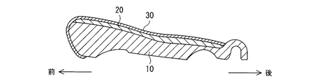
また、第一クッション体10は、図2に示すように、前後方向で前縁部10fと本体部10mとに2分割して構成され、前縁部10fは、本体部10mよりも弾力性が小さく形成されている。ここで、第一クッション体10の本体部10m,前縁部10f及び第二クッション体20の弾力性は、この順で大きく形成されている。以下、本体部10m,前縁部10f及び第二クッション体20の弾力性をそれぞれ、高弾性(高硬度),中弾性(中硬度),低弾性(低反発,低硬度)という。なお、窪み部11は、本体部10mに形成されている。
Moreover, as shown in the broken line of FIG. 3 and FIG. 1, the upper surface of the
Further, as shown in FIG. 2, the
さらに、第一クッション体10の上面は、後方から前方に向かって緩やかに上り傾斜し、前縁部10fが本体部10mよりも厚みをもって形成されている。これにより、着座者の重心は後ろにずれ、体重が、高硬度の本体部10mでしっかりと支持されるようになっている。
また、第二クッション体20は、第一クッション体10と同様に、ポリウレタンフォームからなる発泡体で構成されている。そして、第二クッション体20の上面は略フラットな面形状で形成されている。一方、第二クッション体20の下面は、窪み部11の形状に沿うように形成され、窪み部11と密着するような凸部21を有している。つまり、第二クッション体20の下面は、第一クッション体10の窪み部11を埋めるように、第一クッション体10の上面の形状に沿って形成されている。
Furthermore, the upper surface of the
Moreover, the
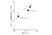
表皮30は、スエード生地を模擬したジャージー(以下、スエード調ジャージーという)で構成されており、図4に示すように、人の着座時の第二クッション体20の沈み込みに追従して伸びる伸び率と、着座した人が前方に滑らない滑り角度(グリップ率)とを有している。詳しくは、スエード調ジャージーは、約50%の伸び率と約40°の滑り角度とを有している。なお、滑り角度とは、座面を傾けていった時に座面上に置いた試験片が滑り始める角度であって、シートの滑りやすさ、又は、シートのグリップ力を示す指標の一つである。また、図4には、参考として、様々な生地でできた表皮の伸び率と滑り角度とを示している。
The
ここで、表皮30は、第二クッション体20の上面及び第一クッション体10の側面を被覆するように形成されているが、少なくとも、第二クッション体20の上面のみを密着して被覆するように形成されていれば良い。つまり、座席1のフラット部3のみが表皮30で被覆されていれば良い。このとき、表皮30を、スエード調ジャージーと他の適宜の生地とが一体に縫合されたものとし、第一クッション体10の側面は、他の適宜の生地で被覆されるようにする。
Here, the
また、ここでは、表皮30として、スエード調ジャージーを選定し、上述のように、伸び率は約50%、且つ、滑り角度は約40°に設定されているが、選定される生地はこれに限定されるものではなく、第二クッション体20の沈み込みに追従して伸びる伸び率と着座した人が前方に滑らない程度の滑り角度とをバランス良く満たしている生地であれば良い。なお、特に、第二クッション体20の沈み込みに追従するためには、生地は30%以上の伸び率が必要であることが、本発明者の実験によって確認されており、つまりは、伸び率と滑り角度とが、図4の円で囲んだ範囲程度に収まる生地であれば良く、表皮30として、例えばバーチニットを選定しても良い。
Here, suede-like jersey is selected as the
<成型方法>
以下、このような座席用クッション構造の成型方法について説明する。
まず最初に、図5に示すように、上型41と下型42とからなる一対の金型を用意する。この上型41と下型42とは、第一クッション体10の本体部10mを成型するための金型であって、上型41と下型42とを閉じて形成される空間43の形状は、本体部10mの立体形状に相当するようになっている。詳述すると、上型41の内面41aは本体部10mの底面形状に相当する形状を形作られている。また、下型42の内面42aは、その表面上で本体部10mの上面が成型されるため、窪み部11を成型するための突出部42bを有して形成されている。
<Molding method>
Hereinafter, a method for forming such a cushion structure for a seat will be described.
First, as shown in FIG. 5, a pair of molds including an
そして、図6に示すように、下型42内に、高弾性の発泡体になるように調整配合されたポリウレタンフォームからなる液状発泡性混合物51を投入し、上型41を閉じて発泡させることで、本体部10mを成型する。また、同様の手法により、第一クッション体10の前縁部10fを成型する。なお、このとき、金型(図示略)の内部には、中弾性の発泡体になるように調整配合されたポリウレタンフォームからなる液状発泡性混合物を投入する。そして、このようにして成型された本体部10mと前縁部10fとを接着し、異硬度の第一クッション体10が成型される(第1工程)。
Then, as shown in FIG. 6, a liquid
次に、図7に示すように、成型された第一クッション体10の上面の全領域に、例えばスプレー方式によりポリウレタンフォームからなる液状発泡性混合物52を投入し、積層する(第2工程)。液状発泡性混合物52は、低弾性の発泡体になるように調整配合されている。
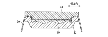
そして、図8に示すように、液状発泡性混合物52のガス発泡は終了しているが、粘弾性流動状態にある反応過程で、液状発泡性混合物52の上面及び第一クッション体10の側面を覆うように表皮30を配置し、第一クッション体10の上方から加圧型44を下降させて、表皮30及び液状発泡性混合物52を、加圧型44と第一クッション体10とで加圧圧縮する(第3工程)。
Next, as shown in FIG. 7, the liquid
And as shown in FIG. 8, although the gas foaming of the liquid
ポリウレタンフォーム等の発泡樹脂は、その液状発泡性混合物が反応して発泡成型が完了すると、安定し且つ弾性特性に優れた発泡体となり、これを加圧圧縮しても簡単に変形することはない。
しかし、反応過程においては非常に不安定な状態であり、ガス反応が終了した後一定時間内では、まだ流動性が残り、外力を作用させることで容易に変形させることができる状態(粘弾性流動状態)にある。そのため、この流動性のあるときに、別の発泡体,繊維などの素材と一体に加圧すると、別の発泡体の中や繊維の組織の一部に入り込み、その別の発泡体や繊維が液状発泡性混合物から形成された発泡体上に固着し、一体的となる。また、液状発泡性混合物の加圧圧縮率を変化させると、圧縮率の高いところでは硬く、低いところでは柔らかな発泡体となる。
When foamed resin such as polyurethane foam reacts with the liquid foamable mixture to complete foam molding, it becomes a foam with stable and excellent elastic properties, and it does not deform easily even if it is compressed with pressure. .
However, it is a very unstable state in the reaction process, and within a certain time after the gas reaction is completed, the fluidity still remains and can be easily deformed by applying external force (viscoelastic flow State). Therefore, when this fluidity is applied together with a material such as another foam or fiber, it enters into another foam or part of the fiber structure, and the other foam or fiber is It adheres and becomes integral on the foam formed from the liquid foamable mixture. Further, when the compression ratio of the liquid foamable mixture is changed, the foam becomes hard at a high compression ratio and soft at a low compression ratio.
したがって、液状発泡性混合物52を固体状態に移行させると、所望の弾力性をもつ第二クッション体20が成型されるとともに、その上側に表皮30が、その下側に第一クッション体10が一体となって固着し、本発明の座席用クッション構造が完成する。
<作用・効果>
本発明の第1実施形態にかかる座席用クッション構造は上述のように構成されているので、以下のような作用・効果がある。
Therefore, when the liquid
<Action and effect>
The seat cushion structure according to the first embodiment of the present invention is configured as described above, and thus has the following operations and effects.
第一クッション体10と第二クッション体20との2層クッション構造で座席1を構成し、さらに、着座時の体重を主に支える坐骨が位置する部分において、比較的硬い第一クッション体10の上面に窪み部11を形成するので、坐骨が位置する部分の第一クッション体10の厚みを薄くすることができる。
そして、比較的柔らかな第二クッション体の凸部21が、窪み部11に嵌合し窪み部11を埋めるので、坐骨が位置する部分の第二クッション体20の厚みを厚くすることができる。
The
And since the
したがって、坐骨が位置する部分の座席1の弾力性が比較的小さくなり、座席1に着座した人の座圧(座面圧力)を分散し、疲労を良好に軽減することができる。
この座圧分散の効果の実証について、図9(a),(b)及び図10(a),(b)を用いて説明する。
図9(a),(b)及び図10(a),(b)は、6軸振動加振機を用いて、東名高速道路を2時間走行した状況設定において、被験者7名で平均した座圧分布の測定結果を示している。
Therefore, the elasticity of the
The demonstration of the effect of the seat pressure dispersion will be described with reference to FIGS. 9 (a) and 9 (b) and FIGS. 10 (a) and 10 (b).
FIGS. 9 (a), 9 (b) and 10 (a), 10 (b) show the seats averaged by 7 subjects in a situation setting in which a 6-axis vibration exciter was used for 2 hours on the Tomei Expressway. The measurement result of pressure distribution is shown.
図9(a)に示すように、本発明の座席用クッション構造で形成された座席(以下、単に本座席という)に着座した場合では、着座直後は、座圧のピーク圧が95g/cm2となっている。これは、図9(b)に示すように、従来の座席用クッション構造で形成された座席(以下、単に従来座席という)に着座した場合の119g/cm2というピーク圧よりも小さい。 As shown in FIG. 9 (a), when seated on a seat (hereinafter simply referred to as the main seat) formed of the seat cushion structure of the present invention, the seat pressure peak pressure is 95 g / cm 2 immediately after seating. It has become. As shown in FIG. 9B, this is smaller than the peak pressure of 119 g / cm 2 when seated on a seat formed of a conventional seat cushion structure (hereinafter simply referred to as a conventional seat).
また、本座席に着座した場合では、図10(a)に示すように、試験後(2時間走行後)は、ピーク圧が125g/cm2であるのに対し、従来座席に着座した場合では、図10(b)に示すように、ピーク圧が142g/cm2である。
なお、ここでいう従来座席とは、図17に示す、窪み部を有していない2層クッション構造で形成された座席を指している。また、表皮として、図4に黒い四角で示すシンフォニットを使用している。
When seated on the main seat, as shown in FIG. 10 (a), the peak pressure after the test (after running for 2 hours) is 125 g / cm 2 , whereas when seated on the conventional seat, As shown in FIG. 10B, the peak pressure is 142 g / cm 2 .
In addition, the conventional seat here refers to the seat formed with the two-layer cushion structure which does not have a hollow part shown in FIG. In addition, a symphony shown by a black square in FIG. 4 is used as the skin.
したがって、従来座席に比べて、本座席に着座した着座者の座圧は分散されていることが分かる。
また、疲労の効果の実証について、図11及び図12を用いて説明する。
疲労評価は、上記の走行試験の被験者7名に対する聞き取り調査によって行なった。
つまり、被験者7名に、試験開始から5〜10分毎(具体的には、5,10,15,25,30,40,45,55,60,65,70,75,85,90,100,105,115,120,125分後)に計19回、図11に示すように、被験者が感じた臀部及び腰の疲労度を、「1;全く疲れてない、2;ほんの少し疲れた、3;やや疲れた、4;疲れた、5;かなり疲れた、6;たいへん疲れた、7;極度に疲れた」の7段階で評価してもらった。そして、被験者毎に、各回の数値を全19回分積算して、疲労度とした。
Therefore, it can be seen that the seating pressure of the seated person seated on the main seat is distributed as compared with the conventional seat.
Further, demonstration of the effect of fatigue will be described with reference to FIGS. 11 and 12.
Fatigue evaluation was conducted by interview with seven subjects in the above running test.
That is, 7 subjects are asked every 5-10 minutes from the start of the test (specifically, 5, 10, 15, 25, 30, 40, 45, 55, 60, 65, 70, 75, 85, 90, 100). , 105, 115, 120, 125 minutes) 19 times in total, as shown in FIG. 11, the fatigue level of the buttocks and lower back felt by the test subject was expressed as “1; not tired at all, 2; Somewhat tired, 4; tired, 5; quite tired, 6; very tired, 7; extremely tired. " Then, for each subject, the numbers of each time were integrated for a total of 19 times to obtain the degree of fatigue.
すると、図12に示すように、従来座席に着座した場合(点t1の場合)に比べて、本座席1に着座した場合(点P1の場合)は、疲労度が減少した。なお、図12の縦軸は被験者7名の疲労度の平均値を示しているとともに、横軸は座圧を示している。
つまり、疲労度は、7〜133の範囲の値をとり、標準的に疲れを感じた場合では、76の値(標準疲労値)をとることになるが、表皮30としてスエード調ジャージーを使用した本座席1に着座した被験者の疲労度の値は、標準疲労値よりも減少した。
Then, as shown in FIG. 12, the degree of fatigue decreased when seated on the main seat 1 (in the case of point P 1 ) compared to when seated in the conventional seat (in the case of point t 1 ). In addition, while the vertical axis | shaft of FIG. 12 has shown the average value of the fatigue level of seven test subjects, the horizontal axis has shown the seat pressure.
That is, the degree of fatigue takes a value in the range of 7 to 133, and when it feels tired normally, it takes a value of 76 (standard fatigue value), but suede-like jersey is used as the
したがって、従来座席に比べて、本座席1に着座すれば、着座者の疲労を良好に軽減できることが分かる。
ここで、表皮30に係る効果をみるために、本座席用クッション構造の表皮30にバーチニットを使用した場合を、図12に点P2で示す。バーチニットを使用した本座席用クッション構造の場合でも、従来座席に比べて、疲労度は軽減した。しかしながら、表皮30をスエード調ジャージーで構成した方が、人の着座時の第二クッション体20の沈み込みに追従して伸び、第一クッション体10及び第二クッション体20の弾力性を座圧に良好に反映することができる。また、着座した人が前方により滑らない滑り角度を有し、着座した人の前ずれを防止し、安定して着座させ、疲労をより軽減することができる。
Therefore, it can be seen that the seated person's fatigue can be satisfactorily reduced by sitting on the
Here, in order to see the effect of the
また、座席1の前縁の弾力性が比較的小さくなるので、第一クッション体10の本体部10mによって着座者の体重を十分に支えながら、大腿部が座席1によって圧迫されることを軽減することができる。
これは、特に、自動車等の車両の運転席に本発明の座席用クッション構造を適用した場合、車両走行にかかる振動が足から全身に伝わるが、柔らかな前縁部10fが振動を吸収し、全身への振動の伝達を抑制して、ドライバーの疲労を軽減することができる。また、大腿部が座席1によって圧迫され難いので、アクセルペダルやブレーキペダルの踏み込み操作に係る疲労軽減にも効果的である。
In addition, since the elasticity of the front edge of the
This is particularly true when the seat cushion structure of the present invention is applied to the driver's seat of a vehicle such as an automobile, and the vibration applied to the vehicle travels from the foot to the whole body, but the soft
さらに、本座席1の振動特性について測定した結果、図13に示すように、本座席1の振動ピークは、従来座席の振動ピークに比べて、人体の内臓に影響があるとされる6Hzから遠ざかり、且つ、6Hzでの振幅が小さくなっているという利点があることが確認された。
[第2実施形態]
次に、図14を参照して、本発明の第2実施形態を説明する。
Furthermore, as a result of measuring the vibration characteristics of the
[Second Embodiment]
Next, a second embodiment of the present invention will be described with reference to FIG.
図14は、本発明の第2実施形態に係る座席用クッション構造の幅方向断面図である。なお、第1実施形態の説明で用いた図3を適宜流用して説明するとともに、第1実施形態のものと同じ部材等は、第1実施形態の説明と同一の符号で説明する。
<構成>
第2実施形態は、第1実施形態に対して、第二クッション体の凸部に係る構造が異なるものである。
FIG. 14 is a cross-sectional view in the width direction of the cushion structure for a seat according to the second embodiment of the present invention. In addition, while using FIG. 3 used in description of 1st Embodiment suitably, it demonstrates, and the member same as the thing of 1st Embodiment is demonstrated with the same code | symbol as description of 1st Embodiment.
<Configuration>
2nd Embodiment differs in the structure which concerns on the convex part of a 2nd cushion body with respect to 1st Embodiment.
第2実施形態の座席用クッション構造は、第1実施形態と同様に、図3に示すように、着座者の臀部を包み込むように隆起部2とフラット部3とを有する座席1に適用されている。
座席用クッション構造は、図14に示すように、窪み部11を有する第一クッション体10と、第一クッション体10の上面に積層して配置され、第一クッション体10よりも弾力性の小さい第二クッション体60と、第二クッション体60の上面及び第一クッション体10の側面を密着して覆う表皮30とを備えている。
As in the first embodiment, the seat cushion structure of the second embodiment is applied to a
As shown in FIG. 14, the seat cushion structure is disposed on the upper surface of the
さらに、第2実施形態の特徴として、窪み部11に嵌合して、第一クッション体10の上面と第二クッション体60の下面とに挟まれ、第二クッション体60よりも弾力性の小さいクッション片70を備えている。
従って、第2実施形態では、クッション片70が第二クッション体60の凸部を形成するものである。
<作用・効果>
本発明の第2実施形態にかかる座席用クッション構造は上述のように構成されているので、第1実施形態で奏した上述の効果に加え、以下のような作用・効果がある。
Further, as a feature of the second embodiment, it fits into the
Therefore, in the second embodiment, the
<Action and effect>
Since the seat cushion structure according to the second embodiment of the present invention is configured as described above, in addition to the effects described in the first embodiment, the following functions and effects are obtained.
第二クッション体60よりも柔らかなクッション片70によって、坐骨が位置する部分の座席1の弾力性がさらに小さくなり、座席1に着座した人の座圧をより分散し、疲労を良好に軽減することができる。
また、クッション片70の弾力性を変更することで、座圧の分散を容易に調整することができる。
The
Further, by changing the elasticity of the
[その他]
以上、本発明の実施形態について説明したが、本発明は、上記実施形態に限定されず、本発明の趣旨を逸脱しない範囲で種々変形することが可能である。
例えば、上記実施形態において、第一クッション体10及び第二クッション体20は、ポリウレタンフォームからなる発泡体で構成されているが、ポリウレアフォーム等の他の発泡樹脂からなる発泡体に代えても良い。
[Others]
As mentioned above, although embodiment of this invention was described, this invention is not limited to the said embodiment, A various deformation | transformation is possible in the range which does not deviate from the meaning of this invention.
For example, in the said embodiment, although the
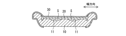
また、上記実施形態において、第一クッション体10に設けた窪み部11を第二クッション体20やクッション片70で埋めたが、図15に示すように、窪み部11を特に埋めることなく、第一クッション体10の上面と第二クッション体20の下面とで囲繞される中空空間(空洞)Sになるように成型しても良い。このような場合でも、坐骨が位置する部分の座席1の弾力性がさらに小さくなり、座席1に着座した人の座圧をより分散し、疲労を良好に軽減することができる。
Moreover, in the said embodiment, although the
また、上記実施形態において、第一クッション体10は、本体部10mと前縁部10fとで硬度が異なるように成型したが、図16に示すように一様な硬度で成型しても良いし、さらに細かく硬度が異なるように成型しても良い。
また、上記第1実施形態において、クッション構造の成型方法について説明したが、クッション構造の成型方法はこれに限定されない。
Moreover, in the said embodiment, although the
Moreover, in the said 1st Embodiment, although the molding method of the cushion structure was demonstrated, the molding method of a cushion structure is not limited to this.
上記第1実施形態では、第3工程として、第一クッション体10の上方から加圧型44を下降させて、表皮30及び液状発泡性混合物52を、加圧型44と第一クッション体10とで加圧圧縮するようにしたが、例えば、加圧型44に代えて、複数の吸引孔をその加圧面に有するとともに、その内部空間に外部の真空排気系が接続される真空加圧型(図示略)を備え、真空加圧型の内部空間を真空にし、加圧面に表皮30を吸引させた状態で、表皮30及び液状発泡性混合物52を、真空加圧型と第一クッション体10とで加圧圧縮するようにしても良い。
In the first embodiment, as the third step, the
また、第1工程及び第2工程として、異硬度の発泡体になるように調整配合されたポリウレタンフォームからなる液状発泡性混合物51,52を充填したが、例えば、液状発泡性混合物51,52の成分配合率は一律とし、加圧圧縮率を変えることのみにより、クッション体10,20の硬度を変えるようにしても良い。
また、上記各実施形態では、本発明の座席用クッション構造を自動車等の車両の座席に適用した場合について説明したが、本発明の座席用クッション構造は、種々の家具用座席等にも適用することが可能である。
Further, as the first step and the second step, the liquid
In each of the above embodiments, the case where the seat cushion structure of the present invention is applied to a vehicle seat such as an automobile has been described. However, the seat cushion structure of the present invention is also applied to various furniture seats and the like. It is possible.
1 座席
2 隆起部
3 フラット部
10 第一クッション体
10f 前縁部
10m 本体部
10s 側部
11 窪み部
20 第二クッション体
21 凸部
30 表皮
41 上型
42 下型
43 空間
51,52 液状発泡性混合物
60 第二クッション体
70 クッション片
100 クッション体
101 第一クッション体
102 第二クッション体
110 表皮材
DESCRIPTION OF
Claims (4)
ベースとなる第一クッション体と、
該第一クッション体の上面に積層して配置され、該第一クッション体よりも弾力性の小さい第二クッション体とを備え、
該第一クッション体の上面は、着座した人の坐骨が位置する部分において、下方に向かって緩やかに湾曲して窪む窪み部を有し、
該第二クッション体の下面は、該窪み部の形状に沿うように形成されるとともに該窪み部と密着するような凸部を備え、
該第一クッション体は、前後方向で前縁部と本体部とに2分割して構成するとともに、
該本体部、該前縁部及び該第二クッション体の順に高弾性、中弾性及び低弾性と弾力性が形成されている
ことを特徴とする、座席用クッション構造。 A cushion structure for a seat on which a person sits,
A first cushion body as a base;
A second cushion body that is disposed on the upper surface of the first cushion body and is less elastic than the first cushion body;
The upper surface of the first cushion body has a hollow portion that is gently curved downward and recessed in a portion where the sciatic bone of a seated person is located ,
The lower surface of the second cushion body is formed so as to conform to the shape of the recess, and has a convex portion that is in close contact with the recess.
The first cushion body is divided into two parts, a front edge portion and a main body portion in the front-rear direction,
A seat cushion structure characterized by high elasticity, medium elasticity, low elasticity and elasticity being formed in the order of the main body, the front edge, and the second cushion body .
該第二クッション体よりも弾力性の小さいクッション片を備えた
ことを特徴とする、請求項1記載の座席用クッション構造。 Fitted to the recess and sandwiched between the upper surface of the first cushion body and the lower surface of the second cushion body,
The cushion structure for a seat according to claim 1, further comprising a cushion piece that is less elastic than the second cushion body.
該表皮は、伸び率30%以上を有する生地で構成される
ことを特徴とする、請求項1または2に記載の座席用クッション構造。 An epidermis that adheres and covers the upper surface of the second cushion body;
The cushion structure for a seat according to claim 1 or 2, wherein the skin is made of a cloth having an elongation rate of 30% or more.
ことを特徴とする、請求項3記載の座席用クッション構造。 The seat cushion structure according to claim 3 , wherein the skin is a jersey simulating a suede fabric .
Priority Applications (1)
| Application Number | Priority Date | Filing Date | Title |
|---|---|---|---|
| JP2007153017A JP5038784B2 (en) | 2007-06-08 | 2007-06-08 | Seat cushion structure |
Applications Claiming Priority (1)
| Application Number | Priority Date | Filing Date | Title |
|---|---|---|---|
| JP2007153017A JP5038784B2 (en) | 2007-06-08 | 2007-06-08 | Seat cushion structure |
Publications (2)
| Publication Number | Publication Date |
|---|---|
| JP2008302085A JP2008302085A (en) | 2008-12-18 |
| JP5038784B2 true JP5038784B2 (en) | 2012-10-03 |
Family
ID=40231315
Family Applications (1)
| Application Number | Title | Priority Date | Filing Date |
|---|---|---|---|
| JP2007153017A Active JP5038784B2 (en) | 2007-06-08 | 2007-06-08 | Seat cushion structure |
Country Status (1)
| Country | Link |
|---|---|
| JP (1) | JP5038784B2 (en) |
Families Citing this family (4)
| Publication number | Priority date | Publication date | Assignee | Title |
|---|---|---|---|---|
| CA2841871A1 (en) * | 2011-07-14 | 2013-01-17 | Proprietect L.P. | Foam seat element, and process and mold for producing same |
| JP6709679B2 (en) * | 2016-05-11 | 2020-06-17 | 株式会社イノアックコーポレーション | Cushion pad for vehicle and manufacturing method thereof |
| CN108819807B (en) * | 2018-07-18 | 2023-08-18 | 威马智慧出行科技(上海)有限公司 | Seat cushion and automobile seat |
| JP7369135B2 (en) * | 2018-09-21 | 2023-10-25 | 株式会社アーケム | cushion pad |
Family Cites Families (6)
| Publication number | Priority date | Publication date | Assignee | Title |
|---|---|---|---|---|
| JPS4119057Y1 (en) * | 1964-04-27 | 1966-09-06 | ||
| JPS6391051A (en) * | 1986-10-07 | 1988-04-21 | Nobuo Komori | Draining apparatus for food |
| JPH0423459A (en) * | 1990-05-18 | 1992-01-27 | Hitachi Ltd | Semiconductor device and manufacture thereof, and lead frame used therefor |
| JP3796558B2 (en) * | 1997-08-25 | 2006-07-12 | テイ・エス テック株式会社 | Manufacturing method of automobile seat back |
| ES2341957T3 (en) * | 2003-06-30 | 2010-06-30 | The Way To Win Limited | SEAT PART OF A SEAT. |
| JP2005132085A (en) * | 2003-10-31 | 2005-05-26 | Toyo Quality One Corp | Molded pad for outer skin-bonded molding, and outer skin-bonded molding |
-
2007
- 2007-06-08 JP JP2007153017A patent/JP5038784B2/en active Active
Also Published As
| Publication number | Publication date |
|---|---|
| JP2008302085A (en) | 2008-12-18 |
Similar Documents
| Publication | Publication Date | Title |
|---|---|---|
| JP5555674B2 (en) | Vehicle seat back pad and vehicle seat | |
| JP5387174B2 (en) | Vehicle seat | |
| JP5955617B2 (en) | Seat cushion pad | |
| CN101128138A (en) | Seat cushion pad for vehicle, seat back pad for vehicle, and seat for vehicle | |
| JP5606845B2 (en) | Manufacturing method of seat cushion pad | |
| JP5038784B2 (en) | Seat cushion structure | |
| JP2014205490A (en) | Seat cushion pad | |
| JPH1033297A (en) | Seat | |
| JP4797379B2 (en) | Vehicle seat cushion pad, vehicle seat back pad, and vehicle seat | |
| JP3463182B2 (en) | Vehicle seat | |
| JP4738792B2 (en) | Seat pad | |
| JP2010184085A (en) | Seat pad for vehicle | |
| JP3772612B2 (en) | Sheet | |
| JP4196744B2 (en) | Vehicle seat | |
| JP2002065409A (en) | Seat cushion pad | |
| JP2004147979A (en) | Cushion material for vehicle sheet | |
| JP4496059B2 (en) | Seat pad | |
| JP3122789U (en) | Tyler | |
| JP4133864B2 (en) | Cushion body for vehicle seat | |
| JP3948989B2 (en) | Cushion body | |
| JPH08150976A (en) | Seat of motorcycle | |
| JP5601011B2 (en) | Seat, cushion for seat, and method for manufacturing the same | |
| JP2005211251A (en) | Seat cushion pad for vehicle | |
| JP2005021671A (en) | Seat cushion pad for vehicle | |
| JP2017070633A (en) | Seat pad for vehicle and seat for vehicle |
Legal Events
| Date | Code | Title | Description |
|---|---|---|---|
| A621 | Written request for application examination |
Free format text: JAPANESE INTERMEDIATE CODE: A621 Effective date: 20090703 |
|
| A977 | Report on retrieval |
Free format text: JAPANESE INTERMEDIATE CODE: A971007 Effective date: 20111202 |
|
| A131 | Notification of reasons for refusal |
Free format text: JAPANESE INTERMEDIATE CODE: A131 Effective date: 20111213 |
|
| A521 | Request for written amendment filed |
Free format text: JAPANESE INTERMEDIATE CODE: A523 Effective date: 20120213 |
|
| TRDD | Decision of grant or rejection written | ||
| A01 | Written decision to grant a patent or to grant a registration (utility model) |
Free format text: JAPANESE INTERMEDIATE CODE: A01 Effective date: 20120626 |
|
| A01 | Written decision to grant a patent or to grant a registration (utility model) |
Free format text: JAPANESE INTERMEDIATE CODE: A01 |
|
| A61 | First payment of annual fees (during grant procedure) |
Free format text: JAPANESE INTERMEDIATE CODE: A61 Effective date: 20120706 |
|
| FPAY | Renewal fee payment (event date is renewal date of database) |
Free format text: PAYMENT UNTIL: 20150713 Year of fee payment: 3 |
|
| R150 | Certificate of patent or registration of utility model |
Ref document number: 5038784 Country of ref document: JP Free format text: JAPANESE INTERMEDIATE CODE: R150 Free format text: JAPANESE INTERMEDIATE CODE: R150 |
|
| R250 | Receipt of annual fees |
Free format text: JAPANESE INTERMEDIATE CODE: R250 |
|
| R250 | Receipt of annual fees |
Free format text: JAPANESE INTERMEDIATE CODE: R250 |
|
| R250 | Receipt of annual fees |
Free format text: JAPANESE INTERMEDIATE CODE: R250 |
|
| R250 | Receipt of annual fees |
Free format text: JAPANESE INTERMEDIATE CODE: R250 |
|
| R250 | Receipt of annual fees |
Free format text: JAPANESE INTERMEDIATE CODE: R250 |
|
| R250 | Receipt of annual fees |
Free format text: JAPANESE INTERMEDIATE CODE: R250 |
|
| S531 | Written request for registration of change of domicile |
Free format text: JAPANESE INTERMEDIATE CODE: R313531 |
|
| R350 | Written notification of registration of transfer |
Free format text: JAPANESE INTERMEDIATE CODE: R350 |
|
| R250 | Receipt of annual fees |
Free format text: JAPANESE INTERMEDIATE CODE: R250 |
|
| R250 | Receipt of annual fees |
Free format text: JAPANESE INTERMEDIATE CODE: R250 |
|
| R250 | Receipt of annual fees |
Free format text: JAPANESE INTERMEDIATE CODE: R250 |
|
| R250 | Receipt of annual fees |
Free format text: JAPANESE INTERMEDIATE CODE: R250 |