JP5037677B2 - Hip fracture device with barrel and end cap for load control - Google Patents
Hip fracture device with barrel and end cap for load control Download PDFInfo
- Publication number
- JP5037677B2 JP5037677B2 JP2010503388A JP2010503388A JP5037677B2 JP 5037677 B2 JP5037677 B2 JP 5037677B2 JP 2010503388 A JP2010503388 A JP 2010503388A JP 2010503388 A JP2010503388 A JP 2010503388A JP 5037677 B2 JP5037677 B2 JP 5037677B2
- Authority
- JP
- Japan
- Prior art keywords
- screw
- end cap
- friction pin
- head
- barrel
- Prior art date
- Legal status (The legal status is an assumption and is not a legal conclusion. Google has not performed a legal analysis and makes no representation as to the accuracy of the status listed.)
- Active
Links
Images


Classifications
-
- A—HUMAN NECESSITIES
- A61—MEDICAL OR VETERINARY SCIENCE; HYGIENE
- A61B—DIAGNOSIS; SURGERY; IDENTIFICATION
- A61B17/00—Surgical instruments, devices or methods, e.g. tourniquets
- A61B17/56—Surgical instruments or methods for treatment of bones or joints; Devices specially adapted therefor
- A61B17/58—Surgical instruments or methods for treatment of bones or joints; Devices specially adapted therefor for osteosynthesis, e.g. bone plates, screws, setting implements or the like
- A61B17/68—Internal fixation devices, including fasteners and spinal fixators, even if a part thereof projects from the skin
- A61B17/84—Fasteners therefor or fasteners being internal fixation devices
- A61B17/86—Pins or screws or threaded wires; nuts therefor
- A61B17/8685—Pins or screws or threaded wires; nuts therefor comprising multiple separate parts
-
- A—HUMAN NECESSITIES
- A61—MEDICAL OR VETERINARY SCIENCE; HYGIENE
- A61B—DIAGNOSIS; SURGERY; IDENTIFICATION
- A61B17/00—Surgical instruments, devices or methods, e.g. tourniquets
- A61B17/56—Surgical instruments or methods for treatment of bones or joints; Devices specially adapted therefor
- A61B17/58—Surgical instruments or methods for treatment of bones or joints; Devices specially adapted therefor for osteosynthesis, e.g. bone plates, screws, setting implements or the like
- A61B17/68—Internal fixation devices, including fasteners and spinal fixators, even if a part thereof projects from the skin
- A61B17/74—Devices for the head or neck or trochanter of the femur
- A61B17/742—Devices for the head or neck or trochanter of the femur having one or more longitudinal elements oriented along or parallel to the axis of the neck
- A61B17/746—Devices for the head or neck or trochanter of the femur having one or more longitudinal elements oriented along or parallel to the axis of the neck the longitudinal elements coupled to a plate opposite the femoral head
-
- A—HUMAN NECESSITIES
- A61—MEDICAL OR VETERINARY SCIENCE; HYGIENE
- A61B—DIAGNOSIS; SURGERY; IDENTIFICATION
- A61B17/00—Surgical instruments, devices or methods, e.g. tourniquets
- A61B2017/00831—Material properties
- A61B2017/00858—Material properties high friction, non-slip
Description
この出願は、2007年4月19日に出願された米国仮出願第60/925,399号の出願日の利益を主張し、その開示がここに参照として引用される。 This application claims the benefit of the filing date of US Provisional Application No. 60 / 925,399, filed Apr. 19, 2007, the disclosure of which is hereby incorporated by reference.
本発明は、概ね、大腿骨の頚部と転子間領域とを含む近位大腿骨の骨折の治療のための装置及び方法に関する。 The present invention relates generally to an apparatus and method for treatment of proximal femoral fractures including the femoral neck and the intertrochanteric region.
図1を参照すると、大腿骨(femur)1は、大腿骨(thigh bone)としても既知であり、一般的には、股関節(hip)から膝関節(knee)まで延びる細長い骨幹(shaft)を含む。骨幹3の近位端部は、頭部5と、頚部7と、より大きい転子8と、より小さい転子9とを含む。大腿骨骨折の内部固定は、一般的には、最も一般的な整形外科手術の1つである。大腿骨の近位部分の骨折(股関節骨折)は、一般的には、大腿骨頚部骨折と、転子間骨折とを含む。骨の頚部内に延びる大腿骨の骨折は、しばしば、ネジを用いて処置され、ネジは、大腿骨頭部内に螺入し、骨幹3の横側(側面)のプレートまで、大腿骨頚部軸A−Aと概ね平行に延びている。
Referring to FIG. 1, a femur 1, also known as a thigh bone, generally includes an elongated shaft extending from the hip to the knee. . The proximal end of the
大腿骨頚部骨折のための従来的な骨折固定システムは、米国特許第3,107,666号(第666号特許)中に開示されている。第666特許の骨折固定システムは、スリープと、スリーブ内に挿入されるネイルとを有する。プラスチックリングが、スリーブとネイルとの間に配置される。プラスチックリングは、スリーブの内部円筒形表面及びネイルの外表面と摩擦係合する。摩擦は、スリーブとネイルとの間の相対運動に対する抵抗を生み出す。しかしながら、システムに対して作用する力が閾値を超えるや否や、ネイルとスリープとの間の相対運動が許容される。 A conventional fracture fixation system for femoral neck fracture is disclosed in US Pat. No. 3,107,666 (the '666 patent). The fracture fixation system of the '666 patent has a sleep and a nail inserted into the sleeve. A plastic ring is disposed between the sleeve and the nail. The plastic ring frictionally engages the inner cylindrical surface of the sleeve and the outer surface of the nail. Friction creates resistance to relative movement between the sleeve and the nail. However, as soon as the force acting on the system exceeds the threshold, relative movement between the nail and the sleep is allowed.
他の従来的なネジ及びプレートシステムは、典型的には、骨折に亘って静的静圧縮力を適用する。患者による装填に応答してネジがその軸に沿って進行するのを許容することは、骨折を治癒するために強い骨の成長をさらに促進することが分かった。この種類のネジは、動的圧縮ネジとして既知であり、軸方向運動をもたらしながら、骨折に亘る角回転又は横方向運動を防止しなければならない。動的圧縮ネジの1つの欠点は、進行が適切に制限されないならば、大腿骨の頚部は望ましくなく短くされ得ることである。 Other conventional screw and plate systems typically apply a static static compression force across the fracture. It has been found that allowing the screw to advance along its axis in response to loading by the patient further promotes strong bone growth to heal the fracture. This type of screw, known as a dynamic compression screw, must prevent angular rotation or lateral movement across the fracture while providing axial movement. One disadvantage of dynamic compression screws is that the femoral neck can be undesirably shortened if progression is not properly limited.
従って、軸方向運動の程度(距離限定増強)を調節可能に制御し、進行に抗する力(荷重制御増強)を調節可能に提供することが望ましい。もし抵抗力が進行の程度と共に増大するならば特に有利である。 Therefore, it is desirable to adjustably control the degree of axial movement (distance limited enhancement) and to adjust the force against progression (load control enhancement). It is particularly advantageous if the resistance increases with the degree of progression.
ここで使用される場合、人体の骨又は他の部分に言及するときには、「近位」という用語は、心臓により近いことを意味し、「遠位」という用語は、心臓からより離れていることを意味する。「下方」という用語は、足に向かうことを意味し、「上方」という用語は、頭部に向かうことを意味する。「前側」という用語は、人体又は顔の前方部分に向かうことを意味し、「後側」という用語は、人体の背部に向かうことを意味する。「内側」という用語は、人体の正中線に向かうことを意味し、「外側」という用語は、人体の正中線から離れることを意味する。 As used herein, when referring to bones or other parts of the human body, the term “proximal” means closer to the heart, and the term “distal” is farther from the heart. Means. The term “down” means toward the foot and the term “up” means toward the head. The term “front” means toward the front of the human body or face, and the term “rear” means toward the back of the human body. The term “inside” means toward the midline of the human body, and the term “outside” means away from the midline of the human body.
本発明は、距離限定増強、荷重制御増強、及び、距離限定増強と荷重制御増強との組み合わせを許容する股関節骨折装置、並びに、これらの装置を使用する方法を提供することによって、上述された必要を満たす。 The present invention provides a hip fracture device that allows distance limitation enhancement, load control enhancement, and a combination of distance limitation enhancement and load control enhancement, as well as the need described above by providing a method of using these devices. Meet.
股関節骨折装置は、プレート及びネジ組立体を有する。ネジ組立体内のモジュラ構成部品の交換によって、軸方向移動及び移動に抗する力の程度は、相互動作的に調節可能である。 The hip fracture device has a plate and screw assembly. By exchanging modular components within the screw assembly, the degree of axial movement and the resistance to movement can be adjusted interactively.
本発明の1つの特徴において、股関節骨折装置は、バレル内でのネジの軸方向移動の程度を可変に制限しながら、ネジをバレルと同軸であるよう制約するよう、固定バレルとモジュラエンドキャップを使用する。 In one aspect of the invention, the hip fracture device includes a fixed barrel and a modular end cap to constrain the screw to be coaxial with the barrel while variably limiting the degree of axial movement of the screw within the barrel. use.
本発明の他の特徴では、エンドキャップに取り付けられる摩擦ピンが、荷重制御増強をもたらすために、ネジ内のボアと進行的に係合する。 In another aspect of the invention, a friction pin attached to the end cap progressively engages a bore in the screw to provide increased load control.
本発明の他の特徴において、股関節骨折装置は、ヘッド部とシャフト部とを有するプレートを含む。バレルが、プレートのヘッド部から突出し、ネジがバレル内に挿入される。摩擦ピンが、ネジと摺動可能に接続され、エンドキャップが、プレートのヘッド部に固定される。荷重が骨折装置に加えられるとき、ネジはエンドキャップに向かって摩擦ピンの上を摺動する。摩擦ピンの上でネジをさらに摺動するために必要とされる荷重は、ネジがエンドキャップに向かって摺動するに応じて増分的に増大する。 In another aspect of the invention, the hip fracture device includes a plate having a head portion and a shaft portion. A barrel projects from the head of the plate and a screw is inserted into the barrel. A friction pin is slidably connected to the screw and an end cap is secured to the head portion of the plate. When a load is applied to the fracture device, the screw slides over the friction pin toward the end cap. The load required to further slide the screw over the friction pin increases incrementally as the screw slides toward the end cap.
本発明の他の特徴は、大腿骨の頭部と頚部との間の骨折を修復する方法である。本方法は、ヘッド部とシャフト部とを有するプレートを大腿骨に固定することを含み、プレートは、ヘッド部とシャフト部とに開口を有する。バレルがヘッド部の開口に挿入され、ネジがバレルに挿入される。エンドキャップが、バレルをその中に挿入する開口に挿入され、摩擦ピンが、エンドキャップとネジとの間に挿入される。ネジはエンドキャップに向かって摩擦ピンの上を摺動し得る。摩擦ピンの上でネジをさらに摺動するために必要とされる荷重は、ネジがエンドキャップに向かって摺動するに応じて増分的に増大する。 Another feature of the invention is a method of repairing a fracture between the femoral head and neck. The method includes securing a plate having a head portion and a shaft portion to the femur, the plate having openings in the head portion and the shaft portion. The barrel is inserted into the opening of the head portion, and the screw is inserted into the barrel. An end cap is inserted into the opening into which the barrel is inserted, and a friction pin is inserted between the end cap and the screw. The screw can slide over the friction pin toward the end cap. The load required to further slide the screw over the friction pin increases incrementally as the screw slides toward the end cap.
他の特徴において、本発明は、頭部と頚部との間の骨折を修復するためのキットを提供する。キットは、少なくとも1つのプレートを含み、プレートは、頭部と、シャフト部とを有し、開口が、頭部及びシャフト部に形成される。キットは、頭部の開口への挿入のために構成される少なくとも1つのバレルと、少なくとも2つのネジとを含み、各ネジは、中心ボアを有し、各ボアは、異なる直径を有する。同様に含まれるのは、少なくとも2つの摩擦ピンであり、各摩擦ピンは、ネジの1つの中心ボアの1つの直径と一致する外径を有し、少なくとも2つのエンドキャップを含み、各エンドキャップは、摩擦ピンの1つの直径と一致する第一ボアを有する。 In another aspect, the present invention provides a kit for repairing a fracture between the head and neck. The kit includes at least one plate, the plate having a head portion and a shaft portion, and an opening is formed in the head portion and the shaft portion. The kit includes at least one barrel configured for insertion into the head opening and at least two screws, each screw having a central bore, each bore having a different diameter. Also included are at least two friction pins, each friction pin having an outer diameter that matches one diameter of one central bore of the screw, including at least two end caps, each end cap Has a first bore coinciding with one diameter of the friction pin.
図1を参照すると、股関節骨折装置21は、係止プレート11と、1つ又はそれよりも多くの(好ましくは3つの)ネジ組立体31とを含む。股関節骨折装置21は、骨折、特に、ガーデンIII/IV型骨折を含む大腿骨頚部骨折を固定するために使用され得る。
Referring to FIG. 1, the
係止プレート11は、近位大腿骨の側部に概ね合致し、大腿骨1の転子下の骨幹(シャフト)領域3内の孔を通る少なくとも1つの皮質連結ネジ15によって大腿骨に取り付けられる。連結ネジ15は、プレート11を大腿骨1に取り付ける働きをする。プレート11は、各ネジ組立体31のための1つ又はそれよりも多くの段付きボア17も有する。段付きボア17の大きい直径は、ネジ組立体31を締結するためのネジ山を含む。段付きボア17の小さい直径は、大きい直径及び小さい直径の接合部に肩部19を創成する。各段付きボア17は、ネジ組立体31のそれぞれの軸と整列される。図2は、プレート11Aを示している。プレート11Aは、プレート11の設計の変形であり、スロット13Aを含む。プレート11Aは、プレート11の代わりに使用され得る。案内ワイヤが、スロット13Aを通じて大腿骨1内に挿入され得る。案内ワイヤは、プレート11Aを大腿骨1の表面上で所望の整列に位置付けるために使用され得る。以後に開示される圧縮ネジの実施態様は、骨プレート11Aと共に使用され得る。
The
ネジ組立体31は、股関節ネジ33と、バレル41と、エンドキャップ51と、摩擦ピン61とを含む。摩擦ピンは、バネピンとも呼ばれ得る。少なくとも1つのネジ組立体31が、プレート11と共に、大腿骨頭部5上の荷重に起因する垂直力(法線力)Fによって大腿骨頸部7上に創成されるモーメントを相殺するために表示方向に角安定性をもたらす。ネジ組立体31は、全ての他の方向にも角安定性をもたらす。もし1つよりも多くのネジ組立体31がプレート11に接続されるならば、頭部軸A−Aについての回転安定性が達成される。典型的には、股関節ネジ組立体31は、図示されるように、大腿骨頸部軸A−Aと平行に方向付けられる。
The
股関節ネジ33は、典型的には、ボア37にカニューレ挿入される。非カニューレ挿入版は、遠位端部に盲ボア37を有し得る。ネジ33は、小さい外径を定める中心シャフト34と、ネジの遠位端部に大きい外径を定める外部フランジ38とを有する。フランジ38の内側に形成されているのは、六角ソケット39のような回転機能である。ボアに固定されるのに適したネジ山35が、ネジ33の近位端部に形成され、大腿骨頭部5の海綿骨と係合する。
図3を参照すると、バレル41は、概ね円筒形であり、プレート11内の段付きボア17の小さい直径に対応する外径43を備える。バレル41は、段付きボア17内に滑合(滑り嵌め)し、段部19上に載る。
Referring to FIG. 3, the
バレル41の遠位端部に配置されているのは、外部フランジ49であり、外部フランジは、段付きボア17の大きい直径と滑合し、バレル41がネジ組立体軸に沿って近位方向に移動するのを防止するために肩部19と係合する。バレル41は、大きい直径46と小さい直径47とを備える段付きボア45を有する。小さい直径47は、大きい直径46及び小さい直径47の接合部に肩部48を創成する。小さい直径47は、ネジ33の中心シャフト34と滑合し、肩部48は、ネジ33がネジ組立体軸に沿って近位方向に移動することを制限するために、外部フランジ38と係合する。
Disposed at the distal end of the
頭部52が、エンドキャップ51の遠位部に形成されている。頭部52は、大きい直径53と、プレート11のボア17の噛み合いネジ山との締結のために、大きい直径53上に形成された外部機械加工ネジ山とを含む。頭部52の内側に形成されているのは、六角ソケット59のような回転機能である。エンドキャップ51の近位領域は、バレル41の大きい直径との滑合をもたらす小さい直径56を備えるシャフト55である。シャフト55は、ネジ33がネジ組立体軸に沿って遠位方向に移動するのを制限するために、フランジ38の端部に当接し得る近位端部58を有する。端部58は、盲ボア57を有する。
A
摩擦ピン61は、荷重制御増強のために設けられる。摩擦ピン61は、典型的には、スロット67(図4)を備えるロールピンであり、それは、存在するとき、ボア57内にプレス嵌めされ、ネジ33のボア37と滑り干渉嵌めされる。ボア57は、摩擦ピンを堅く保持するような大きさとされる。ボア57は、図8乃至11と共にさらに記載されるように、ネジ33がネジ組立体軸に沿って遠位方向に移動するのに抗するために制御された摩擦抵抗をもたらす大きさとされる。ネジ組立体31の全ての様々な直径及びボアは、図4に描写されるように、組立体の軸について同心状であり、図4はエンドキャップ51又は六角ソケット39を示していない。様々な同心状の滑合は、ネジ33がその軸に沿ってのみ、即ち、軸A−Aと平行に移動することを可能にする。
The
大腿骨1上での装置21の組立ては、以下の通り進行する。先ず、プレート11が、骨幹3の側方領域で近位大腿骨1に固定される。大腿骨1は、ネジ31及びバレル41の挿入のための大きさとされた孔を穿孔することによって準備される。次に、バレル41が、その最終位置(フランジ49が肩部49に対して位置付けられる位置)がボア17の大きい直径と小さい直径との間に形成されるまで、プレート11のボア17内に挿入される。次に、ネジ33が、バレル41内に挿入され、ネジフランジ38がバレル肩部48に対して位置付けられるまで、骨内に回転される。圧縮ネジ33の幾つかの追加的な回転によって、大腿骨頭部を含む大腿骨頭部骨片が、大腿骨1の遠位骨折表面に対して引っ張られ、骨折が初期的に圧縮される。
The assembly of the
エンドキャップ51及び摩擦ピン61の様々な構造のキットから選択することによって、増強のために必要とされる程度及び力が、手術中のこの時点で外科医によって調節され得る。外科医が、移動を厳格に制限し且つ大腿骨頚部が短くなることを防止するために、骨片の静止係合を望むならば、図5に示されるように、ネジ33の遠位運動を防止するために、より長いシャフト56aを備えるエンドキャップ51aが使用される。ここでは、エンドキャップ51は、ネジ33の端部と接触しており、従って、大腿骨頭部骨片の軸方向移動は許容されない。図6は、ネジ33の距離限定摺動を可能とするために様々な長さのシャフト56を備えるエンドキャップ51がどのように使用され得るかを示している。図6では、エンドキャップ56の端部とネジ33の反対端部との間には空間がある。従って、ネジ33、結果的に、大腿骨頭部骨片は、エンドキャップ56に向かって軸方向に移動し得る。この場合における最大移動距離は、エンドキャップ56の端部とネジ33の反対端部との間の空間と等しい。大腿骨頭部骨片のこの距離限定摺動は、荷重負荷による骨片対抗(fragment opposition)及び術後動的骨折場所圧縮(postoperative dynamic fracture site compression)を許容しながら、大腿骨頸部が過剰に短くなることを制限する。
By selecting from various construction kits of
図7に示されるように、摩擦ピン61が追加されるとき、ネジ組立体31は、ネジ33の荷重制御摺動をもたらす。この摺動は、荷重負荷による大腿骨頭部骨片対抗及び術後動的骨折場所圧縮を許容しながら、骨折場所上の荷重を制限し、荷重に基づく移動距離を制限し、且つ、骨の応力誘導再吸収(stress induced resorption)を防止する。摩擦ピン61及びボア37によって創成される初期摩擦は、患者重量、骨構造、及び、骨折の種類に従った様々な直径を備えるピンのキットから選択することによって変更され得る。よって、より大きい骨を備えるより重い患者は、より多くの摩擦を創成するピンを装着され得る。
As shown in FIG. 7, when the
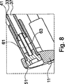
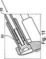
図7に示される股関節装置21は、荷重負荷による骨片付着(fragment apposition)及び術後動的骨折場所圧縮を可能にしながら、骨折場所に対する荷重を制限し且つ骨の応力誘導再吸収を防止するために、大腿骨頭部骨片の荷重制御された摺動をもたらす。制御機構は、摺動距離の増大を伴う抵抗の増大をもたらす。これは、図8乃至11に描写されるように、摺動中にボア37によって係合される摩擦ピン61の進行的により大きい長さによって引き起こされる。ネジ33の摺動は、抵抗が体重誘導力と等しくなるとき或いは距離制限に達するときのいずれかに停止する。
The hip
多数のネジ組立体31が使用されるとき、据付けステップは反復され、抵抗は一部又は全部の組立体中で摩擦ピンを使用することによって変更され得る。典型的には、距離制限は、全ての組立体で同じである。
When
使用中、プレート11は、孔13を通じて皮質ネジ15を転子下骨幹領域内に挿入することによって骨に固定される。当業者に既知の方法を使用することによって、1つ又はそれよりも多くの孔が、大腿骨の横側(側面)から大腿骨頭部内に穿孔される。孔は、ネジ33及びバレル41を受け入れる大きさとされる。次に、バレル41が孔13内に挿入され、ネジ33がバレル内に挿入される。もし1つよりも多くのネジが使用されるべきであるならば、この時点で或いは後に、プロセスは反復される。次に、ネジ33は大腿骨頭部骨片内で回転され、それによって、ネジを骨片に取り付ける。
In use, the
ネジ33が肩部48の底に達し、骨折間隙の閉塞をもたらした後、回転は継続される。ネジは、初期圧縮を骨折場所に適用するためにさらに回転され得る。次に、エンドキャップ51a(図5)が孔13内に挿入され、所定場所でネジ止めされる。エンドキャップ51aは、ネジ33の如何なる軸方向移動をも防止するために、その近位端部がネジ33の端部上に載るような長さであり得る。もしエンドキャップがより短い長さであるならば、ネジ33は軸方向に摺動して戻ることが許容される。ネジ33がエンドキャップ56に触れるとき、摺動移動は停止される。
After the
代替的に、図8に示されるように、摩擦ピン61の一方の端部がネジ33のボア37内に挿入され、他方の端部がエンドキャップ51のボア57内に挿入され、それによって、摩擦ピン61をエンドキャップ51とネジ33との間で締め付ける。例えば、股関節、よって、装置に体重をかけることによって荷重を適用した後、摩擦ピン61はボア37内にさらに押し込まれ得る。図9及び10に見られるように、摩擦ピン61がボア37内にさらに押し込まれると、エンドキャップ51に向かうネジ33の軸方向移動のために、益々より大きい荷重が必要とされる。図11に見られるように、ネジ33がエンドキャップ51に触れるや否や、ネジ33のあらゆるさらなる軸方向移動は防止される。
Alternatively, as shown in FIG. 8, one end of the
本発明は具体的な実施態様を参照してここに記載されたが、これらの実施態様は本発明の原理及び適用の例証に過ぎないことが理解されるべきである。従って、数多くの変形が例示的な実施態様に行われ得ること、並びに、本発明の精神及び範囲から逸脱せずに、他の構成が企図され得ることが理解されるべきである。 Although the present invention has been described herein with reference to specific embodiments, it is to be understood that these embodiments are merely illustrative of the principles and applications of the present invention. Accordingly, it should be understood that numerous variations may be made to the exemplary embodiments, and that other configurations may be contemplated without departing from the spirit and scope of the present invention.
Claims (12)
前記プレートの前記頭部から突出するバレルと、
該バレル内に挿入されるネジと、
該ネジと摺動可能に接続されるネジ山のない摩擦ピンと、
前記プレートの前記頭部に固定されるエンドキャップとを含む、
股関節骨折装置であって、
前記摩擦ピンは、前記エンドキャップと固定的に接続され、前記ネジは、荷重が当該股関節骨折装置に加えられるときに、前記エンドキャップに向かって前記摩擦ピンの上を摺動する、
骨折装置。A plate having a head portion and a shaft portion;
A barrel projecting from the head of the plate;
A screw inserted into the barrel;
A non-threaded friction pin slidably connected to the screw ;
An end cap fixed to the head of the plate,
A hip fracture device,
The friction pin is fixedly connected to the end cap, and the screw slides over the friction pin toward the end cap when a load is applied to the hip fracture device;
Fracture device.
管状本体と、
該管状本体に形成されるスリットとを含む、
請求項1又は2に記載の骨折装置。The friction pin is
A tubular body;
A slit formed in the tubular body,
The fracture device according to claim 1 or 2 .
頭部と、
該頭部から突出するシャフトとを含み、
該シャフトは、前記摩擦ピンの外表面と圧力嵌めを形成する大きさとされる盲ボアを有する、
請求項1乃至3のうちのいずれか1項に記載の骨折装置。The end cap is
The head,
A shaft protruding from the head,
The shaft has a blind bore sized to form a pressure fit with the outer surface of the friction pin;
The fracture device according to any one of claims 1 to 3.
前記プレートの前記頭部のボアに形成される第二ネジ山とを更に含み、
前記第一ネジ山及び前記第二ネジ山は、噛み合うよう構成され、それによって、前記エンドキャップを前記プレートに固定する、
請求項4に記載の骨折装置。A first thread formed on the head;
Further comprising a second thread formed bore in said head portion of said plate,
The first thread and the second thread are configured to mate, thereby securing the end cap to the plate;
The fracture device according to claim 4.
前記第二バレル内に挿入される第二ネジ及び前記第三バレル内に挿入される第三ネジと、
前記第二ネジと摺動可能に接続されるネジ山のない第二摩擦ピン及び前記第三ネジと摺動可能に接続されるネジ山のない第三摩擦ピンと、
前記プレートの前記頭部に固定される第二エンドキャップ及び第三エンドキャップとを更に含み、
前記第二摩擦ピンは、前記第二エンドキャップと固定的に接続され、前記第三摩擦ピンは、前記第三エンドキャップと固定的に接続され、前記第二ネジ及び前記第三ネジは、荷重が当該骨折装置上に加えられるときに、前記エンドキャップに向かって前記第二摩擦ピン及び前記第三摩擦ピンの上をそれぞれ摺動する、
請求項1乃至8のうちのいずれか1項に記載の骨折装置。A second barrel and a third barrel projecting from the head of the plate;
A second screw inserted into the second barrel and a third screw inserted into the third barrel;
A second friction pin without threads that is slidably connected with the second screw and a third friction pin without threads that is slidably connected with the third screw;
Further comprising a second end cap and the third end cap secured to said head portion of said plate,
The second friction pin is fixedly connected to the second end cap, the third friction pin is fixedly connected to the third end cap, and the second screw and the third screw are a load Sliding on the second friction pin and the third friction pin, respectively, toward the end cap when is applied on the fracture device;
The fracture device according to any one of claims 1 to 8.
少なくとも1つのプレートを含み、各プレートは、頭部と、シャフト部とを有し、開口が、前記頭部及び前記シャフト部に形成され、
前記頭部の前記開口に挿入するために構成される少なくとも1つのバレルを含み、
少なくとも2つのネジを含み、各ネジは、中心ボアを有し、各ボアは、異なる直径を有し、
少なくとも2つのネジ山のない摩擦ピンを含み、各摩擦ピンは、前記ネジの1つの前記中心ボアの1つの直径と一致する外径を有し、
少なくとも2つのエンドキャップを含み、各エンドキャップは、前記摩擦ピンの1つの直径と一致する第一ボアを有する、
キット。A kit for repairing a fracture between the head and neck of the femur,
Including at least one plate, each plate having a head portion and a shaft portion, and an opening is formed in the head portion and the shaft portion;
Including at least one barrel configured for insertion into the opening in the head;
Including at least two screws, each screw having a central bore, each bore having a different diameter;
Including at least two unthreaded friction pins, each friction pin having an outer diameter that matches one diameter of one of the central bores of the screw;
Including at least two end caps, each end cap having a first bore coinciding with one diameter of the friction pin;
kit.
Applications Claiming Priority (3)
| Application Number | Priority Date | Filing Date | Title |
|---|---|---|---|
| US92539907P | 2007-04-19 | 2007-04-19 | |
| US60/925,399 | 2007-04-19 | ||
| PCT/EP2008/002892 WO2008128662A1 (en) | 2007-04-19 | 2008-04-11 | Hip fracture device with barrel and end cap for load control |
Publications (2)
| Publication Number | Publication Date |
|---|---|
| JP2010523295A JP2010523295A (en) | 2010-07-15 |
| JP5037677B2 true JP5037677B2 (en) | 2012-10-03 |
Family
ID=39679726
Family Applications (1)
| Application Number | Title | Priority Date | Filing Date |
|---|---|---|---|
| JP2010503388A Active JP5037677B2 (en) | 2007-04-19 | 2008-04-11 | Hip fracture device with barrel and end cap for load control |
Country Status (8)
| Country | Link |
|---|---|
| US (1) | US8398636B2 (en) |
| EP (1) | EP2134278B1 (en) |
| JP (1) | JP5037677B2 (en) |
| CN (1) | CN101631505B (en) |
| AU (1) | AU2008241022B2 (en) |
| CA (1) | CA2676807C (en) |
| ES (1) | ES2393679T3 (en) |
| WO (1) | WO2008128662A1 (en) |
Families Citing this family (33)
| Publication number | Priority date | Publication date | Assignee | Title |
|---|---|---|---|---|
| US7799030B2 (en) | 2003-09-08 | 2010-09-21 | Smith & Nephew, Inc. | Orthopaedic plate and screw assembly |
| US20050055024A1 (en) | 2003-09-08 | 2005-03-10 | James Anthony H. | Orthopaedic implant and screw assembly |
| US7780667B2 (en) | 2003-09-08 | 2010-08-24 | Smith & Nephew, Inc. | Orthopaedic plate and screw assembly |
| US20070155271A1 (en) * | 2005-12-30 | 2007-07-05 | Touzov Igor V | Heat conductive textile and method producing thereof |
| US7918853B2 (en) | 2007-03-20 | 2011-04-05 | Smith & Nephew, Inc. | Orthopaedic plate and screw assembly |
| US8734494B2 (en) | 2007-04-19 | 2014-05-27 | Stryker Trauma Gmbh | Hip fracture device with static locking mechanism allowing compression |
| BRPI1011556A2 (en) | 2009-06-30 | 2016-03-29 | Smith & Nephew Inc | orthopedic implant and fixation assembly |
| US8449544B2 (en) | 2009-06-30 | 2013-05-28 | Smith & Nephew, Inc. | Orthopaedic implant and fastener assembly |
| CN201790888U (en) * | 2010-08-25 | 2011-04-13 | 顾军 | Medical perfusion type dynamic hip screw |
| GB201105243D0 (en) | 2011-03-29 | 2011-05-11 | Depuy Ireland | An implant |
| CN104114113B (en) | 2011-11-18 | 2018-02-06 | 新特斯有限责任公司 | Fracture of neck of femur implant |
| US9345522B2 (en) * | 2012-05-22 | 2016-05-24 | Matthew Songer | Bone fixation screw and method |
| RU2508065C1 (en) * | 2012-06-19 | 2014-02-27 | Николай Владимирович Белинов | Device for osteosynthesis of fractures of femoral neck |
| US9398928B2 (en) * | 2012-09-28 | 2016-07-26 | DePuy Synthes Products, Inc. | Adjustable height arthroplasty plate |
| US9433451B2 (en) | 2013-12-09 | 2016-09-06 | Acumed Llc | Hip fixation system with a compliant fixation element |
| JP6486363B2 (en) | 2013-12-09 | 2019-03-20 | アキュームド・エルエルシー | Flexible hip joint fixation system based on plate |
| PT3079612T (en) | 2013-12-09 | 2020-07-16 | Acumed Llc | Nail-based compliant hip fixation system |
| US9526542B2 (en) | 2014-05-07 | 2016-12-27 | Acumed Llc | Hip fixation with load-controlled dynamization |
| US10080596B2 (en) | 2013-12-09 | 2018-09-25 | Acumed Llc | Hip fixation with load-controlled dynamization |
| EP3079614B1 (en) * | 2013-12-10 | 2019-11-20 | Acumed LLC | Hip fixation system with a compliant fixation element |
| PT3139849T (en) * | 2014-05-07 | 2020-11-23 | Acumed Llc | Hip fixation with load-controlled dynamization |
| US10213237B2 (en) | 2014-10-03 | 2019-02-26 | Stryker European Holdings I, Llc | Periprosthetic extension plate |
| TW201620456A (en) * | 2014-12-01 | 2016-06-16 | 愛派司生技股份有限公司 | A securing device for hip fracture |
| US9974582B1 (en) | 2015-02-26 | 2018-05-22 | Lucas Anissian | Orthopedic surgical implants and methods |
| KR101767210B1 (en) | 2015-12-11 | 2017-08-10 | (주)티디엠 | Fixing device for treating femur fracture |
| US10251685B2 (en) | 2016-03-17 | 2019-04-09 | Stryker European Holdings I, Llc | Floating locking insert |
| CN106388923A (en) * | 2016-10-25 | 2017-02-15 | 上海市第六人民医院 | Controllable and slidable locking compression plate for femoral neck |
| JP2018015574A (en) * | 2017-08-23 | 2018-02-01 | Kisco株式会社 | Femoral fracture treatment instrument and fixation plate |
| US10512495B2 (en) | 2017-12-28 | 2019-12-24 | Industrial Technology Research Institute | Method for fabricating medical device and applications thereof |
| US20190201061A1 (en) * | 2017-12-28 | 2019-07-04 | Industrial Technology Research Institute | Expandable orthopedic implant |
| JP7134254B2 (en) * | 2018-04-27 | 2022-09-09 | スウェマック・イノヴェーション・アーベー | Device for fixation of bone fragments |
| US10945850B2 (en) * | 2018-10-25 | 2021-03-16 | Revision Technologies Llc | Interconnected implants and methods |
| CN114848120B (en) * | 2022-05-12 | 2022-12-13 | 中国人民解放军总医院第四医学中心 | Hip fracture steel plate fixing model based on hip triangle mechanics stable form |
Family Cites Families (130)
| Publication number | Priority date | Publication date | Assignee | Title |
|---|---|---|---|---|
| US2397545A (en) | 1945-02-13 | 1946-04-02 | Mervyn G Hardinge | Self-adjusting fracture reducing device |
| US2631584A (en) | 1948-07-22 | 1953-03-17 | Alfred T Purificato | Fracture securing instrument |
| US2612159A (en) | 1949-03-01 | 1952-09-30 | Marie B Collison | Trochanteric plate for bone surgery |
| US2628614A (en) | 1951-05-07 | 1953-02-17 | Briggs Henry | Fracture securing device |
| DE918531C (en) | 1951-12-07 | 1954-09-30 | Dr Med H C Ernst Pohl | Connection device for bone fractures near the joints |
| DE931431C (en) | 1952-03-19 | 1955-08-08 | Ernst Dr Med H C Pohl | Connection device for bone fractures near the joints |
| US2702543A (en) | 1952-11-28 | 1955-02-22 | Helen G Pugh | Surgical fracture fixation device for the hips |
| US2761444A (en) | 1954-04-19 | 1956-09-04 | Luck James Vernon | Bone fixation device for the hip |
| US2801631A (en) | 1954-08-18 | 1957-08-06 | Charnley John | Fracture screw adjusting means |
| US2834342A (en) | 1956-08-29 | 1958-05-13 | Clyde E Yost | Surgical device for the fixation of fractured bones |
| US3029811A (en) | 1960-04-25 | 1962-04-17 | Ken Standard Corp | Surgical hip nail |
| DE1225812B (en) | 1960-06-18 | 1966-09-29 | Dr Med William Minor Deyerle | Device for the creation of fractures in the upper part of the thigh bone |
| US3107666A (en) * | 1961-07-17 | 1963-10-22 | Howe Sound Co | Fracture fixation nail |
| US3374786A (en) * | 1964-12-15 | 1968-03-26 | George R. Callender Jr. | Fractured bone setting fastener assembly |
| IL54025A0 (en) | 1978-02-12 | 1978-04-30 | Aginsky Yacov | Connector for fractured bones |
| US4438762A (en) | 1981-12-30 | 1984-03-27 | Richard F. Kyle | Orthopedic hip fixation device |
| FR2519857A1 (en) | 1982-01-19 | 1983-07-22 | Butel Jean | DEVICE FOR OSTEOSYNTHESIS OF THE FRACTURES OF THE END OF THE FEMUR |
| US4432358A (en) * | 1982-01-22 | 1984-02-21 | Fixel Irving E | Compression hip screw apparatus |
| US4465065A (en) | 1983-01-07 | 1984-08-14 | Yechiel Gotfried | Surgical device for connection of fractured bones |
| US4628923A (en) | 1983-11-28 | 1986-12-16 | Medoff Robert J | Axial compression device |
| US4657001A (en) | 1984-07-25 | 1987-04-14 | Fixel Irving E | Antirotational hip screw |
| US4612920A (en) | 1984-11-06 | 1986-09-23 | Zimmer, Inc. | Compression hip screw |
| US4621629A (en) | 1985-08-12 | 1986-11-11 | Harrington Arthritis Research Center | Compression hip screw |
| USRE33348E (en) | 1985-11-07 | 1990-09-25 | Zimmer, Inc. | Bone screw |
| US5167663A (en) | 1986-12-30 | 1992-12-01 | Smith & Nephew Richards Inc. | Femoral fracture device |
| US4827917A (en) | 1986-12-30 | 1989-05-09 | Richards Medical Company | Fermoral fracture device |
| US5176681A (en) | 1987-12-14 | 1993-01-05 | Howmedica International Inc. | Intramedullary intertrochanteric fracture fixation appliance and fitting device |
| US4940467A (en) | 1988-02-03 | 1990-07-10 | Tronzo Raymond G | Variable length fixation device |
| DE8900121U1 (en) | 1989-01-04 | 1990-02-15 | Mecron Medizinische Produkte Gmbh, 1000 Berlin, De | |
| US5032125A (en) | 1990-02-06 | 1991-07-16 | Smith & Nephew Richards Inc. | Intramedullary hip screw |
| CH681595A5 (en) | 1990-03-19 | 1993-04-30 | Synthes Ag | |
| US5041116A (en) | 1990-05-21 | 1991-08-20 | Wilson James T | Compression hip screw system |
| US5122133A (en) | 1990-10-26 | 1992-06-16 | Smith & Nephew Richards Inc. | Compression screw for a joint endoprosthesis |
| US5514138A (en) | 1991-02-08 | 1996-05-07 | Pfizer Inc. | Connector having a stop member |
| US5217462A (en) | 1991-03-05 | 1993-06-08 | Pfizer Hospital Products Group, Inc. | Screw and driver |
| FR2674119B1 (en) | 1991-03-22 | 1993-06-18 | Fixano Productions | DEVICE FOR GUIDING THE SLIDING OF OSTEOSYNTHESIS SCREWS FOR INTRA-CAPSULAR FRACTURE OF THE FEMUR'S NECK. |
| FR2695026B1 (en) | 1992-08-25 | 1994-10-28 | Alexandre Worcel | Device for maintaining compression of a fractured bone. |
| IL105183A (en) | 1993-03-28 | 1996-07-23 | Yehiel Gotfried | Surgical device for connection of fractured bones |
| US5534027A (en) | 1993-06-21 | 1996-07-09 | Zimmer, Inc. | Method for providing a barrier to the advancement of wear debris in an orthopaedic implant assembly |
| US6004327A (en) | 1993-08-03 | 1999-12-21 | Stryker Technologies Corporation | Ratcheting compression device |
| EP0668059B1 (en) | 1994-02-21 | 2000-01-05 | Collux AB | Implant for treating fractures of the femur |
| SE9402130D0 (en) | 1994-06-17 | 1994-06-17 | Sven Olerud | Device and method for plate fixation of legs |
| DE19504115A1 (en) | 1995-02-08 | 1996-08-14 | Laghaollah Dr Med Elhami | Treatment of fractures of neck of femur |
| DE19505609A1 (en) | 1995-02-18 | 1996-08-29 | Aesculap Ag | Device for the care of broken bones |
| JPH08322848A (en) | 1995-06-01 | 1996-12-10 | Masato Narushima | Screw device for fixing bone fracture part |
| US5578034A (en) | 1995-06-07 | 1996-11-26 | Danek Medical, Inc. | Apparatus for preventing screw backout in a bone plate fixation system |
| FR2737968B1 (en) | 1995-08-23 | 1997-12-05 | Biomat | IMPLANT FOR OSTEOSYNTHESIS OF SUPERIOR FEMALE EPIPHYSIS |
| US5899906A (en) | 1996-01-18 | 1999-05-04 | Synthes (U.S.A.) | Threaded washer |
| US5976139A (en) | 1996-07-17 | 1999-11-02 | Bramlet; Dale G. | Surgical fastener assembly |
| ATE232064T1 (en) | 1996-07-31 | 2003-02-15 | Synthes Ag | DEVICE FOR FIXING BROKEN HIP JOINT HEADS |
| US5893850A (en) * | 1996-11-12 | 1999-04-13 | Cachia; Victor V. | Bone fixation device |
| US6632224B2 (en) | 1996-11-12 | 2003-10-14 | Triage Medical, Inc. | Bone fixation system |
| US5827285A (en) | 1996-12-12 | 1998-10-27 | Bramlet; Dale G. | Multipiece interfragmentary fixation assembly |
| US5931838A (en) | 1997-01-28 | 1999-08-03 | Vito; Raymond P. | Fixation assembly for orthopedic applications |
| CA2523814C (en) | 1997-02-11 | 2007-02-06 | Gary Karlin Michelson | Segmentable skeletal plating system |
| DE69837626T2 (en) | 1997-02-11 | 2007-12-20 | Warsaw Orthopedic, Inc., Warsaw | Plate with locking mechanism for the anterior cervical spine |
| DE29709725U1 (en) | 1997-06-04 | 1997-08-21 | Aesculap Ag & Co Kg | Implant |
| US6454769B2 (en) | 1997-08-04 | 2002-09-24 | Spinal Concepts, Inc. | System and method for stabilizing the human spine with a bone plate |
| DE19750493A1 (en) | 1997-11-14 | 1999-06-02 | Medos Medizintechnik Gmbh | Fracture stabilization implant and screw for use in surgery |
| US5871485A (en) | 1998-03-18 | 1999-02-16 | Rao; G.V. Subba | Device for internal fixation of femoral neck fractures |
| US6139552A (en) * | 1998-05-13 | 2000-10-31 | K. K. Hollyx | Bone jointer and a bone jointer fixing tool |
| US5904683A (en) | 1998-07-10 | 1999-05-18 | Sulzer Spine-Tech Inc. | Anterior cervical vertebral stabilizing device |
| DE19834277C2 (en) | 1998-07-30 | 2000-08-10 | Gamal Baroud | Femoral neck endoprosthesis for an artificial hip joint |
| JP3417377B2 (en) * | 1999-04-30 | 2003-06-16 | 日本電気株式会社 | Three-dimensional shape measuring method and apparatus, and recording medium |
| DE29908360U1 (en) | 1999-05-11 | 2000-09-21 | Hehl Gerhard | Slide screw for the operative supply of e.g. Fractures of the femoral neck |
| JP4336023B2 (en) | 1999-05-12 | 2009-09-30 | 浩平 窪田 | Implant screw |
| JP4236795B2 (en) | 1999-09-16 | 2009-03-11 | 株式会社ホリックス | Osteosynthesis device |
| US6893444B2 (en) | 2000-02-01 | 2005-05-17 | Hand Innovations, Llc | Bone fracture fixation systems with both multidirectional and unidirectional stabilization pegs |
| US6645209B2 (en) | 2000-04-04 | 2003-11-11 | Synthes (Usa) | Device for rotational stabilization of bone segments |
| US6533789B1 (en) | 2000-04-04 | 2003-03-18 | Synthes (Usa) | Device for rotational stabilization of bone segments |
| US6235033B1 (en) | 2000-04-19 | 2001-05-22 | Synthes (Usa) | Bone fixation assembly |
| JP2002000611A (en) | 2000-05-12 | 2002-01-08 | Sulzer Orthopedics Ltd | Bone screw to be joined with the bone plate |
| US6902567B2 (en) | 2000-05-31 | 2005-06-07 | Silvana Vese | Device for fixing bone sections separated because of a fracture |
| FR2810532B1 (en) | 2000-06-26 | 2003-05-30 | Stryker Spine Sa | BONE IMPLANT WITH ANNULAR LOCKING MEANS |
| US6755829B1 (en) | 2000-09-22 | 2004-06-29 | Depuy Acromed, Inc. | Lock cap anchor assembly for orthopaedic fixation |
| US6402755B1 (en) | 2000-12-21 | 2002-06-11 | Perumala Corporation | Plate system for bridging and stabilizing spaced apart bone segments |
| US6511481B2 (en) | 2001-03-30 | 2003-01-28 | Triage Medical, Inc. | Method and apparatus for fixation of proximal femoral fractures |
| US6887243B2 (en) | 2001-03-30 | 2005-05-03 | Triage Medical, Inc. | Method and apparatus for bone fixation with secondary compression |
| US6599290B2 (en) | 2001-04-17 | 2003-07-29 | Ebi, L.P. | Anterior cervical plating system and associated method |
| US20020156474A1 (en) | 2001-04-20 | 2002-10-24 | Michael Wack | Polyaxial locking plate |
| JP2002360599A (en) * | 2001-06-05 | 2002-12-17 | Ikushi Yamada | Screw for bone coapatation having escape preventive function |
| DE10129490A1 (en) * | 2001-06-21 | 2003-01-02 | Helmut Mueckter | Implantable screw for stabilization of joint or bone fracture, has flexible shaft which interconnects proximal head portion and distal insertion portion of elongated screw body |
| US6989013B2 (en) | 2001-09-25 | 2006-01-24 | Perumala Corporation | Medical appliance for bridging and stabilizing spaced apart bone segments having a bone screw locking system |
| US20090254129A1 (en) | 2007-04-30 | 2009-10-08 | Kishore Tipirneni | Bone screw system and method for the fixation of bone fractures |
| US8702768B2 (en) | 2001-10-18 | 2014-04-22 | Orthoip, Llc | Cannulated bone screw system and method |
| US20100268285A1 (en) | 2001-10-18 | 2010-10-21 | Orthoip, Llc | Bone screw system and method for the fixation of bone fractures |
| US6679883B2 (en) | 2001-10-31 | 2004-01-20 | Ortho Development Corporation | Cervical plate for stabilizing the human spine |
| US6685706B2 (en) | 2001-11-19 | 2004-02-03 | Triage Medical, Inc. | Proximal anchors for bone fixation system |
| FR2832308B1 (en) | 2001-11-22 | 2004-09-24 | Guillaume Derouet | ORTHOPEDIC IMPLANT CONSTITUTES A SUPPORT STRUCTURE EQUIPPED WITH AT LEAST ONE ORIFICE FOR THE PASSING OF A FIXATION SCREW ASSOCIATED WITH A NUT |
| US7135028B2 (en) | 2001-12-12 | 2006-11-14 | Nidek Co., Ltd. | Blade for corneal surgery and corneal surgical apparatus comprising the same |
| US20040019353A1 (en) | 2002-02-01 | 2004-01-29 | Freid James M. | Spinal plate system for stabilizing a portion of a spine |
| US7105029B2 (en) | 2002-02-04 | 2006-09-12 | Zimmer Spine, Inc. | Skeletal fixation device with linear connection |
| US20050096657A1 (en) | 2002-02-26 | 2005-05-05 | Alex Autericque | Osteosynthesis or arthrodesis material comprising a bony plate |
| US6695846B2 (en) | 2002-03-12 | 2004-02-24 | Spinal Innovations, Llc | Bone plate and screw retaining mechanism |
| US6717214B2 (en) | 2002-05-21 | 2004-04-06 | Koninklijke Philips Electronics N.V. | SOI-LDMOS device with integral voltage sense electrodes |
| US7001389B1 (en) | 2002-07-05 | 2006-02-21 | Navarro Richard R | Fixed and variable locking fixation assembly |
| US7004944B2 (en) | 2002-07-16 | 2006-02-28 | Sdgi Holdings, Inc. | Bone plate fastener retaining mechanisms and methods |
| US7758620B2 (en) | 2002-09-24 | 2010-07-20 | Stryker Trauma Sa | Device for connecting a screw to a support plate |
| CA2500864A1 (en) | 2002-10-01 | 2004-04-15 | Synthes (U.S.A.) | Device for fixing bones |
| JP2006503667A (en) | 2002-10-28 | 2006-02-02 | ブラックストーン メディカル,インコーポレーテッド | Bone plate assembly with screw locking mechanism |
| US7048739B2 (en) | 2002-12-31 | 2006-05-23 | Depuy Spine, Inc. | Bone plate and resilient screw system allowing bi-directional assembly |
| US7175624B2 (en) | 2002-12-31 | 2007-02-13 | Depuy Spine, Inc. | Bone plate and screw system allowing bi-directional assembly |
| US7070601B2 (en) | 2003-01-16 | 2006-07-04 | Triage Medical, Inc. | Locking plate for bone anchors |
| CN1745605B (en) | 2003-01-29 | 2010-04-28 | 三垦电气株式会社 | Discharge tube operation device |
| ES2358588T3 (en) | 2003-02-03 | 2011-05-12 | Stryker Trauma Sa | IMPLANTABLE ORTHOPEDIC DEVICE. |
| EP1605846A4 (en) | 2003-02-28 | 2008-02-06 | Triage Medical Inc | Deployment tool for distal bone anchors with secondary compression |
| US7722653B2 (en) * | 2003-03-26 | 2010-05-25 | Greatbatch Medical S.A. | Locking bone plate |
| US20050143735A1 (en) | 2003-04-29 | 2005-06-30 | Kyle Richard F. | Double compression unloadable screw system |
| US6951561B2 (en) | 2003-05-06 | 2005-10-04 | Triage Medical, Inc. | Spinal stabilization device |
| DE10320417A1 (en) | 2003-05-07 | 2004-12-02 | Biedermann Motech Gmbh | Dynamic anchoring device and dynamic stabilization device for bones, in particular for vertebrae, with such an anchoring device |
| DE10326643A1 (en) | 2003-06-11 | 2004-12-30 | Mückter, Helmut, Dr. med. Dipl.-Ing. | Osteosynthesis plate or comparable implant with ball sleeve |
| WO2004110292A2 (en) | 2003-06-12 | 2004-12-23 | Disc-O-Tech Medical Technologies, Ltd. | Plate device |
| FR2856119B1 (en) | 2003-06-16 | 2005-12-30 | Surfic Technologies | DEVICE FOR BEING FITTED TO AT LEAST ONE MEDIUM, AND IN PARTICULAR A SURGICAL IMPLANT INTENDED TO BE FITTED TO A BONE |
| US7135023B2 (en) | 2003-07-07 | 2006-11-14 | Watkins William T | Compression bone screw device |
| DE50312145D1 (en) * | 2003-09-18 | 2009-12-31 | Synthes Gmbh | DEVICE FOR TREATING FRACTURES OF THE FEMUR |
| WO2005058134A2 (en) | 2003-12-12 | 2005-06-30 | Kinetikos Medical Incorporated | Apparatuses, systems and methods for bone fixation |
| JP2008500844A (en) * | 2004-03-26 | 2008-01-17 | スミス アンド ネフュー インコーポレーテッド | Method for treating femoral fracture and device for femoral fracture |
| US7942913B2 (en) | 2004-04-08 | 2011-05-17 | Ebi, Llc | Bone fixation device |
| US6997243B2 (en) | 2004-04-23 | 2006-02-14 | Hul-Chun Hsu | Wick structure of heat pipe |
| US7935137B2 (en) | 2004-12-08 | 2011-05-03 | Depuy Spine, Inc. | Locking bone screw and spinal plate system |
| DE102005007674B4 (en) * | 2005-02-19 | 2007-02-01 | Aesculap Ag & Co. Kg | Orthopedic fixation system |
| US7699880B2 (en) | 2005-10-24 | 2010-04-20 | Depuy Products, Inc. | Bone fixation system and bone screws having anti-back out feature |
| US7670341B2 (en) | 2005-12-16 | 2010-03-02 | Depuy Products, Inc. | Orthopaedic device with locking barrel |
| DE102006026590B3 (en) | 2006-05-31 | 2008-01-03 | Aesculap Ag & Co. Kg | implant |
| US20080086137A1 (en) | 2006-10-04 | 2008-04-10 | Robert Probe | Fixation of femoral neck fractures |
| US20080177330A1 (en) | 2006-10-24 | 2008-07-24 | Ralph James D | Self-locking screws for medical implants |
| US8177786B2 (en) * | 2007-03-30 | 2012-05-15 | Depuy Products, Inc. | Orthopaedic trauma hip screw assembly and associated method |
| US8734494B2 (en) | 2007-04-19 | 2014-05-27 | Stryker Trauma Gmbh | Hip fracture device with static locking mechanism allowing compression |
| US20080275508A1 (en) * | 2007-05-04 | 2008-11-06 | Haidukewych George J | Bone end (epiphysis) fracture fixation device and method of use |
| US8182484B2 (en) | 2008-04-21 | 2012-05-22 | Depuy Products, Inc. | Orthopaedic trauma hip screw assembly |
-
2008
- 2008-04-11 WO PCT/EP2008/002892 patent/WO2008128662A1/en active Search and Examination
- 2008-04-11 ES ES08748893T patent/ES2393679T3/en active Active
- 2008-04-11 US US12/082,691 patent/US8398636B2/en active Active
- 2008-04-11 JP JP2010503388A patent/JP5037677B2/en active Active
- 2008-04-11 CN CN2008800050291A patent/CN101631505B/en not_active Expired - Fee Related
- 2008-04-11 EP EP08748893A patent/EP2134278B1/en active Active
- 2008-04-11 CA CA2676807A patent/CA2676807C/en not_active Expired - Fee Related
- 2008-04-11 AU AU2008241022A patent/AU2008241022B2/en not_active Ceased
Also Published As
| Publication number | Publication date |
|---|---|
| ES2393679T3 (en) | 2012-12-27 |
| CA2676807A1 (en) | 2008-10-30 |
| AU2008241022A1 (en) | 2008-10-30 |
| AU2008241022B2 (en) | 2011-03-10 |
| WO2008128662A1 (en) | 2008-10-30 |
| CA2676807C (en) | 2012-07-03 |
| JP2010523295A (en) | 2010-07-15 |
| EP2134278B1 (en) | 2012-08-22 |
| CN101631505B (en) | 2011-11-23 |
| US8398636B2 (en) | 2013-03-19 |
| EP2134278A1 (en) | 2009-12-23 |
| US20080269752A1 (en) | 2008-10-30 |
| CN101631505A (en) | 2010-01-20 |
Similar Documents
| Publication | Publication Date | Title |
|---|---|---|
| JP5037677B2 (en) | Hip fracture device with barrel and end cap for load control | |
| US8100911B2 (en) | Fracture fixation apparatus | |
| US9788862B2 (en) | Sacral fixation system | |
| US9724141B2 (en) | Bolt apparatus | |
| JP3109624B2 (en) | Intertrochanteric fracture fixation device | |
| JP4405261B2 (en) | Spinal hip nail with bifurcated lock | |
| US10064670B2 (en) | Sacral fixation system | |
| US9433449B2 (en) | Intramedullary nail system including tang-deployment screw with male interface | |
| US20070270847A1 (en) | Locking compression hip screw | |
| US11259854B2 (en) | Orthopaedic device | |
| WO2008098728A2 (en) | Fixation device | |
| US9358052B2 (en) | Method for fixation of bone fragments at bone fractures | |
| US20170071643A1 (en) | Interlocking intramedullary rod assembly for proximal femoral fractures, including unstable hip fractures | |
| EP2271274B1 (en) | Device for fixation of bone fragments at bone fractures | |
| RU2271768C1 (en) | Device for curing complicated of thigh-bone fractures | |
| IES85130Y1 (en) | A bolt apparatus | |
| IE20080551U1 (en) | A bolt apparatus |
Legal Events
| Date | Code | Title | Description |
|---|---|---|---|
| A131 | Notification of reasons for refusal |
Free format text: JAPANESE INTERMEDIATE CODE: A131 Effective date: 20120117 |
|
| A977 | Report on retrieval |
Free format text: JAPANESE INTERMEDIATE CODE: A971007 Effective date: 20120119 |
|
| A521 | Request for written amendment filed |
Free format text: JAPANESE INTERMEDIATE CODE: A523 Effective date: 20120406 |
|
| TRDD | Decision of grant or rejection written | ||
| A01 | Written decision to grant a patent or to grant a registration (utility model) |
Free format text: JAPANESE INTERMEDIATE CODE: A01 Effective date: 20120605 |
|
| A01 | Written decision to grant a patent or to grant a registration (utility model) |
Free format text: JAPANESE INTERMEDIATE CODE: A01 |
|
| A61 | First payment of annual fees (during grant procedure) |
Free format text: JAPANESE INTERMEDIATE CODE: A61 Effective date: 20120704 |
|
| FPAY | Renewal fee payment (event date is renewal date of database) |
Free format text: PAYMENT UNTIL: 20150713 Year of fee payment: 3 |
|
| R150 | Certificate of patent or registration of utility model |
Ref document number: 5037677 Country of ref document: JP Free format text: JAPANESE INTERMEDIATE CODE: R150 Free format text: JAPANESE INTERMEDIATE CODE: R150 |
|
| R250 | Receipt of annual fees |
Free format text: JAPANESE INTERMEDIATE CODE: R250 |
|
| R250 | Receipt of annual fees |
Free format text: JAPANESE INTERMEDIATE CODE: R250 |
|
| S111 | Request for change of ownership or part of ownership |
Free format text: JAPANESE INTERMEDIATE CODE: R313113 |
|
| R250 | Receipt of annual fees |
Free format text: JAPANESE INTERMEDIATE CODE: R250 |
|
| R350 | Written notification of registration of transfer |
Free format text: JAPANESE INTERMEDIATE CODE: R350 |
|
| R250 | Receipt of annual fees |
Free format text: JAPANESE INTERMEDIATE CODE: R250 |
|
| R250 | Receipt of annual fees |
Free format text: JAPANESE INTERMEDIATE CODE: R250 |
|
| R250 | Receipt of annual fees |
Free format text: JAPANESE INTERMEDIATE CODE: R250 |
|
| S111 | Request for change of ownership or part of ownership |
Free format text: JAPANESE INTERMEDIATE CODE: R313113 |
|
| S531 | Written request for registration of change of domicile |
Free format text: JAPANESE INTERMEDIATE CODE: R313531 |
|
| S533 | Written request for registration of change of name |
Free format text: JAPANESE INTERMEDIATE CODE: R313533 |
|
| R360 | Written notification for declining of transfer of rights |
Free format text: JAPANESE INTERMEDIATE CODE: R360 |
|
| R360 | Written notification for declining of transfer of rights |
Free format text: JAPANESE INTERMEDIATE CODE: R360 |
|
| R371 | Transfer withdrawn |
Free format text: JAPANESE INTERMEDIATE CODE: R371 |
|
| S111 | Request for change of ownership or part of ownership |
Free format text: JAPANESE INTERMEDIATE CODE: R313113 |
|
| S531 | Written request for registration of change of domicile |
Free format text: JAPANESE INTERMEDIATE CODE: R313531 |
|
| S533 | Written request for registration of change of name |
Free format text: JAPANESE INTERMEDIATE CODE: R313533 |
|
| R371 | Transfer withdrawn |
Free format text: JAPANESE INTERMEDIATE CODE: R371 |
|
| S111 | Request for change of ownership or part of ownership |
Free format text: JAPANESE INTERMEDIATE CODE: R313113 |
|
| R250 | Receipt of annual fees |
Free format text: JAPANESE INTERMEDIATE CODE: R250 |
|
| R360 | Written notification for declining of transfer of rights |
Free format text: JAPANESE INTERMEDIATE CODE: R360 |
|
| R360 | Written notification for declining of transfer of rights |
Free format text: JAPANESE INTERMEDIATE CODE: R360 |
|
| R371 | Transfer withdrawn |
Free format text: JAPANESE INTERMEDIATE CODE: R371 |
|
| R360 | Written notification for declining of transfer of rights |
Free format text: JAPANESE INTERMEDIATE CODE: R360 |
|
| R350 | Written notification of registration of transfer |
Free format text: JAPANESE INTERMEDIATE CODE: R350 |
|
| S531 | Written request for registration of change of domicile |
Free format text: JAPANESE INTERMEDIATE CODE: R313531 |
|
| S533 | Written request for registration of change of name |
Free format text: JAPANESE INTERMEDIATE CODE: R313533 |
|
| R350 | Written notification of registration of transfer |
Free format text: JAPANESE INTERMEDIATE CODE: R350 |
|
| R250 | Receipt of annual fees |
Free format text: JAPANESE INTERMEDIATE CODE: R250 |
|
| R250 | Receipt of annual fees |
Free format text: JAPANESE INTERMEDIATE CODE: R250 |