JP5036601B2 - Vehicle damping force control device - Google Patents
Vehicle damping force control device Download PDFInfo
- Publication number
- JP5036601B2 JP5036601B2 JP2008057811A JP2008057811A JP5036601B2 JP 5036601 B2 JP5036601 B2 JP 5036601B2 JP 2008057811 A JP2008057811 A JP 2008057811A JP 2008057811 A JP2008057811 A JP 2008057811A JP 5036601 B2 JP5036601 B2 JP 5036601B2
- Authority
- JP
- Japan
- Prior art keywords
- damping force
- vehicle
- actual
- target characteristic
- pitch angle
- Prior art date
- Legal status (The legal status is an assumption and is not a legal conclusion. Google has not performed a legal analysis and makes no representation as to the accuracy of the status listed.)
- Active
Links
Images


Classifications
-
- B—PERFORMING OPERATIONS; TRANSPORTING
- B60—VEHICLES IN GENERAL
- B60G—VEHICLE SUSPENSION ARRANGEMENTS
- B60G17/00—Resilient suspensions having means for adjusting the spring or vibration-damper characteristics, for regulating the distance between a supporting surface and a sprung part of vehicle or for locking suspension during use to meet varying vehicular or surface conditions, e.g. due to speed or load
- B60G17/06—Characteristics of dampers, e.g. mechanical dampers
-
- B—PERFORMING OPERATIONS; TRANSPORTING
- B60—VEHICLES IN GENERAL
- B60G—VEHICLE SUSPENSION ARRANGEMENTS
- B60G2400/00—Indexing codes relating to detected, measured or calculated conditions or factors
- B60G2400/05—Attitude
- B60G2400/051—Angle
- B60G2400/0511—Roll angle
-
- B—PERFORMING OPERATIONS; TRANSPORTING
- B60—VEHICLES IN GENERAL
- B60G—VEHICLE SUSPENSION ARRANGEMENTS
- B60G2400/00—Indexing codes relating to detected, measured or calculated conditions or factors
- B60G2400/05—Attitude
- B60G2400/051—Angle
- B60G2400/0512—Pitch angle
-
- B—PERFORMING OPERATIONS; TRANSPORTING
- B60—VEHICLES IN GENERAL
- B60G—VEHICLE SUSPENSION ARRANGEMENTS
- B60G2400/00—Indexing codes relating to detected, measured or calculated conditions or factors
- B60G2400/10—Acceleration; Deceleration
- B60G2400/104—Acceleration; Deceleration lateral or transversal with regard to vehicle
-
- B—PERFORMING OPERATIONS; TRANSPORTING
- B60—VEHICLES IN GENERAL
- B60G—VEHICLE SUSPENSION ARRANGEMENTS
- B60G2500/00—Indexing codes relating to the regulated action or device
- B60G2500/10—Damping action or damper
Description
本発明は、車体と車輪との間に配設されるショックアブソーバの減衰力を変更制御する車両の減衰力制御装置に関する。 The present invention relates to a damping force control device for a vehicle that changes and controls the damping force of a shock absorber disposed between a vehicle body and wheels.
従来から車体と車輪との間に配設されるショックアブソーバの減衰力を変更制御する装置および方法は盛んに提案されている。例えば、下記特許文献1には、車体に発生するロールとピッチとの相関関係を考慮したサスペンションの設計指標を提供するサスペンション特性演算方法が示されている。このサスペンション特性演算方法においては、前輪側および後輪側のジオメトリ比例係数とタイヤ横力の二乗との積による前輪側と後輪側の上下力の和としてサスペンションのジオメトリによるピッチモーメントを演算し、減衰力比例係数とロールレートとの積からサスペンションの減衰力によるピッチモーメントを演算するようになっている。そして、この演算した2つのピッチモーメントの和とピッチモーメントに対するピッチ角のゲインおよびピッチ角の位相遅れとの積からピッチ角を演算し、この演算したピッチ角に基づき、ピッチ角とロール角との位相差を演算するようになっている。 Conventionally, devices and methods for changing and controlling the damping force of a shock absorber disposed between a vehicle body and wheels have been actively proposed. For example, Patent Document 1 below discloses a suspension characteristic calculation method that provides a design index of a suspension in consideration of the correlation between roll and pitch generated in a vehicle body. In this suspension characteristic calculation method, the pitch moment due to the suspension geometry is calculated as the sum of the vertical force on the front and rear wheels by the product of the geometric proportionality coefficient on the front and rear wheels and the square of the tire lateral force, The pitch moment due to the damping force of the suspension is calculated from the product of the damping force proportional coefficient and the roll rate. Then, the pitch angle is calculated from the product of the sum of the two calculated pitch moments, the gain of the pitch angle with respect to the pitch moment, and the phase delay of the pitch angle. Based on the calculated pitch angle, the pitch angle and the roll angle are calculated. The phase difference is calculated.
このようなサスペンション特性演算方法に従ってサスペンションを設計した場合には、例えば、前輪側に配設されたショックアブソーバと後輪側に配設されたショックアブソーバとの間における伸長差または圧縮差を適切に設定することにより、ロールとピッチの発生タイミングを同期させることができる。その結果、操縦安定性を向上させることができる。 When a suspension is designed according to such a suspension characteristic calculation method, for example, an expansion difference or a compression difference between a shock absorber disposed on the front wheel side and a shock absorber disposed on the rear wheel side is appropriately set. By setting, roll and pitch generation timing can be synchronized. As a result, steering stability can be improved.
また、例えば、下記特許文献2には、ステアリングセンサのみで車体のロール方向に合わせたアクティブなロール抑制制御が可能な車両懸架装置が示されている。この車両懸架装置においては、ステアリングセンサによって検出された操舵角が所定の中立しきい値を超えたときは、操舵角速度の方向から判定される車体のロール方向に基づき左右各ショックアブソーバの伸長または圧縮の減衰特性を高めに制御するロール制御状態に切り替えるようになっている。そして、その後、操舵の切り返しに対しては、操舵角速度の方向が反転した時点で左右各ショックアブソーバの減衰特性を上記ロール制御状態の減衰特性と逆転させるようになっている。 Further, for example, Patent Document 2 below discloses a vehicle suspension device that can perform active roll suppression control in accordance with the roll direction of a vehicle body using only a steering sensor. In this vehicle suspension system, when the steering angle detected by the steering sensor exceeds a predetermined neutral threshold value, the left and right shock absorbers are expanded or compressed based on the roll direction of the vehicle body determined from the direction of the steering angular velocity. The roll control state is controlled so as to control the damping characteristic at a high level. After that, for the steering turnover, the damping characteristics of the left and right shock absorbers are reversed from the damping characteristics in the roll control state when the direction of the steering angular velocity is reversed.
また、下記特許文献3には、急激な操舵によるロールを抑制し、かつ、操舵操作時における乗り心地悪化を防止する車両懸架装置が示されている。この車両懸架装置においては、バネ上上下速度に基づくバウンスレートと、車体前後のバネ上上下速度差から検出したピッチレートと、車体左右のバネ上上下速度差から検出したロールレートとにより制御信号を計算するようになっている。そして、制御信号が所定の大きなしきい値以上のとき、伸長側(操舵方向側)のショックアブソーバの減衰力を大きくするとともに、圧縮側(操舵方向逆側)のショックアブソーバの減衰力を小さくするようになっている。また、制御信号が所定の小さなしきい値以下のとき、伸長側のショックアブソーバの減衰力を小さくするとともに、圧縮側のショックアブソーバの減衰力を大きくするようになっている。 Patent Document 3 below discloses a vehicle suspension device that suppresses a roll caused by abrupt steering and prevents deterioration in riding comfort during a steering operation. In this vehicle suspension system, a control signal is generated by a bounce rate based on a sprung vertical speed, a pitch rate detected from a sprung vertical speed difference between the front and rear of the vehicle body, and a roll rate detected from a sprung vertical speed difference between the vehicle body left and right. It comes to calculate. When the control signal is equal to or greater than a predetermined large threshold value, the damping force of the expansion side (steering direction side) shock absorber is increased, and the compression side (reverse steering direction side) shock absorber is decreased. It is like that. Further, when the control signal is below a predetermined small threshold value, the damping force of the extension side shock absorber is reduced and the damping force of the compression side shock absorber is increased.
さらに、下記特許文献4には、ロール制御によって高速旋回時における乗り心地が悪化することを防止する車両のロール制御装置が示されている。このロール制御装置においては、車両が走行中に受ける横方向重力加速度を検出し、この横方向重力加速度があらかじめ設定されたしきい値を超えたとき、車両のロールを抑える方向にショックアブソーバの減衰力を切り替え制御するようになっている。
ところで、一般的に、車両旋回時における操縦安定性を確保するためには、上記特許文献1にも示されているように、ロールとピッチの発生タイミングを同期させることが好ましく、さらに、車体が若干前傾となるピッチ角を有することが好ましいといわれている。また、一般的に、車両が旋回するときには、上記特許文献2〜4にも示されているように、車両の旋回内側に配設されたショックアブソーバの減衰力を高くするとともに、車両の旋回外側に配設されたショックアブソーバの減衰力を低くして、バネ上(すなわち車体)を沈み込ませるように姿勢が制御される。 By the way, in general, in order to ensure the steering stability when turning the vehicle, it is preferable to synchronize the generation timing of the roll and the pitch, as shown in Patent Document 1 described above, and It is said that it is preferable to have a pitch angle that is slightly forward inclined. In general, when the vehicle turns, as shown in Patent Documents 2 to 4, the damping force of the shock absorber disposed inside the vehicle is increased and the vehicle is turned outside. The posture is controlled such that the damping force of the shock absorber disposed in the lower position is lowered and the sprung (that is, the vehicle body) is depressed.
ところが、例えば、上記特許文献1に示されたように、ロールとピッチの発生タイミングを同期させるために、実ロール角の変化に対して実ピッチ角の変化を所定の目標特性に合わせて変化させる場合、旋回状態における実特性によっては実ピッチ角を所定の目標特性に合わせて変化させることができない場合がある。すなわち、実ロール角の変化に対して所定の目標特性に基づいて目標ピッチ角を決定し、上記特許文献2〜4に示されたようにショックアブソーバの減衰力を変更制御する場合を想定すると、実特性における実ピッチ角が目標特性における目標ピッチ角に対して常に小さい状態、特に、実ロール角が減少するときの実ピッチ角が目標ピッチ角よりも小さい状態では、ショックアブソーバの減衰力を変更制御しても実ピッチ角を目標ピッチ角まで変更することができない可能性がある。 However, as shown in Patent Document 1, for example, in order to synchronize the generation timing of the roll and the pitch, the change in the actual pitch angle is changed in accordance with the change in the actual roll angle in accordance with a predetermined target characteristic. In this case, depending on the actual characteristics in the turning state, the actual pitch angle may not be changed in accordance with the predetermined target characteristics. That is, assuming a case where the target pitch angle is determined based on a predetermined target characteristic with respect to a change in the actual roll angle, and the damping force of the shock absorber is changed and controlled as shown in Patent Documents 2 to 4, When the actual pitch angle in the actual characteristics is always smaller than the target pitch angle in the target characteristics, especially when the actual pitch angle is smaller than the target pitch angle when the actual roll angle decreases, the damping force of the shock absorber is changed. Even if it is controlled, the actual pitch angle may not be changed to the target pitch angle.
具体的に上述の場合を説明すると、一般的に、旋回に伴って発生した車体の実ロール角が旋回の終了に向かって減少する方向に変化している状況では、目標ピッチ角と実ピッチ角の変化傾向は、車体が若干前傾姿勢となるまで減少する傾向となる。一方で、例えば、乗員数や積載量の差異によって、車体に発生した実ピッチ角が目標ピッチ角に比して常に小さい状況が発生し得る。この場合、実ロール角の減少に伴って目標ピッチ角と実ピッチ角とはともに減少する傾向にあるにもかかわらず、目標ピッチ角に近づけるために実ピッチ角を一旦増加させてその後減少させることが必要となる。そして、この場合には、ショックアブソーバの減衰力を変更制御するときに、実ピッチ角を増加させることと減少させることとを満足する必要があり、特に減衰力をパッシブに制御する方式を採用したショックアブソーバにおいては現実的ではない。また、ショックアブソーバの減衰力を変更制御して実ピッチ角を増加させることと減少させることとを満足させることができたとしても、この場合には上述したロールとピッチの発生タイミングにおける位相特性が悪化する可能性が高く、車両旋回時における良好な操縦安定性を確保できない場合がある。 Specifically, in the case where the actual roll angle of the vehicle body generated along with the turn changes in a direction that decreases toward the end of the turn, the target pitch angle and the actual pitch angle are generally described. The change tendency of the vehicle tends to decrease until the vehicle body is slightly inclined forward. On the other hand, for example, a situation in which the actual pitch angle generated in the vehicle body is always smaller than the target pitch angle may occur due to a difference in the number of passengers and the load capacity. In this case, although the target pitch angle and the actual pitch angle tend to decrease as the actual roll angle decreases, the actual pitch angle is temporarily increased and then decreased to approach the target pitch angle. Is required. In this case, when changing and controlling the damping force of the shock absorber, it is necessary to satisfy the fact that the actual pitch angle is increased and decreased. In particular, a method of passively controlling the damping force is adopted. It is not realistic for a shock absorber. In addition, even if the actual pitch angle can be increased and decreased by changing and controlling the damping force of the shock absorber, in this case, the phase characteristics at the above-described roll and pitch generation timing are There is a high possibility of deterioration, and good steering stability may not be ensured when the vehicle turns.
本発明は、上記課題を解決するためになされたものであり、その目的は、車両旋回時における実特性を考慮した目標特性に基づいて姿勢変化の挙動を制御することができる車両の減衰力制御装置を提供することにある。 The present invention has been made to solve the above-described problems, and an object of the present invention is to control a damping force of a vehicle capable of controlling the behavior of a posture change based on a target characteristic in consideration of an actual characteristic when the vehicle turns. To provide an apparatus.
上記目的を達成するために、本発明の特徴は、車体と車輪との間に配設されるショックアブソーバの減衰力を変更制御する車両の減衰力制御装置において、車両の旋回に伴って変化する所定の物理量を検出する物理量検出手段と、前記車体の左右方向に発生した実ロール角と前記車体の前後方向に発生した実ピッチ角とを検出する姿勢状態量検出手段と、前記車体に発生したロール挙動を制御するためのロール角とピッチ角との間の関係を表す目標特性であってロール角の変化に対してピッチ角が二次関数に従って変化する目標特性を前記姿勢状態量検出手段によって検出された前記実ロール角および前記実ピッチ角によって表わされる車両の実特性に応じて変更する目標特性可変係数を計算する目標特性可変係数計算手段と、前記目標特性可変係数計算手段によって計算された前記目標特性可変係数を用いて、前記目標特性を変更する目標特性変更手段と、前記目標特性変更手段によって変更された前記目標特性に基づいて、車両の前輪側に配設される左右のショックアブソーバおよび車両の後輪側に配設される左右のショックアブソーバが協働して発生すべき総減衰力を計算する総減衰力計算手段と、前記総減衰力計算手段によって計算された総減衰力を前記物理量検出手段によって検出された所定の物理量に応じて旋回内側に配設されるショックアブソーバと旋回外側に配設されるショックアブソーバとに分配する総減衰力分配手段と、前記総減衰力分配手段によって分配された前記旋回内側に配設されるショックアブソーバの減衰力および前記旋回外側に配設されるショックアブソーバの減衰力に基づいて、各ショックアブソーバの減衰力を変更制御する減衰力制御手段とを備えたことにある。 In order to achieve the above object, a feature of the present invention is a vehicle damping force control device that changes and controls the damping force of a shock absorber disposed between a vehicle body and a wheel, and changes as the vehicle turns. A physical quantity detection means for detecting a predetermined physical quantity; an attitude state quantity detection means for detecting an actual roll angle generated in the left-right direction of the vehicle body and an actual pitch angle generated in the front-rear direction of the vehicle body; A target characteristic representing a relationship between the roll angle and the pitch angle for controlling the roll behavior, and the target characteristic in which the pitch angle changes according to a quadratic function with respect to the change of the roll angle is detected by the posture state quantity detection means Target characteristic variable coefficient calculating means for calculating a target characteristic variable coefficient to be changed according to the actual characteristic of the vehicle represented by the detected actual roll angle and actual pitch angle; and the target characteristic Based on the target characteristic changing coefficient calculated by the variable coefficient calculating means, the target characteristic changing means for changing the target characteristic, and on the front wheel side of the vehicle based on the target characteristic changed by the target characteristic changing means A total damping force calculating means for calculating a total damping force to be generated in cooperation between the left and right shock absorbers disposed on the left and right and the left and right shock absorbers disposed on the rear wheel side of the vehicle; and the total damping force calculating means The total damping force distribution means for distributing the total damping force calculated by the above-mentioned to the shock absorber arranged inside the turning and the shock absorber arranged outside the turning according to the predetermined physical quantity detected by the physical quantity detecting means And the damping force of the shock absorber disposed inside the swing distributed by the total damping force distributing means and the shock disposed outside the swing. Based on the damping force of the absorber, in that a damping force control means changes and controls damping forces of the shock absorbers.
この場合、前記物理量検出手段が検出する所定の物理量は、例えば、車両の旋回に伴って発生する横加速度、車両の旋回に伴って発生するヨーレートおよび運転者によって操作される操舵ハンドルの操作量のうちの少なくとも一つであるとよい。また、前記ショックアブソーバは、例えば、電気的に作動制御されて同ショックアブソーバの減衰力を変更するための電気アクチュエータを備えており、前記減衰力制御手段は、前記電気アクチュエータを電気的に作動制御することにより、各ショックアブソーバの減衰力を変更制御するとよい。 In this case, the predetermined physical quantity detected by the physical quantity detection means is, for example, lateral acceleration generated as the vehicle turns, yaw rate generated as the vehicle turns, and the steering handle manipulated by the driver. It should be at least one of them. Further, the shock absorber includes, for example, an electric actuator that is electrically operated and controlled to change the damping force of the shock absorber, and the damping force control means electrically controls the electric actuator. By doing so, it is preferable to change and control the damping force of each shock absorber.
また、この場合、前記総減衰力計算手段は、前記目標特性変更手段によって変更された前記目標特性に基づいて前記姿勢状態量検出手段によって検出された実ロール角に対する目標ピッチ角を決定するとともに、同決定した目標ピッチ角と前記姿勢状態量検出手段によって検出された実ピッチ角との間の差分値を演算し、前記実ロール角と前記ピッチ角との間の位相差を同期させて前記車体に発生するロール挙動を制御するために、前記前輪側に配設される左右のショックアブソーバおよび前記後輪側に配設される左右のショックアブソーバが協働して発生すべき総減衰力であって、前記演算した差分値が略「0」となる総減衰力を計算するとよい。 In this case, the total damping force calculating means determines a target pitch angle with respect to the actual roll angle detected by the posture state quantity detecting means based on the target characteristics changed by the target characteristic changing means, and The vehicle body is calculated by calculating a difference value between the determined target pitch angle and the actual pitch angle detected by the posture state quantity detecting means, and synchronizing the phase difference between the actual roll angle and the pitch angle. In order to control the roll behavior generated in the left and right shock absorbers, the left and right shock absorbers disposed on the front wheel side and the left and right shock absorbers disposed on the rear wheel side have a total damping force to be generated. Thus, the total damping force at which the calculated difference value is approximately “0” may be calculated.
これらによれば、例えば、車体に発生する実ロール角と実ピッチ角との間の位相差を同期させて車両が旋回するときに発生するロール挙動を制御するための目標特性を旋回状態にある車両の実特性に応じて計算した目標特性可変係数を用いて変更し、同変更した目標特性に基づいて車両の前輪側に配設される左右のショックアブソーバおよび車両の後輪側に配設される左右のショックアブソーバが協働して発生すべき総減衰力を計算することができる。そして、車両の旋回に関連して変化する所定の物理量(横加速度、ヨーレート、操舵ハンドルの操作量など)の大きさに応じて総減衰力を分配して各ショックアブソーバの減衰力を制御することができる。 According to these, for example, the target characteristic for controlling the roll behavior generated when the vehicle turns by synchronizing the phase difference between the actual roll angle and the actual pitch angle generated in the vehicle body is in the turning state. Changed using the target characteristic variable coefficient calculated according to the actual characteristics of the vehicle, and arranged on the left and right shock absorbers and the rear wheel side of the vehicle based on the changed target characteristics The total damping force to be generated by the left and right shock absorbers can be calculated. Then, the total damping force is distributed according to the magnitude of a predetermined physical quantity (lateral acceleration, yaw rate, steering wheel operation amount, etc.) that changes in relation to the turning of the vehicle, and the damping force of each shock absorber is controlled. Can do.
より具体的に説明すると、目標特性可変係数計算手段は、姿勢状態量検出手段によって検出された実ロール角および実ピッチ角によって表わされる実特性に応じて(反映して)、ロール角の変化に対してピッチ角が二次関数に従って変化する目標特性を変更するための目標特性可変係数を計算することができる。そして、目標特性変更手段は、計算された目標特性可変係数を用いて目標特性を変更することができる。これにより、車両の旋回に伴って発生する実特性を反映して目標特性を適切に変更することができる。 More specifically, the target characteristic variable coefficient calculating means is adapted to change the roll angle in accordance with (reflecting) the actual characteristics expressed by the actual roll angle and the actual pitch angle detected by the posture state quantity detecting means. On the other hand, it is possible to calculate a target characteristic variable coefficient for changing a target characteristic whose pitch angle changes according to a quadratic function. The target characteristic changing means can change the target characteristic using the calculated target characteristic variable coefficient. As a result, the target characteristic can be appropriately changed to reflect the actual characteristic that occurs as the vehicle turns.
そして、総減衰力計算手段は、変更された目標特性に基づき、前後左右に配設される各ショックアブソーバが協働して発生すべき総減衰力を計算することができる。この場合、総減衰力計算手段は、変更された目標特性に基づき、実ロール角に対する目標ピッチ角を決定し、この目標ピッチ角と実ピッチ角との間の差分値が略「0」となる総減衰力を計算することができる。そして、総減衰力分配手段は、この総減衰力を、所定の物理量に応じて、旋回内側に配設されるショックアブソーバの減衰力と旋回外側に配設されるショックアブソーバの減衰力とに分配することができる。 The total damping force calculating means can calculate the total damping force that should be generated by the shock absorbers arranged in the front, rear, left, and right directions based on the changed target characteristics. In this case, the total damping force calculation means determines the target pitch angle with respect to the actual roll angle based on the changed target characteristic, and the difference value between the target pitch angle and the actual pitch angle is substantially “0”. The total damping force can be calculated. Then, the total damping force distributing means distributes the total damping force to the damping force of the shock absorber arranged inside the turning and the damping force of the shock absorber arranged outside the turning according to a predetermined physical quantity. can do.
このように、総減衰力分配手段が総減衰力を旋回内側のショックアブソーバの減衰力と旋回外側のショックアブソーバの減衰力に分配すると、減衰力制御手段は、各ショックアブソーバに設けられた電気アクチュエータを電気的に制御することができる。これにより、旋回内側に配設されたショックアブソーバおよび旋回外側に配設されたショックアブソーバが、それぞれ、決定された減衰力を発生することができる。 As described above, when the total damping force distributing means distributes the total damping force to the damping force of the shock absorber on the inner side of the swing and the damping force of the shock absorber on the outer side of the swing, the damping force control means is an electric actuator provided in each shock absorber. Can be electrically controlled. As a result, the shock absorber disposed inside the turning and the shock absorber arranged outside the turning can each generate the determined damping force.
これにより、実ロール角が増大する状況においては、実ピッチ角に比して目標ピッチ角を大きく設定することができる。したがって、実ロール角の増大に伴って増加する目標ピッチ角の変化傾向(より前傾姿勢となる傾向)に合わせて実ピッチ角が変化するように、言い換えれば、実ロール角の増大に伴って実ピッチ角が目標ピッチ角に向けて大きくなるように、例えば、前輪側に配設されたショックアブソーバの減衰力を相対的に低下させて変更することができる。一方、実ロール角が減少する状況においては、実ピッチ角に比して目標ピッチ角を小さく設定することができる。したがって、実ロール角の減少に伴って減少する目標ピッチ角の変化傾向(水平姿勢に戻る傾向)に合わせて実ピッチ角が変化するように、言い換えれば、実ロール角の減少に伴って実ピッチ角が目標ピッチ角に向けて小さくなるように、例えば、前輪側に配設されたショックアブソーバの減衰力を相対的に増加させて変更することができる。 Thereby, in a situation where the actual roll angle increases, the target pitch angle can be set larger than the actual pitch angle. Therefore, the actual pitch angle changes in accordance with the change tendency of the target pitch angle that increases with the increase of the actual roll angle (the tendency to become a forward tilt posture), in other words, with the increase of the actual roll angle. For example, the damping force of the shock absorber disposed on the front wheel side can be relatively lowered and changed so that the actual pitch angle increases toward the target pitch angle. On the other hand, in a situation where the actual roll angle decreases, the target pitch angle can be set smaller than the actual pitch angle. Therefore, the actual pitch angle changes according to the change tendency of the target pitch angle (the tendency to return to the horizontal posture) that decreases as the actual roll angle decreases, in other words, the actual pitch angle decreases as the actual roll angle decreases. For example, the damping force of the shock absorber disposed on the front wheel side can be relatively increased and changed so that the angle decreases toward the target pitch angle.
これにより、現実的な変更制御によってショックアブソーバの減衰力を変更することができ、実ピッチ角を目標ピッチ角に向けて確実に変化させることができる。また、実ロール角の変化に対する目標ピッチ角の変化傾向に合わせて実ピッチ角を変化させることができるため、ロールとピッチの発生タイミングにおける位相差を小さくすることができ、車両旋回時における良好な操縦安定性を良好に確保することができる。 Thus, the damping force of the shock absorber can be changed by realistic change control, and the actual pitch angle can be reliably changed toward the target pitch angle. In addition, since the actual pitch angle can be changed according to the change tendency of the target pitch angle with respect to the change of the actual roll angle, the phase difference in the generation timing of the roll and the pitch can be reduced, and the vehicle can be turned well. Good steering stability can be ensured.
また、本発明の他の特徴は、前記目標特性可変係数計算手段が、前記姿勢状態量検出手段によって検出された前記実ロール角および前記実ピッチ角のうち、現在の車両の旋回における最大の実ロール角および最大の実ピッチ角を用いて前記目標特性可変係数を計算するとよい。より具体的には、前記車体に発生する前後方向の加速度を検出する前後加速度検出手段と、前記車体に発生する前後方向の加速度と予め定めた関係にあって、前記車体に発生する実ピッチ角のうち、車両が制動または駆動されることによって発生する前記車体の前後方向における制駆動ピッチ角を、前記前後加速度手段によって検出された前記車体の前後方向の加速度を用いて決定する制駆動ピッチ角決定手段と、前記制駆動ピッチ角決定手段によって決定された前記制駆動ピッチ角を前記姿勢状態量検出手段によって検出された実ピッチ角から減算して、前記車体に発生する実ピッチ角のうち、車両が旋回することによって発生する前記車体の前後方向における旋回ピッチ角を計算する旋回ピッチ角計算手段とを備え、前記目標特性可変係数計算手段は、前記旋回ピッチ角計算手段によって計算された前記旋回ピッチ角のうち、現在の車両の旋回における最大の旋回ピッチ角を用いて前記目標特性可変係数を計算するとよい。 In addition, another feature of the present invention is that the target characteristic variable coefficient calculation unit has a maximum actual vehicle turning angle among the actual roll angle and the actual pitch angle detected by the posture state quantity detection unit. The target characteristic variable coefficient may be calculated using the roll angle and the maximum actual pitch angle. More specifically, a longitudinal acceleration detection means for detecting longitudinal acceleration generated in the vehicle body and an actual pitch angle generated in the vehicle body in a predetermined relationship with the longitudinal acceleration generated in the vehicle body. A braking / driving pitch angle in the longitudinal direction of the vehicle body generated by braking or driving of the vehicle is determined using an acceleration in the longitudinal direction of the vehicle body detected by the longitudinal acceleration means. Subtracting the braking / driving pitch angle determined by the determining means and the braking / driving pitch angle determining means from the actual pitch angle detected by the posture state quantity detecting means, and among the actual pitch angles generated in the vehicle body, A turning pitch angle calculating means for calculating a turning pitch angle in the front-rear direction of the vehicle body generated by turning of the vehicle; Calculation means, among the turning pitch angle calculated by the turning pitch angle calculating means, may calculate the target characteristic changing coefficient by using the maximum turning pitch angle in the turning of the current vehicle.
これらによれば、目標特性可変係数計算手段は、姿勢状態量検出手段によって検出された実ロール角と実ピッチ角のうち、現在の車両の旋回において最大となる実ロール角と実ピッチ角とを用いて、具体的には、二次関数に従って変化する目標特性を決定するピッチ角とロール角の座標上において、最大となる実ロール角と実ピッチ角とによって定まる点を目標特性が通過するように目標特性可変係数を計算することができる。これにより、現在の車両の旋回状態における実特性をより正確に反映して目標特性可変係数を計算することができて、目標特性を変更することができる。 According to these, the target characteristic variable coefficient calculating means calculates the actual roll angle and the actual pitch angle that are the maximum in the current turning of the vehicle among the actual roll angle and the actual pitch angle detected by the posture state quantity detecting means. Specifically, the target characteristic passes through a point determined by the maximum actual roll angle and actual pitch angle on the coordinates of the pitch angle and roll angle that determine the target characteristic that changes according to the quadratic function. The target characteristic variable coefficient can be calculated. As a result, the target characteristic variable coefficient can be calculated by more accurately reflecting the actual characteristic in the current turning state of the vehicle, and the target characteristic can be changed.
さらに、目標特性可変係数計算手段が用いる最大の実ピッチ角に関しては、制駆動ピッチ角決定手段が前後加速度検出手段によって検出された前後加速度を用いて制駆動ピッチ角を決定し、旋回ピッチ角計算手段によって実ピッチ角から制駆動ピッチ角を減じて計算される旋回ピッチ角のうちの最大の旋回ピッチ角を用いることができる。これにより、車両の制駆動に伴う車体の実ピッチ角の変化を排除して、言い換えれば、旋回に伴って発生している実ピッチ角のみを考慮して目標特性可変係数を計算することができる。したがって、現在の車両の旋回状態における実特性を極めて正確に反映して目標特性可変係数を計算することができ、旋回状態における制駆動がロール挙動に対する制御に与える影響を確実に防止することができる。また、旋回状態における実特性を極めて正確に反映した目標特性可変係数が計算できるため、この目標特性可変係数を順次学習(更新)することによって、より適切な目標特性を設定することができる。 Further, regarding the maximum actual pitch angle used by the target characteristic variable coefficient calculation means, the braking / driving pitch angle determination means determines the braking / driving pitch angle using the longitudinal acceleration detected by the longitudinal acceleration detection means, and calculates the turning pitch angle. The maximum turning pitch angle among the turning pitch angles calculated by subtracting the braking / driving pitch angle from the actual pitch angle by the means can be used. As a result, the change in the actual pitch angle of the vehicle body due to the braking / driving of the vehicle can be eliminated, in other words, the target characteristic variable coefficient can be calculated in consideration of only the actual pitch angle generated along with the turn. . Accordingly, the target characteristic variable coefficient can be calculated by accurately reflecting the actual characteristic of the vehicle in the turning state, and the influence of braking / driving in the turning state on the control on the roll behavior can be surely prevented. . Further, since the target characteristic variable coefficient that reflects the actual characteristic in the turning state can be calculated very accurately, it is possible to set a more appropriate target characteristic by sequentially learning (updating) the target characteristic variable coefficient.
また、本発明の他の特徴は、前記目標特性可変係数計算手段が、前記物理量検出手段によって検出された前記所定の物理量が予め設定された所定の値以上であるときに、前記目標特性可変係数を計算することにもある。これによれば、ロール挙動の発生に関連して検出される所定の物理量(横加速度、ヨーレート、操舵ハンドルの操作量など)の大きさが予め設定された所定の値以上であるときに、目標特性可変係数計算手段が目標特性可変係数を計算することができる。このため、例えば、車両ごとや乗員数、積載量の差異によって変化する実ロール角の大きさに基づいて目標特性可変係数を計算するか否かを判定する場合に比して、より適切に目標特性可変係数を計算するか否かを判別することができる。また、所定の物理量が所定の値以上であるときに目標特性可変係数を計算することにより、例えば、車体に発生したロール挙動が小さくて検出値を表す信号のSN比が小さいときに、すなわち、信号中のノイズの強度が大きいときに、目標特性可変係数計算手段が目標特性可変係数を計算することを防止することができる。これにより、不正確な目標特性可変係数が計算されることを防止することもできる。 Another feature of the present invention is that the target characteristic variable coefficient calculating unit is configured such that when the predetermined physical quantity detected by the physical quantity detecting unit is equal to or greater than a predetermined value set in advance. There is also to calculate. According to this, when the magnitude of a predetermined physical quantity (lateral acceleration, yaw rate, operation amount of the steering wheel, etc.) detected in relation to the occurrence of the roll behavior is equal to or larger than a predetermined value set in advance, The characteristic variable coefficient calculation means can calculate the target characteristic variable coefficient. For this reason, for example, compared with the case where it is determined whether or not to calculate the target characteristic variable coefficient based on the size of the actual roll angle that varies depending on the difference in the number of vehicles, the number of passengers, and the load capacity, the target is more appropriately selected. It is possible to determine whether or not to calculate the characteristic variable coefficient. Further, by calculating the target characteristic variable coefficient when the predetermined physical quantity is equal to or larger than the predetermined value, for example, when the roll behavior generated in the vehicle body is small and the signal-to-noise ratio of the signal representing the detected value is small, that is, It is possible to prevent the target characteristic variable coefficient calculating means from calculating the target characteristic variable coefficient when the intensity of noise in the signal is large. Thereby, it is possible to prevent an inaccurate target characteristic variable coefficient from being calculated.
また、本発明の他の特徴は、車両を旋回させるための運転者による操舵操作によって発生する前記車体の左右方向におけるロール角を推定して計算するロール角推定手段と、前記車体に発生する上下方向の加速度を検出する上下加速度検出手段とを備え、前記目標特性可変係数計算手段は、前記ロール角推定手段によって前記推定されたロール角と前記姿勢状態量検出手段によって検出された前記実ロール角との差分値の絶対値が予め設定された所定の値以上であるとき、または、前記上下加速度検出手段によって検出された前記前記車体の上下方向の加速度の絶対値が予め設定された所定の値以上であるときに、前記目標特性可変係数を計算しないことにもある。 Another feature of the present invention is that a roll angle estimating means for estimating and calculating a roll angle in the left-right direction of the vehicle body generated by a steering operation by a driver for turning the vehicle, and a vertical angle generated in the vehicle body. A vertical acceleration detecting means for detecting a direction acceleration, and the target characteristic variable coefficient calculating means includes the roll angle estimated by the roll angle estimating means and the actual roll angle detected by the posture state quantity detecting means. Or the absolute value of the vertical acceleration of the vehicle body detected by the vertical acceleration detecting means is a predetermined value when the absolute value of the difference value is greater than or equal to a predetermined value set in advance When the above is true, the target characteristic variable coefficient may not be calculated.
これによれば、例えば、路面からの上下方向の入力に伴って発生するロール挙動に対する制御を適切に排除し、車両の旋回に伴ってロール挙動が発生したときに、目標特性可変係数計算手段は目標特性可変係数を計算することができる。これにより、目標特性可変係数計算手段が無駄なロール挙動の影響を加味した目標特性可変係数を計算することを防止することができるため、適切な目標特性可変係数を順次学習(更新)することによって、より適切な目標特性を設定することができる。 According to this, for example, when the control of the roll behavior that occurs along with the vertical input from the road surface is appropriately excluded, and the roll behavior occurs as the vehicle turns, the target characteristic variable coefficient calculation means A target characteristic variable coefficient can be calculated. As a result, it is possible to prevent the target characteristic variable coefficient calculation means from calculating the target characteristic variable coefficient taking into account the effect of useless roll behavior, so that by learning (updating) appropriate target characteristic variable coefficients sequentially, More appropriate target characteristics can be set.
また、本発明の他の特徴は、車両が走行を開始して、前記姿勢状態量検出手段によって検出される前記実ロール角および前記実ピッチ角が変化しやすい状況であるか否かを判定する実特性変化判定手段を備え、前記目標特性変更手段は、前記実特性変化判定手段によって前記車両の実特性が変化しやすい状況であると判定されると、前記目標特性可変係数計算手段によって計算された前記目標特性可変係数を用いて、前記目標特性を変更する頻度を高めることにもある。この場合、前記実特性変化判定手段は、車両のイグニッションスイッチがオン状態とされた後の経過時間が予め設定された所定の経過時間以下のとき、車両のトランクリッドが開閉操作された後に前記目標特性変更手段によって未だ前記目標特性が変更されていないとき、または、車両の乗降ドアが開閉操作された後に前記目標特性変更手段によって未だ前記目標特性が変更されていないときに前記実ロール角および前記実ピッチ角が変化しやすい状況であると判定するとよい。 Another feature of the present invention is to determine whether or not the actual roll angle and the actual pitch angle detected by the posture state quantity detection unit are likely to change when the vehicle starts traveling. When the actual characteristic change determining means determines that the actual characteristic of the vehicle is likely to change, the target characteristic changing means is calculated by the target characteristic variable coefficient calculating means. The frequency of changing the target characteristic may be increased by using the target characteristic variable coefficient. In this case, when the elapsed time after the ignition switch of the vehicle is turned on is equal to or less than a predetermined elapsed time set in advance, the actual characteristic change determining means When the target characteristic has not been changed by the characteristic changing means, or when the target characteristic has not yet been changed by the target characteristic changing means after the entry / exit door of the vehicle is opened / closed, the actual roll angle and the It may be determined that the actual pitch angle is likely to change.
これらによれば、イグニッションスイッチがオン状態とされてから所定の経過時間が経過していない状況、トランクリッドが開閉操作されて積載量が変化する可能性が高い状況、または、乗降ドアが開閉操作されて乗員数が変化する可能性が高い状況など、実ロール角および実ピッチ角によって表わされる実特性が変化しやすい状況では、目標特性の変更頻度を高めることができる。これにより、例えば、実特性が変化した場合であっても、この変化した実特性(実ロール角と実ピッチ角)に応じた目標特性可変係数を繰り返し変更することができるため、変化した実特性を良好に反映した目標特性に変更することができる。そして、このように、車両の状態に応じて目標特性の変更頻度を高め、計算された目標特性可変係数を順次学習(更新)することによってロバスト性を向上させることができて、より適切な目標特性を設定することができる。 According to these, a situation where a predetermined elapsed time has not elapsed since the ignition switch was turned on, a situation where the trunk lid is opened / closed and the load capacity is likely to change, or the passenger door is opened / closed In a situation where the actual characteristics represented by the actual roll angle and the actual pitch angle are likely to change, such as a situation where the number of passengers is likely to change, the frequency of changing the target characteristics can be increased. Thereby, for example, even if the actual characteristics change, the target characteristic variable coefficient corresponding to the changed actual characteristics (actual roll angle and actual pitch angle) can be changed repeatedly, so the changed actual characteristics Can be changed to a target characteristic that reflects well. Thus, the robustness can be improved by increasing the frequency of changing the target characteristics in accordance with the state of the vehicle, and learning (updating) the calculated target characteristic variable coefficients sequentially, so that a more appropriate target Characteristics can be set.
また、本発明の他の特徴は、前記総減衰力分配手段は、前記総減衰力計算手段によって計算された総減衰力を、前記物理量検出手段によって検出された所定の物理量に比例して、前記旋回内側に配設されるショックアブソーバの減衰力が前記旋回外側に配設されるショックアブソーバの減衰力よりも大きくなるように分配するとよい。この場合、より具体的に、前記総減衰力分配手段は、前記総減衰力計算手段によって計算された総減衰力を前記旋回内側に配設されるショックアブソーバと前記旋回外側に配設されるショックアブソーバとに均等に分配するとともに、前記物理量検出手段によって検出された所定の物理量と比例関係にある減衰力分配量を、前記旋回内側に配設されるショックアブソーバに加算する一方、前記旋回外側に配設されるショックアブソーバから減算し、前記旋回内側に配設されるショックアブソーバの減衰力が前記旋回外側に配設されるショックアブソーバの減衰力よりも大きくなるように分配するとよい。 According to another feature of the present invention, the total damping force distribution unit is configured to set the total damping force calculated by the total damping force calculation unit in proportion to a predetermined physical quantity detected by the physical quantity detection unit. It is preferable to distribute the damping force of the shock absorber disposed on the inside of the turn so as to be larger than the damping force of the shock absorber provided on the outside of the turn. In this case, more specifically, the total damping force distributing means is configured to apply the total damping force calculated by the total damping force calculating means to a shock absorber disposed inside the turning and a shock arranged outside the turning. While distributing equally to the absorber, a damping force distribution amount proportional to the predetermined physical quantity detected by the physical quantity detection means is added to the shock absorber disposed inside the turning, while on the outside of the turning It is preferable to subtract from the shock absorber disposed and distribute the shock absorber so that the damping force of the shock absorber disposed inside the swing is larger than the damping force of the shock absorber disposed outside the swing.
これらによれば、ロール挙動を制御するために必要な総減衰力を、所定の物理量の大きさに比例して、旋回内側に配設されるショックアブソーバの減衰力が旋回外側に配設されるショックアブソーバの減衰力よりも大きくなるように分配することができる。このとき、所定の物理量の大きさに比例する分配量を計算し、同計算した分配量を、総減衰力が均等に分配された旋回内側に配設されるショックアブソーバに対して加算し、旋回外側に配設されるショックアブソーバから減算することによって、旋回内側に配設されるショックアブソーバの減衰力を旋回外側に配設されるショックアブソーバの減衰力よりも大きくすることができる。 According to these, the total damping force necessary for controlling the roll behavior is proportional to the magnitude of the predetermined physical quantity, and the damping force of the shock absorber disposed inside the turning is arranged outside the turning. It can be distributed so as to be larger than the damping force of the shock absorber. At this time, a distribution amount proportional to the size of a predetermined physical quantity is calculated, and the calculated distribution amount is added to a shock absorber disposed inside the swing where the total damping force is evenly distributed. By subtracting from the shock absorber arranged outside, the damping force of the shock absorber arranged inside the turning can be made larger than the damping force of the shock absorber arranged outside the turning.
これにより、極めて厳密に旋回内側に配設されるショックアブソーバと旋回外側に配設されるショックアブソーバとが発生すべき減衰力を決定することができる。また、所定の物理量に比例する分配量を加減算することにより、例えば、ロール挙動を制御するために前輪側に配設される左右のアブソーバが要求される総減衰力を発生しつつ、旋回内側に配設されるショックアブソーバの減衰力が旋回外側に配設されるショックアブソーバの減衰力よりも大きくなる状態を維持することができる。したがって、車両旋回時における姿勢変化の挙動を一定とすることにより、ロール挙動をより正確に制御することができて、車両の操縦安定性を大幅に向上させることができる。 Thereby, it is possible to determine the damping force to be generated by the shock absorber disposed inside the turning and the shock absorber arranged outside the turning very strictly. In addition, by adding or subtracting the distribution amount proportional to the predetermined physical quantity, for example, the left and right absorbers arranged on the front wheel side to control the roll behavior generate the total damping force required, while turning inside. It is possible to maintain a state in which the damping force of the disposed shock absorber is greater than the damping force of the shock absorber disposed on the outer side of the turn. Therefore, by making the behavior of the posture change when turning the vehicle constant, the roll behavior can be controlled more accurately, and the steering stability of the vehicle can be greatly improved.
以下、本発明の実施形態に係る車両の減衰力制御装置について、図面を用いて詳細に説明する。図1は、本発明の実施形態に係る車両の減衰力制御装置10の構成を概略的に示している。この車両の減衰力制御装置10は、車体と車両の各輪すなわち左右前後輪とをそれぞれ連結するショックアブソーバ11a,11b,11c,11dを備えている。
Hereinafter, a vehicle damping force control apparatus according to an embodiment of the present invention will be described in detail with reference to the drawings. FIG. 1 schematically shows the configuration of a vehicle damping
ショックアブソーバ11a,11b,11c,11dは、それぞれ、例えば、作動流体(油や高圧ガスなど)の流路径を無段階に変更する電気アクチュエータとしてのロータリーバルブ12a,12b,12c,12dを備えている。なお、詳細な説明は省略するが、各ロータリーバルブ12a,12b,12c,12dは、図示しない電気駆動手段(例えば、電気モータやソレノイドなど)を備えている。そして、各ロータリーバルブ12a,12b,12c,12dは、サスペンション制御ユニット13(以下、単にサスペンションECU13という)によって電気的に制御されることによって作動流体の流路径を変更し、その結果、各ショックアブソーバ11a,11b,11c,11dの減衰力特性が無段階に変更されるようになっている。
Each of the
サスペンションECU13は、CPU、ROM、RAM、タイマなどを主要構成部品とするマイクロコンピュータである。そして、サスペンションECU13は、後述するロール制御プログラムを含む各種プログラムを実行することにより、ショックアブソーバ11a,11b,11c,11dの減衰力を適宜変更して制御する。
The
このように、プログラムの実行によってショックアブソーバ11a,11b,11c,11dの減衰力を制御するために、サスペンションECU13の入力側には、図2に示すように、横加速度センサ14a、前後加速度センサ14b、上下加速度センサ14c、車速センサ15、操舵角センサ16、姿勢状態量検出手段を形成するロールレートセンサ17およびピッチレートセンサ18が接続されている。
As described above, in order to control the damping force of the
横加速度センサ14aは、車両の旋回に伴って変化する所定の物理量としての車体の左右方向に発生する横加速度Glを検出し、同検出した横加速度GlをサスペンションECU13に出力するようになっている。前後加速度センサ14bは、車体の前後方向に発生する前後加速度Gcを検出し、同検出した前後加速度GcをサスペンションECU13に出力するようになっている。上下加速度センサ14cは、車体の上下方向に発生する上下加速度Gvを検出し、同検出した上下加速度GvをサスペンションECU13に出力するようになっている。車速センサ15は、車両の車速Vを検出し、同検出した車速VをサスペンションECU13に出力するようになっている。操舵角センサ16は、図示しない操舵ハンドルの回動操作量を操舵角δとして検出し、同検出した操舵角δをサスペンションECU13に出力するようになっている。ロールレートセンサ17は、車体のロール挙動に伴って発生するロール角速度φを検出し、同検出したロール角速度φをサスペンションECU13に出力するようになっている。ピッチレートセンサ18は、車体のピッチ挙動に伴って発生するピッチ角速度θを検出し、同検出したピッチ角速度θをサスペンションECU13に出力するようになっている。
The
ここで、横加速度センサ14a、前後加速度センサ14b、上下加速度センサ14c、操舵角センサ16、ロールレートセンサ17およびピッチレートセンサ18によって検出される各検出値は、一般的には正負の符号付きの値として取り扱われる。しかし、以下の説明において、正負の符号を考慮して説明すると、その表現が煩雑となるため、特に限定がない場合には各検出値を絶対値として取り扱うものとする。
Here, each detection value detected by the
また、ロールレートセンサ17およびピッチレートセンサ18によって検出されるロール角速度φおよびピッチ角速度θに関し、車両の挙動に基づいて直接的にロール角速度φおよびピッチ角速度θを検出することに代えて、例えば、車両がショックアブソーバ11a,11b,11c,11dの各ストローク量を検出する図示しないストロークセンサを備えている場合には、このストロークセンサによって検出された各ストローク量を用いてロール角速度φおよびピッチ角速度θを計算するように実施してもよい。あるいは、横加速度センサ14a、前後加速度センサ14bおよび上下加速度センサ14cによって検出された横加速度Gl、前後加速度Gcおよび上下横加速度Gvを用いてロール角速度φおよびピッチ角速度θを計算するように実施してもよい。
Further, regarding the roll angular velocity φ and the pitch angular velocity θ detected by the
一方、サスペンションECU13の出力側には、図2に示すように、各ロータリーバルブ12a,12b,12c,12dの作動を制御するための駆動回路19a,19b,19c,19dが接続されている。この構成により、サスペンションECU13は、ショックアブソーバ11a,11b,11c,11dにおけるそれぞれの減衰力特性を制御できるようになっている。
On the other hand, as shown in FIG. 2,
次に、上記のように構成した車両の減衰力制御装置10の作動を詳細に説明する。
Next, the operation of the vehicle damping
運転者によって図示しないイグニッションスイッチがオン状態とされると、サスペンションECU13は、図示省略の所定の初期化プログラムを実行し、その後、図3に示すロール制御プログラムを予め設定された短時間ごとに繰り返し実行する。すなわち、サスペンションECU13は、ロール制御プログラムをステップS10にて開始し、続くステップS11にて、現在、後述するロール制御(より具体的にはショックアブソーバ11a,11b,11c,11dの減衰力制御)が実行中であるか否かを判定する。そして、サスペンションECU13は、今回のステップS11の実行時点においてロール制御を実行していなければ「No」と判定してステップS12に進む。なお、サスペンションECU13は、ステップS11の判定処理においては、後述する場合を除き、例えば、検出横加速度Glや検出操舵角δが変化しているときに、ロール制御が実行中であると判定し、ステップS14以降の各ステップ処理を実行するようになっている。
When an ignition switch (not shown) is turned on by the driver, the
ステップS12においては、サスペンションECU13は、後に詳述する目標特性可変係数aの変更を許可する変更許可フラグFRG_Aの設定値を、目標特性可変係数aの変更(計算)を許可することを表す「1」に設定しているか否かを判定する。すなわち、サスペンションECU13は、変更許可フラグFRG_Aの設定値を、目標特性可変係数aの変更を許可しないことを表す「0」に設定していれば、「No」と判定してふたたびステップS11に戻る。一方、変更許可フラグFRG_Aの設定値を「1」に設定していれば、サスペンションECU13は「Yes」と判定してステップS13に進む。
In step S12, the
ステップS13においては、サスペンションECU13は、現在、車体に発生しているロール挙動およびピッチ挙動、より具体的には実ロール角Φと実ピッチ角Θによって表わされる車両の実特性に対応する新たな目標特性可変係数a(以下、この新たな目標特性可変係数aを目標特性可変係数a_newという)を計算する。以下、この目標特性可変係数a_newの計算について詳細に説明する。
In step S13, the
一般的に、車両旋回時における操縦安定性を向上させるためには、旋回状態にある車体を前傾姿勢に保ちつつ、車体に発生するロール挙動とピッチ挙動の発生タイミングを同期させることが有効であるといわれている。すなわち、旋回状態において、操縦安定性に優れた車両ではロール挙動とピッチ挙動がほぼ同時に車体に発生する傾向にあり、操縦安定性に劣る車両ではロール挙動とピッチ挙動が時間差を有して車体に発生する傾向にある。このことは、旋回状態で操縦安定性に優れた車両ほど、車体に発生する実ロール角Φと実ピッチ角Θとの位相差がより小さいともいえる。 In general, in order to improve steering stability when turning a vehicle, it is effective to synchronize the timing of roll behavior and pitch behavior generated on the vehicle body while keeping the vehicle body in a turning state in a forward leaning posture. It is said that there is. That is, in a turning state, a vehicle having excellent steering stability tends to cause roll behavior and pitch behavior almost simultaneously in the vehicle body, and a vehicle having poor steering stability has a time difference between the roll behavior and pitch behavior. Tend to occur. This can be said that the phase difference between the actual roll angle Φ and the actual pitch angle Θ generated in the vehicle body is smaller as the vehicle is more excellent in steering stability in a turning state.
すなわち、操縦安定性に優れた車両においては、実ピッチ角Θが実ロール角Φの変化に対して極めて小さなヒステリシスを有する位相特性になるといえる。一方、操縦安定性に劣る車両においては、実ピッチ角Θが実ロール角Φの変化に対して大きなヒステリシスを有する位相特性となる。ところで、旋回状態にある車両は、通常、旋回外側のバネ上(すなわち車体)を沈み込ませることによってロール挙動に伴う実ロール角Φを発生させて走行する。したがって、この発生する実ロール角Φの変化に対して良好な操縦安定性を得るためには、実ピッチ角Θを制御することが有効となる。 That is, in a vehicle having excellent steering stability, it can be said that the actual pitch angle Θ has phase characteristics having extremely small hysteresis with respect to the change in the actual roll angle Φ. On the other hand, in a vehicle inferior in steering stability, the actual pitch angle Θ has a phase characteristic having a large hysteresis with respect to a change in the actual roll angle Φ. By the way, a vehicle in a turning state normally travels by generating an actual roll angle Φ associated with the roll behavior by sinking a spring on the outside of the turn (that is, the vehicle body). Therefore, it is effective to control the actual pitch angle Θ in order to obtain good steering stability against the generated change in the actual roll angle Φ.
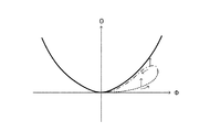
このように、ロール角Φの変化に対してピッチ角Θを制御して車両の操縦安定性を向上させるにあたっては、図4に示すように、二次関数によって表されるロール角Φとピッチ角Θとの間の相関関係を目標特性として採用し、旋回状態にある車体に発生した実ロール角Φに対して、実ピッチ角Θをこの目標特性における目標ピッチ角Θhに一致させる(近づける)ことができれば、良好な操縦安定性を確保することができる。ところが、車体に発生する実ロール角Φと実ピッチ角Θとは、例えば、乗員数や積載量の違いなどによって、同一の車両が同様に旋回する場合であっても異なる場合がある。 As described above, in order to improve the steering stability of the vehicle by controlling the pitch angle Θ with respect to the change of the roll angle Φ, as shown in FIG. 4, the roll angle Φ and the pitch angle represented by a quadratic function are used. Adopting the correlation with Θ as a target characteristic, for the actual roll angle Φ generated in the vehicle body in a turning state, make the actual pitch angle Θ coincide with (make closer to) the target pitch angle Θh in this target characteristic If it is possible, good steering stability can be ensured. However, the actual roll angle Φ and the actual pitch angle Θ generated in the vehicle body may differ even when the same vehicle turns in the same manner due to, for example, a difference in the number of passengers and the load capacity.
この場合、目標特性を変更不可に予め設定している場合には、目標特性と、実ロール角Φおよび実ピッチ角Θとによって表わされる車両の実特性とが離れてしまい、実ピッチ角Θを目標ピッチ角Θhまで変化させるときの制御追従性を確保できなくなる場合がある。このことを具体的に図5を用いて説明すると、今、実線で示す目標特性に対して、破線で示すように実ロール角Φが増大するときの実特性が下回っている状態を想定すると、操縦安定性を確保する観点から、実ピッチ角Θを大きくして目標特性における目標ピッチ角Θhに近づけることが必要となる。 In this case, when the target characteristic is set in advance so as not to be changed, the target characteristic is separated from the actual characteristic of the vehicle represented by the actual roll angle Φ and the actual pitch angle Θ. In some cases, it is not possible to ensure control followability when changing to the target pitch angle Θh. This will be specifically described with reference to FIG. 5. Assuming that the actual characteristic when the actual roll angle Φ increases as shown by the broken line is lower than the target characteristic indicated by the solid line, From the viewpoint of ensuring steering stability, it is necessary to increase the actual pitch angle Θ to approach the target pitch angle Θh in the target characteristics.
この場合の変化特性は、図5からも明らかなように、目標特性における目標ピッチ角Θhおよび実特性における実ピッチ角Θが実ロール角Φの増大に伴ってともに増大する傾向、言い換えれば、車体がより前傾姿勢となる傾向にあるため、目標ピッチ角Θhに近づけるように実ピッチ角Θを変化させることは可能となる。すなわち、この場合には、サスペンションECU13が、例えば、前輪側の左右ショックアブソーバ11a,11bの減衰力を低下させて制御することによって、実ピッチ角Θを目標ピッチ角Θhに近づけるように制御することは可能である。また、この場合、旋回状態における車体の姿勢変化としては自然であり、運転者は車体の姿勢変化に対して違和感を覚えない。
As is apparent from FIG. 5, the change characteristic in this case has a tendency that the target pitch angle Θh in the target characteristic and the actual pitch angle Θ in the actual characteristic increase as the actual roll angle Φ increases, in other words, the vehicle body Therefore, the actual pitch angle Θ can be changed to approach the target pitch angle Θh. That is, in this case, the
ところが、図5にて一点鎖線で示すように、実ロール角Φが減少するときの実特性が目標特性に対して下回っている状態を想定すると、この場合にも、操縦安定性を確保する観点から実ピッチ角Θを大きくして目標特性における目標ピッチ角Θhに近づけることが必要となる。しかし、この場合の変化傾向は、目標特性における目標ピッチ角Θhが実ロール角Φの減少に伴って一様に減少する傾向、言い換えれば、車体が前傾姿勢から水平姿勢に戻る傾向であるのに対して、実ピッチ角Θは実ロール角Φの減少に伴って目標ピッチ角Θhに向けて一旦増大した後一様に減少する傾向、言い換えれば、車体がより大きく前傾姿勢となってから水平姿勢に戻るようになる。この場合、旋回状態における車体の姿勢変化としては不自然であり、運転者は車体の姿勢変化に対して違和感を覚える。 However, as shown by the one-dot chain line in FIG. 5, assuming that the actual characteristic when the actual roll angle Φ decreases is lower than the target characteristic, in this case also, the viewpoint of ensuring the steering stability. Therefore, it is necessary to increase the actual pitch angle Θ to approach the target pitch angle Θh in the target characteristics. However, the change tendency in this case is that the target pitch angle Θh in the target characteristic tends to decrease uniformly as the actual roll angle Φ decreases, in other words, the vehicle body tends to return from the forward leaning posture to the horizontal posture. On the other hand, the actual pitch angle Θ tends to decrease uniformly after increasing once toward the target pitch angle Θh as the actual roll angle Φ decreases. It returns to the horizontal posture. In this case, the change in the posture of the vehicle body in the turning state is unnatural, and the driver feels uncomfortable with the change in the posture of the vehicle body.
また、実ロール角Φの変化に対して実特性における実ピッチ角Θが予め設定された目標特性における目標ピッチ角Θhに対して常に下回る状況では、実ロール角Φの増大または減少に伴って実ピッチ角Θを目標ピッチ角Θhに近づけるように変化させることはできるものの、実ロール角Φと実ピッチ角Θとの間の位相差が大きくなる場合がある。その結果、良好な操縦安定性が確保できない可能性がある。 In a situation where the actual pitch angle Θ in the actual characteristics is always lower than the target pitch angle Θh in the preset target characteristics with respect to the change in the actual roll angle Φ, the actual roll angle Φ is increased or decreased. Although the pitch angle Θ can be changed to approach the target pitch angle Θh, the phase difference between the actual roll angle Φ and the actual pitch angle Θ may increase. As a result, good steering stability may not be ensured.
このため、サスペンションECU13は、現在の旋回状態における実特性(実ロール角Φと実ピッチ角Θ)を考慮し、二次関数によって表わされる目標特性を変更するための目標特性可変係数a_newを計算する。すなわち、サスペンションECU13は、図6に示すように、実ロール角Φが増大する状況で実ピッチ角Θを大きくして目標ピッチ角Θhに近づけることができるとともに実ロール角Φが減少する状況で実ピッチ角Θを小さくして目標ピッチ角Θhに近づけることができるように、目標特性可変係数a_newを計算する。
Therefore, the
具体的には、サスペンションECU13は、ロールレートセンサ17によって検出された実ロール角速度φを入力するとともにピッチレートセンサ18によって検出された実ピッチ角速度θを入力する。続いて、サスペンションECU13は、入力した実ロール角速度φを時間積分して実ロール角Φを計算するとともに、入力した実ピッチ角速度θを時間積分して実ピッチ角Θを計算する。そして、サスペンションECU13は、後述するように、今回の旋回状態における実ピッチ角Θのうち、左右前輪が転舵することによって発生する旋回ピッチ角Θ_fyの最大値である最大旋回ピッチ角Θ_fy_maxと、実ロール角Φの最大値である最大実ロール角Φ_maxとを用いた下記式1に従って目標特性可変係数a_newを計算する。
a_new=Θ_fy_max/(Φ_max)2 …式1
そして、サスペンションECU13は、目標特性可変係数a_newを計算すると、ステップS11に戻る。なお、後述するように、サスペンションECU13は、目標特性可変係数a_newを計算した後にステップS11を実行するときには、ロール制御が実行中であると判定する。
Specifically, the
a_new = Θ_fy_max / (Φ_max) 2 Equation 1
Then, the
一方、サスペンションECU13は、ステップS11にて、現在、ロール制御を実行していれば、「Yes」と判定してステップS14に進む。
On the other hand, if the roll ECU is currently executing the roll control in step S11, the
ステップS14においては、サスペンションECU13は、横加速度センサ14aによって検出された横加速度Glの絶対値が基準横加速度Gls以上であるか否かを判定する。以下、この判定について説明する。上述したように、サスペンションECU13は、前記ステップS13にて、実特性に応じて実ピッチ角Θを目標ピッチ角Θhに近づけられるように目標特性を変更するための目標特性可変係数a_newを計算する。これにより、実ロール角Φの変化に対する実ピッチ角Θの変化傾向と目標ピッチ角Θの変化傾向とを一致(フィティング)させることができる。
In step S14, the
ところで、前記式1によれば、目標特性可変係数a_newは、実ロール角Φの最大値と実ピッチ角Θの最大値(より詳しくは最大旋回ピッチ角Θ_fy_max)とを用いて計算される。この場合、車体に発生した実ロール角Φおよび実ピッチ角Θが非常に小さい状態、言い換えれば、ロールレートセンサ17およびピッチレートセンサ18によって検出されるロール角速度φおよびピッチ角速度θが非常に小さい状態では、これらセンサ17,18からサスペンションECU13に出力される信号の信号強度(所謂、SN比)が小さくなる場合がある。すなわち、この場合には、サスペンションECU13に出力される信号はノイズの強度が大きいため、実ロール角Φおよび実ピッチ角Θを正確に計算することが困難となる。その結果、前記式1に従って正確な目標特性可変係数a_newを計算できず、実ロール角Φの変化に対する実ピッチ角Θの変化傾向と目標ピッチ角Θの変化傾向とのフィッティング精度が低下する可能性がある。
By the way, according to Equation 1, the target characteristic variable coefficient a_new is calculated using the maximum value of the actual roll angle Φ and the maximum value of the actual pitch angle Θ (more specifically, the maximum turning pitch angle Θ_fy_max). In this case, the actual roll angle Φ and the actual pitch angle Θ generated in the vehicle body are very small, in other words, the roll angular velocity φ and the pitch angular velocity θ detected by the
このことに関し、例えば、サスペンションECU13に出力される信号のSN比を十分確保できるか否かを判定できる判定ロール角(判定ロール角速度)の大きさを予め実験的に設定しておき、サスペンションECU13が実ロール角Φ(検出ロール角速度φ)の大きさが判定ロール角(判定ロール角速度)の大きさに比して大きいか否かを判定することも可能である。しかしながら、実ロール角Φ(検出ロール角速度φ)は、上述したように、同一の車両が同様に旋回する場合であっても異なる場合があるため、実ロール角Φ(検出ロール角速度φ)に基づいてSN比の大きさを判定することは正確性に欠く可能性がある。
In this regard, for example, the magnitude of a determination roll angle (determination roll angular velocity) that can determine whether or not a sufficient signal-to-noise ratio of the signal output to the
このため、サスペンションECU13は、車両の状態変化によらずに車体にロール挙動を発生させる要因となる物理量として横加速度Glの大きさ(絶対値)を用い、この横加速度Glの絶対値と、SN比が大きくなるように予め設定された基準横加速度Glsとを比較する。すなわち、サスペンションECU13は、横加速度センサ14aによって検出された横加速度Glを入力し、この横加速度Glの絶対値が基準横加速度Gls以上であれば、ロールレートセンサ17およびピッチレートセンサ18によって出力される信号のSN比が大きいため、「Yes」と判定してステップ15に進む。これにより、より正確な実ロール角Φの最大値と実ピッチ角Θの最大値(より詳しくは最大旋回ピッチ角Θ_fy_max)とを用いて、目標特性可変係数a_newを計算することができる。
For this reason, the
一方、検出横加速度Glの絶対値が基準横加速度Gls未満であれば、ロールレートセンサ17およびピッチレートセンサ18によって出力される信号のSN比が小さいため、サスペンションECU13は「No」と判定してステップ20に進む。この場合は、ノイズの強度が大きく、正確な実ロール角Φの最大値と実ピッチ角Θの最大値(より詳しくは最大旋回ピッチ角Θ_fy_max)を用いることができないため、サスペンションECU13は、後述するように、現在設定している目標特性可変係数aを変更せずに目標特性を変更しない。
On the other hand, if the absolute value of the detected lateral acceleration Gl is less than the reference lateral acceleration Gls, the signal-to-noise ratio of the signals output by the
ステップS15においては、運転者による操舵ハンドルの操舵操作によってバネ上である車体にロール挙動が発生しているか否かを判定する。すなわち、サスペンションECU13は、判定条件A)操舵操作に伴って発生する推定ロール角Φeと実ロール角Φとの差分値(絶対値)が基準ロール角差分値Φs未満のとき、または、判定条件B)車体の上下加速度Gvの入力信号の中周波成分(例えば、ロール共振周波数近傍)の絶対値が基準上下加速度Gvs未満のときに、操舵操作によって車体にロール挙動が発生していると判定する。
In step S15, it is determined whether or not a roll behavior has occurred in the vehicle body that is on the spring by the steering operation of the steering wheel by the driver. That is, the
具体的に説明すると、サスペンションECU13は、操舵操作によって発生する推定ロール角Φeを計算するにあたり、まず、操舵角センサ16によって検出された操舵ハンドルの操舵角δに基づいて操舵操作によって発生する横加速度Gleを下記式2に従って計算する。
Gle=(1/(1+A・V2))・(V2・(δ/(n・L))) …式2
ただし、前記式2中のAはスタビリティーファクタ、Vは車速センサ15によって検出された車速V、nはステアリングギア比、Lは車両のホイールベースを表す。
Specifically, in calculating the estimated roll angle Φe generated by the steering operation, the
Gle = (1 / (1 + A ・ V 2 )) ・ (V 2・ (δ / (n ・ L))) ... Formula 2
In Equation 2, A is a stability factor, V is a vehicle speed V detected by the
次に、サスペンションECU13は、前記式2に従って計算した横加速度Gleを用い、車体に発生するロール挙動(ローリング運動)を表す下記式3の運動方程式に基づいて導出される下記式4に示す推定ロール角Φeの伝達関数を計算する。
I・d2Φ/dt2+C・dΦ/dt+R・Φ=M・h・Gle+M・g・h・Φ …式3
Φ(s)/Gle(s)=(M・h)/(I・s2+C・s+R−M・g・h) …式4
ただし、前記式3,4中のΦは車体のロール角、Iはバネ上(車体)の慣性モーメント、Cは減衰係数、Rはロール剛性、Mはバネ上(車体)の質量、hはロールセンタとバネ上(車体)の重心との間の距離、gは重力加速度を表す。また、前記式4中のsはラプラス演算子を表す。
Next, the
I · d 2 Φ / dt 2 + C · dΦ / dt + R · Φ = M · h · Gle + M · g · h · Φ Equation 3
Φ (s) / Gle (s) = (M · h) / (I · s 2 + C · s + R−M · g · h) Equation 4
Where Φ in Equations 3 and 4 is the roll angle of the vehicle body, I is the moment of inertia of the spring (vehicle body), C is the damping coefficient, R is roll stiffness, M is the mass of the spring (vehicle body), and h is the roll The distance between the center and the center of gravity of the sprung (vehicle body), g, represents the acceleration of gravity. Further, s in Equation 4 represents a Laplace operator.
そして、サスペンションECU13は、前記式4の伝達関数に基づいて推定ロール角Φeを計算するとともにロールレートセンサ17によって検出されたロール角速度φを時間積分して計算した実ロール角Φを計算する。これにより、サスペンションECU13は、推定ロール角Φeと実ロール角Φとの差分値(絶対値)が基準ロール角差分値Φs未満であるか否かを判定する。
Then, the
また、サスペンションECU13は、上下加速度センサ14cによって検出されて出力される上下加速度Gvを入力する。そして、入力した上下加速度Gvの入力信号の中周波成分の絶対値が基準上下加速度Gvs未満であるか否かを判定する。
Also, the
すなわち、サスペンションECU13は、ステップS15にて、判定条件A)が成立し、かつ、判定条件B)が成立する状況では、車体のロール挙動(ローリング運動)が操舵ハンドルの操舵操作によって発生しているため、「Yes」と判定してステップS16に進む。一方、サスペンションECU13は、判定条件A)および判定条件B)の一方のみが成立する状況または判定条件A)および判定条件B)の両方が成立しない状況では、車体のロール挙動(ローリング運動)が操舵ハンドルの操舵操作による以外に路面からの入力によっても発生しているため、「No」と判定してステップS20に進む。すなわち、この場合には、サスペンションECU13は、後述するように、現在設定している目標特性可変係数aを変更せずに目標特性を変更しない。
That is, in step S15, the
ステップS16においては、サスペンションECU13は、旋回状態において車両を制動または駆動(以下、制駆動という)したときに発生する車体のピッチ角すなわち制駆動ピッチ角Θ_fxを決定する。具体的に説明すると、旋回状態において運転者が車両を制駆動させるためにブレーキ操作やアクセル操作した場合には、前後加速度Gcが発生し、この前後加速度Gcの影響によって一般的に実ピッチ角Θは大きなったり小さくなったりする。すなわち、この場合には、左右前輪が転舵することによって発生する旋回ピッチ角Θ_fyに車両を制駆動することによって発生する制駆動ピッチ角Θ_fxが加算されて実ピッチ角Θが変化する。
In step S16, the
このため、サスペンションECU13は、前後加速度Gcに対する制駆動ピッチ角Θ_fxの関係を予め実験的に決定した図7に示すマップを参照して制駆動ピッチ角Θ_fxを決定する。すなわち、サスペンションECU13は、前後加速度センサ14bによって検出された前後加速度Gcを入力し、この入力した前後加速度Gcに対応する制駆動ピッチ角Θ_fxを決定してステップS17に進む。
Therefore, the
ステップS17においては、サスペンションECU13は、現在、車体に発生している実ピッチ角Θのうち、旋回ピッチ角Θ_fyを計算する。上述したように、旋回状態において車両を制駆動すると、制駆動ピッチ角Θ_fxが加算されて実ピッチ角Θが変化する。ここで、制駆動ピッチ角Θ_fxは、車両を制駆動したときのみ発生するものである。このため、例えば、前記式1において制駆動ピッチ角Θ_fxが加算された実ピッチ角Θを用いて目標特性可変係数a_newを計算した場合には、制駆動の有無により、目標特性可変係数a_newの値が変化することになる。すなわち、制駆動ピッチ角Θ_fxを加味して目標特性可変係数a_newを計算した場合には、実ロール角Φの変化に対する実ピッチ角Θの変化傾向と目標ピッチ角Θの変化傾向とを一致(フィティング)させる精度が悪化する。このことに基づき、上述したように、前記式1においては、左右前輪が転舵することによって発生する旋回ピッチ角Θ_fy(より詳しくは最大旋回ピッチ角Θ_fy_max)のみを用いて目標特性可変係数a_newを計算するようになっている。
In step S17, the
したがって、サスペンションECU13は、前記式1に従ってより正確な目標特性可変係数a_newを計算するために、このステップS17にて、実ピッチ角Θから制駆動ピッチ角Θ_fxを除くことによって旋回ピッチ角Θ_fyを計算する。すなわち、サスペンションECU13は、下記式5に従って旋回ピッチ角Θ_fyを計算する。
Θ_fy=Θ−Θ_fx …式5
そして、サスペンションECU13は、旋回ピッチ角Θ_fyを計算すると、ステップS18に進む。
Accordingly, the
Θ_fy = Θ−Θ_fx Equation 5
When the
ステップS18においては、サスペンションECU13は、現在の旋回状態における実ロール角Φの最大値である最大実ロール角Φ_maxと前記ステップS17にて計算した旋回ピッチ角Θ_fyの最大値である最大旋回ピッチ角Θ_fy_maxとを保持(ラッチ)する。すなわち、サスペンションECU13は、旋回状態において時々刻々と変化する実ロール角Φと旋回ピッチ角Θ_fyとを順次、例えば、RAM内の所定記憶位置に記憶し、この順次記憶した実ロール角Φと旋回ピッチ角Θ_fyのうち、最大実ロール角Φ_maxと最大旋回ピッチ角Θ_fy_maxとをラッチして最終的に記憶する。そして、サスペンションECU13は、図6に示したように、このラッチした最大実ロール角Φ_maxと最大旋回ピッチ角Θ_fy_maxとによって定まる点を目標特性が通過するように、すなわち、前記式1に従うことにより、次回以降に実行する前記ステップS13にて目標特性可変係数a_newを計算する。このように、最大実ロール角Φ_maxと最大旋回ピッチ角Θ_fy_maxとをラッチして最終的に記憶すると、サスペンションECU13はステップS19に進む。
In step S18, the
ステップS19においては、サスペンションECU13は、変更許可フラグFRG_Aの設定値を、変更を許可しない「0」から変更を許可する「1」に設定する。すなわち、このステップS19を実行する状況は、現在、車両が旋回状態にあってロール制御を実行しており(ステップS11にて「Yes」判定)、ステップS14およびステップS15における判定条件が成立して「Yes」と判定している状況である。さらに、これらステップS14およびステップS15における「Yes」判定に基づき、ステップS16〜ステップS18を実行して最大実ロール角Φ_maxと最大旋回ピッチ角Θ_fy_maxとをラッチして最終的に記憶している状況である。
In step S19, the
言い換えれば、前回までのロール制御プログラムの実行により計算した目標特性可変係数aを用いて変更した目標特性に基づいてショックアブソーバ11a,11b,11c,11dの減衰力を適切に制御している状態から、新たに前記ステップS13にて計算した目標特性可変係数a_newを用いて変更した新たな目標特性に基づいてショックアブソーバ11a,11b,11c,11dの減衰力を制御する状態に移行できる状況となっている。したがって、サスペンションECU13は、目標特性を変更するために変更許可フラグFRG_Aの設定値を「0」に代えて「1」に設定し、ステップS20に進む。
In other words, from the state in which the damping force of the
ステップS20においては、サスペンションECU13は、前記ステップS14またはステップS15の判定処理において判定条件が成立しておらず「No」と判定した場合には、前回までのロール制御プログラムの実行により、前記ステップS13にて計算した目標特性可変係数a_newに設定した目標特性可変係数aを変更することなく維持する。一方、前記ステップS19にて変更許可フラグFRG_Aの設定値が「0」から「1」に変更された場合には、サスペンションECU13は、次回以降のステップS20の実行において目標特性可変係数aを新たに計算した目標特性可変係数a_newに変更する。なお、イグニッションスイッチがオン状態とされた後、前記ステップS14またはステップS15の判定処理において「No」と判定して最初にステップS20の処理が実行するときには、サスペンションECU13は、目標特性可変係数aを、例えば、ROM内に予め記憶されている初期値に設定するようになっている。
In step S20, when the determination condition in step S14 or step S15 is not satisfied and the determination is “No”, the
ここで、目標特性可変係数aを目標特性可変係数a_newに変更する場合、サスペンションECU13は、車両の姿勢状態量(実ロール角Φと実ピッチ角Θ)の変化に対応して、目標特性可変係数aの更新頻度(学習特性)を適宜変更する。具体的に説明すると、サスペンションECU13は、車両の姿勢状態量の大幅な変化が予測されるとき、詳しくは、条件a)イグニッションスイッチがオン状態とされてから所定時間が経過するまで、条件b)トランクリッドの開閉操作後に目標特性可変係数aが最初に更新されるまで、条件c)乗降ドアの開閉操作後に目標特性可変係数aが最初に更新されるまでのときは、目標特性可変係数a_newの計算頻度を高くして目標特性可変係数aの更新頻度を高く(言い換えれば、学習する速度を大きく)する。
Here, when the target characteristic variable coefficient a is changed to the target characteristic variable coefficient a_new, the
具体的には、条件a)〜c)のうちの少なくとも一つが成立する場合には、車両の姿勢状態量が変化する可能性が極めて高くなる。このため、サスペンションECU13は、目標特性可変係数aの変更許容幅(レートリミッタ)を大きく設定して目標特性可変係数aの更新頻度を高めたり、目標特性可変係数aの更新に関与するローパスフィルタ(LPF)の時定数を小さく設定する。これにより、目標特性可変係数aの更新頻度を高くして(学習速度を大きくして)、目標特性可変係数aを目標特性可変係数a_newに変更することができる。
Specifically, when at least one of the conditions a) to c) is satisfied, the possibility that the posture state quantity of the vehicle changes is extremely high. For this reason, the
一方、サスペンションECU13は、車両の姿勢状態量の変化が予測されないとき、詳しくは、条件d)イグニッションスイッチがオン状態とされてから所定時間が経過している、条件e)トランクリッドの開閉操作後に目標特性可変係数aが更新された、条件f)乗降ドアの開閉操作後に目標特性可変係数aが更新されたときは、目標特性可変係数a_newの計算頻度を低くして目標特性可変係数aを学習する速度を小さくする。すなわち、条件d)〜f)が全て成立する場合には、車両の姿勢状態量の変化が小さく、すでに目標特性可変係数aの更新(学習)がある程度できている。このため、サスペンションECU13は、目標特性可変係数aの変更許容幅(レートリミッタ)を小さく設定して目標特性可変係数aの更新頻度を低くしたり、目標特性可変係数aの更新に関与するローパスフィルタ(LPF)の時定数を大きく設定する。これにより、目標特性可変係数aの更新頻度を低くして(学習速度を低くして)、目標特性可変係数aを目標特性可変係数a_newに変更することができる。
On the other hand, when the change of the vehicle posture state quantity is not predicted, the
このように、車両の姿勢状態量変化に対応して、目標特性可変係数aの更新頻度(学習特性)を適宜変更することにより、目標特性可変係数aの更新に関するロバスト性を良好に確保することができる。そして、サスペンションECU13は、ステップS20にて、目標特性可変係数aを目標特性可変係数a_newに変更すると、変更許可フラグFRG_Aの設定値を「1」から「0」に戻してステップS21に進む。
As described above, by appropriately changing the update frequency (learning characteristic) of the target characteristic variable coefficient a corresponding to the change in the posture state quantity of the vehicle, the robustness related to the update of the target characteristic variable coefficient a is ensured satisfactorily. Can do. When the
ステップS21においては、サスペンションECU13は、前記ステップS20にて設定した目標特性可変係数aによって適宜変更した目標特性に基づいてショックアブソーバ11a,11b,11c,11dの減衰力を制御する減衰力制御ルーチンを実行する。以下、この減衰力制御ルーチンを説明する。
In step S21, the
サスペンションECU13は、図8に示す減衰力制御ルーチンの実行をステップS100にて開始する。そして、サスペンションECU13は、続くステップS101において、前記ステップS20にて設定した目標特性可変係数a(目標特性可変係数a_new)を用いた下記式6によって表わされる目標特性に基づいて、目標ピッチ角Θhを計算する。
Θh=a・Φ2 …式6
ただし、前記式6中のΦは、ロールレートセンサ17によって検出されたロール角速度φを時間積分して計算した実ロール角を表す。そして、サスペンションECU13は、目標ピッチ角Θhを計算すると、ステップS102に進む。
The
Θh = a · Φ 2 ... Formula 6
However, Φ in Equation 6 represents an actual roll angle calculated by time integration of the roll angular velocity φ detected by the
ステップS102においては、サスペンションECU13は、前記ステップS101にて計算した目標ピッチ角Θhと実ピッチ角Θとの差分値ΔΘを下記式7に従って計算する。
ΔΘ=Θh−Θ …式7
ただし、前記式7中のΘは、ピッチレートセンサ18によって検出されたピッチ角速度θを時間積分して計算した実ピッチ角を表す。そして、サスペンションECU13は、差分値ΔΘを計算すると、ステップS103に進む。
In step S102, the
ΔΘ = Θh−Θ Equation 7
However, Θ in Expression 7 represents an actual pitch angle calculated by time integration of the pitch angular velocity θ detected by the
ステップS103においては、サスペンションECU13は、前記ステップS103にて計算した差分値ΔΘを「0」とするために必要となる前輪側の左右ショックアブソーバ11a,11bおよび後輪側の左右ショックアブソーバ11c,11dに対する総減衰力としての総要求減衰力Fを計算する。以下、この総要求減衰力Fの計算について説明するが、この計算に関しては、周知の種々の方法を採用することができるため、その詳細な説明を省略し、例示的に簡単に説明する。
In step S103, the
車体に発生する実ピッチ角Θを目標ピッチ角Θhまで変化させるために必要な総要求減衰力Fは、ピッチモーメントPmを用いて計算することができる。すなわち、ピッチモーメントPmは、下記式8により計算することができる。
Pm=I・(ΔΘ)''+C・(ΔΘ)'+K・(ΔΘ) …式8
ただし、前記式8中のIは慣性モーメント、Cは減衰係数、Kはバネ定数を表す。また、前記式8中のΔΘは前記ステップS102にて計算した差分値、(ΔΘ)''は差分値ΔΘの2階微分値、(ΔΘ)'は差分値ΔΘの微分値を表す。
The total required damping force F required to change the actual pitch angle Θ generated in the vehicle body to the target pitch angle Θh can be calculated using the pitch moment Pm. That is, the pitch moment Pm can be calculated by the following formula 8.
Pm = I · (ΔΘ) ″ + C · (ΔΘ) ′ + K · (ΔΘ) Equation 8
In Equation 8, I represents the moment of inertia, C represents the damping coefficient, and K represents the spring constant. In the equation 8, ΔΘ represents the difference value calculated in step S102, (ΔΘ) ″ represents the second-order differential value of the difference value ΔΘ, and (ΔΘ) ′ represents the differential value of the difference value ΔΘ.
そして、総要求減衰力Fは、前記式8によって表わされる車体前後方向のピッチモーメントPmを車両のホイールベースLで除算することによって計算することができる。すなわち、総要求減衰力Fは、下記式9に従って計算することができる。
F=Pm/L …式9
このように、総要求減衰力Fを計算すると、サスペンションECU13は、ステップS104に進む。
The total required damping force F can be calculated by dividing the vehicle body longitudinal pitch moment Pm represented by the equation 8 by the vehicle wheel base L. That is, the total required damping force F can be calculated according to the following formula 9.
F = Pm / L ... Formula 9
When the total required damping force F is thus calculated, the
ステップS104においては、サスペンションECU13は、前記ステップS103にて計算した総要求減衰力Fを前輪側の左右ショックアブソーバ11a,11b間および後輪側の左右ショックアブソーバ11c,11d間で分配するための分配計算を実行する。なお、以下の説明においては、前輪側と後輪側とで同様に計算することができるため、前輪側の左右ショックアブソーバ11a,11bを代表して説明するものとし、また、車両が左旋回している場合を挙げて説明する。
In step S104, the
総要求減衰力Fを左右のショックアブソーバ11a,11bに分配するにあたり、サスペンションECU13は、旋回状態にある車体に発生した横加速度Glの大きさに比例する分配量Xを用いる。具体的に説明すると、今、車両の前輪側に対して総要求減衰力Fが要求される状況を想定すると、まず、各ショックアブソーバ11a,11bには、総要求減衰力Fが均等に分配される。
In distributing the total required damping force F to the left and
そして、サスペンションECU13は、各ショックアブソーバ11a,11bに均等に分配した要求減衰力(F/2)に対して、分配量Xを加算する。このとき、サスペンションECU13は、横加速度センサ14aから入力した検出横加速度Glの発生方向(この場合は左方向)に基づき、旋回内側に対応するショックアブソーバ11aの要求減衰力(F/2)に対して、正の分配量Xを加算する。一方、サスペンションECU13は、旋回外側に対応するショックアブソーバ11bの要求減衰力(F/2)に対して、負の分配量Xを加算する。
Then, the
すなわち、旋回内側に対応するショックアブソーバ11aに要求される減衰力Fiと旋回外側に対応するショックアブソーバ11bに要求される減衰力Foは、下記式10,11で表わされる。
Fi=(F/2)+X …式10
Fo=(F/2)−X …式11
ここで、上述したように、分配量Xは、横加速度Glの大きさに比例するため、下記式12により表すことができる。
X=α・(F/2) …式12
ただし、前記式12におけるαは、横加速度Glの大きさに比例して変化する変数であり、下記式13により表される。
α= (1+|Gl|・J) …式13
なお、前記式13中のJは、サスペンションECU13によるロール制御に関し、例えば、運転者によって選択される乗り心地優先制御やスポーツ走行優先制御などにより変化し得る正の変数である。
That is, the damping force Fi required for the
Fi = (F / 2) + X (Formula 10)
Fo = (F / 2) −X Equation 11
Here, as described above, the distribution amount X is proportional to the magnitude of the lateral acceleration Gl, and therefore can be expressed by the following
X = α · (F / 2) ...
However, α in the
α = (1+ | Gl | · J)
Note that J in the
ところで、前記式10〜13の関係に基づけば、旋回内側のショックアブソーバ11aに要求される減衰力Fiは常に正の値となり、旋回外側のショックアブソーバ11bに要求される減衰力Foは常に負の値となる関係が成立する。また、旋回内側のショックアブソーバ11aに対する要求減衰力Fiと旋回外側のショックアブソーバ11bに対する要求減衰力Foとを互いに加算すると、前輪側に要求される総要求減衰力Fとなる。このように、旋回内側と旋回外側とに対して総要求減衰力Fを分配することにより、車体に適切な実ロール角Φを生じさせることができるとともに実ピッチ角Θを目標ピッチ角Θhまで確実に変化させることができる。
By the way, based on the relations of the
そして、車両の旋回内側に対応するショックアブソーバ11a(ショックアブソーバ11c)に要求減衰力Fiを分配し、旋回外側に対応するショックアブソーバ11b(ショックアブソーバ11d)に要求減衰力Foを分配すると、サスペンションECU13は、ステップS105に進む。
When the required damping force Fi is distributed to the
ステップS105においては、サスペンションECU13は、旋回内側に対応するショックアブソーバ11a,11cが前記ステップS104にて決定した要求減衰力Fiを発生するように、また、旋回外側に対応するショックアブソーバ11b,11dが前記ステップS104にて決定した要求減衰力Foを発生するように、駆動回路19a,19b,19c,19dを駆動制御する。これにより、ショックアブソーバ11a,11b,11c,11dのロータリーバルブ12a,12b,12c,12dがそれぞれ作動流体の流路径を変更する。したがって、ショックアブソーバ11a,11b,11c,11dが発生する減衰力が、車両の旋回方向に応じて、それぞれ要求減衰力Fiまたは要求減衰力Foと一致するようになる。
In step S105, the
このように、サスペンションECU13は、ショックアブソーバ11a,11b,11c,11dの減衰力を適宜変更すると、ステップS106に進み、減衰力制御ルーチンの実行を終了し、ロール制御プログラムに戻る。そして、サスペンションECU13は、ロール制御プログラムのステップS11以降をふたたび実行する。
As described above, when the
ここで、サスペンションECU13は、上述した減衰力制御ルーチンの実行後にステップS11の判定処理を実行するにあたり、以下のように判定する。まず、サスペンションECU13は、前記ステップS14またはステップS15の判定処理において「No」と判定した場合、言い換えれば、前記ステップS19にて変更許可フラグFRG_Aの設定値を変更していない場合には、現在設定している目標特性可変係数aを変更する必要がないため、ロール制御が実行中であると判定する。すなわち、この場合には、サスペンションECU13は、ステップS11にて「Yes」と判定してステップS14以降の各ステップ処理を実行する。
Here, the
一方、サスペンションECU13は、前記ステップS14およびステップS15の判定処理において「Yes」と判定した場合、言い換えれば、前記ステップS19にて変更許可フラグFRG_Aの設定値を「1」に変更した場合には、目標特性可変係数a_newを新たに計算して現在設定している目標特性可変係数aを変更する必要がある。このため、サスペンションECU13は、減衰力制御ルーチンの実行によって設定したショックアブソーバ11a,11b,11c,11dの減衰力を維持した状態で、ロール制御の実行を一旦中断する。これにより、サスペンションECU13は、ステップS11にて「No」と判定してステップS12に進み、前記ステップS19の変更処理に基づく「Yes」判定によってステップS13にて目標特性可変係数a_newを計算する。そして、サスペンションECU13は、次回実行するステップS11にてロール制御の実行を再開することにより「Yes」と判定し、ステップS14以降の各ステップ処理を実行する。
On the other hand, when the
以上の説明からも理解できるように、この第1実施形態によれば、サスペンションECU13は、前記ステップS19にて変更許可フラグFRG_Aの設定値を「0」から「1」に変更することによって前記ステップS13にて前記式1に従って目標特性可変係数a_newを計算し、ステップS20にて目標特性可変係数aを目標特性可変係数a_newに設定することによって目標特性を変更することができる。これにより、実ロール角Φが増大する状況においては、実ピッチ角Θに比して目標ピッチ角Θhを大きくなるように目標特性を設定することができる。したがって、実ロール角Φの増大に伴って増加する目標ピッチ角Θhの変化傾向に合わせて実ピッチ角Θが変化するように、言い換えれば、実ロール角Φの増大に伴って実ピッチ角Θが目標ピッチ角Θhに向けて大きくなるように、旋回内側のショックアブソーバの減衰力Fiと旋回外側のショックアブソーバの減衰力Foを相対的に低下させて変更することができる。
As can be understood from the above description, according to the first embodiment, the
一方、実ロール角Φが減少する状況においては、実ピッチ角Θに比して目標ピッチ角Θhを小さくなるように目標特性を設定することができる。したがって、実ロール角Φの減少に伴って減少する目標ピッチ角Θhの変化傾向に合わせて実ピッチ角Θが変化するように、言い換えれば、実ロール角Φの減少に伴って実ピッチ角Θが目標ピッチ角Θhに向けて小さくなるように、旋回内側のショックアブソーバの減衰力Fiと旋回外側のショックアブソーバの減衰力Foを相対的に増加させて変更することができる。 On the other hand, in a situation where the actual roll angle Φ decreases, the target characteristic can be set so that the target pitch angle Θh is smaller than the actual pitch angle Θ. Therefore, the actual pitch angle Θ is changed in accordance with the change tendency of the target pitch angle Θh that decreases as the actual roll angle Φ decreases. The damping force Fi of the shock absorber on the inside of the turn and the damping force Fo of the shock absorber on the outside of the turn can be relatively increased and changed so as to decrease toward the target pitch angle Θh.
これにより、現実的な変更制御によってショックアブソーバ11a,11b,11c,11dの減衰力Fi,Foを制御することができ、実ピッチ角Θを目標ピッチ角Θhに向けて確実に変化させることができる。また、実ロール角Φの変化に対する目標ピッチ角Θhの変化傾向に合わせて実ピッチ角Θを変化させることができるため、ロールとピッチの発生タイミングにおける位相差を小さくすることができ、車両旋回時における良好な操縦安定性を良好に確保することができる。
Thereby, the damping forces Fi and Fo of the
また、サスペンションECU13は、前記式1に従って目標特性可変係数a_newを計算するにあたり、最大旋回ピッチ角Θ_fy_maxを用いることができる。これにより、現在の車両の旋回状態における実特性を極めて正確に反映して目標特性可変係数a_newを計算することができ、例えば、旋回状態における制駆動に伴って発生する制駆動ピッチ角Θ_fxが姿勢変化に与える影響を確実に防止することができる。また、旋回状態における実特性を極めて正確に反映した目標特性可変係数a_newを計算できるため、この目標特性可変係数a_newを順次学習(更新)することによってより適切な目標特性を設定することができる。
In addition, the
また、前記ステップS14の判定処理を実行することによって、より適切に目標特性可変係数a_newを計算するか否かを判別することができる。すなわち、検出横加速度Glが基準横加速度Gls以上であるときに前記ステップS19にて変更許可フラグFRG_Aの設定値を「0」から「1」に変更し、ステップS13にて目標特性可変係数a_newを計算することができる。これにより、不正確な目標特性可変係数a_newを計算することを防止することもできる。 Further, it is possible to determine whether or not to calculate the target characteristic variable coefficient a_new more appropriately by executing the determination process of step S14. That is, when the detected lateral acceleration Gl is equal to or greater than the reference lateral acceleration Gls, the set value of the change permission flag FRG_A is changed from “0” to “1” in step S19, and the target characteristic variable coefficient a_new is set in step S13. Can be calculated. As a result, it is possible to prevent the calculation of an inaccurate target characteristic variable coefficient a_new.
また、前記ステップS15にて、上述した判定条件A)および判定条件B)の一方または両方が成立しない場合には、例えば、路面からの上下方向の入力に伴って発生する無駄なロール挙動が発生している可能性が高い。このため、サスペンションECU13は、前記ステップS19を実行することなく、ステップS13にて目標特性可変係数a_newを計算しない。これにより、無駄なロール挙動の影響を適切に排除し、車両の旋回に伴ってロール挙動が発生したときの目標特性可変係数a_newを計算することができる。したがって、目標特性可変係数を順次学習(更新)することによってより適切な目標特性を設定することができる。
In step S15, when one or both of the above-described determination condition A) and determination condition B) are not satisfied, for example, useless roll behavior that occurs due to the vertical input from the road surface occurs. It is highly possible that For this reason, the
また、前記ステップS20にて、上述した条件a)〜条件c)が成立するとき、すなわち、実ロール角Φおよび実ピッチ角Θによって表わされる実特性が変化しやすい状況では、目標特性可変係数a_newの更新(変更)頻度、言い換えれば、目標特性の更新(変更)頻度を高めることができる。これにより、実特性が変化した場合であっても、この変化した実特性(実ロール角Φと実ピッチ角Θ)に応じた目標特性を繰り返し更新(変更)することができるため、変化した実特性を良好に反映した目標特性に変更することができる。そして、この目標特性の更新(変更)頻度を高めて計算した目標特性可変係数a_new順次学習(更新)することによってロバスト性を向上させることができて、より適切な目標特性を設定することができる。 Further, when the above-described conditions a) to c) are satisfied in step S20, that is, in a situation where the actual characteristics represented by the actual roll angle Φ and the actual pitch angle Θ are likely to change, the target characteristic variable coefficient a_new. Update (change) frequency, in other words, the update (change) frequency of the target characteristic can be increased. As a result, even if the actual characteristics change, the target characteristics corresponding to the changed actual characteristics (actual roll angle Φ and actual pitch angle Θ) can be repeatedly updated (changed). The target characteristic can be changed to reflect the characteristic well. Then, the target characteristic variable coefficient a_new calculated by increasing the frequency of updating (changing) the target characteristic can be sequentially learned (updated) to improve the robustness, and a more appropriate target characteristic can be set. .
本発明の実施にあたっては、上記各実施形態に限定されるものではなく、本発明の目的を逸脱しない限りにおいて、種々の変更が可能である。 In carrying out the present invention, the present invention is not limited to the above embodiments, and various modifications can be made without departing from the object of the present invention.
例えば、上記実施形態においては、ロール制御プログラムにおいて、サスペンションECU13が、ステップS14にて判定条件の成立により「Yes」と判定し、かつ、ステップS15にて判定条件A)および判定条件A)の判定条件の成立により「Yes」と判定するときに、ステップS16〜ステップS19を実行するように実施した。しかしながら、ステップS14およびステップS15のうちの一方のみを判定処理し、この判定処理により判定条件が成立するときにステップS16〜ステップS19を実行するように実施することも可能である。この場合であっても、上記実施形態と同様の効果が期待できる。
For example, in the above-described embodiment, in the roll control program, the
また、この場合、サスペンションECU13がステップS14の判定処理のみを実行する場合において、例えば、上述した条件a)イグニッションスイッチがオン状態とされてから所定時間が経過するまで、条件b)トランクリッドの開閉操作後に目標特性可変係数aが最初に更新されるまで、および、条件c)乗降ドアの開閉操作後に目標特性可変係数aが最初に更新されるまでのうちの少なくとも一つの条件が成立する場合には、基準横加速度Glsを小さく設定して実施することも可能である。これにより、サスペンションECU13は、ステップS14にて「Yes」と判定する頻度が増加してステップS19における変更許可フラグFRG_Aの変更頻度が増加し、その結果、ステップS13における目標特性可変係数a_newの計算頻度を増加させることができる。したがって、この場合には、ステップS20における目標特性可変係数aの変更頻度、言い換えれば、目標特性の変更頻度を増加させることができるという効果も期待できる。
Further, in this case, when the
また、サスペンションECU13がステップS15の判定処理のみを実行する場合においても、例えば、上述した条件a)〜条件c)のうちの少なくとも一つが成立する場合には、基準ロール角Φsおよび基準上下加速度Gvsをともに大きく設定して実施することも可能である。これにより、サスペンションECU13は、ステップS15にて「Yes」と判定する頻度が増加してステップS19における変更許可フラグFRG_Aの変更頻度が増加し、その結果、ステップS13における目標特性可変係数a_newの計算頻度を増加させることができる。したがって、この場合にも、ステップS20における目標特性可変係数aの変更頻度、言い換えれば、目標特性の変更頻度が増加させることができるという効果も期待できる。
Even when the
また、上記実施形態においては、減衰力制御ルーチンを実行して、サスペンションECU13が物理量検出手段としての横加速度センサ14aによって検出された横加速度Glに応じて、各ショックアブソーバ11a,11b,11c,11dの要求減衰力Fi,Foを決定して減衰力を制御するように実施した。これに対して、例えば、車両に発生するヨーレートの大きさに基づいて、前記ステップS14の判定処理および減衰力制御ルーチンを実行することも可能である。この場合には、発生したヨーレートを検出し、同検出したヨーレートをサスペンションECU13に出力するヨーレートセンサを設けるとよい。
In the above embodiment, the damping force control routine is executed, and the
このように、車両に発生するヨーレートを用いる場合であっても、ロール制御プログラムにおいて、サスペンションECU13がステップS14にてヨーレートセンサによって出力される信号のSN比が大きいか否かを判定することができて、より正確な目標特性可変係数a_newを計算する、言い換えれば、フィッティング精度を良好に確保することができる。また、減衰力制御ルーチンにおいて、サスペンションECU13がヨーレートの絶対値の大きさに比例する変数αを用いて分配量Xを計算することができる。そして、サスペンションECU13が旋回内側に対応するショックアブソーバの要求減衰力Fiおよび旋回外側に対応するショックアブソーバの要求減衰力Foを計算することにより、上記実施形態と同様の効果を得ることができる。
Thus, even when the yaw rate generated in the vehicle is used, in the roll control program, the
また、例えば、操舵角センサ16によって検出される操舵角δの大きさに基づいて、前記ステップS14の判定処理および減衰力制御ルーチンを実行することも可能である。このように、操舵ハンドルの操作に起因する操舵角δを用いる場合であっても、ロール制御プログラムにおいて、サスペンションECU13がステップS14にて操舵角センサ16によって出力される信号のSN比が大きいか否かを判定することができて、より正確な目標特性可変係数a_newを計算する、言い換えれば、フィッティング精度を良好に確保することができる。また、減衰力制御ルーチンにおいて、サスペンションECU13が操舵角δの絶対値の大きさに比例する変数αを用いて分配量Xを計算することができる。そして、サスペンションECU13が旋回内側に対応するショックアブソーバの要求減衰力Fiおよび旋回外側に対応するショックアブソーバの要求減衰力Foを計算することにより、上記実施形態と同様の効果を得ることができる。
Further, for example, based on the magnitude of the steering angle δ detected by the
さらに、上記実施形態においては、ロールレートセンサ17がロール角速度φを検出し、ピッチレートセンサ18がピッチ角速度θを検出し、サスペンションECU13がこれら検出されたロール角速度φおよびピッチ角速度θを時間積分して実ロール角Φと実ピッチ角Θとを計算するように実施した。この場合、車体に発生したロール角とピッチ角とを直接検出するセンサを設けて実施可能であることはいうまでもない。
Furthermore, in the above embodiment, the
10…減衰力制御装置、11a,11b,11c,11d…ショックアブソーバ、12a,12b,12c,12d…ロータリーバルブ、13…サスペンションECU、14a…横加速度センサ、14b…前後加速度センサ、14c…上下加速度センサ、15…車速センサ、16…操舵角センサ、17…ロールレートセンサ、18…ピッチレートセンサ、19a,19b,19c,19d…駆動回路
DESCRIPTION OF
Claims (12)
車両の旋回に伴って変化する所定の物理量を検出する物理量検出手段と、
前記車体の左右方向に発生した実ロール角と前記車体の前後方向に発生した実ピッチ角とを検出する姿勢状態量検出手段と、
前記車体に発生したロール挙動を制御するためのロール角とピッチ角との間の関係を表す目標特性であってロール角の変化に対してピッチ角が二次関数に従って変化する目標特性を前記姿勢状態量検出手段によって検出された前記実ロール角および前記実ピッチ角によって表わされる車両の実特性に応じて変更する目標特性可変係数を計算する目標特性可変係数計算手段と、
前記目標特性可変係数計算手段によって計算された前記目標特性可変係数を用いて、前記目標特性を変更する目標特性変更手段と、
前記目標特性変更手段によって変更された前記目標特性に基づいて、車両の前輪側に配設される左右のショックアブソーバおよび車両の後輪側に配設される左右のショックアブソーバが協働して発生すべき総減衰力を計算する総減衰力計算手段と、
前記総減衰力計算手段によって計算された総減衰力を前記物理量検出手段によって検出された所定の物理量に応じて旋回内側に配設されるショックアブソーバと旋回外側に配設されるショックアブソーバとに分配する総減衰力分配手段と、
前記総減衰力分配手段によって分配された前記旋回内側に配設されるショックアブソーバの減衰力および前記旋回外側に配設されるショックアブソーバの減衰力に基づいて、各ショックアブソーバの減衰力を変更制御する減衰力制御手段とを備えたことを特徴とする車両の減衰力制御装置。 In the vehicle damping force control device for changing and controlling the damping force of the shock absorber disposed between the vehicle body and the wheel,
Physical quantity detection means for detecting a predetermined physical quantity that changes as the vehicle turns,
Posture state quantity detection means for detecting an actual roll angle generated in the lateral direction of the vehicle body and an actual pitch angle generated in the longitudinal direction of the vehicle body;
A target characteristic representing a relationship between a roll angle and a pitch angle for controlling a roll behavior generated in the vehicle body, wherein the posture characteristic changes in accordance with a quadratic function with respect to a change in the roll angle. Target characteristic variable coefficient calculating means for calculating a target characteristic variable coefficient to be changed according to the actual characteristics of the vehicle represented by the actual roll angle and the actual pitch angle detected by the state quantity detecting means;
Target characteristic changing means for changing the target characteristic using the target characteristic variable coefficient calculated by the target characteristic variable coefficient calculating means;
Based on the target characteristic changed by the target characteristic changing means, left and right shock absorbers disposed on the front wheel side of the vehicle and left and right shock absorbers disposed on the rear wheel side of the vehicle are generated in cooperation. A total damping force calculating means for calculating a total damping force to be
The total damping force calculated by the total damping force calculating means is distributed to the shock absorber arranged inside the turning and the shock absorber arranged outside the turning according to the predetermined physical quantity detected by the physical quantity detecting means. Total damping force distribution means to
The damping force of each shock absorber is changed and controlled based on the damping force of the shock absorber disposed inside the turning distributed by the total damping force distributing means and the damping force of the shock absorber arranged outside the turning. A damping force control device for a vehicle, comprising:
前記目標特性可変係数計算手段は、
前記姿勢状態量検出手段によって検出された前記実ロール角および前記実ピッチ角のうち、現在の車両の旋回における最大の実ロール角および最大の実ピッチ角を用いて前記目標特性可変係数を計算することを特徴とする車両の減衰力制御装置。 In the damping force control apparatus according to claim 1,
The target characteristic variable coefficient calculating means includes
Of the actual roll angle and the actual pitch angle detected by the posture state quantity detection means, the target characteristic variable coefficient is calculated using the maximum actual roll angle and the maximum actual pitch angle in the current vehicle turn. A damping force control apparatus for a vehicle.
前記車体に発生する前後方向の加速度を検出する前後加速度検出手段と、
前記車体に発生する前後方向の加速度と予め定めた関係にあって、前記車体に発生する実ピッチ角のうち、車両が制動または駆動されることによって発生する前記車体の前後方向における制駆動ピッチ角を、前記前後加速度手段によって検出された前記車体の前後方向の加速度を用いて決定する制駆動ピッチ角決定手段と、
前記制駆動ピッチ角決定手段によって決定された前記制駆動ピッチ角を前記姿勢状態量検出手段によって検出された実ピッチ角から減算して、前記車体に発生する実ピッチ角のうち、車両が旋回することによって発生する前記車体の前後方向における旋回ピッチ角を計算する旋回ピッチ角計算手段とを備え、
前記目標特性可変係数計算手段は、
前記旋回ピッチ角計算手段によって計算された前記旋回ピッチ角のうち、現在の車両の旋回における最大の旋回ピッチ角を用いて前記目標特性可変係数を計算することを特徴とする車両の減衰力制御装置。 In the vehicle damping force control device according to claim 2,
Longitudinal acceleration detecting means for detecting longitudinal acceleration generated in the vehicle body;
The braking / driving pitch angle in the front-rear direction of the vehicle body that is generated when the vehicle is braked or driven, out of the actual pitch angle generated in the vehicle body, having a predetermined relationship with the longitudinal acceleration generated in the vehicle body. Braking / driving pitch angle determination means for determining the longitudinal acceleration of the vehicle body detected by the longitudinal acceleration means,
By subtracting the braking / driving pitch angle determined by the braking / driving pitch angle determining means from the actual pitch angle detected by the attitude state quantity detecting means, the vehicle turns among the actual pitch angles generated in the vehicle body. A turning pitch angle calculating means for calculating a turning pitch angle in the longitudinal direction of the vehicle body generated by
The target characteristic variable coefficient calculating means includes
A vehicle damping force control device that calculates the target characteristic variable coefficient using a maximum turning pitch angle in the current turning of the vehicle among the turning pitch angles calculated by the turning pitch angle calculating means. .
前記目標特性可変係数計算手段は、
前記物理量検出手段によって検出された前記所定の物理量が予め設定された所定の値以上であるときに、前記目標特性可変係数を計算することを特徴とする車両の減衰力制御装置。 In the vehicle damping force control apparatus according to claim 1,
The target characteristic variable coefficient calculating means includes
The vehicle damping force control device according to claim 1, wherein the target characteristic variable coefficient is calculated when the predetermined physical quantity detected by the physical quantity detection means is equal to or greater than a predetermined value set in advance.
車両を旋回させるための運転者による操舵操作によって発生する前記車体の左右方向におけるロール角を推定して計算するロール角推定手段と、
前記車体に発生する上下方向の加速度を検出する上下加速度検出手段とを備え、
前記目標特性可変係数計算手段は、
前記ロール角推定手段によって前記推定されたロール角と前記姿勢状態量検出手段によって検出された前記実ロール角との差分値の絶対値が予め設定された所定の値以上であるとき、または、前記上下加速度検出手段によって検出された前記前記車体の上下方向の加速度の絶対値が予め設定された所定の値以上であるときに、前記目標特性可変係数を計算しないことを特徴とする車両の減衰力制御装置。 In the vehicle damping force control apparatus according to claim 1,
Roll angle estimation means for estimating and calculating a roll angle in the left-right direction of the vehicle body generated by a steering operation by a driver for turning the vehicle;
Vertical acceleration detection means for detecting vertical acceleration generated in the vehicle body,
The target characteristic variable coefficient calculating means includes
When the absolute value of the difference value between the roll angle estimated by the roll angle estimation means and the actual roll angle detected by the posture state quantity detection means is equal to or greater than a predetermined value, or The vehicle damping force, wherein the target characteristic variable coefficient is not calculated when the absolute value of the vertical acceleration of the vehicle body detected by the vertical acceleration detecting means is not less than a predetermined value set in advance. Control device.
車両が走行を開始して、前記姿勢状態量検出手段によって検出される前記実ロール角および前記実ピッチ角が変化しやすい状況であるか否かを判定する実特性変化判定手段を備え、
前記目標特性変更手段は、
前記実特性変化判定手段によって前記車両の実特性が変化しやすい状況であると判定されると、前記目標特性可変係数計算手段によって計算された前記目標特性可変係数を用いて、前記目標特性を変更する頻度を高めることを特徴とする車両の減衰力制御装置。 In the vehicle damping force control apparatus according to claim 1,
An actual characteristic change determination unit that determines whether or not the actual roll angle and the actual pitch angle detected by the posture state quantity detection unit are likely to change when the vehicle starts running;
The target characteristic changing means includes
When the actual characteristic change determining means determines that the actual characteristic of the vehicle is likely to change, the target characteristic is changed using the target characteristic variable coefficient calculated by the target characteristic variable coefficient calculating means. A damping force control device for a vehicle, characterized by increasing the frequency of the operation.
前記実特性変化判定手段は、
車両のイグニッションスイッチがオン状態とされた後の経過時間が予め設定された所定の経過時間以下のとき、車両のトランクリッドが開閉操作された後に前記目標特性変更手段によって未だ前記目標特性が変更されていないとき、または、車両の乗降ドアが開閉操作された後に前記目標特性変更手段によって未だ前記目標特性が変更されていないときに前記実ロール角および前記実ピッチ角が変化しやすい状況であると判定することを特徴とする車両の減衰力制御装置。 In the vehicle damping force control device according to claim 6,
The actual characteristic change determining means includes
The target characteristic is still changed by the target characteristic changing means after the trunk lid of the vehicle is opened and closed when the elapsed time after the ignition switch of the vehicle is turned on is equal to or less than a predetermined elapsed time set in advance. The actual roll angle and the actual pitch angle are likely to change when the target characteristic has not been changed by the target characteristic changing means after the opening / closing operation of the vehicle door is opened or closed. A damping force control apparatus for a vehicle, characterized in that determination is made.
前記総減衰力分配手段は、
前記総減衰力計算手段によって計算された総減衰力を、前記物理量検出手段によって検出された所定の物理量に比例して、前記旋回内側に配設されるショックアブソーバの減衰力が前記旋回外側に配設されるショックアブソーバの減衰力よりも大きくなるように分配することを特徴とする車両の減衰力制御装置。 In the vehicle damping force control apparatus according to claim 1,
The total damping force distribution means includes:
The total damping force calculated by the total damping force calculating means is proportional to the predetermined physical quantity detected by the physical quantity detecting means, and the damping force of the shock absorber disposed inside the turning is arranged outside the turning. A damping force control device for a vehicle, wherein the damping force is distributed so as to be larger than a damping force of a shock absorber provided.
前記総減衰力分配手段は、
前記総減衰力計算手段によって計算された総減衰力を前記旋回内側に配設されるショックアブソーバと前記旋回外側に配設されるショックアブソーバとに均等に分配するとともに、前記物理量検出手段によって検出された所定の物理量と比例関係にある減衰力分配量を、前記旋回内側に配設されるショックアブソーバに加算する一方、前記旋回外側に配設されるショックアブソーバから減算し、前記旋回内側に配設されるショックアブソーバの減衰力が前記旋回外側に配設されるショックアブソーバの減衰力よりも大きくなるように分配することを特徴とする車両の減衰力制御装置。 In the vehicle damping force control device according to claim 8,
The total damping force distribution means includes:
The total damping force calculated by the total damping force calculating means is evenly distributed to the shock absorber arranged inside the turning and the shock absorber arranged outside the turning, and is detected by the physical quantity detecting means. The damping force distribution amount proportional to the predetermined physical quantity is added to the shock absorber disposed inside the turning, and subtracted from the shock absorber arranged outside the turning, and disposed inside the turning. The vehicle damping force control device distributes the damping force of the shock absorber to be larger than the damping force of the shock absorber disposed outside the turn.
前記物理量検出手段が検出する所定の物理量は、
車両の旋回に伴って発生する横加速度、車両の旋回に伴って発生するヨーレートおよび運転者によって操作される操舵ハンドルの操作量のうちの少なくとも一つであることを特徴とする車両の減衰力制御装置。 In the vehicle damping force control apparatus according to claim 1,
The predetermined physical quantity detected by the physical quantity detection means is
A vehicle damping force control characterized by at least one of a lateral acceleration generated as the vehicle turns, a yaw rate generated as the vehicle turns, and an operation amount of a steering wheel operated by a driver apparatus.
前記ショックアブソーバは、
電気的に作動制御されて同ショックアブソーバの減衰力を変更するための電気アクチュエータを備えており、
前記減衰力制御手段は、
前記電気アクチュエータを電気的に作動制御することにより、各ショックアブソーバの減衰力を変更制御することを特徴とする車両の減衰力制御装置。 In the vehicle damping force control apparatus according to claim 1,
The shock absorber is
It is equipped with an electric actuator that is controlled electrically and changes the damping force of the shock absorber.
The damping force control means is
A damping force control device for a vehicle, wherein the damping force of each shock absorber is changed and controlled by electrically controlling the electric actuator.
前記総減衰力計算手段は、
前記目標特性変更手段によって変更された前記目標特性に基づいて前記姿勢状態量検出手段によって検出された実ロール角に対する目標ピッチ角を決定するとともに、同決定した目標ピッチ角と前記姿勢状態量検出手段によって検出された実ピッチ角との間の差分値を演算し、
前記実ロール角と前記ピッチ角との間の位相差を同期させて前記車体に発生するロール挙動を制御するために、前記前輪側に配設される左右のショックアブソーバおよび前記後輪側に配設される左右のショックアブソーバが協働して発生すべき総減衰力であって、前記演算した差分値が略「0」となる総減衰力を計算することを特徴とする車両の減衰力制御装置。 In the vehicle damping force control apparatus according to claim 1,
The total damping force calculating means includes
Based on the target characteristic changed by the target characteristic changing means, a target pitch angle for the actual roll angle detected by the posture state quantity detecting means is determined, and the determined target pitch angle and the posture state quantity detecting means are determined. Calculate the difference value between the actual pitch angle detected by
In order to control the roll behavior generated in the vehicle body by synchronizing the phase difference between the actual roll angle and the pitch angle, the left and right shock absorbers arranged on the front wheel side and the rear wheel side are arranged. A damping force control for a vehicle, which is a total damping force to be generated in cooperation between the left and right shock absorbers, and the total damping force at which the calculated difference value is substantially “0”. apparatus.
Priority Applications (5)
| Application Number | Priority Date | Filing Date | Title |
|---|---|---|---|
| JP2008057811A JP5036601B2 (en) | 2008-03-07 | 2008-03-07 | Vehicle damping force control device |
| CN200980103566.4A CN101932462B (en) | 2008-03-07 | 2009-02-10 | Vehicular damping force control device |
| PCT/JP2009/052592 WO2009110300A1 (en) | 2008-03-07 | 2009-02-10 | Vehicular damping force control device |
| US12/921,174 US8036791B2 (en) | 2008-03-07 | 2009-02-10 | Vehicular damping force control device |
| EP09717598A EP2253492B1 (en) | 2008-03-07 | 2009-02-10 | Vehicular damping force control device |
Applications Claiming Priority (1)
| Application Number | Priority Date | Filing Date | Title |
|---|---|---|---|
| JP2008057811A JP5036601B2 (en) | 2008-03-07 | 2008-03-07 | Vehicle damping force control device |
Publications (2)
| Publication Number | Publication Date |
|---|---|
| JP2009214592A JP2009214592A (en) | 2009-09-24 |
| JP5036601B2 true JP5036601B2 (en) | 2012-09-26 |
Family
ID=41055861
Family Applications (1)
| Application Number | Title | Priority Date | Filing Date |
|---|---|---|---|
| JP2008057811A Active JP5036601B2 (en) | 2008-03-07 | 2008-03-07 | Vehicle damping force control device |
Country Status (5)
| Country | Link |
|---|---|
| US (1) | US8036791B2 (en) |
| EP (1) | EP2253492B1 (en) |
| JP (1) | JP5036601B2 (en) |
| CN (1) | CN101932462B (en) |
| WO (1) | WO2009110300A1 (en) |
Families Citing this family (16)
| Publication number | Priority date | Publication date | Assignee | Title |
|---|---|---|---|---|
| JP2009073414A (en) * | 2007-09-21 | 2009-04-09 | Toyota Motor Corp | Damping force control device of vehicle |
| JP5700190B2 (en) * | 2009-08-04 | 2015-04-15 | 日立オートモティブシステムズ株式会社 | Suspension control device |
| ES2884374T3 (en) * | 2009-12-25 | 2021-12-10 | Yamaha Motor Co Ltd | Method of determining conductor characteristics |
| US8838336B2 (en) * | 2010-07-29 | 2014-09-16 | Hitachi Automotive Systems, Ltd. | Vehicle body attitude control apparatus |
| US10416876B2 (en) * | 2010-11-30 | 2019-09-17 | Ncr Corporation | System, method and apparatus for implementing an improved user interface on a kiosk |
| GB2479431B (en) * | 2011-03-01 | 2012-08-08 | Protean Electric Ltd | A suspension control system |
| JP5809506B2 (en) * | 2011-09-27 | 2015-11-11 | 日立オートモティブシステムズ株式会社 | Vehicle motion control device and suspension control device |
| JP5821659B2 (en) * | 2011-12-22 | 2015-11-24 | トヨタ自動車株式会社 | Vehicle steering system |
| JP5968243B2 (en) * | 2013-02-07 | 2016-08-10 | 株式会社ジャパンディスプレイ | Input device, display device, and electronic device |
| JP6285591B1 (en) * | 2017-03-24 | 2018-02-28 | 株式会社ショーワ | Suspension control device and suspension device |
| JP6753912B2 (en) * | 2018-11-06 | 2020-09-09 | 本田技研工業株式会社 | Vehicle suspension control device |
| WO2020194451A1 (en) | 2019-03-25 | 2020-10-01 | 日産自動車株式会社 | Suspension control method and suspension control system |
| JP7153615B2 (en) * | 2019-07-12 | 2022-10-14 | 本田技研工業株式会社 | electric suspension device |
| KR102247470B1 (en) * | 2020-02-14 | 2021-04-30 | 한국기술교육대학교 산학협력단 | Vehicle Roll Model Estimation Algorithm Drawing Method for Active Suspension Control System |
| JP2022025229A (en) * | 2020-07-29 | 2022-02-10 | カワサキモータース株式会社 | Travel route generation system, travel route generation program, and travel route generation method |
| KR102402807B1 (en) * | 2020-11-25 | 2022-05-26 | 한국기술교육대학교 산학협력단 | Method for estimating vehicle roll angle for active suspension control system |
Family Cites Families (12)
| Publication number | Priority date | Publication date | Assignee | Title |
|---|---|---|---|---|
| JP3121925B2 (en) | 1992-08-04 | 2001-01-09 | 株式会社ユニシアジェックス | Vehicle suspension system |
| JP3336399B2 (en) | 1992-09-18 | 2002-10-21 | 株式会社ユニシアジェックス | Vehicle suspension system |
| DE4428605A1 (en) * | 1993-10-07 | 1995-04-13 | Fichtel & Sachs Ag | Hydraulic system for an active suspension |
| JPH11245641A (en) | 1998-03-04 | 1999-09-14 | Kayaba Ind Co Ltd | Rolling control device for vehicle |
| US6219602B1 (en) * | 1999-04-01 | 2001-04-17 | Delphi Technologies, Inc. | Vehicle suspension control with stability in turn enhancement |
| US20040153226A1 (en) * | 2003-02-05 | 2004-08-05 | Vehicle Suspension Control System | Vehicle suspension control system |
| JP4114679B2 (en) * | 2005-05-24 | 2008-07-09 | トヨタ自動車株式会社 | Vehicle damping force control device |
| JP2007008373A (en) | 2005-07-01 | 2007-01-18 | Toyota Motor Corp | Suspension characteristic computing method |
| JP4155299B2 (en) * | 2005-12-26 | 2008-09-24 | トヨタ自動車株式会社 | Vehicle damping force control device |
| JP4643490B2 (en) * | 2006-05-23 | 2011-03-02 | 株式会社豊田中央研究所 | Vehicle suspension system |
| JP2009073415A (en) * | 2007-09-21 | 2009-04-09 | Toyota Motor Corp | Vehicle attitude control device |
| JP2009073414A (en) * | 2007-09-21 | 2009-04-09 | Toyota Motor Corp | Damping force control device of vehicle |
-
2008
- 2008-03-07 JP JP2008057811A patent/JP5036601B2/en active Active
-
2009
- 2009-02-10 EP EP09717598A patent/EP2253492B1/en active Active
- 2009-02-10 US US12/921,174 patent/US8036791B2/en active Active
- 2009-02-10 CN CN200980103566.4A patent/CN101932462B/en active Active
- 2009-02-10 WO PCT/JP2009/052592 patent/WO2009110300A1/en active Application Filing
Also Published As
| Publication number | Publication date |
|---|---|
| CN101932462A (en) | 2010-12-29 |
| US8036791B2 (en) | 2011-10-11 |
| US20110029198A1 (en) | 2011-02-03 |
| CN101932462B (en) | 2013-03-13 |
| EP2253492B1 (en) | 2012-05-30 |
| JP2009214592A (en) | 2009-09-24 |
| EP2253492A1 (en) | 2010-11-24 |
| EP2253492A4 (en) | 2011-06-08 |
| WO2009110300A1 (en) | 2009-09-11 |
Similar Documents
| Publication | Publication Date | Title |
|---|---|---|
| JP5036601B2 (en) | Vehicle damping force control device | |
| JP5809474B2 (en) | Body posture control device | |
| JP4872939B2 (en) | Vehicle damping force control device | |
| JP5809506B2 (en) | Vehicle motion control device and suspension control device | |
| US8718872B2 (en) | Vehicle attitude controller | |
| JP5873143B2 (en) | Saddle riding | |
| JP2009073414A (en) | Damping force control device of vehicle | |
| US20090234537A1 (en) | Vehicle damping force control apparatus | |
| US10059344B2 (en) | Vehicle behavior control apparatus | |
| TW201809940A (en) | A system and method to stabilize motorcycles | |
| AU2016201638B2 (en) | Vibration control device and vibration control system | |
| WO2019138617A1 (en) | Vehicle, vehicle motion status estimation device and vehicle motion status estimation method | |
| GB2419213A (en) | Determining the impact of vehicle loading on the roll dynamics of a vehicle | |
| JPWO2008001560A1 (en) | Vehicle control device | |
| JP6628702B2 (en) | Vehicle state quantity estimation device | |
| CN111231940A (en) | Vehicle motion control system | |
| JP6264047B2 (en) | Vehicle system vibration control device | |
| JP2009078759A (en) | Suspension controller for vehicle | |
| JP5157683B2 (en) | Suspension control device | |
| JP5104594B2 (en) | Vehicle control device | |
| JP5162491B2 (en) | Rear seat control device for vehicle | |
| CN111746499A (en) | Travel control device | |
| JP6032020B2 (en) | In-vehicle control device | |
| KR20080111284A (en) | Active control system control method | |
| JP2014125154A (en) | Request quantity deduction unit |
Legal Events
| Date | Code | Title | Description |
|---|---|---|---|
| A621 | Written request for application examination |
Free format text: JAPANESE INTERMEDIATE CODE: A621 Effective date: 20090821 |
|
| A131 | Notification of reasons for refusal |
Free format text: JAPANESE INTERMEDIATE CODE: A131 Effective date: 20120410 |
|
| A521 | Request for written amendment filed |
Free format text: JAPANESE INTERMEDIATE CODE: A523 Effective date: 20120510 |
|
| TRDD | Decision of grant or rejection written | ||
| A01 | Written decision to grant a patent or to grant a registration (utility model) |
Free format text: JAPANESE INTERMEDIATE CODE: A01 Effective date: 20120605 |
|
| A01 | Written decision to grant a patent or to grant a registration (utility model) |
Free format text: JAPANESE INTERMEDIATE CODE: A01 |
|
| A61 | First payment of annual fees (during grant procedure) |
Free format text: JAPANESE INTERMEDIATE CODE: A61 Effective date: 20120703 |
|
| FPAY | Renewal fee payment (event date is renewal date of database) |
Free format text: PAYMENT UNTIL: 20150713 Year of fee payment: 3 |
|
| R151 | Written notification of patent or utility model registration |
Ref document number: 5036601 Country of ref document: JP Free format text: JAPANESE INTERMEDIATE CODE: R151 |
|
| FPAY | Renewal fee payment (event date is renewal date of database) |
Free format text: PAYMENT UNTIL: 20150713 Year of fee payment: 3 |
|
| R250 | Receipt of annual fees |
Free format text: JAPANESE INTERMEDIATE CODE: R250 |
|
| R250 | Receipt of annual fees |
Free format text: JAPANESE INTERMEDIATE CODE: R250 |
|
| R250 | Receipt of annual fees |
Free format text: JAPANESE INTERMEDIATE CODE: R250 |
|
| R250 | Receipt of annual fees |
Free format text: JAPANESE INTERMEDIATE CODE: R250 |
|
| R250 | Receipt of annual fees |
Free format text: JAPANESE INTERMEDIATE CODE: R250 |
|
| R250 | Receipt of annual fees |
Free format text: JAPANESE INTERMEDIATE CODE: R250 |
|
| R250 | Receipt of annual fees |
Free format text: JAPANESE INTERMEDIATE CODE: R250 |
|
| R250 | Receipt of annual fees |
Free format text: JAPANESE INTERMEDIATE CODE: R250 |
|
| R250 | Receipt of annual fees |
Free format text: JAPANESE INTERMEDIATE CODE: R250 |