JP6628702B2 - Vehicle state quantity estimation device - Google Patents
Vehicle state quantity estimation device Download PDFInfo
- Publication number
- JP6628702B2 JP6628702B2 JP2016155190A JP2016155190A JP6628702B2 JP 6628702 B2 JP6628702 B2 JP 6628702B2 JP 2016155190 A JP2016155190 A JP 2016155190A JP 2016155190 A JP2016155190 A JP 2016155190A JP 6628702 B2 JP6628702 B2 JP 6628702B2
- Authority
- JP
- Japan
- Prior art keywords
- vehicle
- value
- state quantity
- parameter
- detection value
- Prior art date
- Legal status (The legal status is an assumption and is not a legal conclusion. Google has not performed a legal analysis and makes no representation as to the accuracy of the status listed.)
- Active
Links
- 238000001514 detection method Methods 0.000 claims description 109
- 230000033001 locomotion Effects 0.000 claims description 71
- 230000005484 gravity Effects 0.000 claims description 64
- 230000001133 acceleration Effects 0.000 claims description 53
- 230000010354 integration Effects 0.000 claims 1
- 238000000034 method Methods 0.000 description 85
- 239000000725 suspension Substances 0.000 description 68
- 238000010586 diagram Methods 0.000 description 38
- 238000012545 processing Methods 0.000 description 28
- 238000013016 damping Methods 0.000 description 20
- 238000013461 design Methods 0.000 description 15
- 238000006073 displacement reaction Methods 0.000 description 14
- 230000014509 gene expression Effects 0.000 description 12
- 238000007796 conventional method Methods 0.000 description 11
- 238000004364 calculation method Methods 0.000 description 8
- 238000012937 correction Methods 0.000 description 8
- 230000007423 decrease Effects 0.000 description 4
- 230000002265 prevention Effects 0.000 description 3
- 230000002123 temporal effect Effects 0.000 description 3
- 239000006096 absorbing agent Substances 0.000 description 2
- 230000008602 contraction Effects 0.000 description 2
- 230000036461 convulsion Effects 0.000 description 2
- 230000000694 effects Effects 0.000 description 2
- 230000007613 environmental effect Effects 0.000 description 2
- 230000035939 shock Effects 0.000 description 2
- 238000012360 testing method Methods 0.000 description 2
- 230000032683 aging Effects 0.000 description 1
- 230000005540 biological transmission Effects 0.000 description 1
- 239000012141 concentrate Substances 0.000 description 1
- 238000011109 contamination Methods 0.000 description 1
- 230000003247 decreasing effect Effects 0.000 description 1
- 230000006866 deterioration Effects 0.000 description 1
- 238000011156 evaluation Methods 0.000 description 1
- 230000002349 favourable effect Effects 0.000 description 1
- 239000000446 fuel Substances 0.000 description 1
- 230000020169 heat generation Effects 0.000 description 1
- 238000005457 optimization Methods 0.000 description 1
- 238000004088 simulation Methods 0.000 description 1
- 238000012546 transfer Methods 0.000 description 1
Images


Classifications
-
- B—PERFORMING OPERATIONS; TRANSPORTING
- B60—VEHICLES IN GENERAL
- B60W—CONJOINT CONTROL OF VEHICLE SUB-UNITS OF DIFFERENT TYPE OR DIFFERENT FUNCTION; CONTROL SYSTEMS SPECIALLY ADAPTED FOR HYBRID VEHICLES; ROAD VEHICLE DRIVE CONTROL SYSTEMS FOR PURPOSES NOT RELATED TO THE CONTROL OF A PARTICULAR SUB-UNIT
- B60W40/00—Estimation or calculation of non-directly measurable driving parameters for road vehicle drive control systems not related to the control of a particular sub unit, e.g. by using mathematical models
- B60W40/10—Estimation or calculation of non-directly measurable driving parameters for road vehicle drive control systems not related to the control of a particular sub unit, e.g. by using mathematical models related to vehicle motion
- B60W40/103—Side slip angle of vehicle body
-
- B—PERFORMING OPERATIONS; TRANSPORTING
- B60—VEHICLES IN GENERAL
- B60W—CONJOINT CONTROL OF VEHICLE SUB-UNITS OF DIFFERENT TYPE OR DIFFERENT FUNCTION; CONTROL SYSTEMS SPECIALLY ADAPTED FOR HYBRID VEHICLES; ROAD VEHICLE DRIVE CONTROL SYSTEMS FOR PURPOSES NOT RELATED TO THE CONTROL OF A PARTICULAR SUB-UNIT
- B60W40/00—Estimation or calculation of non-directly measurable driving parameters for road vehicle drive control systems not related to the control of a particular sub unit, e.g. by using mathematical models
- B60W40/10—Estimation or calculation of non-directly measurable driving parameters for road vehicle drive control systems not related to the control of a particular sub unit, e.g. by using mathematical models related to vehicle motion
- B60W40/112—Roll movement
Landscapes
- Engineering & Computer Science (AREA)
- Physics & Mathematics (AREA)
- Automation & Control Theory (AREA)
- Mathematical Physics (AREA)
- Transportation (AREA)
- Mechanical Engineering (AREA)
- Control Of Driving Devices And Active Controlling Of Vehicle (AREA)
Description
本発明は、車両の状態量を推定する車両状態量推定装置に関する。 The present invention relates to a vehicle state quantity estimation device that estimates a state quantity of a vehicle.
センサでの直接検出が困難な車体の横すべり角や横方向速度、ロール角などの状態量は、慣性センサなどの検出値と車両運動モデルを用いて推定しているが、モデルパラメータの誤差などによって推定誤差が生じる。この推定誤差を小さくするため、従来はオブザーバやカルマンフィルタを用いた推定値の補正の他、例えば特許文献1に記載されているようなカメラやGPSなどの外界認識手段を用いて直接検出した相対ヨー角を用いて推定横すべり角を補正する車両状態量の推定方法が知られている。
State quantities such as sideslip angle, lateral speed, and roll angle of the vehicle body, which are difficult to detect directly with sensors, are estimated using detection values from inertial sensors and vehicle motion models, but due to errors in model parameters, etc. An estimation error occurs. Conventionally, in order to reduce the estimation error, in addition to correcting the estimation value using an observer or a Kalman filter, for example, a relative yaw directly detected using an external recognition unit such as a camera or GPS described in
しかしながら、特許文献1に記載された車両状態量の推定方法では、良好な環境条件であれば高精度な推定値が得られるものの、雨天などの外界認識手段が検出困難な悪条件では推定値を補正することができず、精度が大幅に低下する可能性がある。
However, in the method of estimating the state of a vehicle described in
本発明は、前記の課題を解決するための発明であって、外界認識手段が検出困難な悪条件であっても車体の横すべり角や横方向速度、ロール角などの状態量を高精度に推定できる車両状態量推定装置を提供することを目的とする。 The present invention is to solve the above-mentioned problem, and highly accurately estimates a state quantity such as a side slip angle, a lateral speed, and a roll angle of a vehicle body even under bad conditions where the external recognition means is difficult to detect. It is an object of the present invention to provide a vehicle state quantity estimating device capable of performing the above.
前記目的を達成するため、本発明の車両状態量推定装置は、慣性センサの検出値と、外界認識手段の検出値が入力され、該慣性センサの検出値と予め設定されている車両パラメータに基づいて車両の状態量を出力する車両状態量推定装置において、前記外界認識手段の検出値を用いて、前記車両パラメータを更新することを特徴する。 In order to achieve the above object, a vehicle state quantity estimating apparatus according to the present invention is configured such that a detection value of an inertial sensor and a detection value of an external recognition unit are input, and the detection value of the inertia sensor and a preset vehicle parameter are used. In the vehicle state quantity estimating apparatus for outputting the state quantity of the vehicle, the vehicle parameter is updated using a detection value of the external world recognition means.
本発明によれば、車両状態量を高精度に推定することができる。 According to the present invention, a vehicle state quantity can be estimated with high accuracy.
本発明を実施するための実施形態について、適宜図面を参照しながら詳細に説明する。 An embodiment for carrying out the present invention will be described in detail with reference to the drawings as appropriate.
図1〜図5を用いて、本発明における外界認識手段の検出値の安定度判断、前記検出値に基づくパラメータ更新や、前記パラメータを用いた車両状態量推定の方法について説明する。 With reference to FIGS. 1 to 5, a method of determining the stability of the detection value of the external recognition unit, updating a parameter based on the detection value, and estimating a vehicle state quantity using the parameter will be described with reference to FIGS.
図1は、外界認識手段2の検出値の安定度判断や、前記検出値に基づくパラメータ更新や、前記パラメータを用いた車両状態量推定を行う車両状態量推定装置1の概念図である。
FIG. 1 is a conceptual diagram of a vehicle state
車両状態量推定装置1には、例えば、慣性センサやジャイロセンサで検出した第一の車両運動状態量検出値100や、舵角センサやストロークセンサなどで検出したドライバ入力量検出値や、外界認識手段で検出した第二の車両運動状態量検出値200が入力される。そして、入力された信号に基づき、車両運動量状態量推定値300を出力する。
The vehicle state
ここで、第一の車両運動状態量検出値100は、車輪速や車体の前後加速度、横加速度、ヨーレートなどの値である。ドライバ入力量検出値は、操舵角やアクセル開度、ブレーキ踏力などの値である。また、第二の車両運動状態量検出値200は、外界認識手段2で検出した車体の横すべり角や横方向速度、ヨー角、ロール角、ピッチ角などの値である。また、車両運動状態量推定値300は、車体の横すべり角や横方向速度、ロール角、ピッチ角などである。
Here, the first vehicle motion state
車両状態量推定装置1は、安定度判断部21と、パラメータ更新部22と、状態量推定部23を備える。車両状態量推定装置1は、安定度判断部21と、パラメータ更新部22と、状態量推定部23を備える。
The vehicle state
状態量推定部23には、予め設定された車両のパラメータが記憶されており、車両運動状態量検出値100とパラメータを用いて、車両状態量推定値300を算出する。
The state
安定度判断部21は、外界認識手段2や、慣性センサからの入力値を用いて外界認識手段2からの入力値である第二の車両運動状態量検出値200が安定しているかを判断し、その判断結果を出力する。
The
パラメータ更新部22は、外界認識手段2や慣性センサからの入力値および安定度判断部21からの判断結果を用いて、状態量推定部23に記憶されているパラメータの更新を行う。具体的には、外界認識手段2で検出した車両運動状態量検出値200と、慣性センサやパラメータを用いて状態量推定部で算出した推定値の値が同じとなるように車両パラメータを更新する。言い換えると、パラメータを更新することにより、状態量推定部23で求めた推定値を外界認識手段で求めた実測値により同定している。
The
ここで、本発明におけるパラメータ更新とは、人の乗り降りやタイヤ交換などによって変化する車両の質量や重心位置、慣性モーメント、コーナリングパワーなどのパラメータを入力値に基づいて算出し、記憶されているパラメータを、算出したパラメータに置き換えることである。 Here, the parameter update in the present invention means that parameters such as mass and center of gravity of the vehicle, moment of inertia, cornering power, and the like that change due to getting on and off of a person or changing tires are calculated based on input values, and stored parameters. Is replaced with the calculated parameter.
車両パラメータは、人の乗り降りやタイヤ交換、タイヤの劣化などによって変化する。そのため、予め記憶されている車両パラメータと実際の車両パラメータに差異が生じ、この差異が車両運動状態量推定値300の誤差となる。本発明は、外界認識手段2の検出値と、状態量推定部23での推定値とが合うようにパラメータを更新し、更新したパラメータと慣性センサの値に基づいて車両運動状態量推定値300を算出している。そのため、車両パラメータの変動に対応可能となり、横すべり角や横方向速度、ロール角などの慣性センサでは直接検出が難しい状態量を、慣性センサの値を用いて高精度に推定できる。
The vehicle parameters change due to getting on / off of a person, tire replacement, tire deterioration, and the like. Therefore, a difference occurs between the vehicle parameters stored in advance and the actual vehicle parameters, and this difference becomes an error of the vehicle motion state amount estimated value 300. The present invention updates the parameters so that the detection value of the external world recognition means 2 matches the estimation value of the state
ここで、状態量推定部23における推定精度は、この更新パラメータの精度に左右されるため、更新に用いる車両運動状態量検出値200が安定している、つまり信頼性が高い値のみを用いることが好ましいので、安定度判断部21における車両運動状態量検出値200の安定度判断を行う。また、図1には車両運動状態量推定値300のみを出力する場合を記載しているが、必要に応じて安定度判断結果や更新パラメータを出力しても良く、車両状態量推定装置1の出力値は限定しない。
Here, since the estimation accuracy in the state
外界認識手段2が検出困難な状況であっても、慣性センサの検出値と更新したパラメータを用いて車両の状態量を推定しているため、本発明によれば、従来よりも精度よく車両の状態量が推定可能である。 According to the present invention, since the state quantity of the vehicle is estimated using the detection value of the inertial sensor and the updated parameter even in a situation where the external world recognition means 2 is difficult to detect, The state quantity can be estimated.
図2〜図5を用いて、状態量推定部23における車両運動状態量の推定方法、パラメータ更新部22におけるパラメータ算出方法の具体例を説明する。
A specific example of a method of estimating a vehicle motion state amount in the state
最初に、状態量推定部23における車両運動状態量の推定方法の一例を説明する。
First, an example of a method of estimating the vehicle motion state amount in the state
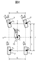
図2は、4輪車モデルを示す図である。本実施例では車両の重心点11を原点とし、車両の前後方向をx、車両の左右方向をy、車両の上下方向をzとする。図2は旋回中の4輪車の運動を示したものであり、実舵角をδ、車両の進行方向の速度をV、車両の前後方向の速度をVx、車両の左右方向の速度をVy、速度Vで旋回する車両に生じる進行方向と車体前後方向のなす角を横すべり角β、前輪右タイヤ、前輪左タイヤ、後輪右タイヤ、後輪左タイヤのそれぞれの移動速度方向とタイヤ前後方向が成す角であるタイヤの横すべり角をβfr、βfl、βrr、βrl、これらタイヤに働くコーナリングフォースをYfr、Yfl、Yrr、Yrlとする。また、重心点11を通るz軸周りに生じるヨーレートをr、重心点11と前輪軸との距離、および後輪軸との距離をそれぞれlf、lr、前輪軸と後輪軸との距離であるホイールベースをl、車両前後輪のトレッド幅をそれぞれdf、drとする。
FIG. 2 is a diagram showing a four-wheeled vehicle model. In the present embodiment, the center of
図3は、4輪車の等価的な2輪車モデルを示す図である。図3は、図2に対して左右タイヤの横すべり角が小さく、かつその値が小さく、実舵角も小さいとみなした範囲において、車両のトレッドを無視して前後の左右輪が前後輪軸と車軸との交点に集中しているモデルに置き換えたものである。ここでコーナリングフォース2Yf、2Yrは、図2に示した前後輪タイヤの左右に働くコーナリングフォースの合力である。
FIG. 3 is a diagram showing an equivalent two-wheeled vehicle model of a four-wheeled vehicle. FIG. 3 shows that the front and rear left and right wheels and the axle are ignoring the tread of the vehicle in a range in which the side slip angles of the right and left tires are small and the value is small and the actual steering angle is small. It has been replaced with a model that concentrates on the intersection with. Here, the cornering
図4は、重心点11に作用する横加速度に伴うロール運動を示す図である。図4は、横加速度Gyが作用するばね上質量mbの車両にロール角φが生じる様子を示したものである。ここで単位ロール角あたりの前後サスペンションの伸縮で生じるモーメントの大きさであるロール剛性をKφf、Kφr、車体の幾何学的な瞬間回転中心であるロールセンタの地面からの高さをhf、hr、重心点11の高さをh、前後のロールセンタを結ぶロール軸12と重心点11の間の距離をhφ、タイヤを含む前後のサスペンションのばね定数をKsf、Ksr、タイヤを含む前後のサスペンションの減衰係数をCsf、Csrとする。
FIG. 4 is a diagram showing a roll motion accompanying the lateral acceleration acting on the center of
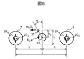
図5は、重心点11に作用する前後加速度に伴うピッチ運動を示す図である。図5は、前後加速度Gxが作用するばね上質量mbの車両にピッチ角ψが生じる様子を示したものである。ここで単位ピッチ角あたりのタイヤを含む前後のサスペンションの伸縮で生じるモーメントの大きさであるピッチ剛性をKψ、車体の幾何学的な瞬間回転中心であるピッチ軸13と重心点11の間の距離をhψとする。
FIG. 5 is a diagram showing a pitch motion accompanying the longitudinal acceleration acting on the center of
ここで図1に示した状態量推定部23における状態量推定の一例として、まず図3に示した4輪車の等価的な2輪車モデルを用いた車体の横すべり角βと横方向速度Vyの算出方法を説明する。横方向速度Vyの時間微分であるdVy/dtとz軸周りに生じるヨーレートrの時間微分であるdr/dtは、車両の質量をm、前後タイヤの単位横すべり角あたりのコーナリングフォースであるコーナリングパワーをそれぞれKf、Kr、車両のヨー慣性モーメントをIzとして、以下の式(1)、式(2)で表される。
Here, as an example of the state quantity estimation in the state
更にヨーレートrの出力偏差をフィードバックするオブザーバを構成し、式(1)、式(2)を状態方程式と出力方程式で表すと以下の式(3)、式(4)になる。 Further, an observer that feeds back the output deviation of the yaw rate r is configured, and the following equations (3) and (4) are obtained by expressing the equations (1) and (2) by a state equation and an output equation.
であり、(Vy^,r^)は,(Vy,r)の推定値である。オブザーバでは偏差eが減少するようにオブザーバ入力が補正され、状態量の推定誤差が低減される。この式(3)、式(4)から横方向速度の推定値Vy^が得られ、車体の横すべり角の推定値β^は以下の式(5)を用いて算出できる。 And (V y ^, r ^) is an estimated value of (V y , r). In the observer, the observer input is corrected so that the deviation e decreases, and the estimation error of the state quantity is reduced. The estimated value V y横 of the lateral speed is obtained from the formulas (3) and (4), and the estimated value β ^ of the side slip angle of the vehicle body can be calculated using the following formula (5).
次に図4に示した重心点11に作用する横加速度Gyに伴うロール運動モデルを用いた車体のロール角φの算出方法と、図5に示した重心点11に作用する前後加速度Gxに伴うピッチ運動モデルを用いた車体のピッチ角ψの算出方法の一例を説明する。車両が一定の加速度を持ち、重心点11に一定の慣性力が働いていると仮定した場合、ロール角φとピッチ角ψは重力加速度をgとして、以下の式(6)、式(7)で表される方程式を用いて算出できる。
Then the method for calculating the vehicle body roll angle φ using a roll motion model with the lateral acceleration G y acting on the center-of-
以上の式(1)〜式(7)において、車両の質量m、ばね上質量mb、重心点11と前輪軸との距離、および後輪軸との距離lf、lr、車両のヨー慣性モーメントIz、コーナリングパワーKf、Kr、ロール剛性Kφf、Kφr、ピッチ剛性Kψ、前後のロールセンタを結ぶロール軸12と重心点11の間の距離hφ、車体の幾何学的な瞬間回転中心であるピッチ軸13と重心点11の間の距離hψはパラメータであり、それ以外の前後加速度Gxやヨーレートrなどは図1で述べた検出値である。
In formulas (1) to (7) above, the mass m of the vehicle, the sprung mass m b, the distance between the center of
これらのパラメータには従来、車両設計時の走行試験や数値解析の結果などに基づいて、経年劣化や環境変化などに対応するロバスト性を考慮した値が定義され、定数として状態量推定などに用いられている。しかし、ロバスト性を考慮した定数であるため、常に推定誤差が生じるという課題があった。それに対して本発明では、このパラメータを変数として扱い、図1で述べた外界認識手段2の検出値に基づいて実車に即した値に更新することで推定誤差を低減し、前記課題を解決する。 Conventionally, based on the results of running tests and numerical analysis at the time of vehicle design, these parameters have been defined as values that take into account robustness corresponding to aging and environmental changes, and are used as constants for estimating state quantities. Has been. However, there is a problem that an estimation error always occurs because the constant is a value considering the robustness. On the other hand, in the present invention, this parameter is treated as a variable, and the estimation error is reduced by updating the parameter to a value suitable for the actual vehicle based on the detection value of the external recognition means 2 described in FIG. .
次に、パラメータ更新部22におけるパラメータ算出方法の一例を説明する。図6は、車両に質量mpの質点16が加わることによって重心点が14から15へ移動した様子を示す図である。なお、本実施例では理解が容易になるように、車体のロール角φが生じない位置に質点16が作用しているものと仮定した一例であり、より詳細に荷重移動を算出する場合には車体のロール角φを考慮することが望ましい。また、本実施例では車両設計時の走行試験や数値解析の結果などに基づくパラメータを設計値、更新パラメータを更新値とし、以降で述べる式の’が付く記号は更新値とする。ここでlf’、lr’は重心点(更新値)15と前輪軸との距離、および後輪軸との距離、xGは重心点(設計値)14と重心点(更新値)15との距離、xPは質点16と重心点(更新値)15との距離である。
Next, an example of a parameter calculation method in the
まず、検出値に基づいて車両の質量mとばね上質量mbを算出する方法を説明する。 First, a method of calculating the mass m and the sprung mass m b of the vehicle based on the detected value.
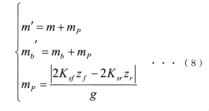
ばね定数などのサスペンション関連のパラメータが変化しておらず、タイヤを含む前後のサスペンションのばね定数Ksf、Ksrを線形ばねと仮定した場合、車両の質量とばね上質量の更新値m’、mb’は、以下の式(8)で表される方程式を用いて算出できる。 If the suspension-related parameters such as the spring constant have not changed and the spring constants K sf and K sr of the suspension before and after including the tire are assumed to be linear springs, the updated value m ′ of the mass of the vehicle and the sprung mass, mb ′ can be calculated using the equation represented by the following equation (8).
ここで式(8)のm、mbは車両の質量とばね上質量の設計値、mPは質点16の質量、zf、zrはそれぞれ車体の前側、後側の上下変位であり、以下の式(9)で表される方程式を用いて算出できる。
Here m, m b is the mass and the sprung mass of the design value of the vehicle of the formula (8), m P is the mass of
ここで式(9)のピッチ角ψは、外界認識手段2で検出した車両運動状態量検出値200である。また、式(9)のlf’、lr’は、図6に示す重心点(更新値)15と前輪軸との距離、および後輪軸との距離の更新値であり、以下の式(10)で表される方程式を用いて算出できる。
Here, the pitch angle の in the equation (9) is the vehicle motion state amount detection value 200 detected by the external world recognition means 2. In addition, l f ′ and l r ′ in equation (9) are updated values of the distance between the center of gravity (updated value) 15 shown in FIG. 6 and the front wheel axle, and the distance between the center of
ここで式(10)は車速Vが0とみなせるほどの低速で旋回している時に成立し、車体の横すべり角βは外界認識手段2で検出した車両運動状態量検出値200、実舵角δはドライバ入力量検出値の換算値である。以上の式(8)〜式(10)を用いることで、車両の質量とばね上質量の更新値m’、mb’を算出できる。 Here, equation (10) is satisfied when the vehicle is turning at a low speed enough to consider the vehicle speed V to be 0. The vehicle sideslip angle β is obtained by detecting the vehicle motion state quantity 200 detected by the external recognition means 2 and the actual steering angle δ. Is a converted value of the driver input amount detection value. By using the above equations (8) to (10), the updated values m ′ and mb ′ of the vehicle mass and the sprung mass can be calculated.
但し、この算出方法は車体の質量変化に伴ってピッチ角ψが変化することが前提であり、車内の人や荷物の質量および位置によってはそれらが変化せず、式(8)〜式(10)だけでは正しい質量を算出できない場合が考えられる。そのため、以下の式(11)で表される方程式を用いて算出する方法を併用することが望ましい。ここで式(11)のTはタイヤ出力トルク、Rはタイヤ半径である。なお、タイヤ出力トルクTは、例えばエンジンやモータのトルクマップ、変速機の変速比、効率などから算出する方法や、トルクセンサを用いて駆動軸のトルクを直接検出する方法により取得できる。なお、式(11)を併用した場合、車両の質量とばね上質量の更新値m’、mb’がそれぞれ2つ算出されるが、ピッチ角ψが変化する場合にはそれらの値は等しくなり、ピッチ角ψが変化しない場合には式(11)による更新値が式(8)〜式(10)による更新値より大きくなるため、値が大きい方を選定することで正しい車両の質量とばね上質量の更新値m’、mb’を算出できる。 However, this calculation method is based on the premise that the pitch angle 変 化 changes in accordance with the change in the mass of the vehicle body, and does not change depending on the mass and position of the people and luggage in the vehicle. ) Alone may not be able to calculate the correct mass. Therefore, it is desirable to use a method of calculating using the equation represented by the following equation (11). Here, T in the equation (11) is a tire output torque, and R is a tire radius. The tire output torque T can be obtained by, for example, a method of calculating from a torque map of an engine or a motor, a speed ratio of a transmission, efficiency, or the like, or a method of directly detecting the torque of the drive shaft using a torque sensor. When equation (11) is used together, two updated values m ′ and mb ′ of the vehicle mass and the sprung mass are respectively calculated, but when the pitch angle 変 化 changes, the values are equal. When the pitch angle し な い does not change, the updated value obtained by the equation (11) becomes larger than the updated value obtained by the equations (8) to (10). updated value of the sprung mass m ', m b' can be calculated.
ここで、外界認識手段2の検出値を用いた車両の質量とばね上質量の更新値m’、mb’の算出方法は、上記で述べた方法に限定されるものではなく、例えばサスペンションジオメトリを考慮した外界認識手段2の検出値と車両の質量とばね上質量の更新値m’、mb’の関係を表す特性マップを予め車両状態量推定装置1に記憶しておき、その特性マップに外界認識手段2の検出値を入力することで車両の質量とばね上質量の更新値m’、mb’を算出しても良い。更に、前記特性マップに加速度の軸を追加することで、路面傾斜による重力加速度の影響を除去した車両の質量とばね上質量の更新値m’、mb’を算出できる。
Here, the method of calculating the updated values m ′ and mb ′ of the mass of the vehicle and the sprung mass using the detection values of the external world recognition means 2 is not limited to the method described above. Is stored in the vehicle state
次に、検出値に基づいて重心高さhやロール軸12と重心11の間の距離hφなどの重心位置を算出する方法を説明する。
Next, a method of calculating the position of the center of gravity such as the height h of the center of gravity and the distance hφ between the
ロール剛性Kφf、Kφr、ピッチ剛性Kψなどのサスペンション関連のパラメータが変化していないと仮定した場合、ロール軸12と重心11の間の距離、ピッチ軸13と重心11の間の距離、重心高さの更新値hφ’、hψ’、h’は、以下の式(12)で表される方程式を用いて算出できる。
Roll stiffness K .phi.f, K [phi] r, assuming that the suspension-related parameters, such as pitch stiffness K [psi has not changed, the distance between the
次に検出値に基づいて図6に示す重心点(設計値)14と重心点(更新値)15との距離xG、質点16と重心点(更新値)15との距離xPを算出する方法を説明する。距離xGは重心点と後輪軸との距離の設計値lrと更新値lrの差の絶対値であり、距離xPは重心点(更新値)15を中心とした車両の質量の設計値mと質点16の質量mPによるモーメントの釣り合いより、以下の式(13)で表される方程式を用いて算出できる。
Next, based on the detected values, the distance x G between the centroid point (design value) 14 and the centroid point (update value) 15 and the distance x P between the
ここで、外界認識手段2の検出値を用いた重心高さhなどの重心位置の算出方法は、上記で述べた方法に限定されるものではなく、例えばサスペンションジオメトリを考慮した外界認識手段2の検出値と重心位置の関係を表す特性マップを予め車両状態量推定装置1に記憶しておき、その特性マップに外界認識手段2の検出値を入力することで重心位置を算出しても良い。更に、前記特性マップに加速度の軸を追加することで、路面傾斜による重力加速度の影響を除去した重心位置を算出できる。
Here, the method of calculating the position of the center of gravity such as the height h of the center of gravity using the detection value of the external world recognition means 2 is not limited to the method described above. A characteristic map representing the relationship between the detected value and the position of the center of gravity may be stored in the vehicle state
次に、検出値に基づいてヨー慣性モーメントIzなどの慣性モーメントを算出する方法を説明する。 Next, a method of calculating the moment of inertia of such a yaw inertia moment I z on the basis of the detection value.
慣性モーメントの算出方法の一例として、ヨー慣性モーメントの更新値Iz’は、平行軸の定理を用いた以下の式(14)で表される方程式で算出できる。ここで、式(14)のIzはヨー慣性モーメントの設計値である。 As an example of a method of calculating the moment of inertia, the updated value Iz 'of the yaw moment of inertia can be calculated by the following equation (14) using the parallel axis theorem. Here, I z in formula (14) is a design value of the yaw moment of inertia.
次に、検出値に基づいてコーナリングパワーKf、Krなどのタイヤ特性を算出する方法を説明する。 Next, cornering power K f, a method for calculating a tire characteristic such as K r will be described on the basis of the detection value.
タイヤ特性の算出方法の一例として、コーナリングパワーの更新値Kf’、Kr’は、以下の式(15)で表される方程式を用いて算出できる。 As an example of a method for calculating the tire characteristics, the updated cornering power values K f ′ and K r ′ can be calculated using an equation represented by the following equation (15).
ここで式(15)に示すコーナリングフォースYf、Yr、タイヤの横すべり角βf、βrは、それぞれ以下の式(16)、式(17)で表される方程式を用いて算出できる。 Here, the cornering forces Y f , Y r and the sideslip angles β f , β r of the tire shown in the equation (15) can be calculated using the equations represented by the following equations (16) and (17), respectively.
以上が本発明における車両運動状態量の推定方法、パラメータ算出方法の一例である。 The above is an example of the method of estimating the vehicle motion state quantity and the parameter calculating method according to the present invention.
前述した本発明の車両状態量推定装置1における具体的な実施形態について、図7から図13を用いて説明する。
A specific embodiment of the above-described vehicle state
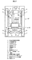
図7は、本発明の実施形態による車両状態量推定装置1を搭載した車両10の構成図を示したものである。
FIG. 7 shows a configuration diagram of a
本実施形態の車両状態量推定装置1は車両10に搭載され、カメラやGPSなどの外界認識手段2、加速度センサ3、ジャイロセンサ4、車輪速センサ6から車両運動に関する状態量、操作角センサ5からドライバ操作に関する状態量の検出値を取得する。車両状態量推定装置1は、図1で述べたように検出値を用いて外界認識手段2の安定度を判断し、その判断結果に基づいてパラメータを更新、更新したパラメータと検出値を用いて車体の横すべり角や横方向速度などを推定し、その結果を車両の制駆動力を制御する駆動制御ユニット8とブレーキ制御ユニット9に出力する。
The vehicle state
図8は、車両状態量推定装置1の処理概要を示すフローチャートである。まず、車両状態量推定装置1はパラメータ更新や状態量推定に必要な車両運動状態量およびドライバ操作量の検出値を、加速度センサ3やジャイロセンサ4などから取得する(ステップS801)。次にステップS801で取得した加速度センサ3などの検出値である車両運動状態量検出値100と、外界認識手段2の検出値である車両運動状態量検出値200を比較し、その大小関係に基づいて車両運動状態量検出値200が安定しているか否かを判断し、その安定度判断結果を出力する(ステップS802)。次にステップS802において安定判断がなされた場合、検出値に基づいて前述の式(8)〜式(18)を用いて車両の質量mやヨー慣性モーメントIzなどのパラメータを更新し、その更新パラメータを出力する(ステップS803)。最後にステップS803で更新されたパラメータと車両運動状態量検出値100、ドライバ操作量検出値に基づいて、上述の式(1)〜式(7)を用いて車体の横すべり角βや横方向速度Vy、ロール角φ、ピッチ角ψを推定し、その車両運動状態量推定値300を駆動制御ユニット8やブレーキ制御ユニット9に出力し、終了する。なお、一般的に外界認識手段2の検出値の出力周期は、加速度センサなどの慣性センサの検出値の出力周期より遅い。そのため、後述する安定度判断やパラメータ更新などにおいて、出力周期の差による誤処理を防ぐには、処理周期を最も出力周期が遅いセンサの出力周期に合わせる、または最も出力周期が遅いセンサの検出値を時間微分し、その時間微分値に基づいて予測した値を用いることが望ましい。また、燃料ゲージや着座センサ、シートベルトセンサなどから取得した情報に基づいて更新パラメータの信頼性を評価し、その評価結果に基づいてパラメータ更新を行うか否かを判断する処理をステップS803とステップS804の間に追加しても良い。
FIG. 8 is a flowchart illustrating an outline of processing of the vehicle state
図9は、車両状態量推定装置1の安定度判断部21の処理概要を示すフローチャートである。本実施例ではジャイロセンサ4で検出したヨーレートrの時間積分値であるヨー角θを真値と仮定し、その真値に対する外界認識手段2で検出したヨー角θ^の誤差に基づいて安定度を判断する方法を説明する。まず、安定度判断部21はジャイロセンサ4からヨーレートr、外界認識手段2からヨー角θ^を取得する(ステップS901)。次にステップS901で取得したヨーレートrを時間積分し、ヨー角θを算出する(ステップS902)。次にステップS902で算出したヨー角θを真値として、真値とステップS901で取得したヨー角θ^の差であるヨー角誤差を算出する(ステップS903)。次にステップS903で算出したヨー角誤差が所定の閾値に対して小さいか否かを判定し(ステップS904)、小さい場合は(ステップS904、YES)、ステップS905に進んでカウント値に所定の値を加算するカウントアップ処理を行い、大きい場合は(ステップS904、NO)、ステップS906に進んでカウント値を0にするカウントリセット処理を行う。次にステップS905でのカウントアップ処理、またはステップS906でのカウントリセット処理をしたカウント値が所定の閾値に対して大きいか否かを判定し(ステップS907)、大きい場合は(ステップS907、YES)、外界認識手段2で検出した車両運動状態量検出値200が所定の期間において継続して安定し、信頼できると判断してステップS908に進んで安定判断を出力し、小さい場合は(ステップS907、NO)、外界認識手段2で検出した車両運動状態量検出値200が所定の期間において継続して安定しておらず、信頼できないと判断してステップS909に進んで不安定判断を出力し、処理を終了する。ここでステップS901〜ステップS909における安定度を判断する方法は、上記で述べたカウントアップによる処理に限定されるものではなく、例えばカウント値から所定の値を減算するカウントダウンによる判断方法や、外界認識手段2が自己診断した情報に基づく判断方法であっても良い。また、安定度の判断対象は、上記で述べたヨー角誤差に限定されるものではなく、例えばジャイロセンサ4で検出したヨーレートrを真値とし、真値と外界認識手段2で検出したヨー角を時間微分したヨーレートr^との差であるヨーレート誤差を判断対象としても良い。
FIG. 9 is a flowchart illustrating an outline of processing of the
図10は、車両状態量推定装置1のパラメータ更新部22の処理概要を示すフローチャートである。まず、パラメータ更新部22は安定度判断部21の出力である安定度判断結果を取得する(ステップS1001)。次にステップS1001で取得した安定度判断結果が安定判断であるか不安定判断であるかを判定し(ステップS1002)、安定判断である場合は(ステップS1002、YES)、外界認識手段2の検出値にパラメータを更新するための信頼性があると判断してステップS1003に進み、不安定判断である場合は(ステップS1002、NO)、外界認識手段2の検出値にパラメータを更新するための信頼性がないと判断してパラメータの更新を行わずに処理を終了する。ステップS1002において外界認識手段2の検出値にパラメータを更新するための信頼性があると判断された場合、車両運動状態量およびドライバ操作量の検出値を、加速度センサ3やジャイロセンサ4などから取得し(ステップS1003)、ステップS1004に進む。ステップS1004〜ステップS1007では、ステップS1003で取得した検出値に基づいて、上述の式(8)〜式(17)を用いて質量、重心位置、慣性モーメント、タイヤ特性を算出し、パラメータを更新、更新したパラメータを出力して、処理を終了する。
FIG. 10 is a flowchart illustrating an outline of processing of the
ここでパラメータの更新方法は上記の方法に限定されるものではなく、例えば最適化手法やシステム同定手法を用いて走行中にセンサで取得した時系列データからパラメータを更新しても良い。また、パラメータ更新部22において更新するパラメータの値の範囲は、センサの誤検出による更新値の発散などを防ぐため、例えば質量の場合は空車時の質量を下限値、最大積載時の質量を上限値とするなど、各パラメータで変化する可能性がある範囲を予め定義し、その範囲内で更新することが望ましい。また、更新パラメータの保存形態は数値に限定せず、例えば式(16)と式(17)を用いて算出したコーナリングフォースYf、Yrとタイヤの横すべり角βf、βrに基づくタイヤ特性のマップとして保存しても良い。
Here, the parameter updating method is not limited to the above method, and the parameter may be updated from time-series data acquired by a sensor during traveling using, for example, an optimization technique or a system identification technique. In addition, in order to prevent the divergence of the updated value due to erroneous detection of the sensor, the range of the parameter value updated in the
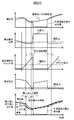
図11は、車両状態量推定装置1の検出値、検出値の誤差、安定期間のカウント値、推定値と検出値の時間変化を示す図である。検出値、検出値の誤差、安定期間のカウント値は、図9で述べた安定度判断部21における処理結果の一例である。また、推定値は図10で述べたパラメータ更新部22から出力された更新パラメータを用いて状態量推定部23が推定した結果の一例である。図11に示す安定判断期間は、検出値の誤差(Q)が閾値(a)より小さく、そのカウント値(J)が閾値(b)より大きい期間であり、外界認識手段2で検出した車両運動状態量検出値200が所定の期間において継続して安定し、信頼できるとして、安定度判断部21が安定判断を出力した期間である。パラメータ更新部22は、前記の安定判断期間内にパラメータ更新を行い、それ以外の期間(不安定判断期間)ではパラメータ更新を中止する。その結果、状態量推定部23は安定判断期間において従来方法と同様に真値と概ね等しい高精度な推定値を出力できる。更に本実施例の状態量推定部23は、安定判断期間で更新された最新のパラメータを用いて推定を行うため、不安定判断期間において外界認識手段2の検出値による推定値の補正ができない従来方法に比べて真値に近い推定値を出力することができる。このように従来方法では定数として扱っていたパラメータを変数として扱い、そのパラメータを外界認識手段2の検出値に基づいて実車に即した値に更新し、その更新したパラメータを用いて推定を行うことで従来方法より推定誤差を低減できる。
FIG. 11 is a diagram showing the detection value of the vehicle state
以上のような車両状態量推定装置1を適用した場合の効果を以下で説明する。
Effects when the above-described vehicle state
横滑り防止装置の場合、例えば設計時より低性能なタイヤに交換、またはタイヤ空気圧が低下、または磨耗したタイヤを使用した際、従来方法では横滑り防止装置の制動力指令が不足して横すべりが増大し、走行安定性が低下する恐れがあった。それに対して本実施例の車両状態量推定装置1を適用した場合、現状のタイヤ特性に基づいて横滑り防止装置の制動力指令を補正できるため、従来方法より横すべりを低減し、走行安定性を向上させることができる。
In the case of a skid prevention device, for example, when replacing a tire with lower performance than at the time of design, or when tire pressure is reduced or a worn tire is used, in the conventional method, the braking force command of the skid prevention device is insufficient and the skid increases. However, running stability may be reduced. On the other hand, when the vehicle state
また、本実施例の車両状態量推定装置1を適用した場合、真値と概ね等しい高精度な推定値が得られる、つまりドライバの操作入力に対する状態量の予測値が得られるため、その予測値に基づいて横滑り防止装置の制動力指令を補正でき、従来方法より横すべりを低減し、走行安定性を向上できる。
Further, when the vehicle state
また、パワーステアリング装置の場合、例えば設計時より低性能なタイヤに交換、またはタイヤ空気圧が低下、または磨耗したタイヤを使用した場合、従来方法ではパワーステアリング装置のアシストが変化しないため、タイヤ特性相応の車両挙動が生じていた。それに対して本実施例の車両状態量推定装置1を適用した場合、現状のタイヤ特性に応じてパワーステアリング装置のアシスト力や舵角を増減できるため、限界域を除いて純正タイヤ時や新品タイヤ時と同等の車両挙動を実現することができる。また、本実施例の車両状態量推定装置1を適用した場合、ノミナルモデルと最新パラメータの推定モデルによる推定値を比較する事でタイヤ空気圧の低下などを検出でき、ドライバに伝達する事ができる。
Also, in the case of a power steering device, for example, when replacing the tire with a lower-performance tire than at the time of design, or when using a tire with reduced tire pressure or worn tire, the assist of the power steering device does not change in the conventional method, so that the tire characteristic is not changed. Vehicle behavior occurred. On the other hand, when the vehicle state
また、電動ブースタ装置の場合、例えば設計時より低性能なタイヤに交換、またはタイヤ空気圧が低下、または磨耗したタイヤを使用した場合、従来方法では電動ブースタ装置の制動力指令が変化しないため、タイヤ特性相応の制動力が生じる。それに対して本実施例の車両状態量推定装置1を適用した場合、現状のタイヤ特性に応じて電動ブースタ装置の制動力指令を補正できるため、限界域を除いて純正タイヤ時や新品タイヤ時と同等の制動力を発生させる事ができる。
Further, in the case of an electric booster device, for example, when replacing the tire with a lower-performance tire than at the time of design, or when the tire pressure is reduced, or when a worn tire is used, the braking force command of the electric booster device does not change in the conventional method. A braking force corresponding to the characteristic is generated. On the other hand, when the vehicle state
また、電動パーキングブレーキ装置の場合、最新の質量に基づいて適切な制動力指令を生成できるため、従来方法より電力消費を削減する事ができる。 In the case of an electric parking brake device, an appropriate braking force command can be generated based on the latest mass, so that power consumption can be reduced as compared with the conventional method.
図12は、地面に固定した座標系に対する車両の重心点11の位置関係を示す図である。車両の重心点11の軌跡は、車両の重心点11の地面に固定された座標系に対する位置を(X,Y)、車両のX軸に対するヨー角をθとして、以下の式(18)で表される。
FIG. 12 is a diagram illustrating a positional relationship of the center of
ここで、X0、Y0、θ0はそれぞれt=0でのX、Y、θの値、tは任意の時間である。この式(18)は車両の進行方向の速度Vや車体の横すべり角βといった外界認識手段2の検出値、または車両モデルを用いた式(1)などで算出される推定値を用いる。また、これらの外界認識手段2の検出値や車両モデルを用いて算出した推定値を用いずに車両の重心点11の軌跡を算出するには、例えば以下の式(19)を用いる方法がある。
Here, X 0 , Y 0 , and θ 0 are the values of X, Y, and θ at t = 0, respectively, and t is an arbitrary time. The expression (18) uses a detection value of the external recognition means 2 such as the speed V in the traveling direction of the vehicle and the side slip angle β of the vehicle, or an estimated value calculated by the expression (1) using a vehicle model. In order to calculate the trajectory of the center of
図13は、低性能なタイヤへの交換やタイヤ空気圧の低下に伴ってコーナリングパワーが低下した車両の定常円旋回時の重心点11の軌跡を示す図である。真値(e)は、外界認識手段2の検出値である車両運動状態量検出値200および式(18)を用いて算出した車両の重心点11の実軌跡である。車両モデルなし(f)は、式(19)を用いて算出した車両の重心点11の推定軌跡である。車両モデルあり, パラメータ更新なし(g)は、パラメータを更新していない車両モデルを用いて算出した推定値および式(18)を用いて算出した車両の重心点11の推定軌跡である。車両モデルあり, パラメータ更新なし(h)は、パラメータを更新した車両モデルを用いて算出した推定値および式(18)を用いて算出した車両の重心点11の推定軌跡である。
FIG. 13 is a diagram showing a locus of the center of
図13に示すように車両の重心点11の実軌跡である真値(e)に対して、車両モデルあり, パラメータ更新あり(h)の推定軌跡は概ね等しいが、車両モデルなし(f)と車両モデルあり, パラメータ更新なし(g)の推定軌跡は推定誤差が大きい。
As shown in FIG. 13, the estimated trajectory with the vehicle model and the parameter update (h) is substantially equal to the true value (e), which is the actual trajectory of the center of
自動運転装置の場合、従来方法では外界認識手段の検出値に基づいて自己位置推定を行っており、雨天やレンズ汚れなどの悪条件では検出精度が低下し、自動運転が継続できなくなる恐れがあった。この外界認識手段の検出精度低下に対して、自動運転を継続する方法として、式(18)や式(19)を用いて推定した車両の軌跡などの情報に基づいてマップマッチングを行う方法が考えられるが、上記の車両モデルなし(f)や車両モデルあり, パラメータ更新なし(g)のように軌跡の推定誤差が大きい方法では安全な自動運転を継続できない恐れがあった。それに対して本実施例の車両状態量推定装置1を適用した場合、車両の軌跡などを高精度に推定できるため、少なくとも安全に停車できる場所まで自動運転を継続することができる。
In the case of an automatic driving device, in the conventional method, the self-position estimation is performed based on the detection value of the external recognition means, and in bad conditions such as rainy weather or lens contamination, the detection accuracy is reduced, and there is a possibility that the automatic driving cannot be continued. Was. As a method of continuing the automatic driving in response to the decrease in the detection accuracy of the external world recognition means, a method of performing map matching based on information such as a trajectory of a vehicle estimated using Expressions (18) and (19) is considered. However, there is a risk that safe automatic driving cannot be continued in a method having a large trajectory estimation error, such as the case without the vehicle model (f), the case with the vehicle model, and no parameter update (g). On the other hand, when the vehicle state
実施例2では、実施例1との差分について説明し、実施例1と同じ説明は省略する。 In the second embodiment, differences from the first embodiment will be described, and the same description as in the first embodiment will be omitted.
なお、実施例2と実施例1の主な違いは安定度判断部21における安定度の判断方法であり、図14と図15を用いて、実施例2における車両状態量推定装置1の処理概要を説明する。
Note that the main difference between the second embodiment and the first embodiment is a method of determining the stability in the
図14は、実施例2における車両状態量推定装置1の安定度判断部21の処理概要を示すフローチャートである。図14のステップS1401〜ステップS1403の処理は、実施例1における図9のステップS901〜ステップS903と同じであり、説明は省略する。ステップS1404では、ステップS1403で算出したヨー角誤差を所定の期間で時間積分した値を算出する。次にステップS1404で算出したヨー角誤差の積分値が所定の閾値に対して小さいか否かを判定し(ステップS1405)、小さい場合は(ステップS1405、YES)、外界認識手段2で検出した車両運動状態量検出値200が所定の期間において継続して安定し、信頼できると判断してステップS1406に進んで安定判断を出力し、大きい場合は(ステップS1405、NO)、外界認識手段2で検出した車両運動状態量検出値200が所定の期間において継続して安定しておらず、信頼できないと判断してステップS1407に進んで不安定判断を出力し、処理を終了する。ここでステップS1404、ステップS1405における安定度の判断方法は、上記で述べた積分値による判断方法に限定されるものではなく、例えば平均値による判断方法であっても良い。
FIG. 14 is a flowchart illustrating an outline of a process performed by the
図15は、実施例2における車両状態量推定装置1の検出値、検出値の誤差、検出値の誤差の積分値、推定値と検出値の時間変化を示す図である。図15に示す安定判断期間は、検出値の誤差(Q)を所定の期間で積分した積分値(N)が閾値(c)より小さい期間であり、外界認識手段2で検出した車両運動状態量検出値200が所定の期間において継続して安定し、信頼できるとして、安定度判断部21が安定判断を出力した期間である。図15の検出値と検出値の誤差に示す閾値(a)を超過する瞬間的なノイズは、実際の車両の使用環境下において生じる可能性がある。このようなノイズが生じた場合、実施例1における車両状態量推定装置1ではカウント値がリセットされ、パラメータ更新が中止される。それに対して実施例2における車両状態量推定装置1では、ノイズの大きさが小さく、積分値(N)が閾値(c)より小さくなる期間を安定判断期間とすることで、実際の車両の使用環境下において、パラメータの更新にある一定の精度を確保しながら、パラメータの更新頻度を増やすことができる。
FIG. 15 is a diagram illustrating a detection value, an error of the detection value, an integral value of the error of the detection value, and a temporal change of the estimation value and the detection value of the vehicle state
実施例3では、実施例1および実施例2との差分について説明し、実施例1および実施例2と同じ説明は省略する。 In the third embodiment, the difference between the first and second embodiments will be described, and the same description as in the first and second embodiments will be omitted.
なお、実施例3と実施例1および実施例2の主な違いは、パラメータ更新部22におけるパラメータの更新/未更新の判断方法であり、図16と図17を用いて、実施例3における車両状態量推定装置1の処理概要を説明する。
The main difference between the third embodiment, the first embodiment, and the second embodiment is a method of determining whether the parameter is updated / not updated in the
図16は、実施例3における車両状態量推定装置1のパラメータ更新部22の処理概要を示すフローチャートである。まず、実施例3のパラメータ更新部22は、1処理周期前の外界認識手段2で検出した車両運動状態量検出値200と、状態量推定部23で推定した推定値を取得する(ステップS1601)。ここで本実施例では、図8で述べた車両状態量推定装置1の処理概要を示すフローチャートのSTARTからENDまでを1処理として定義する。次にステップS1601で取得した検出値、推定値の差である推定誤差を算出する(ステップS1602)。次にステップS1602で算出した推定誤差が所定の閾値に対して大きいか否かを判定し(ステップS1603)、大きい場合は(ステップS1603、YES)、推定値の精度が不十分と判断してステップS1604に進み、小さい場合は(ステップS1603、NO)、推定値の精度が必要十分であり、パラメータの更新は不要と判断して処理を終了する。ステップS1604では、図10で述べたフローに従ってパラメータを更新し、処理を終了する。
FIG. 16 is a flowchart illustrating an outline of processing of the
図17は、実施例3における車両状態量推定装置1の検出値、検出値の誤差、安定期間のカウント値、推定誤差、推定値と検出値の時間変化を示す図である。図17に示すように、安定判断期間であっても推定誤差が所定の閾値(d)より小さい場合にはパラメータ更新を中止する。このように推定誤差の大きさに基づいてパラメータの更新/未更新を判断することで、ある一定の推定精度を確保しながら、車両状態量推定装置1の計算負荷を下げることができ、消費電力や発熱などを低減できる。
FIG. 17 is a diagram illustrating a detection value, an error of a detection value, a count value of a stable period, an estimation error, and a temporal change of the estimation value and the detection value of the vehicle state
実施例4では、実施例1〜実施例3との差分について説明し、実施例1〜実施例3と同じ説明は省略する。 In the fourth embodiment, differences from the first to third embodiments will be described, and the same description as the first to third embodiments will be omitted.
なお、実施例4と実施例1〜実施例3の主な違いは、実施例1〜実施例3の車両状態量推定装置1に出力値判断部24を追加した車両状態量出力装置30を構成したことであり、図18〜図20を用いて実施例4における車両状態量出力装置30の処理概要を説明する。
The main difference between the fourth embodiment and the first to third embodiments is that the vehicle state
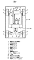
図18は、実施例4における車両状態量出力装置30の概念図である。図18に示すように、車両状態量出力装置30は実施例1〜実施例3の車両状態量推定装置1に出力値判断部24を追加した構成になっている。出力値判断部24は、状態量推定部23の出力である車両運動状態量推定値300と、安定度判断部21の出力である安定度判断結果と、外界認識手段2で検出した車両運動状態量検出値200に基づいて、車両運動状態量推定値300と車両運動状態量検出値200のどちらを車両運動状態量出力値400として出力するかを判断する。ここで、図18には車両運動状態量出力値400のみを出力する場合を記載しているが、必要に応じて安定度判断結果や更新パラメータ、車両運動状態量推定値300を出力しても良く、車両状態量出力装置30の出力値は限定しない。
FIG. 18 is a conceptual diagram of the vehicle state
図19は、実施例4における車両状態量出力装置30の出力値判断部24の処理概要を示すフローチャートである。まず、出力値判断部24は安定度判断部21の出力である安定度判断結果を取得する(ステップS1901)。次にステップS1901で取得した安定度判断結果が安定判断であるか不安定判断であるかを判定し(ステップS1902)、安定判断である場合は(ステップS1902、YES)、外界認識手段2の検出値にパラメータを更新するための信頼性があると判断してステップS1903に進み、不安定判断である場合は(ステップS1902、NO)、外界認識手段2の検出値にパラメータを更新するための信頼性がないと判断してステップS1907に進み、推定値を出力して処理を終了する。ステップS1902において外界認識手段2の検出値にパラメータを更新するための信頼性があると判断された場合、1処理周期前の外界認識手段2で検出した車両運動状態量検出値200と、状態量推定部23で推定した推定値を取得する(ステップS1903)。ここで本実施例では、実施例1の図8で述べた車両状態量推定装置1の処理概要を示すフローチャートのSTARTからENDまでを1処理として定義する。次にステップS1903で取得した検出値、推定値の差である推定誤差を算出する(ステップS1904)。次にステップS1904で算出した推定誤差が所定の閾値に対して大きいか否かを判定し(ステップS1905)、大きい場合は(ステップS1905、YES)、推定値の精度が不十分と判断してステップS1906に進んで検出値を出力し、小さい場合は(ステップS1905、NO)、推定値の精度が必要十分であると判断してステップS1907に進んで推定値を出力し、処理を終了する。
FIG. 19 is a flowchart illustrating an outline of a process performed by the output
図20は、実施例4における車両状態量出力装置30の検出値、検出値の誤差、安定期間のカウント値、推定誤差、推定値と検出値と出力値の時間変化を示す図である。図20に示すように車両状態量出力装置30は、安定判断期間であり、かつ推定誤差が閾値(d)より大きい場合には検出値を出力値として出力し、それ以外では推定値を出力値として出力する。このように安定度判断結果および推定誤差の大きさに基づいて、車両状態量出力装置30から出力する出力値を判断することで、車両状態量出力装置30の中で真値に最も近い値を出力することができる。
FIG. 20 is a diagram illustrating the detection value, the error of the detection value, the count value of the stable period, the estimation error, and the temporal change of the estimation value, the detection value, and the output value of the vehicle state
実施例5では、実施例1〜実施例4との差分について説明し、実施例1〜実施例4と同じ説明は省略する。 In the fifth embodiment, differences from the first to fourth embodiments will be described, and the same description as in the first to fourth embodiments will be omitted.
なお、実施例5と実施例1〜実施例4の主な違いは、実施例1〜実施例4の車両10にサスペンション制御ユニット40と制御サスペンション装置41を追加した車両10’を構成したことであり、図21〜図24を用いて主に実施例5におけるサスペンション制御ユニット40の処理概要を説明する。なお、実施例5における車両状態量推定装置1は、車両状態量出力装置30であっても良い。
The main difference between the fifth embodiment and the first to fourth embodiments is that a vehicle 10 'in which a
図21は、実施例5における車両状態量推定装置1あるいは車両状態量出力装置30を搭載した車両10’の構成図を示したものである。図21は、図7に対してサスペンション制御ユニット40と制御サスペンション装置41を追加した構成になっている。制御サスペンション装置41は、減衰特性を調整可能な減衰力調整式のショックアブソーバあるいは車体と車輪の間の上下方向の力を調整可能なアクティブサスペンションである。サスペンション制御ユニット40は、慣性センサやジャイロセンサなどの検出値や車両状態量推定装置1で更新した質量や重心位置などの更新パラメータに基づいて、乗心地制御やアンチロール制御などに必要な車両状態量を推定し、制御サスペンション装置41の減衰特性あるいは上下方向の力を制御する制御信号を生成する。
FIG. 21 shows a configuration diagram of a
次に図22〜図24を用いて車両状態量推定装置1で更新した更新パラメータを用いたサスペンション制御ユニット40における乗心地制御、アンチロール制御、アンチダイブ・アンチスクワット制御の処理概要を説明する。
Next, a processing outline of the ride comfort control, the anti-roll control, and the anti-dive / anti-squat control in the
図22は実施例5における制御サスペンション装置41の1機能である乗心地制御を行うサスペンション制御ユニット40の概念図である。サスペンション制御ユニット40には、車両状態量推定装置1で更新された質量や重心位置などの更新パラメータや、慣性センサで検出したばね上上下加速度やばね下上下加速度などの車両運動状態量検出値100が入力される。
FIG. 22 is a conceptual diagram of a
サスペンション制御ユニット40は、上下速度推定部43と、目標減衰力算出部44と、減衰力マップ45を備える。
The
上下速度推定部43は、車両状態量推定装置1の更新パラメータと車両運動状態量検出値100を入力として、ばね上およびばね下の上下速度を推定する。
The vertical
目標減衰力算出部44は、上下速度推定部42で推定した上下速度と車両運動状態量検出値100に基づいて、制御サスペンション装置41の目標減衰力を算出する。
The target damping
減衰力マップ45は、予め記憶された制御サスペンション装置41の特性のマップ情報であり、目標減衰力算出部44で算出した目標減衰力と車両運動状態量検出値100を入力として、制御サスペンション装置41を制御する指令電流を導出し、出力する。
The damping
図23は実施例5における制御サスペンション装置41の1機能であるアンチロール制御を行うサスペンション制御ユニット40の概念図である。サスペンション制御ユニット40には、車両状態量推定装置1で更新された質量や重心位置などの更新パラメータや、慣性センサで検出したばね上上下加速度やばね下上下加速度などの車両運動状態量検出値100、舵角センサで検出した操舵角などのドライバ入力量検出値が入力される。
FIG. 23 is a conceptual diagram of a
サスペンション制御ユニット40は、主に車両運動モデル46と、予め記憶されたロール制御ゲイン、ピッチ制御ゲインを備える。
The
車両運動モデル46は、車両状態量推定装置1の更新パラメータと、車両運動状態量検出値100と、ドライバ入力量検出値を入力として車両の横加速度を推定する。
The
サスペンション制御ユニット40は、車両運動モデル46で推定した横加速度を微分した横加加速度とロール制御ゲイン、車両運動モデル46で推定した横加速度の絶対値とピッチ制御ゲインに基づいて、制御サスペンション装置41を制御する指令電流を算出し、出力する。
The
図24は実施例5における制御サスペンション装置41の1機能であるアンチダイブ制御およびアンチスクワット制御を行うサスペンション制御ユニット40の概念図である。サスペンション制御ユニット40には、車両状態量推定装置1で更新された質量や重心位置などの更新パラメータと、ブレーキマスタシリンダ圧やエンジントルク、ギア位置などの車両運動状態量検出値100が入力される。
FIG. 24 is a conceptual diagram of a
サスペンション制御ユニット40は、主に車両運動モデル46と、予め記憶されたピッチ制御ゲインを備える。
The
車両運動モデル46は、車両状態量推定装置1の更新パラメータと、車両運動状態量検出値100を入力として車両の前後加速度を推定する。
The
サスペンション制御ユニット40は、車両運動モデル46で推定した前後加速度を微分した前後加加速度とピッチ制御ゲインに基づいて、制御サスペンション装置41を制御する指令電流を算出し、出力する。
The
図25と図26は実施例5における更新パラメータを入力とした効果を示すシミュレーションの結果の一例である。図25と図26は共に高速うねり路において更新パラメータである質量の更新有無が乗心地に与える影響を比較した結果であり、図25はフロア、Frタワー、Rrタワーの上下加速度PSD、図26はフロア上下変位、ピッチ角、ロール角の時間変化を示す図である。図25と図26に示すようにパラメータ更新あり(本発明)は、予め記憶したロバスト性を考慮した設計時のパラメータを用いたパラメータ更新なし(従来方法)に対して、特にRrタワーの上下加速度PSDとピッチ角が小さくなっており、より高性能な乗心地制御が実現できる。 FIG. 25 and FIG. 26 are examples of simulation results showing the effect of inputting update parameters in the fifth embodiment. FIGS. 25 and 26 show the results of comparing the influence of the update of the mass, which is the update parameter, on the riding comfort on a high-speed undulating road. FIG. 25 shows the vertical acceleration PSD of the floor, the Fr tower, and the Rr tower, and FIG. It is a figure which shows the time change of a floor vertical displacement, a pitch angle, and a roll angle. As shown in FIG. 25 and FIG. 26, the parameter update (in the present invention) is more effective than the parameter update using the parameter at the time of design in consideration of the previously stored robustness (the conventional method). Since the PSD and the pitch angle are small, higher-performance riding comfort control can be realized.
以上の構成により、最新の質量や重心位置などのパラメータを用いて高精度に推定したばね上上下速度や横加速度などの車両状態量に基づいてサスペンションを制御する指令電流を生成できるため、従来の予め記憶したロバスト性を考慮した設計時のパラメータを用いた場合より高性能なサスペンション制御を実現できる。また、質量や重心位置などが影響する予め記憶された減衰力マップやロール制御ゲイン、ピッチ制御ゲインは、最新の質量や重心位置などのパラメータを用いて更新することが望ましい。 With the above configuration, it is possible to generate a command current for controlling the suspension based on vehicle state quantities such as sprung vertical velocity and lateral acceleration estimated with high accuracy using the latest parameters such as mass and center of gravity. Higher-performance suspension control can be realized as compared with the case where parameters at the time of design in consideration of robustness stored in advance are used. In addition, it is desirable to update the previously stored damping force map, roll control gain, and pitch control gain, which are affected by the mass and the position of the center of gravity, using the latest parameters such as the mass and the position of the center of gravity.
実施例6では、実施例5との差分について説明し、実施例5と同じ説明は省略する。 In the sixth embodiment, differences from the fifth embodiment will be described, and the same description as in the fifth embodiment will be omitted.
なお、実施例6と実施例5の主な違いは、実施例5の車両10’に車高センサ42を追加した車両10”を構成したことであり、図27〜図28を用いて主に実施例6におけるサスペンション制御ユニット40の処理概要を説明する。
Note that the main difference between the sixth embodiment and the fifth embodiment is that a
図27は、実施例6における車両状態量推定装置1あるいは車両状態量出力装置30を搭載した車両10”の構成図を示したものである。図27は、図21に対して車高センサ42を追加した構成になっている。
FIG. 27 is a diagram showing a configuration of a
車高センサ42は、路面と車体の相対的なz軸方向の距離、あるいは車両のサスペンションの変位量を検出する。サスペンション制御ユニット40は、車高センサ42などの各種センサの検出値や車両状態量推定装置1あるいは車両状態量出力装置30の更新パラメータに基づいて制御サスペンション装置41の減衰特性あるいは上下方向の力を制御する。車高センサ42は、車体の右前側、左前側、右後側、左後側の上下変位zfr、zfl、zrr、zrlを直接検出することができるため、車両の質量とばね上質量の更新値m’、mb’は、以下の式(20)で表される方程式を用いて算出できる。
The
一般的に外界認識手段2で検出したピッチ角ψなどに基づいて算出した上下変位に比べて、車高センサ42は上下変位を直接検出できるために精度が高く、車両状態量推定装置1あるいは車両状態量出力装置30において高精度なパラメータ更新と、それを用いた高性能なサスペンション制御を実現できる。また、質量や重心位置、慣性モーメントは外界認識手段2および車高センサ42の検出値から算出できるため、これらのパラメータに関してはどちらか一方が故障した場合であっても車両状態量推定装置1あるいは車両状態量出力装置30によるパラメータ更新を継続することができる。
In general, the
図28は、質量mPの質点が作用する車両に生じる上下変位を示す図である。図28は、質量mPの質点が作用する車体の右前側、左前側、右後側、左後側の上下変位zfr、zfl、zrr、zrlが生じる様子を示したものである。この車体の上下変位を用いて、車体のロール角φとピッチ角ψは、以下の式(21)で表される方程式を用いて算出できる。ここで本実施例では理解を容易にするために、車両前後輪のトレッド幅が等しいdと仮定する。 FIG. 28 is a diagram illustrating vertical displacement that occurs in a vehicle on which a mass point of mass m P acts. FIG. 28 shows a manner in which a vertical displacement z fr , z fl , z rr , z rl on the right front side, the left front side, the right rear side, and the left rear side of the vehicle body on which the mass point of mass m P acts. . Using this vertical displacement of the vehicle body, the roll angle φ and the pitch angle の of the vehicle body can be calculated using an equation represented by the following equation (21). Here, in this embodiment, in order to facilitate understanding, it is assumed that the tread width of the front and rear wheels of the vehicle is equal to d.
この式(21)を用いて算出したロール角φとピッチ角ψを外界認識手段2の検出値と比較することで、センサ故障の有無や検出値の信頼性を判断することができる。
By comparing the roll angle φ and the pitch angle ψ calculated using this equation (21) with the detection value of the external
実施例7では、実施例5および実施例6との差分について説明し、実施例5および実施例6と同じ説明は省略する。なお、実施例7と実施例5および実施例6の主な違いは、サスペンション制御ユニット40で算出したタイヤの接地荷重に基づいて、車両状態量推定装置1がパラメータ更新の可否を判断することであり、図29〜図33を用いて、主に実施例7におけるサスペンション制御ユニット40と車両状態量制御装置1あるいは車両状態量出力装置30の処理概要を説明する。
In the seventh embodiment, differences from the fifth and sixth embodiments will be described, and the same description as in the fifth and sixth embodiments will be omitted. The main difference between the seventh embodiment, the fifth embodiment, and the sixth embodiment is that the vehicle state
図29は、実施例7における車両状態量推定装置1’の概念図である。図29に示すように、車両状態量推定装置1’は実施例1〜実施例3の車両状態量推定装置1のパラメータ更新部22にサスペンション制御ユニット40で算出したタイヤの接地荷重計算値を入力する構成になっている。なお、式(15)などで述べたコーナリングパワーKf、Krは接地荷重によって大きさが変化するため、車両運動状態量推定値300の推定精度を向上させるためには接地荷重計算値を状態量推定部23に入力する構成にすることが望ましい。また、接地荷重計算値は実施例4の車両状態量出力装置30のパラメータ更新部22に入力する構成であっても良い。
FIG. 29 is a conceptual diagram of a vehicle state quantity estimation device 1 'according to the seventh embodiment. As shown in FIG. 29, the vehicle state
次にサスペンション制御ユニット40におけるタイヤの接地荷重計算値の推定方法を説明する。
Next, a method of estimating the calculated value of the ground contact load of the tire in the
図30は、1自由度の1/4車両モデルを示す図である。図30は、質量mtのばね下上下変位ztによって質量mbのばね上が上下変位する様子を示したものである。ここでサスペンションのばね定数をKs、サスペンションの減衰係数をCs、ばね上の上下変位をzb、ばね下の上下変位をzt、タイヤの接地荷重をW0とする。ばね上およびばね下の運動は、それぞれ以下の式(22)、式(23)で表される。 FIG. 30 is a diagram illustrating a 車 両 vehicle model with one degree of freedom. Figure 30 is one in which the sprung mass m b showed how the vertical displacement by the unsprung vertical displacement z t of the mass m t. Here, the spring constant of the suspension is K s , the damping coefficient of the suspension is C s , the vertical displacement above the spring is z b , the vertical displacement below the spring is z t , and the ground contact load of the tire is W 0 . The sprung and unsprung motions are represented by the following equations (22) and (23), respectively.
ここで式(22)、式(23)のサスペンションの減衰係数Csには、制御サスペンション装置41が減衰特性を調整可能な減衰力調整式のショックアブソーバの場合はサスペンション制御ユニット40の指令電流に基づく減衰係数を入力する。また、車体と車輪の間の上下方向の力を調整可能なアクティブサスペンションの場合には、式(22)、式(23)の右辺をサスペンション制御ユニット40で導出した上下方向の力に置き換える。また、d2zb/dt2、d2zt/dt2は、ばね上およびばね下に設置した上下加速度センサの検出値およびそれらに基づく推定値に限定されるものではなく、例えば加速度センサ3や車高センサ42などの検出値に基づく推定値であっても良い。
Here Equation (22), the suspension damping coefficient C s of formula (23), when controlled
式(23)のΔW0は接地荷重の変動分であり、接地荷重W0は静止時の接地荷重にこの変動分を加算した以下の式(24)で表される。 ΔW 0 in the equation (23) is a variation of the contact load, and the contact load W 0 is represented by the following equation (24) in which the variation is added to the contact load at rest.
以上の方法により、タイヤの接地荷重を算出することができる。 With the above method, the contact load of the tire can be calculated.
図31は、実施例7における車両状態量推定装置1’のパラメータ更新部22の処理概要を示すフローチャートである。図31に示すフローチャートでは、パラメータを補正するにあたって、接地荷重変動周波数と接地荷重変動差の算出を行う。この接地荷重変動周波数と接地荷重変動差は、荒れた路面によって生じる接地荷重の振動や路面のくぼみによって生じる接地荷重の抜けなどのパラメータを補正する補正ゲインを導出するために算出する。まず、図31の説明に先立ち、図31の理解が容易になるように、図32、図33を用いて接地荷重変動差の算出方法について説明する。
FIG. 31 is a flowchart illustrating an outline of a process performed by the
図32は、重心点11に作用する加速度に伴う荷重移動を示す図である。図32は、前後加速度Gxと横加速度Gyが作用するばね上質量mbの車両の各タイヤに接地荷重の変動量ΔWfl、ΔWfr、ΔWrl、ΔWrrが生じる様子を示したものである。なお、図32は理解が容易になるように、車体のロール角φおよびピッチ角ψが生じないと仮定した一例であり、より詳細に荷重移動を算出する場合には車体のロール角φおよびピッチ角ψに伴う荷重移動を考慮することが望ましい。
FIG. 32 is a diagram illustrating a load movement accompanying acceleration acting on the center of
図33は、カント角σのバンク路を走行する車両の重心点11に作用する加速度を示す図である。なお、図33は理解が容易になるように、車体のロール角φおよび車両の横すべり角βなどが生じないと仮定した一例であり、より詳細に荷重移動を算出する場合にはそれらを考慮して荷重移動を計算することが望ましい。
FIG. 33 is a diagram showing acceleration acting on the center of
図32、図33に示したモデルを用いて、各タイヤの接地荷重の変動量ΔWfl、ΔWfr、ΔWrl、ΔWrrの算出方法の一例を説明する。車両が一定の加速度を持ち、重心点11に一定の慣性力が働いていると仮定した場合、接地荷重変動量の推定値ΔWfl、ΔWfr、ΔWrl、ΔWrrは、以下の式(25)で表される。
An example of a method of calculating the variation amounts ΔW fl , ΔW fr , ΔW rl , and ΔW rr of the ground contact load of each tire will be described using the models shown in FIGS. Assuming that the vehicle has a constant acceleration and a constant inertial force is acting on the center of
ここで式(25)の右辺第一項は前後加速度Gxに伴う接地荷重変動量、右辺第二項は左右加速度Gyに伴う接地荷重変動量、右辺第三項はカント角σによって生じる上下加速度の変化に伴う接地荷重変動量である。また、式(25)で用いるカント角σは、以下の式(26)で表される方程式で算出できる。 Here, the first term on the right side of the equation (25) is the variation in the contact load associated with the longitudinal acceleration Gx, the second term on the right is the variation in the contact load associated with the lateral acceleration Gy, and the third term on the right is the vertical acceleration caused by the cant angle σ. This is the amount of change in the contact load due to the change. Further, the cant angle σ used in the equation (25) can be calculated by an equation represented by the following equation (26).
次に接地荷重変動差ΔWFY、ΔWRY、ΔWLX、ΔWRXは、サスペンション制御ユニット40から入力された最新の接地荷重をWfl、Wfr、Wrl、Wrr、最新の静止時の接地荷重をWfl0、Wfr0、Wrl0、Wrr0として、式(25)、式(26)から算出した接地荷重変動量の推定値ΔWfl、ΔWfr、ΔWrl、ΔWrrを用いて、以下の式(27)で表される。
Next, the ground contact load fluctuation differences ΔW FY , ΔW RY , ΔW LX , and ΔW RX calculate the latest ground load input from the
ここで式(27)の第一式は前輪左右の接地荷重変動量の計算値と推定値の差、第二式は後輪左右の接地荷重変動量の計算値と推定値の差、第三式は左輪前後の接地荷重変動量の計算値と推定値の差、第四式は右輪前後の接地荷重変動量計算値と推定値の差である。 Here, the first expression of Expression (27) is the difference between the calculated value and the estimated value of the front-wheel left and right contact load fluctuation amount, the second expression is the difference between the calculated value of the rear-wheel left and right contact load fluctuation amount and the estimated value, The equation is the difference between the calculated value of the ground contact load fluctuation before and after the left wheel and the estimated value, and the fourth equation is the difference between the calculated value of the ground load fluctuation before and after the right wheel and the estimated value.
図31に戻り、実施例7における車両状態量推定装置1’のパラメータ更新部22の処理概要を示すフローチャートを説明する。
Returning to FIG. 31, a flowchart illustrating an outline of processing of the
まず、実施例7のパラメータ更新部22は、サスペンション制御ユニット40で算出した接地荷重計算値を取得する(ステップS3101)。ここで本実施例では、図8で述べた車両状態量推定装置1の処理概要を示すフローチャートのSTARTからENDまでを1処理として定義する。
First, the
次にステップS3001で取得した接地荷重計算値をFFT処理することで接地荷重の変動周波数を算出する(ステップS3102)。 Next, the fluctuating frequency of the contact load is calculated by performing the FFT processing on the contact load calculation value acquired in step S3001 (step S3102).
次に前後加速度Gxや横加速度Gy、ヨーレートrなどの検出値と、式(25)と式(26)に基づいて接地荷重変動量推定値を算出する(ステップS3103)。 Next, an estimated value of the contact load fluctuation amount is calculated based on the detected values of the longitudinal acceleration Gx , the lateral acceleration Gy , the yaw rate r, and the like, and the equations (25) and (26) (step S3103).
次にステップS3103で算出した接地荷重変動量推定値と、ステップS3101で取得した接地荷重計算値と、式(27)に基づいて接地荷重変動差を算出する(ステップS3104)。 Next, a difference in the contact load variation is calculated based on the estimated value of the contact load variation calculated in step S3103, the calculated value of the contact load acquired in step S3101, and equation (27) (step S3104).
次にステップS3102で算出した接地荷重変動周波数、ステップS3104で算出した接地荷重変動差に基づいて補正ゲインを算出する。補正ゲインの算出方法としては、接地荷重変動周波数と接地荷重変動差を入力とし、予め記憶された補正ゲインマップに基づいて導出する方法が考えられるが、数式であっても良く、補正ゲインを算出する方法を限定しない。 Next, a correction gain is calculated based on the contact load variation frequency calculated in step S3102 and the contact load variation difference calculated in step S3104. As a method of calculating the correction gain, a method of inputting a grounding load fluctuation frequency and a grounding load fluctuation difference and deriving the correction gain map based on a correction gain map stored in advance may be considered. There is no limitation on how to do this.
ステップS3105では、ステップS3105で算出した補正ゲインを用いてパラメータを補正する。補正する方法はパラメータに補正ゲインを乗算する方法が考えられるが、除算する方法であっても良く、補正ゲインによるパラメータの補正方法を限定しない。 In step S3105, the parameters are corrected using the correction gain calculated in step S3105. A method of correcting the parameter may be a method of multiplying the parameter by a correction gain, but may be a method of division, and the method of correcting the parameter by the correction gain is not limited.
以上の構成により、外界認識手段2の検出値が不安定な状態で、接地荷重の変動が大きい悪路を走行している場合であっても接地状態に応じた適切なパラメータを用いることができるため、状態量推定部23においてより高精度な推定や、サスペンション制御ユニット40においてより高性能なサスペンション制御を実現できる。
With the above-described configuration, even when the vehicle is running on a rough road having a large variation in the ground contact load in a state where the detection value of the external
1:車両状態量推定装置
2:外界認識手段
3:加速度センサ
4:ジャイロセンサ
5:操舵角センサ
6:車輪速センサ
7:タイヤ
8:駆動制御ユニット
9:ブレーキ制御ユニット
10、10’:車両
11:重心点
12:ロール軸
13:ピッチ軸
14:重心点(設計値)
15:重心点(更新値)
16:質点
21:安定度判断部
22:パラメータ更新部
23:状態量推定部
24:出力値判断部
30:車両状態量出力装置
40:サスペンション制御ユニット
41:制御サスペンション装置
42:車高センサ
43:上下速度推定部
44:目標減衰力算出部
45:減衰力マップ
46:車両運動モデル
100:車両状態量検出値
200:車両状態量検出値
1: vehicle state quantity estimation device 2: external world recognition means 3: acceleration sensor 4: gyro sensor 5: steering angle sensor 6: wheel speed sensor 7: tire 8: drive control unit 9:
15: Center of gravity (updated value)
16: Mass point 21: Stability determining unit 22: Parameter updating unit 23: State quantity estimating unit 24: Output value determining unit 30: Vehicle state quantity output device 40: Suspension control unit 41: Control suspension device 42: Vehicle height sensor 43: Vertical speed estimating unit 44: target damping force calculating unit 45: damping force map 46: vehicle motion model 100: vehicle state quantity detection value 200: vehicle state quantity detection value
Claims (5)
前記車両状態量推定装置は、安定度判断部と、パラメータ更新部とを備え、
前記安定度判断部は、所定の期間における前記加速度センサまたは前記ジャイロセンサの検出値の時間積分値と前記外界認識手段の検出値との差が所定の値より小さい場合に、前記外界認識手段の検出値が安定していると判断し、
前記パラメータ更新部は、前記安定度判断部により前記外界認識手段の検出値が安定していると判断した場合に、前記外界認識手段の検出値を用いて、前記車両パラメータを更新することを特徴する車両状態量推定装置。 Vehicle including the detected value of the acceleration sensor or a gyro sensor, is inputted detected value of the external world recognizing unit, the acceleration sensor or the detection value and the vehicle of mass of the gyro sensor, the center of gravity position, moment of inertia, and any of the cornering power based on the parameters, the side slip angle of the vehicle body of the vehicle, lateral velocity, roll angle, and a vehicle state quantity estimation apparatus for estimating a state quantity of the vehicle including one of the pitch angle,
The vehicle state quantity estimation device includes a stability determination unit and a parameter update unit,
The stability determination unit is configured to determine whether the time difference between the time integration value of the acceleration sensor or the gyro sensor during a predetermined period and the detection value of the external world recognition unit is smaller than a predetermined value. Judge that the detection value is stable,
The parameter updating unit updates the vehicle parameter using the detection value of the external world recognition unit when the stability determination unit determines that the detection value of the external world recognition unit is stable. Vehicle state quantity estimating device.
前記更新された車両パラメータと、前記加速度センサまたは前記ジャイロセンサの検出値と異なる第2の検出値に基づいて、前記車両状態量推定装置で更新された前記車両の状態量と異なる第二の車両の状態量を推定し、前記制御指令値を出力することを特徴とする車両運動制御装置。 Wherein the claim 1 is input vehicle parameters updated in the vehicle state quantity estimating apparatus according to any one of 3, a vehicle motion control device you output a control command value for controlling the vehicle,
A second vehicle different from the vehicle state quantity updated by the vehicle state quantity estimation device based on the updated vehicle parameter and a second detection value different from the detection value of the acceleration sensor or the gyro sensor. A vehicle motion control device for estimating a state quantity of the vehicle and outputting the control command value .
Priority Applications (2)
| Application Number | Priority Date | Filing Date | Title |
|---|---|---|---|
| JP2016155190A JP6628702B2 (en) | 2016-08-08 | 2016-08-08 | Vehicle state quantity estimation device |
| PCT/JP2017/015973 WO2018029914A1 (en) | 2016-08-08 | 2017-04-21 | Vehicle state quantity estimation device |
Applications Claiming Priority (1)
| Application Number | Priority Date | Filing Date | Title |
|---|---|---|---|
| JP2016155190A JP6628702B2 (en) | 2016-08-08 | 2016-08-08 | Vehicle state quantity estimation device |
Publications (2)
| Publication Number | Publication Date |
|---|---|
| JP2018024265A JP2018024265A (en) | 2018-02-15 |
| JP6628702B2 true JP6628702B2 (en) | 2020-01-15 |
Family
ID=61161851
Family Applications (1)
| Application Number | Title | Priority Date | Filing Date |
|---|---|---|---|
| JP2016155190A Active JP6628702B2 (en) | 2016-08-08 | 2016-08-08 | Vehicle state quantity estimation device |
Country Status (2)
| Country | Link |
|---|---|
| JP (1) | JP6628702B2 (en) |
| WO (1) | WO2018029914A1 (en) |
Families Citing this family (5)
| Publication number | Priority date | Publication date | Assignee | Title |
|---|---|---|---|---|
| US11861953B1 (en) | 2018-09-26 | 2024-01-02 | Allstate Insurance Company | Systems and methods for using sensors to determine a holistic vehicle characteristic and/or to generate parameters for a vehicle service |
| JP6695481B1 (en) * | 2019-06-25 | 2020-05-20 | 株式会社ショーワ | Ground load estimating device, control device and ground load estimating method |
| JP6748765B1 (en) * | 2019-06-25 | 2020-09-02 | 株式会社ショーワ | Ground load estimating device, control device and ground load estimating method |
| CN113525393A (en) * | 2020-04-17 | 2021-10-22 | 广州汽车集团股份有限公司 | Vehicle longitudinal acceleration estimation method and system and computer equipment thereof |
| JP6817483B1 (en) * | 2020-06-29 | 2021-01-20 | 株式会社ショーワ | Road surface load estimation device, vehicle control device and road surface load estimation method |
Family Cites Families (8)
| Publication number | Priority date | Publication date | Assignee | Title |
|---|---|---|---|---|
| JPH02151569A (en) * | 1988-11-30 | 1990-06-11 | Nissan Motor Co Ltd | Vehicle motion estimating device |
| JP3120724B2 (en) * | 1996-03-13 | 2000-12-25 | トヨタ自動車株式会社 | Automatic traveling equipment for vehicles |
| JP3766909B2 (en) * | 2001-11-30 | 2006-04-19 | 株式会社日立製作所 | Driving environment recognition method and apparatus |
| JP4393927B2 (en) * | 2004-06-08 | 2010-01-06 | 日産自動車株式会社 | Vehicle turning control device |
| DE102005052251A1 (en) * | 2005-11-02 | 2007-05-03 | Robert Bosch Gmbh | Passenger protection roll determination procedure records transverse and height acceleration and uses them with further dynamic values and centripetal acceleration calculation to estimate vehicle roll angle |
| JP5137872B2 (en) * | 2009-02-12 | 2013-02-06 | 三菱電機株式会社 | Vehicle lateral disturbance estimation device |
| JP5402244B2 (en) * | 2009-05-26 | 2014-01-29 | トヨタ自動車株式会社 | Vehicle physical quantity estimation device |
| JP6478318B2 (en) * | 2014-12-25 | 2019-03-06 | 株式会社Subaru | Vehicle motion parameter estimation device |
-
2016
- 2016-08-08 JP JP2016155190A patent/JP6628702B2/en active Active
-
2017
- 2017-04-21 WO PCT/JP2017/015973 patent/WO2018029914A1/en active Application Filing
Also Published As
| Publication number | Publication date |
|---|---|
| WO2018029914A1 (en) | 2018-02-15 |
| JP2018024265A (en) | 2018-02-15 |
Similar Documents
| Publication | Publication Date | Title |
|---|---|---|
| JP6653396B2 (en) | Vehicle motion state estimation device | |
| JP6628702B2 (en) | Vehicle state quantity estimation device | |
| CN111615480B (en) | Vehicle, vehicle motion state estimation device, and vehicle motion state estimation method | |
| US6684140B2 (en) | System for sensing vehicle global and relative attitudes using suspension height sensors | |
| US8649938B2 (en) | System, program product, and method for dynamic control of vehicle | |
| KR101470221B1 (en) | Apparatus for controlling suspension and method thereof | |
| US20210370738A1 (en) | Damping control device and damping control method | |
| US11897301B2 (en) | Vehicle travel state control device and vehicle travel state control method | |
| US20230294474A1 (en) | Suspension control apparatus and method for controlling a suspension control apparatus | |
| JP2020117196A (en) | Vehicle motion state estimation device | |
| KR102533560B1 (en) | Vehicle motion state estimation device, vehicle motion state estimation method, and vehicle | |
| JP2006062505A (en) | Suspension device for vehicle | |
| JP5088198B2 (en) | Center of gravity height estimation device and vehicle behavior control device including the same | |
| JP7121690B2 (en) | Vehicle motion state estimation device and vehicle motion state estimation method | |
| JP2020001605A (en) | Steering control device and steering device | |
| JP5104594B2 (en) | Vehicle control device | |
| JP5157683B2 (en) | Suspension control device | |
| JP2023057397A (en) | vehicle | |
| JP3729661B2 (en) | Vehicle motion control device | |
| JP2020001692A (en) | Rack shaft force estimation device | |
| JP2006131062A (en) | Suspension device and suspension control method | |
| JP2009018649A (en) | Damping force control device for vehicle |
Legal Events
| Date | Code | Title | Description |
|---|---|---|---|
| A521 | Request for written amendment filed |
Free format text: JAPANESE INTERMEDIATE CODE: A523 Effective date: 20160822 |
|
| RD04 | Notification of resignation of power of attorney |
Free format text: JAPANESE INTERMEDIATE CODE: A7424 Effective date: 20170120 |
|
| RD04 | Notification of resignation of power of attorney |
Free format text: JAPANESE INTERMEDIATE CODE: A7424 Effective date: 20170126 |
|
| RD02 | Notification of acceptance of power of attorney |
Free format text: JAPANESE INTERMEDIATE CODE: A7422 Effective date: 20180327 |
|
| RD04 | Notification of resignation of power of attorney |
Free format text: JAPANESE INTERMEDIATE CODE: A7424 Effective date: 20180403 |
|
| A621 | Written request for application examination |
Free format text: JAPANESE INTERMEDIATE CODE: A621 Effective date: 20181214 |
|
| A131 | Notification of reasons for refusal |
Free format text: JAPANESE INTERMEDIATE CODE: A131 Effective date: 20190806 |
|
| A521 | Request for written amendment filed |
Free format text: JAPANESE INTERMEDIATE CODE: A523 Effective date: 20191007 |
|
| TRDD | Decision of grant or rejection written | ||
| A01 | Written decision to grant a patent or to grant a registration (utility model) |
Free format text: JAPANESE INTERMEDIATE CODE: A01 Effective date: 20191105 |
|
| A61 | First payment of annual fees (during grant procedure) |
Free format text: JAPANESE INTERMEDIATE CODE: A61 Effective date: 20191203 |
|
| R150 | Certificate of patent or registration of utility model |
Ref document number: 6628702 Country of ref document: JP Free format text: JAPANESE INTERMEDIATE CODE: R150 |
|
| S533 | Written request for registration of change of name |
Free format text: JAPANESE INTERMEDIATE CODE: R313533 |
|
| R350 | Written notification of registration of transfer |
Free format text: JAPANESE INTERMEDIATE CODE: R350 |
|
| R250 | Receipt of annual fees |
Free format text: JAPANESE INTERMEDIATE CODE: R250 |