JP5033562B2 - Storage battery storage device and storage battery storage method - Google Patents
Storage battery storage device and storage battery storage method Download PDFInfo
- Publication number
- JP5033562B2 JP5033562B2 JP2007250392A JP2007250392A JP5033562B2 JP 5033562 B2 JP5033562 B2 JP 5033562B2 JP 2007250392 A JP2007250392 A JP 2007250392A JP 2007250392 A JP2007250392 A JP 2007250392A JP 5033562 B2 JP5033562 B2 JP 5033562B2
- Authority
- JP
- Japan
- Prior art keywords
- storage battery
- storage
- voltage
- battery
- charging
- Prior art date
- Legal status (The legal status is an assumption and is not a legal conclusion. Google has not performed a legal analysis and makes no representation as to the accuracy of the status listed.)
- Expired - Fee Related
Links
Images


Classifications
-
- Y—GENERAL TAGGING OF NEW TECHNOLOGICAL DEVELOPMENTS; GENERAL TAGGING OF CROSS-SECTIONAL TECHNOLOGIES SPANNING OVER SEVERAL SECTIONS OF THE IPC; TECHNICAL SUBJECTS COVERED BY FORMER USPC CROSS-REFERENCE ART COLLECTIONS [XRACs] AND DIGESTS
- Y02—TECHNOLOGIES OR APPLICATIONS FOR MITIGATION OR ADAPTATION AGAINST CLIMATE CHANGE
- Y02E—REDUCTION OF GREENHOUSE GAS [GHG] EMISSIONS, RELATED TO ENERGY GENERATION, TRANSMISSION OR DISTRIBUTION
- Y02E60/00—Enabling technologies; Technologies with a potential or indirect contribution to GHG emissions mitigation
- Y02E60/10—Energy storage using batteries
-
- Y—GENERAL TAGGING OF NEW TECHNOLOGICAL DEVELOPMENTS; GENERAL TAGGING OF CROSS-SECTIONAL TECHNOLOGIES SPANNING OVER SEVERAL SECTIONS OF THE IPC; TECHNICAL SUBJECTS COVERED BY FORMER USPC CROSS-REFERENCE ART COLLECTIONS [XRACs] AND DIGESTS
- Y02—TECHNOLOGIES OR APPLICATIONS FOR MITIGATION OR ADAPTATION AGAINST CLIMATE CHANGE
- Y02E—REDUCTION OF GREENHOUSE GAS [GHG] EMISSIONS, RELATED TO ENERGY GENERATION, TRANSMISSION OR DISTRIBUTION
- Y02E60/00—Enabling technologies; Technologies with a potential or indirect contribution to GHG emissions mitigation
- Y02E60/13—Energy storage using capacitors
Description
本発明は、リチウム二次電池,ニッケル水素電池,鉛電池,電気二重層キャパシタなどの充放電が可能な蓄電池の保管または検査装置に関する。 The present invention relates to a storage or inspection device for a rechargeable storage battery such as a lithium secondary battery, a nickel metal hydride battery, a lead battery, and an electric double layer capacitor.
近年、一般に、電気自動車やハイブリッド自動車の駆動用電池として鉛電池やニッケル水素電池,リチウム二次電池などの二次電池や、キャパシタが搭載されている。特にニッケル水素電池やリチウム二次電池は鉛電池に比べてエネルギー密度が高いため、多直列・多並列構成として、主に電気自動車やハイブリッド自動車,コミューターカー,ハイブリッド鉄道などの車両走行用や電力貯蔵用の蓄電システムとして使用される。特に高電圧・大電流を必要とする大規模な電池システムでは、複数の蓄電池を多直列に接続する構成をとる。 In recent years, secondary batteries such as lead batteries, nickel metal hydride batteries, lithium secondary batteries, and capacitors are generally mounted as driving batteries for electric vehicles and hybrid vehicles. In particular, nickel-metal hydride batteries and lithium secondary batteries have higher energy density than lead-acid batteries. Therefore, they have a multi-series / multi-parallel configuration, mainly for electric vehicles, hybrid cars, commuter cars, hybrid railways, etc. Used as a power storage system. In particular, a large-scale battery system that requires high voltage and large current has a configuration in which a plurality of storage batteries are connected in series.
ここで本発明における蓄電池の定義を説明する。繰り返し充放電可能な蓄電デバイスにおいて、1対の正極負極から構成される最小の蓄電素子を単電池とする。この単電池を複数直列化して組電池としたユニット、或いはこれをさらに複数接続した構成で、外観上、単一のブロック状、或いは筐体に収容された形状で、一組の正極端子,負極端子で電流入出力経路を有するモジュールを狭義の蓄電池とする。 Here, the definition of the storage battery in the present invention will be described. In a power storage device that can be repeatedly charged and discharged, a minimum power storage element composed of a pair of positive and negative electrodes is a single cell. A unit in which a plurality of unit cells are connected in series to form an assembled battery, or a configuration in which a plurality of these units are connected, and in appearance, in a single block shape or a shape accommodated in a housing, a set of positive terminal and negative electrode A module having a current input / output path at a terminal is defined as a storage battery in a narrow sense.
二次電池は充放電を繰り返すことで、充電状態(SOC:State of charge)や、劣化状態(SOH:State of Health)が変化し、劣化が進行すると、充放電容量の低下や電池内部抵抗の増加を生じる。そのため、劣化に伴い、システムの出力が次第に低下する。保存時に自己放電による劣化が進行し、電圧の低下があることは良く知られている。キャパシタはその構造から、劣化とは別に本質的に電圧変動が大きく、自己放電が大きい。また、多直列・他並列に接続した二次電池の一部分が製造時における原因などによる予測不可な異常により、蓄電池の電圧低下が起こり最悪の場合、充放電不能な状態になることも考えられる。 When the secondary battery is repeatedly charged and discharged, the state of charge (SOC) and the state of health (SOH) change, and as the deterioration progresses, the charge / discharge capacity decreases and the internal resistance of the battery decreases. Cause an increase. Therefore, the output of the system gradually decreases with deterioration. It is well known that deterioration due to self-discharge proceeds during storage and there is a voltage drop. Capacitors have a large voltage fluctuation and self-discharge due to their structure, apart from deterioration. In addition, due to an unpredictable abnormality caused by a cause at the time of manufacture of a part of secondary batteries connected in multiple series or other parallel, the battery voltage may drop, and in the worst case, charging / discharging may not be possible.
蓄電池の保存時の自己放電について図3を用いて詳細に説明する。単電池において電池の内部での化学反応に起因する自己放電のみの場合、保存開始電圧Vhから、ある基準の閾値電圧Vthになるまでの保管時間がt4となる図3aの軌跡で電圧が変化する。しかし、単電池を組電池にする場合、電圧監視などの制御回路とともに複数の単電池をユニット化する場合が主である。この場合、制御回路への電流供給が完全に遮断されずに保管された場合、蓄電池の電圧は図3bの軌跡を取って電圧が降下し、時間t3の時点で蓄電池の使用が許可されない過放電領域の電圧VL以下になってしまう。また、さらに蓄電池の構造上の不良で、内部に微小短絡等が起きている、あるいは制御回路の不良により電流消費が大きいとこの電圧低下の速度が増し、図3cで示すように時間t1で過放電領域に達してしまう。過放電領域に達した蓄電池は機能を失い、再充電不可となり問題である。 Self-discharge during storage of the storage battery will be described in detail with reference to FIG. In the case of only a self-discharge caused by a chemical reaction inside the battery in a single cell, the voltage changes in the locus of FIG. 3a in which the storage time from the storage start voltage Vh to a certain threshold voltage Vth becomes t4. . However, when unit cells are assembled, a plurality of unit cells are unitized together with a control circuit such as voltage monitoring. In this case, when the current supply to the control circuit is stored without being completely cut off, the voltage of the storage battery takes the locus of FIG. 3b, the voltage drops, and overdischarge is not permitted to use the storage battery at time t3. The voltage becomes VL or less in the region. In addition, if the storage battery is defective due to a structural failure, such as a micro short-circuit inside, or the current consumption is large due to a defective control circuit, the speed of this voltage drop increases, and as shown in FIG. It reaches the discharge area. A storage battery that reaches the overdischarged region loses its function and cannot be recharged, which is a problem.
これまで、単電池そのもの、特にリチウムイオン電池については、自己放電における劣化が小さいため、放置時に特段の補充電などの対策は必要ではなかった。しかし、より長期間に亘って劣化を抑制するための、リチウム二次電池の保存方法が特許文献1に記載されている。
So far, the single cell itself, particularly the lithium ion battery, has little deterioration in self-discharge, so that special measures such as supplementary charging have not been necessary when left alone. However,
特許文献1では、容量劣化を抑えるリチウム二次電池の保管方法として、0.5〜0.01CAの低い電流値を通電して放電させる工程と、所定の電圧まで放電する工程を交互に繰り返すことで、単電池の放置時の自己放電速度が抑制できるとしている。
In
従来において蓄電池は出荷から数ヶ月の長期を経て電池システムに組み込まれることはまれであった。さらに蓄電池を適用する1つの電池システムにおいて使用する蓄電池の数が、例えばハイブリッド自動車で最も大きな蓄電池手段を一つの単位と考えた場合に1乃至2と少ないこともあり、蓄電池の保管期間は短く、過放電領域に達することはまれであった。今後は、より大規模な容量をもつ電池システムが必要とされることが予想されており、このような大規模な電池システムは、多数の大型の蓄電池を接続するために、製造工程も多く、蓄電池は製造時或いは交換用の多数の在庫として保管される期間が従来より長期化する傾向があり、電池システムに組み込まれるまでの期間が長くなる。そのため、放置時の自己放電により、過放電状態となり蓄電池としては使用不可能になってしまう可能性が生じる。特に、組電池においては、単電池蓄電池の化学あるいは物理反応に基づく自己放電に加えて、内蔵回路によりエネルギーが消費される。内蔵回路により消費される蓄電池は、過放電状態を防止する目的で、自己放電の少ないリチウムイオン電池の場合でさえ蓄電池の保存期間に数回充電を実施する必要が生じる。 Conventionally, a storage battery has rarely been incorporated into a battery system after a long period of several months from shipment. Furthermore, the number of storage batteries used in one battery system to which the storage battery is applied may be as small as 1 or 2 when the largest storage battery means is considered as one unit in a hybrid vehicle, for example, and the storage period of the storage battery is short. It was rare to reach the overdischarge region. In the future, it is expected that a battery system with a larger capacity will be required, and such a large-scale battery system has many manufacturing processes in order to connect a large number of large storage batteries. Storage batteries tend to be stored for a long time as a large number of stocks at the time of manufacture or replacement, and the period until they are incorporated into a battery system becomes longer. For this reason, there is a possibility that the self-discharge at the time of leaving the battery becomes an overdischarged state and cannot be used as a storage battery. In particular, in an assembled battery, energy is consumed by a built-in circuit in addition to self-discharge based on a chemical or physical reaction of a single battery storage battery. The storage battery consumed by the built-in circuit needs to be charged several times during the storage period of the storage battery even in the case of a lithium ion battery with little self-discharge for the purpose of preventing an overdischarge state.
蓄電システムが大規模になると、大型の蓄電池が必要となり、複数蓄電池の直列並列接続使用においては、蓄電池の性能をできるだけ一致させることが、蓄電池を有効に長期間使用するために重要である。さらに、大規模な電池システムは、複数の大型蓄電池を直列・並列に接続する必要がある。このような大規模な電池システムの性能は、電池システム中の性能の最も低い蓄電池によって、決定される。そのため、電池システムを有効に長期間使用するには性能のできるだけ一致した蓄電池を使って電池システムを構築することが必要であった。さらには多並列システムにおいては並列接続時に蓄電池間に流れる横流を低減し発熱等を抑制するために蓄電池の電圧差を小さくすることが必要である。 When the power storage system becomes large-scale, a large storage battery is required, and in using a plurality of storage batteries in series and parallel connection, it is important to match the performance of the storage batteries as much as possible in order to use the storage batteries effectively for a long period of time. Furthermore, a large-scale battery system needs to connect a plurality of large-sized storage batteries in series and in parallel. The performance of such a large-scale battery system is determined by the storage battery having the lowest performance in the battery system. Therefore, in order to use the battery system effectively for a long period of time, it is necessary to construct a battery system using storage batteries having the same performance as possible. Furthermore, in a multi-parallel system, it is necessary to reduce the voltage difference between the storage batteries in order to reduce the cross current flowing between the storage batteries during parallel connection and to suppress heat generation.
しかしながら上記の特許文献1に記載の技術により保管する場合は、電池の保管前に、0.5CA〜0.01CAと小さい電流を使用するため、充放電に時間がかかり、大量の蓄電池を充放電するには時間がかかりすぎる。また、ハイブリッド用途の二次電池、特にリチウム電池やキャパシタにおいては、適切な方法とはいえず、保管装置というよりも保管前の充放電方法を示したものとなっている。複数の蓄電池を保管する場合は、蓄電池単体(単電池の場合も含む)の電圧調整は可能であるが、複数の蓄電池の容量,抵抗の変化の確認ができず履歴も不明であるため、システムに組み込むまでの保管時に自己放電による過放電状態とならないように管理し、さらに蓄電池の特性を一定の範囲で統一する電圧調整する手順が煩雑であった。また、多数の蓄電池を一度に充放電するためには、大容量の電源装置が必要であり、高性能な自動充放電装置ではコストが高く、また大型であるため、装置の導入が難しかった。
However, when storing by the technique described in
本発明は、従来のこのような欠点を解決することを目的に開発されたものであって、蓄電池の保管期間中に、複数の蓄電池の過放電を防止し、かつ前記複数の蓄電池の品質を検出することを目的とする。 The present invention has been developed for the purpose of solving the conventional drawbacks described above, and prevents overdischarge of a plurality of storage batteries during the storage period of the storage batteries, and improves the quality of the plurality of storage batteries. The purpose is to detect.
本発明は、少なくとも蓄電池を充放電させる電源と、蓄電池の電圧を検出する電圧検出部と、電圧検出部の検出電圧を記録するデータ記録部と、データ記録部に記録された電圧情報から前記蓄電池の品質の良否を判定する良否判定機能部とを有し、このような保管動作を、蓄電池の電圧降下の傾きと、現在の蓄電池の電圧と、充電開始の判断のための第一の閾値電圧とにより求められる時間間隔で繰り返し実施することを特徴とする蓄電池保管装置により上記の課題を解決するものである。なお、請求項に記載の電源とは蓄電池を少なくとも充電させることができる手段を広く意味するものであり、具体的には、充放電手段、充電電源、定電圧電源、定電流電源、蓄電手段,発電機,燃料電池,商用系統等である。ここで、請求項に記載の蓄電池とは、上述したような単電池を複数直列化して組電池としたユニット、或いはこれをさらに複数接続した構成で、外観上、単一のブロック状、或いは筐体に収容された形状で、一組の正極端子,負極端子で電流入出力経路を有するモジュールのみを意図する狭義の蓄電池ではなく、1対の正極負極から構成される最小の蓄電素子である単電池をも意図する広義の蓄電池である。 The present invention includes at least a power source for charging / discharging a storage battery, a voltage detection unit for detecting a voltage of the storage battery, a data recording unit for recording a detection voltage of the voltage detection unit, and the voltage information recorded in the data recording unit. possess a quality determining acceptability determining function unit of quality, such storage operation, the slope of the voltage drop of the battery, the voltage of the current of the storage battery, the first threshold voltage for the charging start determination The above-mentioned problem is solved by a storage battery storage device that is repeatedly performed at a time interval required by the above. The power source described in the claims broadly means a means capable of charging at least the storage battery. Specifically, the charging / discharging means, the charging power source, the constant voltage power source, the constant current power source, the power storage means, Generators, fuel cells, commercial systems, etc. Here, the storage battery described in the claims is a unit in which a plurality of unit cells as described above are connected in series to form an assembled battery, or a configuration in which a plurality of such units are connected, and has a single block shape or housing in appearance. It is not a narrowly-defined storage battery intended only for a module having a current input / output path with a pair of positive electrode terminals and negative electrode terminals in a shape housed in the body, but is a single battery element that is the smallest storage element composed of a pair of positive and negative electrodes It is a storage battery in a broad sense intended for batteries.
または、蓄電池の電圧を検出し、検出した電圧値に応じて蓄電池を選択充電し、蓄電池の電圧値の履歴を記録し、履歴に応じて蓄電池の品質の良否を判定し、このような保管動作を、蓄電池の電圧降下の傾きと、現在の蓄電池の電圧と、充電開始の判断のための第一の閾値電圧とにより求めた時間間隔で繰り返し実施することを特徴とする蓄電池保管方法によっても上記課題を解決できる。 Or the voltage of the storage battery is detected, the storage battery is selectively charged according to the detected voltage value, the voltage value history of the storage battery is recorded, the quality of the storage battery is judged according to the history, and such storage operation The storage battery storage method is characterized in that the storage battery storage method is characterized in that it is repeatedly performed at a time interval determined by the slope of the voltage drop of the storage battery, the current storage battery voltage, and the first threshold voltage for determining the start of charging. The problem can be solved.
または、蓄電池を充放電させる電源と、蓄電池の電圧を検出する電圧検出部と、電圧検出部の電圧検出値が所定値より低いときに、複数の蓄電池から充放電させる特定の蓄電池を選択する蓄電池選択機能部と、電圧検出部の検出電圧の履歴に基づいて前記蓄電池の品質を判定する品質判定手段と、を有し、このような保管動作を、蓄電池の電圧降下の傾きと、現在の蓄電池の電圧と、充電開始の判断のための第一の閾値電圧と、により求めた時間間隔で繰り返し実施することを特徴とする蓄電池保管装置によっても上記課題を解決できる。
Or, a storage battery for selecting a specific storage battery to be charged / discharged from a plurality of storage batteries when a power source for charging / discharging the storage battery, a voltage detection unit for detecting the voltage of the storage battery, and a voltage detection value of the voltage detection unit is lower than a predetermined value a selection function unit, based on the history of the detection voltage of the voltage detecting unit have a, and determining the quality determination means the quality of the battery, such storage operation, the slope of the voltage drop of the battery, the current of the storage battery The above-mentioned problem can also be solved by a storage battery storage device that is repeatedly performed at a time interval determined by the above voltage and the first threshold voltage for determining the start of charging .
本発明を適用した場合、蓄電池の過放電による機能失活を防止することができ、かつ、保管中に微小短絡などの不具合が起きている蓄電池を容易に選別することができる。 When the present invention is applied, it is possible to prevent functional deactivation due to overdischarge of the storage battery, and it is possible to easily select a storage battery in which a malfunction such as a micro short circuit occurs during storage.
以下に、各実施例に分けて実施の形態を詳細に説明する。なお、実施例2及び実施例3においては、実施例1と重複する構成の説明は省略する。 Hereinafter, the embodiment will be described in detail for each example. In the second and third embodiments, the description of the same configuration as that of the first embodiment is omitted.
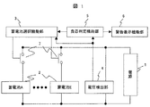
上記目的を達成するため、本発明によれば次のように構成される。図1に保管装置の構成概要図を示す。図1において、同一の部分が2つ以上あるものに関しては、同一の符号を付し、一部説明を省略する。電源1に対し、複数の蓄電池2が並列に配置され、該並列に接続された蓄電池2には各蓄電池に直列に充放電を切り替えるスイッチ7が接続されている。電源1には、複数の蓄電池2と電圧検出部4が並列に接続されている。蓄電池選択機能部3は、前記スイッチ7を用いて蓄電池を選択するため、蓄電池選択機能部3により選択された蓄電池の電圧が計測できる。
In order to achieve the above object, the present invention is configured as follows. FIG. 1 shows a schematic configuration diagram of the storage device. In FIG. 1, those having two or more identical parts are denoted by the same reference numerals, and a part of the description is omitted. A plurality of
良否判定機能部5は、電圧検出部4による電圧計測値とあらかじめ設定されている閾値電圧とを単独あるいは定期的に比較し、蓄電池2に対して充電の必要性と良否判定を実施し、充電が必要な場合は蓄電池2が所定の保存電圧値になるまで充電する。このとき、良否判定機能部5で不良の蓄電池を発見した場合には、警告表示機能部6へ警報表示の命令を出力する。蓄電池2への充電は、蓄電池選択機能部3から選択された蓄電池2に対しスイッチ7による切り換えにより行われる。
The pass / fail
蓄電池保管装置は、複数の、ホールCTやシャント抵抗型の電流センサ等を備え、各蓄電池の電流値を計測する電流計測手段(図示せず)と、並列に接続された蓄電池の電圧値を計測する電圧検出部4を有する。電圧検出部は独立したPT(Potential Transducer)あるいは分圧抵抗やオペアンプ,A/Dコンバータなどの電子部品で構成される。 The storage battery storage device includes a plurality of Hall CT and shunt resistance type current sensors and the like, and measures current values of each storage battery (not shown) and measures the voltage values of the storage batteries connected in parallel. The voltage detection part 4 which has. The voltage detection unit is composed of an independent PT (Potential Transducer) or an electronic component such as a voltage dividing resistor, an operational amplifier, or an A / D converter.
蓄電池保管装置は、電源1からの電流経路を形成するための正極および負極を接続する端子を有し、この端子は蓄電池と容易に接続可能な形状であり、端子結合部は絶縁被膜された形状が望ましい。また、前記スイッチ7には、突入電流を防止するために、充放電電源の電流容量および蓄電池の許容電流を考慮し、適切な値の抵抗を接続しても良い。電源1には、例えば複数の蓄電池2と並列に電圧検出部4が接続された構成となる。また、保管装置における電源1は少なくとも充電器を具備していればよく、必ずしも放電機能は具備していなくともよいため装置の小型化も可能である。
The storage battery storage device has a terminal for connecting a positive electrode and a negative electrode for forming a current path from the
図2を用いて良否判定機能部5について説明する。良否判定機能部5は、蓄電池の情報や操作命令を入力する操作部11,前記操作部11により入力された情報を演算する演算処理部13,演算処理部13の出力を記録するデータ記録部14,演算処理部13の演算結果及び操作状況を確認できる表示部12から構成される。
The quality
表示部12は蓄電池の状態等の表示をするものであり、各蓄電池の接続部にそれぞれ配置されていてもよい。演算処理部13は、蓄電池選択機能部3によりスイッチ7を選択投入し、選択した蓄電池2の電圧を電圧検出部4から受け取る。
The
演算処理部13による演算の結果、充電が必要であれば、蓄電池選択機能部により蓄電池と電源を接続し、蓄電池への充電を実施する。蓄電池は蓄電池選択機能部3により選択され、スイッチ7を投入された時のみ充放電が可能となるため、電源1の電源容量は、一つの蓄電池2の容量を1時間以内程度で充電可能とする容量を持っていれば良い。
If charging is necessary as a result of the calculation by the
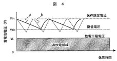
次に、図4を用いて蓄電池の電圧調整について説明する。良否判定機能部5は、電源1と蓄電池2との接続を蓄電池選択機能部3により順次変更し、測定された電圧が、電圧の閾値Vthの値を保管中に下回った場合に、充電が必要と判断して、選択された充電手段を保存設定電圧Vhまで充電する。
Next, the voltage adjustment of a storage battery is demonstrated using FIG. The pass / fail
蓄電池の保管時間において、上記充電を繰り返すと、蓄電池の電圧は図4のAと図4のBの様に電圧降下の期間が長い蓄電池と、電圧降下の期間が短い蓄電池が出てくる。閾値電圧Vthまでの電圧降下が長い蓄電池は良品であるが、ある傾き以上で電圧降下が起こる蓄電池は、蓄電池内部の電池内の微小短絡あるいは制御回路異常などの不良があると考えられる。そのため本実施例においては、保管されている期間中に閾値Vthを下回った回数もしくは電圧降下の速度をデータ記録部14に保存し、同期間における閾値Vthを下回った回数もしくは電圧降下の速度によりグレード分けを実施し、良品と不良品を判別し、蓄電池の電圧調整と共に不良品の選別を行う。詳細は後述する。
When the above charging is repeated during the storage time of the storage battery, a storage battery with a long voltage drop period and a storage battery with a short voltage drop period appear as shown in FIG. 4A and FIG. 4B. A storage battery with a long voltage drop to the threshold voltage Vth is a good product, but a storage battery in which a voltage drop occurs at a certain slope or more is considered to have a defect such as a minute short circuit in the battery inside the storage battery or an abnormal control circuit. For this reason, in this embodiment, the number of times that the threshold value Vth has been lowered or the voltage drop speed during the storage period is stored in the
本発明における保管時の動作を図5により説明する。まず、保管装置内の所定の蓄電池接続端子に蓄電池の端子を接続する。1つの蓄電池2を充電できる一組分の接続端子を1回線と定義し、保管装置は複数回線分の端子を有する。このとき、接続対象の回線のスイッチ7は開放されており、蓄電池と電源および他の電圧検出部等の回路は開回路状態つまり電気的に切り放された状態で接続される。ここで、端子は正負とも1箇所のコネクタで接続される形状でも、正負別々のコネクタで接続される形状であっても良い。また、好ましくは端子の露出がなく、作業者が容易に高電圧の触れることがない形状であることがない形状であることが望ましい(ステップ1)。
The operation at the time of storage in the present invention will be described with reference to FIG. First, a storage battery terminal is connected to a predetermined storage battery connection terminal in the storage device. One set of connection terminals that can charge one
次に、接続回線には識別番号が付され、接続された蓄電池2を対応する蓄電池選択するスイッチ7により選択できる構成となっている。次に保管装置の電源を投入し、システムを起動する(ステップ2)。ここで、システム起動の後に電池を接続する場合においては、接続している蓄電池に対して電源1が動作しないように、予め操作部11から蓄電池が接続されている回線のみで電源1が動作するように回線指定し入力を行う。蓄電池接続部にインタロックをかける方式と併設してもよい。
Next, an identification number is assigned to the connection line, and the connected
次に、蓄電池2の初期容量,蓄電池の残量と開回路電圧との関係,電池容量,最大電流値,接続蓄電池のロット番号や製造番号,入荷日,製造日等の蓄電池2の情報を操作部11から入力する(ステップ3)。なお、これらの情報は蓄電池に貼り付け或いは添付されたRFIDやバーコードなどの情報を直接専用のインターフェースで読み込んでも良い。
Next, the
次に、蓄電池の充放電に関する条件設定画面により、蓄電池の充電を開始する閾値電圧Vth,保存設定電圧Vh,充電上限電圧Vhh,過放電電圧VL,過充電保護電圧Vov,電圧確認間隔t等を操作部11から設定する。ここで、充電上限電圧Vhhは充電電流によるIRドロップ等を考慮して保存設定電圧Vh以上の値に設定するものとする。さらに、過充電警告電圧Vov,充電電流Ic,過電流Iov,充電最大時間tchなどの保護設定値も入力することで、より安全に充電できる(ステップ4)。
Next, the threshold voltage Vth, storage set voltage Vh, charge upper limit voltage Vhh, overdischarge voltage VL, overcharge protection voltage Vov, voltage check interval t, etc. for starting charging of the storage battery are displayed on the condition setting screen for charging and discharging the storage battery. Set from the
次に、保存開始命令を入力し電圧調整を実施する(ステップ5)。次に、電圧調整の実施結果をデータ記録部14に履歴記録し、良否判定機能部5により蓄電池の良否判定を行う(ステップ6)。次に、不良品と判定された蓄電池の各情報を警告表示機能部6へ出力する(ステップ7)。次に、次回の起動についての設定を行う(ステップ8)。2回目以降の保管の動作はステップ2からステップ8を繰り返す。但し、2回目のシステム起動からはステップ3およびステップ4を省略してステップ5を実施しても良い。蓄電池の保管期間の終わりと共に保管の動作を終了する。ステップ5〜ステップ8は詳細な動作を以下に述べる。
Next, a storage start command is input and voltage adjustment is performed (step 5). Next, a history of voltage adjustment results is recorded in the
図5のステップ5における電圧調整の動作を図6により詳細に示す。まず、保存開始の命令が入力される(S501)。次に、蓄電池選択機能部3によりスイッチ7を切り替えて、各蓄電池2が順番に選択され、全蓄電池2についての電圧が測定される(S502)。スイッチ7は電圧計測用と充電用と複数ある場合は電圧計測用のみ切り替えてもよい。
この時、蓄電池の電圧情報はすべてレポートとして時刻とともにデータ記録部に記録される。
FIG. 6 shows the voltage adjustment operation in
At this time, all the voltage information of the storage battery is recorded in the data recording unit together with the time as a report.
次に、取得した蓄電池の電圧Vを充電開始の閾値電圧Vthと比較する(S503)。V>Vthの場合は充電不要と判断する。V<Vthの場合は過放電電圧VLと比較し、V<VLの場合は不良蓄電池と判定し、充電は行わずに警告表示機能部6へ警告信号を出力する。一方、Vth≧V>VLとなった場合は、図5のステップ4であらかじめ入力されている条件データをもとに、充電時間や充電容量を算出する(S504)。
Next, the acquired voltage V of the storage battery is compared with the threshold voltage Vth at the start of charging (S503). When V> Vth, it is determined that charging is unnecessary. When V <Vth, it is compared with the overdischarge voltage VL, and when V <VL, it is determined as a defective storage battery, and a warning signal is output to the warning
次に、充電対象の蓄電池を選択し、充電用のスイッチ7を接続して充電を開始する(S505)。充電は充電終了直後の開回路時に蓄電池の内部抵抗による電圧降下の影響を抑える様に定電流定電圧充電もしくは低レート電流による定電流充電とすることが望ましい。充電終了後、開回路状態の蓄電池の電圧Vを保存設定電圧Vhと比較する(S506)。V≧Vhとならない場合再度ステップS503からS506で充電を実施し、V≧Vhとなった蓄電池は充電を終了する。ここで、スイッチ7による回路の切り換え時や充電中の各蓄電池2に流れる各電流値を計測する複数の電流検出部(図示せず)はホールCTやシャント抵抗型の電流センサ等からなるが、この電流検出部により過電流が検出された場合には速やかに充電をせずに回路を開放する。
Next, the storage battery to be charged is selected, and the charging
次に、他の蓄電池の中で閾値電圧Vthより電圧の低い蓄電池があるかどうかを調べる(S507)。他に閾値電圧Vthより電圧の低い蓄電池がある場合は、スイッチ7を切り換えて対象の蓄電池に電源を接続する(S508)。次に、対象の蓄電池に対応する充電時間や充電容量を算出し、その他の設定を読み込む(S509)。次にS505に戻り蓄電池を選択して充電を開始する。閾値より低い電圧の蓄電池がなくなるまで上述のステップを繰り返し、すべての充電対象となった蓄電池の電圧Vが、保存設定電圧Vhより高くなったとき、ステップ6へ移行する。
Next, it is examined whether there is a storage battery having a voltage lower than the threshold voltage Vth among other storage batteries (S507). If there is another storage battery having a voltage lower than the threshold voltage Vth, the
ステップ6ではステップ5において測定した各蓄電池の電圧計測値を、少なくとも充電前および充電後についてデータ記録部14に記録する(保管開始時を含む)。測定値は時刻の情報とともに記録され、蓄電池ごとに充電の回数が記録される。
In
また、ステップ5における電圧計測時に蓄電池の計測電圧Vが放電下限電圧VLよりも小さい場合には、その蓄電池を不良品と判定して充電は実施しない。さらに、データ記録部に記録された、電圧調整充電後の蓄電池2の電圧と、電圧調整充電前の電圧と、保管期間の情報を使用し、充電上限電圧設定値から充電開始前に測定した開回路の電圧の差分を保管時間で除して単位時間当たりの電圧降下の傾きα′を算出する。この電圧降下の傾きα′が正常蓄電池の場合の電圧降下の傾きαと比較して、許容値をはずれた大きな値であれば不良蓄電池と判定する。また、同一の保存期間において同一の製造時期・仕様における正常な蓄電池の充電回数の平均よりも充電回数が明らかに許容値より多い蓄電池については不良品と判定する。
Further, if the measured voltage V of the storage battery is smaller than the discharge lower limit voltage VL during voltage measurement in
ステップ7では、ステップ6で不良品と判定された蓄電池は警告表示機能部6に警告表示される。このときの警告はディスプレイ、またはパイロットランプ、またはブザー等の音で実施する。
In
次にステップ8では、データ記録部に記録された、電圧調整充電後の蓄電池2の電圧と、電圧調整充電前の電圧と、保管期間の情報を使用し、次回の起動設定を実施する。保存開始時の初回は、ステップ5で、充電を実施しない場合がほとんどであると考えられる。
この場合、あらかじめ正常な蓄電池が保存された場合の単位時間当たりの電圧低下の傾きαをステップ3或いはステップ4で入力しておき、保存開始時の蓄電池電圧Vから閾値電圧Vthを引いて傾きαで除して、閾値電圧Vthになるまでの時間を推算する。起動開始時刻はこの推定時間を経過後になるようにする。好ましくはこの閾値のSOCが1〜2%低下するまでの時間経過後が望ましい。2回目以降はデータ記録部に記録された、電圧調整充電後の蓄電池2の電圧と、電圧調整充電前の電圧と、保管期間の情報を使用し、充電上限電圧設定値から充電開始前に測定した開回路の電圧の差分を保管時間で除して電圧降下の傾きα′を算出する。さらに、現在の蓄電池の電圧Vと閾値電圧Vthの電圧差を傾きα′で除し、次に充電が必要になる時期を算出する。全蓄電池に対して上述の計算を行い、次に充電が必要になる日時が最も早いものを、次回起動開始日時として設定する。次回起動設定は、全蓄電池一斉としても良いし、蓄電池をグループ分けし、グループごとに設定しても良い。
Next, in step 8, the next start-up setting is performed using the information of the
In this case, the slope α of the voltage drop per unit time when a normal storage battery is stored in advance is input in
求めた次回起動開始日時は、保管装置の内部もしくは外付けのタイマー等で保管期間を記憶しており、次回起動開始日時を経過したときに、自動で保管装置の電源および電圧検出部を起動させる。保管装置のこのような自動起動は、対象の蓄電池が出荷あるいは不良により取り外されるまで実行する。出荷または不良により取り外される場合は、操作部11からの入力によって、良否判定機能部5に保管終了の情報を入力し、新たに蓄電池接続結線があるまで自動充放電の対象外とする。
The next startup start date and time obtained is stored in the storage device with an internal or external timer, etc., and when the next startup start date and time elapses, the storage device power supply and voltage detector are automatically started. . Such automatic activation of the storage device is executed until the target storage battery is removed due to shipment or failure. In the case of removal due to shipment or failure, information on the end of storage is input to the pass / fail
以上のように、蓄電池保管時の充放電を実施する。保存設定電圧Vhと充電開始の閾値電圧Vthの幅を適切に取ることで、各蓄電池の充電時間を調節できる。そのため例えば、閾値電圧VthをSOC0%時の電圧とし、保存設定電圧Vhを満充電のSOC100%時電圧とした場合でも1C電流値での充電時間は1時間程で充電可能である。実運用上はVthもVhもこの範囲内であるので、より短時間で電圧調整することが可能である。充電時間が一時間で完了するように設定した場合には、1台の電源によって24台の蓄電池2を1日で充電完了することも可能となる。
As described above, charging / discharging during storage of the storage battery is performed. By appropriately taking the width of the storage setting voltage Vh and the threshold voltage Vth for starting charging, the charging time of each storage battery can be adjusted. Therefore, for example, even when the threshold voltage Vth is set to the voltage at
複数の蓄電池から電池システムを組み上げる場合において、直列接続で電圧が高いシステムでは蓄電池の容量の配分バラツキが小さくなるよう、また並列接続で容量の大きいシステムでは蓄電池の接続間で大電流の横流による発熱等による不具合が発生しないよう、蓄電池の電圧をある規定値の範囲内で揃えて接続することが必要である。 When assembling a battery system from multiple storage batteries, the distribution of the storage battery capacity is reduced in a system with a high voltage in series connection, and in a system with a large capacity in a parallel connection, heat is generated due to a large current cross current between the storage battery connections. Therefore, it is necessary to connect the storage battery voltages so that the voltages of the storage batteries are aligned within a specified range.
そこで、本発明の保管装置は、これまでの充電回数の履歴,電圧降下の傾きの履歴等をデータ記録部に記録し、演算処理部13にて蓄電池の品質が同等レベルの蓄電池を選別し、表示部12に表示する機能を備える。この品質レベル選別機能により、蓄電池の品質バラツキを縮小することが可能となり、品質が同等レベルと選別された蓄電池群で電池システムを構成することで電池システムの信頼性が向上する。さらに、品質が同等レベルと選別された複数の蓄電池2の電圧をより高精度に均質化するために、出荷時に微量の放電あるいは充電を実施することにより蓄電池の電圧を微調整する。その後、電圧微調整後の履歴をデータ記録部に残し、選別された蓄電池を保管装置より切り離す。切り離された複数の蓄電池で電池システムを構成する。
Therefore, the storage device of the present invention records the history of the number of times of charging so far, the history of the slope of the voltage drop, etc. in the data recording unit, and selects the storage battery with the same level of storage battery quality in the
図7に蓄電池を出荷する際の電圧微調整の一例を示す。始めに出荷モードを起動する(ステップN1)。蓄電池保管時にデータ記録部14に記録した既存のデータを読み込み(ステップN2)、必要な蓄電池の数および電圧のばらつき許容値等の選択条件を設定する(ステップN3)。データ記録部14に記録されたデータを参照して設定した条件を満たす適切な蓄電池2を選択する。選択された蓄電池2を表示部12に表示する。ここで、出荷組み付け時の基準電圧Vbを設定する。Vbは手動で操作部11から入力しても良いし、あらかじめ保管時に入力済みのものを呼び出しても良い(ステップN4)。
FIG. 7 shows an example of voltage fine adjustment when shipping the storage battery. First, the shipping mode is activated (step N1). Existing data recorded in the
次に、選択された蓄電池2に対し、蓄電池選択機能部3およびスイッチ7により順次接続を切り替えて電圧検出部4にて電圧を測定する(ステップN5)。充電あるいは放電の設定をする(ステップN6)。選択された各蓄電池2を充/放電し、基準電圧Vbに蓄電池2の電圧Vを揃える(ステップN7)。蓄電池2の電圧Vが基準電圧Vbと等しいかどうか比較を行う。ここで、電圧ばらつきの許容差が、任意に設定される蓄電池容量の数%以内に納まっているときは、蓄電池2の電圧Vが基準電圧Vbと等しいものとする(ステップN8)。
Next, the selected
ステップN8の条件を満たしていないものはステップN4からステップN8を繰り返し、ステップN8の条件を満たしたときに、選択された蓄電池2のみを互いに接続する(ステップN9)。選択された各蓄電池2が並列接続されるときは電源1からは電気的に切断されている。選択された蓄電池間を並列に接続すると横流により電圧が一致する。このときの電流値と電圧値を所定期間記録し、電流と電圧の変化の傾きが零に近い値、例えば1mV/秒など任意の値となったときに、最終の蓄電池の電圧として表示する。
Those that do not satisfy the condition of Step N8 repeat Steps N4 to N8, and when the condition of Step N8 is satisfied, only the selected
また、ステップN9で接続された各蓄電池は選択接続されたことが分かるように表示がなされる。例えば、表示部12に接続された蓄電池の識別番号等を表示しても良いし、蓄電池に設置された発光素子やランプの点灯により、色で識別できる方式でも良い。接続された蓄電池は保管装置から順次開回路とし、保存終了の命令を入力して履歴をデータ記録部14に保存し、蓄電池の保管を終了し、蓄電池を出荷する。このとき、電圧履歴を蓄電池に記録できる機能を有しているものについては書き込みを実施し、蓄電池に備えてもよい。
Further, a display is made so that it can be seen that each storage battery connected in step N9 is selectively connected. For example, an identification number or the like of the storage battery connected to the
蓄電池の内部抵抗が不揃いの場合や、蓄電池が微小短絡や回路不良等によって使用不可になった場合などは蓄電池を交換することになる。本発明を適用した場合は蓄電池の自己放電による過放電を防ぐことができ、かつ、保管期間中に微小短絡や内部抵抗の高いものを容易に選別することが可能となるため、蓄電池の性能を品質別に選別し、大規模な電池システムの信頼性を向上させることが可能となる。 When the internal resistance of the storage battery is uneven or when the storage battery becomes unusable due to a minute short circuit or a circuit failure, the storage battery is replaced. When the present invention is applied, it is possible to prevent overdischarge due to self-discharge of the storage battery, and it is possible to easily select a short-circuit or a high internal resistance during the storage period. By sorting by quality, it becomes possible to improve the reliability of a large-scale battery system.
また、従来は電池システムに組み込む前に各蓄電池の充放電を個別に実施するために必要であった時間と手順を短縮し、かつ、電源の装置規模も小さくすることが可能となった。さらには、電池システムの製造工程において、蓄電池を接続するために電圧を揃える工程を自動で実施するため、電池システムの接続工程が短縮できる。蓄電池の履歴についても管理がなされるため、保守もしやすくなる。 In addition, it has become possible to shorten the time and procedure conventionally required to individually charge and discharge each storage battery before incorporating it into the battery system, and to reduce the device scale of the power supply. Furthermore, in the manufacturing process of the battery system, the process of aligning the voltages to connect the storage batteries is automatically performed, so the connection process of the battery system can be shortened. Since the storage battery history is also managed, maintenance is facilitated.
本実施例では、充電は充電終了直後の開回路時に蓄電池の内部抵抗による電圧降下の影響を抑える様に、定電流定電圧充電もしくは低レート電流による定電流充電とするとしたが、短時間で電圧を基準保存電圧付近に回復するために、保存基準電圧以上の電圧まで定電流で充電するか、保存基準電圧まで定格電流以上の定電流定電圧充電を実施しても良い。 In this embodiment, charging is performed with constant current / constant voltage charging or constant current charging with a low rate current so as to suppress the influence of voltage drop due to the internal resistance of the storage battery in the open circuit immediately after the end of charging. In order to recover the voltage near the reference storage voltage, the battery may be charged with a constant current up to a voltage equal to or higher than the storage reference voltage, or may be charged with a constant current and constant voltage higher than the rated current up to the storage reference voltage.
次にリチウムイオン電池に適用した一例を示す。単電池の電池使用範囲が上限4.1V,下限2.7Vで平均電圧3.6Vの電池をX個直列にした定格電圧3.6XV、定格容量B Ahの蓄電池を保管する。該蓄電池には、蓄電池内の単電池の各電圧を上位制御回路に通信できる制御回路を内蔵し、信号出力端子を電源接続用端子と別に具備している。 Next, an example applied to a lithium ion battery is shown. A storage battery with a rated voltage of 3.6 XV and a rated capacity B Ah in which X batteries with an average voltage of 3.6 V with an upper limit of 4.1 V and a lower limit of 2.7 V and an average voltage of 3.6 V are stored. The storage battery has a built-in control circuit capable of communicating each voltage of the single cell in the storage battery to the host control circuit, and has a signal output terminal separately from the power connection terminal.
保管装置には、充放電用の接続端子の他に、各単電池電圧を上位に通信する端子の出力を受ける端子も具備する。実施例1のステップ6で電圧判定する際に、単電池電圧も同時に取得することにより、各単電池についても各電圧と電圧降下の傾きを算出することが可能となる。筐体内部での直列数Xが大きい高電圧の蓄電池においては、複数単電池のうち、不良電池が混入していても電圧の影響が小さく見え、不良を発見できない場合があるが、各単電池電圧を取得できるために、著しく特性の異なる単電池が直列接続内に混入していることをシステム組み込み前に発見し、不良として取り出すことで未然にシステムの不具合を防ぐことが可能になる。蓄電池の不良が発生した場合に、筐体内のどの単電池が不良になっているかで、制御回路や、単電池そのものの不具合原因の推定が容易になる利点がある。
In addition to the charging / discharging connection terminals, the storage device also includes a terminal that receives an output of a terminal that communicates each cell voltage to the upper level. When the voltage is determined in
さらに、通信により、蓄電池に例えば内蔵された制御回路等にデータ保存領域がある場合、履歴を保存し、保守時に活用する。 Further, when there is a data storage area in a control circuit or the like built in the storage battery by communication, the history is stored and used during maintenance.
リチウムイオン電池では高エネルギー密度であるため、蓄電池の複数直並列接続時は、安全上、万一短絡した場合でも放電エネルギーが小さくなるように低SOC,望ましくはSOC50%〜SOC0%の範囲の状態で保管するのが望ましい。たとえば、充電開始の閾値電圧はSOC20%時の電圧とし、保管電圧をSOC50%時の電圧とする。システムに組み込む場合に、選択された蓄電池2は、取り外し時に所望の電圧が得られるように、出荷モードの図7のステップN6で必要な複数の蓄電池2を決定した後、要求電圧と電圧差が大きい場合は各蓄電池を順次選択して放電または充電して電圧調整した後に、選択全電池を並列接続する図7のステップN7により電圧を均等化する。
Since lithium ion batteries have a high energy density, when connecting multiple storage batteries in series and parallel, for safety reasons, the SOC is low so that the discharge energy is reduced even if a short circuit occurs, preferably in the range of SOC 50% to
また、保存設定電圧Vhはリチウムイオン電池の正極活物質,負極活物質,電解液などの構成材料の種類により特性が異なるため、保存時の劣化影響が小さくなる電圧を電池仕様にあわせて選択するとより蓄電池を有効に使用することができる。 In addition, since the storage setting voltage Vh has different characteristics depending on the types of constituent materials such as the positive electrode active material, the negative electrode active material, and the electrolyte solution of the lithium ion battery, a voltage that reduces the deterioration effect during storage is selected according to the battery specifications The storage battery can be used more effectively.
蓄電池がニッケル水素電池の場合の保管時電圧調整の一例を示す。満充電時の充電終止時は計測電圧が一旦上昇してから低下する。そのため、電圧変化の傾きを検知して充電終止とするΔV制御が出来る構成が望ましい。保管装置における充放電部1の充電終止の制御のために、充電時の電圧変化を記録し、満充電は電圧が一旦上昇してから低下するΔV検知が出来る構成としても良い。熱電対やサーミスタなどの熱検知素子を追加した構成で、これらの情報を良否判定に利用することもできる。
An example of the voltage adjustment at the time of storage in case a storage battery is a nickel metal hydride battery is shown. At the end of charging when fully charged, the measured voltage rises once and then drops. For this reason, a configuration capable of performing ΔV control for detecting the slope of the voltage change and terminating charging is desirable. In order to control the end of charging of the charging / discharging
ここで、図1に示した保管装置の構成概要図とは異なる他の保管装置の構成概要図を、図8に示す。図1に示す構成と同一の部分は同一の符号を付し、一部説明を省略する。図8で示す保管装置の構成は、上述の各実施例に適応できるのである。電源1に対し、複数の蓄電池2が並列に配置され、該並列に接続された蓄電池2には各蓄電池に直列に充放電を切り替えるスイッチ7が接続されている。電源1には、複数の蓄電池2と電圧検出部4が並列に接続されている。また、電圧検出部4に直列に電圧計測選択スイッチ7′が接続されている。蓄電池選択機能部3は、前記電圧計測選択スイッチ7′を用いて蓄電池を選択するため、蓄電池選択機能部3により選択された蓄電池の電圧が計測できる。良否判定機能部5は、電圧検出部4による電圧計測値とあらかじめ設定されている閾値電圧とを単独あるいは定期的に比較し、蓄電池2に対して充電の必要性と良否判定を実施し、充電が必要な場合は電源出力開放スイッチ8を閉じて蓄電池2が所定の保存電圧値になるまで充電する。このとき、良否判定機能部5で不良の蓄電池を発見した場合には、警告表示機能部6へ警報表示の命令を出力する。蓄電池2への充電は、蓄電池選択機能部3から選択された蓄電池2に対しスイッチ7による切り換えにより行われる。
Here, FIG. 8 shows a schematic configuration diagram of another storage device different from the schematic configuration diagram of the storage device shown in FIG. The same parts as those shown in FIG. 1 are denoted by the same reference numerals, and a part of the description is omitted. The configuration of the storage device shown in FIG. 8 can be applied to the above-described embodiments. A plurality of
上述のそれぞれの実施例においては、単電池を複数直列化して組電池としたユニット、或いはこれをさらに複数接続した構成で、外観上、単一のブロック状、或いは筐体に収容された形状で、一組の正極端子,負極端子で電流入出力経路を有するモジュールを蓄電池と定義したが、蓄電池を単電池と置き換えてもそれぞれの実施例は適応可能である。 In each of the above-described embodiments, a plurality of unit cells are connected in series to form an assembled battery, or a configuration in which a plurality of units are connected, and in appearance, in a single block shape or a shape accommodated in a housing. Although a module having a current input / output path with a pair of positive electrode terminal and negative electrode terminal is defined as a storage battery, each embodiment can be applied even if the storage battery is replaced with a single battery.
本発明における蓄電池はリチウム二次電池に限らず、ニッケル水素電池,NAS電池,鉛電池,電気二重層キャパシタなどの充放電可能な蓄電素子を多並列多直列に接続した電池システムすべてに適用可能である。特にOVまで完全に放電した場合に過放電による転極、不可逆反応による機能失活が問題となる二次電池系や電気二重層キャパシタなどは、本発明の導入効果が顕著となる。これらの電池システムを使用できるハイブリッド自動車,電気自動車,電動バイク,電動バス・トラック,鉄道車両,建設機械,地上給電設備,変電所、などあらゆる電池システムの大規模電池システムの安定維持について有効である。 The storage battery according to the present invention is not limited to a lithium secondary battery, and can be applied to all battery systems in which chargeable / dischargeable storage elements such as nickel metal hydride batteries, NAS batteries, lead batteries, and electric double layer capacitors are connected in multiple parallel and multiple series. is there. In particular, the secondary battery system and the electric double layer capacitor in which inversion due to overdischarge and functional deactivation due to irreversible reaction are problematic when completely discharged to OV have a remarkable effect of introducing the present invention. Effective for the stable maintenance of large-scale battery systems such as hybrid vehicles, electric vehicles, electric motorcycles, electric buses and trucks, railway vehicles, construction machinery, ground power supply facilities, substations, etc. that can use these battery systems .
大規模システム中の蓄電池の内部抵抗が不ぞろいの場合、特に単電池が微小短絡等により、使用不可になった場合などは蓄電池を交換せざるを得ずシステム寿命が想定値よりも短縮される不具合が起こる。本発明を適用した場合、高価な蓄電池の自己放電に起因する過放電による機能失活を防止することができ、かつ、保管中に微小短絡などの不良が起きている蓄電池を容易に選別することができるため、蓄電池の性能をグレード別に選別し、使用することで大規模蓄電池システムの信頼性を向上させることが可能になる。 If the internal resistance of the storage battery in a large-scale system is uneven, especially if the battery becomes unusable due to a short circuit, etc., the storage battery must be replaced and the system life is shortened from the expected value. Happens. When the present invention is applied, it is possible to prevent functional deactivation due to overdischarge resulting from self-discharge of an expensive storage battery, and to easily select a storage battery in which a defect such as a micro short circuit occurs during storage. Therefore, it is possible to improve the reliability of a large-scale storage battery system by selecting and using the storage battery performance by grade.
また、これまで、組み込み前に各蓄電池の充放電が個別に実施するために必要であった時間と手順を短縮、且つ蓄電池を電圧調整するための充放電電源の装置規模も小さくすることが可能となる。 In addition, it has been possible to shorten the time and procedure required to charge and discharge each storage battery before installation, and to reduce the scale of the charge / discharge power supply for adjusting the voltage of the storage battery. It becomes.
さらには工程内での煩雑さが解消され、蓄電池接続のために電圧を揃える工程を、自動で実施するため、組電池システムの接続工程が短縮できる。蓄電池の履歴についても管理がなされるため、保守もしやすくなるという利点がある。 Furthermore, since the complexity in the process is eliminated and the process of aligning the voltages for connecting the storage battery is automatically performed, the connection process of the assembled battery system can be shortened. Since the history of the storage battery is also managed, there is an advantage that maintenance is easy.
1 電源
2 蓄電池
3 蓄電池選択機能部
4 電圧検出部
5 良否判定機能部
6 警告表示機能部
7 スイッチ
7′ 電圧計測選択スイッチ
8 電源出力開放スイッチ
11 操作部
12 表示部
13 演算処理部
14 データ記録部
DESCRIPTION OF
Claims (16)
前記蓄電池を充放電させる電源と、
前記蓄電池の電圧を検出する電圧検出部と、
前記電圧計測手段の検出電圧を記録するデータ記録部と、
前記データ記録部に記録された電圧情報から前記蓄電池の品質の良否を判定する良否判定機能部と、を有し、
前記電源から電池に通電しない状態において、前記蓄電池の電圧降下の傾きと、現在の蓄電池の電圧と、前記蓄電池の補充電実施の基準の第一の閾値電圧と、により次回補充電開始までの所定時間間隔を求め、
前記電圧検出部による前記蓄電池の電圧検出、及び検出電圧が前記第一の閾値電圧を下回った場合に実施する前記電源による第二の閾値電圧である所定電圧までの前記蓄電池の充放電、及び前記データ記録部に基づいた前記蓄電池の良否判定、を行う保管動作を前記所定時間間隔で繰り返し実施することを特徴とする蓄電池保管装置。 A storage battery storage device that can be connected to a plurality of chargeable / dischargeable storage batteries and stores the plurality of storage batteries,
A power source for charging and discharging the storage battery;
A voltage detector for detecting the voltage of the storage battery;
A data recording unit for recording the detected voltage of the voltage measuring means;
Have a, a quality determining function unit determines the quality of the quality of the battery from the voltage information recorded in the data recording unit,
In a state in which the battery is not energized from the power source, a predetermined time until the start of the next auxiliary charging is determined by the slope of the voltage drop of the storage battery, the current storage battery voltage, and the first threshold voltage of the reference for performing the auxiliary charging of the storage battery. Find the time interval,
Voltage detection of the storage battery by the voltage detection unit, charging / discharging of the storage battery up to a predetermined voltage that is a second threshold voltage by the power source, which is performed when the detection voltage falls below the first threshold voltage, and A storage battery storage device that repeatedly performs a storage operation for performing pass / fail judgment of the storage battery based on a data recording unit at the predetermined time interval .
前記蓄電池の良否判定は、
前記蓄電池の検出電圧が放電下限値電圧である第三の閾値電圧よりも小さい場合に不良品と判定する手段、
及び、前記データ記録部で記録された前記蓄電池の検出電圧により、蓄電池の検出電圧が前記第一の閾値電圧を下回った単位時間における回数が許容値よりも多い場合に不良品と判定する手段、
及び、前記データ記録部で記録された前記蓄電池の検出電圧により、単位時間当たりの電圧降下の傾きにより良否の判定をする手段、を有することを特徴とする蓄電池保管装置。 The storage battery storage device of claim 1,
The quality determination of the storage battery is as follows:
Means for determining a defective product when the detection voltage of the storage battery is lower than a third threshold voltage which is a discharge lower limit voltage;
And means for determining that the detected voltage of the storage battery recorded by the data recording unit is a defective product when the number of times the unit battery detection voltage is lower than the first threshold voltage is greater than a permissible value,
A storage battery storage device comprising: means for determining pass / fail based on a slope of a voltage drop per unit time based on the detected voltage of the storage battery recorded by the data recording unit.
前記良否判定機能部は、前記蓄電池の検出電圧の降下速度が所定値よりも速いときに、前記蓄電池を不良品と判定することを特徴とする蓄電池保管装置。 The storage battery storage device of claim 1,
The quality determination function unit determines that the storage battery is defective when the rate of decrease in the detection voltage of the storage battery is faster than a predetermined value.
前記蓄電池保管装置は、前記蓄電池の検出電圧が前記第一の閾値電圧よりも小さいときに前記電源により前記蓄電池を充電する手段を備え、
前記良否判定機能部は、前記蓄電池の単位時間における充電回数に応じて、前記蓄電池の良否を判定することを特徴とする蓄電池保管装置。 The storage battery storage device of claim 1,
The storage battery storage device includes means for charging the storage battery with the power supply when a detection voltage of the storage battery is lower than the first threshold voltage ,
The storage battery storage device, wherein the pass / fail determination function unit determines pass / fail of the storage battery according to the number of times the storage battery is charged per unit time .
前記蓄電池保管装置は、前記良否判定機能部が前記蓄電池を不良品と判定した場合に、
該蓄電池を警告表示する警告表示機能部を有することを特徴とする蓄電池保管装置。 The storage battery storage device of claim 1,
The storage battery storage device, when the quality determination function unit determines that the storage battery is a defective product,
A storage battery storage device comprising a warning display function unit for displaying a warning of the storage battery.
前記複数の蓄電池から任意の蓄電池を1乃至複数選択し、選択した前記蓄電池を前記電源と電気的に接続する蓄電池選択機能部を有し、
前記蓄電池保管装置は、検出電圧の降下速度がほぼ等しい前記蓄電池を任意の数で選択し電気的に接続する手段を有することを特徴とする蓄電池保管装置。 The storage battery storage device of claim 1,
One or more arbitrary storage batteries are selected from the plurality of storage batteries, and a storage battery selection function unit that electrically connects the selected storage batteries to the power source is provided.
The storage battery storage device has means for selecting and electrically connecting any number of the storage batteries having substantially equal detection voltage drop rates.
前記蓄電池保管装置は、充電回数がほぼ等しい前記蓄電池を電気的に接続する手段を有することを特徴とする蓄電池保管装置。 The storage battery storage device of claim 6,
The storage battery storage device has means for electrically connecting the storage batteries having approximately the same number of times of charging.
前記蓄電池の電圧を検出し、
検出した電圧値に応じて前記蓄電池を充電し、
前記蓄電池の電圧値の履歴を記録し、
前記履歴に応じて前記蓄電池の品質の良否を判定し、
前記蓄電池の電圧降下の傾きと、現在の蓄電池の電圧と、前記蓄電池の充電開始の判断のための第一の閾値電圧と、により所定時間間隔を求め、
前記蓄電池の電圧検出、及び検出した電圧値に応じた前記蓄電池の充電、及び前記蓄電池の電圧値の履歴記録、及び前記履歴に応じた前記蓄電池の品質良否判断、を行う保管動作を前記所定時間間隔で繰り返し実施することを特徴とする蓄電池保管方法。 A storage battery storage method for storing a plurality of storage batteries,
Detecting the voltage of the storage battery,
Charging the storage battery according to the detected voltage value,
Record the voltage value history of the storage battery,
The quality of the storage battery is determined according to the history ,
The predetermined time interval is determined by the slope of the voltage drop of the storage battery, the current storage battery voltage, and the first threshold voltage for determining the start of charging of the storage battery,
A storage operation for detecting the voltage of the storage battery, charging the storage battery according to the detected voltage value, recording a history of the voltage value of the storage battery, and determining whether the storage battery is good or bad according to the history is the predetermined time. A storage battery storage method, which is repeatedly performed at intervals .
前記履歴から算出される電圧降下速度および電圧がほぼ等しい複数の前記蓄電池を電気的に接続することを特徴とする蓄電池保管方法。A storage battery storage method comprising electrically connecting a plurality of storage batteries having substantially the same voltage drop speed and voltage calculated from the history.
前記蓄電池を充放電させる電源と、
前記蓄電池の電圧を検出する電圧検出部と、
前記電圧検出部の電圧検出値が所定値より低いときに、前記複数の蓄電池から充放電させる特定の蓄電池を選択する蓄電池選択機能部と、
前記電圧検出部の検出電圧の履歴に基づいて前記蓄電池の品質を判定する品質判定手段と、を有し、
前記蓄電池の電圧降下の傾きと、現在の蓄電池の電圧と、前記蓄電池の充電可否の判断のための前記所定値の電圧と、により所定時間間隔を求め、
前記電圧検出部による前記蓄電池の電圧検出、及び検出電圧が前記所定値より低いときに実施する前記蓄電池の充放電、及び検出電圧の履歴に基づいた前記蓄電池の良否判定、を行う保管動作を前記所定時間間隔で繰り返し実施することを特徴とする蓄電池保管装置。 A storage battery storage device connected to a plurality of storage batteries and storing the plurality of storage batteries,
A power source for charging and discharging the storage battery;
A voltage detector for detecting the voltage of the storage battery;
A storage battery selection function unit that selects a specific storage battery to be charged / discharged from the plurality of storage batteries when a voltage detection value of the voltage detection unit is lower than a predetermined value;
Quality judgment means for judging the quality of the storage battery based on the history of the detection voltage of the voltage detection unit,
A predetermined time interval is determined by the slope of the voltage drop of the storage battery, the current storage battery voltage, and the voltage of the predetermined value for determining whether the storage battery can be charged,
Storage operation for performing voltage detection of the storage battery by the voltage detection unit, charging / discharging of the storage battery performed when the detection voltage is lower than the predetermined value, and quality determination of the storage battery based on a history of detection voltage A storage battery storage device, which is repeatedly performed at predetermined time intervals .
前記電圧検出部の検出電圧の履歴から算出される電圧の降下速度が所定値よりも速いときに、前記品質判定手段は、前記蓄電池を不良品と判定することを特徴とする蓄電池保管装置。The storage battery storage device, wherein the quality determination unit determines that the storage battery is defective when a voltage drop rate calculated from a history of detection voltages of the voltage detection unit is faster than a predetermined value.
前記蓄電池保管装置は、前記品質判定手段が前記蓄電池を不良品と判定した場合に、警告を表示する警告表示機能部を有することを特徴とする蓄電池保管装置。The storage battery storage device includes a warning display function unit that displays a warning when the quality determination unit determines that the storage battery is defective.
前記蓄電池保管装置は、前記電圧の降下速度および前記検出電圧がほぼ等しい前記蓄電池を電気的に接続する手段を有することを特徴とする蓄電池保管装置。The storage battery storage device has means for electrically connecting the storage batteries having substantially the same voltage drop rate and the detected voltage.
前記蓄電池は、単電池を複数直列して組電池としたユニット、または当該ユニットをさらに複数接続して構成されることを特徴とする蓄電池保管方法。The storage battery is a storage battery storage method characterized in that a plurality of unit cells are connected in series to form an assembled battery, or a plurality of such units are connected.
Priority Applications (1)
| Application Number | Priority Date | Filing Date | Title |
|---|---|---|---|
| JP2007250392A JP5033562B2 (en) | 2007-09-27 | 2007-09-27 | Storage battery storage device and storage battery storage method |
Applications Claiming Priority (1)
| Application Number | Priority Date | Filing Date | Title |
|---|---|---|---|
| JP2007250392A JP5033562B2 (en) | 2007-09-27 | 2007-09-27 | Storage battery storage device and storage battery storage method |
Publications (2)
| Publication Number | Publication Date |
|---|---|
| JP2009081078A JP2009081078A (en) | 2009-04-16 |
| JP5033562B2 true JP5033562B2 (en) | 2012-09-26 |
Family
ID=40655664
Family Applications (1)
| Application Number | Title | Priority Date | Filing Date |
|---|---|---|---|
| JP2007250392A Expired - Fee Related JP5033562B2 (en) | 2007-09-27 | 2007-09-27 | Storage battery storage device and storage battery storage method |
Country Status (1)
| Country | Link |
|---|---|
| JP (1) | JP5033562B2 (en) |
Families Citing this family (13)
| Publication number | Priority date | Publication date | Assignee | Title |
|---|---|---|---|---|
| JP5412245B2 (en) | 2009-11-09 | 2014-02-12 | 株式会社日立製作所 | Diagnostic system and diagnostic method for lithium ion secondary battery |
| JP2011113759A (en) * | 2009-11-25 | 2011-06-09 | Diamond Electric Mfg Co Ltd | Device and method for battery management |
| JP5444190B2 (en) * | 2010-11-01 | 2014-03-19 | Necアクセステクニカ株式会社 | Battery control system, battery control method, and battery control program |
| JP5896599B2 (en) * | 2010-12-28 | 2016-03-30 | 株式会社豊田自動織機 | Vehicle charging device and vehicle charging method |
| WO2012117498A1 (en) * | 2011-02-28 | 2012-09-07 | 株式会社日立製作所 | Battery module composition determining system and battery module composition determining method |
| EP2717424B1 (en) * | 2011-05-31 | 2018-02-21 | LG Chem, Ltd. | Apparatus for leveling voltage for connecting unit racks for storing power, and system for storing power comprising same |
| JP5682708B2 (en) * | 2011-06-03 | 2015-03-11 | トヨタ自動車株式会社 | Power storage system |
| JP5859341B2 (en) * | 2012-02-28 | 2016-02-10 | 三菱重工業株式会社 | Voltage equalizing apparatus and method, program, and power storage system including the same |
| CN103376351A (en) * | 2012-04-11 | 2013-10-30 | 雅马哈发动机株式会社 | Low-voltage warning method and apparatus for vehicle secondary cell |
| KR101778348B1 (en) * | 2014-10-24 | 2017-09-13 | 주식회사 엘지화학 | System capacity measure of secondary battery and method for measuring capacity of secondary battery |
| CN104362400B (en) * | 2014-11-17 | 2016-08-17 | 国网河南省电力公司南阳供电公司 | A kind of online sulphur removal maintenance process of storage batteries of transformer substation based on LAN and system |
| CN108365277A (en) * | 2018-01-12 | 2018-08-03 | 威马智慧出行科技(上海)有限公司 | Copper bar connective stability monitoring method, apparatus and system in electrokinetic cell system |
| JP6881356B2 (en) * | 2018-03-08 | 2021-06-02 | 東芝三菱電機産業システム株式会社 | Battery system |
Family Cites Families (7)
| Publication number | Priority date | Publication date | Assignee | Title |
|---|---|---|---|---|
| ZA782491B (en) * | 1978-05-01 | 1979-12-27 | Anglo Amer Corp South Africa | Battery testing |
| JP3157369B2 (en) * | 1993-10-29 | 2001-04-16 | 三洋電機株式会社 | Protection method and protection device for secondary battery |
| JPH09163620A (en) * | 1995-12-05 | 1997-06-20 | Suzuki Motor Corp | Charger |
| JPH10319101A (en) * | 1997-05-20 | 1998-12-04 | Nec Corp | Device and method for detecting degree of deterioration of battery |
| JP2002231318A (en) * | 2001-02-06 | 2002-08-16 | Sanyo Electric Co Ltd | Storing method for nickel hydrogen storage battery |
| JP2002359009A (en) * | 2001-05-31 | 2002-12-13 | Sanyo Electric Co Ltd | Charger |
| JP3706376B2 (en) * | 2003-07-29 | 2005-10-12 | 武次 西田 | Degradation battery evaluation test equipment |
-
2007
- 2007-09-27 JP JP2007250392A patent/JP5033562B2/en not_active Expired - Fee Related
Also Published As
| Publication number | Publication date |
|---|---|
| JP2009081078A (en) | 2009-04-16 |
Similar Documents
| Publication | Publication Date | Title |
|---|---|---|
| JP5033562B2 (en) | Storage battery storage device and storage battery storage method | |
| US10298011B2 (en) | Electric storage apparatus and power path switch apparatus | |
| US10707686B2 (en) | Battery management | |
| JP4533329B2 (en) | Semiconductor integrated circuit for charge control and charging device using the semiconductor integrated circuit for charge control | |
| WO2014132403A1 (en) | Device for assessing extent of degradation in secondary cell | |
| CN102754272A (en) | Apparatus and method for managing a battery pack | |
| CN104521093A (en) | Battery charging and maintaining with defective battery monitoring | |
| KR20170062765A (en) | Apparatus method for defect detecting of the battery cell by unknown discharge current | |
| CN105510831A (en) | Method for monitoring state of battery in motor vehicle | |
| CN113795964A (en) | Battery diagnosis apparatus and method | |
| JP2023101507A (en) | Control device and control method for lithium-ion secondary battery | |
| EP2713174A1 (en) | Method and apparatus for diagnosing faults in a battery pack, and power relay assembly using same | |
| KR102437323B1 (en) | Apparatus for diagnosing battery pack | |
| JP2001006750A (en) | Battery inspecting device | |
| US11885852B2 (en) | Battery management device, energy storage apparatus, battery management method, and computer program | |
| JP2023535441A (en) | Battery resistance calculator and method | |
| JP2003045387A (en) | Battery pack system, and deterioration decision method of the same | |
| JP5230789B2 (en) | Battery system | |
| JP2003217686A (en) | Method for grasping status of battery | |
| CN103501028A (en) | Lithium power battery black box device and achieving method thereof | |
| CN115461958A (en) | Battery management system, battery pack, energy storage system and battery management method | |
| JP6977779B2 (en) | Management device, power storage device, cause analysis method, engine-driven vehicle, electric vehicle | |
| JP2012028049A (en) | Method of manufacturing power storage device, and power storage device | |
| JP6365725B2 (en) | Power storage device and power path switching device | |
| KR20210145024A (en) | Method for detecting defective battery cells and battery management system providing the same |
Legal Events
| Date | Code | Title | Description |
|---|---|---|---|
| A621 | Written request for application examination |
Free format text: JAPANESE INTERMEDIATE CODE: A621 Effective date: 20090330 |
|
| A977 | Report on retrieval |
Free format text: JAPANESE INTERMEDIATE CODE: A971007 Effective date: 20110630 |
|
| A131 | Notification of reasons for refusal |
Free format text: JAPANESE INTERMEDIATE CODE: A131 Effective date: 20110719 |
|
| A521 | Written amendment |
Free format text: JAPANESE INTERMEDIATE CODE: A523 Effective date: 20110920 |
|
| TRDD | Decision of grant or rejection written | ||
| A01 | Written decision to grant a patent or to grant a registration (utility model) |
Free format text: JAPANESE INTERMEDIATE CODE: A01 Effective date: 20120605 |
|
| A01 | Written decision to grant a patent or to grant a registration (utility model) |
Free format text: JAPANESE INTERMEDIATE CODE: A01 |
|
| A61 | First payment of annual fees (during grant procedure) |
Free format text: JAPANESE INTERMEDIATE CODE: A61 Effective date: 20120702 |
|
| FPAY | Renewal fee payment (event date is renewal date of database) |
Free format text: PAYMENT UNTIL: 20150706 Year of fee payment: 3 |
|
| LAPS | Cancellation because of no payment of annual fees |