JP5032344B2 - Image decoding apparatus and image decoding method - Google Patents
Image decoding apparatus and image decoding method Download PDFInfo
- Publication number
- JP5032344B2 JP5032344B2 JP2007557749A JP2007557749A JP5032344B2 JP 5032344 B2 JP5032344 B2 JP 5032344B2 JP 2007557749 A JP2007557749 A JP 2007557749A JP 2007557749 A JP2007557749 A JP 2007557749A JP 5032344 B2 JP5032344 B2 JP 5032344B2
- Authority
- JP
- Japan
- Prior art keywords
- unit
- decoding
- error
- region
- error compensation
- Prior art date
- Legal status (The legal status is an assumption and is not a legal conclusion. Google has not performed a legal analysis and makes no representation as to the accuracy of the status listed.)
- Expired - Fee Related
Links
Images


Classifications
-
- H—ELECTRICITY
- H04—ELECTRIC COMMUNICATION TECHNIQUE
- H04N—PICTORIAL COMMUNICATION, e.g. TELEVISION
- H04N19/00—Methods or arrangements for coding, decoding, compressing or decompressing digital video signals
- H04N19/10—Methods or arrangements for coding, decoding, compressing or decompressing digital video signals using adaptive coding
- H04N19/169—Methods or arrangements for coding, decoding, compressing or decompressing digital video signals using adaptive coding characterised by the coding unit, i.e. the structural portion or semantic portion of the video signal being the object or the subject of the adaptive coding
- H04N19/17—Methods or arrangements for coding, decoding, compressing or decompressing digital video signals using adaptive coding characterised by the coding unit, i.e. the structural portion or semantic portion of the video signal being the object or the subject of the adaptive coding the unit being an image region, e.g. an object
- H04N19/174—Methods or arrangements for coding, decoding, compressing or decompressing digital video signals using adaptive coding characterised by the coding unit, i.e. the structural portion or semantic portion of the video signal being the object or the subject of the adaptive coding the unit being an image region, e.g. an object the region being a slice, e.g. a line of blocks or a group of blocks
-
- H—ELECTRICITY
- H04—ELECTRIC COMMUNICATION TECHNIQUE
- H04N—PICTORIAL COMMUNICATION, e.g. TELEVISION
- H04N19/00—Methods or arrangements for coding, decoding, compressing or decompressing digital video signals
- H04N19/50—Methods or arrangements for coding, decoding, compressing or decompressing digital video signals using predictive coding
- H04N19/503—Methods or arrangements for coding, decoding, compressing or decompressing digital video signals using predictive coding involving temporal prediction
- H04N19/51—Motion estimation or motion compensation
- H04N19/527—Global motion vector estimation
-
- H—ELECTRICITY
- H04—ELECTRIC COMMUNICATION TECHNIQUE
- H04N—PICTORIAL COMMUNICATION, e.g. TELEVISION
- H04N19/00—Methods or arrangements for coding, decoding, compressing or decompressing digital video signals
- H04N19/60—Methods or arrangements for coding, decoding, compressing or decompressing digital video signals using transform coding
- H04N19/61—Methods or arrangements for coding, decoding, compressing or decompressing digital video signals using transform coding in combination with predictive coding
-
- H—ELECTRICITY
- H04—ELECTRIC COMMUNICATION TECHNIQUE
- H04N—PICTORIAL COMMUNICATION, e.g. TELEVISION
- H04N19/00—Methods or arrangements for coding, decoding, compressing or decompressing digital video signals
- H04N19/80—Details of filtering operations specially adapted for video compression, e.g. for pixel interpolation
- H04N19/82—Details of filtering operations specially adapted for video compression, e.g. for pixel interpolation involving filtering within a prediction loop
-
- H—ELECTRICITY
- H04—ELECTRIC COMMUNICATION TECHNIQUE
- H04N—PICTORIAL COMMUNICATION, e.g. TELEVISION
- H04N19/00—Methods or arrangements for coding, decoding, compressing or decompressing digital video signals
- H04N19/85—Methods or arrangements for coding, decoding, compressing or decompressing digital video signals using pre-processing or post-processing specially adapted for video compression
- H04N19/89—Methods or arrangements for coding, decoding, compressing or decompressing digital video signals using pre-processing or post-processing specially adapted for video compression involving methods or arrangements for detection of transmission errors at the decoder
- H04N19/895—Methods or arrangements for coding, decoding, compressing or decompressing digital video signals using pre-processing or post-processing specially adapted for video compression involving methods or arrangements for detection of transmission errors at the decoder in combination with error concealment
Landscapes
- Engineering & Computer Science (AREA)
- Multimedia (AREA)
- Signal Processing (AREA)
- Compression Or Coding Systems Of Tv Signals (AREA)
Description
本発明は、圧縮された画像データの復号において復号エラーが発生した場合に、適切にエラー補償を行う画像復号装置および画像復号方法に関するものである。 The present invention relates to an image decoding apparatus and an image decoding method that appropriately perform error compensation when a decoding error occurs in decoding of compressed image data.
動画像の符号化方式として、MPEG2やMPEG4が用いられている。現在では、MPEG4よりさらに圧縮効率を向上させた「H.264/MPEG4 AVC」(以下、「H.264」という)が、Joint Video Team(以下、「JVT」という)により規格化されている。 MPEG2 or MPEG4 is used as a moving image encoding method. At present, “H.264 / MPEG4 AVC” (hereinafter referred to as “H.264”), which is further improved in compression efficiency compared with MPEG4, is standardized by Joint Video Team (hereinafter referred to as “JVT”).
図13は、MPEG4により規格化されている画像復号装置のブロック図である。 FIG. 13 is a block diagram of an image decoding apparatus standardized by MPEG4.
可変長復号部100は、可変長符号化されたデータストリームを、可変長符号化テーブルに従って復号する。逆ACDC予測部101は、ACDC予測を行い、量子化係数QF[x][y]を出力する。逆量子化部102は、量子化係数QF[x][y]に対して逆量子化を行うことでDCT係数F[x][y]を出力する。逆DCT部103は、DCT係数F[x][y]に対して逆DCTを行う。イントラマクロブロック符号化により符号化されたマクロブロック(以下、「イントラマクロブロック」と言う)の復号時には、デコード画像の画素値が得られ、インターマクロブロック符号化により符号化されたマクロブロック(以下、「インターマクロブロック」という)の復号時には、前画像との差分画素値が得られる。動き補償部104は、差分画素値を用いて、データ画像の画素を得る。
The variable
図14は、H.264により規格化されている画像復号装置のブロック図である。 FIG. 1 is a block diagram of an image decoding apparatus standardized by H.264.
H.264に基づく画像復号装置は、MPEG4に基づく画像復号装置と異なり、ループ内フィルタ112を備えている。ループ内フィルタ112は、復号後の画素値に対して符号化単位のブロック境界に対して、デブロックフィルタ処理を行う。デブロックフィルタ処理により、表示される画像のブロックノイズが低減するメリットがある。
H. Unlike an image decoding apparatus based on MPEG4, an image decoding apparatus based on H.264 includes an in-
H.264におけるデブロックフィルタ処理について説明する。図15は、デブロックフィルタ処理において取り扱われる画素の例示図である。図中のブロック境界を挟んだ画素を用いて、フィルタ処理が行われる。図中において、マトリクスの各々は画素を示しており、画素のそれぞれに画素を区別する符号が付されている。 H. A deblocking filter process in H.264 will be described. FIG. 15 is a diagram illustrating pixels handled in the deblocking filter process. Filter processing is performed using pixels sandwiching the block boundary in the figure. In the figure, each matrix represents a pixel, and each pixel is given a symbol for distinguishing the pixel.
まず、デブロックフィルタ処理の実行、非実行は、(数1)により判断される。 First, execution or non-execution of the deblocking filter process is determined by (Equation 1).

ここで、(数1)の左辺は、デブロックフィルタの実行の有無を示すフラグであり、H.264において、規定されている。右辺の変数「bS」は、デブロックフィルタ処理における平滑化の度合いを示すパラメータであり、値「0」から値「4」の整数の値を持つ。 Here, the left side of (Equation 1) is a flag indicating whether or not the deblocking filter is executed. H.264. The variable “bS” on the right side is a parameter indicating the degree of smoothing in the deblocking filter process, and has an integer value from “0” to “4”.
変数「bS」が、値「0」の場合には、ループ内フィルタ110は、デブロックフィルタ処理を行わない。変数「bS」が値「1」、値「2」、値「3」の何れかの場合には、(数2)に従いデブロックフィルタ処理が行われる。変数「bS」が値「4」の場合には、(数3)に従い、デブロックフィルタ処理が行われる。
When the variable “bS” is the value “0”, the in-
(数1)から(数3)に含まれる変数「p0」などのそれぞれは、図15中の画素を特定する「p0」などのそれぞれに対応する画素の画素値である。 Each of the variables “p0” and the like included in (Equation 1) to (Equation 3) is a pixel value of a pixel corresponding to each of “p0” and the like specifying the pixel in FIG.
以上のように、復号対象となる単位領域を越えた画素を用いて、デブロックフィルタ処理が行われる。すなわち、ある単位領域と隣接する単位領域の画素が用いられて、ある単位領域の画素のデブロックフィルタ処理が行われる。 As described above, the deblocking filter process is performed using pixels that exceed the unit area to be decoded. That is, a pixel in a unit region adjacent to a certain unit region is used, and a deblocking filter process is performed on the pixel in a certain unit region.
ここで、H.264(及びMPEG4)においては、可変長復号部100が、可変長符号化テーブルを参照し、一致するビット列を検出することで、データストリームを復号する。
Here, H. In H.264 (and MPEG4), the variable
このとき、復号対象のデータストリーム中に、可変長符号化テーブルに含まれるビット列パターンのいずれにも相当しない場合がある。この場合は、復号エラーと判断される。このような復号エラーが発生した場合には、復号対象の単位領域(例えばスライスなど)の全てが復号エラーの発生した領域として取り扱われる。このように復号エラーが発生した場合には、次の単位領域から改めて可変長復号が再開され、復号エラーの発生した単位領域の画素値は使用されない。 At this time, the data stream to be decoded may not correspond to any of the bit string patterns included in the variable length coding table. In this case, it is determined as a decoding error. When such a decoding error occurs, all the unit areas (for example, slices) to be decoded are handled as areas where a decoding error has occurred. When a decoding error occurs in this way, variable length decoding is restarted from the next unit area, and the pixel value of the unit area where the decoding error has occurred is not used.
ここで、復号エラーの発生している単位領域の画素値が不使用となるので、不使用となった単位領域を放置すると表示画像が乱れることになる。 Here, since the pixel value of the unit area where the decoding error has occurred is not used, the display image is disturbed if the unused unit area is left unattended.
この表示画像の乱れを防止するため、復号エラーの発生した単位領域に含まれる画素の値が、時間的に過去のフレームに含まれる画素の値で置き換えられる技術が提案されている(例えば、特許文献1参照)。あるいは、復号エラーの発生した単位領域に含まれる画素の値が、同一フレーム内の他の単位領域に含まれる画素の値で置き換えられる技術が提案されている(例えば特許文献2参照)。 In order to prevent the display image from being disturbed, a technique has been proposed in which the value of a pixel included in a unit area where a decoding error has occurred is replaced with the value of a pixel included in a temporally past frame (for example, a patent). Reference 1). Alternatively, a technique has been proposed in which the value of a pixel included in a unit area where a decoding error has occurred is replaced with the value of a pixel included in another unit area in the same frame (see, for example, Patent Document 2).
しかしながら、従来の技術では、復号エラーの発生した単位領域に含まれる画素の値のみが、他の画素の値により置き換えられるだけである。ここで、ループ内フィルタ110によりデブロックフィルタ処理が行われるため、復号エラーの発生した単位領域の境界に位置する画素は、隣接する単位領域のデブロックフィルタ処理に用いられる。すなわち、隣接する単位領域のデブロックフィルタ処理において、復号エラーの発生した画素が用いられることになる。このため、復号エラーの発生している単位領域だけでなく、復号エラーの発生している単位領域に含まれる画素を用いてデブロックフィルタ処理が施される隣接する単位領域の画素も乱れることになる。つまり、復号エラーが発生している単位領域に隣接する単位領域は、復号エラーに起因する影響を受ける。
However, in the conventional technique, only the value of a pixel included in a unit area where a decoding error has occurred is simply replaced with the value of another pixel. Here, since the deblocking filter process is performed by the in-
復号エラーの発生している単位領域に含まれる画素の値は、他の画素の値により置き換えられるが、復号エラーに起因する影響を受けている隣接する画素はそのままである。このため、従来技術は、この隣接する画素の画質に悪影響が残ったままであり、表示画像が劣化する問題を有していた。 The value of the pixel included in the unit area where the decoding error has occurred is replaced by the value of another pixel, but the adjacent pixels that are affected by the decoding error remain as they are. For this reason, the conventional technique has a problem that the image quality of the adjacent pixels remains adversely affected and the display image is deteriorated.
例えば、図16に示されるように、復号エラーが発生している単位領域に隣接する単位領域の画素は、復号エラーに起因する影響を残したままである。 For example, as illustrated in FIG. 16, the pixel in the unit area adjacent to the unit area where the decoding error has occurred remains affected by the decoding error.
図16は、従来の技術における復号エラーの発生による影響を示す説明図である。 FIG. 16 is an explanatory diagram showing the influence of the occurrence of a decoding error in the conventional technique.
復号エラーの発生した単位領域に含まれる画素(図中の円であって、×印が付されているもの)において、枠で囲まれた画素が、隣接する単位領域におけるデブロックフィルタ処理に用いられる。このため、復号エラー発生のない単位領域においても、デブロックフィルタ処理時に悪影響を受けてしまう(図中の円であって、△印が付されているもの)。復号エラーの発生した単位領域に含まれる画素の値が、他の画素の値により置き換えられた場合(図中の右側)であっても、△印の付されている画素はそのままであり、表示画像に乱れが残る。
そこで本発明は、復号エラーの発生した単位領域に加えて、フィルタ処理によりこの復号エラーに起因する影響を受ける画素も含めたエラー処理を行うことのできる画像復号装置および画像復号方法を提供することを目的とする。 Accordingly, the present invention provides an image decoding apparatus and an image decoding method capable of performing error processing including a pixel affected by a decoding error in addition to a unit region where a decoding error has occurred, by a filtering process. With the goal.
第1の発明に係る画像復号装置は、1フレームの画像中に含まれる単位領域毎の復号エラーを検出するエラー検出部と、復号エラーに対するエラー補償を行うエラー補償領域を決定するエラー補償領域決定部と、エラー補償領域に対してエラー補償を行うエラー補償部を備え、エラー補償領域決定部は、復号エラーの発生している単位領域と、単位領域に隣接する所定領域を、エラー補償領域として決定する。 An image decoding apparatus according to a first aspect of the present invention includes an error detection unit that detects a decoding error for each unit area included in an image of one frame, and an error compensation region determination that determines an error compensation region for performing error compensation for the decoding error. And an error compensation unit that performs error compensation on the error compensation region, and the error compensation region determination unit uses a unit region where a decoding error has occurred and a predetermined region adjacent to the unit region as an error compensation region. decide.
この構成により、復号エラーの発生している単位領域のみならず、復号エラーの発生している単位領域の影響を受ける周辺も含めて、エラー補償が行われる。 With this configuration, error compensation is performed not only for the unit area where the decoding error occurs but also for the periphery affected by the unit area where the decoding error occurs.
第2の発明に係る画像復号装置では、第1の発明に加えて、所定領域は、復号エラーの発生している単位領域に含まれる画素を用いたループ内フィルタ処理の対象となる画素を含む領域である。 In the image decoding apparatus according to the second invention, in addition to the first invention, the predetermined area includes a pixel that is a target of an in-loop filter process using a pixel included in a unit area in which a decoding error occurs. It is an area.
この構成により、復号エラーの生じた単位領域の画素による影響を受ける周辺の画素も、エラー補償の対象となる。特に、デブロックフィルタのような、単位領域を越えた画素を用いたフィルタ処理を含む画像処理では、有効である。 With this configuration, surrounding pixels that are affected by the pixel in the unit area where the decoding error has occurred are also subject to error compensation. In particular, it is effective in image processing including filter processing using pixels exceeding a unit area, such as a deblocking filter.
第3の発明に係る画像復号装置では、第1の発明に加えて、単位領域は、H.263規格、もしくはH.264規格で規定されているスライスおよびマクロブロックのいずれかを構成単位とする。 In the image decoding device according to the third aspect of the present invention, in addition to the first aspect, the unit area is an H.264 format. H.263 standard or H.264 One of the slices and macroblocks defined in the H.264 standard is used as a structural unit.
第4の発明に係る画像復号装置では、第3の発明に加えて、単位領域は、受信状態に応じて、スライスおよびマクロブロックのいずれかを、構成単位とする。 In the image decoding device according to the fourth invention, in addition to the third invention, the unit area has either a slice or a macroblock as a constituent unit according to the reception state.
これら構成により、復号エラーの発生頻度にあわせて、エラー補償に必要となる演算量の調整ができる。 With these configurations, the amount of calculation required for error compensation can be adjusted in accordance with the frequency of occurrence of decoding errors.
第5の発明に係る画像復号装置では、第1の発明に加えて、復号エラーは、算術復号エラー及び可変長復号エラーの少なくとも一方を含む。 In the image decoding device according to the fifth invention, in addition to the first invention, the decoding error includes at least one of an arithmetic decoding error and a variable length decoding error.
この構成により、復号エラーが容易に検出できる。 With this configuration, a decoding error can be easily detected.
第6の発明に係る画像復号装置では、第2の発明に加えて、ループ内フィルタ処理の実行状態と非実行状態を判定する判定部を更に備え、判定部の判定結果において、ループ内フィルタ処理が実行状態である場合に、エラー補償領域決定部は、復号エラーの発生している単位領域に含まれる画素を用いたループ内フィルタ処理の対象となる画素を含む領域を、所定領域として決定する。 In addition to the second invention, the image decoding device according to the sixth aspect of the present invention further includes a determination unit that determines an execution state and a non-execution state of the in-loop filter processing, and in the determination result of the determination unit, the in-loop filter processing Is in the execution state, the error compensation region determination unit determines, as a predetermined region, a region including a pixel to be subjected to an in-loop filter process using a pixel included in a unit region where a decoding error has occurred. .
この構成により、所定領域に含まれる画素は、復号エラーの発生した単位領域に含まれる画素の影響を受ける場合だけ、エラー補償される。この結果、エラー補償に要する負荷が、効率よく低減できる。 With this configuration, the pixels included in the predetermined area are error-compensated only when affected by the pixels included in the unit area where the decoding error has occurred. As a result, the load required for error compensation can be efficiently reduced.
第7の発明に係る画像復号装置では、第2の発明に加えて、エラー補償領域決定部は、ループ内フィルタによるフィルタ領域の変化に合わせて、所定領域を変化させる。 In the image decoding device according to the seventh invention, in addition to the second invention, the error compensation region determination unit changes the predetermined region in accordance with the change of the filter region by the in-loop filter.
この構成により、効率よく、エラー補償が行われる。 With this configuration, error compensation is performed efficiently.
第8の発明に係る画像復号装置では、第1の発明に加えて、エラー補償部は、エラー補償領域に含まれる画素の値を、時間的に過去のフレームに含まれる対応する画素の値で置き換える。 In the image decoding device according to the eighth aspect of the invention, in addition to the first aspect, the error compensation unit converts the value of the pixel included in the error compensation area to the value of the corresponding pixel included in the temporally past frame. replace.
この構成により、容易にエラー補償が行われ、加えて表示画像の乱れも非常に小さくできる。 With this configuration, error compensation is easily performed, and in addition, the disturbance of the display image can be extremely reduced.
第9の発明に係る画像復号装置では、第1の発明に加えて、エラー補償部は、エラー補償領域に含まれる画素の値を、エラー補償領域の近傍の画素の値で置き換える。 In the image decoding device according to the ninth invention, in addition to the first invention, the error compensation unit replaces the value of the pixel included in the error compensation region with the value of a pixel in the vicinity of the error compensation region.
この構成により、簡易にエラー補償が行われる。また、エラー補償のために必要となるメモリ容量も少なくてすむ。 With this configuration, error compensation is easily performed. Also, less memory capacity is required for error compensation.
第10の発明に係る画像復号装置では、第1の発明に加えて、エラー補償部は、エラー補償領域に含まれる画素の値を、固定値で置き換える。 In the image decoding device according to the tenth invention, in addition to the first invention, the error compensation unit replaces the value of the pixel included in the error compensation region with a fixed value.
この構成により、簡易な構成で、エラー補償が行われる。 With this configuration, error compensation is performed with a simple configuration.
第11の発明に係る画像復号装置では、第1の発明に加えて、エラー補償部は、エラー補償領域の内、所定領域に含まれる画素の値を、所定領域に含まれる対応する画素であってループ内フィルタ処理前の画素の値で置き換える。 In the image decoding device according to the eleventh invention, in addition to the first invention, the error compensation unit is configured to change a value of a pixel included in the predetermined area of the error compensation area to a corresponding pixel included in the predetermined area. Replace with the value of the pixel before filter processing in the loop.
この構成により、復号エラーの発生している画素を用いたループ内フィルタ処理による悪影響を排除できる。 With this configuration, it is possible to eliminate an adverse effect caused by the in-loop filter process using a pixel in which a decoding error has occurred.
本発明によれば、画像フレーム中であって復号エラーの発生した単位領域(復号を行う単位)のみならず、この復号エラーに起因する影響を受ける他の単位領域に含まれる画素についても、エラー補償が行われる。この結果、単位領域境界でのフィルタ処理が行われる画像復号において復号エラーが生じる場合であっても、表示画像の画質劣化が抑制される。 According to the present invention, not only a unit area (decoding unit) in a picture frame in which a decoding error has occurred, but also errors in pixels included in other unit areas affected by the decoding error. Compensation is performed. As a result, even when a decoding error occurs in image decoding in which filter processing at the unit region boundary is performed, image quality deterioration of the display image is suppressed.
また、フィルタ処理の実行の判定に基づいてエラー補償を行うエラー補償領域が決定されることで、効率的なエラー補償ができる。また、エラー補償の不要な画素にはエラー補償が行われないので、表示画像の画質劣化が効果的に抑制される。 In addition, by determining an error compensation region in which error compensation is performed based on determination of execution of filter processing, efficient error compensation can be performed. Further, since error compensation is not performed on pixels that do not require error compensation, image quality degradation of the display image is effectively suppressed.
また、エラー補償として、エラー補償領域に含まれる画素の値が、過去のフレームの画素の値、同一フレームの他の位置の画素の値あるいは固定値で置き換えられることで、簡便且つ効果的に画質劣化が抑制される。 In addition, as error compensation, the pixel value included in the error compensation area is replaced with the value of a pixel in a past frame, the value of a pixel in another position in the same frame, or a fixed value, so that image quality can be simply and effectively. Deterioration is suppressed.
1 画像復号装置
2 可変長復号部
3 逆量子化部
4 逆DCT部
5 画素合成部
6 切り替え部
7 ループ内フィルタ
8 メモリ部
9 動き補償部
10 エラー検出部
11 エラー補償領域決定部
12 エラー補償部
13 算術復号部
DESCRIPTION OF
以下、図面を参照しながら、本発明の実施の形態を説明する。 Hereinafter, embodiments of the present invention will be described with reference to the drawings.
(実施の形態1)
図1、図2は、本発明の実施の形態1における画像復号装置のブロック図である。
(Embodiment 1)
1 and 2 are block diagrams of the image decoding apparatus according to
(全体構成)
まず、画像復号装置1の構成について説明する。
(overall structure)
First, the configuration of the
画像復号装置1は、符号化されたデータストリームを復号する。
The
データストリームは、可変長復号部2に入力する。可変長復号部2は、入力したデータストリームを可変長復号する。具体的には、可変長復号部2は、入力したデータストリームに含まれるヘッダを解析し、更に可変長符号化テーブルを参照して、可変長符号化されているデータストリームを復号する。
The data stream is input to the variable
可変長復号部2は、まずデータストリームに含まれるスタートコードを検出し、スタートコードに続いて含まれるヘッダ情報から、種々のパラメータを復号する。このとき、可変長復号部2は、H.264やH.263などの規格で規定されているスライスに含まれるフィルタ処理フラグも検出する。可変長復号部2は、このフィルタ処理フラグを、ループ内フィルタ7に出力する。
The variable
同様に、可変長復号部2は、復号対象のマクロブロックがイントラマクロブロックであるか、インターマクロブロックであるかを検出し、検出結果をマクロブロック情報として切り替え部6に出力する。可変長復号部2は、動きベクトル情報を動き補償部9に出力し、可変長復号した結果を量子化データとして逆量子化部3に出力する。
Similarly, the variable
ここで、可変長復号部2は、1フレームの画像に含まれる、ある単位領域を一つの単位として復号を行う。例えば、単位領域は、H.263やH.264で規定されている「スライス」や「マクロブロック」を基準とする。
Here, the variable
ここで、H.263やH.264における復号では、「スライス」が復号の単位とされている。このため、単位領域は、この「スライス」を基準とするのが、復号処理との関係からも好適である。 Here, H. H.263 and H.264. In decoding in H.264, “slice” is a decoding unit. For this reason, it is preferable that the unit area is based on the “slice” from the viewpoint of the decoding process.
しかしながら、スライスの大きさは可変であり、場合によっては1フレーム全体が1スライスとして定義されることがある。このようにスライスの大きさが大きくなると、エラー補償を行う画素数が多くなり、演算量の増大をもたらす。エラー補償に要する演算量が増大することで、表示速度に追いつけなくなり表示が停止する事態も生じる。このように、エラー補償の演算量の増大による問題点が生じる場合には、単位領域は、「スライス」ではなく「マクロブロック」を基準としても良い。 However, the size of the slice is variable, and in some cases, one entire frame is defined as one slice. As the slice size increases, the number of pixels for error compensation increases, resulting in an increase in the amount of calculation. As the amount of calculation required for error compensation increases, there may be a situation where the display cannot be kept up with the display speed and the display stops. As described above, when a problem due to an increase in the amount of calculation for error compensation occurs, the unit area may be based on “macroblock” instead of “slice”.
例えば、受信状態が良い場合には、エラー補償の発生頻度は少ないので、単位領域は、「スライス」を基準とするのが好適である。これは、エラー補償にかかわる演算量の増大の問題が発生しにくいからである。一方、受信状態が悪い場合には、エラー補償の発生頻度が高くなるので、単位領域は、「マクロブロック」を基準とすることが好適である。これは、復号エラーを含まないマクロブロックをそのまま利用できるので、エラー補償にかかわる演算量を抑えることができるからである。 For example, when the reception state is good, since the frequency of occurrence of error compensation is low, the unit area is preferably based on “slice”. This is because the problem of increase in the amount of calculation related to error compensation is unlikely to occur. On the other hand, since the frequency of error compensation increases when the reception state is poor, it is preferable that the unit area is based on “macroblock”. This is because a macroblock that does not include a decoding error can be used as it is, so that the amount of calculation related to error compensation can be suppressed.
ここで、受信状態は、無線通信で受信された電波の受信レベルや受信波形に基づいたり、画像のストリームデータの誤り率に基づいたり、復号エラーの発生頻度や発生量に基づいたりして定義される。 Here, the reception state is defined based on the reception level and reception waveform of radio waves received by wireless communication, based on the error rate of image stream data, and based on the frequency and amount of decoding errors. The
受信状態を判定するブロックにより、単位領域の基準が、「スライス」であるか「マクロブロック」であるかが選択される。ここで、受信状態は、受信したデータストリームの電力や電圧レベルから判断されても良く、復号エラーの発生頻度から判断されても良い。 The block for determining the reception state selects whether the unit area reference is “slice” or “macroblock”. Here, the reception state may be determined from the power or voltage level of the received data stream, or may be determined from the frequency of occurrence of decoding errors.
あるいは、取り扱う「スライス」領域の大きさにより、単位領域が「スライス」を基準とするか、「マクロブロック」を基準とするかが選択されても良い。 Alternatively, whether the unit area is based on “slice” or “macroblock” may be selected depending on the size of the “slice” area to be handled.
なお、単位領域は、単一のスライスやマクロブロックを単位としても良いが、複数のスライスや複数のマクロブロックを単位としてもよい。 The unit area may be a single slice or macro block, but may be a plurality of slices or macro blocks.
図1では、画像復号装置1は、可変長復号部2を備えているが、図2にしめされるように、可変長復号部2の代わりに、算術復号部13を備えてもよい。
In FIG. 1, the
逆量子化部3は、可変長復号部2から出力された量子化データに対して逆量子化を行い、DCT係数を、逆DCT部4に出力する。
The
逆DCT部4は、逆量子化部3より出力されたDCT係数に対して、逆DCT処理を行い、復号画素値、もしくは差分画素値を出力する。
The
マクロブロック情報より、復号対象のマクロブロックがイントラマクロブロックの場合には、切り替え部6は、逆DCT部4から出力された復号画素値を選択して出力する。
If the decoding target macroblock is an intra macroblock based on the macroblock information, the
マクロブロック情報より、復号対象のマクロブロックがインターマクロブロックの場合には、切り替え部6は、画素合成部5より出力された復号画素値を選択して出力する。
When the macro block to be decoded is an inter macro block based on the macro block information, the
動き補償部9は、動きベクトル情報とメモリ部8に記憶されている参照画像から予測参照画素値を生成して、画素合成部5に出力する。動き補償部9は、H.264においては、輝度成分については1/4画素精度、色差成分については1/8画素精度で、予測参照画素値を生成する。なお、H.263においては、輝度成分は、1/2画素精度であり色差成分は、1/4画素精度である。
The
画素合成部5は、逆DCT部4より出力された差分画素値と、動き補償部9より出力された予測参照画素値を加算することで、復号画素値を生成する。画素合成部5で生成された復号画素値は、インターマクロブロックの場合には、切り替え部6で選択されて出力される。
The
ループ内フィルタ7は、フィルタ処理フラグに基づいて、ループ内フィルタ処理を行う。実施の形態1では、ループ内フィルタ処理の一例としてデブロックフィルタ処理に基づいた画像復号装置を説明する。
The in-
ループ内フィルタ7は、(数1)〜(数3)に基づいて、隣接する画素を用いて、デブロックフィルタ処理を行う。デブロックフィルタ処理では、スライスやマクロブロックなどの単位領域を越えた位置にある画素が用いられることがある。例えば、ある単位領域iに含まれる画素に対するデブロックフィルタ処理において、これに隣接する単位領域i+1に含まれる画素が用いられることがある。この場合には、復号を行う単位である単位領域をまたいで、デブロックフィルタ処理が行われる。
The in-
ループ内フィルタ7は、デブロックフィルタ処理を行った結果を、メモリ部8に出力する。メモリ部8は、ループ内フィルタ7の出力した結果を記憶しているので、表示画像として用いられる画像データを記憶していることになる。加えて、時間的に過去の表示画像の画像データも記憶しており、これは、動き補償部9での参照画像として用いられる。
The in-
ここで、可変長復号部2、逆量子化部3、逆DCT部4、動き補償部9は、符号化された画像データを復号する復号部を構成する要素である。復号部は、符号化された画像データに対する基本的な復号処理を行う。
Here, the variable
(エラー検出とエラー補償)
エラー検出部10は、可変長復号部2での復号において発生した復号エラーを検出する。可変長復号部2は、可変長符号化テーブルを参照して、可変長符号化テーブルに定義されたビット列と同じ並びのビット列を、データストリームから検出することで復号を行う(単位領域毎に復号する)。このとき、データストリームから、可変長符号化テーブルに定義されたいずれのビット列にも相当するビット列を検出できない場合には、エラー検出部10は、復号対象の単位領域を、復号エラーの発生した単位領域として判断する。
(Error detection and error compensation)
The
復号エラーが発生している単位領域に含まれる画素値は、以降は使用されない。復号エラーが検出された場合には、可変長復号部2は、次の単位領域のスタートコードを検出して、次の単位領域から改めて復号を行う。また、復号エラーが検出された場合には、後述のエラー補償が行われる。
Pixel values included in the unit area where a decoding error has occurred are not used thereafter. When a decoding error is detected, the variable
なお、画像復号装置1が、可変長復号部2の代わりに、算術復号部13を備えている場合には、算術復号エラーが発生した単位領域を、復号エラーが発生した単位領域として検出する。
When the
(エラー補償領域の決定)
エラー補償領域決定部11は、エラー検出部10での結果を受けて、エラー補償を行う対象であるエラー補償領域を決定する。
(Determination of error compensation area)
The error compensation
図3を用いて、エラー補償領域の決定について説明する。 The determination of the error compensation area will be described with reference to FIG.
図3は、本発明の実施の形態1におけるエラー補償領域の決定を説明する説明図である。 FIG. 3 is an explanatory diagram for explaining determination of the error compensation region in the first embodiment of the present invention.
図3における左側は、復号エラーが発生した場合の画素の状態を示している。単位領域iは、復号エラーの発生した単位領域であり、単位領域i−1は、復号エラーは発生していないが、復号エラーの発生した単位領域iと隣接する。ここで、単位領域i−1では、復号エラーは発生していない。しかし、単位領域i−1でのデブロックフィルタ処理は、復号エラーの発生している単位領域iに含まれる画素を用いる。この結果、復号エラーの発生していない単位領域i−1に含まれる画素の内、単位領域iに含まれる画素を用いてデブロックフィルタ処理(ループ内フィルタ7が行う)が行われる画素は、表示画像の画質劣化の原因となる。 The left side in FIG. 3 shows a pixel state when a decoding error occurs. The unit area i is a unit area in which a decoding error has occurred, and the unit area i-1 is adjacent to the unit area i in which a decoding error has occurred, although no decoding error has occurred. Here, no decoding error has occurred in the unit area i-1. However, the deblocking filter process in the unit area i-1 uses pixels included in the unit area i where a decoding error occurs. As a result, among the pixels included in the unit area i-1 in which no decoding error has occurred, the pixels subjected to the deblocking filter process (performed by the in-loop filter 7) using the pixels included in the unit area i are as follows: This causes deterioration of the image quality of the display image.
図3においては、○印は画素を示している。画素の内、△印が付されている画素は、復号エラーを起こしている単位領域iに含まれる画素を用いたデブロックフィルタ処理の影響を受けている。このため、復号エラーの発生している単位領域iのみがエラー補償領域として決定されても不十分である。 In FIG. 3, the ◯ marks indicate pixels. Among the pixels, pixels marked with Δ are affected by the deblocking filter process using the pixels included in the unit area i in which a decoding error has occurred. For this reason, it is not sufficient that only the unit area i in which a decoding error occurs is determined as the error compensation area.
図3の右半分には、エラー補償領域の決定の状態が示されている。 The right half of FIG. 3 shows the state of determining the error compensation area.
エラー補償領域決定部11は、復号エラーの発生している単位領域に加えて、この単位領域に隣接する所定領域を合わせて、エラー補償領域として決定する。図3においては、単位領域iに隣接した領域内の画素であって、単位領域iに含まれる画素をデブロックフィルタ処理において使用する画素を含む領域が、所定領域として決定される。
In addition to the unit area where the decoding error has occurred, the error compensation
エラー補償領域決定部11は、単位領域iと単位領域i−1の一部である所定領域を合わせた領域を、エラー補償領域として決定する。
The error compensation
なお、図3においては、単位領域i−1において単位領域iとの境界から縦方向に3画素までの領域が所定領域として決定されている。これは、デブロックフィルタ処理において、この縦方向に3画素までの画素が、単位領域iに含まれる画素を用いるからである。このため、単位領域i−1に含まれる画素であって、単位領域iに含まれる画素をデブロックフィルタ処理において用いる画素が、単位領域境界より縦方向に2画素の範囲に含まれる場合には、この2画素までの領域が所定領域として決定される。 In FIG. 3, in the unit region i-1, a region from the boundary with the unit region i to three pixels in the vertical direction is determined as the predetermined region. This is because in the deblocking filter processing, pixels up to three pixels in the vertical direction use pixels included in the unit region i. For this reason, when a pixel that is included in the unit area i-1 and that uses the pixel included in the unit area i in the deblocking filter processing is included in a range of two pixels in the vertical direction from the boundary of the unit area. The area up to two pixels is determined as the predetermined area.
なお、図3においては、フレーム中の上下方向を基準に単位領域境界がある場合について説明したが、横方向に単位領域境界がある場合であっても同様である。 In FIG. 3, the case where there is a unit region boundary with reference to the vertical direction in the frame has been described, but the same applies to the case where there is a unit region boundary in the horizontal direction.
また、エラー補償領域決定部11は、デブロックフィルタ処理の対象領域の変化に従って、エラー補償領域を変化させる。
Further, the error compensation
(エラー補償領域のバリエーション)
図4を用いて、エラー補償領域の決定の種々のバリエーションについて説明する。
(Variation of error compensation area)
Various variations in determining the error compensation area will be described with reference to FIG.
図4(a)〜図4(d)は、本発明の実施の形態1における、エラー補償領域の決定方法を説明する説明図である。 4 (a) to 4 (d) are explanatory diagrams for explaining a method for determining an error compensation region in the first embodiment of the present invention.
図4(a)〜図4(d)において、斜線が施されている領域は、エラー補償領域として決定される領域である。 In FIG. 4A to FIG. 4D, the hatched area is an area determined as an error compensation area.
図4(a)では、復号エラーの発生している単位領域iが、フレームの中の最上段に位置しており、単位領域iに含まれる画素をデブロックフィルタ処理で用いる、単位領域i以外に含まれる画素はない。このため、図4(a)では、単位領域iのみが、エラー補償領域として決定される。 In FIG. 4A, the unit area i in which a decoding error has occurred is located at the uppermost stage in the frame, and the pixels included in the unit area i are used in the deblocking filter processing except for the unit area i. There are no pixels included in. For this reason, in FIG. 4A, only the unit area i is determined as the error compensation area.
図4(b)においては、復号エラーの発生している単位領域iは、フレーム中の横方向において単位領域i−1と隣接している。単位領域i−1に含まれる画素の一部であって、単位領域iとの横方向における境界に近接する一定の領域の画素は、デブロックフィルタ処理において、単位領域iに含まれる画素を用いる。この一定の領域が、所定領域として決定される。結果として、単位領域iと、単位領域i−1の内で決定された所定領域がエラー補償領域として決定される。 In FIG. 4B, the unit area i in which a decoding error has occurred is adjacent to the unit area i-1 in the horizontal direction in the frame. The pixels included in the unit region i-1 and the pixels in a certain region close to the boundary in the horizontal direction with the unit region i use the pixels included in the unit region i in the deblocking filter process. . This certain area is determined as a predetermined area. As a result, the unit area i and a predetermined area determined in the unit area i-1 are determined as error compensation areas.
図4(c)においては、復号エラーの発生している単位領域iは、フレーム中の縦方向において単位領域i−1と隣接している。この単位領域i−1に含まれる画素の一部であって、単位領域iとの縦方向における境界に近接する一定の領域中の画素は、デブロックフィルタ処理において、単位領域iに含まれる画素を用いる。この一定の領域が、所定領域として決定される。結果として、単位領域iと、単位領域i−1の内の所定領域がエラー補償領域として決定される。 In FIG. 4C, the unit area i in which the decoding error has occurred is adjacent to the unit area i-1 in the vertical direction in the frame. A part of pixels included in the unit area i-1 and in a certain area close to the boundary in the vertical direction with the unit area i is a pixel included in the unit area i in the deblocking filter process. Is used. This certain area is determined as a predetermined area. As a result, the unit area i and a predetermined area in the unit area i-1 are determined as error compensation areas.
図4(d)においては、復号エラーの発生している単位領域iは、フレーム中の縦方向と横方向において単位領域i−1と隣接している。この単位領域i−1に含まれる画素の一部であって、単位領域iとの縦方向と横方向における境界に近接する一定の領域の画素に対するデブロックフィルタ処理は、単位領域iに含まれる画素を用いる。この一定の領域が、所定領域として決定される。結果として、単位領域iと、単位領域i−1の内の所定領域がエラー補償領域として決定される。 In FIG. 4D, the unit area i in which a decoding error has occurred is adjacent to the unit area i-1 in the vertical and horizontal directions in the frame. The deblocking filter processing for pixels in a certain region that is a part of the pixels included in the unit region i-1 and is close to the boundary in the vertical direction and the horizontal direction with the unit region i is included in the unit region i. Use pixels. This certain area is determined as a predetermined area. As a result, the unit area i and a predetermined area in the unit area i-1 are determined as error compensation areas.
なお、図4(a)〜図4(d)のいずれの場合も、所定領域は、デブロックフィルタ処理の対象領域に応じて変化する。エラー補償領域決定部11は、デブロックフィルタ処理の対象領域に基づいて、エラー補償領域を決定する。
Note that, in any of FIGS. 4A to 4D, the predetermined area changes according to the target area of the deblocking filter process. The error compensation
(エラー補償)
次に、エラー補償部12は、エラー補償領域に対して、エラー補償を行う。
(Error compensation)
Next, the
図5、図6を用いて説明する。図5、図6は、本発明の実施の形態1におけるエラー補償を説明する説明図である。 This will be described with reference to FIGS. 5 and 6 are explanatory diagrams for explaining error compensation in the first embodiment of the present invention.
(過去のフレームを用いたエラー補償)
次に、エラー補償の処理について説明する。
(Error compensation using past frames)
Next, error compensation processing will be described.
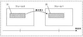
エラー補償部12は、図5に示されるように、エラー補償領域20に含まれる画素の値を、時間的に過去のフレームに含まれる対応する画素の値で置き換える。
As shown in FIG. 5, the
フレーム2は、フレーム1より時間的に過去のフレームである。フレーム1は、エラー補償領域20を含んでいる。エラー補償領域20に含まれる画素は、復号エラー、もしくは復号エラーに起因する影響を含んでいる。このため、エラー補償部12は、フレーム2の置き換え領域21に含まれる対応する画素の値によって、エラー補償領域20に含まれる画素の値を置き換える。
エラー補償領域20が複数の画素を含む場合、置き換え領域21に含まれると共にエラー補償領域20に含まれる各画素に対応する画素の値で、エラー補償領域20に含まれる画素の値が置き換えられる。
When the
置き換え領域21に含まれる画素は、フレーム1とは異なる時間での値を有しているが、時間的に非常に近いフレームであれば、相違は少ないため、置き換えても問題が少ない。結果として、復号エラーに起因する影響を残したままのフレーム1よりも、置き換えられたフレーム1の表示画像は、画質劣化が抑えられている。
The pixels included in the
なお、置き換え領域21は、フレーム2において、エラー補償領域20と同じ位置に存在する領域であることが、画質劣化抑制の点から好適である。しかし、エラー補償領域20の位置と近接する位置に存在する置き換え領域21が用いられても、画像状態によっては均等の効果は得られる。
Note that the
(近傍画素を用いたエラー補償)
あるいは、エラー補償部12は、エラー補償領域に含まれる画素の値を、図6に示されるように、同じフレームにおけるこのエラー補償領域20の近傍の置き換え領域22に含まれる画素の値で置き換える。
(Error compensation using neighboring pixels)
Alternatively, the
置き換え領域22は、エラー補償領域20に隣接する領域でも良く、離れた領域であっても良いが、画質劣化抑制の観点から、エラー補償領域20に隣接する領域であることが好適である。
The
(固定値を用いたエラー補償)
あるいは、エラー補償部12は、エラー補償領域に含まれる画素の値を、固定値で置き換える。固定値は、エラー補償領域全体で同じ値であってもよく、エラー補償領域内の位置によって異なる値であってもよい。
(Error compensation using fixed values)
Alternatively, the
以上の構成により、復号エラーの発生した単位領域に含まれる画素に加えて、この復号エラーの発生した単位領域の影響を受ける所定領域に含まれる画素(復号エラーの発生した単位領域に含まれる画素を用いてデブロックフィルタ処理を行う画素)も、エラー補償が行われる。結果として、復号エラーが発生した単位領域の境界における画質劣化を抑制できる。 With the above configuration, in addition to the pixels included in the unit area where the decoding error occurred, the pixels included in the predetermined area affected by the unit area where the decoding error occurred (the pixels included in the unit area where the decoding error occurred) The pixel that performs the deblocking filter processing using) is also subjected to error compensation. As a result, it is possible to suppress deterioration in image quality at the boundary between unit areas where a decoding error has occurred.
(フィルタ前の画素を用いたエラー補償)
また、エラー補償の対象であるエラー補償領域に含まれる所定領域は、復号エラーを発生していない領域であることもある。にもかかわらず、デブロックフィルタ処理において、復号エラーの発生している単位領域に含まれる画素が用いられるために、この所定領域はエラー補償が必要となるのである。すなわち、所定領域に関しては、デブロックフィルタ処理前の画素のままであれば、復号エラーに起因する悪影響はない。
(Error compensation using pre-filter pixels)
In addition, the predetermined area included in the error compensation area that is the object of error compensation may be an area where no decoding error has occurred. Nevertheless, in the deblocking filter process, since pixels included in the unit area where a decoding error occurs are used, error compensation is required for this predetermined area. In other words, as long as the predetermined area remains the pixel before the deblocking filter process, there is no adverse effect due to the decoding error.
このため、エラー補償部12は、エラー補償領域に含まれる所定領域の画素に対しては、所定領域に含まれる対応する画素であって、デブロックフィルタ処理前の画素の値で置き換える。加えて、エラー補償領域に含まれる所定領域以外の画素に対しては、上述の通り、前のフレームの画素の値による置き換えや固定値による置き換えなどを行う。
For this reason, the
ここで、デブロックフィルタ処理前の画素の値として、メモリに記憶されているデブロックフィルタ処理が実行される前の画素の値が用いられる。あるいは、デブロックフィルタ処理がなされた画素の値に対して、フィルタ処理の演算と逆演算が施されることで、デブロックフィルタ処理前の画素の値が算出される。デブロックフィルタ処理の逆演算がなされることで、デブロックフィルタ処理前の画素の値を記憶する必要がない。 Here, the value of the pixel before the deblocking filter process stored in the memory is used as the pixel value before the deblocking filter process. Alternatively, the value of the pixel before the deblocking filter process is calculated by performing the inverse operation and the calculation of the filtering process on the pixel value that has been subjected to the deblocking filter process. Since the inverse operation of the deblocking filter process is performed, it is not necessary to store the pixel value before the deblocking filter process.
このようなエラー補償により、所定領域については、デブロックフィルタ処理前の状態に戻せるので、復号エラーに起因する影響が排除される。所定領域以外のエラー補償領域においては、置き換えにより復号エラーに起因する影響が低減される。結果として、高い効果で画質劣化が抑制される。 By such error compensation, the predetermined region can be returned to the state before the deblocking filter processing, so that the influence due to the decoding error is eliminated. In the error compensation area other than the predetermined area, the influence caused by the decoding error is reduced by the replacement. As a result, image quality deterioration is suppressed with a high effect.
なお、単位領域は、H.263やH.264規格により規定されているスライスであることが処理の容易性から好適である。このため、エラー補償領域決定部11は、復号エラーの発生したスライスと、この復号エラーの発生したスライスに含まれる画素を用いてデブロックフィルタ処理を行う画素を含むスライスをあわせた領域を、エラー補償領域として決定してもよい。この場合には、エラー補償領域決定部11での処理負担が減少し、画質劣化抑制の効果も十分に保たれる。
The unit area is H.264. H.263 and H.264. A slice defined by the H.264 standard is preferable from the viewpoint of ease of processing. For this reason, the error compensation
なお、ループ内フィルタ7におけるフィルタ処理を、デブロックフィルタ処理の場合を例にして説明したが、このフィルタ処理は、デブロックフィルタ処理に限られず、異なる単位領域の画素を用いるフィルタ処理であれば何でもよい。
Note that the filtering process in the in-
(実施の形態2)
次に実施の形態2について説明する。
(Embodiment 2)
Next, a second embodiment will be described.
実施の形態2の画像復号装置1は、ループ内フィルタ7におけるフィルタ処理の実行の有無に基づいて、エラー補償領域を切り替える。
The
図7は、本発明の実施の形態2における画像復号装置のブロック図である。
FIG. 7 is a block diagram of an image decoding apparatus according to
図7に示される画像復号装置1は、判定部30を新たに備えている。
The
判定部30は、ループ内フィルタ7における、異なる単位領域に含まれる画素を用いたフィルタ処理の実行と非実行を判定する。判定部30は、可変長復号部2(もしくは算術復号部13)で解析されたヘッダに含まれるフィルタ処理フラグを用いて、フィルタ処理の実行、非実行を判定する。フィルタ処理フラグは、フィルタ処理の実行、非実行の情報を含んでいる。判定部30は、判定結果をエラー補償領域決定部11に出力する。
The
判定部30が、フィルタ処理を実行であると判定した場合には、エラー補償領域決定部11は、復号エラーの発生した単位領域と所定領域の両方を、エラー補償領域として決定する。所定領域は、実施の形態1で説明したように、復号エラーの発生している単位領域に近接する領域に存在する画素であって、復号エラーの発生している単位領域内の画素を、フィルタ処理において用いる画素を含む領域である。
When the
なおこのとき、所定領域は、復号エラーの発生した単位領域に含まれる画素をフィルタ処理で用いる画素のみの領域でもよく、この画素を含む単位領域全体でもよく、この画素と他の画素を含む一定の領域でもよい。 At this time, the predetermined area may be an area of only the pixels used in the filtering process for the pixels included in the unit area where the decoding error has occurred, or the entire unit area including the pixels, and a fixed area including the pixels and other pixels. It may be an area.
判定部30が、フィルタ処理を非実行と判定した場合には、エラー補償領域決定部11は、復号エラーの発生した単位領域のみをエラー補償領域として決定する。これは、フィルタ処理が行われないため、隣接する単位領域に含まれる画素を用いたフィルタ処理が行われることが無いからである。すなわち、単位領域の境界において、復号エラーの発生した隣接する単位領域の影響を受ける画素は存在しない。この場合には、復号エラーの発生した単位領域のみが、エラー補償されればよいので、エラー補償領域決定部11は、この復号エラーの発生した単位領域のみをエラー補償範囲として決定する。
When the
(判定について)
次に、判定部30が、ループ内フィルタ7でのフィルタ処理単位毎に、フィルタ処理の実行と非実行を判定する場合について説明する。
(About judgment)
Next, a case where the
図8は、本発明の実施の形態2におけるフィルタ処理単位を説明する説明図である。丸は画素を表しており、フレーム中に、境界を挟んで単位領域iと単位領域i−1が含まれている。太枠による長方形で囲まれた8つの画素は、フィルタ処理単位の一例である。 FIG. 8 is an explanatory diagram for explaining a filter processing unit according to the second embodiment of the present invention. A circle represents a pixel, and a unit region i and a unit region i-1 are included in the frame with a boundary interposed therebetween. Eight pixels surrounded by a rectangle with a thick frame are an example of a filter processing unit.
なお、図8では、フレームの縦方向の8画素を、フィルタ処理単位としたが、横方向の場合もあり、8画素以外の画素数の場合もある。 In FIG. 8, 8 pixels in the vertical direction of the frame are used as the filter processing unit. However, there are cases in which the horizontal direction is used and the number of pixels is other than 8 pixels.
判定部30は、フィルタ処理単位毎に、フィルタ処理の実行、非実行を判定する。単位領域i−1と単位領域iとの境界に存在するフィルタ処理単位の全てに対する判定が終了すれば、その結果をエラー補償領域決定部11に通知する。
The
例えば、境界に存在するフィルタ処理単位の全ての判定結果が、非実行である場合には、エラー補償領域決定部11は、復号エラーの発生した単位領域のみをエラー補償領域として決定する。すなわち、所定領域をエラー補償領域に加えない。
For example, when all the determination results of the filter processing units existing at the boundary are non-executed, the error compensation
逆に、フィルタ処理単位の一部が、実行と判定された場合には、エラー補償領域決定部11は、所定領域と復号エラーの発生している単位領域とあわせてエラー補償領域として決定する。ここで、所定領域は、実施の形態1で説明したように、復号エラーの発生した単位領域に近接する領域に含まれる画素であって、この復号エラーの発生した単位領域内の画素をフィルタ処理で用いる画素を含む領域である。
Conversely, if it is determined that a part of the filter processing unit is executed, the error compensation
エラー補償領域決定部11により決定されたエラー補償領域は、エラー補償部12によりエラー補償される。実施の形態1で説明したように、過去のフレームの画素の値との置き換えや、同一フレーム中の他の位置にある画素の値との置き換えなどである。
The error compensation region determined by the error compensation
フィルタ処理フラグは、フレーム全体(あるいは単位領域全体)でのフィルタ処理の実行、非実行を示す。このため、復号エラーに起因する影響を受ける単位領域の境界付近でのフィルタ処理の実行、非実行までの詳細は不明である。 The filter processing flag indicates execution or non-execution of the filter processing for the entire frame (or the entire unit area). For this reason, the details up to the execution and non-execution of the filter processing near the boundary of the unit area affected by the decoding error are unknown.
これに対して、判定部30が、ループ内フィルタ7での実際のフィルタ処理に基づいて、フィルタ処理単位毎に判定することで、フィルタ処理フラグの結果に関わらず、ある単位領域の境界でのフィルタ処理の実行、非実行を確実に判定できる。
On the other hand, the
このため、例えばフィルタ処理フラグが実行を示している場合でも、実際のフィルタ処理が非実行である場合には、エラー補償領域決定部11は、復号エラーの発生した単位領域のみを、エラー補償領域として決定できる。
For this reason, for example, even when the filter processing flag indicates execution, when the actual filter processing is not executed, the error compensation
すなわち、エラー補償領域決定部11は、少ない領域をエラー補償領域として決定できる。エラー補償の必要のない領域に対するエラー補償(画素の値の置き換えなど)が不要となるので、エラー補償に必要となる負荷が低減する。また、不要なエラー補償による不必要な画質劣化も抑制される。
That is, the error compensation
なお、判定部30によりフィルタ処理単位毎に判定された結果に基づいて、フィルタ処理が実行状態であるフィルタ処理単位に含まれる画素のみを所定領域として、エラー補償領域に加えても良い。この場合にはより精細なエラー補償が実現される。
Note that, based on the result determined by the
逆に、一部のフィルタ処理単位においてフィルタ処理が実行である場合でも、対象とした全てのフィルタ処理単位に含まれる画素の全てを所定領域として、エラー補償領域に加えても良い。 Conversely, even when the filter processing is executed in some filter processing units, all of the pixels included in all target filter processing units may be added to the error compensation region as a predetermined region.
なお、図9は、本発明の実施の形態2におけるフィルタ処理単位毎の判定方法を説明する説明図である。ここでは、単位領域としてスライスが用いられており、スライスiでは、復号エラーが発生している。 FIG. 9 is an explanatory diagram illustrating a determination method for each filter processing unit according to the second embodiment of the present invention. Here, a slice is used as a unit area, and a decoding error has occurred in slice i.
図9に示される様に、スライスi−1とスライスiとの境界において、フィルタ処理単位毎にフィルタ処理の実行と非実行が判定されている。図9では、一部のフィルタ処理単位が、フィルタ処理を実行しているので、エラー補償領域決定部11は、復号エラーの発生したスライスiに含まれる画素を、フィルタ処理で用いるスライスi−1に含まれる画素を含む領域も、エラー補償領域に加える。
As shown in FIG. 9, execution or non-execution of the filter process is determined for each filter process unit at the boundary between the slice i-1 and the slice i. In FIG. 9, since some filter processing units are executing the filter processing, the error compensation
更に、図10に示されるように、判定部30は、フィルタ処理単位毎のフィルタ処理の実行、非実行に加えて、変数「bS値」を判定しても良い。bS値を判定することで、ループ内フィルタ7で行われるフィルタ処理におけるフィルタ領域の変化に合わせて、所定領域が変化し、結果として最適なエラー補償領域が決定される。
Furthermore, as illustrated in FIG. 10, the
図10(a)、(b)は、本発明の実施の形態2におけるフィルタ処理単位毎の判定方法を説明する説明図である。 FIGS. 10A and 10B are explanatory diagrams for explaining a determination method for each filter processing unit according to the second embodiment of the present invention.
H.264においては、bS値の値によりフィルタ処理の範囲が変化する。bS値の値によって、スライス境界から何画素までがフィルタ処理の対象となるかが決まる。判定部30により判定されたbS値に基づけば、エラー補償領域決定部11は、エラー補償領域を更に最適に決定できる。bS値により決定されるフィルタ領域を、所定領域としてエラー補償領域に加えればよいからである。
H. In H.264, the range of the filter processing changes depending on the bS value. The bS value determines how many pixels from the slice boundary are to be filtered. Based on the bS value determined by the
図10(a)では、bS値の最大値は値「3」である。bS値の最大値が値「3」である場合には、図10(a)に示されるように、スライス境界から1画素までの領域がフィルタ処理の対象である。このため、所定領域は、スライスi−1のスライス境界(スライスiとの境界)から1画素分の領域となり、エラー補償領域は、この所定領域にスライスiの領域が加えられた領域である。 In FIG. 10A, the maximum bS value is the value “3”. When the maximum bS value is “3”, the region from the slice boundary to one pixel is the target of the filtering process, as shown in FIG. For this reason, the predetermined area is an area corresponding to one pixel from the slice boundary (boundary with slice i) of slice i-1, and the error compensation area is an area obtained by adding the area of slice i to this predetermined area.
一方、図10(b)では、bS値の最大値は、値「4」である。このため、図10(b)に示されるように、スライス境界から3画素までの領域がフィルタ処理の対象となるフィルタ処理単位が存在する。このため、所定領域は、スライスi−1のスライス境界(スライスiとの境界)から3画素分の領域となり、エラー補償領域は、この所定領域にスライスiの領域が加えられた領域である。 On the other hand, in FIG. 10B, the maximum bS value is the value “4”. For this reason, as shown in FIG. 10B, there is a filter processing unit in which the region from the slice boundary to the three pixels is the target of the filter processing. Therefore, the predetermined area is an area corresponding to three pixels from the slice boundary of the slice i-1 (boundary with the slice i), and the error compensation area is an area obtained by adding the area of the slice i to the predetermined area.
エラー補償部12は、決定されたエラー補償領域に含まれる画素を、過去のフレームの画素の値、同一フレームの他の位置にある画素の値あるいは固定値で置き換えて、エラー補償をする。エラー補償により、復号エラーに起因する画質劣化が抑制される。
The
以上のように、bS値に基づいて、最適なエラー補償領域が決定できる。この結果、エラー補償部12でのエラー補償に要する負荷が低減でき、処理速度も向上する。また、エラー補償領域に含まれる画素は、過去のフレームに含まれる画素の値や同一フレームに含まれる他の位置の画素の値で置き換えられるが、置き換える必要のない画素がエラー補償領域に含まれることが無いので、画質劣化の抑制効果が更に高まる。
As described above, an optimal error compensation region can be determined based on the bS value. As a result, the load required for error compensation in the
なお、エラー検出部10、エラー補償領域決定部11、エラー補償部12、判定部30をはじめとした各要素は、ハードウェアで構成されても良く、ソフトウェアで構成されてもよく、ハードウェアとソフトウェアの両方で構成されても良い。
Each element including the
また、画像復号装置1全体もしくは一部がソフトウェアで構成された画像復号方法であってもよい。
Further, an image decoding method in which the whole or a part of the
(実施の形態3)
図11は、本発明の実施の形態3における半導体集積回路のブロック図である。
(Embodiment 3)
FIG. 11 is a block diagram of a semiconductor integrated circuit according to the third embodiment of the present invention.
半導体集積回路40は、一般的にはMOSトランジスタで構成され、MOSトランジスタの接続構成により、特定の論理回路を実現する。近年、半導体集積回路の集積度が進み、非常に複雑な論理回路(例えば、本発明における画像復号装置)を、1個ないしは数個の半導体集積回路で実現できる。
The semiconductor integrated
半導体集積回路40は、実施の形態1および2で説明した画像復号装置1を備えている。
The semiconductor integrated
半導体集積回路40は、他にも必要に応じて、画像符号化装置41、音声処理部42、表示制御部43、ROM44を備えていても良い。
The semiconductor integrated
更に、半導体集積回路40は、外部メモリ45、プロセッサ46と接続されていてもよい。
Further, the semiconductor integrated
半導体集積回路40が備える画像復号装置1は、実施の形態1および2で説明したとおり、復号エラーの発生している単位領域と、この復号エラーの発生している単位領域に含まれる画素をフィルタ処理で用いる画素を含む所定領域をエラー補償領域として決定し、エラー補償を行う。
As described in the first and second embodiments, the
結果として、半導体集積回路40は、復号エラーが生じている場合でも、表示画像の画質劣化を抑制することができる。
As a result, the semiconductor integrated
なお、画像復号装置1が半導体集積回路40で実現されることで、小型化、低消費電力化などが実現される。
Note that the
また、復号において必要となるメモリは、半導体集積回路40に内蔵されても良く、外付けされてもよい。
A memory necessary for decoding may be built in the semiconductor integrated
(実施の形態4)
図12は、本発明の実施の形態4における携帯端末の斜視図である。
(Embodiment 4)
FIG. 12 is a perspective view of a mobile terminal according to
携帯端末50は、携帯電話、PDA、メール端末やノートブックパソコンなどの電子機器である。
The
携帯端末50は、実施の形態1および2で説明した画像復号装置1を備えている。また、携帯端末50は、表示部51、キー入力部52を備えており、通話やメール通信などが可能である。
The
携帯端末50は、表示部51において画像表示を行う。例えば、携帯端末50に備えられているデジタルカメラで撮影された画像を表示したり、インターネットを介して配信された動画や静止画を表示したりする。また、携帯端末50は、地上波デジタルテレビ放送を受信することもある。地上波デジタルテレビ放送では、H.264規格により符号化された画像データを復号する必要がある。
The
以上のような、静止画や動画の表示を行うための画像復号において、復号エラーに起因する画質劣化が抑制されることが望ましい。 In image decoding for displaying still images and moving images as described above, it is desirable that image quality degradation due to decoding errors be suppressed.
携帯端末50に備えられている画像復号装置1は、実施の形態1および2で説明した通り、復号エラーが発生した場合の表示画像の画質劣化を抑制できる。
As described in the first and second embodiments, the
携帯端末50は、移動しながら画像配信を受けることが多い。例えば、地上波デジタルテレビ放送の受信においては、携帯端末50は、移動しながら受信するので、復号エラーが発生しやすい。しかし、携帯端末50に備えられている画像復号装置1は、復号エラーの発生している単位領域とこの復号エラーに起因する影響を受ける他の単位領域も含めて、エラー補償を行うので、効果的に画質劣化を抑制できる。
The
このように、本発明に係る画像復号装置が携帯端末に組み込まれることで、画質劣化抑制に高い効果を生じる。 As described above, since the image decoding apparatus according to the present invention is incorporated in the mobile terminal, a high effect is produced in suppressing image quality degradation.
本発明は、例えば、デブロックフィルタ処理などのフィルタ処理を含む画像復号の分野等において好適に利用できる。 The present invention can be suitably used in the field of image decoding including filter processing such as deblock filter processing, for example.
Claims (7)
前記復号部で復号された単位領域の境界に対してループ内フィルタ処理を行うループ内フィルタと、
前記ループ内フィルタでループ内フィルタ処理を行った後に、エラー補償を行うエラー補償部と、
前記単位領域毎の復号エラーを検出するエラー検出部と、
前記復号エラーの発生している単位領域と、前記復号エラーの発生している単位領域に隣接する所定領域とを、エラー補償領域として決定するエラー補償領域決定部とを備え、
前記エラー補償部は、前記エラー補償領域に対してエラー補償を行うことを特徴とする画像復号装置。 A decoding unit for decoding the encoded image data for each unit region;
An in-loop filter that performs an in-loop filter process on the boundary of the unit area decoded by the decoding unit;
An error compensation unit that performs error compensation after performing the in-loop filter processing with the in-loop filter;
An error detector for detecting a decoding error of the each unit region,
An error compensation region determination unit that determines, as an error compensation region , a unit region where the decoding error occurs and a predetermined region adjacent to the unit region where the decoding error occurs ;
The image decoding device , wherein the error compensation unit performs error compensation on the error compensation region .
前記受信状態に応じて、前記単位領域のサイズを変更する請求項1または2記載の画像復号装置。 Means for determining a reception state of the encoded image data;
Depending on the reception state, the image decoding apparatus according to claim 1 or 2, wherein changing the size of the unit area.
前記復号部で復号された単位領域の境界に対してループ内フィルタ処理を行うループ内フィルタと、An in-loop filter that performs an in-loop filter process on the boundary of the unit area decoded by the decoding unit;
前記ループ内フィルタでループ内フィルタ処理を行った後に、エラー補償を行うエラー補償部と、An error compensation unit that performs error compensation after performing the in-loop filter processing with the in-loop filter;
前記単位領域毎の復号エラーを検出するエラー検出部と、An error detection unit for detecting a decoding error for each unit region;
前記復号エラーの発生している単位領域と、前記復号エラーの発生している単位領域に隣接する所定領域とを、エラー補償領域として決定するエラー補償領域決定部とを備え、An error compensation region determination unit that determines, as an error compensation region, a unit region where the decoding error occurs and a predetermined region adjacent to the unit region where the decoding error occurs;
前記エラー補償部は、前記エラー補償領域に対してエラー補償を行うことを特徴とする半導体集積回路。The semiconductor integrated circuit, wherein the error compensation unit performs error compensation on the error compensation region.
前記復号部で復号された単位領域の境界に対してループ内フィルタ処理を行うループ内フィルタステップと、An in-loop filter step for performing an in-loop filter process on the boundary of the unit area decoded by the decoding unit;
前記ループ内フィルタでループ内フィルタ処理を行った後に、エラー補償を行うエラー補償ステップと、An error compensation step for performing error compensation after performing the in-loop filter processing with the in-loop filter;
前記単位領域毎の復号エラーを検出するエラー検出ステップと、An error detection step of detecting a decoding error for each unit region;
前記復号エラーの発生している単位領域と、前記復号エラーの発生している単位領域に隣接する所定領域とを、エラー補償領域として決定するエラー補償領域決定ステップとを備え、An error compensation area determining step for determining, as an error compensation area, a unit area where the decoding error occurs and a predetermined area adjacent to the unit area where the decoding error occurs,
前記エラー補償ステップは、前記エラー補償領域に対してエラー補償を行うことを特徴とする画像復号方法。The image decoding method, wherein the error compensation step performs error compensation on the error compensation region.
Priority Applications (1)
| Application Number | Priority Date | Filing Date | Title |
|---|---|---|---|
| JP2007557749A JP5032344B2 (en) | 2006-02-06 | 2006-12-01 | Image decoding apparatus and image decoding method |
Applications Claiming Priority (4)
| Application Number | Priority Date | Filing Date | Title |
|---|---|---|---|
| JP2006028140 | 2006-02-06 | ||
| JP2006028140 | 2006-02-06 | ||
| JP2007557749A JP5032344B2 (en) | 2006-02-06 | 2006-12-01 | Image decoding apparatus and image decoding method |
| PCT/JP2006/324067 WO2007091367A1 (en) | 2006-02-06 | 2006-12-01 | Image decoding apparatus and image decoding method |
Publications (2)
| Publication Number | Publication Date |
|---|---|
| JPWO2007091367A1 JPWO2007091367A1 (en) | 2009-07-02 |
| JP5032344B2 true JP5032344B2 (en) | 2012-09-26 |
Family
ID=38344974
Family Applications (1)
| Application Number | Title | Priority Date | Filing Date |
|---|---|---|---|
| JP2007557749A Expired - Fee Related JP5032344B2 (en) | 2006-02-06 | 2006-12-01 | Image decoding apparatus and image decoding method |
Country Status (5)
| Country | Link |
|---|---|
| US (1) | US8189688B2 (en) |
| EP (1) | EP1983758A4 (en) |
| JP (1) | JP5032344B2 (en) |
| CN (1) | CN101336550B (en) |
| WO (1) | WO2007091367A1 (en) |
Families Citing this family (8)
| Publication number | Priority date | Publication date | Assignee | Title |
|---|---|---|---|---|
| US8724708B2 (en) * | 2007-04-27 | 2014-05-13 | Panasonic Corporation | Image decoding device, image decoding system, image decoding method, and integrated circuit |
| US20120087595A1 (en) * | 2009-06-19 | 2012-04-12 | Mitsubishi Electric Corporation | Image encoding device, image decoding device, image encoding method, and image decoding method |
| KR101510108B1 (en) | 2009-08-17 | 2015-04-10 | 삼성전자주식회사 | Method and apparatus for encoding video, and method and apparatus for decoding video |
| US20110273555A1 (en) * | 2010-05-04 | 2011-11-10 | Areva Inc. | Inspection video radiation filter |
| US8824569B2 (en) * | 2011-12-07 | 2014-09-02 | International Business Machines Corporation | High bandwidth decompression of variable length encoded data streams |
| US8933824B1 (en) | 2013-08-28 | 2015-01-13 | International Business Machines Corporation | Hardware decompression of deflate encoded data with multiple blocks |
| US9374106B2 (en) | 2013-08-28 | 2016-06-21 | International Business Machines Corporation | Efficient context save/restore during hardware decompression of DEFLATE encoded data |
| US9800640B2 (en) | 2013-10-02 | 2017-10-24 | International Business Machines Corporation | Differential encoder with look-ahead synchronization |
Citations (7)
| Publication number | Priority date | Publication date | Assignee | Title |
|---|---|---|---|---|
| JPH08256311A (en) * | 1995-02-16 | 1996-10-01 | Thomson Multimedia Sa | Apparatus and method for concealing error in terms of time and space for video signal processor |
| JPH09247681A (en) * | 1996-03-07 | 1997-09-19 | Mitsubishi Electric Corp | Dynamic image decoding method and dynamic image decoder |
| JP2003032686A (en) * | 2001-07-17 | 2003-01-31 | Lsi Systems:Kk | Decoder, decoding method and program for allowing computer to execute this method |
| WO2004064406A1 (en) * | 2003-01-10 | 2004-07-29 | Thomson Licensing S.A. | Defining interpolation filters for error concealment in a coded image |
| WO2004064396A1 (en) * | 2003-01-10 | 2004-07-29 | Thomson Licensing S.A. | Decoder apparatus and method for smoothing artifacts created during error concealment |
| JP2005295404A (en) * | 2004-04-02 | 2005-10-20 | Toshiba Corp | Device and program for encoding animation |
| JP2005311512A (en) * | 2004-04-19 | 2005-11-04 | Toshiba Corp | Error concealment method and decoder |
Family Cites Families (3)
| Publication number | Priority date | Publication date | Assignee | Title |
|---|---|---|---|---|
| JPH09182068A (en) | 1995-12-22 | 1997-07-11 | Kokusai Electric Co Ltd | Image transmission method |
| JPH1023424A (en) | 1996-06-28 | 1998-01-23 | Sanyo Electric Co Ltd | Device for decoding compression data of moving image |
| JP4523886B2 (en) * | 2005-07-08 | 2010-08-11 | 富士通株式会社 | Moving picture decoding apparatus, moving picture decoding method, and moving picture decoding program |
-
2006
- 2006-12-01 EP EP06823546A patent/EP1983758A4/en not_active Withdrawn
- 2006-12-01 CN CN2006800517435A patent/CN101336550B/en not_active Expired - Fee Related
- 2006-12-01 WO PCT/JP2006/324067 patent/WO2007091367A1/en active Application Filing
- 2006-12-01 US US12/162,852 patent/US8189688B2/en not_active Expired - Fee Related
- 2006-12-01 JP JP2007557749A patent/JP5032344B2/en not_active Expired - Fee Related
Patent Citations (7)
| Publication number | Priority date | Publication date | Assignee | Title |
|---|---|---|---|---|
| JPH08256311A (en) * | 1995-02-16 | 1996-10-01 | Thomson Multimedia Sa | Apparatus and method for concealing error in terms of time and space for video signal processor |
| JPH09247681A (en) * | 1996-03-07 | 1997-09-19 | Mitsubishi Electric Corp | Dynamic image decoding method and dynamic image decoder |
| JP2003032686A (en) * | 2001-07-17 | 2003-01-31 | Lsi Systems:Kk | Decoder, decoding method and program for allowing computer to execute this method |
| WO2004064406A1 (en) * | 2003-01-10 | 2004-07-29 | Thomson Licensing S.A. | Defining interpolation filters for error concealment in a coded image |
| WO2004064396A1 (en) * | 2003-01-10 | 2004-07-29 | Thomson Licensing S.A. | Decoder apparatus and method for smoothing artifacts created during error concealment |
| JP2005295404A (en) * | 2004-04-02 | 2005-10-20 | Toshiba Corp | Device and program for encoding animation |
| JP2005311512A (en) * | 2004-04-19 | 2005-11-04 | Toshiba Corp | Error concealment method and decoder |
Also Published As
| Publication number | Publication date |
|---|---|
| JPWO2007091367A1 (en) | 2009-07-02 |
| CN101336550A (en) | 2008-12-31 |
| EP1983758A4 (en) | 2009-04-01 |
| US8189688B2 (en) | 2012-05-29 |
| US20090220009A1 (en) | 2009-09-03 |
| WO2007091367A1 (en) | 2007-08-16 |
| EP1983758A1 (en) | 2008-10-22 |
| CN101336550B (en) | 2011-06-15 |
Similar Documents
| Publication | Publication Date | Title |
|---|---|---|
| JP4688972B2 (en) | Encoding distortion removal method | |
| JP5032344B2 (en) | Image decoding apparatus and image decoding method | |
| US9153040B2 (en) | Image processing device and image processing method | |
| US8045821B2 (en) | Coding method conversion apparatus | |
| KR20060040752A (en) | Image encoding method and image decoding method | |
| KR20040054605A (en) | Coding distortion removal method, moving picture coding method, moving picture decoding method, and apparatus for realizing the same, program | |
| US20090080524A1 (en) | Video decoding apparatus and video decoding method | |
| JP2007096709A (en) | Image processing method, image encoding method, and image decoding method | |
| JP2007221697A (en) | Image decoding apparatus and image decoding method | |
| KR100973909B1 (en) | Semiconductor for removing coding distortion | |
| JP2008079152A (en) | Picture encoding and picture decoding methods | |
| US20090080520A1 (en) | Video decoding apparatus and video decoding method | |
| JP2007143178A (en) | Method for removing coding distortion | |
| JP4009650B2 (en) | Encoding distortion removal method, moving image encoding method, moving image decoding method, and apparatus and program for realizing the same | |
| JP4562785B6 (en) | Encoding distortion removal method | |
| JP4105218B2 (en) | Receiver and transmitter | |
| JP3769534B6 (en) | Decryption method | |
| JP3769534B2 (en) | Decryption method |
Legal Events
| Date | Code | Title | Description |
|---|---|---|---|
| A621 | Written request for application examination |
Free format text: JAPANESE INTERMEDIATE CODE: A621 Effective date: 20090805 |
|
| A131 | Notification of reasons for refusal |
Free format text: JAPANESE INTERMEDIATE CODE: A131 Effective date: 20120222 |
|
| A521 | Request for written amendment filed |
Free format text: JAPANESE INTERMEDIATE CODE: A523 Effective date: 20120419 |
|
| TRDD | Decision of grant or rejection written | ||
| A01 | Written decision to grant a patent or to grant a registration (utility model) |
Free format text: JAPANESE INTERMEDIATE CODE: A01 Effective date: 20120606 |
|
| A01 | Written decision to grant a patent or to grant a registration (utility model) |
Free format text: JAPANESE INTERMEDIATE CODE: A01 |
|
| A61 | First payment of annual fees (during grant procedure) |
Free format text: JAPANESE INTERMEDIATE CODE: A61 Effective date: 20120628 |
|
| R150 | Certificate of patent or registration of utility model |
Free format text: JAPANESE INTERMEDIATE CODE: R150 |
|
| FPAY | Renewal fee payment (event date is renewal date of database) |
Free format text: PAYMENT UNTIL: 20150706 Year of fee payment: 3 |
|
| LAPS | Cancellation because of no payment of annual fees |