JP5031854B2 - Radiation detection cassette - Google Patents
Radiation detection cassette Download PDFInfo
- Publication number
- JP5031854B2 JP5031854B2 JP2010004941A JP2010004941A JP5031854B2 JP 5031854 B2 JP5031854 B2 JP 5031854B2 JP 2010004941 A JP2010004941 A JP 2010004941A JP 2010004941 A JP2010004941 A JP 2010004941A JP 5031854 B2 JP5031854 B2 JP 5031854B2
- Authority
- JP
- Japan
- Prior art keywords
- radiation
- cassette
- image data
- remaining amount
- radiation image
- Prior art date
- Legal status (The legal status is an assumption and is not a legal conclusion. Google has not performed a legal analysis and makes no representation as to the accuracy of the status listed.)
- Expired - Fee Related
Links
- 230000005855 radiation Effects 0.000 title claims abstract description 291
- 238000001514 detection method Methods 0.000 title claims description 73
- 230000005540 biological transmission Effects 0.000 claims abstract description 73
- 238000004891 communication Methods 0.000 claims abstract description 68
- 238000006243 chemical reaction Methods 0.000 claims description 29
- 238000003384 imaging method Methods 0.000 description 78
- 238000000034 method Methods 0.000 description 22
- 238000012545 processing Methods 0.000 description 15
- 238000010586 diagram Methods 0.000 description 13
- 239000003990 capacitor Substances 0.000 description 8
- 238000012790 confirmation Methods 0.000 description 6
- 230000008569 process Effects 0.000 description 5
- 230000000694 effects Effects 0.000 description 4
- 230000006870 function Effects 0.000 description 4
- OAICVXFJPJFONN-UHFFFAOYSA-N Phosphorus Chemical compound [P] OAICVXFJPJFONN-UHFFFAOYSA-N 0.000 description 3
- 230000001678 irradiating effect Effects 0.000 description 3
- 230000004044 response Effects 0.000 description 3
- 239000011669 selenium Substances 0.000 description 3
- 239000007787 solid Substances 0.000 description 3
- BUGBHKTXTAQXES-UHFFFAOYSA-N Selenium Chemical compound [Se] BUGBHKTXTAQXES-UHFFFAOYSA-N 0.000 description 2
- 229910021417 amorphous silicon Inorganic materials 0.000 description 2
- 230000006866 deterioration Effects 0.000 description 2
- 239000010408 film Substances 0.000 description 2
- 239000011159 matrix material Substances 0.000 description 2
- 229910052711 selenium Inorganic materials 0.000 description 2
- 239000013585 weight reducing agent Substances 0.000 description 2
- 244000052616 bacterial pathogen Species 0.000 description 1
- 239000008280 blood Substances 0.000 description 1
- 210000004369 blood Anatomy 0.000 description 1
- 230000008859 change Effects 0.000 description 1
- 238000004140 cleaning Methods 0.000 description 1
- 238000001816 cooling Methods 0.000 description 1
- 230000001186 cumulative effect Effects 0.000 description 1
- 230000007423 decrease Effects 0.000 description 1
- 230000003247 decreasing effect Effects 0.000 description 1
- 238000011161 development Methods 0.000 description 1
- 238000003745 diagnosis Methods 0.000 description 1
- 230000005284 excitation Effects 0.000 description 1
- 230000007274 generation of a signal involved in cell-cell signaling Effects 0.000 description 1
- 239000000463 material Substances 0.000 description 1
- 230000003287 optical effect Effects 0.000 description 1
- 230000035945 sensitivity Effects 0.000 description 1
- 230000001954 sterilising effect Effects 0.000 description 1
- 239000000126 substance Substances 0.000 description 1
- 239000010409 thin film Substances 0.000 description 1
- 238000012546 transfer Methods 0.000 description 1
- 230000001960 triggered effect Effects 0.000 description 1
Images


Classifications
-
- Y02B60/50—
Abstract
Description
この発明は、被写体を透過した放射線を検出し、放射線画像データに変換する放射線変換パネルを有する放射線検出カセッテ、及びこの放射線検出カセッテを有する放射線画像撮影システムに関する。より詳細には、この発明は、前記放射線画像データを無線通信により外部に送信する放射線検出カセッテ、及びこの放射線検出カセッテを有する放射線画像撮影システムに関する。 The present invention relates to a radiation detection cassette having a radiation conversion panel for detecting radiation that has passed through a subject and converting it into radiation image data, and a radiation image capturing system having the radiation detection cassette. More specifically, the present invention relates to a radiation detection cassette that transmits the radiation image data to the outside by wireless communication, and a radiation image capturing system having the radiation detection cassette.
医療分野において、被写体に放射線を照射し、被写体を透過した放射線を放射線変換パネルに導いて放射線画像を撮影する放射線画像撮影装置が広汎に使用されている。この放射線画像撮影装置で用いる放射線変換パネルとしては、放射線画像が露光記録される従来からの放射線フイルムや、蛍光体に放射線画像としての放射線エネルギを蓄積し、励起光を照射することで放射線画像を輝尽発光光として取り出すことのできる蓄積性蛍光体パネルが知られている。これらの放射線変換パネルは、放射線画像が記録された放射線フイルムを現像装置に供給して現像処理を行い、あるいは、蓄積性蛍光体パネルを読取装置に供給して読取処理を行うことで、可視画像としての放射線画像が得られる。 2. Description of the Related Art In the medical field, a radiation image capturing apparatus that irradiates a subject with radiation and guides the radiation transmitted through the subject to a radiation conversion panel to capture a radiation image is widely used. As a radiation conversion panel used in this radiographic imaging apparatus, a conventional radiation film in which a radiographic image is exposed and recorded, or radiation energy as a radiographic image is accumulated in a phosphor and irradiated with excitation light to generate a radiographic image. A stimulable phosphor panel that can be extracted as stimulated emission light is known. These radiation conversion panels supply a radiation film on which a radiographic image is recorded to a developing device to perform development processing, or supply a stimulable phosphor panel to a reading device to perform reading processing so that a visible image can be obtained. A radiographic image is obtained.
一方、診察室等の場所においては、患者に対して迅速且つ的確な処置を施すため、撮影後の放射線変換パネルから直ちに放射線画像を読み出して表示できることが好ましい。このような要求に対応可能な放射線変換パネルとして、放射線を直接電気信号に変換し、あるいは、放射線をシンチレータで可視光に変換した後、電気信号に変換して読み出す固体検出素子を用いた放射線検出器が開発されている。このような放射線変換パネルは、様々な部位を撮影する必要があることから、制御装置としてのコンソールや放射線源から分離されている(特許文献1〜3)。
On the other hand, in a place such as an examination room, it is preferable that a radiation image can be read and displayed immediately from the radiation conversion panel after imaging in order to perform a quick and accurate treatment on the patient. Radiation detection using a solid-state detector that converts radiation directly into electrical signals, or converts radiation into visible light with a scintillator and then converts it into electrical signals to read out as a radiation conversion panel that can meet such demands A vessel has been developed. Such a radiation conversion panel is separated from a console as a control device and a radiation source because it is necessary to photograph various parts (
そして、特許文献1には、放射線変換パネルを有する放射線検出カセッテ(以下、「カセッテ」とも称する。)から外部の信号処理装置に対し、放射線画像信号を無線信号として送信するようにした技術が開示されている(特許文献1の段落[0043]、図5)。また、特許文献2には、バッテリー残量を検出し、撮影可能枚数を計算する技術が開示されている(特許文献2の段落[0033])。さらに、特許文献3には、電池の残量を検出し、残量が所定の値より少ない場合は、X線照射をしないように制御する技術が開示されている(特許文献3の段落[0017]〜[0022])。
特許文献1では、放射線検出器(固体検出素子、走査パルス発生器、及び転送レジスタ)並びに送信処理回路が1つの電源によって駆動される(特許文献1の段落[0033]及び[0041])。このような構成では、放射線検出とデータ無線送信の両方に電源の電力が用いられるため、電源の電力を放射線検出のみに用いる構成よりも早く電力を消費する。その結果、必要な数の放射線画像を取得するための電源の電力が足りなくなる可能性が高くなる。
In
また、特許文献2、3では、上述の通り、電源の残量を検知し、その結果に応じてX線撮影を制御するものの、少ない残量を有効活用して放射線画像データを取得することについては検討されていない。
In
この発明は、上記のような課題に鑑みてなされたものであり、電源の残量が少なくなったときでも、少ない残量を有効活用して放射線画像データを取得可能な放射線検出カセッテ、及びこの放射線検出カセッテを有する放射線画像撮影システムを提供することを目的とする。 The present invention has been made in view of the problems as described above, and a radiation detection cassette capable of acquiring radiation image data by effectively utilizing a small remaining amount even when the remaining amount of a power source is reduced, and this It aims at providing the radiographic imaging system which has a radiation detection cassette.
この発明に係る放射線検出カセッテは、被写体を透過した放射線を検出し、放射線画像データに変換する放射線変換パネルと、前記放射線画像データを無線送信する無線通信手段と、前記放射線画像データを有線送信する有線通信手段と、前記放射線変換パネル、前記無線通信手段及び前記有線通信手段を制御する制御手段と、前記放射線変換パネル、前記無線通信手段及び前記有線通信手段を駆動する電源と、前記電源の残量を検出する残量検出手段と、を備え、前記制御手段は、前記電源の残量が所定の閾値を下回るとき、前記放射線画像データの無線送信を停止し、前記有線通信手段と外部機器とをケーブルで接続することを促すメッセージを前記表示部に表示させ、前記有線通信手段と前記外部機器との間に前記ケーブルが接続されたとき、前記放射線画像データの有線送信を行うことを特徴とする。 A radiation detection cassette according to the present invention detects radiation transmitted through a subject and converts it into radiation image data, wireless communication means for wirelessly transmitting the radiation image data, and wire transmission of the radiation image data. a wired communication unit, the radiation conversion panel, the wireless communication means and control means for controlling the wired communication unit, the radiation conversion panel, and a power source for driving the radio communication means and the wired communication means, the remaining of the power supply A remaining amount detecting means for detecting the amount, and when the remaining amount of the power source falls below a predetermined threshold, the control means stops wireless transmission of the radiation image data, and the wired communication means and the external device A message prompting the user to connect with a cable is displayed on the display unit, and the cable is connected between the wired communication means and the external device. When, and performs wired transmission of radiation image data.
この発明によれば、電源の残量が所定の閾値を下回るとき、放射線画像データの無線通信が停止され、放射線画像の撮影が優先される。従って、電源の残量が少なくなったときは、放射線画像の撮影に優先的に電力が供給され、少ない残量を有効活用して放射線画像データを取得可能となる。 According to the present invention, when the remaining amount of the power source falls below the predetermined threshold, radio communication of the radiographic image data is stopped, and radiographing is given priority. Therefore, when the remaining amount of power is low, power is preferentially supplied to radiographic image capturing, and radiation image data can be acquired by effectively utilizing the small remaining amount.
ここで、前記所定の閾値は可変であることが好ましい。放射線画像の撮影と放射線画像データの無線送信に必要な電力は、予定撮影枚数等の状況に応じて変化する。所定の閾値を可変とすることにより、必要な電力に合わせた閾値を設定することが可能となる。 Here, the predetermined threshold is preferably variable. The power required for radiographic image capture and radiographic data wireless transmission varies depending on the situation such as the planned number of radiographs. By making the predetermined threshold variable, it is possible to set the threshold according to the required power.
前記放射線検出カセッテは、さらに、前記放射線画像データを記録するための不揮発性メモリを有し、前記制御手段は、前記無線送信を停止しているとき、前記放射線画像データを前記不揮発性メモリに記録することが好ましい。これにより、放射線検出カセッテの電源を切った場合でも、放射線画像データを不揮発性メモリに保持し続けることが可能となり、放射線画像データを外部に送信する時期を任意に決めることができる。このため、放射線検出カセッテの利便性を向上させることができる。 The radiation detection cassette further includes a nonvolatile memory for recording the radiation image data, and the control means records the radiation image data in the nonvolatile memory when the wireless transmission is stopped. It is preferable to do. Thereby, even when the power of the radiation detection cassette is turned off, the radiation image data can be kept in the nonvolatile memory, and the timing for transmitting the radiation image data to the outside can be arbitrarily determined. For this reason, the convenience of a radiation detection cassette can be improved.
前記放射線検出カセッテは、さらに、前記放射線画像データを一時的に記録するための揮発性メモリを有し、前記制御手段は、前記無線送信の前に、前記放射線画像データを前記揮発性メモリに一時的に記録することが好ましい。 The radiation detection cassette further includes a volatile memory for temporarily recording the radiation image data, and the control means temporarily stores the radiation image data in the volatile memory before the wireless transmission. It is preferable to record them automatically.
前記放射線検出カセッテは、さらに、前記放射線画像データを有線送信する有線通信手段を有し、前記制御手段は、前記電源の残量が前記所定の閾値を下回り且つ前記所定の閾値よりも低い第2の閾値を上回るとき、前記有線通信手段を介して前記放射線画像データを外部に送信させてもよい。一般に、有線通信の方が無線通信よりも電力消費量が小さいことから、無線通信により放射線画像データを送信する程の電力が電源に残っていなくとも、有線通信により放射線画像データを送信することができる。このため、無線通信できないときは常に放射線画像データの送信を停止する場合に比べ、早期に放射線画像データを外部送信できるため、放射線検出カセッテの利便性を向上させることができる。 The radiation detection cassette further includes a wired communication unit that wire-transmits the radiation image data, and the control unit is a second unit in which a remaining amount of the power source is lower than the predetermined threshold and lower than the predetermined threshold. When the threshold value is exceeded, the radiation image data may be transmitted to the outside via the wired communication means. In general, wired communication consumes less power than wireless communication. Therefore, even if the power for transmitting radiation image data by wireless communication does not remain in the power source, radiation image data can be transmitted by wired communication. it can. For this reason, the radiographic image data can be externally transmitted earlier than the case where the transmission of the radiographic image data is always stopped when wireless communication is not possible, so that the convenience of the radiation detection cassette can be improved.
前記放射線検出カセッテは、さらに、前記電源の残量を表示する残量表示手段を有し、前記残量表示手段は、前記電源の残量が、少なくとも1回の前記放射線画像データの取得が可能な量を示す仮エンプティ値まで下がったとき、前記残量表示手段に前記電源の残量がゼロである旨を表示してもよい。 The radiation detection cassette further includes a remaining amount display means for displaying the remaining amount of the power supply, and the remaining amount display means can acquire the radiation image data with at least one remaining amount of the power supply. When the temporary empty value indicating the correct amount is reduced, the remaining power display means may display that the remaining power of the power source is zero.
これにより、電源の残量がゼロである旨が残量表示手段に表示された段階で放射線画像データの取得を止めるよう撮影者を促すことができ、その結果、少なくとも1回の放射線画像データの取得が可能な状態に電源が維持されることが期待できる。その結果、放射線画像データを緊急に取得したいときに対応し易くなる。また、電源の残量が少なくなっていることを撮影者に対して通知可能となり、電源の充電を促すことで電源の劣化を極力抑えることができる。 Accordingly, it is possible to prompt the photographer to stop the acquisition of the radiation image data when the fact that the remaining amount of the power source is zero is displayed on the remaining amount display means. It can be expected that the power supply is maintained in a state where it can be acquired. As a result, it becomes easy to cope with the case of urgently acquiring radiation image data. Further, it is possible to notify the photographer that the remaining amount of the power source is low, and it is possible to suppress the deterioration of the power source as much as possible by prompting the charging of the power source.
ここで、前記制御手段は、前記電源の残量が前記仮エンプティ値まで下がったとき、前記電源から前記放射線変換パネルへの電力供給を禁止し、外部から電力供給許可命令を受けたとき、前記電源から前記放射線変換パネルへの電力供給を許可することも可能である。これにより、少なくとも1回の放射線画像データの取得を可能とする電力量の確保がより確実になり、緊急時に対応し易くなる。 Here, the control means prohibits the power supply from the power source to the radiation conversion panel when the remaining amount of the power source falls to the temporary empty value, and when receiving a power supply permission command from the outside, It is also possible to permit power supply from the power source to the radiation conversion panel. As a result, the amount of electric power that enables acquisition of at least one radiation image data can be ensured, and it becomes easier to deal with an emergency.
この発明に係る放射線画像撮影システムは、上述の放射線検出カセッテと、前記放射線検出カセッテと無線通信が可能であり、前記放射線検出カセッテを制御するコンソールと、を有するものであって、前記放射線検出カセッテは、前記残量検出手段で検出した電源の残量を前記コンソールに通知し、前記コンソールは、前記電源の残量が前記所定の閾値を下回るとき、前記放射線検出カセッテに対し、前記放射線画像データの無線送信を停止し、放射線画像の撮影を優先するよう命令し、前記放射線検出カセッテの制御手段は、前記コンソールの命令に応じて、前記放射線画像データの無線送信を停止し、放射線画像の撮影を優先することを特徴とする。 A radiographic imaging system according to the present invention includes the above-described radiation detection cassette, and a console capable of wireless communication with the radiation detection cassette and controlling the radiation detection cassette, wherein the radiation detection cassette is provided. Notifies the console of the remaining amount of power detected by the remaining amount detecting means, and when the remaining amount of power falls below the predetermined threshold, the console sends the radiation image data to the radiation detection cassette. The radio transmission cassette is instructed to give priority to radiographic image capturing, and the control means of the radiation detection cassette stops radio transmission of the radiographic image data in accordance with an instruction from the console to capture radiographic images. Is given priority.
上記構成によれば、放射線画像データの無線送信の停止を、放射線検出カセッテ側はなく、コンソール側で行う。これにより、放射線検出カセッテでの処理を軽減することができ、放射線検出カセッテの回路構成をより単純なものとすることができる。放射線検出カセッテは被写体の撮影部位に応じて配置位置が変更されることが多いため、コンソールと比べて軽量化や耐久性の要求が高い。従って、放射線検出カセッテの回路構成をより単純なものとすることができることにより、放射線画像撮影システム全体の性能を向上させることが可能となる。 According to the above configuration, the radio transmission of radiation image data is stopped on the console side, not on the radiation detection cassette side. Thereby, the processing in the radiation detection cassette can be reduced, and the circuit configuration of the radiation detection cassette can be made simpler. Since the position of the radiation detection cassette is often changed according to the imaging region of the subject, demands for weight reduction and durability are high compared to the console. Therefore, since the circuit configuration of the radiation detection cassette can be made simpler, the performance of the entire radiographic imaging system can be improved.
前記コンソールは、さらに、前記電源の残量を表示する残量表示手段を有し、前記残量表示手段は、前記電源の残量が、少なくとも1回の前記放射線画像データの取得が可能な量を示す仮エンプティ値まで下がったとき、前記残量表示手段に前記電源の残量がゼロである旨を表示してもよい。これにより、残量表示手段を放射線検出カセッテに設けた場合の効果に加え、残量表示手段を放射線検出カセッテに設ける必要がなくなるため、放射線検出カセッテの小型化及び軽量化を図ることができる。 The console further includes a remaining amount display means for displaying the remaining amount of the power supply, and the remaining amount display means is an amount by which the remaining amount of the power supply can acquire the radiation image data at least once. May be displayed on the remaining amount display means that the remaining amount of the power source is zero. Thereby, in addition to the effect obtained when the remaining amount display means is provided in the radiation detection cassette, it is not necessary to provide the remaining amount display means in the radiation detection cassette, so that the radiation detection cassette can be reduced in size and weight.
前記コンソールは、前記電源の残量が前記仮エンプティ値まで下がったとき、前記電源から前記放射線変換パネルへの電力供給を禁止する電力供給禁止命令を前記制御手段に送信し、前記制御手段は、前記電力供給禁止命令に応じて前記電源から前記放射線変換パネルへの電力供給を禁止し、前記電源から前記放射線変換パネルへの電力供給が外部から前記コンソールに命ぜられたとき、前記コンソールは、前記電源から前記放射線変換パネルへの電力供給を求める電力供給命令を前記制御手段に送信し、前記制御手段は、前記電力供給命令に応じて前記電源から前記放射線変換パネルへの電力供給を許可することもできる。この場合も、処理を放射線検出カセッテからコンソールへと移すことができるため、放射線検出カセッテの小型化及び軽量化を図ることができる。 The console transmits a power supply prohibition command for prohibiting power supply from the power supply to the radiation conversion panel to the control means when the remaining amount of the power supply falls to the temporary empty value, and the control means includes: In response to the power supply prohibition instruction, power supply from the power source to the radiation conversion panel is prohibited, and when the power supply from the power source to the radiation conversion panel is commanded to the console from the outside, the console A power supply command for requesting power supply from the power source to the radiation conversion panel is transmitted to the control unit, and the control unit permits the power supply from the power source to the radiation conversion panel according to the power supply command. You can also. Also in this case, since the processing can be transferred from the radiation detection cassette to the console, the radiation detection cassette can be reduced in size and weight.
この発明によれば、電源の残量が所定の閾値を下回るとき、放射線画像データの無線通信が停止され、放射線画像の撮影が優先される。従って、電源の残量が少なくなったときは、放射線画像の撮影に優先的に電力が供給され、少ない残量を有効活用して放射線画像データを取得可能となる。 According to the present invention, when the remaining amount of the power source falls below the predetermined threshold, radio communication of the radiographic image data is stopped, and radiographing is given priority. Therefore, when the remaining amount of power is low, power is preferentially supplied to radiographic image capturing, and radiation image data can be acquired by effectively utilizing the small remaining amount.
[A.第1実施形態]
1.放射線画像撮影システム10の構成
(1)全体構成
図1は、この発明の第1実施形態に係る放射線画像撮影システム10(以下、「撮影システム10」とも称する。)が設置された診察室12の説明図である。診察室12には、撮影システム10に加えて、患者14が横臥する診察台16が配置される。
[A. First Embodiment]
1. Configuration of Radiographic Imaging System 10 (1) Overall Configuration FIG. 1 shows an
撮影システム10は、放射線Xの照射、放射線画像の表示等の処理が可能な移動型の放射線画像撮影装置20(以下、「撮影装置20」とも称する。)と、患者14を透過した放射線Xを検出する放射線検出器(後述)を内蔵した放射線検出カセッテ24(以下、「カセッテ24」とも称する。)とを備える。
The
撮影装置20は、放射線検出撮影条件に従った線量からなる放射線Xを患者14に照射するための放射線照射装置22(以下、「照射装置22」とも称する。)と、放射線Xに基づく放射線画像データをコンソール28を介してカセッテ24から受信し、この放射線画像データに基づく放射線画像を表示する表示装置26と、照射装置22、カセッテ24及び表示装置26を制御するコンソール28とを備える。カセッテ24及びコンソール28間では、無線通信による信号の送受信が行われる。また、カセッテ24とコンソール28をケーブル49(図2)で接続することにより、両者間において有線通信により信号を送受信することも可能である。
The
放射線照射装置22は、自在アーム30に連結され、患者14の撮影部位に応じた所望の位置に移動可能であるとともに、医師18又は撮影技師による診察の邪魔とならない位置に待避可能である。同様に、表示装置26は、自在アーム32に連結され、撮影された放射線画像を医師18が容易に確認できる位置に移動可能である。
The
(2)放射線検出カセッテ24
図2は、放射線検出カセッテ24の内部構成図である。カセッテ24は、放射線Xを透過させる材料からなるケーシング34を備える。ケーシング34の内部には、放射線Xが照射されるケーシング34の照射面36側から、患者14による放射線Xの散乱線を除去するグリッド38、患者14を透過した放射線Xを検出する放射線検出器40(放射線変換パネル)、及び、放射線Xのバック散乱線を吸収する鉛板42が順に配設される。なお、ケーシング34の照射面36をグリッド38として構成してもよい。
(2)
FIG. 2 is an internal configuration diagram of the
また、ケーシング34の内部には、放射線検出カセッテ24の電源43と、電源43から供給される電力により放射線検出器40を駆動制御するカセッテ制御部46と、放射線検出器40によって検出した放射線Xの情報を含む放射線画像データをコンソール28との間で無線通信により送受信する送受信機48とが収容される。また、送受信機48には、有線通信用のケーブル49を接続してコンソール28との間で有線通信をすることも可能である。さらに、照射面36と反対の面には、各種設定やメッセージの表示を行うためのタッチパネル45が設けられている。なお、カセッテ制御部46及び送受信機48には、放射線Xが照射されることによる損傷を回避するため、ケーシング34の照射面36側に鉛板等を配設しておくことが好ましい。
Further, inside the
カセッテ24は、診察室12等で使用されるとき、血液やその他の雑菌が付着するおそれがある。そこで、カセッテ24を防水性、密閉性を有する構造とし、必要に応じて殺菌洗浄することにより、1つのカセッテ24を繰り返し続けて使用することができる。
When the
カセッテ24は、診察室12で使用される場合に限られるものではなく、例えば、手術室、検診や病院内での回診にも適用することができる。
The
また、カセッテ24と外部機器との間での無線通信は、通常の電波による通信に代えて、赤外線等を用いた光無線通信で行うようにしてもよい。
Further, the wireless communication between the
(3)放射線検出器
図3は、放射線検出器40の回路構成ブロック図である。放射線検出器40は、放射線Xを感知して電荷を発生させるアモルファスセレン(a−Se)等の物質からなる光電変換層51を行列状の薄膜トランジスタ(TFT:Thin Film Transistor)52のアレイの上に配置した構造を有し、発生した電荷を蓄積容量53に蓄積した後、各行毎にTFT52を順次オンにして、電荷を画像信号として読み出す。図3では、光電変換層51及び蓄積容量53からなる1つの画素50と1つのTFT52との接続関係のみを示し、その他の画素50の構成については省略している。なお、アモルファスセレンは、高温になると構造が変化して機能が低下してしまうため、所定の温度範囲内で使用する必要がある。従って、カセッテ24内に放射線検出器40を冷却する手段を配設することが好ましい。
(3) Radiation Detector FIG. 3 is a block diagram of the circuit configuration of the
各画素50に接続されるTFT52には、行方向と平行に延びるゲート線54と、列方向と平行に延びる信号線56とが接続される。各ゲート線54は、ライン走査駆動部58に接続され、各信号線56は、読取回路を構成するマルチプレクサ66に接続される。
A
ゲート線54には、行方向に配列されたTFT52をオンオフ制御する制御信号Von、Voffがライン走査駆動部58から供給される。この場合、ライン走査駆動部58は、ゲート線54を切り替える複数のスイッチSW1と、スイッチSW1の1つを選択する選択信号を出力するアドレスデコーダ60とを備える。アドレスデコーダ60には、カセッテ制御部46からアドレス信号が供給される。
Control signals Von and Voff for controlling on / off of the
また、信号線56には、列方向に配列されたTFT52を介して各画素50の蓄積容量53に保持されている電荷が流出する。この電荷は、増幅器62によって増幅される。増幅器62には、サンプルホールド回路64を介してマルチプレクサ66が接続される。マルチプレクサ66は、信号線56を切り替える複数のスイッチSW2と、スイッチSW2の1つを選択する選択信号を出力するアドレスデコーダ68とを備える。アドレスデコーダ68には、カセッテ制御部46からアドレス信号が供給される。マルチプレクサ66には、A/D変換器70が接続され、A/D変換器70によってデジタル信号に変換された放射線画像データがカセッテ制御部46に供給される。
In addition, the charge held in the
(4)各構成要素の詳細
図4は、放射線照射装置22、放射線検出カセッテ24、表示装置26及びコンソール28を備える放射線画像撮影システム10の構成ブロック図である。なお、コンソール28には、病院内の放射線科において取り扱われる放射線画像データやその他の情報を統括的に管理する放射線科情報システム(RIS)29が接続され、また、RIS29には、病院内の医事情報を統括的に管理する医事情報システム(HIS)31が接続される。
(4) Details of Each Component FIG. 4 is a configuration block diagram of the radiation
(a)放射線照射装置22
放射線照射装置22は、撮影スイッチ72と、放射線Xを出力する放射線源74と、コンソール28から無線通信により撮影条件を受信する一方、コンソール28に対して無線通信による撮影完了信号等の信号を送信する送受信機76と、撮影スイッチ72から供給される撮影開始信号及び送受信機76から供給される撮影条件に基づいて放射線源74を制御する線源制御部78とを備える。
(A)
The
(b)放射線検出カセッテ24
カセッテ24には、放射線検出器40、電源43、電源残量検出部44、カセッテ制御部46、送受信機48及びタッチパネル45が収容される。電源43は、放射線検出器40、電源残量検出部44、カセッテ制御部46、送受信機48及びタッチパネル45を駆動する。
(B)
The
カセッテ制御部46は、放射線検出器40を構成するライン走査駆動部58(図3)のアドレスデコーダ60及びマルチプレクサ66のアドレスデコーダ68に対してアドレス信号を供給するアドレス信号発生部80と、放射線検出器40によって検出された放射線画像データや、当該放射線検出カセッテ24を特定するためのカセッテIDデータを記憶するメモリ82と、電源残量検出部44が検出した電源43の残量RC[%]に応じて放射線画像データの送信を制御するデータ送受信制御部84とを備える。
The
メモリ82は、放射線画像データを一時的に記憶する揮発性メモリ86と、放射線画像データ及びカセッテIDデータを永続的に記憶する不揮発性メモリ88とを有する。揮発性メモリ86は、例えば、DRAMであり、電源43からの電力供給が停止すると各データが消失する。不揮発性メモリ88は、例えば、フラッシュメモリであり、電源43からの電力供給が停止されても放射線画像データ及びカセッテIDデータを保持し続ける。
The
送受信機48は、コンソール28から無線通信又は有線通信によりカセッテIDデータ及び放射線画像データの送信要求信号を受信する一方、コンソール28に対して、不揮発性メモリ88に記憶されたカセッテIDデータ、及び揮発性メモリ86又は不揮発性メモリ88に記憶された放射線画像データを無線通信又は有線通信により送信する。
The transmitter /
タッチパネル45では、作業者の操作によりカセッテ24の各種設定が可能であり、また、作業者に対するメッセージの表示を行う。
On the
(c)表示装置26
表示装置26は、コンソール28から放射線画像データを受信する受信機90と、受信した放射線画像データの表示制御を行う表示制御部92と、表示制御部92によって処理された放射線画像データを表示する表示部94とを備える。
(C)
The
(d)コンソール28
コンソール28は、放射線照射装置22、放射線検出カセッテ24及び表示装置26に対して、放射線画像データを含む必要な情報を無線通信又は有線通信により送受信する送受信機96と、照射装置22による撮影に必要な撮影条件を管理する撮影条件管理部98と、カセッテ24から送信された放射線画像データに対する画像処理を行う画像処理部100と、処理した放射線画像データを記憶する画像メモリ101と、撮影対象である患者14の患者情報を管理する患者情報管理部102と、カセッテ情報を管理するカセッテ情報管理部104とを備える。
(D)
The
なお、撮影条件とは、患者14の撮影部位に対して、適切な線量からなる放射線Xを照射するための管電圧、管電流、照射時間等を決定するための条件であり、例えば、撮影部位、撮影方法等の条件を挙げることができる。また、予定撮影枚数も撮影条件に含まれる。患者情報とは、患者14の氏名、性別、患者ID番号等、患者14を特定するための情報である。これらの撮影条件及び患者情報を含む撮影のオーダリング情報は、コンソール28で直接設定し、あるいは、RIS29を介してコンソール28に外部から供給することができる。
The imaging conditions are conditions for determining a tube voltage, a tube current, an irradiation time, and the like for irradiating radiation X having an appropriate dose to an imaging region of the
また、カセッテ情報とは、カセッテ24を特定するためのカセッテIDデータである。
The cassette information is cassette ID data for specifying the
2.第1実施形態の動作
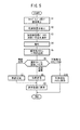
第1実施形態の放射線画像撮影システム10は、基本的には以上のように構成されるものであり、次に、図5及び図6を参照してその動作について説明する。
2. Operation of the First Embodiment The radiographic
撮影システム10は、診察室12に設置されており、例えば、医師18による患者14の診察中において、放射線画像の撮影が必要となった際に使用される。そのため、撮影対象である患者14の患者情報は、撮影に先立ち、コンソール28の患者情報管理部102に予め登録しておく。また、撮影部位や撮影方法、予定撮影枚数が予め決まっている場合には、これらの撮影条件を撮影条件管理部98に予め登録しておく。以上の準備作業が終了した状態において、患者14に対する診察が遂行される。
The
診察中において放射線画像の撮影を行う場合、コンソール28は、医師18又は担当する放射線技師からの撮影開始命令の入力を契機として、受信の確認を要求する受信確認要求信号を所定範囲に送信する。医師18又は担当する放射線技師が、患者14と診察台16との間の所定位置に、照射面36を放射線照射装置22側とした状態でカセッテ24を設置する。この際、カセッテ24は、コンソール28からの受信確認要求信号を受信すると、受信の確認を通知するための受信確認通知信号をコンソール28に対して送信する。これにより、カセッテ24とコンソール28との間で通信が確立される(ステップS1)。
When radiographing is performed during the examination, the
ステップS2において、カセッテ24は、コンソール28からの受信確認要求信号の受信を契機として、電源残量検出部44により電源43の残量RCを検出する。そして、ステップS3において、カセッテ制御部46は、検出された残量RCに基づいて放射線画像データの取扱い方法を選択する。取扱い方法の選択肢としては、無線送信、有線送信及び不揮発性メモリ88への保存がある。
In step S <b> 2, the
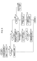
図6は、ステップS3の処理を詳細に示すフローチャートである。ステップS31において、カセッテ制御部46は、放射線画像データの予定撮影枚数を確認する。すなわち、カセッテ制御部46のデータ送受信制御部84は、コンソール28の撮影条件管理部98に対し、予定撮影枚数を問い合せる予定撮影枚数問合せ信号を送信する。この予定撮影枚数問合せ信号に対し、撮影条件管理部98は、予定撮影枚数を通知する予定撮影枚数通知信号を返信する。カセッテ制御部46は、予定撮影枚数通知信号から予定撮影枚数を確認する。
FIG. 6 is a flowchart showing in detail the process of step S3. In step S31, the
ステップS32において、カセッテ制御部46のデータ送受信制御部84は、予定撮影枚数に応じて電源43の残量RCの閾値T1、T2、T3[%](T1>T2>T3)を設定する。閾値T1、T2、T3は、電源43の残量RCの最大値を100%としたときの割合値である。閾値T1は、予定撮影枚数に応じた放射線画像データの全てを無線送信することが可能な残量RCの最低値である。閾値T2は、予定撮影枚数に応じた放射線画像データの一部を無線送信することができないが、有線通信であれば放射線画像データの全てを有線送信することが可能な残量RCの最低値である。閾値T3は、無線通信及び有線通信はできないが、不揮発性メモリ88への保存が可能な残量RCの最低値である。閾値T3を下回る場合、撮影はできない。閾値T1、T2、T3は、例えば、予定撮影枚数が1枚のときに無線送信、有線送信及び不揮発性メモリ88への保存に必要な残量RCの値を予め求めておき、この値に予定撮影枚数を乗算することで算出することができる。或いは、予定撮影枚数毎に、無線送信、有線送信及び不揮発性メモリ88への保存に必要な残量RCの値を予め算出しておいてもよい。
In step S32, the data transmission /
ステップS33において、データ送受信制御部84は、電源残量検出部44が検出した残量RCが、閾値T1以上であるか否かを判定する。残量RCが閾値T1以上である場合、ステップS34において、カセッテ制御部46は、放射線画像データの取扱い方法として「無線送信」を選択する。残量RCが閾値T1未満である場合、ステップS35に進む。
In step S33, the data transmission /
ステップS35において、データ送受信制御部84は、電源残量検出部44が検出した残量RCが、閾値T2以上であるか否かを判定する。残量RCが閾値T2以上である場合、ステップS36において、カセッテ制御部46は、残量RCが不足しており、無線通信でのデータ送信を行うことができないことを通知するメッセージをタッチパネル45に表示する。続くステップS37において、有線通信でのデータ送信又は不揮発性メモリ88への保存のいずれを選択するかを問うメッセージをタッチパネル45に表示する。
In step S <b> 35, the data transmission /
ステップS37において、有線でのデータ通信が選択された場合、ステップS38において、データ送受信制御部84は、タッチパネル45にケーブル49の接続を促すメッセージを表示させ、ステップS39において、ケーブル49が接続されるまでケーブル49の接続の有無を監視する。ケーブル49が接続された場合、ステップS3Aにおいて、カセッテ制御部46は、放射線画像データの取扱い方法として「有線送信」を選択する。
If wired data communication is selected in step S37, in step S38, the data transmission /
ステップS37において、不揮発性メモリ88への保存が選択された場合、後述するステップS3Cに進む。
If saving to the
ステップS35において、残量RCが閾値T2未満である場合、ステップS3Bにおいて、データ送受信制御部84は、電源残量検出部44が検出した残量RCが、閾値T3以上であるか否かを判定する。残量RCが閾値T3以上である場合、ステップS3Cにおいて、データ送受信制御部84は、放射線画像データの取扱い方法として「不揮発性メモリ88への保存」を選択し、ステップS3Dにおいて、当該選択がされた旨、すなわち、カセッテ24内に放射線画像データが保存される旨のメッセージをタッチパネル45に表示する。加えて、当該メッセージをコンソール28を介して表示装置26に表示させることもできる。合わせて、カセッテ24からコンソール28に対し、放射線画像データの取扱い方法として「不揮発性メモリ88への保存」が選択された旨を通知する。これにより、コンソール28は、現時点において、カセッテ24から放射線画像データが送信されてこないことを知ることができる。
In step S35, when the remaining amount RC is less than the threshold value T2, in step S3B, the data transmission /
ステップS3Bにおいて、残量RCが閾値T3未満である場合、ステップS3Eにおいて、カセッテ制御部46は、放射線画像データの取得ができない旨のメッセージをタッチパネル45に表示する。
In step S3B, when the remaining amount RC is less than the threshold value T3, in step S3E, the
図5に戻り、ステップS3において放射線画像データの取扱い方法が選択されると、ステップS4において、医師18により放射線照射装置22がカセッテ24に対向する位置に移動された後、撮影スイッチ72の操作により撮影が行われる。
Returning to FIG. 5, when the radiation image data handling method is selected in step S <b> 3, the
撮影に際し、放射線照射装置22の線源制御部78は、送受信機96、76を介して、コンソール28の撮影条件管理部98より当該患者14の撮影部位に係る撮影条件を取得し、取得した撮影条件に従って放射線源74を制御することにより、所定の線量からなる放射線Xを患者14に照射する。
At the time of imaging, the radiation
患者14を透過した放射線Xは、カセッテ24のグリッド38によって散乱線が除去された後、放射線検出器40に照射され、放射線検出器40を構成する各画素50の光電変換層51によって電気信号に変換され、蓄積容量53に電荷として保持される(図3参照)。次いで、各蓄積容量53に保持された患者14の放射線画像データである電荷情報は、カセッテ制御部46を構成するアドレス信号発生部80からライン走査駆動部58及びマルチプレクサ66に供給されるアドレス信号に従って読み出される。
The radiation X transmitted through the
すなわち、ライン走査駆動部58のアドレスデコーダ60は、アドレス信号発生部80から供給されるアドレス信号に従って選択信号を出力してスイッチSW1の1つを選択し、対応するゲート線54に接続されたTFT52のゲートに制御信号Vonを供給する。一方、マルチプレクサ66のアドレスデコーダ68は、アドレス信号発生部80から供給されるアドレス信号に従って選択信号を出力してスイッチSW2を順次切り替え、ライン走査駆動部58によって選択されたゲート線54に接続された各画素50の蓄積容量53に保持された電荷情報である放射線画像データを信号線56を介して順次読み出す。
That is, the
ステップS5において、カセッテ制御部46は、放射線画像データを揮発性メモリ86に一時的に記録する。すなわち、各放射線検出器40の選択されたゲート線54に接続された各画素50の蓄積容量53から読み出された放射線画像データは、各増幅器62によって増幅された後、各サンプルホールド回路64によってサンプリングされ、マルチプレクサ66を介してA/D変換器70に供給され、デジタル信号に変換される。デジタル信号に変換された放射線画像データは、カセッテ制御部46の揮発性メモリ86に一時的に記録される。
In step S <b> 5, the
同様にして、ライン走査駆動部58のアドレスデコーダ60は、アドレス信号発生部80から供給されるアドレス信号に従ってスイッチSW1を順次切り替え、各ゲート線54に接続されている各画素50の蓄積容量53に保持された電荷情報である放射線画像データを信号線56を介して読み出し、マルチプレクサ66及びA/D変換器70を介してカセッテ制御部46の揮発性メモリ86に記録させる。
Similarly, the
ステップS6において、カセッテ制御部46は、ステップS3で選択された取扱い方法を確認する。ステップS3で無線送信が選択されていた場合、ステップS7において、カセッテ制御部46は、放射線画像データを無線通信によりコンソール28に送信する。ステップS3で有線送信が選択されていた場合、ステップS8において、カセッテ制御部46は、放射線画像データを有線通信によりコンソール28に送信する。
In step S6, the
ステップS7の無線送信又はステップS8の有線送信が行われた場合、ステップS9において、放射線画像データは、表示装置26に表示される。すなわち、カセッテ24からコンソール28に送信された放射線画像データは、送受信機96によって受信され、画像処理部100において所定の画像処理が施された後、患者情報管理部102に登録されている患者14の患者情報と関連付けられた状態で画像メモリ101に記憶される。また、画像処理の施された放射線画像データは、送受信機96から表示装置26に送信される。受信機90によって放射線画像データを受信した表示装置26は、表示制御部92によって表示部94を制御し、放射線画像を表示する。医師18は、表示部94に表示された放射線画像を確認しながら診察を遂行する。
When the wireless transmission in step S7 or the wired transmission in step S8 is performed, the radiation image data is displayed on the
カセッテ24とコンソール28との間で無線通信が行われる場合、両者の間には、信号を送受信するためのケーブル49が連結されていないため、例えば、診察室12の床面にケーブル49が配設されることがなく、医師18等の作業に支障を来すおそれがない。
When wireless communication is performed between the
ステップS3において不揮発性メモリ88への保存が選択されていた場合、ステップS10において、カセッテ制御部46は、放射線画像データを、コンソール28には送信せず、不揮発性メモリ88に保存する。不揮発性メモリ88に保存された放射線画像データは、カセッテ24の電源43を充電又は交換する、カセッテ24に電源ケーブル(図示せず)を接続する等の対応により、電源43の残量RCが増加された後にコンソール28に送信可能である。
If saving to the
3.第1実施形態の効果
以上説明したように、第1実施形態では、カセッテ制御部46のデータ送受信制御部84は、電源43の残量RCが閾値T1未満になったとき、放射線画像データの無線通信を停止し、放射線画像の撮影を優先する。これにより、電源43の残量RCが少なくなったときは、放射線画像の撮影に優先的に電力が供給され、少ない残量RCを有効活用して放射線画像データを取得可能となる。
3. Effects of First Embodiment As described above, in the first embodiment, the data transmission /
また、第1実施形態では、閾値T1が可変とされる。放射線画像の撮影と放射線画像データの無線送信に必要な電力は、予定撮影枚数等の状況に応じて変化する。閾値T1が可変とされることにより、必要な電力に合わせた閾値T1を設定することが可能となる。 In the first embodiment, the threshold value T1 is variable. The power required for radiographic image capture and radiographic data wireless transmission varies depending on the situation such as the planned number of radiographs. By making the threshold value T1 variable, it is possible to set the threshold value T1 according to the required power.
データ送受信制御部84は、無線送信及び有線送信を停止しているとき、放射線画像データを不揮発性メモリ88に記録する。これにより、カセッテ24の電源を切った場合でも、放射線画像データを不揮発性メモリ88に保持し続けることが可能となり、放射線画像データをコンソール28に送信する時期を任意に決めることができる。このため、放射線検出カセッテ24の利便性を向上させることができる。
The data transmission /
データ送受信制御部84は、電源43の残量RCが閾値T1未満且つ閾値T2以上であるとき、放射線画像データを有線通信によりコンソール28に送信する。一般に、有線通信の方が無線通信よりも電力消費量が小さいことから、無線通信により放射線画像データを送信する程の電力が電源43に残っていなくとも、有線通信により放射線画像データを送信することができる。このため、無線通信できないときは常に放射線画像データの送信を停止する場合に比べ、早期に放射線画像データを外部送信できるため、カセッテ24の利便性を向上させることができる。
When the remaining amount RC of the
[B.第2実施形態]
1.放射線画像撮影システム10Aの構成(第1実施形態との相違)
図7は、第2実施形態に係る放射線画像撮影システム10A(以下、「撮影システム10A」とも称する。)の構成ブロック図である。第2実施形態の撮影システム10Aは、第1実施形態の撮影システム10と基本的に同じである。しかし、放射線画像データの取扱い方法(無線送信、有線送信又は不揮発性メモリ88への保存)の選択を、カセッテ24側ではなく、コンソール28側で行う点で、撮影システム10Aは、撮影システム10と異なる。すなわち、撮影システム10Aは、コンソール28にデータ送受信制御部106を有する。また、放射線画像データの取扱い方法の選択(図5のステップS3及び図6のステップS31〜S3E)は、カセッテ24のデータ送受信制御部84ではなく、コンソール28のデータ送受信制御部106で行う。メッセージの表示(図6のステップS36、S38、S3D)は、カセッテ24のタッチパネル45ではなく、表示装置26の表示部94を用いて行う。カセッテ24のデータ送受信制御部84は、電源残量検出部44が検出した残量RCをコンソール28に送信し、また、コンソール28が選択した放射線画像データの取扱い方法を受け、この方法を用いて後の処理を実行する。なお、撮影システム10と同様の構成要素については、同一の参照符号を付し、その説明を省略する。
[B. Second Embodiment]
1. Configuration of radiation
FIG. 7 is a configuration block diagram of a
2.第2実施形態の効果
以上説明したように、第2実施形態では、放射線画像データの取扱い方法の選択を、カセッテ24側ではなく、コンソール28側で行う。これにより、カセッテ24での処理を軽減することができ、カセッテ24の回路構成をより単純なものとすることができる。カセッテ24は患者14の撮影部位に応じて配置位置が変更されることが多いため、コンソール28と比べて軽量化や耐久性の要求が高い。従って、カセッテ24の回路構成をより単純なものとすることができることにより、撮影システム10A全体の性能を向上させることが可能となる。
2. Effects of Second Embodiment As described above, in the second embodiment, the method for handling radiographic image data is selected not on the
[C.第3実施形態]
1.放射線画像撮影システム10Bの構成(第1実施形態との相違)
図8は、第3実施形態に係る放射線画像撮影システム10B(以下、「撮影システム10B」とも称する。)の構成ブロック図である。第3実施形態の撮影システム10Bは、第1実施形態の撮影システム10と基本的に同じである。しかし、緊急撮影用に電源43の残量RCを一定程度確保する構成を有する点で、撮影システム10Bは、撮影システム10と異なる。すなわち、撮影システム10Bでは、カセッテ24が電源残量表示部108を有し、この電源残量表示部108には、電源残量検出部44で検出された残量RCが表示される。ここで、電源残量表示部108は、電源43の残量RCが仮エンプティ値Epまで下がったとき、残量RCがゼロである旨を表示する。仮エンプティ値Epとしては、少なくとも1回の放射線画像データの取得が可能な残量RCを設定可能であり、本実施形態では、例えば、10回の放射線画像データの取得が可能な残量RCが仮エンプティ値Epとされる。
[C. Third Embodiment]
1. Configuration of Radiation
FIG. 8 is a configuration block diagram of a radiographic
また、カセッテ制御部46のデータ送受信制御部84は、電源43の残量RCが仮エンプティ値Epまで下がったとき、電源43に対して放射線検出器40への電力供給の禁止を命令する。この命令を受けた電源43は、図示しないスイッチを切る等の処理により、放射線検出器40への電力供給を停止する。
In addition, the data transmission /
カセッテ24には、緊急撮影ボタン110が設けられており、残量RCが仮エンプティ値Epまで下がっても、撮影者がこの緊急撮影ボタン110を押した場合(換言すると、撮影者から電力供給許可命令を受けたとき)、データ送受信制御部84は、電源43に対して放射線検出器40への電力供給を命令する。この命令を受けた電源43は、前記スイッチを入れる等の処理により、放射線検出器40への電力供給を再開し、電源43の残量RCがゼロになるまで当該電力供給を続ける。
The
2.第3実施形態の効果
以上説明したように、第3実施形態では、電源43の実際の残量RCがゼロでなくとも、仮エンプティ値Epまで下がったことに伴って、電源残量表示部108は、残量RCがゼロである旨を表示する。これにより、放射線画像データの取得を止めるよう撮影者を促すことができ、その結果、少なくとも1回の放射線画像データの取得が可能な状態に電源43が維持されることが期待できる。その結果、放射線画像データを緊急に取得したいときに対応し易くなる。また、電源43の残量RCが少なくなっていることを撮影者に対して通知可能となり、電源43の充電を促すことで電源43の劣化を極力抑えることができる。
2. Advantages of the Third Embodiment As described above, in the third embodiment, the remaining power amount display unit 108 in accordance with the fact that the actual remaining amount RC of the
また、データ送受信制御部84は、電源43の残量RCが仮エンプティ値Epまで下がったとき、電源43から放射線検出器40への電力供給を禁止し、緊急撮影ボタン110が押されたとき、電源43から放射線検出器40への電力供給を許可する。これにより、少なくとも1回の放射線画像データの取得を可能とする電力量の確保がより確実にとなり、緊急時に対応し易くなる。
Further, the data transmission /
[D.変形例]
なお、この発明は、上記各実施形態に限らず、この明細書の記載内容に基づき、種々の構成を採り得ることはもちろんである。例えば、以下に示す1〜5の構成を採ることができる。
[D. Modified example]
The present invention is not limited to the above-described embodiments, and it is needless to say that various configurations can be adopted based on the contents described in this specification. For example, the following
1.放射線画像撮影システム10、10A、10B
上記各実施形態では、撮影システム10、10A、10Bを診察室12内に配置したが、配置する場所はこれに限られない。例えば、回診をするために撮影システム10、10A、10Bを各病室に持ち込んで使用することも可能である。また、撮影システム10、10A、10Bを可動式ではなく、載置式にしてもよい。
1.
In each of the above embodiments, the
上記各実施形態では、撮影システム10をRIS29に接続されるものとしたが、撮影システム10単独で用いてもよい。この場合、コンソール28へのカセッテIDや患者IDの入力は、コンソール28自体に直接行うことができる。
In each of the above embodiments, the
2.放射線変換パネル(放射線検出器40)
上記各実施形態では、放射線検出カセッテ24に収容される放射線検出器40は、入射した放射線Xの線量を光電変換層51によって直接電気信号に変換するものであったが、これに代えて、入射した放射線Xをシンチレータによって一旦可視光に変換した後、この可視光をアモルファスシリコン(a−Si)等の固体検出素子を用いて電気信号に変換するように構成した放射線検出器を用いてもよい(特許第3494683号公報参照)。
2. Radiation conversion panel (radiation detector 40)
In each of the above embodiments, the
また、光変換方式の放射線検出器を利用して放射線画像データを取得することもできる。この光変換方式の放射線検出器では、マトリクス状に配列された各固体検出素子に放射線が入射すると、その線量に応じた静電潜像が固体検出素子に蓄積記録される。静電潜像を読み取る際には、放射線検出器に読取光を照射し、発生した電流の値を放射線画像データとして取得する。なお、放射線検出器は、消去光を放射線検出器に照射することで、残存する静電潜像である放射線画像データを消去して再使用することができる(特開2000−105297号公報参照)。 Also, radiation image data can be obtained using a light conversion type radiation detector. In this light conversion type radiation detector, when radiation is incident on each solid detection element arranged in a matrix, an electrostatic latent image corresponding to the dose is accumulated and recorded in the solid detection element. When reading the electrostatic latent image, the radiation detector is irradiated with reading light, and the value of the generated current is acquired as radiation image data. The radiation detector can erase and reuse the radiation image data, which is a remaining electrostatic latent image, by irradiating the radiation detector with erasing light (see Japanese Patent Laid-Open No. 2000-105297). .
3.電源43及び電源残量検出部44
上記各実施形態では、放射線検出器40、電源残量検出部44、タッチパネル45、カセッテ制御部46及び送受信機48を1つの電源43により駆動したが、複数の電源を用いてこれらの機器を駆動してもよい。この場合、電源残量検出部44を1つ又は複数設け、放射線検出器40を駆動する電源及び送受信機48を駆動する電源の残量RCを検出すればよい。
3.
In each of the above embodiments, the
4.閾値T1、T2、T3
上記各実施形態では、撮影予定枚数に応じて閾値T1、T2、T3を設定したが、閾値T1、T2、T3を設定する要素としては、解像度、感度等を用いることもできる。また、閾値T1、T2、T3のいずれかを用いない構成も可能である。
4). Threshold values T1, T2, T3
In each of the above-described embodiments, the thresholds T1, T2, and T3 are set according to the scheduled number of shots. However, resolution, sensitivity, and the like can be used as elements for setting the thresholds T1, T2, and T3. Further, a configuration that does not use any of the threshold values T1, T2, and T3 is also possible.
5.その他
上記各実施形態では、コンソール28を診察室12内に配置したが、放射線照射装置22、放射線検出カセッテ24及び表示装置26に対して無線通信による信号の送受信を行うことができるのであれば、コンソール28を診察室12の外に設置してもよい。
5. Others In each of the above embodiments, the
上記各実施形態では、カセッテ制御部46は、放射線画像データの無線送信及び有線送信を停止しているとき、放射線画像データを不揮発性メモリ88に記録したが、必ずしも不揮発性メモリ88に記録する必要はない。例えば、揮発性メモリ86に放射線画像データを一時的に記録しておき、その間に、カセッテ24に外部から電力を供給し、その電力を用いて無線送信を行う構成も可能である。
In each of the embodiments described above, the
上記各実施形態では、揮発性メモリ86に放射線画像データを一時的に記録したが、送受信機48を介しての無線送信が高速に行われる場合、又は、不揮発性メモリ88への放射線画像データの記録が高速に行われる場合、揮発性メモリ86を用いない構成も可能である。
In each of the above embodiments, the radiation image data is temporarily recorded in the
上記各実施形態では、無線送信に加え、有線送信を用いて放射線画像データを送信したが、無線送信又は有線送信を用いない構成も可能である。 In each of the above embodiments, radiation image data is transmitted using wired transmission in addition to wireless transmission, but a configuration not using wireless transmission or wired transmission is also possible.
上記各実施形態では、無線送信及び有線送信を停止し、カセッテ24の不揮発性メモリ88に放射線画像データを記録する場合に、カセッテ24のタッチパネル45に当該旨を通知するメッセージを表示した。代わりに、無線送信や有線送信が行われていることを示すLED又は不揮発性メモリ88にデータを保存していることを示すLEDをカセッテ24に設け、これらのLEDの点灯状態や色の変化により放射線画像データの取扱い方法を示すこともできる。
In each of the embodiments described above, when wireless transmission and wired transmission are stopped and radiation image data is recorded in the
第3実施形態では、仮エンプティ値Epまで下がったとき、電源43から放射線検出器40への電力供給を停止したが、電源残量表示部108に残量RCがゼロである旨を表示するのみで、当該電力供給を継続することもできる。
In the third embodiment, the power supply from the
第3実施形態では、緊急撮影用に電源43の残量RCを一定程度確保する構成をカセッテ24内のみで実現させたが、これに限られない。例えば、図9に示す放射線画像撮影システム10C(以下、「撮影システム10C」とも称する。)では、カセッテ24とコンソール28とを用いて、緊急撮影用に電源43の残量RCを一定程度確保する構成を実現している。すなわち、カセッテ24の電源残量検出部44で検出された残量RCは、データ送受信制御部84、送受信機48及び送受信機96を介してコンソール28の撮影条件管理部98に通知され、撮影条件管理部98は、残量RCを電源残量表示部112に表示させる。ここで、電源残量表示部112は、電源43の残量RCが仮エンプティ値Epまで下がったとき、残量RCがゼロである旨を表示する。
In the third embodiment, the configuration that secures the remaining amount RC of the
また、撮影条件管理部98は、電源43の残量RCが仮エンプティ値Epまで下がったとき、データ送受信制御部84に対して、電源43から放射線検出器40への電力供給の禁止を命令する。この命令を受けたデータ送受信制御部84は、電源43を制御して、放射線検出器40への電力供給を停止する。
Further, the imaging
さらに、コンソール28では、図示しないキーボード等により緊急撮影コマンドCeが入力可能であり、撮影者により緊急撮影コマンドCeが入力されると、撮影条件管理部98からデータ送受信制御部84に対し、残量RCが仮エンプティ値Ep以下であっても、電源43から放射線検出器40へと電力供給するよう命令する。この命令を受けたデータ送受信制御部84は、電源43を制御して放射線検出器40への電力供給を再開し、電源43の残量RCがゼロになるまで当該電力供給を続ける。
Further, on the
これにより、電源残量表示部108や緊急撮影ボタン110をカセッテ24に設ける必要がなくなるため、第3実施形態について述べた効果に加え、カセッテ24の小型化及び軽量化を図ることができる。
This eliminates the need to provide the power remaining amount display unit 108 and the
図10に示すように放射線検出カセッテ500(以下、「カセッテ500」と称する。)を構成すると、一層好適である。
As shown in FIG. 10, it is more preferable to configure a radiation detection cassette 500 (hereinafter referred to as “
すなわち、カセッテ500には、ケーシング502の放射線照射面側に、撮影領域及び撮影位置の基準となるガイド線504が形成される。このガイド線504を用いて、カセッテ500に対する被写体(患者14)の位置決めを行い、また、放射線Xの照射範囲を設定することにより、放射線画像情報を適切な撮影領域に記録することができる。
That is, the
カセッテ500の撮影領域外の部位には、当該カセッテ500に係る各種情報を表示する表示部506を配設する。この表示部506には、カセッテ500に記録される患者14のID情報、カセッテ500の使用回数、累積曝射線量、カセッテ500に内蔵されている電源43の充電状態(残容量)、放射線画像情報の撮影条件、患者14のカセッテ500に対するポジショニング画像等を表示させる。この場合、技師は、例えば、表示部506に表示されたID情報に従って患者14を確認するとともに、当該カセッテ500が使用可能な状態にあることを事前に確認し、表示されたポジショニング画像に基づいて患者14の所望の撮影部位をカセッテ500に位置決めして、最適な放射線画像情報の撮影を行うことができる。
A
また、カセッテ500に取手部508を形成することにより、当該カセッテ500の取扱い、持ち運びが容易になる。
Further, by forming the
カセッテ500の側部には、ACアダプタの入力端子510と、USB(Universal Serial Bus)端子512と、メモリカード514を装填するためのカードスロット516とを配設すると好適である。
An AC
入力端子510は、カセッテ500に内蔵されている電源43の充電機能が低下しているとき、あるいは、電源43を充電するのに十分な時間を確保できないとき、ACアダプタを接続して外部から電力を供給することにより、当該カセッテ500を直ちに使用可能な状態とすることができる。
The
USB端子512又はカードスロット516は、カセッテ500がコンソール28等の外部機器との間で無線通信による情報の送受信を行うことができないときに利用することができる。すなわち、USB端子512にケーブルを接続することにより、外部機器との間で有線通信による情報の送受信を行うことができる。また、カードスロット516にメモリカード514を装填し、このメモリカード514に必要な情報を記録した後、メモリカード514を取り出して外部機器に装填することにより、情報の送受信を行うことができる。
The
診察室12や病院内の必要な個所には、図11に示すように、カセッテ24が装填され、内蔵される電源43の充電を行うクレードル518を配置すると好適である。この場合、クレードル518は、電源43の充電だけでなく、クレードル518の無線通信機能又は有線通信機能を用いて、RIS29、HIS31、コンソール28等の外部機器との間で必要な情報の送受信を行うようにしてもよい。送受信する情報には、クレードル518に装填されたカセッテ24に記録された放射線画像情報を含めることができる。
As shown in FIG. 11, a
また、クレードル518に表示部520を配設し、この表示部520に対して、装填された当該カセッテ24の充電状態や、カセッテ24から取得した放射線画像情報を含む必要な情報を表示させるようにしてもよい。
In addition, a
また、複数のクレードル518をネットワークに接続し、各クレードル518に装填されているカセッテ24の充電状態をネットワークを介して収集し、使用可能な充電状態にあるカセッテ24の所在を確認できるように構成することもできる。
Further, a plurality of
10、10A、10B、10C…放射線画像撮影システム
14…患者(被写体)
24、500…放射線検出カセッテ
28…コンソール
40…放射線検出器(放射線変換パネル)
43…電源
44…電源残量検出部(残量検出手段)
48…送受信機(無線通信手段、有線通信手段)
84…データ送受信制御部(制御手段)
86…揮発性メモリ
88…不揮発性メモリ
108、112…電源残量表示部(残量表示手段)
Ep…仮エンプティ値
RC…電源の残量
T1、T2、T3…閾値
X…放射線
10, 10A, 10B, 10C ...
24, 500 ...
43 ...
48 ... transceiver (wireless communication means, wired communication means)
84: Data transmission / reception control unit (control means)
86 ...
Ep ... Temporary empty value RC ... Remaining power T1, T2, T3 ... Threshold X ... Radiation
Claims (1)
前記放射線画像データを無線送信する無線通信手段と、
前記放射線画像データを有線送信する有線通信手段と、
前記放射線変換パネル、前記無線通信手段及び前記有線通信手段を制御する制御手段と、
前記放射線変換パネル、前記無線通信手段及び前記有線通信手段を駆動する電源と、
前記電源の残量を検出する残量検出手段と、
表示部と
を備え、
前記制御手段は、
前記電源の残量が所定の閾値を下回るとき、前記放射線画像データの無線送信を停止し、前記有線通信手段と外部機器とをケーブルで接続することを促すメッセージを前記表示部に表示させ、
前記有線通信手段と前記外部機器との間に前記ケーブルが接続されたとき、前記放射線画像データの有線送信を行う
ことを特徴とする放射線検出カセッテ。 A radiation conversion panel that detects radiation transmitted through the subject and converts it into radiation image data;
Wireless communication means for wirelessly transmitting the radiation image data;
Wired communication means for wired transmission of the radiation image data;
Control means for controlling the radiation conversion panel , the wireless communication means and the wired communication means ;
A power source for driving the radiation conversion panel , the wireless communication means and the wired communication means ;
A remaining amount detecting means for detecting the remaining amount of the power source;
A display unit ,
The control means includes
When the remaining amount of the power source falls below a predetermined threshold, the radio transmission of the radiation image data is stopped , and a message prompting to connect the wired communication unit and an external device with a cable is displayed on the display unit,
The radiation detection cassette , wherein when the cable is connected between the wired communication means and the external device, the radiation image data is wired .
Priority Applications (1)
| Application Number | Priority Date | Filing Date | Title |
|---|---|---|---|
| JP2010004941A JP5031854B2 (en) | 2007-08-16 | 2010-01-13 | Radiation detection cassette |
Applications Claiming Priority (5)
| Application Number | Priority Date | Filing Date | Title |
|---|---|---|---|
| JP2007212244 | 2007-08-16 | ||
| JP2007212244 | 2007-08-16 | ||
| JP2008020106 | 2008-01-31 | ||
| JP2008020106 | 2008-01-31 | ||
| JP2010004941A JP5031854B2 (en) | 2007-08-16 | 2010-01-13 | Radiation detection cassette |
Related Parent Applications (1)
| Application Number | Title | Priority Date | Filing Date |
|---|---|---|---|
| JP2008143454A Division JP4444348B2 (en) | 2007-08-16 | 2008-05-30 | Radiation detection cassette and radiographic imaging system |
Publications (3)
| Publication Number | Publication Date |
|---|---|
| JP2010137058A JP2010137058A (en) | 2010-06-24 |
| JP2010137058A5 JP2010137058A5 (en) | 2010-11-18 |
| JP5031854B2 true JP5031854B2 (en) | 2012-09-26 |
Family
ID=42347671
Family Applications (1)
| Application Number | Title | Priority Date | Filing Date |
|---|---|---|---|
| JP2010004941A Expired - Fee Related JP5031854B2 (en) | 2007-08-16 | 2010-01-13 | Radiation detection cassette |
Country Status (1)
| Country | Link |
|---|---|
| JP (1) | JP5031854B2 (en) |
Families Citing this family (6)
| Publication number | Priority date | Publication date | Assignee | Title |
|---|---|---|---|---|
| JP2010032268A (en) * | 2008-07-25 | 2010-02-12 | Fujifilm Corp | Transportable radiological image conversion apparatus, information processor, and housing apparatus |
| CN104688254B (en) * | 2013-12-06 | 2020-06-09 | Ge医疗系统环球技术有限公司 | Medical portable detector device and working method thereof |
| JP6670089B2 (en) * | 2015-12-18 | 2020-03-18 | キヤノン株式会社 | Radiation imaging system, radiation imaging system control method, and program |
| US10758196B2 (en) | 2015-12-15 | 2020-09-01 | Canon Kabushiki Kaisha | Radiation imaging apparatus, control method for radiation imaging apparatus, and program |
| JP2017136187A (en) * | 2016-02-03 | 2017-08-10 | コニカミノルタ株式会社 | Radiological imaging system |
| KR20210056181A (en) * | 2019-11-08 | 2021-05-18 | 삼성전자주식회사 | Mobile X-ray detector, X-ray imaging apparatus and method for operating the them |
Family Cites Families (2)
| Publication number | Priority date | Publication date | Assignee | Title |
|---|---|---|---|---|
| JP2003251893A (en) * | 2002-03-04 | 2003-09-09 | Canon Inc | Ink jet recorder and its controlling method |
| JP2005007086A (en) * | 2003-06-23 | 2005-01-13 | Canon Inc | X-ray radiographing system |
-
2010
- 2010-01-13 JP JP2010004941A patent/JP5031854B2/en not_active Expired - Fee Related
Also Published As
| Publication number | Publication date |
|---|---|
| JP2010137058A (en) | 2010-06-24 |
Similar Documents
| Publication | Publication Date | Title |
|---|---|---|
| JP4444348B2 (en) | Radiation detection cassette and radiographic imaging system | |
| JP5438903B2 (en) | Radiation detection apparatus and radiographic imaging system | |
| JP5274915B2 (en) | Radiation detection cassette and radiographic imaging system | |
| US7561668B2 (en) | Radiation detecting cassette and radiation image capturing system | |
| JP5785368B2 (en) | Radiation imaging system | |
| US7864923B2 (en) | Radiation detecting cassette and radiation image capturing system | |
| JP5031854B2 (en) | Radiation detection cassette | |
| JP2009045432A (en) | Method of radiography, and radiography system and radiation information system for executing the method of radiography | |
| JP2009034484A (en) | Radiation image capturing system | |
| JP2011177348A (en) | Radiographic image acquiring apparatus, radiographic image capturing system, and radiographic image capturing method | |
| JP5192914B2 (en) | Cassette and radiographic imaging system | |
| JP4945467B2 (en) | Radiation converter cradle | |
| JP4914849B2 (en) | Radiation converter and radiation converter processing apparatus | |
| JP2009181001A (en) | Radiation transducer | |
| JP2009028367A (en) | Radiation image photographing system | |
| JP4862016B2 (en) | Radiation detection cassette and radiographic imaging system | |
| JP2009180537A (en) | Cradle for use with radiation conversion device | |
| JP4987747B2 (en) | Charging cradle and radiographic imaging system using the same | |
| JP5294725B2 (en) | Radiation imaging system | |
| JP4881920B2 (en) | Radiation detection cassette and radiographic imaging system | |
| JP2009180519A (en) | Radiation conversion device | |
| JP2009061256A (en) | Radiation image capturing system, and method of setting transmission radio field intensity in the system | |
| JP2009178499A (en) | Radiation convertor and radiation imaging system | |
| JP2009045433A (en) | Method of radiography, and radiography system and radiation information system for executing the method of radiography | |
| JP2009050690A (en) | Radiographic system and radiation detection cassette |
Legal Events
| Date | Code | Title | Description |
|---|---|---|---|
| A521 | Request for written amendment filed |
Free format text: JAPANESE INTERMEDIATE CODE: A523 Effective date: 20100929 |
|
| A621 | Written request for application examination |
Free format text: JAPANESE INTERMEDIATE CODE: A621 Effective date: 20100929 |
|
| A131 | Notification of reasons for refusal |
Free format text: JAPANESE INTERMEDIATE CODE: A131 Effective date: 20120417 |
|
| TRDD | Decision of grant or rejection written | ||
| A01 | Written decision to grant a patent or to grant a registration (utility model) |
Free format text: JAPANESE INTERMEDIATE CODE: A01 Effective date: 20120612 |
|
| A01 | Written decision to grant a patent or to grant a registration (utility model) |
Free format text: JAPANESE INTERMEDIATE CODE: A01 |
|
| A61 | First payment of annual fees (during grant procedure) |
Free format text: JAPANESE INTERMEDIATE CODE: A61 Effective date: 20120627 |
|
| R150 | Certificate of patent or registration of utility model |
Free format text: JAPANESE INTERMEDIATE CODE: R150 |
|
| FPAY | Renewal fee payment (event date is renewal date of database) |
Free format text: PAYMENT UNTIL: 20150706 Year of fee payment: 3 |
|
| LAPS | Cancellation because of no payment of annual fees |