JP4945467B2 - Radiation converter cradle - Google Patents
Radiation converter cradle Download PDFInfo
- Publication number
- JP4945467B2 JP4945467B2 JP2008016267A JP2008016267A JP4945467B2 JP 4945467 B2 JP4945467 B2 JP 4945467B2 JP 2008016267 A JP2008016267 A JP 2008016267A JP 2008016267 A JP2008016267 A JP 2008016267A JP 4945467 B2 JP4945467 B2 JP 4945467B2
- Authority
- JP
- Japan
- Prior art keywords
- information
- radiation
- cradle
- radiation converter
- subject
- Prior art date
- Legal status (The legal status is an assumption and is not a legal conclusion. Google has not performed a legal analysis and makes no representation as to the accuracy of the status listed.)
- Expired - Fee Related
Links
- 230000005855 radiation Effects 0.000 title claims description 155
- 238000003384 imaging method Methods 0.000 claims description 64
- 238000000034 method Methods 0.000 claims description 17
- 230000001186 cumulative effect Effects 0.000 claims description 5
- 230000007547 defect Effects 0.000 claims description 5
- 238000006243 chemical reaction Methods 0.000 description 28
- 230000005540 biological transmission Effects 0.000 description 16
- 239000003990 capacitor Substances 0.000 description 8
- 238000010586 diagram Methods 0.000 description 7
- 238000001514 detection method Methods 0.000 description 5
- 238000004891 communication Methods 0.000 description 4
- 238000012790 confirmation Methods 0.000 description 4
- 239000007787 solid Substances 0.000 description 4
- 229910021417 amorphous silicon Inorganic materials 0.000 description 3
- 230000002950 deficient Effects 0.000 description 3
- 239000011669 selenium Substances 0.000 description 3
- BUGBHKTXTAQXES-UHFFFAOYSA-N Selenium Chemical compound [Se] BUGBHKTXTAQXES-UHFFFAOYSA-N 0.000 description 2
- 230000001678 irradiating effect Effects 0.000 description 2
- 229910052711 selenium Inorganic materials 0.000 description 2
- 238000001816 cooling Methods 0.000 description 1
- 230000007423 decrease Effects 0.000 description 1
- 230000006870 function Effects 0.000 description 1
- 239000000463 material Substances 0.000 description 1
- 239000011159 matrix material Substances 0.000 description 1
- 238000002360 preparation method Methods 0.000 description 1
- 238000002601 radiography Methods 0.000 description 1
- 239000000126 substance Substances 0.000 description 1
- 239000010409 thin film Substances 0.000 description 1
- 238000011144 upstream manufacturing Methods 0.000 description 1
Images


Classifications
-
- G—PHYSICS
- G03—PHOTOGRAPHY; CINEMATOGRAPHY; ANALOGOUS TECHNIQUES USING WAVES OTHER THAN OPTICAL WAVES; ELECTROGRAPHY; HOLOGRAPHY
- G03B—APPARATUS OR ARRANGEMENTS FOR TAKING PHOTOGRAPHS OR FOR PROJECTING OR VIEWING THEM; APPARATUS OR ARRANGEMENTS EMPLOYING ANALOGOUS TECHNIQUES USING WAVES OTHER THAN OPTICAL WAVES; ACCESSORIES THEREFOR
- G03B42/00—Obtaining records using waves other than optical waves; Visualisation of such records by using optical means
- G03B42/02—Obtaining records using waves other than optical waves; Visualisation of such records by using optical means using X-rays
-
- H—ELECTRICITY
- H02—GENERATION; CONVERSION OR DISTRIBUTION OF ELECTRIC POWER
- H02J—CIRCUIT ARRANGEMENTS OR SYSTEMS FOR SUPPLYING OR DISTRIBUTING ELECTRIC POWER; SYSTEMS FOR STORING ELECTRIC ENERGY
- H02J7/00—Circuit arrangements for charging or depolarising batteries or for supplying loads from batteries
- H02J7/0042—Circuit arrangements for charging or depolarising batteries or for supplying loads from batteries characterised by the mechanical construction
- H02J7/0044—Circuit arrangements for charging or depolarising batteries or for supplying loads from batteries characterised by the mechanical construction specially adapted for holding portable devices containing batteries
Landscapes
- Physics & Mathematics (AREA)
- General Physics & Mathematics (AREA)
- Apparatus For Radiation Diagnosis (AREA)
- Radiography Using Non-Light Waves (AREA)
Description
本発明は、被写体の放射線画像を撮影する撮影装置の近傍に配置され、前記被写体を透過した放射線を検出して画像情報に変換する放射線変換器の充電処理を行う放射線変換器用クレードルに関する。 The present invention relates to a radiation converter cradle that is disposed in the vicinity of an imaging apparatus that captures a radiographic image of a subject and performs a charging process of a radiation converter that detects radiation transmitted through the subject and converts it into image information.
医療分野において、被写体に放射線を照射し、被写体を透過した放射線を放射線変換器に導いて放射線画像を撮影する放射線画像撮影装置が広汎に使用されている。 2. Description of the Related Art In the medical field, radiation image capturing apparatuses that irradiate a subject with radiation and guide the radiation transmitted through the subject to a radiation converter to capture a radiation image are widely used.
この場合、照射された放射線を直接電気信号に変換し、あるいは、放射線をシンチレータで可視光に変換した後、電気信号に変換して読み出すことのできるアモルファスシリコン等からなる固体検出素子を用いた放射線変換器(電子カセッテ)が開発されている(特許文献1参照)。 In this case, the radiation using a solid detection element made of amorphous silicon or the like that can directly convert the irradiated radiation into an electrical signal, or convert the radiation into visible light with a scintillator and then convert it into an electrical signal and read it out. A converter (electronic cassette) has been developed (see Patent Document 1).
ここで、前記放射線変換器には、バッテリを搭載し、持ち運び可能に構成された携帯型のものがある。この場合、搭載するバッテリの容量が大きいと、放射線変換器の重量が増加するため、取り扱いに不具合が生じる。そのため、バッテリの容量を制限して軽量化を図る一方、撮影室内又はその近傍に充電用クレードルを配置し、適時バッテリの充電を行うようにしている。 Here, the radiation converter includes a portable type equipped with a battery and configured to be portable. In this case, if the capacity of the battery to be mounted is large, the weight of the radiation converter increases, which causes a problem in handling. For this reason, the battery capacity is limited to reduce the weight, while a charging cradle is arranged in the photographing room or in the vicinity thereof to charge the battery in a timely manner.
ところで、放射線画像の撮影を行う場合、被写体とその放射線画像を検出する放射線変換器との関係を正しく認識しておく必要がある。また、所望の放射線画像を得るためには、被写体の年齢、性別、体格等の被写体情報に応じた適切な撮影条件を設定して撮影を行う必要がある。通常、これらの被写体情報及び撮影条件は、撮影室の外に配置したコンソールを用いて技師により設定される。この場合、被写体情報及び撮影条件を設定し、撮影室内に放射線変換器を持ち込んで撮影を行う際、撮影装置の近傍で撮影条件等を確認できないと、被写体の撮影部位の設定ミスや被写体の取り違い等が発生してしまうおそれがある。 By the way, when taking a radiographic image, it is necessary to correctly recognize the relationship between the subject and the radiation converter that detects the radiographic image. Further, in order to obtain a desired radiographic image, it is necessary to perform imaging while setting appropriate imaging conditions according to subject information such as age, sex, and physique of the subject. Usually, the subject information and shooting conditions are set by an engineer using a console arranged outside the shooting room. In this case, when setting the subject information and imaging conditions, and taking the radiation converter into the imaging room to perform imaging, if the imaging conditions etc. cannot be confirmed in the vicinity of the imaging apparatus, an erroneous setting of the imaging area of the subject or the removal of the subject will occur. Differences may occur.
そこで、例えば、撮影室内に配置されている医療診断装置に併設したモニタ上に被写体の氏名等を含む検査計画の情報を表示させ、その表示内容を技師及び被写体が確認できるように構成したものがある(特許文献2参照)。 For this reason, for example, an examination plan including information such as the name of the subject is displayed on a monitor provided in the medical diagnostic apparatus arranged in the photographing room, and the display contents can be confirmed by the technician and the subject. Yes (see Patent Document 2).
この場合、特許文献2のように、放射線変換器に相当する検出部が医療診断装置と一体であるときには、モニタに表示された被写体情報に従って被写体を確認できるため、医療診断装置と被写体との関係を考慮するまでもなく、当該医療診断装置によって所望の被写体の放射線画像を取得できることは明らかである。 In this case, as in Patent Document 2, when the detection unit corresponding to the radiation converter is integrated with the medical diagnostic apparatus, the subject can be confirmed according to the subject information displayed on the monitor, so the relationship between the medical diagnostic apparatus and the subject. Obviously, a radiographic image of a desired subject can be acquired by the medical diagnostic apparatus.
しかしながら、携帯型の放射線変換器の場合には、一被写体に対して複数の放射線変換器が存在することがあるため、被写体と放射線変換器との関係を正しく認識していないと、被写体の放射線画像を取り違えてしまう可能性がある。また、適切な撮影条件を設定して放射線画像を撮影し、対象とする被写体の放射線画像を放射線変換器に記録することも困難となる。 However, in the case of a portable radiation converter, there may be a plurality of radiation converters for one subject. Therefore, if the relationship between the subject and the radiation converter is not correctly recognized, the radiation of the subject There is a possibility of mistaking the image. In addition, it is difficult to set an appropriate imaging condition, take a radiographic image, and record the radiographic image of the target subject in the radiation converter.
本発明は、前記の課題に鑑みなされたものであり、撮影装置の近傍において、放射線変換器の充電を行うことができるとともに、被写体情報及び撮影条件を表示させ、その表示内容に従って被写体の適切な放射線画像を撮影することのできる放射線変換器用クレードルを提供することを目的とする。 The present invention has been made in view of the above-described problems. The radiation converter can be charged in the vicinity of the imaging apparatus, and subject information and imaging conditions are displayed. It is an object of the present invention to provide a radiation converter cradle capable of taking a radiation image.
本発明の放射線変換器用クレードルは、被写体の放射線画像を撮影する撮影装置の近傍に配置され、前記被写体を透過した放射線を検出して画像情報に変換する放射線変換器の充電処理を行い、情報記憶部を有する放射線変換器用クレードルであって、
前記放射線変換器に搭載されたバッテリに対する充電処理を行う充電処理部と、
前記被写体に係る被写体情報、及び、前記画像情報を撮影する際の撮影条件を含む情報を、前記被写体情報及び前記撮影条件を設定するコンソールから取得する情報取得部と、
取得した前記情報を表示する表示部と、
撮影前の前記放射線変換器に前記被写体情報を書き込む一方、撮影後の前記放射線変換器から、前記被写体情報、前記画像情報及び前記放射線変換器の使用情報を読み出して前記情報記憶部に記憶する情報読み書き処理部と、
を備えることを特徴とする。
Radiation transducers cradle of the present invention is arranged near the image capturing apparatus for capturing a radiation image of a subject, you have rows charging process of a radiation converter for converting the image information by detecting the radiation transmitted through the subject, information A radiation converter cradle having a storage unit ,
A charge processing unit that performs a charging process on a battery mounted on the radiation converter;
An information acquisition unit that acquires subject information relating to the subject and information including shooting conditions when shooting the image information from a console that sets the subject information and the shooting conditions;
A display unit for displaying the acquired information;
While writing the object information to the radiation converter before shooting, the storage from the radiation transducer after shooting, the subject information, the image information and to read out the usage information of the radiation converter in the information storage unit An information read / write processing unit,
It is characterized by providing.
本発明によれば、撮影装置の近傍に配置された放射線変換器用クレードルの表示部に被写体情報及び撮影条件が表示されるため、技師は、表示されたこれらの情報に従い、所定の被写体であることを確認できるとともに、適切な撮影条件を撮影装置に設定することができる。また、放射線変換器用クレードルに装填されて充電状態にある放射線変換器との関連で、被写体情報及び撮影条件を確認できるため、被写体と放射線変換器との関係を正しく対応させることができる。 According to the present invention, since subject information and imaging conditions are displayed on the display unit of the radiation converter cradle disposed in the vicinity of the imaging apparatus, the engineer is a predetermined subject according to the displayed information. And appropriate photographing conditions can be set in the photographing apparatus. In addition, since the subject information and the imaging conditions can be confirmed in relation to the radiation converter loaded in the radiation converter cradle and in a charged state, the relationship between the subject and the radiation converter can be made to correspond correctly.
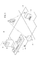
図1は、本発明の放射線変換器用クレードルが適用される放射線画像撮影システム20の説明図である。放射線画像撮影システム20は、撮影条件に従った線量からなる放射線Xを患者22(被写体)に照射する放射線源24と、放射線源24を制御する線源制御装置26と、患者22を透過した放射線Xを検出する電子カセッテ28(放射線変換器)と、電子カセッテ28の充電処理、患者情報(被写体情報)及び撮影条件の表示処理、及び、電子カセッテ28により検出した放射線Xに基づく画像情報の送受信処理を行うクレードル30と、放射線源24の撮影スイッチを有し、撮影作業を含む状態確認のために技師が所持する携帯情報端末32と、線源制御装置26、クレードル30及び携帯情報端末32を制御するとともに、必要な情報の送受信を行うコンソール34とを備える。
FIG. 1 is an explanatory diagram of a radiation image capturing
なお、患者情報とは、患者22の氏名、性別、患者ID番号等、患者22を特定するための情報である。撮影条件とは、患者22の撮影部位に対して、適切な線量からなる放射線Xを照射するための管電圧、管電流、照射時間等を決定するための条件であり、例えば、撮影部位、撮影方法等の条件を挙げることができる。患者情報及び撮影条件は、コンソール34から取得することができる。
The patient information is information for specifying the
放射線源24、線源制御装置26及びクレードル30は、撮影室36内に配置され、コンソール34は、撮影室36外の操作室38に配置される。また、線源制御装置26と携帯情報端末32、携帯情報端末32とコンソール34との間では、無線通信による必要な情報の送受信が行われる。
The
図2は、電子カセッテ28の内部構成図である。電子カセッテ28は、放射線Xを透過させる材料からなるケーシング40を備える。ケーシング40の内部には、放射線Xが照射される照射面側から、患者22による放射線Xの散乱線を除去するグリッド42、患者22を透過した放射線Xを検出する放射線変換パネル44、及び、放射線Xのバック散乱線を吸収する鉛板46が順に配設される。
FIG. 2 is an internal configuration diagram of the
ケーシング40の内部には、電子カセッテ28の電源であるバッテリ50と、バッテリ50から供給される電力により放射線変換パネル44を駆動制御する制御部52と、放射線変換パネル44によって放射線Xから電気信号に変換された情報を含む信号をクレードル30に無線送信する送受信部54とが収容される。なお、制御部52及び送受信部54には、放射線Xが照射されることによる損傷を回避するため、ケーシング40の照射面側に鉛板等を配設しておくことが好ましい。
Inside the
図3は、放射線変換パネル44を含む電子カセッテ28の回路構成ブロック図である。放射線変換パネル44は、放射線Xを感知して電荷を発生させるアモルファスセレン(a−Se)等の物質からなる光電変換層56を行列状の薄膜トランジスタ(TFT:Thin Film Transistor)58のアレイの上に配置した構造を有し、発生した電荷を蓄積容量60に蓄積した後、各行毎にTFT58を順次オンにして、電荷を画像信号として読み出す。図3では、光電変換層56及び蓄積容量60からなる1つの画素62と1つのTFT58との接続関係のみを示し、その他の画素62の構成については省略している。なお、アモルファスセレンは、高温になると構造が変化して機能が低下してしまうため、所定の温度範囲内で使用する必要がある。従って、電子カセッテ28内に放射線変換パネル44を冷却する手段を配設することが好ましい。
FIG. 3 is a circuit configuration block diagram of the
各画素62に接続されるTFT58には、行方向と平行に延びるゲート線64と、列方向と平行に延びる信号線66とが接続される。各ゲート線64は、ライン走査駆動部68に接続され、各信号線66は、読取回路を構成するマルチプレクサ76に接続される。
The TFT 58 connected to each
ゲート線64には、行方向に配列されたTFT58をオンオフ制御する制御信号Von、Voffがライン走査駆動部68から供給される。この場合、ライン走査駆動部68は、ゲート線64を切り替える複数のスイッチSW1と、スイッチSW1の1つを選択する選択信号を出力するアドレスデコーダ70とを備える。アドレスデコーダ70には、制御部52からアドレス信号が供給される。
Control signals Von and Voff for controlling on / off of the
また、信号線66には、列方向に配列されたTFT58を介して各画素62の蓄積容量60に保持されている電荷が流出する。この電荷は、増幅器72によって増幅される。増幅器72には、サンプルホールド回路74を介してマルチプレクサ76が接続される。マルチプレクサ76は、信号線66を切り替える複数のスイッチSW2と、スイッチSW2の1つを選択する選択信号を出力するアドレスデコーダ78とを備える。アドレスデコーダ78には、制御部52からアドレス信号が供給される。マルチプレクサ76には、A/D変換器80が接続され、A/D変換器80によってデジタル信号に変換された放射線画像情報が制御部52に供給される。
In addition, the charge held in the
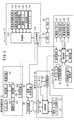
図4は、放射線画像撮影システム20の構成ブロック図である。
FIG. 4 is a configuration block diagram of the radiographic
電子カセッテ28の制御部52には、放射線変換パネル44によって検出された放射線画像情報を記憶する画像メモリ51と、電子カセッテ28の固有の情報であるカセッテ情報を記憶するカセッテ情報メモリ53と、送受信部54と、電子カセッテ28に電力を供給するバッテリ50とが接続される。なお、カセッテ情報とは、例えば、当該電子カセッテ28に対して放射線画像情報を記録した回数である使用回数、電子カセッテ28に曝射された放射線Xの累積曝射線量、放射線変換パネル44を構成する各画素62から得られる放射線画像情報に基づいて検出した欠陥情報を挙げることができる。
The
クレードル30の制御部90には、装填された電子カセッテ28のバッテリ50の充電処理を行う充電処理部92と、電子カセッテ28から取得したカセッテ情報を記憶するカセッテ情報メモリ91と、コンソール34から取得した患者情報及び撮影条件を記憶する患者情報メモリ93及び撮影条件メモリ101と、電子カセッテ28に患者情報を書き込む一方、電子カセッテ28から放射線画像情報を読み出す情報読み書き処理部95と、読み出された放射線画像情報を記憶する画像メモリ97と、患者情報、撮影条件及び取得した放射線画像情報を含む必要な情報を表示する表示部96と、必要な情報を技師等に報知するためのスピーカ98と、電子カセッテ28及びコンソール34との間で情報の送受信を行う送受信部94とが接続される。なお、送受信部94は、電子カセッテ28と無線通信による信号の送受信を行う。また、電子カセッテ28のバッテリ50に対する充電処理は、送受信部94を介した非接触状態、あるいは、クレードル30に装填された電子カセッテ28の図示しないコネクタを介した接触状態で行うことができる。
The
携帯情報端末32の制御部100は、放射線源24を駆動する撮影スイッチ102によって生成された撮影信号を送受信部104を介して線源制御装置26に供給する。また、制御部100は、送受信部104を介してコンソール34から受信した患者情報、撮影条件等を表示部106に表示するとともに、必要な情報をスピーカ108を鳴動させることで技師等に報知する処理を行う。なお、携帯情報端末32は、必要な情報を設定することのできる操作部110を有する。
The
コンソール34は、制御部112と、線源制御装置26、クレードル30及び携帯情報端末32に対して、必要な情報を無線通信により送受信する送受信部114と、患者情報を設定する患者情報設定部116と、線源制御装置26による撮影に必要な撮影条件を設定する撮影条件設定部118と、クレードル30を介して電子カセッテ28から供給された放射線画像情報に対する画像処理を行う画像処理部120と、処理した放射線画像情報を記憶する画像メモリ122と、放射線画像情報及びその他必要な情報を表示する表示部124と、必要な情報を技師等に報知するためのスピーカ126とを備える。
The
コンソール34には、病院内の放射線科において取り扱われる放射線画像情報やその他の情報を統括的に管理する放射線科情報システム(RIS)82が接続され、また、RIS82には、病院内の医事情報を統括的に管理する医事情報システム(HIS)84が接続される。患者情報及び撮影条件を含む撮影のオーダリング情報は、コンソール34で直接設定し、あるいは、RIS82を介してコンソール34に外部から供給することができる。
The
本実施形態の放射線画像撮影システム20は、基本的には以上のように構成されるものであり、次にその動作について説明する。
The radiographic
患者22の放射線画像を撮影する際、コンソール34の患者情報設定部116を用いて当該患者22の患者情報を設定するとともに、撮影条件設定部118を用いて必要な撮影条件を設定する。なお、これらの情報は、送受信部114を介して上流のRIS82、HIS84から取得してもよい。設定された患者情報及び撮影条件は、表示部124に表示して確認することができる。
When capturing a radiographic image of the
次に、設定された患者情報及び撮影条件は、送受信部114から撮影室36内に配置されているクレードル30に送信され、制御部90によってクレードル30の表示部96に表示される。この場合、技師は、表示部96に表示された患者情報に従い、撮影を行う患者22の氏名等を確認する。この確認処理により、患者の取り違い等の事故を未然に回避することができる。また、技師は、表示された撮影条件に従い、撮影部位、撮影方法等の確認を行うことができる。
Next, the set patient information and imaging conditions are transmitted from the transmission /
一方、クレードル30には、撮影に供せられる電子カセッテ28が装填され、充電処理部92によってバッテリ50の充電処理が行われている。情報読み書き処理部95は、この電子カセッテ28のカセッテ情報メモリ53に対して、撮影対象となる患者22に係る患者情報を記録する。
On the other hand, the
また、患者情報及び撮影条件は、コンソール34の送受信部114から無線通信により技師が所持する携帯情報端末32に送信され、その表示部106に表示される。この場合、技師は、携帯情報端末32の表示部106に表示された患者情報及び撮影条件を確認して、所望の撮影準備を行うことができる。
The patient information and imaging conditions are transmitted from the transmission /
さらに、撮影条件は、線源制御装置26に送信される。線源制御装置26は、送信された撮影条件である管電圧、管電流、照射時間を放射線源24に設定し、撮影準備を行う。
Further, the imaging conditions are transmitted to the radiation
技師は、クレードル30の表示部96に表示された患者情報を確認した後、充電処理が完了し、且つ、患者情報が記録された電子カセッテ28をクレードル30から取り出し、指定された撮影条件に従い、患者22の所望の撮影部位に電子カセッテ28を設定する。
After confirming the patient information displayed on the
患者22に対して電子カセッテ28が適切な状態に設定された後、技師は、携帯情報端末32の撮影スイッチ102を操作し、放射線画像の撮影を行う。撮影スイッチ102が操作されると、携帯情報端末32の制御部100は、送受信部104を介して撮影開始信号を線源制御装置26に送信する。撮影開始信号を受信した線源制御装置26は、予めコンソール34から供給されている撮影条件に従って放射線源24を制御し、放射線Xを患者22に照射する。
After the
患者22を透過した放射線Xは、電子カセッテ28のグリッド42によって散乱線が除去された後、放射線変換パネル44に照射され、放射線変換パネル44を構成する各画素62の光電変換層56によって電気信号に変換され、蓄積容量60に電荷として保持される(図3参照)。次いで、各蓄積容量60に保持された患者22の放射線画像情報である電荷情報は、制御部52からライン走査駆動部68及びマルチプレクサ76に供給されるアドレス信号に従って読み出される。
The radiation X transmitted through the
すなわち、ライン走査駆動部68のアドレスデコーダ70は、制御部52から供給されるアドレス信号に従って選択信号を出力してスイッチSW1の1つを選択し、対応するゲート線64に接続されたTFT58のゲートに制御信号Vonを供給する。一方、マルチプレクサ76のアドレスデコーダ78は、制御部52から供給されるアドレス信号に従って選択信号を出力してスイッチSW2を順次切り替え、ライン走査駆動部68によって選択されたゲート線64に接続された各画素62の蓄積容量60に保持された電荷情報である放射線画像情報を信号線66を介して順次読み出す。
That is, the
放射線変換パネル44の選択されたゲート線64に接続された各画素62の蓄積容量60から読み出された放射線画像情報は、各増幅器72によって増幅された後、各サンプルホールド回路74によってサンプリングされ、マルチプレクサ76を介してA/D変換器80に供給され、デジタル信号に変換される。デジタル信号に変換された放射線画像情報は、制御部52に接続された画像メモリ51に一旦記憶される。
The radiation image information read from the
同様にして、ライン走査駆動部68のアドレスデコーダ70は、制御部52から供給されるアドレス信号に従ってスイッチSW1を順次切り替え、各ゲート線64に接続されている各画素62の蓄積容量60に保持された電荷情報である放射線画像情報を信号線66を介して読み出し、マルチプレクサ76及びA/D変換器80を介して制御部52に接続された画像メモリ51に一旦記憶される。
Similarly, the
また、電子カセッテ28の制御部52は、撮影が完了した時点において、当該電子カセッテ28の使用回数、すなわち、放射線Xを曝射した回数をカウントし、カセッテ情報としてカセッテ情報メモリ53に記録する。また、制御部52は、画像メモリ51に記憶された放射線画像情報に基づき、使用開始から今回の撮影までの放射線Xの累積曝射線量を、放射線変換パネル44の各画素62毎、あるいは、各画素62の累積曝射線量の平均値として算出し、カセッテ情報メモリ53に記録する。
Further, the
さらに、制御部52は、画像メモリ51に記憶された放射線画像情報に基づき、例えば、隣接する画素62間の放射線画像情報を比較することにより、欠陥画素の有無、欠陥の程度等に係る欠陥情報を算出し、カセッテ情報メモリ53に記録する。なお、欠陥画素を検出する方法としては、例えば、暗画像(暗電流)を用いる方法、患者22を配置しない状態で所定量の放射線Xを電子カセッテ28に一様に照射(露光)して得られる放射線画像情報を用いる方法、その他、各種の放射線画像撮影装置で実行されている欠陥画素の検出方法を利用することができる(特願2007−84797号[0026]参照)。
Further, the
撮影が完了し、患者22の放射線画像情報が記録された電子カセッテ28は、撮影室36内に配置されているクレードル30に装填され、充電処理部92によりバッテリ50の充電処理が行われるとともに、情報読み書き処理部95により放射線画像情報及びカセッテ情報の読み出し処理が行われる。
The
すなわち、クレードル30の情報読み書き処理部95は、電子カセッテ28の画像メモリ51に記憶された放射線画像情報を読み出して画像メモリ97に記憶させるとともに、電子カセッテ28のカセッテ情報メモリ53に記憶されたカセッテ情報を読み出してカセッテ情報メモリ91及び患者情報メモリ93に記憶させる。これらの情報は、制御部90によって表示部96に表示される。例えば、画像メモリ97から読み出された放射線画像情報をプレビュー画像として表示部96に表示するとともに、カセッテ情報メモリ53から読み出された患者情報を表示部96に表示することにより、所望の患者22に対して適切な撮影が行われたか否かを撮影室36内において確認することができる。また、カセッテ情報メモリ53から読み出された当該電子カセッテ28の使用回数、累積曝射線量、放射線変換パネル44の欠陥情報等を表示部96に表示することにより、電子カセッテ28が適切な使用状態にあるか否かを確認することができる。
That is, the information read / write processing unit 95 of the
一方、クレードル30の画像メモリ97に記憶された放射線画像情報は、患者情報メモリ93に記憶された患者情報とともに、送受信部94を介してコンソール34に送信される。コンソール34では、画像処理部120により放射線画像情報に対する画像処理が施された後、患者情報と関連付けられた状態で画像メモリ122に記憶される。次いで、画像メモリ122に記憶された放射線画像情報は、表示部124に表示されることで、画像の最終確認を行うことができる。
On the other hand, the radiation image information stored in the image memory 97 of the
コンソール34に送信された放射線画像情報は、必要に応じて圧縮処理が施された後、送受信部114から技師が所持する携帯情報端末32に送信され、プレビュー画像として表示部106に表示させるようにしてもよい。また、放射画像情報は、クレードル30又は電子カセッテ28から直接携帯情報端末32に送信するように構成することも可能である。
The radiographic image information transmitted to the
なお、本発明は、上述した実施形態に限定されるものではなく、本発明の主旨を逸脱しない範囲で自由に変更できることは勿論である。 In addition, this invention is not limited to embodiment mentioned above, Of course, it can change freely in the range which does not deviate from the main point of this invention.
例えば、電子カセッテ28に収容される放射線変換パネル44は、入射した放射線Xの線量を光電変換層56によって直接電気信号に変換するものであるが、これに代えて、入射した放射線Xをシンチレータによって一旦可視光に変換した後、この可視光をアモルファスシリコン(a−Si)等の固体検出素子を用いて電気信号に変換するように構成した放射線変換パネルを用いてもよい(特許第3494683号公報参照)。
For example, the
また、光変換方式の放射線変換パネルを利用して放射線画像情報を取得することもできる。この光変換方式の放射線変換パネルでは、マトリクス状に配列された各固体検出素子に放射線が入射すると、その線量に応じた静電潜像が固体検出素子に蓄積記録される。静電潜像を読み取る際には、放射線変換パネルに読取光を照射し、発生した電流の値を放射線画像情報として取得する。なお、放射線変換パネルは、消去光を放射線変換パネルに照射することで、残存する静電潜像である放射線画像情報を消去して再使用することができる(特開2000−105297号公報参照)。 Also, radiation image information can be obtained using a light conversion type radiation conversion panel. In this light conversion type radiation conversion panel, when radiation is incident on each solid detection element arranged in a matrix, an electrostatic latent image corresponding to the dose is accumulated and recorded in the solid detection element. When reading the electrostatic latent image, the radiation conversion panel is irradiated with reading light, and the value of the generated current is acquired as radiation image information. In addition, the radiation conversion panel can erase and reuse the radiation image information which is the remaining electrostatic latent image by irradiating the radiation conversion panel with erasing light (see Japanese Patent Laid-Open No. 2000-105297). .
20…放射線画像撮影システム
22…患者
24…放射線源
26…線源制御装置
28…電子カセッテ
30…クレードル
32…携帯情報端末
34…コンソール
36…撮影室
38…操作室
44…放射線変換パネル
50…バッテリ
51、97、122…画像メモリ
53、91…カセッテ情報メモリ
82…RIS
84…HIS
93…患者情報メモリ
95…情報読み書き処理部
96、106、124…表示部
101…撮影条件メモリ
20 ...
84 ... HIS
93 ... Patient information memory 95 ... Information read /
Claims (7)
前記放射線変換器に搭載されたバッテリに対する充電処理を行う充電処理部と、
前記被写体に係る被写体情報、及び、前記画像情報を撮影する際の撮影条件を含む情報を、前記被写体情報及び前記撮影条件を設定するコンソールから取得する情報取得部と、
取得した前記情報を表示する表示部と、
撮影前の前記放射線変換器に前記被写体情報を書き込む一方、撮影後の前記放射線変換器から、前記被写体情報、前記画像情報及び前記放射線変換器の使用情報を読み出して前記情報記憶部に記憶する情報読み書き処理部と、
を備えることを特徴とする放射線変換器用クレードル。 Disposed in the vicinity of the imaging apparatus for capturing a radiation image of a subject, have rows charging process of a radiation converter for converting by detecting the radiation transmitted through the subject to the image information, in the radiation transducer cradle having an information storage unit There,
A charge processing unit that performs a charging process on a battery mounted on the radiation converter;
An information acquisition unit that acquires subject information relating to the subject and information including shooting conditions when shooting the image information from a console that sets the subject information and the shooting conditions;
A display unit for displaying the acquired information;
While writing the object information to the radiation converter before shooting, the storage from the radiation transducer after shooting, the subject information, the image information and to read out the usage information of the radiation converter in the information storage unit An information read / write processing unit,
A cradle for a radiation converter, comprising:
前記表示部は、前記放射線変換器から読み出した前記画像情報を表示することを特徴とする放射線変換器用クレードル。 The cradle for a radiation converter according to claim 1,
The display unit displays the image information read from the radiation converter, the radiation converter cradle.
前記表示部は、前記放射線変換器から読み出した前記使用情報を表示することを特徴とする放射線変換器用クレードル。 The cradle for a radiation converter according to claim 1,
The display unit displays the usage information read from the radiation converter, the radiation converter cradle.
前記使用情報は、前記放射線変換器の使用回数に係る情報であることを特徴とする放射線変換器用クレードル。 The cradle for a radiation converter according to claim 3,
The radiation converter cradle, wherein the usage information is information relating to the number of times the radiation converter is used.
前記使用情報は、前記放射線変換器に対する前記放射線の累積曝射線量に係る情報であることを特徴とする放射線変換器用クレードル。 The cradle for a radiation converter according to claim 3,
The radiation converter cradle, wherein the use information is information related to a cumulative exposure dose of the radiation to the radiation converter.
前記使用情報は、前記放射線変換器を構成する画素の欠陥情報であることを特徴とする放射線変換器用クレードル。 The cradle for a radiation converter according to claim 3,
The radiation converter cradle characterized in that the use information is defect information of pixels constituting the radiation converter.
さらに、前記放射線変換器から読み出した前記画像情報をコンソールに送信する画像情報送信部を備えることを特徴とする放射線変換器用クレードル。 The cradle for a radiation converter according to claim 1,
The radiation converter cradle further includes an image information transmitting unit that transmits the image information read from the radiation converter to a console.
Priority Applications (2)
| Application Number | Priority Date | Filing Date | Title |
|---|---|---|---|
| JP2008016267A JP4945467B2 (en) | 2008-01-28 | 2008-01-28 | Radiation converter cradle |
| US12/320,322 US8421024B2 (en) | 2008-01-28 | 2009-01-23 | Cradle for use with radiation conversion device |
Applications Claiming Priority (1)
| Application Number | Priority Date | Filing Date | Title |
|---|---|---|---|
| JP2008016267A JP4945467B2 (en) | 2008-01-28 | 2008-01-28 | Radiation converter cradle |
Publications (3)
| Publication Number | Publication Date |
|---|---|
| JP2009175602A JP2009175602A (en) | 2009-08-06 |
| JP2009175602A5 JP2009175602A5 (en) | 2010-09-02 |
| JP4945467B2 true JP4945467B2 (en) | 2012-06-06 |
Family
ID=40898270
Family Applications (1)
| Application Number | Title | Priority Date | Filing Date |
|---|---|---|---|
| JP2008016267A Expired - Fee Related JP4945467B2 (en) | 2008-01-28 | 2008-01-28 | Radiation converter cradle |
Country Status (2)
| Country | Link |
|---|---|
| US (1) | US8421024B2 (en) |
| JP (1) | JP4945467B2 (en) |
Families Citing this family (6)
| Publication number | Priority date | Publication date | Assignee | Title |
|---|---|---|---|---|
| JP2009180537A (en) * | 2008-01-29 | 2009-08-13 | Fujifilm Corp | Cradle for use with radiation conversion device |
| US20130279661A1 (en) * | 2012-04-19 | 2013-10-24 | Canon Kabushiki Kaisha | Radiant ray generation control apparatus, radiation imaging system, and method for controlling the same |
| JP2014230600A (en) * | 2013-05-28 | 2014-12-11 | 株式会社東芝 | X-ray ct apparatus, and x-ray detector for x-ray ct apparatus |
| US20150008867A1 (en) * | 2013-07-03 | 2015-01-08 | At&T Intellectual Property I, L.P. | Charge pump battery charging |
| KR101909486B1 (en) * | 2016-01-05 | 2018-10-18 | 주식회사 바텍 | Charging Cradle Providing Real Time Information And Portable X-ray Imaging Apparatus Comprising The Same |
| JP2019126523A (en) * | 2018-01-24 | 2019-08-01 | コニカミノルタ株式会社 | Radiographic apparatus and radiographic system |
Family Cites Families (21)
| Publication number | Priority date | Publication date | Assignee | Title |
|---|---|---|---|---|
| JP3494683B2 (en) | 1993-11-18 | 2004-02-09 | 富士写真フイルム株式会社 | Radiation detection system, cassette for radiation detector, and radiation image capturing method. |
| EP0727696B1 (en) * | 1995-02-17 | 2003-05-14 | Agfa-Gevaert | Identification system and method for use in the field of digital radiography |
| JP3445164B2 (en) | 1997-08-19 | 2003-09-08 | 富士写真フイルム株式会社 | Electrostatic recording medium, electrostatic latent image recording device, and electrostatic latent image reading device |
| JPH11288051A (en) * | 1998-04-01 | 1999-10-19 | Konica Corp | Case for stimulable phosphor, radiation image reader, and device and method for displaying number of recording or erasing times |
| US6529618B1 (en) * | 1998-09-04 | 2003-03-04 | Konica Corporation | Radiation image processing apparatus |
| DE10118745C2 (en) * | 2001-04-17 | 2003-03-06 | Siemens Ag | X-ray device with portable radiation receiver and mobile central control device |
| JP2004004588A (en) * | 2002-03-22 | 2004-01-08 | Fuji Photo Film Co Ltd | Radiation image information reading apparatus using radiation conversion panel, and sensitivity correction method for the same panel |
| JP2004157271A (en) * | 2002-11-06 | 2004-06-03 | Fuji Photo Film Co Ltd | Photographic information reporting apparatus |
| JP2004287040A (en) | 2003-03-20 | 2004-10-14 | Fuji Photo Film Co Ltd | Method and apparatus for managing image recording medium |
| JP3964354B2 (en) | 2003-06-11 | 2007-08-22 | ジーイー・メディカル・システムズ・グローバル・テクノロジー・カンパニー・エルエルシー | Medical diagnostic equipment |
| DE10344365B4 (en) * | 2003-09-24 | 2007-05-16 | Siemens Ag | X-ray equipment |
| JP2005111054A (en) * | 2003-10-09 | 2005-04-28 | Konica Minolta Medical & Graphic Inc | Fpd photographing system |
| WO2006030593A1 (en) * | 2004-09-16 | 2006-03-23 | Konica Minolta Medical & Graphic, Inc. | Radiation image detector and radiation image photographic system |
| WO2006030592A1 (en) * | 2004-09-16 | 2006-03-23 | Konica Minolta Medical & Graphic, Inc. | Radiation detector and radiation imaging system |
| JP2006208306A (en) | 2005-01-31 | 2006-08-10 | Konica Minolta Medical & Graphic Inc | Radiographic image detector and radiographic image photographing system |
| JP2008134057A (en) * | 2005-03-10 | 2008-06-12 | Konica Minolta Medical & Graphic Inc | Radiation image detector and radiation image photographing system |
| DE102005039887A1 (en) * | 2005-08-23 | 2007-03-08 | Siemens Ag | Solid state detector for recording digital X-ray images |
| US7787014B2 (en) * | 2005-12-19 | 2010-08-31 | General Electric Company | Systems, apparatus and methods for portable imaging |
| WO2007114096A1 (en) * | 2006-04-05 | 2007-10-11 | Konica Minolta Medical & Graphic, Inc. | Diagnosis system |
| JP4908283B2 (en) | 2007-03-28 | 2012-04-04 | 富士フイルム株式会社 | Radiation image capturing apparatus and pixel defect information acquisition method |
| JP2009180537A (en) * | 2008-01-29 | 2009-08-13 | Fujifilm Corp | Cradle for use with radiation conversion device |
-
2008
- 2008-01-28 JP JP2008016267A patent/JP4945467B2/en not_active Expired - Fee Related
-
2009
- 2009-01-23 US US12/320,322 patent/US8421024B2/en not_active Expired - Fee Related
Also Published As
| Publication number | Publication date |
|---|---|
| US8421024B2 (en) | 2013-04-16 |
| US20090189081A1 (en) | 2009-07-30 |
| JP2009175602A (en) | 2009-08-06 |
Similar Documents
| Publication | Publication Date | Title |
|---|---|---|
| JP4444348B2 (en) | Radiation detection cassette and radiographic imaging system | |
| JP5274915B2 (en) | Radiation detection cassette and radiographic imaging system | |
| US8053727B2 (en) | Radiation conversion device and radiation image capturing system using the same | |
| JP2009034484A (en) | Radiation image capturing system | |
| JP4945467B2 (en) | Radiation converter cradle | |
| JP5192914B2 (en) | Cassette and radiographic imaging system | |
| JP5284887B2 (en) | Radiation detection apparatus, radiographic imaging system, and temperature compensation method | |
| JP2009053662A (en) | Cassette | |
| JP5031854B2 (en) | Radiation detection cassette | |
| JP2009181001A (en) | Radiation transducer | |
| US7999234B2 (en) | Cradle for use with radiation conversion device | |
| JP2009186389A (en) | Radioactive ray transducer and cradle for radioactive ray transducer | |
| JP4862016B2 (en) | Radiation detection cassette and radiographic imaging system | |
| JP4987747B2 (en) | Charging cradle and radiographic imaging system using the same | |
| US20090189079A1 (en) | Radiation conversion device | |
| JP5081645B2 (en) | Radiation converter cradle | |
| JP5036576B2 (en) | Radiation imaging system | |
| JP5294725B2 (en) | Radiation imaging system | |
| JP5186323B2 (en) | Radiation detector | |
| US20090194694A1 (en) | Radiation detection apparatus and radiation image capturing system | |
| JP2009061256A (en) | Radiation image capturing system, and method of setting transmission radio field intensity in the system | |
| JP2009178471A (en) | Radiation convertor cradle and radiation image photography system using the same | |
| JP2009172250A (en) | Radiation image photographing system | |
| JP4881920B2 (en) | Radiation detection cassette and radiographic imaging system | |
| JP2010046130A (en) | Radiation image photographing system, radiation converter and photographing stand |
Legal Events
| Date | Code | Title | Description |
|---|---|---|---|
| A521 | Request for written amendment filed |
Free format text: JAPANESE INTERMEDIATE CODE: A523 Effective date: 20100721 |
|
| A621 | Written request for application examination |
Free format text: JAPANESE INTERMEDIATE CODE: A621 Effective date: 20100721 |
|
| A977 | Report on retrieval |
Free format text: JAPANESE INTERMEDIATE CODE: A971007 Effective date: 20110422 |
|
| A131 | Notification of reasons for refusal |
Free format text: JAPANESE INTERMEDIATE CODE: A131 Effective date: 20110517 |
|
| A521 | Request for written amendment filed |
Free format text: JAPANESE INTERMEDIATE CODE: A523 Effective date: 20110707 |
|
| A131 | Notification of reasons for refusal |
Free format text: JAPANESE INTERMEDIATE CODE: A131 Effective date: 20111011 |
|
| A521 | Request for written amendment filed |
Free format text: JAPANESE INTERMEDIATE CODE: A523 Effective date: 20111125 |
|
| TRDD | Decision of grant or rejection written | ||
| A01 | Written decision to grant a patent or to grant a registration (utility model) |
Free format text: JAPANESE INTERMEDIATE CODE: A01 Effective date: 20120214 |
|
| A01 | Written decision to grant a patent or to grant a registration (utility model) |
Free format text: JAPANESE INTERMEDIATE CODE: A01 |
|
| A61 | First payment of annual fees (during grant procedure) |
Free format text: JAPANESE INTERMEDIATE CODE: A61 Effective date: 20120305 |
|
| R150 | Certificate of patent or registration of utility model |
Ref document number: 4945467 Country of ref document: JP Free format text: JAPANESE INTERMEDIATE CODE: R150 Free format text: JAPANESE INTERMEDIATE CODE: R150 |
|
| FPAY | Renewal fee payment (event date is renewal date of database) |
Free format text: PAYMENT UNTIL: 20150309 Year of fee payment: 3 |
|
| R250 | Receipt of annual fees |
Free format text: JAPANESE INTERMEDIATE CODE: R250 |
|
| R250 | Receipt of annual fees |
Free format text: JAPANESE INTERMEDIATE CODE: R250 |
|
| R250 | Receipt of annual fees |
Free format text: JAPANESE INTERMEDIATE CODE: R250 |
|
| R250 | Receipt of annual fees |
Free format text: JAPANESE INTERMEDIATE CODE: R250 |
|
| R250 | Receipt of annual fees |
Free format text: JAPANESE INTERMEDIATE CODE: R250 |
|
| R250 | Receipt of annual fees |
Free format text: JAPANESE INTERMEDIATE CODE: R250 |
|
| LAPS | Cancellation because of no payment of annual fees |