JP5030294B2 - lighting equipment - Google Patents
lighting equipment Download PDFInfo
- Publication number
- JP5030294B2 JP5030294B2 JP2008012431A JP2008012431A JP5030294B2 JP 5030294 B2 JP5030294 B2 JP 5030294B2 JP 2008012431 A JP2008012431 A JP 2008012431A JP 2008012431 A JP2008012431 A JP 2008012431A JP 5030294 B2 JP5030294 B2 JP 5030294B2
- Authority
- JP
- Japan
- Prior art keywords
- side wall
- bridge
- lamp
- fluorescent lamp
- pair
- Prior art date
- Legal status (The legal status is an assumption and is not a legal conclusion. Google has not performed a legal analysis and makes no representation as to the accuracy of the status listed.)
- Expired - Fee Related
Links
Images


Landscapes
- Fastening Of Light Sources Or Lamp Holders (AREA)
Description
本発明は、管状の放電路が長手方向中央部を中心として略同一平面に沿って2重渦巻状に旋回された蛍光ランプを有する照明器具に関するものである。 The present invention relates to a luminaire having a fluorescent lamp in which a tubular discharge path is swirled in a double spiral along substantially the same plane with a central portion in the longitudinal direction as a center.
従来より、放電路が2重渦巻状に旋回された蛍光ランプが知られている(例えば特許文献1参照)。
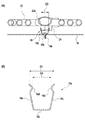
図7(A)、(B)に示すように、特許文献1に記載の蛍光ランプ100は、管状の放電路が長手方向中央部101aを中心として略同一平面に沿って2重渦巻状に旋回された発光管101を有しており、裏面(発光面と反対側)において中央部101aを通って発光管101の両端部101b、101bを連結するブリッジ102が設けられている。また、ブリッジ102の中央部には、裏側に突出して口金103が設けられており、口金103の中央には、ランプピン104が設けられている。
As shown in FIGS. 7A and 7B, in the
しかしながら、前述した特許文献1に記載の蛍光ランプ100では、口金103を照明器具のソケットに嵌合させることにより取り付けているので発光管101の固定を十分に行うことができない。また、口金103に係止爪部を設け、照明器具に設けられているフックに係合して脱落を防止する構造となっているので、口金103の構成を複雑にしているという問題があった。
However, in the
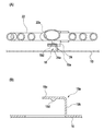
また、図8に示す照明器具110のように、2重渦巻状に旋回された発光管111の両端部に口金112、112を設け、両口金112、112間にブリッジ113を設けた蛍光ランプ114を用いる場合においては、蛍光ランプ114を安定して固定するために、器具本体115にランプ支持バネ116が設けられている。
このため、部品点数が増加して、照明器具110のコストアップを招くという問題があった。
Further, as in the
For this reason, there was a problem that the number of parts increased and the cost of the
本発明は、従来の問題を解決するためになされたもので、簡単な構成で蛍光ランプを安定して固定することのできコストダウンを図ることができる照明器具を提供することを目的とする。 The present invention has been made to solve the conventional problems, and an object of the present invention is to provide a lighting fixture that can stably fix a fluorescent lamp with a simple configuration and can reduce the cost.
本発明の照明器具は、管状の放電路が長手方向中央部を中心として略同一平面に沿って2重渦巻状に旋回された発光管と、前記発光管の両端部にそれぞれ設けられた一対の口金と、前記一対の口金の各々に設けられている一対のランプピンであって、各ランプピンが、前記略同一平面に垂直な方向に配置されると共に、前記発光管の軸方向に沿って延びる一対のランプピンと、前記一対の口金間を連結支持するブリッジとを備えた蛍光ランプと、前記一対のランプピンと電気的に接続されて前記蛍光ランプに電力を供給するとともに、前記一対のランプピンを挿入するためのランプピン挿入溝を有するランプソケットと、前記ランプソケットを介して前記蛍光ランプを保持する器具本体と、を備えた照明器具であって、前記器具本体における前記蛍光ランプに対向する面に、前記ブリッジと係合して前記蛍光ランプの鉛直方向への移動を阻止する係合部が設けられ、前記係合部が、前記ブリッジを押圧する、前記器具本体に固定された弾性部材を有し、前記弾性部材は、断面形状でみて、底面の両側から上方へ向かって、互いに対向する第1側壁および第2側壁が折曲形成され、前記第1側壁および第2側壁の各々には、対向する他方の側壁側へ突出するように折れ曲がった後、逆方向側に折れ曲がって上方にいくほど、対向する他方の側壁から離れる形状をもつ上端部が形成され、各側壁における前記突出するように折れ曲がった部分の頂部が係止部となり、かつ、前記弾性部材は、前記ブリッジと係合する前の状態において、前記第1側壁および前記第2側壁の各々における前記上端同士の間隔が、前記ブリッジの幅よりも大きくなり、かつ、前記第1側壁および前記第2側壁の各々における前記係止部同士の間隔が、前記ブリッジの幅よりも小さくなるように形成され、かつ、前記第1側壁および前記第2側壁の各々が対向する他方の側壁側に付勢されて、前記第1側壁および前記第2側壁が前記ブリッジを挟むようにして保持し、かつ前記係止部によって前記ブリッジの脱落を阻止する構造を有している。 The luminaire of the present invention includes a light emitting tube in which a tubular discharge path is swirled in a double spiral shape along a substantially same plane with a central portion in the longitudinal direction as a center, and a pair of electrodes provided at both ends of the light emitting tube. and the base, a lamp pins of a pair provided on each of the pair of the base, a pair of each lamp pin is, while being arranged in a direction perpendicular to the substantially same plane, extending along the axial direction of the arc tube and the lamp pins of a fluorescent lamp having a bridge connecting support between the pair of the base, along with supplying power to the pair of lamp pins electrically connected to to the fluorescent lamp, inserting the pair of lamp pins a lamp socket having a lamp pins insertion groove for, a luminaire comprising a luminaire main body, the holding of the fluorescent lamp through the lamp socket, in the instrument body The serial surface facing the fluorescent lamp, the engaging portion is provided to the bridge and engaging to prevent movement in the vertical direction of the fluorescent lamp, the engaging portion presses the said bridge, said instrument body The elastic member has a first side wall and a second side wall that are opposed to each other from both sides of the bottom surface upward when viewed in cross-sectional shape, and the first side wall and Each of the second side walls is formed with an upper end having a shape that is bent away from the other side wall as it is bent to protrude toward the other side wall and then bent upward in the opposite direction. The top of each of the side walls bent so as to project becomes a locking portion, and the elastic member is in front of each of the first side wall and the second side wall in a state before being engaged with the bridge. The gap between the upper ends is larger than the width of the bridge, and the gap between the locking portions in each of the first side wall and the second side wall is smaller than the width of the bridge. And each of the first side wall and the second side wall is urged toward the opposite side wall, holds the first side wall and the second side wall sandwiching the bridge, and the locking portion. It has the structure you prevent falling off of the bridge by.
この構成により、器具本体における蛍光ランプに対向する面に、蛍光ランプのブリッジと係合する係合部を設けたので、放電路が長手方向中央部を中心として略同一平面に沿って2重渦巻状に旋回された発光管を有する蛍光ランプをランプソケットに取付けた際に、複数個の支持バネを設けることなく、蛍光ランプの鉛直方向への移動を阻止することができ、照明器具の簡素化およびコストダウンを図ることができる。
また、本発明の照明器具は、前記係合部が、前記ブリッジを押圧する弾性部材を有する構成を有している。
この構成により、弾性部材の復帰力により蛍光ランプのブリッジを両側から挟むとともに、この弾性部材の挿入口をブリッジの幅よりも大きくしておくことにより、ブリッジを弾性部材の挿入口に押し込んで係止することができる。これにより、複数個の支持バネを設けることなく、1個の弾性部材により蛍光ランプの鉛直方向への移動を阻止することができ、照明器具の簡素化およびコストダウンを図ることができる。
With this configuration, since the engagement portion that engages with the bridge of the fluorescent lamp is provided on the surface of the instrument body that faces the fluorescent lamp, the discharge path is a double swirl along substantially the same plane with the central portion in the longitudinal direction as the center. When a fluorescent lamp having an arc tube swung in the shape of a lamp is attached to the lamp socket, it is possible to prevent the fluorescent lamp from moving in the vertical direction without providing a plurality of support springs, thereby simplifying the lighting fixture. In addition, the cost can be reduced.
Moreover, the lighting fixture of this invention has the structure in which the said engaging part has an elastic member which presses the said bridge | bridging.
With this configuration, the bridge of the fluorescent lamp is sandwiched from both sides by the restoring force of the elastic member, and the insertion port of the elastic member is made larger than the width of the bridge so that the bridge is pushed into the insertion port of the elastic member. Can be stopped. Thereby, the movement of the fluorescent lamp in the vertical direction can be prevented by one elastic member without providing a plurality of support springs, and the lighting fixture can be simplified and the cost can be reduced.
さらに、本発明の照明器具は、前記係合部が、前記ブリッジを水平方向から係止する係止部材を有する構成を有している。 Furthermore, the lighting fixture of this invention has the structure in which the said engaging part has a locking member which locks the said bridge from a horizontal direction.
この構成により、例えば蛍光ランプに対向する反射板から蛍光ランプ側へ、先端がL字状に屈曲した係止部材を設け、蛍光ランプを水平方向へ旋回させることにより係止部材の先端に蛍光ランプのブリッジを引っ掛けるようにすることができる。これにより、支持バネを設けることなく、蛍光ランプの鉛直方向への移動を阻止することができ、照明器具の簡素化およびコストダウンを図ることができる。 With this configuration, for example, a locking member whose tip is bent in an L shape is provided from the reflecting plate facing the fluorescent lamp to the fluorescent lamp side, and the fluorescent lamp is pivoted in the horizontal direction to turn the fluorescent lamp at the tip of the locking member. You can try to hook the bridge. Thereby, without providing a support spring, the movement of the fluorescent lamp in the vertical direction can be prevented, and the lighting fixture can be simplified and the cost can be reduced.
本発明は、器具本体における蛍光ランプに対向する面に、蛍光ランプのブリッジと係合する係合部を設けたので、放電路が長手方向中央部を中心として略同一平面に沿って2重渦巻状に旋回された発光管を有する蛍光ランプをランプソケットに取付けた際に、複数個の支持バネを設けることなく、蛍光ランプの鉛直方向への移動を阻止することができ、照明器具の簡素化およびコストダウンを図ることができるという効果を有する照明器具を提供することができるものである。 In the present invention, since the engaging portion that engages with the bridge of the fluorescent lamp is provided on the surface of the instrument body that faces the fluorescent lamp, the discharge path is a double swirl along substantially the same plane centering on the longitudinal center portion. When a fluorescent lamp having an arc tube swung in the shape of a lamp is attached to the lamp socket, it is possible to prevent the fluorescent lamp from moving in the vertical direction without providing a plurality of support springs, thereby simplifying the lighting fixture. And the lighting fixture which has the effect that cost reduction can be aimed at can be provided.
以下、本発明の実施の形態の照明器具について、図面を用いて説明する。
図1は本発明の第1実施形態にかかる照明器具を示す分解斜視図、図2(A)は平面らせん形蛍光灯の平面図、図2(B)は図2(A)中B方向から見た正面図、図3はランプソケットの斜視図、図4(A)は平面らせん形蛍光灯を取付けた状態を示す断面図、図4(B)は弾性部材の断面図である。
Hereinafter, the lighting fixture of embodiment of this invention is demonstrated using drawing.
FIG. 1 is an exploded perspective view showing a lighting apparatus according to a first embodiment of the present invention, FIG. 2A is a plan view of a flat spiral fluorescent lamp, and FIG. 2B is a view from B direction in FIG. FIG. 3 is a perspective view of the lamp socket, FIG. 4A is a sectional view showing a state in which a flat spiral fluorescent lamp is attached, and FIG. 4B is a sectional view of an elastic member.
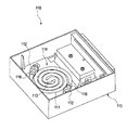
図1に示すように、本発明にかかる照明器具10は、天井や壁等の壁面11に固定して使用するものであり、例えば矩形箱状の器具本体12と、器具本体12の前面開口を覆う透明あるいは半透明の樹脂等からなるパネル13を有している。器具本体12の底板12aには、一方の端部寄りに商用交流電源(図示省略)に接続されている点灯装置14等の電気部品が取付けられており、点灯装置14等を覆うとともにパネル13を取付けるための取付板15が設けられている。パネル13は、ネジ13aを取付板15のネジ穴15aに螺合し、締め付けることにより着脱可能に取付けられる。
As shown in FIG. 1, a
また、底板12の中央部および他方の端部よりには、蛍光ランプとしての平面らせん形蛍光灯20の照明光をパネル13側に反射して照明効率を向上させる反射板16が設けられており、反射板16の上面に、平面らせん形蛍光灯20を装着するための一対のランプソケット17、17が取付けられている。これらランプソケット17、17は、電源線(図示省略)によって、点灯装置14に接続されている。そして、器具本体12における平面らせん形蛍光灯20に対向する面である反射板16の上面には、平面らせん形蛍光灯20をランプソケット17に装着した際に、平面らせん形蛍光灯20の後述するブリッジ24と係合して平面らせん形蛍光灯20の鉛直方向への移動を阻止する係合部18を1個設けた。なお、係合部18は弾性部材18aを有しており、弾性部材18はブリッジ24の中心部付近を保持するように設けるのが望ましい。
Further, a
図2に示すように、平面らせん形蛍光灯20は、管状の放電路が長手方向中央部22aを始点として同一平面に沿って2重渦巻状に旋回された発光管22を有しており、発光管22の中央部22aは、その他の部分に比して太径となっており、最冷点となっている。発光管22の両端部にはそれぞれ口金23、23が取付けられており、両口金23、23は、発光管22の中央部22aに対して、点対称の位置に設けられている。なお、両口金23、23は、照射方向と反対側の裏面に設けられたブリッジ24によって連結されている。また、各口金23、23には、平面らせん形蛍光灯20の平面に直交する方向に一対のランプピン21が、発光管22の軸方向に沿って突出して設けられている。
As shown in FIG. 2, the flat spiral
図3に示すように、ランプソケット17は、例えば円柱状の本体17aを有しており、本体17aにはランプピン21を挿入するためのランプピン挿入溝17bが設けられている。ランプピン挿入溝17bの内部には、一対のランプピン21、21を保持して導通するために一対の導電板17c、17cが設けられている。また、本体17aの外周面に沿ってランプピン挿入溝17bを閉じる開閉蓋17dが設けられている。
As shown in FIG. 3, the
図4に示すように、係合部18を構成する弾性部材18aは、底面18bの両側から上方へ向かって側壁18c、18cが折曲形成されており、側壁18cの上端部には、対向する側壁18c側へ突出して係止部18dが設けられている。弾性部材18aは、ブリッジ24と係合する前の状態において、対向する側壁18c、18cの上端の間隔D1がブリッジ24の幅D2よりも大きくなっており、且つ、係止部18d、18dの間隔D3がブリッジ24の幅D2よりも小さくなるように形成されている。また、弾性部材18は、底面18bをネジ18eで反射板16に固定することにより取付けられており、両側壁18c、18cは、互いに対向する側壁18c側へ付勢されている。
As shown in FIG. 4, the
従って、平面らせん形蛍光灯20を器具本体12に取付ける際には、平面らせん形蛍光灯20の両端の口金23、23に設けられているランプピン21、21を、ランプソケット17のランプピン挿入溝17aに位置決めする。そして、平面らせん形蛍光灯20をランプソケット17の内部に挿入するとともに、ブリッジ24を反射板16に設けられている弾性部材18の内部に押し込む。ブリッジ24を弾性部材18の上方から押し込むと、ブリッジ24は両側壁18c、18cの上端部を開きながら下降し、係止部18dを越えて下降した後は、ブリッジ24の側面を挟んで保持するとともに係止部18dにより脱落を阻止することになる。その後、ランプソケット17の取っ手17eを操作して開閉蓋17dを閉じることにより固定する。
Therefore, when the flat spiral
以上、説明した照明器具10によれば、器具本体12における平面らせん形蛍光灯20に対向する反射板16に、平面らせん形蛍光灯20プのブリッジ24と係合する弾性部材18aを有する係合部18を設けたので、平面らせん形蛍光灯20をランプソケット17に取付ける際に、従来のように複数個の支持バネを設けることなく、平面らせん形蛍光灯20の鉛直方向への移動を阻止することができ、照明器具10の簡素化およびコストダウンを図ることができる。
また、弾性部材18aは平面らせん形蛍光灯20の位置決めの役割を果たしており、ランプピン21とランプソケット17の不完全接触やランプピン21の露出を防止している。
As described above, according to the
Further, the
次に、本発明の第2の実施の形態について、図面を用いて説明する。
図5は本発明の第2実施形態にかかる照明器具を示す分解斜視図、図6(A)は装着された平面らせん形蛍光灯の支持状態を示す断面図、図6(B)は係止部材の断面図である。なお、前述した第1実施形態にかかる照明器具と共通する部位には同じ符号を付して、重複する説明を省略することとする。
Next, a second embodiment of the present invention will be described with reference to the drawings.
FIG. 5 is an exploded perspective view showing a lighting apparatus according to a second embodiment of the present invention, FIG. 6A is a cross-sectional view showing a support state of a mounted flat spiral fluorescent lamp, and FIG. It is sectional drawing of a member. In addition, suppose that the same code | symbol is attached | subjected to the site | part common to the lighting fixture concerning 1st Embodiment mentioned above, and the overlapping description is abbreviate | omitted.
図5および図6に示すように、本発明の第2実施形態にかかる照明器具10Bは、器具本体12における平面らせん形蛍光灯20に対向する面である反射板16に、平面らせん形蛍光灯20のブリッジ24に係合する係合部19として、ブリッジ24を水平方向から係止する係止部材19aを設けたものである。なお、係止部材19aは、平面らせん形蛍光灯20をランプソケット17に装着した際に、ブリッジ24の下方に位置する場所に設けるようにする。また、係止部材19aは、ブリッジ24の中心に対して略対称な位置に複数個(ここでは、2個)設けるのが望ましい。
As shown in FIGS. 5 and 6, a
図6(B)に示すように、係止部材19aは、反射板16を切り起こして上方へ曲げ上げた立壁19bと、立壁19bの上端から水平に曲げた水平部19cを有しており、水平部19cの下面には、下方へ突出した凸部19dが設けられている。なお、ブリッジ24には、凸部19dが嵌入する凹部24a(図6(B)参照)を設けるのが望ましい。
As shown in FIG. 6 (B), the locking
従って、平面らせん形蛍光灯20を器具本体12に取付ける際には、まず平面らせん形蛍光灯20を係止部材19aの水平部19cの下方まで押し下げる。次いで、ランプピン21がランプソケット17のランプピン挿入溝17bに挿入されるように水平方向(図5において時計方向)に旋回させて、ランプピン21をランプソケット17に接続するとともに係止部材19aによってブリッジ24を係止する。その後、ランプソケット17の取っ手17eを操作して開閉蓋17dを閉じることにより固定する。
Therefore, when the flat spiral
以上、説明した照明器具10Bによれば、器具本体12における平面らせん形蛍光灯20に対向する面である反射板16に、切起しにより先端がL字状に屈曲した係止部材19aを設け、平面らせん形蛍光灯20を水平方向へ旋回させることにより係止部材19aの先端に平面らせん形蛍光灯20のブリッジ24を引っ掛けるようにしたので、従来のように支持バネを設けることなく、平面らせん形蛍光灯20の鉛直方向への移動を阻止することができ、照明器具10Bの簡素化およびコストダウンを図ることができる。
As described above, according to the
なお、本発明の照明器具は、前述した各実施形態に限定されるものでなく、適宜な変形,改良等が可能である。
例えば、前述した各実施形態においては、矩形箱状の器具本体12を例示したが、これに限らず、例えば円形箱状等にも適用できる。
In addition, the lighting fixture of this invention is not limited to each embodiment mentioned above, A suitable deformation | transformation, improvement, etc. are possible.
For example, in each embodiment mentioned above, although the rectangular box-shaped instrument
10、10B 照明器具
12 器具本体
16 反射板(対向する面)
17 ランプソケット
18 係合部
18a 弾性部材
19 係合部
19a 係止部材
20 平面らせん形蛍光灯(蛍光ランプ)
21 ランプピン
22 発光管
23 口金
24 ブリッジ
10,
17
21
Claims (2)
前記一対のランプピンと電気的に接続されて前記蛍光ランプに電力を供給するとともに、前記一対のランプピンを挿入するためのランプピン挿入溝を有するランプソケットと、
前記ランプソケットを介して前記蛍光ランプを保持する器具本体と、を備えた照明器具であって、
前記器具本体における前記蛍光ランプに対向する面に、前記ブリッジと係合して前記蛍光ランプの鉛直方向への移動を阻止する係合部が設けられ、
前記係合部が、前記ブリッジを押圧する、前記器具本体に固定された弾性部材を有し、
前記弾性部材は、断面形状でみて、
底面の両側から上方へ向かって、互いに対向する第1側壁および第2側壁が折曲形成され、
前記第1側壁および第2側壁の各々には、対向する他方の側壁側へ突出するように折れ曲がった後、逆方向側に折れ曲がって上方にいくほど、対向する他方の側壁から離れる形状をもつ上端部が形成され、
各側壁における前記突出するように折れ曲がった部分の頂部が係止部となり、
かつ、前記弾性部材は、前記ブリッジと係合する前の状態において、前記第1側壁および前記第2側壁の各々における前記上端同士の間隔が、前記ブリッジの幅よりも大きくなり、かつ、前記第1側壁および前記第2側壁の各々における前記係止部同士の間隔が、前記ブリッジの幅よりも小さくなるように形成され、
かつ、前記第1側壁および前記第2側壁の各々が対向する他方の側壁側に付勢されて、前記第1側壁および前記第2側壁が前記ブリッジを挟むようにして保持し、かつ前記係止部によって前記ブリッジの脱落を阻止することを特徴とする照明器具。 An arc tube in which a tubular discharge path is swirled in a double spiral along substantially the same plane centering on the longitudinal center, a pair of caps provided at both ends of the arc tube, and the pair of caps A pair of lamp pins provided in each of the lamp pins, each lamp pin being disposed in a direction perpendicular to the substantially same plane and extending along the axial direction of the arc tube, and the pair of lamp pins A fluorescent lamp having a bridge for connecting and supporting the caps;
With supplying power to the fluorescent lamp are connected the pair of lamp pins electrically, the lamp socket having a lamp pins insertion groove for inserting the pair of lamp pins,
A fixture body that holds the fluorescent lamp via the lamp socket, and a lighting fixture comprising:
An engagement portion that engages with the bridge to prevent the fluorescent lamp from moving in the vertical direction is provided on a surface of the instrument body that faces the fluorescent lamp .
The engaging portion has an elastic member fixed to the instrument body that presses the bridge,
The elastic member is a cross-sectional shape,
A first side wall and a second side wall facing each other are bent from both sides of the bottom surface upward,
Each of the first side wall and the second side wall has an upper end having a shape that is bent so as to protrude toward the other side wall and then is bent in the opposite direction and is further away from the other side wall. Part is formed,
The top part of each side wall that is bent so as to protrude is a locking part,
In the state before the elastic member is engaged with the bridge, an interval between the upper ends of each of the first side wall and the second side wall is larger than a width of the bridge, and The interval between the locking portions in each of the first side wall and the second side wall is formed to be smaller than the width of the bridge,
And each of the said 1st side wall and the said 2nd side wall is urged | biased by the other side wall side which opposes, The said 1st side wall and the said 2nd side wall hold | maintain the said bridge | bridging, and by the said latching | locking part luminaire characterized that you prevent falling off of the bridge.
Priority Applications (1)
| Application Number | Priority Date | Filing Date | Title |
|---|---|---|---|
| JP2008012431A JP5030294B2 (en) | 2008-01-23 | 2008-01-23 | lighting equipment |
Applications Claiming Priority (1)
| Application Number | Priority Date | Filing Date | Title |
|---|---|---|---|
| JP2008012431A JP5030294B2 (en) | 2008-01-23 | 2008-01-23 | lighting equipment |
Publications (2)
| Publication Number | Publication Date |
|---|---|
| JP2009176501A JP2009176501A (en) | 2009-08-06 |
| JP5030294B2 true JP5030294B2 (en) | 2012-09-19 |
Family
ID=41031397
Family Applications (1)
| Application Number | Title | Priority Date | Filing Date |
|---|---|---|---|
| JP2008012431A Expired - Fee Related JP5030294B2 (en) | 2008-01-23 | 2008-01-23 | lighting equipment |
Country Status (1)
| Country | Link |
|---|---|
| JP (1) | JP5030294B2 (en) |
Families Citing this family (3)
| Publication number | Priority date | Publication date | Assignee | Title |
|---|---|---|---|---|
| JP2011049006A (en) * | 2009-08-26 | 2011-03-10 | Panasonic Electric Works Co Ltd | Lighting fixture |
| JP2011090994A (en) * | 2009-10-26 | 2011-05-06 | Panasonic Electric Works Co Ltd | Lighting fixture |
| JP2011090993A (en) * | 2009-10-26 | 2011-05-06 | Panasonic Electric Works Co Ltd | Lighting fixture |
Family Cites Families (2)
| Publication number | Priority date | Publication date | Assignee | Title |
|---|---|---|---|---|
| JPH04249807A (en) * | 1990-12-26 | 1992-09-04 | Toshiba Lighting & Technol Corp | Luminaire |
| JP2007273330A (en) * | 2006-03-31 | 2007-10-18 | Matsushita Electric Ind Co Ltd | Fluorescent lamp |
-
2008
- 2008-01-23 JP JP2008012431A patent/JP5030294B2/en not_active Expired - Fee Related
Also Published As
| Publication number | Publication date |
|---|---|
| JP2009176501A (en) | 2009-08-06 |
Similar Documents
| Publication | Publication Date | Title |
|---|---|---|
| JP4230923B2 (en) | Lamp holder with lamp and locking means around it | |
| JP2014220034A (en) | Lighting apparatus, light source component, and mounting component | |
| JP5030294B2 (en) | lighting equipment | |
| JP2009176657A (en) | Lighting fixture | |
| JP5094437B2 (en) | lighting equipment | |
| JP4951539B2 (en) | lighting equipment | |
| KR20210041780A (en) | Electric-shock preventing base for led lamp | |
| JP5078088B2 (en) | Lamp socket and lighting apparatus using the lamp socket | |
| JP5172626B2 (en) | lighting equipment | |
| JP4678378B2 (en) | lighting equipment | |
| JP5014180B2 (en) | lighting equipment | |
| KR101060966B1 (en) | Lighting equipment | |
| JP2011090994A (en) | Lighting fixture | |
| JP2007109586A (en) | Luminaire | |
| JP4720754B2 (en) | lighting equipment | |
| JP5328238B2 (en) | Flat spiral fluorescent lamp and luminaire | |
| JP5027700B2 (en) | lighting equipment | |
| JP5147122B2 (en) | lighting equipment | |
| JP2015138677A (en) | Lighting unit | |
| JP4710946B2 (en) | lighting equipment | |
| JP2011216287A (en) | Lighting fixture | |
| JP2011090928A (en) | Lighting fixture | |
| JP2008235215A (en) | Fluorescent lamp, socket, and luminaire | |
| JP2008204735A (en) | Lighting apparatus | |
| JP2010009881A (en) | Lighting apparatus |
Legal Events
| Date | Code | Title | Description |
|---|---|---|---|
| A621 | Written request for application examination |
Free format text: JAPANESE INTERMEDIATE CODE: A621 Effective date: 20101022 |
|
| A711 | Notification of change in applicant |
Free format text: JAPANESE INTERMEDIATE CODE: A712 Effective date: 20120111 |
|
| A977 | Report on retrieval |
Free format text: JAPANESE INTERMEDIATE CODE: A971007 Effective date: 20120315 |
|
| A131 | Notification of reasons for refusal |
Free format text: JAPANESE INTERMEDIATE CODE: A131 Effective date: 20120321 |
|
| A521 | Written amendment |
Free format text: JAPANESE INTERMEDIATE CODE: A523 Effective date: 20120509 |
|
| TRDD | Decision of grant or rejection written | ||
| A01 | Written decision to grant a patent or to grant a registration (utility model) |
Free format text: JAPANESE INTERMEDIATE CODE: A01 Effective date: 20120529 |
|
| A01 | Written decision to grant a patent or to grant a registration (utility model) |
Free format text: JAPANESE INTERMEDIATE CODE: A01 |
|
| A61 | First payment of annual fees (during grant procedure) |
Free format text: JAPANESE INTERMEDIATE CODE: A61 Effective date: 20120625 |
|
| R150 | Certificate of patent or registration of utility model |
Free format text: JAPANESE INTERMEDIATE CODE: R150 |
|
| FPAY | Renewal fee payment (event date is renewal date of database) |
Free format text: PAYMENT UNTIL: 20150706 Year of fee payment: 3 |
|
| LAPS | Cancellation because of no payment of annual fees |