JP5029552B2 - Protective member and image forming apparatus using the same - Google Patents

Protective member and image forming apparatus using the same Download PDF

Info

Publication number
JP5029552B2
JP5029552B2 JP2008239723A JP2008239723A JP5029552B2 JP 5029552 B2 JP5029552 B2 JP 5029552B2 JP 2008239723 A JP2008239723 A JP 2008239723A JP 2008239723 A JP2008239723 A JP 2008239723A JP 5029552 B2 JP5029552 B2 JP 5029552B2
Authority
JP
Japan
Prior art keywords
image forming
forming apparatus
main body
protected
apparatus main
Prior art date
Legal status (The legal status is an assumption and is not a legal conclusion. Google has not performed a legal analysis and makes no representation as to the accuracy of the status listed.)
Expired - Fee Related
Application number
JP2008239723A
Other languages
Japanese (ja)
Other versions
JP2010072348A (en
Inventor
有周 田中
邦明 田中
Current Assignee (The listed assignees may be inaccurate. Google has not performed a legal analysis and makes no representation or warranty as to the accuracy of the list.)
Fujifilm Business Innovation Corp
Original Assignee
Fuji Xerox Co Ltd
Fujifilm Business Innovation Corp
Priority date (The priority date is an assumption and is not a legal conclusion. Google has not performed a legal analysis and makes no representation as to the accuracy of the date listed.)
Filing date
Publication date
Application filed by Fuji Xerox Co Ltd, Fujifilm Business Innovation Corp filed Critical Fuji Xerox Co Ltd
Priority to JP2008239723A priority Critical patent/JP5029552B2/en
Publication of JP2010072348A publication Critical patent/JP2010072348A/en
Application granted granted Critical
Publication of JP5029552B2 publication Critical patent/JP5029552B2/en
Expired - Fee Related legal-status Critical Current
Anticipated expiration legal-status Critical

Links

Images

Landscapes

  • Electrophotography Configuration And Component (AREA)

Description

本発明は、画像形成装置本体に対して着脱自在に形成された、例えば帯電ユニット等の着脱ユニットを画像形成装置本体に対して着脱する際の保護部材及びこれを用いた画像形成装置に関する。   The present invention relates to a protection member that is detachably attached to an image forming apparatus main body, for example, a detachable unit such as a charging unit, and an image forming apparatus using the same.

特開平8−292706号公報JP-A-8-292706 特開2007−240661号公報JP 2007-240661 A

従来、電子写真方式や静電記録方式を用いた画像形成装置では、画像形成処理に寄与する感光ドラムや帯電器、あるいはクリーニング体などの構成機器を経時的に交換する必要が生じるため、かかる構成機器を画像形成装置本体に対して交換可能なように着脱自在にユニット構成した画像形成装置が知られている(例えば、特許文献1,2参照)。   Conventionally, in an image forming apparatus using an electrophotographic method or an electrostatic recording method, it is necessary to replace components such as a photosensitive drum, a charger, or a cleaning body that contribute to image forming processing over time. 2. Description of the Related Art There is known an image forming apparatus in which a device is configured to be detachable so as to be replaceable with respect to an image forming apparatus main body (for example, see Patent Documents 1 and 2).

ここで、特許文献1には、感光体と周辺機器とを一体化して交換可能に形成したいわゆるプロセスカートリッジを画像形成装置本体へ装着する際に、当該プロセスカートリッジを保護/案内するカバー部材についての発明が開示されている。   Here, Patent Document 1 discloses a cover member that protects / guides a process cartridge when a so-called process cartridge, in which a photosensitive member and peripheral devices are integrated and replaceable, is mounted on the main body of the image forming apparatus. The invention is disclosed.

また、特許文献2には、カバー部材の内部に収容したプロセスカートリッジを画像形成装置本体へ装着する際に、当該プロセスカートリッジの装着動作に伴ってカバー部材とプロセスカートリッジとの係合が解除される発明が開示されている。   Further, in Patent Document 2, when a process cartridge housed in a cover member is mounted on the image forming apparatus main body, the engagement between the cover member and the process cartridge is released along with the mounting operation of the process cartridge. The invention is disclosed.

本発明の目的とするところは、被保護部材を画像形成装置本体に対して装着するときと取り外すときの双方において用いることができる保護部材を提供することである。   An object of the present invention is to provide a protective member that can be used both when the protected member is attached to and removed from the image forming apparatus main body.

上記目的を達成するために、請求項1に記載された保護部材は、画像形成装置本体に対して着脱自在に形成された被保護部材を内部に収容し保護する保護部と、前記操作部の前記装着方向の移動に伴って前記保護部に収容された被保護部材を押入れる押入部と、前記操作部が前記装着方向の端部に位置する状態では前記装着方向で前記被保護部材と重複しない位置に位置し、且つ、前記操作部の前記装着方向に対して逆方向の移動に伴って前記装着方向で前記被保護部材と重複する位置に移動し、前記前記保護部に収容された被保護部材を引入れる引入部とを有し、前記被保護部材を移動させるときに操作する操作部材とを備えたことを特徴とするものである。   In order to achieve the above object, a protection member described in claim 1 includes a protection unit that accommodates and protects a protected member that is detachably formed with respect to the image forming apparatus main body, and a protection member. A push-in portion that pushes in the protected member accommodated in the protection portion as the mounting direction moves, and the operation portion overlaps with the protected member in the mounting direction in a state where the operation portion is positioned at the end in the mounting direction. Is moved to a position overlapping with the member to be protected in the mounting direction as the operation unit moves in a direction opposite to the mounting direction, and is received in the protection unit. And an operating member that is operated when moving the member to be protected.

請求項2に記載の保護部材は、画像形成装置本体に対して着脱自在に形成された被保護部材を内部に収容し保護する保護部と、前記保護筐体を画像形成装置本体に対して位置決めした状態で、前記着脱ユニットを画像形成装置本体に装着する際及び前記着脱ユニットを画像形成装置本体から取り外す際のいずれにおいても前記保護筐体内の被保護部材を着脱方向に移動させる操作部材とを備えたことを特徴とするものである。   According to a second aspect of the present invention, there is provided a protective member that accommodates and protects a protected member that is detachably formed on the image forming apparatus main body, and positions the protective housing relative to the image forming apparatus main body. In this state, an operation member that moves the protected member in the protective housing in the attaching / detaching direction both when the attaching / detaching unit is attached to the image forming apparatus main body and when the attaching / detaching unit is detached from the image forming apparatus main body. It is characterized by having.

請求項3に記載の保護部材は、請求項1に記載の構成において、前記保護部材に対して前記被保護部材を収容した状態において、前記引入部は、前記被保護部材が前記着脱方向において移動することを規制することを特徴とするものである。   According to a third aspect of the present invention, in the configuration according to the first aspect, in the state in which the member to be protected is accommodated with respect to the protective member, the drawing-in part moves the member to be protected in the attachment / detachment direction. It is characterized by restricting to do.

請求項4に記載の保護部材は、請求項1又は3に記載の構成において、前記引入部は、前記保護筐体を画像形成装置本体に対して位置決めした状態で、前記被保護部材が画像形成装置が配置された側から接触した時に当該被保護部材を退避するように変形すると共に、前記被保護部材が画像形成装置が配置されていない側から接触した時に当該被保護部材を退避するような変形を行わないことを特徴とするものである。   According to a fourth aspect of the present invention, there is provided the protective member according to the first or third aspect, wherein the drawing-in portion is positioned in the state where the protective housing is positioned with respect to the image forming apparatus main body, and the protected member forms an image. When the contact is made from the side where the apparatus is arranged, the member to be protected is retracted, and when the protected member comes in contact from the side where the image forming apparatus is not arranged, the protection member is retracted. It is characterized in that no deformation is performed.

請求項5に記載の保護部材は、請求項1ないし4のいずれかに記載の構成において、前記被保護部材は、画像形成装置本体に挿入された際に、固定部材により固定されると共に、前記保護筐体には、前記固定部材による前記被保護部材の固定を解除する固定解除部材が設けられていることを特徴とするものである。   According to a fifth aspect of the present invention, there is provided the protective member according to any one of the first to fourth aspects, wherein the protected member is fixed by a fixing member when inserted into the image forming apparatus main body. The protective housing is provided with a fixing release member that releases the fixation of the protected member by the fixing member.

請求項6に記載の画像形成装置は、画像形成装置本体と、画像形成装置本体に対して着脱自在に形成された被保護部材と、画像形成装置本体とは別体に設けられた請求項1ないし5のいずれかに記載の保護部材とを備え、前記被保護部材が前記画像形成装置本体に装着された状態で、前記保護部材が前記画像形成装置本体に対して位置決めされたときに前記被保護部材を前記保護部材に向けて押し出すことを特徴とするものである。   The image forming apparatus according to claim 6 is provided separately from the image forming apparatus main body, a protected member formed detachably with respect to the image forming apparatus main body, and the image forming apparatus main body. Or a protective member according to any one of claims 5 to 5, wherein the protected member is positioned with respect to the image forming apparatus body in a state where the protected member is mounted on the image forming apparatus body. The protective member is pushed out toward the protective member.

請求項1及び2に記載の発明によれば、被保護部材を画像形成装置本体に対して装着するときと取り外すときとの双方において保護部材を用いることができる。   According to the first and second aspects of the present invention, the protection member can be used both when the member to be protected is attached to the main body of the image forming apparatus and when the member is removed.

請求項3に記載の発明によれば、保護部材に被保護部材を収容した状態で、被保護部材の移動を規制することができる。   According to invention of Claim 3, a movement of a to-be-protected member can be controlled in the state which accommodated the to-be-protected member in the protecting member.

請求項4に記載の発明によれば、被保護部材を取り外す際の作業性・操作性のさらなる向上に寄与することができる。   According to invention of Claim 4, it can contribute to the further improvement of workability | operativity and operativity at the time of removing a to-be-protected member.

請求項5に記載の発明によれば、着脱ユニットを画像形成装置から取り外す際の操作性を向上させることができる。   According to the fifth aspect of the present invention, it is possible to improve the operability when removing the detachable unit from the image forming apparatus.

請求項6に記載の発明によれば、本発明に係る着脱ユニットの保護装置を画像形成装置に好適に適用することができる。   According to the sixth aspect of the present invention, the detachable unit protection device according to the present invention can be suitably applied to an image forming apparatus.

以下に、本発明の一実施の形態について図面を参照して説明する。   An embodiment of the present invention will be described below with reference to the drawings.

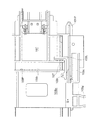
まず、本発明が適用可能な画像形成装置の一実施形態について、図1を参照して説明する。ここで、図1は本発明が適用可能なタンデム型カラー画像形成装置の概略構成図である。   First, an embodiment of an image forming apparatus to which the present invention is applicable will be described with reference to FIG. Here, FIG. 1 is a schematic configuration diagram of a tandem color image forming apparatus to which the present invention is applicable.

本実施の形態に係る画像形成装置の一例である複写機は、原稿読取装置により読み取られた原稿の画像情報、図示しないパーソナルコンピュータ等のように複写機に対して画像情報を入力する画像情報入力装置から送られてくる画像情報等が入力され、入力された画像情報に対して画像処理が行われるようになっている。   The copying machine, which is an example of the image forming apparatus according to the present embodiment, has an image information input for inputting image information to a copying machine such as an image information of a document read by a document reading device or a personal computer (not shown). Image information or the like sent from the apparatus is input, and image processing is performed on the input image information.

図1において、1は電子写真方式のタンデム型のデジタルカラー型複写機の本体を示すものであり、本体1の上部に、原稿2を一枚ずつ分離した状態で自動的に搬送する自動原稿搬送装置3と、自動原稿搬送装置3によって搬送される原稿2の画像を読み取る原稿読取装置4が配設されている。この原稿読取装置4は、プラテンガラス5上の原稿2を光源6によって走査し、原稿2からの反射光像を、フルレートミラー7及びハーフレートミラー8,9及び結像レンズ10からなる縮小光学系を介してCCD等からなる画像読取素子11上に露光して、この画像読取素子11によって原稿2の反射光像を予め定められたドット密度(例えば、16ドット/mm)で読み取るようになっている。   In FIG. 1, reference numeral 1 denotes a main body of an electrophotographic tandem type digital color copying machine, and automatic document transport for automatically transporting documents 2 one by one on the top of the body 1. An apparatus 3 and a document reading device 4 that reads an image of the document 2 conveyed by the automatic document conveying device 3 are provided. The document reading device 4 scans a document 2 on a platen glass 5 with a light source 6, and converts a reflected light image from the document 2 into a reduction optical system including a full rate mirror 7, half rate mirrors 8 and 9, and an imaging lens 10. The image reading element 11 made of a CCD or the like is exposed to light, and the reflected light image of the document 2 is read by the image reading element 11 at a predetermined dot density (for example, 16 dots / mm). Yes.

原稿読取装置4によって読み取られた原稿2の色材反射光像は、例えば、赤(R)、緑(G)、青(B)(各8bit)の3色の原稿反射率データとして画像処理装置12に送られ、この画像処理装置12では、原稿2の反射率データに対して、シェーデイング補正、位置ズレ補正、明度/色空間変換、ガンマ補正、枠消し、色/移動編集等の画像処理が施される。また、画像処理装置12は、パーソナルコンピュータ等から送られてくる画像データに対しても、画像処理を行うようになっている。   The color material reflected light image of the document 2 read by the document reading device 4 is, for example, an image processing device as document reflectance data of three colors of red (R), green (G), and blue (B) (8 bits each). In this image processing apparatus 12, image processing such as shading correction, position shift correction, brightness / color space conversion, gamma correction, frame deletion, color / moving editing, etc. is performed on the reflectance data of the document 2. Is given. The image processing apparatus 12 also performs image processing on image data sent from a personal computer or the like.

そして、上記の如く画像処理装置12で画像処理が施された画像データは、同じく画像処理装置12によって、イエロー(Y)、マゼンタ(M)、シアン(C)、黒(K)(各8ビット)の4色の階調データに変換され、次に述べるように、イエロー(Y)、マゼンタ(M)、シアン(C)、黒(K)の各色の画像形成ユニット13Y,13M,13C,13Kの走査光学系14に送られ、露光手段である走査光学系14では、各色画像形成ユニット13Y,13M,13C,13Kに対応した階調データに応じてレーザ光LBによる画像露光が行われる。   The image data subjected to the image processing by the image processing device 12 as described above is similarly processed by the image processing device 12 to yellow (Y), magenta (M), cyan (C), black (K) (each 8 bits). ), And as described below, image forming units 13Y, 13M, 13C, and 13K for each color of yellow (Y), magenta (M), cyan (C), and black (K). In the scanning optical system 14, which is an exposure means, image exposure with the laser beam LB is performed in accordance with the gradation data corresponding to the color image forming units 13Y, 13M, 13C, and 13K.

また、本実施の形態に係る画像形成装置では、各々色の異なるトナー像を形成する複数の画像形成ユニット13Y,13M,13C,13Kを並列的に配置するとともに、この複数の画像形成ユニット13Y,13M,13C,13Kの上部にわたって、当該複数の画像形成ユニット13Y,13M,13C,13Kで形成された各色のトナー像が転写されるベルト状の中間転写体25を配置し、さらに複数の画像形成ユニット13Y,13M,13C,13Kの下方に、各画像形成ユニット13Y,13M,13C,13Kの像保持体15Y,15M,15C,15Kに画像の書き込みを行なう画像書込手段14Y,14M,14C,14Kを配置している。   In the image forming apparatus according to the present embodiment, a plurality of image forming units 13Y, 13M, 13C, and 13K that form toner images of different colors are arranged in parallel, and the plurality of image forming units 13Y, 13Y, A belt-like intermediate transfer body 25 to which the toner images of the respective colors formed by the plurality of image forming units 13Y, 13M, 13C, and 13K are transferred is disposed over the upper portions of 13M, 13C, and 13K, and further, a plurality of image formation is performed. Below the units 13Y, 13M, 13C, 13K, image writing means 14Y, 14M, 14C for writing images to the image carriers 15Y, 15M, 15C, 15K of the image forming units 13Y, 13M, 13C, 13K. 14K is arranged.

イエロー(Y)、マゼンタ(M)、シアン(C)、黒(K)の各色に対応する4つの画像形成ユニット13Y,13M,13C,13Kは、複数の張架ロールにより張架された無端状の中間転写ベルト25の進行方向に沿って水平方向に一定の間隔をおいて並列的に配置されており、それぞれイエロー色、マゼンタ色、シアン色及び黒色のトナー像が予め定められたタイミングで順次形成されるように構成されている。なお、これらの各画像形成ユニット13Y,13M,13C,13Kは、以下適宜、各構成機器の符号は総称表記(例えば、感光ドラム15)とするが、例えば、使用頻度が他と比べて多い黒色に関しては例えば感光ドラム15Kを大きくすることなどがあり、全く同一であることを示すわけではない。   The four image forming units 13Y, 13M, 13C, and 13K corresponding to each color of yellow (Y), magenta (M), cyan (C), and black (K) are endlessly stretched by a plurality of stretching rolls. Are arranged in parallel in the horizontal direction along the traveling direction of the intermediate transfer belt 25, and the yellow, magenta, cyan, and black toner images are sequentially arranged at predetermined timings, respectively. It is comprised so that it may be formed. In the image forming units 13Y, 13M, 13C, and 13K, the reference numerals of the constituent devices are hereinafter collectively referred to as generic names (for example, the photosensitive drum 15). For example, black is used more frequently than others. For example, the photosensitive drum 15K may be enlarged, and it does not indicate that they are exactly the same.

各画像形成ユニット13Y,13M,13C,13Kは、大別して、予め定められた速度(例えば、200mm/sec)で回転駆動される像保持体としての感光ドラム15と、この感光ドラム15の表面を一様に帯電する帯電手段としてのコロナワイヤとグリッドとを含む帯電ユニット16と、当該感光ドラム15の表面に各感光ドラム15に対応した画像を露光して静電潜像を形成する露光手段としての走査光学系14と、感光ドラム15上に形成された静電潜像を各感光ドラム15に対応した色のトナーで現像する現像手段としての現像装置17と、感光ドラム15の表面を清掃するクリーニング手段としてのドラムクリーニング装置18等とから構成されている。なお、本実施の形態において、帯電ユニット16は被保護部材の一例であり、コロナワイヤ及びグリッドと感光ドラム15とが非接触な状態で、予め定められた電圧を印加することにより、感光ドラム15の表面を帯電し、画像形成装置1に対してコロナワイヤとグリッドとを感光ドラム15に対して独立して着脱自在に構成され、複写機本体1から個別に交換を可能としたものを指す。   The image forming units 13Y, 13M, 13C, and 13K are roughly divided into a photosensitive drum 15 as an image holding member that is rotationally driven at a predetermined speed (for example, 200 mm / sec), and a surface of the photosensitive drum 15. As a charging unit 16 including a corona wire and a grid as a charging means for uniformly charging, and an exposure means for forming an electrostatic latent image by exposing an image corresponding to each photosensitive drum 15 on the surface of the photosensitive drum 15. The scanning optical system 14, the developing device 17 as developing means for developing the electrostatic latent image formed on the photosensitive drum 15 with toner of a color corresponding to each photosensitive drum 15, and the surface of the photosensitive drum 15 are cleaned. It comprises a drum cleaning device 18 as a cleaning means. In the present embodiment, the charging unit 16 is an example of a member to be protected. By applying a predetermined voltage in a state where the corona wires and the grid and the photosensitive drum 15 are not in contact with each other, the photosensitive drum 15 is applied. The image forming apparatus 1 is configured such that a corona wire and a grid are detachably attached to the photosensitive drum 15 independently of the image forming apparatus 1 and can be individually replaced from the copying machine main body 1.

本実施の形態において、走査光学系14は、4つの画像形成ユニット13Y,13M,13C,13Kに共通に構成されており、図示しない4つの半導体レーザを各色の階調データに応じて変調して、これらの半導体レーザからレーザ光LB−Y,LB−M,LB−C,LB−Kを階調データに応じて照射するように構成されている。なお、上記走査光学系14は、複数の画像形成ユニット毎に個別に構成してもよい。上記半導体レーザから出射されたレーザ光LB−Y,LB−M,LB−C,LB−Kは、図示しないf−θレンズを介してポリゴンミラー19に照射され、このポリゴンミラー19によって偏向走査される。上記ポリゴンミラー19によって偏向走査されたレーザ光LB−Y,LB−M,LB−C,LB−Kは、図示しない結像レンズ及び複数枚のミラーを介して、感光ドラム15上の露光ポイントに、斜め下方から走査露光される。   In the present embodiment, the scanning optical system 14 is configured in common to the four image forming units 13Y, 13M, 13C, and 13K, and modulates four semiconductor lasers (not shown) according to the gradation data of each color. These semiconductor lasers are configured to emit laser beams LB-Y, LB-M, LB-C, and LB-K in accordance with gradation data. The scanning optical system 14 may be individually configured for each of a plurality of image forming units. The laser beams LB-Y, LB-M, LB-C, and LB-K emitted from the semiconductor laser are irradiated to the polygon mirror 19 through an f-θ lens (not shown), and are deflected and scanned by the polygon mirror 19. The The laser beams LB-Y, LB-M, LB-C, and LB-K deflected and scanned by the polygon mirror 19 pass through an imaging lens (not shown) and a plurality of mirrors to an exposure point on the photosensitive drum 15. Then, scanning exposure is performed obliquely from below.

本実施の形態において、上記走査光学系14は、その周囲が直方体状のフレーム20によって密閉されていると共に、当該フレーム20の上部には、4本のレーザ光LB−Y,LB−M,LB−C,LB−Kを、各画像形成ユニット13Y,13M,13C,13Kの感光ドラム15上に露光するため、シールド部材としての透明なガラス製のウインドウ21Y,21M,21C,21Kが設けられている。   In the present embodiment, the scanning optical system 14 is hermetically sealed by a rectangular parallelepiped frame 20, and four laser beams LB-Y, LB-M, and LB are provided above the frame 20. In order to expose -C and LB-K onto the photosensitive drums 15 of the image forming units 13Y, 13M, 13C, and 13K, transparent glass windows 21Y, 21M, 21C, and 21K are provided as shield members. Yes.

上記画像処理装置12からは、イエロー(Y)、マゼンタ(M)、シアン(C)、黒(K)の各色の画像形成ユニット13Y,13M,13C,13Kに共通して設けられた走査光学系14に、各色の画像データが順次出力され、この走査光学系14から画像データに応じて出射されたレーザ光LB−Y,LB−M,LB−C,LB−Kは、対応する感光ドラム15の表面に走査露光され、静電潜像が形成される。上記感光ドラム15上に形成された静電潜像は、現像装置17によって、それぞれイエロー(Y)、マゼンタ(M)、シアン(C)、黒(K)の各色のトナー像として現像(可視像化)される。   From the image processing device 12, a scanning optical system provided in common for the image forming units 13Y, 13M, 13C, and 13K for each color of yellow (Y), magenta (M), cyan (C), and black (K). 14, the image data of each color is sequentially output, and the laser beams LB-Y, LB-M, LB-C, and LB-K emitted from the scanning optical system 14 in accordance with the image data correspond to the corresponding photosensitive drums 15. The surface is exposed to scanning to form an electrostatic latent image. The electrostatic latent image formed on the photosensitive drum 15 is developed (visible) as a toner image of each color of yellow (Y), magenta (M), cyan (C), and black (K) by the developing device 17. Imaged).

上記各画像形成ユニット13Y,13M,13C,13Kの感光ドラム15上に、順次形成されたイエロー(Y)、マゼンタ(M)、シアン(C)、黒(K)の各色のトナー像は、各画像形成ユニット13Y,13M,13C,13Kの上方にわたって配置された転写ユニット22の中間転写ベルト(ベルト状の中間転写体)25上に、4つの一次転写ロール26Y,26M,26C,26Kによって順次多重に転写される。これらの一次転写ロール26Y,26M,26C,26Kは、各画像形成ユニット13Y,13M,13C,13Kの感光ドラム15に対応した中間転写ベルト25の裏面側に配設されている。ここで、各一次転写ロール26Y,26M,26C,26Kは、所望の体積抵抗値に調整されており、これらの一次転写ロール26Y,26M,26C,26Kには、不図示の転写バイアス電源が接続されており、トナー極性とは逆極性(本実施の形態では正極性)の転写バイアスが予め定められたタイミングで印加されるようになっている。   The yellow (Y), magenta (M), cyan (C), and black (K) toner images sequentially formed on the photosensitive drums 15 of the image forming units 13Y, 13M, 13C, and 13K are as follows. On the intermediate transfer belt (belt-shaped intermediate transfer member) 25 of the transfer unit 22 disposed over the image forming units 13Y, 13M, 13C, and 13K, the images are sequentially multiplexed by the four primary transfer rolls 26Y, 26M, 26C, and 26K. Is transcribed. These primary transfer rolls 26Y, 26M, 26C, and 26K are disposed on the back side of the intermediate transfer belt 25 corresponding to the photosensitive drums 15 of the image forming units 13Y, 13M, 13C, and 13K. Here, each primary transfer roll 26Y, 26M, 26C, and 26K is adjusted to a desired volume resistance value, and a transfer bias power source (not shown) is connected to these primary transfer rolls 26Y, 26M, 26C, and 26K. Thus, a transfer bias having a polarity opposite to the toner polarity (positive polarity in the present embodiment) is applied at a predetermined timing.

また、上記中間転写ベルト25は、ドライブロール27と、テンションロール24と、バックアップロール28との間に一定のテンションで掛け回されており、図示しない定速性に優れた専用の駆動モーターによって回転駆動されるドライブロール27により、矢印方向に循環するように駆動されるようになっている。上記中間転写ベルト25は、例えば、チャージアップを起こさないべルト素材(ゴムまたは樹脂)にて抵抗調整されたものが使用されている。   The intermediate transfer belt 25 is wound around the drive roll 27, the tension roll 24, and the backup roll 28 with a constant tension, and is rotated by a dedicated drive motor with excellent constant speed (not shown). The drive roll 27 is driven so as to circulate in the direction of the arrow. As the intermediate transfer belt 25, for example, a belt whose resistance is adjusted with a belt material (rubber or resin) that does not cause charge-up is used.

上記中間転写ベルト25上に多重に転写されたイエロー(Y)、マゼンタ(M)、シアン(C)、黒(K)の各色のトナー像は、当該中間転写ベルト25の側面に配置されたバックアップロール28に圧接する二次転写ロール29によって、圧接力及び静電吸引力により記録媒体としての記録用紙P上に二次転写され、これら各色のトナー像が転写された記録用紙Pは、上方に位置する定着装置30へと搬送される。上記二次転写ロール29は、バックアップロール28の側方に圧接しており、鉛直方向の下方から上方に搬送される記録用紙P上に、各色のトナー像を二次転写するようになっている。   The yellow (Y), magenta (M), cyan (C), and black (K) toner images transferred onto the intermediate transfer belt 25 in multiple layers are backed up on the side of the intermediate transfer belt 25. The recording paper P, which is secondarily transferred onto the recording paper P as a recording medium by the secondary transfer roll 29 in pressure contact with the roll 28 and onto which the toner images of these colors are transferred, is directed upward. It is conveyed to the fixing device 30 located. The secondary transfer roll 29 is in pressure contact with the side of the backup roll 28, and secondarily transfers the toner images of the respective colors onto the recording paper P that is conveyed upward from below in the vertical direction. .

上記記録用紙Pは、装置本体1の内部に配設された給紙カセット34から、ナジャーロール35及び用紙分離搬送用のフィードロール36により、1枚ずつ分離された状態で用紙搬送路37に設けられたレジストロール38まで一旦搬送され停止される。上記給紙カセット34から供給された記録用紙Pは、形成された画像に対応したタイミングで回転駆動されるレジストロール38によって中間転写ベルト25の二次転写位置へ送出される。   The recording paper P is separated one by one from a paper feed cassette 34 disposed inside the apparatus main body 1 by a nudger roll 35 and a feed roll 36 for paper separation and conveyance to a paper conveyance path 37. It is once conveyed to the provided registration roll 38 and stopped. The recording paper P supplied from the paper feed cassette 34 is sent to the secondary transfer position of the intermediate transfer belt 25 by a registration roll 38 that is rotationally driven at a timing corresponding to the formed image.

レジストロール38には、記録用紙Pがレジストロ−ラ対3に接する時に発生し、レジストロ−ル38表面に付着した紙粉を除去する紙粉除去用のブレード38aが接触して設けられている。また、ブレード38aは、ブレード38aによってレジストロ−ラ38の表面から掻き落した紙粉を回収する紙粉回収容器38bと共に一体的に装置本体に対して着脱可能に構成されている。   The registration roll 38 is provided with a blade 38a for removing paper dust that is generated when the recording paper P comes into contact with the registration roller pair 3 and removes paper dust attached to the surface of the registration roll 38. The blade 38a is configured to be detachable from the apparatus main body together with a paper dust collecting container 38b for collecting the paper dust scraped off from the surface of the registration roller 38 by the blade 38a.

なお、本実施の形態に係るデジタルカラー画像形成装置において、フルカラー等の両面コピーをとる場合には、片面に画像が定着された記録用紙Pを、排出ロール32によって排出トレイ33上にそのまま排出せずに、図示しない切替ゲートによって搬送方向を切り替え、用紙搬送用のローラ対39を介して両面用搬送ユニット40へと搬送する。そして、この両面用搬送ユニット40では、搬送径路41に沿って設けられた図示しない搬送用ローラ対により、記録用紙Pの表裏が反転された状態で、再度レジストロール38へと搬送され、今度は、当該記録用紙Pの裏面に画像が転写・定着された後、排出トレイ33上に排出される。なお、図中,44Y,44M,44C,44Kは、イエロー(Y)、マゼンタ(M)、シアン(C)、黒(K)の各色の現像装置17に、対応した色のトナーを供給するトナーカートリッジをそれぞれ示している。   In the digital color image forming apparatus according to the present embodiment, when double-sided copying such as full color is performed, the recording paper P with the image fixed on one side is directly discharged onto the discharge tray 33 by the discharge roll 32. Instead, the conveyance direction is switched by a switching gate (not shown), and the sheet is conveyed to the duplex conveyance unit 40 via the sheet conveyance roller pair 39. In the double-sided conveyance unit 40, the recording paper P is conveyed again to the registration roll 38 with the pair of conveyance rollers (not shown) provided along the conveyance path 41 turned upside down. Then, after the image is transferred and fixed on the back surface of the recording paper P, it is discharged onto the discharge tray 33. In the figure, 44Y, 44M, 44C, and 44K are toners that supply toners of corresponding colors to the developing devices 17 of the respective colors of yellow (Y), magenta (M), cyan (C), and black (K). Each cartridge is shown.

本実施の形態において、上記各色の画像形成ユニット13Y、13M,13C、13Kは、上述したように、感光ドラム15を備えており、これらの感光ドラム15の表面は、スコロトロン16によって一様に帯電される。その後、上記感光ドラム15の表面は、走査光学系14から画像データに応じて出射される画像形成用のレーザ光LBが走査露光されて、各色に対応した静電潜像が形成される。上記感光ドラム15上に走査露光されるレーザ光LBは、当該感光ドラム15の直下よりやや右側寄りの斜め下方から露光されるように設定されている。上記感光ドラム15上に形成された静電潜像は、各画像形成ユニット13Y、13M、13C、13Kの現像装置17の現像ロールによってそれぞれイエロー色、マゼンタ色、シアン色、黒色の各色のトナーにより現像されて可視トナー像となり、これらの可視トナー像は、一次転写ロール26の帯電によって中間転写ベルト25上に順次多重に転写される。   In the present embodiment, the image forming units 13Y, 13M, 13C, and 13K for the respective colors include the photosensitive drums 15 as described above, and the surfaces of these photosensitive drums 15 are uniformly charged by the scorotron 16. Is done. Thereafter, the surface of the photosensitive drum 15 is scanned and exposed to an image forming laser beam LB emitted from the scanning optical system 14 according to the image data, and an electrostatic latent image corresponding to each color is formed. The laser beam LB that is scanned and exposed on the photosensitive drum 15 is set so as to be exposed from an obliquely lower side slightly to the right side from directly below the photosensitive drum 15. The electrostatic latent image formed on the photosensitive drum 15 is made up of yellow, magenta, cyan, and black toners by the developing rolls of the developing devices 17 of the image forming units 13Y, 13M, 13C, and 13K. The toner images are developed into visible toner images, and these visible toner images are sequentially transferred in multiple onto the intermediate transfer belt 25 by the charging of the primary transfer roll 26.

なお、トナー像の転写工程が終了した後の感光ドラム15の表面は、ドラムクリーニング装置18によって残留トナー等が除去されて、次の画像形成プロセスに備える。上記ドラムクリーニング装置18は、不図示のクリーニングブレードによって感光ドラム15上の残留トナー等を除去するようになっている。また、トナー像の転写工程が終了した後の中間転写ベルト25の表面は、クリーニングブラシ43a及びクリーニングブレード43bを備えたベルトクリーニング装置43によって残留トナーや紙粉等が除去されて、次の画像形成プロセスに備える。   In addition, the toner remaining on the surface of the photosensitive drum 15 after the toner image transfer step is removed by the drum cleaning device 18 is prepared for the next image forming process. The drum cleaning device 18 is configured to remove residual toner and the like on the photosensitive drum 15 with a cleaning blade (not shown). Further, after the toner image transfer process is completed, the surface of the intermediate transfer belt 25 is freed of residual toner, paper dust, and the like by a belt cleaning device 43 including a cleaning brush 43a and a cleaning blade 43b, and the next image formation. Prepare for the process.

このような中間転写ベルト25等が装備された画像形成装置1では、感光ドラム15上のトナー像が一次転写位置で中間転写ベルト25に静電的に一次転写される。この際、単色画像を形成する場合には、中間転写ベルト25に一次転写されたトナー像が二次転写位置で直ちに記録用紙Pへ静電的に二次転写される。これに対し、カラー画像を形成する場合には、複数色のトナー像が中間転写ベルト25に順次一次転写されて重ね合わされた後に、二次転写位置で記録用紙Pに一括して二次転写される。   In the image forming apparatus 1 equipped with such an intermediate transfer belt 25 or the like, the toner image on the photosensitive drum 15 is electrostatically primarily transferred to the intermediate transfer belt 25 at the primary transfer position. At this time, in the case of forming a single color image, the toner image primarily transferred to the intermediate transfer belt 25 is secondarily electrostatically transferred onto the recording paper P immediately at the secondary transfer position. On the other hand, when forming a color image, a plurality of color toner images are sequentially primary-transferred and superimposed on the intermediate transfer belt 25, and then secondary-transferred collectively onto the recording paper P at the secondary transfer position. The

そして、中間転写ベルト25上から各色のトナー像が二次転写された記録用紙Pは、中間転写ベルト25から分離された後、二次転写手段の下流側に配設された定着装置30へと搬送され、この定着装置30によって熱及び圧力でトナー像が記録用紙P上に定着されるようになっている。定着後の記録用紙Pは、排出ロール32を介して排出トレイ33上に排出される。このような一連の画像形成プロセスを経て単色画像又はカラー画像の形成が行われる。   Then, the recording paper P on which the toner images of the respective colors are secondarily transferred from the intermediate transfer belt 25 is separated from the intermediate transfer belt 25 and then to the fixing device 30 disposed on the downstream side of the secondary transfer unit. The toner image is conveyed and fixed on the recording paper P by heat and pressure by the fixing device 30. The recording sheet P after fixing is discharged onto the discharge tray 33 via the discharge roll 32. A monochromatic image or a color image is formed through such a series of image forming processes.

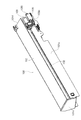
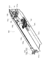
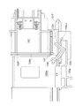
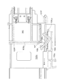
次に、本実施の形態に係り、保護部材の一例である帯電ユニット16の帯電カバー100の構成について、図2〜図10を参照して以下に説明する。ここで、図2は、本実施の形態に係る帯電カバー100の構成を説明するための装置上方から見た斜視図であり、図3及び図4は、帯電カバー100の構成を説明するための装置下方(底部側)から見た斜視図である。また、図5及び図6は、保護筐体固定部材の構成を説明するための模式的拡大図であり、図7〜図10は、操作レバー103による着脱操作を説明するための模式的拡大図である。   Next, a configuration of the charging cover 100 of the charging unit 16 that is an example of the protection member according to the present embodiment will be described below with reference to FIGS. Here, FIG. 2 is a perspective view seen from above the apparatus for explaining the configuration of the charging cover 100 according to the present embodiment, and FIGS. 3 and 4 are diagrams for explaining the configuration of the charging cover 100. It is the perspective view seen from the apparatus downward (bottom part side). 5 and 6 are schematic enlarged views for explaining the configuration of the protective housing fixing member, and FIGS. 7 to 10 are schematic enlarged views for explaining the attaching / detaching operation by the operation lever 103. FIG. It is.

なお便宜上、以下の説明においては、交換可能に形成された被保護部材の一例として、帯電ユニット16を例にとって説明する。ここで、本実施の形態における帯電ユニット16は、その長手方向一端部(帯電ユニット16を複写機本体1に装着した際に位置決め用シャーシ200から突出する部分)に、鍔部16Tを有して断面略T字状に形成された樹脂製の端部カバー16Cを備えている(図7〜図10参照)と共に、かかる帯電ユニット16を装着方向に押し込むことにより、その詳細を後述する、複写機本体1に設けられた係合部材と弾性的に係合して固定されるようになっている。   For convenience, in the following description, the charging unit 16 will be described as an example of a member to be protected that can be replaced. Here, the charging unit 16 in the present embodiment has a flange portion 16T at one end in the longitudinal direction (a portion protruding from the positioning chassis 200 when the charging unit 16 is mounted on the copying machine main body 1). A copying machine having a resin end cover 16C having a substantially T-shaped cross section (see FIGS. 7 to 10) and pushing the charging unit 16 in the mounting direction, the details of which will be described later. The engagement member provided in the main body 1 is elastically engaged and fixed.

本実施の形態に係る帯電ユニット16の帯電カバー100は、図2に示すように、複写機本体1とは別体で設けられ、保護壁の一例である側壁101s、上壁101u,底壁101bによって箱状(中空で略直方体の形状)に形成され、その内部に帯電ユニット16を収容し保護する保護部材の一例である保護筐体101と、この保護筐体101の側壁101sの上部に長手方向に渡って設けられたスリット102と、このスリット102に沿ってスライド可能に取りつけられ、帯電ユニット16を長手方向(着脱方向)に沿って移動するときに操作する操作部の一例である操作レバー103と、保護筐体101の先端側(画像形成装置1側)であって操作レバー103の下方に設けられ、保護筐体101の画像形成装置1への固定を可能とする保護筐体固定部材としての固定爪105と、保護筐体101の上壁101uの先端側(画像形成装置1側)に設けられて、筐体内に収容された帯電ユニット16が先端側から飛び出すのを塞き止めるように位置を規制する第1規制部材の一例である塞止部材109Lと、帯電ユニット16を複写機本体1に装着するときに装着方向に沿って案内する案内部の一例であるガイドレール101g(図3参照)等を備えている。   As shown in FIG. 2, the charging cover 100 of the charging unit 16 according to the present embodiment is provided separately from the copying machine main body 1, and includes a side wall 101s, an upper wall 101u, and a bottom wall 101b, which are examples of protective walls. Are formed in a box shape (hollow and substantially rectangular parallelepiped shape), and a protective case 101 which is an example of a protective member that houses and protects the charging unit 16 therein, and a longitudinally upper portion of the side wall 101s of the protective case 101 A slit 102 provided across the direction, and an operation lever that is slidably mounted along the slit 102 and is an example of an operation unit that is operated when the charging unit 16 is moved along the longitudinal direction (detachment direction). 103, provided on the front end side (image forming apparatus 1 side) of the protective casing 101 and below the operation lever 103, so that the protective casing 101 can be fixed to the image forming apparatus 1. A fixing claw 105 serving as a protective casing fixing member and a charging unit 16 provided in the front end side (image forming apparatus 1 side) of the upper wall 101u of the protective casing 101 and protruding from the front end side. An example of a blocking member 109L, which is an example of a first regulating member that regulates the position so as to block the image, and a guide unit that guides the charging unit 16 along the mounting direction when the charging unit 16 is mounted on the copying machine main body 1. A guide rail 101g (see FIG. 3) and the like are provided.

保護筐体101は、図2〜図4に示すように、その長手方向一端部側(画像形成装置1側)が開口端101fとなっていると共に、他端部側が閉鎖端101eとなっている。また、保護筐体101の開口端101fには、操作レバー103の移動軌跡の下方に帯電カバー100を複写機本体1に対して固定するための固定爪105が設けられている。この固定爪105は、断面略く字状のレバー部材であり、その先端部に幅方向(長手方向と直交する方向)内側に付勢されたロック爪105tを有すると共に、その基端側にロック爪105tによる固定状態を解除するロック解除部105bを有し、かかるロック解除部105bを幅方向内側(図5の矢印方向)に移動することにより、先端のロック爪105tが付勢力に抗して外側に開くようになっている。   As shown in FIGS. 2 to 4, the protective casing 101 has one end side in the longitudinal direction (image forming apparatus 1 side) as an open end 101 f and the other end side as a closed end 101 e. . A fixing claw 105 for fixing the charging cover 100 to the copying machine main body 1 is provided at the opening end 101 f of the protective housing 101 below the movement locus of the operation lever 103. The fixed claw 105 is a lever member having a substantially rectangular cross section. The fixed claw 105 has a lock claw 105t biased inward in the width direction (direction orthogonal to the longitudinal direction) at the distal end thereof, and is locked on the proximal end side. It has a lock release part 105b that releases the fixed state by the claw 105t, and by moving the lock release part 105b inward in the width direction (in the direction of the arrow in FIG. 5), the lock claw 105t at the tip resists the urging force. It opens to the outside.

さらに、図5及び図6に拡大して示すように、保護筐体101の開口端101fには、位置決め用に画像形成装置1側に突出して形成された複数の突起片101p1〜101p3が設けられており、これらの突起片101p1〜101p3を画像形成装置1の位置決め用シャーシ200に設けられた対応する位置決め孔200h1〜200h3に挿入することにより、保護筐体101の位置決めを行うと共に、保護筐体101の先端縁部が画像形成装置1の位置決め用シャーシ200に突き当たった時点で、上記固定爪105先端のロック爪105tが位置決め用シャーシ200側に設けられたロック孔200h4と係合し(図5参照)、これにより、保護筐体101が画像形成装置1に対して固定されるようになっている。また、上記ロック解除部105bを矢印方向(幅方向内側)に移動することにより、ロック爪105tによる固定状態が解除され(図6参照)、保護筐体101を画像形成装置1から容易に引き抜く(取り外す)ことが可能となる。 5 and 6, a plurality of protruding pieces 101p 1 to 101p 3 are formed at the opening end 101f of the protective housing 101 so as to protrude toward the image forming apparatus 1 for positioning. The protrusions 101p 1 to 101p 3 are provided and inserted into corresponding positioning holes 200h 1 to 200h 3 provided in the positioning chassis 200 of the image forming apparatus 1, thereby positioning the protective casing 101. In addition, when the leading edge of the protective housing 101 abuts against the positioning chassis 200 of the image forming apparatus 1, the locking claw 105t at the distal end of the fixed claw 105 is provided with a locking hole 200h 4 provided on the positioning chassis 200 side. (See FIG. 5), so that the protective casing 101 is fixed to the image forming apparatus 1. Further, by moving the lock release portion 105b in the direction of the arrow (inward in the width direction), the fixed state by the lock claw 105t is released (see FIG. 6), and the protective housing 101 is easily pulled out from the image forming apparatus 1 ( Can be removed).

ここで、上述した位置決め用の突起片101pや、対応する位置決め孔200h等の設置数や設置位置あるいは形状等は、適宜任意に設定することができる。   Here, the number of installations, installation positions, shapes, and the like of the positioning protrusions 101p described above and the corresponding positioning holes 200h can be arbitrarily set as appropriate.

さらに、図3及び図4に最も良く示されるように、保護筐体101の底部には、帯電ユニット16の画像形成装置1に対する固定状態を解除する第2解除部材の一例としての板状の固定解除部材107が、保護筐体101の底壁101bに対して回転移動可能なように取り付けられている。   Further, as best shown in FIGS. 3 and 4, a plate-like fixing as an example of a second releasing member that releases the fixing state of the charging unit 16 with respect to the image forming apparatus 1 is provided at the bottom of the protective housing 101. The release member 107 is attached so as to be rotatable with respect to the bottom wall 101 b of the protective housing 101.

この固定解除部材107は、その先端に断面略コ字状の固定解除部107tを有して、回転支点107rを中心に回転可能に形成されていると共に、不図示の弾性部材により底壁101b側に付勢されており、図3に示すような収納状態と、図4に示すような固定解除状態とのいずれかに設定可能となっている。   The fixing release member 107 has a fixing release portion 107t having a substantially U-shaped cross section at the tip, is formed to be rotatable around a rotation fulcrum 107r, and is formed on the bottom wall 101b side by an elastic member (not shown). And can be set to either a storage state as shown in FIG. 3 or a fixed release state as shown in FIG.

そして、図3に示す収納状態においては、保護筐体101が複写機本体1に対して着脱可能となるように、保護筐体101の底部空間内に底壁101bに沿って収容されていると共に、図4に示す固定解除状態においては、その先端の固定解除部107tが保護筐体101の底壁101bに沿って、保護筐体101の先端から突出するようになっている。なお、上記固定解除部材107の動作や機能の詳細については後述する。   In the storage state shown in FIG. 3, the protective housing 101 is housed in the bottom space of the protective housing 101 along the bottom wall 101b so that the protective housing 101 can be attached to and detached from the copying machine main body 1. In the unlocked state shown in FIG. 4, the unlocking portion 107 t at the tip protrudes from the tip of the protective housing 101 along the bottom wall 101 b of the protective housing 101. The details of the operation and function of the fixing release member 107 will be described later.

本実施の形態において、操作レバー103の移動を可能とするスリット102は、図3に最も良く示されるように、保護筐体101の側壁101sの上部に渡って着脱方向に沿って直線状に形成されており、操作レバー103の円滑なスライド動作を可能とする軌道部102gと、この軌道部102gの先端(画像形成装置1側の端部)にて、かかる軌道部102gよりも幅広に形成された略方形の切り欠き部102sとを有している。   In the present embodiment, the slit 102 that allows the operation lever 103 to move is formed in a straight line along the attaching / detaching direction over the upper portion of the side wall 101s of the protective housing 101, as best shown in FIG. The track portion 102g that enables a smooth sliding operation of the operation lever 103 and the tip of the track portion 102g (the end portion on the image forming apparatus 1 side) are formed wider than the track portion 102g. And a substantially rectangular notch 102s.

操作レバー103は、その外部(保護筐体101の外表面から露出している部分)に、スリット102面と直交する方向に突出した把手部103gと、上記スリット102の切り欠き部102sを覆うように形成されたカバー部103cとを有している。   The operation lever 103 covers the handle portion 103g protruding in the direction orthogonal to the surface of the slit 102 and the notch portion 102s of the slit 102 on the outside (the portion exposed from the outer surface of the protective housing 101). And a cover portion 103c formed on the surface.

一方、操作レバー103の内部(保護筐体101の内側)には、図7〜図10に示すように、帯電ユニット16の端部カバー16Cの端面と対向する対向面103b1を有する押出部の一例であるブロック状の押出ブロック103bが把手部103gと一体に形成されており、さらに、この押出ブロック103bの上面103b0先端のスリット102側端部には、水平断面が略L字状に形成されたフック部材103Lがスリット102に対応する位置(高さ)に回転自在に取り付けられている。なお、本実施の形態において、上記押出ブロック103bの対向面103b1には、さらに、その表面が球状の突起部103pが設けられており、これにより、操作レバー103の姿勢が傾いた場合でも、帯電ユニット16の端部カバー16Cとの安定した接触を可能としている。 On the other hand, inside the operation lever 103 (inside the protective housing 101), as shown in FIGS. 7 to 10, an extrusion portion having a facing surface 103b 1 facing the end surface of the end cover 16C of the charging unit 16 is provided. a is block-shaped extrusion block 103b example is formed integrally with the grip portion 103 g, furthermore, the slit 102 side end portion of the upper surface 103b 0 tip of the extrusion block 103b, forming horizontal cross section in a substantially L shape The hook member 103 </ b> L is rotatably attached to a position (height) corresponding to the slit 102. In the present embodiment, the opposing surface 103b 1 of the extrusion block 103b is further provided with a spherical protrusion 103p on the surface, so that even when the operation lever 103 is tilted, Stable contact with the end cover 16C of the charging unit 16 is possible.

本実施の形態において、上記フック部材103Lは、押出ブロック103bの上面103b0のスリット102側先端部に設けられた回転支点103rにその一端部が接続されて回転自在に形成されていると共に、他端部が帯電ユニット16の鍔部16Tと対向するように屈曲形成された爪部103L0を形成しており、不図示のバネ等により、定常状態において外側(スリット102側)に回転するように付勢されている。また、フック部材103Lの厚さは、軌道部102gの幅(間隙)よりも広く、かつ、切り欠き部102sの幅よりも狭く設定されている。 In this embodiment, the hook member 103L has its one end portion is rotatably formed is connected to the rotating fulcrum 103r provided on the slit 102 side tip portion of the upper surface 103b 0 extrusion block 103b, other end forms a pawl portion 103L 0 which is bent so as to face the flange portion 16T of the charging unit 16, by a spring (not shown) or the like, so as to rotate outward (slit 102 side) in a steady state It is energized. Further, the thickness of the hook member 103L is set wider than the width (gap) of the track portion 102g and narrower than the width of the notch portion 102s.

このように構成した操作レバー103によれば、例えば図7に示すように、操作者が外部に突出した把手部103gを装着方向(矢印A方向)に移動させることにより、押出ブロック103bを介して保護筐体101内部に収容された帯電ユニット16をガイドレール101gに沿って装着方向に押し込む(移動させる)ことができる。なおこの際、操作レバー103が軌道部102g上を移動している間は、フック部材103Lがスリット102の内面と接触し、かかるフック部材103Lは、スリット102の外部に突出することができない(図7参照)ので、その先端の爪部103L0が帯電ユニット16の着脱方向の移動に対するストッパの機能を担って帯電ユニット16が装置本体から外れないように保持する。また、本実施の形態における操作レバー103は、帯電ユニット16が着脱方向に移動した際に帯電ユニット16の位置を規制する機能を兼用している。そして、操作レバー103をさらに装着方向(矢印A方向)にスライドさせると、フック部材103Lがスリット102の切り欠き部102sに到達した際に、当該フック部材103Lは付勢力によりスリット102の外側に突出するように回転し、カバー部103cの内面と接触して停止し、この状態を維持する(図8参照)。これにより、帯電ユニット16に対するストッパ機能が解除され、操作レバー103をさらに装着方向に移動させることにより、帯電ユニット16を円滑に画像形成装置1内に装着することができる。 According to the operation lever 103 configured as described above, for example, as shown in FIG. 7, the operator moves the handle portion 103g protruding outside in the mounting direction (the direction of the arrow A), so that the push lever 103b is interposed. The charging unit 16 accommodated in the protective housing 101 can be pushed (moved) in the mounting direction along the guide rail 101g. At this time, while the operation lever 103 is moving on the track portion 102g, the hook member 103L is in contact with the inner surface of the slit 102, and the hook member 103L cannot protrude outside the slit 102 (FIG. 7 refer), so the claw portions 103L 0 of the tip of the charging unit 16 plays the function of the stop for the movement of the detachable direction of the charging unit 16 is held so as not to be detached from the apparatus body. Further, the operation lever 103 in the present embodiment also has a function of regulating the position of the charging unit 16 when the charging unit 16 moves in the attaching / detaching direction. When the operating lever 103 is further slid in the mounting direction (the direction of arrow A), when the hook member 103L reaches the notch 102s of the slit 102, the hook member 103L protrudes to the outside of the slit 102 by the biasing force. Rotate to stop and come into contact with the inner surface of the cover portion 103c to stop and maintain this state (see FIG. 8). As a result, the stopper function for the charging unit 16 is released, and the charging unit 16 can be smoothly mounted in the image forming apparatus 1 by further moving the operation lever 103 in the mounting direction.

また操作レバー103は、帯電カバー100に引き入れる機能も兼用し、図9に示すような、操作レバー103の解除状態(スリット102の切り欠き部102sからフック部材103Lが突出してカバー部103cと接触している状態)から、操作レバー103を取り外し方向(矢印B方向)に移動させることにより、操作レバー103の移動に伴ってフック部材103Lが保護筐体101内部に引き込まれ、図10に示すような引入れ状態となる。その後、さらに操作レバー103を取り外し方向(矢印B方向)に移動させることにより、操作レバー103と帯電ユニット16の鍔部16Tとが係合(接触)した状態で帯電ユニット16をさらに矢印B方向に移動させ、かかる帯電ユニット16を容易に画像形成装置1から取り外して(引き抜いて)保護筐体101内に収容することが可能となる。   The operation lever 103 also functions to be pulled into the charging cover 100. As shown in FIG. 9, the operation lever 103 is released (the hook member 103L protrudes from the notch 102s of the slit 102 and comes into contact with the cover 103c. 10), the hook member 103L is drawn into the protective housing 101 as the operation lever 103 is moved, as shown in FIG. It becomes a withdrawal state. Thereafter, the operation lever 103 is further moved in the removal direction (arrow B direction), so that the charging unit 16 is further moved in the arrow B direction in a state where the operation lever 103 and the flange portion 16T of the charging unit 16 are engaged (contacted). The charging unit 16 can be easily removed from the image forming apparatus 1 (withdrawn) and accommodated in the protective housing 101.

次に、上述のように構成した帯電カバー100を用いた帯電ユニット16の一連の着脱操作について、図11〜図18を参照してまとめて説明する。なお、図11〜図14は、帯電ユニットの装着動作を説明するための模式図であり、図15〜図18は、帯電ユニット16の取り外し動作を説明するための模式図である。   Next, a series of operations for attaching and detaching the charging unit 16 using the charging cover 100 configured as described above will be collectively described with reference to FIGS. 11 to 14 are schematic diagrams for explaining the mounting operation of the charging unit, and FIGS. 15 to 18 are schematic diagrams for explaining the detaching operation of the charging unit 16.

ここで、本実施の形態における画像形成装置1では、例えば図11に示すように、位置決め用シャーシ200の内側に、帯電ユニット16を固定するための固定用シャーシ300がさらに設けられており、この固定用シャーシ300には、帯電ユニット16の位置決めをガイドする位置決め孔300hが形成されていると共に、帯電ユニット16をユニット側爪部16L嵌り合うように形成された第2規制部材の一例であるシャーシ側爪部300Lがその外表面に取り付けられている。一方、帯電ユニット16には、端部カバー16Cの底部に、固定用シャーシ300の位置決め孔300hと対応するように位置決めピン16pが突出形成されていると共に、シャーシ側爪部300Lと係合する、図中、略上下方向に弾性変形可能なように形成されたユニット側爪部16Lが設けられている。また、シャーシ側爪部300Lの上部には、ユニット側爪部16Lと接触した際に、当該ユニット側爪部16Lの弾性変形をガイドするテーパ面300L1が形成されている。一方、ユニット側爪部16Lには、帯電ユニット装着時の自らの弾性変形をガイドする装着テーパ面16L1がシャーシ側爪部300Lのテーパ面300L1と対向するように形成されていると共に、その反対側には、帯電ユニット取り外し時の自らの弾性変形をガイドするテーパ面16L2が前述した固定解除部材107の固定解除部107tと対向するように設けられている。 Here, in the image forming apparatus 1 according to the present embodiment, for example, as shown in FIG. 11, a fixing chassis 300 for fixing the charging unit 16 is further provided inside the positioning chassis 200. The fixing chassis 300 is formed with a positioning hole 300h for guiding the positioning of the charging unit 16, and is a chassis that is an example of a second restricting member formed so that the charging unit 16 fits the unit side claw portion 16L. The side claw portion 300L is attached to the outer surface. On the other hand, the charging unit 16 has a positioning pin 16p protruding from the bottom of the end cover 16C so as to correspond to the positioning hole 300h of the fixing chassis 300, and engages with the chassis side claw 300L. In the drawing, a unit side claw portion 16L formed so as to be elastically deformable in a substantially vertical direction is provided. In addition, a tapered surface 300L 1 that guides the elastic deformation of the unit side claw portion 16L when it contacts the unit side claw portion 16L is formed on the upper portion of the chassis side claw portion 300L. On the other hand, the unit side claw portion 16L is formed with a mounting taper surface 16L 1 that guides its own elastic deformation when the charging unit is mounted so as to face the taper surface 300L 1 of the chassis side claw portion 300L. On the opposite side, a tapered surface 16L 2 that guides its own elastic deformation when the charging unit is detached is provided so as to face the fixing release portion 107t of the fixing release member 107 described above.

まず、帯電ユニット16を画像形成装置1に装着する際には、保護筐体101の底部に設けられた固定解除部材107を収納状態に設定し(図3参照)、保護筐体101に設けられた突起片101pを複写機本体1の位置決め用シャーシ200側に設けた位置決め孔200hに挿入して、その内部に帯電ユニット16が収容された保護筐体101の位置決めを行う。そして、この状態でさらに保護筐体101を、その先端縁が位置決め用シャーシ200に突き当たるまで水平に押し込むことにより、保護筐体101の固定レバー105に設けられたロック爪105tにより保護筐体101を画像形成装置本体1に固定する。   First, when the charging unit 16 is attached to the image forming apparatus 1, the fixing release member 107 provided at the bottom of the protective casing 101 is set in the storage state (see FIG. 3), and is provided in the protective casing 101. The protruding piece 101p is inserted into a positioning hole 200h provided on the positioning chassis 200 side of the copying machine main body 1, and the protective housing 101 in which the charging unit 16 is accommodated is positioned. In this state, the protective casing 101 is further pushed horizontally until the leading edge of the protective casing 101 comes into contact with the positioning chassis 200, so that the protective casing 101 is held by the lock claw 105 t provided on the fixing lever 105 of the protective casing 101. It is fixed to the image forming apparatus main body 1.

次に、保護筐体101を複写機本体1に固定した状態で、操作レバー103を装着方向(複写機本体1方向)にスライドさせることにより、帯電ユニット16を画像形成装置1内に挿入する(図11〜図14参照)。   Next, the charging unit 16 is inserted into the image forming apparatus 1 by sliding the operation lever 103 in the mounting direction (direction of the copying machine body 1) with the protective casing 101 fixed to the copying machine body 1 ( FIG. 11 to FIG. 14).

なおこの際、帯電ユニット16の装着方向の移動に伴って、帯電ユニット16の位置決めピン16pが固定用シャーシ300の位置決め孔300hに挿入されて帯電ユニット16の位置決めがなされる(図11参照)と共に、帯電ユニット16のユニット側係合部16Lの装着テーパ面16L1と固定用シャーシ300のシャーシ側係合部300Lのテーパ面300L1とが接触し(図12参照)、シャーシ側係合部300Lのテーパ面300L1にガイドされて帯電ユニット16のユニット側係合部16Lが上方に弾性変形する(図13参照)。そして、帯電ユニット16を予め定められたストロークだけ画像形成装置1内に挿入すると、帯電ユニット16のユニット側係合部16Lが、シャーシ側係合部300Lのテーパ面300L1を乗り越えて、ユニット側係合部16Lとシャーシ側係合部300Lとが係合し、帯電ユニット16が画像形成装置1の固定用シャーシ300に装着固定される(図14参照)。 At this time, as the charging unit 16 moves in the mounting direction, the positioning pin 16p of the charging unit 16 is inserted into the positioning hole 300h of the fixing chassis 300 to position the charging unit 16 (see FIG. 11). The mounting tapered surface 16L 1 of the unit side engaging portion 16L of the charging unit 16 and the tapered surface 300L 1 of the chassis side engaging portion 300L of the fixing chassis 300 contact each other (see FIG. 12), and the chassis side engaging portion 300L. guided in the tapered surface 300L 1 in unit-side engagement portion 16L of the charging unit 16 is elastically deformed upward (see FIG. 13). When inserted into the charging unit 16 a predetermined stroke by the image forming apparatus 1, the unit-side engagement portion 16L of the charging unit 16, rides over the tapered surface 300L 1 of the chassis-side engaging portion 300L, unit side The engaging portion 16L and the chassis side engaging portion 300L are engaged, and the charging unit 16 is mounted and fixed to the fixing chassis 300 of the image forming apparatus 1 (see FIG. 14).

一方、帯電ユニット16を画像形成装置1から取り外す際には、保護筐体101の底部に設けられた固定解除部材107を固定解除状態に設定(図4参照)すると共に、予め操作レバー103を保護筐体101の開口端101f側に移動させておく。そして、保護筐体101に設けられた突起片101pを画像形成装置本体1の位置決め用シャーシ200側に設けた位置決め孔200hに挿入して保護筐体101の位置決めを行う。さらに、保護筐体101を、その先端縁が位置決め用シャーシ200に突き当たるまで水平に押し込むことにより、保護筐体101の固定レバー105に設けられたロック爪105tにより保護筐体101を画像形成装置本体1に固定する。   On the other hand, when removing the charging unit 16 from the image forming apparatus 1, the fixing release member 107 provided at the bottom of the protective housing 101 is set to the fixed release state (see FIG. 4), and the operation lever 103 is protected in advance. The housing 101 is moved to the opening end 101f side. Then, the protruding piece 101p provided on the protective casing 101 is inserted into a positioning hole 200h provided on the positioning chassis 200 side of the image forming apparatus main body 1 to position the protective casing 101. Further, the protective casing 101 is pushed in horizontally until the leading edge of the protective casing 101 comes into contact with the positioning chassis 200, so that the protective casing 101 is held by the lock claw 105 t provided on the fixing lever 105 of the protective casing 101. Fix to 1.

なお、保護筐体101を画像形成装置本体1に固定する際には、固定解除部材107が固定解除状態に設定されているので、保護筐体101の先端に固定解除部107tが突出しており、保護筐体101の装着動作(本例では、水平方向に押し込む動作)に伴って、かかる固定解除部107tが帯電ユニット16のユニット側係合部16Lの下方に潜り込む(図15参照)。この状態から、さらに保護筐体101を装着方向に押し込むと、固定解除部107tの先端がユニット側係合部16Lのテーパ面16L2と接触し(図16参照)、ユニット側係合部16Lを上方に弾性変形させる(図17参照)。そして、保護筐体101が、ロック爪105tにより画像形成装置本体1に装着固定された際には、保護筐体101から突出した固定解除部107tの先端が画像形成装置本体1に設けられたシャーシ側係合部300Lと突き当たって、ユニット側係合部16Lをその上方に十分に弾性変形させ、ユニット側係合部16Lとシャーシ側係合部300Lとの係合を解除し、この状態を維持する(図18参照)。すなわち、固定解除部材107を固定解除状態に設定し、保護筐体101を画像形成装置本体1に装着固定した状態では、帯電ユニット16と画像形成装置本体1との係合固定が解除された状態となる。 When the protective casing 101 is fixed to the image forming apparatus main body 1, the fixing release member 107 is set in the unlocked state, so that the fixing release portion 107 t protrudes from the tip of the protective casing 101. With the mounting operation of the protective housing 101 (in this example, the operation of pushing in the horizontal direction), the fixing release portion 107t sinks below the unit side engaging portion 16L of the charging unit 16 (see FIG. 15). From this state, when pushed further protective enclosure 101 in the mounting direction, the leading end of the unlocking portion 107t is in contact with the tapered surface 16L 2 unit-side engagement portion 16L (see FIG. 16), the unit-side engagement portion 16L It is elastically deformed upward (see FIG. 17). When the protective casing 101 is attached and fixed to the image forming apparatus main body 1 by the lock claw 105t, the front end of the fixing release portion 107t protruding from the protective casing 101 is the chassis provided in the image forming apparatus main body 1. The unit-side engagement portion 16L is sufficiently elastically deformed to abut against the side engagement portion 300L, and the engagement between the unit-side engagement portion 16L and the chassis-side engagement portion 300L is released, and this state is maintained. (See FIG. 18). That is, when the fixing release member 107 is set in the unlocked state and the protective housing 101 is attached and fixed to the image forming apparatus main body 1, the engagement and fixing between the charging unit 16 and the image forming apparatus main body 1 is released. It becomes.

なお、本実施の形態において、画像形成装置本体1には、帯電ユニット16を外側に押し出すための不図示の弾性部材(例えば、ばね部材)が備えられており、帯電ユニット16の画像形成装置本体1に対する固定状態が解除された場合には、帯電ユニット16を外部に押し出すようになっている。   In the present embodiment, the image forming apparatus main body 1 is provided with an unillustrated elastic member (for example, a spring member) for pushing the charging unit 16 outward, and the image forming apparatus main body of the charging unit 16 is provided. When the fixed state with respect to 1 is released, the charging unit 16 is pushed out.

また、帯電ユニット16が押し出されることで、操作レバー103が内側に移動してきたときに、引入れることが可能な位置に配置され、操作レバー103の取り外し方向への移動に伴って、帯電ユニット16を画像形成装置本体1から取り外して保護筐体101内部に引き込んで収容することが可能となる。   Further, when the operation lever 103 moves inward by being pushed out, the charging unit 16 is disposed at a position where the operation lever 103 can be pulled in, and as the operation lever 103 moves in the removal direction, the charging unit 16 is moved. Can be removed from the image forming apparatus main body 1 and retracted into the protective housing 101 for storage.

なお、本実施の形態において、位置決めされたときとは、帯電ユニット16が画像形成装置本体1に装着された装着状態を意味している。   In the present embodiment, the positioning means that the charging unit 16 is mounted on the image forming apparatus main body 1.

次に、操作レバー103を取り外し方向に移動させることにより、前述した操作レバー103にもうけられた、引入部の一例である爪部103L0により帯電ユニット16が係止され、操作レバー103の取り外し方向への移動に伴って、帯電ユニット16を複写機本体1から取り外して保護筐体101内部に引き込んで収容する。 Next, by moving the operation lever 103 in the removal direction, the charging unit 16 is locked by the claw portion 103L 0 which is an example of the drawing-in portion provided in the operation lever 103 described above, and the removal direction of the operation lever 103 With the movement to, the charging unit 16 is detached from the copying machine main body 1 and pulled into the protective housing 101 to be accommodated.

このように、本実施の形態に係る保護装置100によれば、帯電ユニット16を画像形成装置1に装着する場合、及び画像形成装置1から帯電ユニット16を取り外す場合のいずれにおいても、画像形成装置1から突出する帯電ユニット16を保護部材にて保護することができるので、帯電ユニット16を着脱操作する際に、帯電ユニット16の外表面への汚れの付着や不測の接触による傷等のダメージの発生を低減することができる。   As described above, according to the protection device 100 according to the present embodiment, both when the charging unit 16 is attached to the image forming apparatus 1 and when the charging unit 16 is detached from the image forming apparatus 1. Since the charging unit 16 protruding from 1 can be protected by a protective member, when the charging unit 16 is attached / detached, damage such as fouling on the outer surface of the charging unit 16 or unexpected damage is caused. Generation can be reduced.

なお、上述の実施の形態では、操作レバー103と一体に形成されたフック部材103Lの先端の帯電ユニット16を引入れるための部位を爪部103L0として形成したために、帯電ユニット16を取り外す際には、予め操作レバー103を開口端101f側端部に移動させておく必要があったが、本発明に係る操作部材は、上述した形態に限定されるものではなく、例えば、爪部の構成として、爪部103L2に対して帯電ユニット16が複写機本体1が配置された側から接触した時には帯電ユニット16を避けるように変形し、帯電ユニット16が逆側から接触した時にはその変形を制限することで帯電ユニット16の引き入れを可能とする関節構造を有する可動式の爪部103L2としてもよい。このような操作部材の変形例を図19〜図23を参照して以下に説明する。 In the embodiment described above, in order to form the site for draws the charging unit 16 at the tip of the hook member 103L which is integrally formed with the operating lever 103 as pawl portion 103L 0, when removing the charging unit 16 However, the operation member 103 according to the present invention is not limited to the above-described form. For example, as a configuration of the claw portion, the operation lever 103 needs to be moved to the opening end 101f side end portion. When the charging unit 16 comes into contact with the claw portion 103L 2 from the side where the copying machine main body 1 is disposed, it is deformed so as to avoid the charging unit 16, and when the charging unit 16 comes in contact from the opposite side, the deformation is limited. Thus, the movable claw portion 103L 2 having a joint structure that allows the charging unit 16 to be pulled in may be used. Modification examples of such an operation member will be described below with reference to FIGS.

本変形例に係る操作レバー103´は、先に説明した操作レバー103に比し、その爪部が爪部103L2に対して帯電ユニット16が複写機本体1が配置された側から接触した時にのみ帯電ユニット16を退避するような変形を可能とするようにフック部材103Lの構成を屈曲する関節構造としたものであり、先に説明した操作レバー103と同様な機能を有する部材には、同様な符号を付しその詳細な説明は省略する。 The operation lever 103 ′ according to the present modification is compared with the operation lever 103 described above when its claw portion comes into contact with the claw portion 103 </ b > L 2 from the side where the copying machine main body 1 is disposed. Only the structure of the hook member 103L is bent so that the charging unit 16 can be deformed so that it can be retracted. A detailed description is omitted.

本変形例に係るフック部材103L´は、図19及び図20に示すように、その一端部が第1回転支点103r1回りに回転可能となるように取り付けられた基体部103L1と、この基体部103L1の他端(先端)に設けられた第2回転支点103r2回りに回転可能に取り付けられた可動爪部103L2とを有している。基体部103L1及び可動爪部103L2の第2回転支点103r2側の端部には、それぞれストッパ面103L1s,103L2sが形成されていると共に、可動爪部103L2は、不図示のバネ等により予め定めた方向(図19における矢印方向)に回転するように付勢されている。ここで、上記ストッパ面103L1s,103L2sは、図19に示すような、可動爪部103L2が基体部103L1に対して略直交するような姿勢(以下、係止姿勢とも称する)となったときに、互いに係合するように形成されており、定常状態(可動爪部103L2に外力が加わっていない状態)では、かかる係止姿勢を維持するようになっている。一方、係止姿勢にある可動爪部103L2に対して外力Fが加わった場合には、図20に示すように、可動爪部103L2は、予め定めた一方向(本例では、図中、反時計まわり方向)にのみ屈曲可能となる。すなわち、本変形例に係る可動爪部103L2は、定常状態において、係止姿勢を維持すると共に、外力が加わった場合には、爪部103L2に対して帯電ユニット16が複写機本体1が配置された側から接触した時にのみ帯電ユニット16を退避するような変形を可能とするように構成されている。 As shown in FIGS. 19 and 20, the hook member 103 </ b> L ′ according to the present modification has a base portion 103 </ b> L 1 attached so that one end thereof can rotate around the first rotation fulcrum 103 r 1, and the base And a movable claw portion 103L 2 rotatably attached around a second rotation fulcrum 103r 2 provided at the other end (tip) of the portion 103L 1 . Stopper surfaces 103L 1 s and 103L 2 s are respectively formed at the ends of the base portion 103L 1 and the movable claw portion 103L 2 on the second rotation fulcrum 103r 2 side, and the movable claw portion 103L 2 is not shown. Is biased so as to rotate in a predetermined direction (the arrow direction in FIG. 19). Here, the stopper surfaces 103L 1 s and 103L 2 s have a posture (hereinafter, also referred to as a locking posture) in which the movable claw portion 103L 2 is substantially orthogonal to the base portion 103L 1 as shown in FIG. when becomes, thereby maintaining are formed to engage one another, in the steady state (state not subjected to any external force to the movable claw portion 103L 2), such locking position. On the other hand, when an external force F is applied to the movable claw portion 103L 2 in the locked posture, as shown in FIG. 20, the movable claw portion 103L 2 moves in a predetermined direction (in this example, in the figure). , Only in the counterclockwise direction). In other words, the movable claw portion 103L 2 according to this modification maintains a locking posture in a steady state and when the external force is applied, the charging unit 16 is connected to the copying machine main body 1 with respect to the claw portion 103L 2 . The charging unit 16 can be deformed so as to be retracted only when contacted from the side where it is disposed.

このように構成した操作レバー103´の係止部103L0の動作を図21〜図23を参照してさらに説明する。なお、操作レバー103´の基本的な動作(特に、帯電ユニット16を画像形成装置本体1に装着する際の動作)は、既に説明した操作レバー103と同様であるので、可動爪部103L2の動作を中心に説明する。 Thus the operation of the locking portion 103L 0 configuration the operating lever 103 'with reference to FIGS. 21 to 23 will be further described. The basic operation of the operating lever 103 '(in particular, the operation at the time of mounting the charging unit 16 to the image forming apparatus main body 1) is the same as the operation lever 103 already described, the movable claw portions 103L 2 The operation will be mainly described.

図21に示すように、保護筐体101を画像形成装置本体1に固定した状態で、操作レバー103により帯電ユニット16の着脱操作を行う場合(例えば、帯電ユニット16を画像形成装置本体1から取り外す操作を行う場合)に、操作レバー103´が、その係止部103L2により帯電ユニット16の鍔部16Tを係止できない位置(図21参照)にあっても、かかる操作レバー103´を開口端101f側に移動させることにより、可動爪部103L2と帯電ユニット16の鍔部16Tとが接触して、可動爪部103L2が反時計回り方向に回転して屈曲し(図22参照)、操作レバー103´をさらに移動させることにより、可動爪部103L2と鍔部16Tとの接触が解除された時点で、可動爪部103L2が付勢力により係止姿勢に復帰する(図23参照)。これにより、その後の操作レバー103´の逆方向の操作に対して、可動爪部103L2による帯電ユニット16の係止が可能となる。 As shown in FIG. 21, when the charging unit 16 is attached / detached by the operation lever 103 with the protective housing 101 fixed to the image forming apparatus main body 1 (for example, the charging unit 16 is removed from the image forming apparatus main body 1). When the operation lever 103 ′ is in a position (see FIG. 21) where the hook portion 16T of the charging unit 16 cannot be locked by the locking portion 103L 2 when the operation lever 103 ′ is operated. by moving to 101f side, in contact with the flange portion 16T of the movable claw portions 103L 2 and the charging unit 16, the movable claw portions 103L 2 bent to rotate in the counterclockwise direction (see FIG. 22), the operation by further moving the lever 103 ', when the contact between the movable claw portion 103L 2 and the flange portion 16T is released, restored to the locking posture movable claw portions 103L 2 by the biasing force Return (see FIG. 23). Thus, with respect to the reverse direction of the operation of the subsequent operating lever 103 ', it is possible to lock the charging unit 16 by the movable claw portions 103L 2.

すなわち、このように可動爪部103L2を爪部103L2に対して帯電ユニット16が複写機本体1が配置された側から接触した時には帯電ユニット16を避けるように変形可能な関節構造とした場合には、先の実施形態に比し、構造は複雑となるものの、帯電ユニット16を取り外す際に、予め操作レバー103を開口端101f側端部に移動させることなく、操作レバー103´の着脱操作が任意の位置から可能となるため、操作性、作業性の向上により一層寄与することができる。 That is, when the movable claw portion 103L 2 has a joint structure that can be deformed so as to avoid the charging unit 16 when the charging unit 16 contacts the claw portion 103L 2 from the side where the copying machine main body 1 is disposed. Although the structure is complicated as compared with the previous embodiment, when the charging unit 16 is removed, the operation lever 103 ′ is attached and detached without moving the operation lever 103 to the opening end 101 f side end in advance. Therefore, it is possible to further contribute to the improvement of operability and workability.

なお、上述した実施の形態では、本発明が適用される被保護部材の一例として帯電ユニット16を例示したが、本発明に係る帯電カバー100は、このような帯電ユニット16に限定されるものではなく、画像形成装置1に対して着脱自在に形成された部品に適用可能である。例えば、感光ドラム15をクリーニングするためのクリーニングユニットに適用してもよいし、感光ドラム15とその周辺機器(例えば、帯電器、クリーニングブレード、現像器)とを一体化した、いわゆるプロセスカートリッジのように装置本体に対して一体的に着脱可能に形成された着脱ユニット全般に対して適用してもよい。また、上述した実施の形態では、画像形成装置として電子写真方式の複写機1を例示しているが、インクジェット方式のプリンタや有版の印刷機に適用してもよい。インクジェット方式のプリンタへの適用を考える場合には、ヘッドを装置本体に対して取り外した時にはヘッドのノズル面を保護する必要があるので、ヘッドを含んで装置本体に対して着脱されるユニットに適用することができる。また、画像形成装置全般への適用を考える場合には、ブレード38aのように搬送される記録用紙Pで発生した紙粉を除去する紙粉除去部材に適用することが考えられる。上述した実施の形態では、レジストロール38に付着した紙粉を除去するブレード38aを例示したが、紙粉除去部材としては、記録用紙Pを搬送する他のロールに付着した紙粉を除去する部材や、搬送される記録用紙Pに直接接触して紙粉を除去する部材に適用できる。   In the above-described embodiment, the charging unit 16 is illustrated as an example of a protected member to which the present invention is applied. However, the charging cover 100 according to the present invention is not limited to such a charging unit 16. However, the present invention can be applied to a part that is detachably attached to the image forming apparatus 1. For example, the present invention may be applied to a cleaning unit for cleaning the photosensitive drum 15, or a so-called process cartridge in which the photosensitive drum 15 and peripheral devices (for example, a charger, a cleaning blade, and a developing device) are integrated. In addition, the present invention may be applied to all attachment / detachment units formed integrally and detachably with respect to the apparatus main body. In the above-described embodiment, the electrophotographic copying machine 1 is exemplified as the image forming apparatus. However, the image forming apparatus may be applied to an ink jet printer or a plate printer. When considering application to an ink jet printer, it is necessary to protect the nozzle surface of the head when the head is removed from the device body. can do. Further, when considering application to the entire image forming apparatus, it may be applied to a paper dust removing member that removes paper dust generated on the recording paper P conveyed like the blade 38a. In the above-described embodiment, the blade 38a that removes the paper dust attached to the resist roll 38 is exemplified. However, as the paper dust removing member, a member that removes the paper dust attached to another roll that transports the recording paper P. Alternatively, it can be applied to a member that directly contacts the recording paper P being conveyed and removes paper dust.

また、上述した実施の形態では、保護部材の一例として、その内部に収容可能とし、長手方向一端部側が開口形成されている箱状のハウジング101を例示したが、接触することで損傷が懸念される部位のみを保護する態様とすることも考えられる。例えば、帯電ユニットであればコロナワイヤやグリッドは保護し、シールドに関しては保護しない、また、プロセスカートリッジであれば感光体ドラム15の感光層に関しては保護し、周囲に配置されたクリーニング装置や現像器の樹脂の部位は保護しないなどとすることができる。   Further, in the above-described embodiment, as an example of the protective member, the box-shaped housing 101 that can be accommodated therein and whose one end side in the longitudinal direction is opened is exemplified, but there is a concern about damage due to contact. It is also conceivable that only the site to be protected is protected. For example, if the charging unit is used, the corona wires and the grid are protected and the shield is not protected. If the process cartridge is used, the photosensitive layer of the photosensitive drum 15 is protected, and a cleaning device and a developing device arranged around the protective unit. The portion of the resin may not be protected.

本発明に係る画像形成装置の一実施の形態を示す概略構成図である。1 is a schematic configuration diagram showing an embodiment of an image forming apparatus according to the present invention. 本発明に係る一実施形態の保護装置の構成を説明するための上方から見た斜視図である。It is the perspective view seen from the upper part for explaining the composition of the protection device of one embodiment concerning the present invention. 本発明に係る一実施形態の現像装置の構成を説明するための下方から見た斜視図である。It is the perspective view seen from the lower part for demonstrating the structure of the image development apparatus of one Embodiment which concerns on this invention. 本発明に係る一実施形態の現像装置の構成を説明するための下方から見た斜視図である。It is the perspective view seen from the lower part for demonstrating the structure of the image development apparatus of one Embodiment which concerns on this invention. 本発明に係る一実施形態の保護筐体固定部材の構成を説明するための模式的拡大図である。It is a typical enlarged view for demonstrating the structure of the protection housing | casing fixing member of one Embodiment which concerns on this invention. 本発明に係る一実施形態の保護筐体固定部材の構成を説明するための模式的拡大図である。It is a typical enlarged view for demonstrating the structure of the protection housing | casing fixing member of one Embodiment which concerns on this invention. 本発明に係る一実施形態の保護装置の操作レバーを装着方向に移動させた場合の、係止部の動作を説明するための模式的拡大図である。It is a typical enlarged view for demonstrating operation | movement of the latching | locking part at the time of moving the operation lever of the protection apparatus of one Embodiment which concerns on this invention to a mounting direction. 本発明に係る一実施形態の保護装置の操作レバーを装着方向に移動させた場合の、係止部の動作を説明するための模式的拡大図である。It is a typical enlarged view for demonstrating operation | movement of the latching | locking part at the time of moving the operation lever of the protection apparatus of one Embodiment which concerns on this invention to a mounting direction. 本発明に係る一実施形態の保護装置の操作レバーを取り外し方向に移動させた場合の、係止部の動作を説明するための模式的拡大図である。It is a typical enlarged view for demonstrating operation | movement of a latching | locking part at the time of moving the operation lever of the protection apparatus of one Embodiment which concerns on this invention to a removal direction. 本発明に係る一実施形態の保護装置の操作レバーを取り外し方向に移動させた場合の、係止部の動作を説明するための模式的拡大図である。It is a typical enlarged view for demonstrating operation | movement of a latching | locking part at the time of moving the operation lever of the protection apparatus of one Embodiment which concerns on this invention to a removal direction. 本発明に係る一実施形態の帯電ユニットの装着動作を説明するための模式的拡大図である。It is a typical enlarged view for demonstrating mounting | wearing operation | movement of the charging unit of one Embodiment which concerns on this invention. 本発明に係る一実施形態の帯電ユニットの装着動作を説明するための模式的拡大図である。It is a typical enlarged view for demonstrating mounting | wearing operation | movement of the charging unit of one Embodiment which concerns on this invention. 本発明に係る一実施形態の帯電ユニットの装着動作を説明するための模式的拡大図である。It is a typical enlarged view for demonstrating mounting | wearing operation | movement of the charging unit of one Embodiment which concerns on this invention. 本発明に係る一実施形態の帯電ユニットの装着動作を説明するための模式的拡大図である。It is a typical enlarged view for demonstrating mounting | wearing operation | movement of the charging unit of one Embodiment which concerns on this invention. 本発明に係る一実施形態の帯電ユニットの取り外し動作を説明するための模式的拡大図である。It is a typical enlarged view for demonstrating the removal operation | movement of the charging unit of one Embodiment which concerns on this invention. 本発明に係る一実施形態の帯電ユニットの取り外し動作を説明するための模式的拡大図である。It is a typical enlarged view for demonstrating the removal operation | movement of the charging unit of one Embodiment which concerns on this invention. 本発明に係る一実施形態の帯電ユニットの取り外し動作を説明するための模式的拡大図である。It is a typical enlarged view for demonstrating the removal operation | movement of the charging unit of one Embodiment which concerns on this invention. 本発明に係る一実施形態の帯電ユニットの取り外し動作を説明するための模式的拡大図である。It is a typical enlarged view for demonstrating the removal operation | movement of the charging unit of one Embodiment which concerns on this invention. 本発明に係る一実施形態の可動爪部の構成を説明するための模式的拡大図である。It is a typical enlarged view for explaining the composition of the movable claw part of one embodiment concerning the present invention. 本発明に係る一実施形態の可動爪部の構成を説明するための模式的拡大図である。It is a typical enlarged view for explaining the composition of the movable claw part of one embodiment concerning the present invention. 本発明に係る一実施形態の可動爪部の動作を説明するための模式的拡大図である。It is a typical enlarged view for demonstrating operation | movement of the movable nail | claw part of one Embodiment which concerns on this invention. 本発明に係る一実施形態の可動爪部の動作を説明するための模式的拡大図である。It is a typical enlarged view for demonstrating operation | movement of the movable nail | claw part of one Embodiment which concerns on this invention. 本発明に係る一実施形態の可動爪部の動作を説明するための模式的拡大図である。It is a typical enlarged view for demonstrating operation | movement of the movable nail | claw part of one Embodiment which concerns on this invention.

符号の説明Explanation of symbols

1:画像形成装置本体、13Y,13M,13C,13K:画像形成ユニット、14:ROS、15Y,15M,15C,15K:感光ドラム、16Y,16M,16C,16K:帯電ユニット、16C:端部カバー、16L:ユニット側係合部、16L1:装着テーパ面、16L2:テーパ面、16T:鍔部、16p:位置決めピン、17Y,17M,17C,17K:現像装置、18Y,18M,18C,18K:ドラムクリーニング装置、25:中間転写ベルト、26Y,26M,26C,26K:一次転写ロール、29:二次転写ロール、30:定着装置、34:給紙カセット、38:レジストロール、43:ベルトクリーニング装置、100:保護装置、101:保護筐体、101b:底面、101e:閉鎖端、101f:開口端、101p:突起片、101s:側面、102:スリット、102g:軌道部、102s:切り欠き部、103:操作レバー、103L:フック部材、103L0:係止部、103L1:基体部、103L2:可動爪部、103L1s,103L2s:ストッパ面、103b:押圧部、103c:カバー部、103g:把手部、103r,103r1,103r2:回転支点、105:固定レバー、105b:ロック解除部、105t:ロック爪、107:固定解除部材、107r:回転支点、107t:固定解除部、200:位置決め用シャーシ、200h:位置決め孔、300:固定用シャーシ、300L:シャーシ側係合部、300L1:テーパ面、P:記録用紙 1: image forming apparatus main body, 13Y, 13M, 13C, 13K: image forming unit, 14: ROS, 15Y, 15M, 15C, 15K: photosensitive drum, 16Y, 16M, 16C, 16K: charging unit, 16C: end cover , 16L: unit side engaging portion, 16L 1 : mounting tapered surface, 16L 2 : tapered surface, 16T: collar portion, 16p: positioning pin, 17Y, 17M, 17C, 17K: developing device, 18Y, 18M, 18C, 18K : Drum cleaning device, 25: intermediate transfer belt, 26Y, 26M, 26C, 26K: primary transfer roll, 29: secondary transfer roll, 30: fixing device, 34: paper feed cassette, 38: registration roll, 43: belt cleaning Device, 100: protective device, 101: protective housing, 101b: bottom surface, 101e: closed end, 101f: open end 101p: projecting piece, 101s: side, 102: slit, 102 g: track unit, 102s: notches, 103: operation lever, 103L: hook member, 103L 0: locking portion, 103L 1: base portion, 103L 2: Movable claw part, 103L 1 s, 103L 2 s: stopper surface, 103b: pressing part, 103c: cover part, 103g: handle part, 103r, 103r 1 , 103r 2 : rotation fulcrum, 105: fixed lever, 105b: unlocking Part, 105t: lock claw, 107: fixing release member, 107r: rotation fulcrum, 107t: fixing release part, 200: positioning chassis, 200h: positioning hole, 300: fixing chassis, 300L: chassis side engaging part, 300L 1 : Tapered surface, P: Recording paper

Claims (6)

画像形成装置本体に対して着脱自在に形成された被保護部材を内部に収容可能とし、被保護部材を画像形成装置本体に装着する際及び被保護部材を画像形成装置本体から取り外す際に被保護部材を保護する保護筺体と、
前記被保護部材を移動させるときに操作する操作部と、
前記被保護部材を画像形成装置本体に装着する際に、前記操作部の装着方向の移動に伴って前記保護筺体に収容された被保護部材を画像形成装置本体へ押入れる押入部と、
前記被保護部材を画像形成装置本体から取り外す際に、前記操作部が前記装着方向の端部に位置する状態では前記装着方向で前記被保護部材と重複しない位置に位置し、且つ、前記操作部の前記装着方向に対して逆方向の移動に伴って前記装着方向で前記被保護部材と重複する位置に移動し、画像形成装置本体に装着された被保護部材を前記保護筺体内に引入れる引入部と
を備えたことを特徴とする保護部材。
A protected member formed detachably with respect to the image forming apparatus main body can be accommodated therein, and is protected when the protected member is attached to the image forming apparatus main body and when the protected member is removed from the image forming apparatus main body. A protective housing for protecting the member ;
An operation unit operated when moving the protected member;
A push-in portion that pushes the protected member accommodated in the protective housing into the image forming apparatus main body when the operation member is mounted in the mounting direction when the protected member is mounted on the image forming apparatus main body ;
When removing the protected member from the main body of the image forming apparatus, the operation unit is positioned at a position that does not overlap the protected member in the mounting direction when the operation unit is positioned at the end in the mounting direction, and the operation unit the move to a position that overlaps with the protected member at the mounting direction with the movement in the opposite direction with respect to the mounting direction, put pull the protected member is attached to the image forming apparatus main body in the protective enclosure pulling-in And a protective member.
前記操作部は、前記保護筐体を画像形成装置本体に対して位置決めした状態で、被保護部材を画像形成装置本体に装着する際及び前記被保護部材を画像形成装置本体から取り外す際のいずれにおいても前記被保護部材を着脱方向に移動可能とすることを特徴とする請求項1に記載の保護部材。 The operation unit is positioned when the protected member is attached to the image forming apparatus main body and the protected member is removed from the image forming apparatus main body with the protective housing positioned with respect to the image forming apparatus main body. protection member according to claim 1, also characterized in that a movable front Symbol protected members in the removable direction. 前記保護筺体に対して前記被保護部材を収容した状態において、前記引入部は、前記被保護部材が着脱方向において移動することを規制することを特徴とする請求項1又は2に記載の保護部材。 3. The protective member according to claim 1, wherein, in a state where the protected member is accommodated in the protective housing, the drawing-in portion restricts the protected member from moving in the attaching / detaching direction. . 前記引入部は、前記保護筺体を画像形成装置本体に対して位置決めした状態で、前記被保護部材が画像形成装置が配置された側から接触した時に当該被保護部材を退避するように変形すると共に、前記被保護部材が画像形成装置が配置されていない側から接触した時に当該被保護部材を退避するような変形を行わないことを特徴とする請求項1ないし3のいずれかに記載の保護部材。 The lead-in portion is deformed so as to retract the protected member when the protected member comes in contact with the image forming apparatus from the side where the protective casing is positioned with respect to the image forming apparatus main body. protective member according to any one of claims 1 to 3, characterized in that the protected element is not performed deformed so as to retract the protected member when contacted from the side of the image forming apparatus is not disposed . 前記被保護部材は、画像形成装置本体に挿入された際に、固定部材により固定されると共に、前記保護筐体には、前記固定部材による前記被保護部材の固定を解除する固定解除部材が設けられていることを特徴とする請求項1ないし4のいずれかに記載の保護部材。   The protected member is fixed by a fixing member when inserted into the image forming apparatus main body, and a fixing release member for releasing the fixing of the protected member by the fixing member is provided in the protective housing. The protective member according to claim 1, wherein the protective member is provided. 画像形成装置本体と、
画像形成装置本体に対して着脱自在に形成された被保護部材と、
画像形成装置本体とは別体に設けられた請求項1ないし5のいずれかに記載の保護部材と
を備え、
前記被保護部材が前記画像形成装置本体に装着された状態で、前記保護部材が前記画像形成装置本体に対して位置決めされたときに前記被保護部材を前記保護部材に向けて押し出すことを特徴とする画像形成装置。
An image forming apparatus main body;
A protected member detachably formed on the image forming apparatus main body;
The protective member according to claim 1 provided separately from the image forming apparatus main body,
The protected member is pushed out toward the protective member when the protected member is positioned with respect to the image forming apparatus main body while the protected member is mounted on the main body of the image forming apparatus. Image forming apparatus.
JP2008239723A 2008-09-18 2008-09-18 Protective member and image forming apparatus using the same Expired - Fee Related JP5029552B2 (en)

Priority Applications (1)

Application Number Priority Date Filing Date Title
JP2008239723A JP5029552B2 (en) 2008-09-18 2008-09-18 Protective member and image forming apparatus using the same

Applications Claiming Priority (1)

Application Number Priority Date Filing Date Title
JP2008239723A JP5029552B2 (en) 2008-09-18 2008-09-18 Protective member and image forming apparatus using the same

Publications (2)

Publication Number Publication Date
JP2010072348A JP2010072348A (en) 2010-04-02
JP5029552B2 true JP5029552B2 (en) 2012-09-19

Family

ID=42204179

Family Applications (1)

Application Number Title Priority Date Filing Date
JP2008239723A Expired - Fee Related JP5029552B2 (en) 2008-09-18 2008-09-18 Protective member and image forming apparatus using the same

Country Status (1)

Country Link
JP (1) JP5029552B2 (en)

Families Citing this family (1)

* Cited by examiner, † Cited by third party
Publication number Priority date Publication date Assignee Title
JP2018077396A (en) * 2016-11-10 2018-05-17 株式会社リコー Image forming apparatus

Family Cites Families (8)

* Cited by examiner, † Cited by third party
Publication number Priority date Publication date Assignee Title
JPS62156669A (en) * 1985-12-27 1987-07-11 Sharp Corp Cover structure of photosensitive body cartridge
JPS6385572A (en) * 1986-09-30 1988-04-16 Kyocera Corp Image forming device
JPH01270067A (en) * 1988-04-22 1989-10-27 Minolta Camera Co Ltd Copying device
JP3535604B2 (en) * 1995-04-21 2004-06-07 キヤノン株式会社 Process cartridge and electrophotographic image forming apparatus
JP3507227B2 (en) * 1995-10-26 2004-03-15 キヤノン株式会社 Process cartridge and electrophotographic image forming apparatus
JP4663097B2 (en) * 2000-10-30 2011-03-30 キヤノン株式会社 Electrophotographic image forming apparatus
JP4102650B2 (en) * 2002-11-19 2008-06-18 株式会社リコー Image forming apparatus and process cartridge
JP4983050B2 (en) * 2006-03-06 2012-07-25 富士ゼロックス株式会社 Protective cover, process cartridge using the same, image forming apparatus, and process cartridge mounting method

Also Published As

Publication number Publication date
JP2010072348A (en) 2010-04-02

Similar Documents

Publication Publication Date Title
JP4983050B2 (en) Protective cover, process cartridge using the same, image forming apparatus, and process cartridge mounting method
JP4721471B2 (en) Electrophotographic image forming apparatus
JP4494519B2 (en) Image forming apparatus
JP4617348B2 (en) Laser exposure apparatus, cleaning tool, and image forming apparatus
JP6525601B2 (en) Image forming device
US7539452B2 (en) Waste toner collecting apparatus, image forming apparatus and process cartridge of image forming apparatus
JP4552535B2 (en) Electrophotographic printing machine
JP5159176B2 (en) Image forming apparatus
US10303114B2 (en) Image forming unit
US20120007307A1 (en) Sheet conveying device and image forming apparatus
JP5029554B2 (en) Protective member and image forming apparatus using the same
JP4812658B2 (en) Waste toner collecting container and image forming apparatus using the same
JP2004212986A (en) Image forming apparatus and process cartridge
JP4843533B2 (en) Image forming apparatus
JP5029552B2 (en) Protective member and image forming apparatus using the same
JP6132133B2 (en) Unit drop prevention mechanism and image forming apparatus
JP2008134403A (en) Image forming apparatus
JP2008102298A (en) Image forming apparatus
JP2010191117A (en) Image forming device
JP4347670B2 (en) Image forming apparatus
JP2011123361A (en) Process cartridge and image forming apparatus
JP2764322B2 (en) Color image forming equipment
JP2014170058A (en) Image forming apparatus
JP2004151274A (en) Image forming apparatus
JP4665573B2 (en) Transport device

Legal Events

Date Code Title Description
A131 Notification of reasons for refusal

Free format text: JAPANESE INTERMEDIATE CODE: A131

Effective date: 20110531

A521 Request for written amendment filed

Free format text: JAPANESE INTERMEDIATE CODE: A523

Effective date: 20110729

A131 Notification of reasons for refusal

Free format text: JAPANESE INTERMEDIATE CODE: A131

Effective date: 20111206

A521 Request for written amendment filed

Free format text: JAPANESE INTERMEDIATE CODE: A523

Effective date: 20120201

TRDD Decision of grant or rejection written
A01 Written decision to grant a patent or to grant a registration (utility model)

Free format text: JAPANESE INTERMEDIATE CODE: A01

Effective date: 20120529

A01 Written decision to grant a patent or to grant a registration (utility model)

Free format text: JAPANESE INTERMEDIATE CODE: A01

A61 First payment of annual fees (during grant procedure)

Free format text: JAPANESE INTERMEDIATE CODE: A61

Effective date: 20120611

R150 Certificate of patent or registration of utility model

Ref document number: 5029552

Country of ref document: JP

Free format text: JAPANESE INTERMEDIATE CODE: R150

Free format text: JAPANESE INTERMEDIATE CODE: R150

FPAY Renewal fee payment (event date is renewal date of database)

Free format text: PAYMENT UNTIL: 20150706

Year of fee payment: 3

S533 Written request for registration of change of name

Free format text: JAPANESE INTERMEDIATE CODE: R313533

R350 Written notification of registration of transfer

Free format text: JAPANESE INTERMEDIATE CODE: R350

LAPS Cancellation because of no payment of annual fees