JP5028149B2 - Eye mask - Google Patents

Eye mask Download PDF

Info

Publication number
JP5028149B2
JP5028149B2 JP2007145722A JP2007145722A JP5028149B2 JP 5028149 B2 JP5028149 B2 JP 5028149B2 JP 2007145722 A JP2007145722 A JP 2007145722A JP 2007145722 A JP2007145722 A JP 2007145722A JP 5028149 B2 JP5028149 B2 JP 5028149B2
Authority
JP
Japan
Prior art keywords
mask
ear
main body
opening
ear hook
Prior art date
Legal status (The legal status is an assumption and is not a legal conclusion. Google has not performed a legal analysis and makes no representation as to the accuracy of the status listed.)
Active
Application number
JP2007145722A
Other languages
Japanese (ja)
Other versions
JP2008295779A (en
Inventor
由季 日高
圭二 吉井
Current Assignee (The listed assignees may be inaccurate. Google has not performed a legal analysis and makes no representation or warranty as to the accuracy of the list.)
Kao Corp
Original Assignee
Kao Corp
Priority date (The priority date is an assumption and is not a legal conclusion. Google has not performed a legal analysis and makes no representation as to the accuracy of the date listed.)
Filing date
Publication date
Application filed by Kao Corp filed Critical Kao Corp
Priority to JP2007145722A priority Critical patent/JP5028149B2/en
Publication of JP2008295779A publication Critical patent/JP2008295779A/en
Application granted granted Critical
Publication of JP5028149B2 publication Critical patent/JP5028149B2/en
Active legal-status Critical Current
Anticipated expiration legal-status Critical

Links

Images

Description

本発明は、着用時に両目を覆う横長のマスク本体と、該マスク本体の横方向両外端部近傍に設けられ且つ着用時に耳を掛ける一対の耳掛け部とを備えたアイマスクに関する。   The present invention relates to an eye mask that includes a horizontally long mask body that covers both eyes when worn, and a pair of ear hooks that are provided in the vicinity of both lateral ends of the mask body and that are worn on the ear when worn.

アイマスクとして、着用時に両目を覆うマスク本体に、紐から形成された一対の耳掛け部を備えたものが知られている(例えば、下記特許文献1参照)。しかし、耳掛け部を紐で形成した場合、耳の一部分への圧力が極端に高くなり、使用時に耳の後ろなどが痛くなるという問題がある。そのため、アイマスクの耳掛け部を、開口部が設けられたシートから形成することが考えられる。
例えば、口や鼻を覆うマスクについて、シートから耳掛け部を形成する場合には、耳掛け部に切れ込みを入れて、その部分を展開すること(例えば、下記特許文献2参照)や、縦横に伸縮しかつ回復率の高い不織布に穴を開けて使用すること(例えば、下記特許文献3参照)が行われている。
As an eye mask, a mask body that covers both eyes when worn is provided with a pair of ear hooks formed from a string (for example, see Patent Document 1 below). However, when the ear hook is formed of a string, there is a problem that the pressure on a part of the ear becomes extremely high and the back of the ear becomes painful during use. Therefore, it is conceivable to form the ear-hooking portion of the eye mask from a sheet provided with an opening.
For example, when forming an ear hook part from a sheet for a mask covering the mouth and nose, cut the ear hook part and expand the part (see, for example, Patent Document 2 below) or vertically and horizontally. It has been practiced to use a non-woven fabric that stretches and has a high recovery rate (for example, see Patent Document 3 below).

特開2006−271937号公報JP 2006-271937 A 特開平7−284541号公報JP-A-7-284541 特開平11−114080号公報JP-A-11-111080

しかし、口や鼻を覆うマスクと異なり、特段の工夫をすることなく、開口部が設けられたシートからアイマスクの耳掛け部を形成した場合には、耳掛け部の開口部に耳を掛けにくく、耳への負担が大きくなるか、反対に、着用時にマスク本体が顔にフィットしにくいという不具合が生じやすい。   However, unlike a mask that covers the mouth and nose, if the eye mask ear hook is formed from a sheet provided with an opening without any special contrivance, the ear hook is covered with the ear. It is difficult to increase the burden on the ear, or conversely, the mask body is less likely to fit the face when worn.

従って、本発明の目的は、着用時に両目を覆うマスク本体、及び開口部が設けられたシートから形成された耳掛け部を備えたアイマスクにおいて、耳掛け部の開口部に耳を掛けやすいと共に着用時にマスク本体が顔にフィットしやすいアイマスクを提供することにある。   Accordingly, an object of the present invention is to provide a mask body that covers both eyes when worn, and an eye mask including an ear hook formed from a sheet provided with an opening. An object of the present invention is to provide an eye mask in which the mask body easily fits to the face when worn.

本発明は、着用時に両目を覆う横長のマスク本体と、該マスク本体の横方向両外端部近傍に設けられ且つ着用時に耳を掛ける一対の耳掛け部とを備えたアイマスクであって、前記耳掛け部は、基材シートに横長の開口部が設けられて構成されており、前記マスク本体と一対の前記耳掛け部とは一対の耳掛け部連結部によって連結されており、一対の該耳掛け部連結部は、その該マスク本体の横方向の内端部が該マスク本体の縦方向に対して下方に向けて窄まっており、前記開口部は、前記マスク本体の横方向に対して傾いて延びていると共に、その延びる方向に沿う上縁部と下縁部との間隔が、その延びる方向の外端部に向けて徐々に広がっており、前記耳掛け部には、前記開口部の前記外端部近傍から前記マスク本体の縦方向下向きに延びる下向きスリットが設けられているアイマスクを提供することにより前記目的を達成したものである。   The present invention is an eye mask comprising a horizontally long mask body that covers both eyes when worn, and a pair of ear hooks that are provided in the vicinity of both lateral ends of the mask body and are worn on the ear when worn. The ear hook part is configured by providing a base sheet with a horizontally long opening, the mask body and the pair of ear hook parts are connected by a pair of ear hook part connecting parts, The ear hook connecting portion has an inner end portion in the horizontal direction of the mask main body that is narrowed downward with respect to the vertical direction of the mask main body, and the opening portion extends in the horizontal direction of the mask main body. The distance between the upper edge portion and the lower edge portion along the extending direction is gradually widened toward the outer end portion in the extending direction, The mask body extends vertically downward from the vicinity of the outer end of the opening. It is obtained by achieving the above object by providing an eye mask downward slits are provided.

本発明のアイマスクによれば、着用時に両目を覆うマスク本体、及び開口部が設けられたシートから形成された耳掛け部を備えたアイマスクにおいて、耳掛け部の開口部に耳を掛けやすいと共に着用時にマスク本体が顔にフィットしやすい。   According to the eye mask of the present invention, in an eye mask including a mask main body that covers both eyes when worn and an ear hook formed from a sheet provided with an opening, it is easy to put an ear on the opening of the ear hook. At the same time, the mask body easily fits the face when worn.

以下、本発明のアイマスクについて、その好ましい一実施形態である第1実施形態に基づき図面を参照しながら説明する。アイマスクは、両目を覆うために用いるマスクである。
図1(a)及び図1(b)には、それぞれ、耳掛け部を展開した状態の第1実施形態のマスクの正面図及び背面図が示されている。図2には、耳掛け部をマスク本体の背面側に閉じた状態の第1実施形態のマスクの背面図が示されている。図3(a)及び図3(b)には、それぞれ、図2に示すIIIA−IIIA線断面図及びIIIB−IIIB線断面図が示されている。図4には、耳掛け部を展開した状態の第1実施形態のマスクの背面斜視図が示されている。
Hereinafter, an eye mask of the present invention will be described with reference to the drawings based on a first embodiment which is a preferred embodiment thereof. The eye mask is a mask used to cover both eyes.
FIG. 1A and FIG. 1B show a front view and a rear view of the mask of the first embodiment in a state where the ear hooks are unfolded, respectively. FIG. 2 shows a rear view of the mask of the first embodiment in a state in which the ear hooking portion is closed on the back side of the mask main body. 3 (a) and 3 (b) show a sectional view taken along line IIIA-IIIA and a sectional view taken along line IIIB-IIIB shown in FIG. 2, respectively. FIG. 4 shows a rear perspective view of the mask according to the first embodiment in a state where the ear hooks are unfolded.

第1実施形態のアイマスク1は、図1〜図4に示すように、着用時に両目を覆う横長のマスク本体2と、マスク本体2の横方向両外端部近傍に設けられ且つ着用時に耳を掛ける一対の耳掛け部3,3とを備えている。
アイマスクは、一般的には、明るい場所で眠る際に遮光するために用いるものであるが、第1実施形態は、マスク本体2に蒸気温熱機能を具備させており、蒸気温熱アイマスクとして用いることができる。
The eye mask 1 according to the first embodiment is provided with a horizontally long mask body 2 that covers both eyes when worn, and in the vicinity of both outer ends of the mask body 2 in the lateral direction as shown in FIGS. A pair of ear hooks 3 and 3 are provided.
The eye mask is generally used to shield light when sleeping in a bright place, but in the first embodiment, the mask body 2 is provided with a steam temperature function, and is used as a steam temperature eye mask. be able to.

マスク本体2は、略扁平状で、両目及びそれぞれの目周囲を覆うに足る形状及び大きさを有している。蒸気温熱機能を具備するマスク本体(以下「蒸気温熱本体」ともいう)2は、両目及びそれぞれの目周囲の広い範囲に亘って水蒸気を伴う熱を付与するものである。ここで、「目周囲」とは、開眼状態における眼瞼裂の外側の領域をいい、眼窩の領域を含み且つそれよりも広い領域を指す。また、熱の付与とは、蒸気温熱本体を肌へ直接接触させて熱を付与すること、及び水蒸気の透過が可能な介在物を介して間接的に肌へ接触させて熱を付与することの双方を包含する。   The mask main body 2 is substantially flat and has a shape and a size sufficient to cover both eyes and the circumference of each eye. A mask main body (hereinafter also referred to as “steam heat main body”) 2 having a vapor temperature function imparts heat accompanied with water vapor over a wide range of both eyes and around each eye. Here, the “circumference of eyes” refers to an area outside the eyelid in the open eye state, and includes an area including the orbital area and wider than that. In addition, the application of heat means that the steam temperature main body is directly contacted with the skin to apply heat, and that the heat is indirectly applied to the skin via an inclusion capable of transmitting water vapor to apply heat. Includes both.

マスク本体2は、図1〜図3に示すように、蒸気温熱発生材21及びこれを収容する収容部22を備えている。収容部22は、シート材26,27を所定位置で接合して、扁平状の密閉空間が形成されたもので、その内部に蒸気温熱発生材21を収容することができる。
扁平状のマスク本体2は、着用者の肌に近い側に位置する第1の面(背面)23及びそれと反対側に位置し且つ着用者の肌から遠い側に位置する第2の面(正面)24を有している。シート材26,27は、それぞれ第1の面23及び第2の面24を形成する。
As shown in FIGS. 1 to 3, the mask main body 2 includes a steam temperature heat generating material 21 and a housing portion 22 that houses the steam heat generating material 21. The accommodating part 22 joins the sheet | seat materials 26 and 27 in a predetermined position, and the flat-shaped sealed space is formed, The vapor | steam heat generating material 21 can be accommodated in the inside.
The flat mask body 2 includes a first surface (back surface) 23 located on the side close to the wearer's skin and a second surface (front surface) located on the opposite side and located on the side far from the wearer's skin. ) 24. The sheet materials 26 and 27 form the first surface 23 and the second surface 24, respectively.

第1の面23及び第2の面24をそれぞれ形成するシート材26,27として、どのようなシート材を用いるかは、例えば、シート材の通気度、透湿度、風合い、肌触り、強度、被酸化性金属等の粉体の漏れ出し防止等を考慮して適宜決定すればよい。通気度を支配し且つ粉体の漏れ出しを防止するシート材としては、メルトブローン不織布や透湿性フィルムが好適に用いられる。合成紙を用いることも好ましい。透湿性フィルムは、熱可塑性樹脂及び該樹脂と相溶性のない有機又は無機のフィラーの溶融混練物をフィルム状に成形し、一軸又は二軸延伸して得られたものであり、微細な多孔質構造になっている。   As the sheet materials 26 and 27 for forming the first surface 23 and the second surface 24, what kind of sheet material is used depends on, for example, the air permeability, moisture permeability, texture, touch, strength, coverage of the sheet material. What is necessary is just to determine suitably considering the leakage prevention etc. of powders, such as an oxidizing metal. As the sheet material that controls the air permeability and prevents the powder from leaking out, a melt blown nonwoven fabric or a moisture permeable film is preferably used. It is also preferable to use synthetic paper. The moisture-permeable film is obtained by forming a melt-kneaded product of a thermoplastic resin and an organic or inorganic filler that is not compatible with the resin into a film shape and stretching it uniaxially or biaxially. It has a structure.

強度を付与する目的で用いられるシート材としては、スパンボンド不織布が好適に用いられる。また、風合いを良好にする目的で用いられるシート材としては、サーマルボンド不織布が好適に用いられる。
種々の通気度及び透湿度を有するシート材を組み合わせて積層シートを構成することで、各通気面の通気度及び透湿度を所望の値に設定する自由度が増す。一例として、三層構造の積層シートにおいて、最内層としてスパンボンド不織布を用い、中間層としてメルトブローン不織布を用い、最外層としてサーマルボンド不織布を用いることができる。
As a sheet material used for the purpose of imparting strength, a spunbonded nonwoven fabric is preferably used. Moreover, as a sheet material used for the purpose of improving the texture, a thermal bond nonwoven fabric is preferably used.
By configuring a laminated sheet by combining sheet materials having various air permeability and moisture permeability, the degree of freedom for setting the air permeability and moisture permeability of each ventilation surface to a desired value is increased. As an example, in a laminated sheet having a three-layer structure, a spunbond nonwoven fabric can be used as the innermost layer, a meltblown nonwoven fabric can be used as the intermediate layer, and a thermal bond nonwoven fabric can be used as the outermost layer.

シート材26,27は、単一のシートから構成されていてもよく、あるいは上述した各種のシートからなる複数枚のシートの積層体から構成されていてもよい。例えば、収容部22を構成する一方の面23及び他方の面24が2枚のシートの積層体から構成されている場合には、図3に示すように、厚み方向の内側のシート26A,27Aとして、透湿性フィルムや非透湿性フィルムを用い、厚み方向の外側のシート26B,27Bとして不織布を用いることができる。
マスク本体2の詳細については、後述する。
The sheet materials 26 and 27 may be composed of a single sheet, or may be composed of a laminate of a plurality of sheets composed of the various sheets described above. For example, when the one surface 23 and the other surface 24 constituting the accommodating portion 22 are formed of a laminate of two sheets, as shown in FIG. 3, the inner sheets 26A and 27A on the inner side in the thickness direction. As a moisture permeable film or a moisture permeable film, a nonwoven fabric can be used as the outer sheets 26B and 27B in the thickness direction.
Details of the mask body 2 will be described later.

耳掛け部3は、図1〜図4に示すように、基材シート31に横長の開口部4が設けられて構成されている。マスク本体2の横(X)方向の両外端部近傍と一対の耳掛け部3,3の基端部とは、一対の耳掛け部連結部11,11により連結されている。詳細には、耳掛け部3は、マスク本体2の第1の面23の横(X)方向の両外端部近傍に、耳掛け部連結部11を介して一対設けられている。第1実施形態においては、耳掛け部3は、前述した内側のシート26のみの1層構造の領域に耳掛け部連結部11によって接合されている。また、耳掛け部3は、マスク本体2の外端部まで接合されている。耳掛け部連結部11は、例えばヒートシール、粘着剤から形成される。
耳掛け部連結部11は、マスク本体2と耳掛け部3との連結強度を充分に得る観点から、そのマスク本体2の横(X)方向の幅が1mm以上であることが好ましく、3mm以上であることが更に好ましい。
As shown in FIGS. 1 to 4, the ear hook 3 is configured by providing a base sheet 31 with a horizontally long opening 4. The vicinity of both outer end portions of the mask main body 2 in the horizontal (X) direction and the base end portions of the pair of ear hook portions 3 and 3 are connected by a pair of ear hook portion connecting portions 11 and 11. Specifically, a pair of ear hooks 3 is provided near both outer end portions in the lateral (X) direction of the first surface 23 of the mask body 2 via the ear hook connecting portions 11. In the first embodiment, the ear hooking portion 3 is joined by the ear hooking portion connecting portion 11 to the region of the single-layer structure of only the inner sheet 26 described above. The ear hook 3 is joined to the outer end of the mask body 2. The ear hook connecting portion 11 is formed of, for example, a heat seal or an adhesive.
From the viewpoint of sufficiently obtaining the connection strength between the mask main body 2 and the ear hook 3, it is preferable that the lateral width (X) direction of the mask main body 2 is 1 mm or more. More preferably.

耳掛け部3の基材シート31は、伸縮性シート、実質的に非伸縮性で伸長性を有するシート又は実質的に非伸縮性で伸長性も有していないシートの何れから形成されていてもよい。特に、伸長性を有するシートから形成されていることが好ましく、伸縮性シートから形成されていることが更に好ましい。伸長性を有するシートから形成された基材シート31によれば、装着しやすく、かつ使用者の頭の大きさに拘わらずにフィット性が良好な耳掛け部3を実現することができる。
基材シート31の伸長性は、5×10cmの基材シート31を、500mm/minの速度で、10cmの方向に1.5倍に伸長したときのテンションが、10N以下であることが好ましく、5N以下であることが更に好ましい。
基材シート31の素材としては、例えば、不織布、織布、紙、樹脂フィルムが挙げられる。
The base sheet 31 of the ear hook 3 is formed of any of an elastic sheet, a substantially non-stretchable and extensible sheet, or a substantially non-stretchable and non-extensible sheet. Also good. In particular, it is preferably formed from an extensible sheet, and more preferably formed from an elastic sheet. According to the base material sheet 31 formed from an extensible sheet, it is possible to realize the ear hook 3 that is easy to wear and has good fit regardless of the size of the user's head.
The extensibility of the base sheet 31 is preferably 10N or less when the base sheet 31 of 5 × 10 cm is stretched 1.5 times in the direction of 10 cm at a speed of 500 mm / min. More preferably, it is 5N or less.
As a raw material of the base material sheet 31, a nonwoven fabric, a woven fabric, paper, and a resin film are mentioned, for example.

一対の耳掛け部連結部11,11は、図1及び図2に示すように、そのマスク本体2の横(X)方向の内端部11A,11Aが、マスク本体2の縦方向(図1(a)に示すY方向)に対して下方に向けて窄まっている。耳掛け部連結部11の内端部11Aは、下端部11B(図2参照)を除き略直線状で、マスク本体2の横(X)方向の両外端部よりも横方向内側の位置において、その下端部11Bがその上端部よりも横方向内側に位置するように傾斜して延びている。耳掛け部連結部11の外端部は、マスク本体2の外端部と一致している。   As shown in FIG. 1 and FIG. 2, the pair of ear hook connecting portions 11, 11 are arranged so that the inner end portions 11 </ b> A, 11 </ b> A in the horizontal (X) direction of the mask body 2 are in the vertical direction of the mask body 2 (FIG. 1). (Y direction shown in (a)). The inner end portion 11A of the ear hooking portion connecting portion 11 is substantially linear except for the lower end portion 11B (see FIG. 2), and at a position on the inner side in the horizontal direction from both outer end portions in the horizontal (X) direction of the mask body 2. The lower end portion 11B is inclined and extended so as to be located on the inner side in the lateral direction than the upper end portion. The outer end portion of the ear hook connecting portion 11 coincides with the outer end portion of the mask main body 2.

耳掛け部連結部11の内端部11Aは、耳掛け部3の展開方向を規定する。図1に示すように、耳掛け部連結部11の内端部11Aがマスク本体2の縦(Y)方向に対して下方に向けて窄まっていると、一対の耳掛け部3は、マスク本体2の横(X)方向の両外端部近傍それぞれから斜め下向きに展開する。一般に人間の目の高さは耳の付け根の上端よりも高いため、すなわち人は目の位置よりも耳の位置の方が低いため、耳掛け部3がマスク本体2の横(X)方向の外端部近傍から斜め下向きに展開すると、着用時にマスク本体2が顔にフィットしやすくなる。
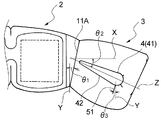
マスク本体2の縦(Y)方向に対する、耳掛け部連結部11の内端部11Aの傾きθ1(図5参照)は、好ましくは5〜30度であり、特に好ましくは10〜25度である。
The inner end portion 11 </ b> A of the ear hook portion connecting portion 11 defines the deployment direction of the ear hook portion 3. As shown in FIG. 1, when the inner end 11 </ b> A of the ear hook connecting portion 11 is narrowed downward with respect to the longitudinal (Y) direction of the mask main body 2, the pair of ear hooks 3 are connected to the mask. The main body 2 is developed obliquely downward from the vicinity of both outer end portions in the lateral (X) direction. In general, since the height of the human eye is higher than the upper end of the base of the ear, that is, the position of the ear is lower than the position of the eye, the ear hook 3 is in the lateral (X) direction of the mask body 2. When it develops diagonally downward from the vicinity of the outer end, the mask body 2 can easily fit the face when worn.
The inclination θ1 (see FIG. 5) of the inner end portion 11A of the ear hook connecting portion 11 with respect to the longitudinal (Y) direction of the mask main body 2 is preferably 5 to 30 degrees, and particularly preferably 10 to 25 degrees. .

耳掛け部連結部11は、図2に示すように、そのマスク本体2の横(X)方向の内端部11Aの下端部11Bが、マスク本体2の横(X)方向外側に後退するように丸みを帯びている。耳掛け部連結部11の内端部11Aの下端部11Bは、使用時(耳掛け部3を展開して装着する際)に最も負荷が掛かる部分であるため、負荷を逃がし、基材シート31の素材の破れや解れ(ほつれ)等を防止することが好ましい。そのため、耳掛け部連結部11の内端部11Aの下端部11Bが丸みを帯びていると、負荷を逃がし、基材シート31の素材の解れ等を効果的に防止することができる。   As shown in FIG. 2, the ear hook portion connecting portion 11 is configured such that the lower end portion 11 </ b> B of the inner end portion 11 </ b> A in the horizontal (X) direction of the mask main body 2 recedes outward in the horizontal (X) direction of the mask main body 2. It is rounded. The lower end portion 11B of the inner end portion 11A of the ear hook portion connecting portion 11 is a portion to which the load is most applied during use (when the ear hook portion 3 is unfolded and mounted). It is preferable to prevent the material from being broken or broken (frayed). Therefore, when the lower end portion 11B of the inner end portion 11A of the ear hook connecting portion 11 is rounded, it is possible to release the load and effectively prevent the material of the base sheet 31 from being unwound.

丸みを帯びた下端部11Bの幅(マスク本体2の横(X)方向の幅)は、着用時における耳掛け部3のきつさに影響を与えない観点から、好ましくは0.5mm以上、特に1mm以上である。また、略直線状の内端部11Aがマスク本体2の横(X)方向外側に後退し始める部分は、マスク本体2の縦(Y)方向の高さが、マスク本体2の下縁から好ましくは1mm以上であり、特に好ましくは3〜30mmであり、さらに好ましくは5〜20mmである。   The width of the rounded lower end portion 11B (the width in the horizontal (X) direction of the mask body 2) is preferably 0.5 mm or more, particularly from the viewpoint of not affecting the tightness of the ear hook 3 when worn. 1 mm or more. Further, the height of the mask main body 2 in the vertical (Y) direction is preferably from the lower edge of the mask main body 2 in the portion where the substantially linear inner end portion 11A starts to recede to the outside in the horizontal (X) direction of the mask main body 2. Is 1 mm or more, particularly preferably 3 to 30 mm, and further preferably 5 to 20 mm.

開口部4は横長に設けられている。開口部4が横長であると、開口部4に耳を掛けやすく、特に耳たぶの小さい人でも耳を掛けやすい。また、装着時のフィット性が高くなる。さらに、耳掛け部3を閉じた状態であっても視覚的に耳掛け部3であることを視認しやすい。   The opening 4 is provided horizontally. If the opening 4 is horizontally long, it is easy to put an ear on the opening 4, and even a person with a small earlobe is particularly likely to make an ear. Moreover, the fitting property at the time of mounting becomes high. Furthermore, it is easy to visually recognize that it is the ear hook 3 even when the ear hook 3 is closed.

図1及び図5に示す耳掛け部3を展開した状態において、開口部4は、マスク本体2の横(X)方向に対して傾いて延びている。開口部4が延びる方向とは、開口部4の上縁部41の近似直線と開口部4の下縁部42の近似直線とを二分する直線(二等分線)が延びる方向(図5に示すZ方向)である。
一般に人間の耳の位置は目の位置よりも低いため、開口部4がマスク本体2の横(X)方向に対して傾いて延びていることにより、着用時にマスク本体2の顔へのフィット性が向上する。
マスク本体2の横(X)方向に対する開口部4の延びる方向(Z方向)の傾きθ2(図5参照)は、顔へのマスク本体2のフィット性を向上させる観点から、好ましくは10〜60度であり、特に好ましくは20〜50度である。
In the state where the ear hook 3 shown in FIGS. 1 and 5 is developed, the opening 4 extends while being inclined with respect to the lateral (X) direction of the mask main body 2. The direction in which the opening 4 extends is the direction in which a straight line (bisector) that bisects the approximate straight line of the upper edge 41 of the opening 4 and the approximate straight line of the lower edge 42 of the opening 4 (see FIG. 5). Z direction).
In general, since the position of the human ear is lower than the position of the eye, the opening 4 is inclined with respect to the lateral (X) direction of the mask body 2, and thus fits to the face of the mask body 2 when worn. Will improve.
The inclination θ2 (see FIG. 5) in the extending direction (Z direction) of the opening 4 with respect to the lateral (X) direction of the mask body 2 is preferably 10 to 60 from the viewpoint of improving the fit of the mask body 2 to the face. Degree, particularly preferably 20 to 50 degrees.

横長の開口部4の大きさは、その延びる方向(Z方向)と直交する方向の長さが好ましくは1〜7cmであり、その延びる方向の長さが好ましくは2〜10cmである。特に、前記直交する方向の長さが2〜4cmで、前記延びる方向の長さが3〜7cmであると、ほとんどの人の耳の大きさに適合するため更に好ましい。   The size of the horizontally long opening 4 is preferably 1 to 7 cm in the direction perpendicular to the extending direction (Z direction), and preferably 2 to 10 cm in the extending direction. In particular, it is more preferable that the length in the orthogonal direction is 2 to 4 cm and the length in the extending direction is 3 to 7 cm because it matches the size of most human ears.

開口部4は、その延びる方向(Z方向)に沿う上縁部41と下縁部42との間隔が、その延びる方向の外端部44に向けて徐々に広がっている。上縁部41と下縁部42との間隔が外端部44に向けて徐々に広がっていると、開口部4を耳に掛けやすく、また、開口部4が耳の後ろの形に沿うため、フィット性が良い。さらに、開口部4においては、耳掛け部連結部11に近い部分には着用時に負荷が掛かりやすいため、この負荷による基材シート31への負担を少なくする観点から、上縁部41と下縁部42との間隔は狭い方が好ましい。   In the opening 4, the distance between the upper edge 41 and the lower edge 42 along the extending direction (Z direction) gradually increases toward the outer end 44 in the extending direction. When the distance between the upper edge portion 41 and the lower edge portion 42 is gradually widened toward the outer end portion 44, the opening portion 4 can be easily put on the ear, and the opening portion 4 follows the shape behind the ear. Good fit. In addition, in the opening 4, a portion close to the ear hooking portion connecting portion 11 is likely to be loaded when worn. From the viewpoint of reducing the load on the base sheet 31 due to this load, the upper edge portion 41 and the lower edge It is preferable that the distance from the portion 42 is narrow.

開口部4における上縁部41と下縁部42との間隔は、開口部4の延びる方向(Z方向)の内側において、好ましくは3cm以下であり、特に好ましくは0.1〜1cmである。また、耳への開口部4の掛けやすさ、フィット性、基材シート31への負担の少なさを向上させる観点から、上縁部41と下縁部42との間隔は、開口部4の延びる方向の外側において、好ましくは2〜7cmであり、特に好ましくは3〜5cmである。   The distance between the upper edge portion 41 and the lower edge portion 42 in the opening 4 is preferably 3 cm or less, particularly preferably 0.1 to 1 cm inside the direction in which the opening 4 extends (Z direction). Further, from the viewpoint of improving ease of placing the opening 4 on the ear, fit, and less burden on the base material sheet 31, the distance between the upper edge 41 and the lower edge 42 is determined by the distance between the openings 4. Outside the extending direction, it is preferably 2 to 7 cm, particularly preferably 3 to 5 cm.

第1実施形態においては、開口部4は、その上縁部41及び下縁部42が直線状で、その延びる方向(Z方向)の内縁部43及び外縁部44が円弧状である。耳の後ろの形は丸いので、開口部4の外縁部44が円弧状であると、開口部4が耳にフィットしやすい。また、開口部4の内縁部43及び外縁部44が円弧状であると、開口部4の外観が印象的にも好ましくなる。   In the first embodiment, the upper edge 41 and the lower edge 42 of the opening 4 are linear, and the inner edge 43 and the outer edge 44 in the extending direction (Z direction) are arcuate. Since the shape behind the ear is round, if the outer edge 44 of the opening 4 is arcuate, the opening 4 can easily fit into the ear. Further, when the inner edge 43 and the outer edge 44 of the opening 4 are arcuate, the appearance of the opening 4 is impressively preferable.

耳掛け部3には、開口部4の外端部44近傍から、マスク本体2の縦(Y)方向下向きに延びる下向きスリット51が設けられている。下向きスリット51は、実質的に開口面積を有していない切れ込みからなり、耳に掛けるときに必要に応じて開くことができる。下向きスリット51が設けられていると、耳が大きい人及び耳が小さい人の何れに対しても、特に、耳たぶが大きい人及び耳たぶが小さい人の何れに対しても、下向きスリット51の開き具合が変わることによって対応することができる。また、使用時に下向きスリット51が広がり、外縁部44近傍の基材シート31が折れることによって、耳への基材シート31の感触が優しくなる。
下向きスリット51の長さは、好ましくは1〜30mmであり、特に好ましくは5〜15mmである。マスク本体2の縦(Y)方向に対する下向きスリット51の傾きθ3(図5参照)は、好ましくは5〜30度であり、特に好ましくは10〜25度である。
The ear hook 3 is provided with a downward slit 51 extending downward from the vicinity of the outer end 44 of the opening 4 in the longitudinal (Y) direction of the mask body 2. The downward slit 51 is formed by a cut having substantially no opening area, and can be opened as needed when hung on the ear. If the downward slit 51 is provided, the degree of opening of the downward slit 51 for both a person with a large ear and a person with a small ear, especially for a person with a large earlobe and a person with a small earlobe. Can be accommodated by changing Moreover, the downward slit 51 spreads at the time of use, and the base material sheet 31 in the vicinity of the outer edge portion 44 is folded, so that the touch of the base material sheet 31 to the ear becomes gentle.
The length of the downward slit 51 is preferably 1 to 30 mm, and particularly preferably 5 to 15 mm. The inclination θ3 (see FIG. 5) of the downward slit 51 with respect to the longitudinal (Y) direction of the mask body 2 is preferably 5 to 30 degrees, and particularly preferably 10 to 25 degrees.

耳掛け部3は、図2に示すように、耳掛け部連結部11を折り返し線としてマスク本体2の横(X)方向中央側に折り返すと、耳掛け部3をマスク本体2の第1の面23側に閉じた状態において、耳掛け部3の上縁及び下縁がマスク本体2の上縁及び下縁と一致するようになっている。
耳掛け部3がこのような形状を有していると、製造時にマスク本体2及び耳掛け部3を同時に切断して形成できる利点がある。また、使用前の状態において、第1の面23が一対の耳掛け部3,3によって保護されて清浄な状態に保持できる利点がある。更に、耳掛け部3がマスク本体2から少なくともはみ出ていない構成とすると、出荷時の包装工程の際に、耳掛け部3を閉じ、場合によってはマスク本体2を縦(Y)方向の中心線で横(X)方向に2つ折りにした状態において包装できるため、包装が容易であるという利点もある。
As shown in FIG. 2, when the ear hooking portion 3 is folded back to the center side in the horizontal (X) direction of the mask main body 2 with the ear hooking portion connecting portion 11 as a folding line, In the state closed to the surface 23 side, the upper edge and the lower edge of the ear hook 3 coincide with the upper edge and the lower edge of the mask body 2.
When the ear hook 3 has such a shape, there is an advantage that the mask main body 2 and the ear hook 3 can be simultaneously cut at the time of manufacture. Further, there is an advantage that the first surface 23 is protected by the pair of ear hooks 3 and 3 and can be kept in a clean state before use. Further, if the ear hook 3 is configured not to protrude at least from the mask main body 2, the ear hook 3 is closed during the packaging process at the time of shipment, and in some cases, the mask main body 2 is centered in the longitudinal (Y) direction. Since packaging can be performed in a state of being folded in the lateral (X) direction, there is also an advantage that packaging is easy.

使用前の状態においては、一対の耳掛け部3,3は、マスク本体2の第1の面23側に閉じられ、それらの横方向外端部(展開状態における外端部)同士が互いに対向当接して、連結域32によって部分的に連結されている。連結域32は、例えばミシン目によって形成されている。この連結域32によって、使用前の状態の一対の耳掛け部3,3は一体となり、一体化した一対の耳掛け部3,3によって、第1の面23を確実に覆うことができる。一体化した一対の耳掛け部3,3は、連結域32を引き裂くことにより分離することができる。   In a state before use, the pair of ear hooks 3 and 3 are closed to the first surface 23 side of the mask body 2 and their lateral outer ends (outer ends in the unfolded state) are opposed to each other. Abutting and partially connected by the connecting region 32. The connection area 32 is formed by perforations, for example. By this connection region 32, the pair of ear hooks 3 and 3 in a state before use are united, and the first surface 23 can be reliably covered by the pair of integrated ear hooks 3 and 3. The pair of integrated ear hooks 3, 3 can be separated by tearing the connection area 32.

一体化した一対の耳掛け部3,3には、連結域32の上端部近傍及び下端部近傍にそれぞれ隣接して、上下に一対の誘導切れ込み33,33が設けられている。一対の誘導切れ込み33は、矢先形状の切れ込みからなり、その矢先方向を対向させている。誘導切れ込み33が設けられていると、一体化した一対の耳掛け部3,3において、連結域32を引き裂いて分離する際に、連結域32をスムーズに引き裂くことができる。   The pair of integrated ear hooks 3, 3 are provided with a pair of guide cuts 33, 33 vertically adjacent to the vicinity of the upper end and the vicinity of the lower end of the connection area 32. A pair of induction | guidance | derivation cut | notch 33 consists of a cut of an arrow tip shape, and has made the arrow tip direction oppose. When the guide cut 33 is provided, the connecting region 32 can be smoothly torn when the connecting region 32 is torn and separated in the pair of integrated ear hooks 3 and 3.

耳掛け部3は、図2に示す閉じた状態から、耳掛け部連結部11を折り返し線として展開すると、図1に示すように、耳掛け部3の全体形状が外側下方に傾斜して展開する。   When the ear hooking portion 3 is expanded from the closed state shown in FIG. 2 with the ear hooking portion connecting portion 11 as a fold line, the entire shape of the ear hooking portion 3 is inclined outward and downward as shown in FIG. To do.

図1に示すように、マスク本体2は、その横(X)方向中央からその横方向外側それぞれに向けて、その縦(Y)方向長さが徐々に短くなっている。このような形状を有するマスク本体2によれば、マスク本体2を目に当てやすく、マスク本体2が顔にフィットしやすい。
また、耳掛け部3は、展開した状態において、その横方向内側からその横方向外側それぞれに向けて、その縦方向長さが徐々に長くなっている。このような形状を有する耳掛け部3によれば、耳掛け部3の横方向外側において、開口部4の上下に位置する領域の幅を大きく確保でき、基材シート31への応力負担を低減させることができる。
As shown in FIG. 1, the length of the mask body 2 is gradually shortened from the center in the horizontal (X) direction toward the outside in the horizontal direction. According to the mask body 2 having such a shape, the mask body 2 can be easily applied to the eyes, and the mask body 2 can be easily fitted to the face.
Further, in the unfolded state, the ear hooking portion 3 gradually increases in length in the vertical direction from the inner side in the horizontal direction to the outer side in the horizontal direction. According to the ear hook 3 having such a shape, the width of the region located above and below the opening 4 can be secured on the lateral outer side of the ear hook 3, and the stress load on the base sheet 31 is reduced. Can be made.

耳掛け部3には、開口部4における円弧状の外縁部44から放射状に延びる1本又は複数本の放射状スリット52が設けられている。放射状スリット52が設けられていると、使用時に放射状スリット52が広がり、円弧状の外縁部44近傍の基材シート31が折れて、耳への基材シート31の当たりが優しくなる。放射状スリット52の長さは、好ましくは0.1〜15mm、特に0.5〜5mmである。放射状スリット52の本数は、好ましくは2本以上であり、特に好ましくは3本以上である。第1実施形態においては、2本の放射状スリット52が設けられている。   The ear hook 3 is provided with one or a plurality of radial slits 52 extending radially from the arcuate outer edge 44 in the opening 4. When the radial slits 52 are provided, the radial slits 52 widen during use, the base sheet 31 in the vicinity of the arcuate outer edge 44 is broken, and the base sheet 31 hits the ear gently. The length of the radial slit 52 is preferably 0.1 to 15 mm, in particular 0.5 to 5 mm. The number of radial slits 52 is preferably 2 or more, and particularly preferably 3 or more. In the first embodiment, two radial slits 52 are provided.

次に、マスク本体(蒸気温熱本体)2における蒸気温熱機能について詳述する。蒸気温熱発生材21は、被酸化性金属を含んでおり、被酸化性金属が酸素と接触することによる酸化反応で生じた熱を利用して、所定温度に加熱された水蒸気を発生する材である。   Next, the steam temperature function in the mask body (steam temperature body) 2 will be described in detail. The vapor heat generating material 21 contains an oxidizable metal, and is a material that generates water vapor heated to a predetermined temperature using heat generated by an oxidation reaction caused by contact of the oxidizable metal with oxygen. is there.

第1の面23は空気及び水蒸気の透過が可能な面になっている。つまり、第1の面23は通気面になっている。第2の面24は、第1の面23と同様に空気及び水蒸気の透過が可能な面になっているか、または、第1の面23よりも空気及び水蒸気の透過の程度が低い面、つまり、難通気面になっている。さらに、第2の面24は、空気及び水蒸気が実質的に透過しない面、すなわち非通気面になっていてもよい。   The first surface 23 is a surface capable of transmitting air and water vapor. That is, the first surface 23 is a ventilation surface. Similar to the first surface 23, the second surface 24 is a surface capable of transmitting air and water vapor, or a surface having a lower degree of air and water vapor transmission than the first surface 23, that is, the surface. It has a breathable surface. Furthermore, the second surface 24 may be a surface that does not substantially transmit air and water vapor, that is, a non-venting surface.

蒸気温熱本体2は、その第1の面23の側が着用者の肌面に対向し、第2の面24の側が外方を向くように使用される。蒸気温熱発生材21の発熱によって発生した水蒸気は、第1の面23を通じ、対象物である肌面に付与されるようになっている。   The steam heat main body 2 is used so that the first surface 23 side faces the wearer's skin surface and the second surface 24 side faces outward. The water vapor generated by the heat generated by the steam temperature generating material 21 is applied to the skin surface as the object through the first surface 23.

蒸気温熱本体2における第1の面23及び第2の面24は、図1及び図2に示すように、それぞれシート材26,27から構成されている。蒸気温熱本体2の収容部22は、シート材26,27の所定位置を収容部周縁接合部25によって接合することで形成される。収容部周縁接合部25は、周状で、蒸気温熱本体2の横(X)方向中央部において、上下方向に括れ、略瓢箪形状となっている。そのため、収容部22は、蒸気温熱本体2の横(X)方向中央部の連結空間28(図1(b)参照)において連通した形態で、2個の領域に区画されている。この領域ごとに1個の蒸気温熱発生材21が配設されている。   As shown in FIGS. 1 and 2, the first surface 23 and the second surface 24 of the steam heat main body 2 are composed of sheet materials 26 and 27, respectively. The accommodating portion 22 of the steam temperature main body 2 is formed by joining predetermined positions of the sheet materials 26 and 27 with the accommodating portion peripheral edge joining portion 25. The housing peripheral edge joint portion 25 has a circumferential shape, and is bound in the vertical direction at the central portion in the horizontal (X) direction of the steam heat main body 2 and has a substantially bowl shape. Therefore, the accommodating portion 22 is partitioned into two regions in a form communicating with each other in the connecting space 28 (see FIG. 1B) in the central portion in the horizontal (X) direction of the steam heat main body 2. One steam temperature generating material 21 is disposed for each region.

2個の収容部22が連通していることによって、2個の蒸気温熱発生材21間での空気の流通が均一になり、蒸気温熱発生材21の発熱及び水蒸気の発生が均一になりやすい。また、蒸気温熱発生材21が中央部の連結空間28に存在しないため、包装時にマスク本体2を横(X)方向に2つに折り畳むことができ、また連結空間28の下部において、マスク本体2にスリット29(図1(b)参照)を形成することができるので、鼻部分へのマスク本体2の装着性が向上する。
反対に、本発明の実施形態においては、収容部22全体に亘って蒸気温熱発生材21を収容することもできる(図示せず)。
Since the two accommodating portions 22 communicate with each other, the air flow between the two steam temperature heat generating materials 21 becomes uniform, and the heat generation of the steam temperature heat generating material 21 and the generation of water vapor tend to be uniform. Further, since the steam heat generating material 21 does not exist in the central connection space 28, the mask main body 2 can be folded in two in the lateral (X) direction during packaging, and the mask main body 2 is located below the connection space 28. Since the slits 29 (see FIG. 1B) can be formed in the mask, the attachment of the mask body 2 to the nose portion is improved.
On the contrary, in the embodiment of the present invention, the steam temperature heat generating material 21 can be accommodated over the entire accommodating portion 22 (not shown).

収容部周縁接合部25の両側縁部は、蒸気温熱本体2(シート材26,27)の横(X)方向の両外端部よりも横方向内側に位置しており、更には耳掛け部連結部11の内端部11Aよりも横方向内側に位置している。蒸気温熱本体2における収容部周縁接合部25の両側縁部よりも外側は、耳掛け部連結部11又は接着剤(図示せず)により接合されている。   Both side edge portions of the housing peripheral edge joint portion 25 are located on the inner side in the lateral direction with respect to both outer end portions in the lateral (X) direction of the steam heat main body 2 (sheet materials 26 and 27), and further the ear hooking portion. It is located on the inner side in the lateral direction than the inner end portion 11 </ b> A of the connecting portion 11. The outer side of the both sides of the accommodating portion peripheral joint portion 25 in the steam heat main body 2 is joined by the ear hook connecting portion 11 or an adhesive (not shown).

第1実施形態における蒸気温熱本体2においては、目及び目周囲に広く水蒸気が適用されることに加えて、蒸気温熱本体2が酸素と接触後、目及び目周囲に当接する面である第1の面23から、水蒸気が1〜30分間、好ましくは5〜25分間発生し、且つ蒸気温熱本体2の適用期間中、蒸気温熱本体2が適用された皮膚表面の温度を、34〜43℃に高め、好ましくは36〜41℃に高め、その温度を1〜120分間維持することで、近見反応の三徴の改善に高い効果が現れる。なお、皮膚表面温度は、水蒸気の発生終了後でも保温効果によって低下しにくくなっているので、前記の水蒸気の持続時間よりも、前記の皮膚表面温度の維持時間の方が長くなる。   In the steam temperature main body 2 in the first embodiment, in addition to the wide application of water vapor to the eyes and the periphery of the eyes, the steam temperature main body 2 is a surface that comes into contact with the eyes and the periphery of the eyes after contact with oxygen. From the surface 23, water vapor is generated for 1 to 30 minutes, preferably 5 to 25 minutes, and the temperature of the skin surface to which the steam thermal body 2 is applied during the application period of the steam thermal body 2 is 34 to 43 ° C. By raising the temperature, preferably 36-41 ° C., and maintaining the temperature for 1-120 minutes, a high effect appears in improving the trilogy of near vision reaction. In addition, since the skin surface temperature is less likely to decrease due to the heat retaining effect even after the generation of water vapor, the time for maintaining the skin surface temperature is longer than the duration of the water vapor.

蒸気温熱本体2における水蒸気の発生の持続時間は、図6に示す装置Qを用いて次のように測定される。図6に示す装置Qは、アルミニウム製の測定室(容積2.1L)Q1と、測定室Q1の下部に除湿空気(湿度2%未満、流量2.1L/分)を流入させる流入路Q2と、測定室Q1の上部から空気を流出させる流出路Q3とを備えている。流入路Q2には、入口温湿度計Q4及び入口流量計Q5が取り付けられている。一方、流出路Q3には、出口温湿度計Q6及び出口流量計Q7が取り付けられている。測定室Q1内には温度計(サーミスタ)Q8が取り付けられている。温度計Q8としては、温度分解能が0.01℃程度のものを使用する。   The duration of the generation of water vapor in the steam temperature main body 2 is measured as follows using the apparatus Q shown in FIG. The apparatus Q shown in FIG. 6 includes an aluminum measurement chamber (volume 2.1 L) Q1, and an inflow channel Q2 for allowing dehumidified air (humidity less than 2%, flow rate 2.1 L / min) to flow into the lower portion of the measurement chamber Q1. And an outflow channel Q3 for allowing air to flow out from the upper part of the measurement chamber Q1. An inlet temperature / humidity meter Q4 and an inlet flow meter Q5 are attached to the inflow channel Q2. On the other hand, an outlet temperature and humidity meter Q6 and an outlet flow meter Q7 are attached to the outflow channel Q3. A thermometer (thermistor) Q8 is attached in the measurement chamber Q1. A thermometer having a temperature resolution of about 0.01 ° C. is used as the thermometer Q8.

測定環境温度:30℃(30±1℃)において、蒸気温熱本体2を包装材から取り出し、その水蒸気放出面を上にして測定室Q1に載置する。金属球(4.5g)を取り付けた温度計Q8をその上に載せる。この状態で測定室Q1の下部から除湿空気を流す。入口温湿度計Q4及び出口温湿度計Q6で計測される温度及び湿度から、測定室Q1に空気が流入する前後の絶対湿度の差を求める。更に、入口流量計Q5及び出口流量計Q7で計測される流量から、蒸気温熱本体2が放出した水蒸気量を算出する。この装置の詳細は、本出願人の先の出願に係る特開2004−73688号公報に記載されている。一方、皮膚表面の温度は、LTST08−12(サーミスター式の表面温度測定器;グラム社)を用いて測定する。   At a measurement environment temperature of 30 ° C. (30 ± 1 ° C.), the steam heat main body 2 is taken out of the packaging material and placed in the measurement chamber Q1 with its water vapor discharge surface facing up. A thermometer Q8 attached with a metal ball (4.5 g) is placed thereon. In this state, dehumidified air is flowed from the lower part of the measurement chamber Q1. From the temperature and humidity measured by the inlet temperature / humidity meter Q4 and the outlet temperature / humidity meter Q6, a difference in absolute humidity before and after the air flows into the measurement chamber Q1 is obtained. Furthermore, the amount of water vapor released from the steam heat main body 2 is calculated from the flow rates measured by the inlet flow meter Q5 and the outlet flow meter Q7. Details of this apparatus are described in Japanese Patent Application Laid-Open No. 2004-73688, which is related to the earlier application of the present applicant. On the other hand, the temperature of the skin surface is measured using LTST08-12 (Thermistor type surface temperature measuring instrument; Gram).

第1実施形態における蒸気温熱本体2においては、第1の面23及び第2の面24の通気度を適切に調整することで、第1の面23を通じて水蒸気が優先的に放出されるようになっている。これに加えて、第1の面23及び第2の面24の通気度を適切に調整することで、蒸気温熱の発生の持続時間を前記の範囲内とすることが容易となる。また、蒸気温熱本体2が適用された皮膚表面の温度を前記の範囲内とすることが容易となる。具体的には、第1実施形態においては、第2の面24の通気度を、第1の面23の通気度と同じか、より大きくしている。 例えば、第2の面24が通気性である場合には、該面24の通気度を好ましくは100〜60000秒、更に好ましくは4000〜40000秒とする。また、第2の面24の通気度が第1の面23の通気度よりも十分に大きい場合には、第2の面24の通気度を、第1の面23の通気度の5倍以上、特に10倍以上、とりわけ100倍以上とすることが好ましい。
さらに、第1の面23の通気度そのものは、0.01〜15000秒、特に0.01〜10000秒であることが好ましい。
In the steam heat main body 2 in the first embodiment, the water vapor is preferentially released through the first surface 23 by appropriately adjusting the air permeability of the first surface 23 and the second surface 24. It has become. In addition to this, by appropriately adjusting the air permeability of the first surface 23 and the second surface 24, it becomes easy to set the duration of generation of the steam temperature within the above range. Moreover, it becomes easy to make the temperature of the skin surface to which the steam temperature main body 2 is applied within the above range. Specifically, in the first embodiment, the air permeability of the second surface 24 is the same as or greater than the air permeability of the first surface 23. For example, when the second surface 24 is air permeable, the air permeability of the surface 24 is preferably 100 to 60000 seconds, and more preferably 4000 to 40000 seconds. In addition, when the air permeability of the second surface 24 is sufficiently larger than the air permeability of the first surface 23, the air permeability of the second surface 24 is set to 5 times or more of the air permeability of the first surface 23. In particular, it is preferably 10 times or more, particularly preferably 100 times or more.
Furthermore, the air permeability itself of the first surface 23 is preferably 0.01 to 15000 seconds, and particularly preferably 0.01 to 10,000 seconds.

ここで、通気度は、JIS P8117に記載の方法によって測定され、一定の圧力のもとで100mlの空気が6.42cm2の面積を通過する時間で定義されるものである。この通気度が大きいことは、空気の通過に時間が掛かることを意味している。即ち通気性が低いことを意味している。逆に、通気度が小さいことは、通気性が高いことを意味している。このように、通気度の大小と通気性の高低とは逆の関係になっている。通気性に関して第1の面23及び第2の面24を比較すると、第1の面23の通気性が、第2の面24の通気性よりも高くなっている。つまり、第2の面24は、非通気性であるか、又は難通気性(即ち、通気性を有するものの、第1の面23よりも低い通気性を有している)である。 Here, the air permeability is measured by the method described in JIS P8117, and is defined as the time required for 100 ml of air to pass through an area of 6.42 cm 2 under a constant pressure. A large air permeability means that it takes time to pass air. That is, the air permeability is low. Conversely, a low air permeability means high air permeability. Thus, the magnitude of the air permeability is opposite to the air permeability. When comparing the first surface 23 and the second surface 24 with respect to the air permeability, the air permeability of the first surface 23 is higher than the air permeability of the second surface 24. That is, the second surface 24 is non-breathable or hardly breathable (that is, although it has breathability, it has lower breathability than the first surface 23).

収容部22に収容される蒸気温熱発生材21は、被酸化性金属、反応促進剤、電解質及び水を含む。そのような蒸気温熱発生材21は、例えば発熱シート又は発熱粉体からなる。蒸気温熱発生材21が発熱シートからなる場合には、発熱シートは被酸化性金属、反応促進剤、繊維状物、電解質及び水を含む繊維シートから構成されていることが好ましい。つまり、発熱シートは、被酸化性金属、反応促進剤、繊維状物及び電解質を含む繊維シートが含水状態となっているものであることが好ましい。特に、発熱シートは、被酸化性金属、反応促進剤及び繊維状物を含有する成形シートに、電解質水溶液を含有させて構成されていることが好ましい。   The steam heat generating material 21 accommodated in the accommodating part 22 contains an oxidizable metal, a reaction accelerator, an electrolyte, and water. Such a steam temperature generating material 21 is made of, for example, a heat generating sheet or a heat generating powder. When the steam heat generating material 21 is composed of a heat generating sheet, the heat generating sheet is preferably composed of a fiber sheet containing an oxidizable metal, a reaction accelerator, a fibrous material, an electrolyte, and water. That is, it is preferable that the exothermic sheet is one in which a fiber sheet containing an oxidizable metal, a reaction accelerator, a fibrous material, and an electrolyte is in a water-containing state. In particular, the exothermic sheet is preferably configured by containing an electrolyte aqueous solution in a molded sheet containing an oxidizable metal, a reaction accelerator, and a fibrous material.

本発明においては、目用に使用する点から、湿式抄造により得られたシート状物や、発熱粉体を紙等で挟持してなる積層体等が好ましい。そのような発熱シートは、例えば本出願人の先の出願に係る特開2003−102761号公報に記載の湿式抄造法や、ダイコーターを用いたエクストルージョン法を用いて製造することができる。一方、蒸気温熱発生材21が発熱粉体からなる場合には、発熱粉体は、被酸化性金属、反応促進剤、保水剤、電解質及び水を含んで構成されていることが好ましい。発熱シート及び発熱粉体のうち、どのような姿勢においても目及び目周囲へ蒸気温熱を均一に適用し得る点から、発熱シートを用いることが好ましい。また、発熱シートは、発熱粉体に比較して、発熱の温度分布を均一化することが容易であり、また、被酸化性金属の担持能力が優れている点からも有利である。   In the present invention, from the viewpoint of use for eyes, a sheet-like material obtained by wet papermaking, a laminate formed by sandwiching exothermic powder with paper or the like, and the like are preferable. Such a heat generating sheet can be manufactured using, for example, the wet papermaking method described in Japanese Patent Application Laid-Open No. 2003-102761 related to the previous application of the present applicant, or the extrusion method using a die coater. On the other hand, when the steam heat generating material 21 is made of exothermic powder, it is preferable that the exothermic powder includes an oxidizable metal, a reaction accelerator, a water retention agent, an electrolyte, and water. Of the heat generating sheet and the heat generating powder, it is preferable to use the heat generating sheet from the viewpoint that the vapor temperature heat can be uniformly applied to the eyes and around the eyes in any posture. Further, the heat generating sheet is more advantageous than the heat generating powder because the temperature distribution of heat generation can be made uniform easily and the ability to support an oxidizable metal is excellent.

蒸気温熱発生材21が発熱シートからなる場合、該発熱シートは60〜90重量%の被酸化性金属、5〜25重量%の反応促進剤及び5〜35重量%の繊維状物を含む成形シートに、該成形シート100重量部に対して、1〜15重量%の電解質を含む電解質水溶液が20〜80重量部含有されて構成されていることが好ましい。一方、蒸気温熱発生材21が発熱粉体からなる場合、該発熱粉体は、30〜80重量%の被酸化性金属、1〜25重量%の反応促進剤、3〜25重量%の保水剤を含む固形分100重量部に対して、0.3〜10重量%の電解質を含む電解質水溶液が20〜70重量部、30〜60重量部の水から構成されていることが好ましい。発熱シートや発熱粉体を構成する各種材料としては、当該技術分野において通常用いられているものと同様のものを用いることができる。また、先に述べた特開2003−102761号公報に記載の材料を用いることもできる。   When the steam heat generating material 21 is a heat generating sheet, the heat generating sheet is a molded sheet containing 60 to 90% by weight of an oxidizable metal, 5 to 25% by weight of a reaction accelerator, and 5 to 35% by weight of a fibrous material. Furthermore, it is preferable that 20 to 80 parts by weight of an aqueous electrolyte solution containing 1 to 15% by weight of electrolyte is contained with respect to 100 parts by weight of the molded sheet. On the other hand, when the steam heat generating material 21 is composed of exothermic powder, the exothermic powder comprises 30 to 80% by weight of an oxidizable metal, 1 to 25% by weight of a reaction accelerator, and 3 to 25% by weight of a water retention agent. The electrolyte aqueous solution containing 0.3 to 10% by weight of electrolyte is preferably composed of 20 to 70 parts by weight and 30 to 60 parts by weight of water based on 100 parts by weight of the solid content. As various materials constituting the heat generating sheet and the heat generating powder, the same materials as those usually used in the technical field can be used. Further, the materials described in JP-A-2003-102761 described above can also be used.

第1実施形態のアイマスク1は、その使用前は、その全体が酸素バリア性を有する包装材(図示せず)によって包装されて、蒸気温熱本体2の蒸気温熱発生材21が空気中の酸素と接触しないようになっている。酸素バリア性の材料としては、例えば、その酸素透過係数(ASTM D3985)が10cm3・mm/(m2・day・MPa)以下、特に2cm3・mm/(m2・day・MPa)以下のものが好ましい。具体的には、エチレン−ビニルアルコール共重合体やポリアクリロニトリル等のフィルム、又はそのようなフィルムにセラミック若しくはアルミニウム等を蒸着したフィルムが挙げられる。 Prior to its use, the eye mask 1 of the first embodiment is entirely packaged by a packaging material (not shown) having oxygen barrier properties, and the steam temperature generating material 21 of the steam temperature body 2 is oxygen in the air. To avoid contact. As an oxygen barrier material, for example, the oxygen permeability coefficient (ASTM D3985) is 10 cm 3 · mm / (m 2 · day · MPa) or less, particularly 2 cm 3 · mm / (m 2 · day · MPa) or less. Those are preferred. Specifically, a film of ethylene-vinyl alcohol copolymer, polyacrylonitrile, or the like, or a film obtained by depositing ceramic or aluminum on such a film can be given.

第1実施形態のアイマスク1は、例えば図7に示すように、耳掛け部3を利用して耳に掛けられ、使用される。このような使用形態とすることで、着用者の姿勢(例えば仰臥位や座位等)によらず、蒸気温熱本体2から発生した蒸気温熱を着用者に均一に適用することができる。このことは、蒸気温熱本体2を備えたアイマスク1の使用形態の汎用性が向上する点から有利である。一例として、家で寝転んだ状態で、蒸気温熱本体2を備えたアイマスク1を使用することができる。また、デスクワーク中に目の疲れを感じたときに直ちに使用することも可能である。更に、出張時の移動時(例えば、電車、飛行機、自動車等の中)にも手軽に使用できる。   For example, as shown in FIG. 7, the eye mask 1 of the first embodiment is used by being put on an ear using an ear hook 3. By setting it as such a usage form, the vapor temperature generated from the vapor temperature main body 2 can be uniformly applied to the wearer regardless of the posture of the wearer (for example, the supine position or the sitting position). This is advantageous in that the versatility of the usage pattern of the eye mask 1 including the steam temperature main body 2 is improved. As an example, the eye mask 1 provided with the steam heat main body 2 can be used while lying down at home. It can also be used immediately when eyestrain is felt during desk work. Furthermore, it can be used easily when traveling on a business trip (for example, in a train, airplane, car, etc.).

第1実施形態のアイマスク1によれば、耳掛け部の開口部に耳を掛けやすいと共に着用時にマスク本体が顔にフィットしやすい。詳細には、例えば下記効果(1)〜(7)が奏される。
(1)耳掛け部連結部11の内端部11Aがマスク本体2の縦(Y)方向に対して下方に向けて窄まっているため、一対の耳掛け部3は、マスク本体2の横(X)方向の両外端部近傍それぞれから斜め下向きに展開する。そのため、着用時にマスク本体2が顔にフィットしやすい。
According to the eye mask 1 of 1st Embodiment, it is easy to put an ear on the opening part of an ear hook part, and a mask main body tends to fit a face at the time of wear. Specifically, for example, the following effects (1) to (7) are exhibited.
(1) Since the inner end portion 11 </ b> A of the ear hanger connecting portion 11 is narrowed downward with respect to the longitudinal (Y) direction of the mask main body 2, the pair of ear hanger portions 3 are located on the side of the mask main body 2. It develops diagonally downward from the vicinity of both outer end portions in the (X) direction. Therefore, it is easy for the mask body 2 to fit the face when worn.

(2)開口部4がマスク本体2の横(X)方向に対して傾いて延びているため、着用時にマスク本体2が顔にフィットしやすい。
(3)開口部4の上縁部41と下縁部42との間隔が外端部44に向けて徐々に広がっているため、開口部4を耳に掛けやすく、また、開口部4が耳の後ろの形に沿うため、フィット性が良い。
(4)下向きスリット51が設けられているため、耳が大きい人及び耳が小さい人の何れに対しても、下向きスリット51の開き具合が変わることによって対応することができる。
(2) Since the opening 4 extends while being inclined with respect to the lateral (X) direction of the mask main body 2, the mask main body 2 is easily fitted to the face when worn.
(3) Since the distance between the upper edge portion 41 and the lower edge portion 42 of the opening 4 gradually widens toward the outer end portion 44, the opening 4 can be easily put on the ear, and the opening 4 is in the ear. Fits well because it follows the shape of the back.
(4) Since the downward slit 51 is provided, it is possible to cope with both a person with a large ear and a person with a small ear by changing the degree of opening of the downward slit 51.

(5)耳掛け部連結部11の内端部11Aの下端部11Bが丸みを帯びているため、基材シート31の素材の解れを防止することができる。
(6)一対の耳掛け部3,3は、耳掛け部連結部11を折り返し線としてマスク本体2の横(X)方向中央側に閉じると、耳掛け部3の上縁及び下縁がマスク本体2の上縁及び下縁と一致するようになっているため、マスク本体2及び耳掛け部3を同時に切断して形成することができる。また、使用前の状態において、第1の面23が一対の耳掛け部3,3によって保護されて清浄な状態に保持することができる。
(7)放射状スリット52が設けられているため、使用時に放射状スリット52で基材シート31が折れて、耳への基材シート31の当たりが優しくなる。
(5) Since the lower end portion 11B of the inner end portion 11A of the ear hook connecting portion 11 is rounded, it is possible to prevent the material of the base sheet 31 from being unwound.
(6) When the pair of ear hooks 3 and 3 are closed to the center side in the horizontal (X) direction of the mask main body 2 with the ear hook connecting part 11 as a folding line, the upper and lower edges of the ear hook 3 are masked. Since it matches with the upper edge and the lower edge of the main body 2, the mask main body 2 and the ear hook 3 can be formed by cutting simultaneously. Further, in a state before use, the first surface 23 is protected by the pair of ear hooks 3 and 3 and can be kept clean.
(7) Since the radial slits 52 are provided, the base material sheet 31 is folded at the radial slits 52 at the time of use, and the contact of the base material sheet 31 with the ear becomes gentle.

本発明のアイマスクは、前述した実施形態に制限されることなく、本発明の趣旨を逸脱しない限り適宜変更が可能である。
本発明のアイマスクは、第1実施形態のような蒸気温熱機能によって目を温めることのできるマスクに制限されず、例えば、(1)光を遮る目的の安眠マスクや、(2)電子レンジなどの加熱器で温めて目を温めることのできるマスク、(3)保冷剤等の冷却部材によって目を冷やすことのできるマスク、(4)香り成分を付与してリラックス効果を与えるマスク、(5)発熱体の代わりにビーズや球体が収容されており、目に圧迫感を与えて指圧効果を奏するマスク、(6)電気などで振動させることによりマッサージ効果を奏するマスク、などに変更することが可能である。
The eye mask of the present invention is not limited to the above-described embodiment, and can be appropriately changed without departing from the spirit of the present invention.
The eye mask of the present invention is not limited to the mask that can warm the eyes by the steam heating function as in the first embodiment. For example, (1) a sleep mask for the purpose of blocking light, (2) a microwave oven, etc. (3) A mask that can cool the eyes with a cooling member such as a cryogen, (4) A mask that imparts a relaxing effect by adding a scent component, (5) Instead of a heating element, beads and spheres are housed, and it can be changed to a mask that gives pressure to the eyes and produces acupressure effect, or (6) a mask that produces a massage effect when vibrated by electricity, etc. It is.

図1(a)及び図1(b)は、それぞれ、本発明のアイマスクの第1実施形態について、耳掛け部を展開した状態を示す正面図及び背面図である。FIG. 1A and FIG. 1B are a front view and a rear view, respectively, showing a state in which an ear hooking portion is developed in the first embodiment of the eye mask of the present invention. 図2は、第1実施形態のアイマスクについて、耳掛け部をマスク本体の背面側に閉じた状態を示す背面図である。FIG. 2 is a rear view of the eye mask of the first embodiment showing a state in which the ear hooking portion is closed on the back side of the mask body. 図3(a)及び図3(b)は、それぞれ、図2に示すIIIA−IIIA線断面図及びIIIB−IIIB線断面図である。3A and 3B are a cross-sectional view taken along line IIIA-IIIA and a cross-sectional view taken along line IIIB-IIIB shown in FIG. 2, respectively. 図4は、第1実施形態のアイマスクについて、耳掛け部を展開した状態を示す背面斜視図である。FIG. 4 is a rear perspective view of the eye mask of the first embodiment showing a state in which the ear hooking portion is unfolded. 図5は、第1実施形態のアイマスクに係る各種角度を示すための部分拡大背面図である。FIG. 5 is a partially enlarged rear view for illustrating various angles according to the eye mask of the first embodiment. 図6は、マスク本体における水蒸気発生の持続時間を測定する装置の説明図である。FIG. 6 is an explanatory diagram of an apparatus for measuring the duration of water vapor generation in the mask body. 図7は、第1実施形態のアイマスクを着用した状態を示す図である。FIG. 7 is a diagram illustrating a state in which the eye mask of the first embodiment is worn.

符号の説明Explanation of symbols

1 アイマスク
11 耳掛け部連結部
11A 内端部
11B 下端部
2 マスク本体
21 蒸気温熱発生材
22 収容部
23 第1の面
24 第2の面
3 耳掛け部
31 基材シート
4 開口部
41 上縁部
42 下縁部
43 内縁部
44 外縁部
51 下向きスリット
52 放射状スリット
DESCRIPTION OF SYMBOLS 1 Eye mask 11 Ear hook part connection part 11A Inner edge part 11B Lower end part 2 Mask main body 21 Steam temperature heat generating material 22 Storage part 23 1st surface 24 2nd surface 3 Ear hook part 31 Base material sheet 4 Opening part 41 Top Edge 42 Lower edge 43 Inner edge 44 Outer edge 51 Downward slit 52 Radial slit

Claims (8)

着用時に両目を覆う横長のマスク本体と、該マスク本体の横方向両外端部近傍に設けられ且つ着用時に耳を掛ける一対の耳掛け部とを備えたアイマスクであって、
前記耳掛け部は、基材シートに横長の開口部が設けられて構成されており、
前記マスク本体と一対の前記耳掛け部とは一対の耳掛け部連結部によって連結されており、一対の該耳掛け部連結部は、その該マスク本体の横方向の内端部が該マスク本体の縦方向に対して下方に向けて窄まっており、
前記開口部は、前記マスク本体の横方向に対して傾いて延びていると共に、その延びる方向に沿う上縁部と下縁部との間隔が、その延びる方向の外端部に向けて徐々に広がっており、
前記耳掛け部には、前記開口部の前記外端部近傍から前記マスク本体の縦方向下向きに延びる下向きスリットが設けられているアイマスク。
An eye mask comprising a horizontally long mask body that covers both eyes when worn, and a pair of ear hooks that are provided in the vicinity of both lateral ends of the mask body and that are worn on the ears when worn,
The ear hook part is configured by providing a base sheet with a horizontally long opening,
The mask main body and the pair of ear hooking portions are connected by a pair of ear hooking portion connecting portions, and the pair of the ear hooking portion connecting portions has an inner end portion in the horizontal direction of the mask main body. It is constricted downward with respect to the vertical direction of
The opening extends while being inclined with respect to the lateral direction of the mask body, and the interval between the upper edge and the lower edge along the extending direction is gradually increased toward the outer end in the extending direction. Has spread,
The eye mask is provided with a downward slit extending downward in the vertical direction of the mask body from the vicinity of the outer end of the opening.
前記耳掛け部連結部は、その前記マスク本体の横方向の内端部の下端部が、該マスク本体の横方向外側に後退するように丸みを帯びている請求項1記載のアイマスク。   2. The eye mask according to claim 1, wherein the ear hooking portion connecting portion is rounded so that a lower end portion of an inner end portion in the horizontal direction of the mask main body recedes outward in the horizontal direction of the mask main body. 一対の前記耳掛け部は、前記耳掛け部連結部を折り返し線として前記マスク本体の横方向中央側に閉じると、該耳掛け部の上縁及び下縁が該マスク本体の上縁及び下縁と一致するようになっている請求項1又は2に記載のアイマスク。   When the pair of ear hooks are closed to the center side in the lateral direction of the mask main body with the ear hook connecting portion as a fold line, the upper and lower edges of the ear hook are the upper and lower edges of the mask main body. The eye mask according to claim 1, wherein the eye mask is matched with the eye mask. 前記マスク本体は、その横方向中央からその横方向外側それぞれに向けて、その縦方向長さが徐々に短くなっており、
前記耳掛け部は、展開した状態において、その横方向内側からその横方向外側それぞれに向けて、その縦長さが徐々に長くなっている請求項3記載のアイマスク。
The mask body has a longitudinal length that gradually decreases from the lateral center to the lateral outer side,
4. The eye mask according to claim 3, wherein the ear hook portion has a longitudinal length that gradually increases from an inner side in the lateral direction to an outer side in the lateral direction in the unfolded state. 5.
前記開口部は、その前記上縁部及び前記下縁部が直線状で、その延びる方向の内縁部及び外縁部が円弧状である請求項1〜4の何れかに記載のアイマスク。   5. The eye mask according to claim 1, wherein the upper edge and the lower edge of the opening are linear, and the inner edge and the outer edge in the extending direction are arcuate. 前記耳掛け部には、前記開口部における円弧状の前記外縁部から放射状に延びる1本又は複数本の放射状スリットが設けられている請求項5記載のアイマスク。   The eye mask according to claim 5, wherein the ear hook is provided with one or a plurality of radial slits extending radially from the arc-shaped outer edge of the opening. 前記耳掛け部の前記基材シートは、伸長性を有するシートからなる請求項1〜3の何れかに記載のアイマスク。   The eye mask according to any one of claims 1 to 3, wherein the base sheet of the ear hook portion is made of an extensible sheet. 前記マスク本体は、蒸気温熱機能を具備している請求項1〜7の何れかに記載のアイマスク。   The eye mask according to any one of claims 1 to 7, wherein the mask body has a steam temperature function.
JP2007145722A 2007-05-31 2007-05-31 Eye mask Active JP5028149B2 (en)

Priority Applications (1)

Application Number Priority Date Filing Date Title
JP2007145722A JP5028149B2 (en) 2007-05-31 2007-05-31 Eye mask

Applications Claiming Priority (1)

Application Number Priority Date Filing Date Title
JP2007145722A JP5028149B2 (en) 2007-05-31 2007-05-31 Eye mask

Publications (2)

Publication Number Publication Date
JP2008295779A JP2008295779A (en) 2008-12-11
JP5028149B2 true JP5028149B2 (en) 2012-09-19

Family

ID=40169875

Family Applications (1)

Application Number Title Priority Date Filing Date
JP2007145722A Active JP5028149B2 (en) 2007-05-31 2007-05-31 Eye mask

Country Status (1)

Country Link
JP (1) JP5028149B2 (en)

Cited By (1)

* Cited by examiner, † Cited by third party
Publication number Priority date Publication date Assignee Title
CN107374820A (en) * 2017-08-22 2017-11-24 左婧 Multi-functional blindfolds

Families Citing this family (13)

* Cited by examiner, † Cited by third party
Publication number Priority date Publication date Assignee Title
JP5244646B2 (en) * 2009-02-20 2013-07-24 花王株式会社 Thermal mask
EP2392306A1 (en) * 2009-07-29 2011-12-07 Shoichi Nakamura Gas mist mask device
JP6032973B2 (en) * 2012-06-29 2016-11-30 桐灰化学株式会社 Heating tool
JP2016195653A (en) * 2015-04-03 2016-11-24 宏介 島影 Eye mask
JP6096361B1 (en) * 2016-08-28 2017-03-15 株式会社RAs How to apply eyelash extensions
JP6764325B2 (en) * 2016-11-25 2020-09-30 花王株式会社 Processing inspection method for thermal masks
CN107019589B (en) * 2017-04-21 2019-10-22 江苏壹叁玖医疗器械有限公司 A kind of eye health-care appliance with alleviation eye strain function
JP7062387B2 (en) * 2017-08-08 2022-05-06 花王株式会社 Heater
JP7261582B2 (en) 2018-03-14 2023-04-20 花王株式会社 mask
CN113194892A (en) * 2018-12-19 2021-07-30 花王株式会社 Warming appliance
JP2020105669A (en) * 2018-12-28 2020-07-09 小林製薬株式会社 mask
CN110652394A (en) * 2019-08-14 2020-01-07 广州三森健康产业科技有限公司 Double-layer steam eye mask and preparation method thereof
US20230039925A1 (en) 2019-12-25 2023-02-09 Kao Corporation Heating implement

Family Cites Families (7)

* Cited by examiner, † Cited by third party
Publication number Priority date Publication date Assignee Title
JP2004267692A (en) * 2003-03-04 2004-09-30 Suzuko Sato Face mask having sheet form for corresponding to three dimensional shape, and method of drafting the mask
JP2006223608A (en) * 2005-02-18 2006-08-31 Hatsue Eguchi Eye mask with lower face cover
JP2006314618A (en) * 2005-05-13 2006-11-24 Kao Corp Face mask
JP4574437B2 (en) * 2005-05-20 2010-11-04 ユニ・チャーム株式会社 Simple mask package
JP4761844B2 (en) * 2005-06-09 2011-08-31 花王株式会社 Skin color improvement device around eyes
JP4850109B2 (en) * 2006-03-31 2012-01-11 花王株式会社 Water vapor generator for eyes
US8333793B2 (en) * 2006-03-31 2012-12-18 Kao Corporation Heat and steam generator for eye application

Cited By (1)

* Cited by examiner, † Cited by third party
Publication number Priority date Publication date Assignee Title
CN107374820A (en) * 2017-08-22 2017-11-24 左婧 Multi-functional blindfolds

Also Published As

Publication number Publication date
JP2008295779A (en) 2008-12-11

Similar Documents

Publication Publication Date Title
JP5028149B2 (en) Eye mask
JP5111943B2 (en) mask
JP5074126B2 (en) Steam heating equipment
JP5284700B2 (en) Heating tool
TWI753919B (en) Steam heating element and method of using the same
JP2019189989A (en) Mask, package and packaging method
JP5377611B2 (en) mask
WO2020137692A1 (en) Mask
JP5290716B2 (en) Eye heating device
TWI785176B (en) Mask
JP4845778B2 (en) Heating tool
JP7346255B2 (en) Eye mask type heating device
TW201904534A (en) Heating appliance
JP2019189988A (en) mask
JP2007021032A (en) Mask
WO2021250802A1 (en) Mask and method of using mask
TWM584185U (en) Mask
WO2021095583A1 (en) Eye mask-type heater
JP7362436B2 (en) Eye mask type heating device
TWI758501B (en) warming appliance
WO2022118501A1 (en) Steam generator
JP2018108198A (en) Warming device
JP7062387B2 (en) Heater
WO2020137693A1 (en) Mask
JP2020000668A (en) Warming tool

Legal Events

Date Code Title Description
A621 Written request for application examination

Free format text: JAPANESE INTERMEDIATE CODE: A621

Effective date: 20100414

TRDD Decision of grant or rejection written
A977 Report on retrieval

Free format text: JAPANESE INTERMEDIATE CODE: A971007

Effective date: 20120524

A01 Written decision to grant a patent or to grant a registration (utility model)

Free format text: JAPANESE INTERMEDIATE CODE: A01

Effective date: 20120529

A01 Written decision to grant a patent or to grant a registration (utility model)

Free format text: JAPANESE INTERMEDIATE CODE: A01

A61 First payment of annual fees (during grant procedure)

Free format text: JAPANESE INTERMEDIATE CODE: A61

Effective date: 20120625

FPAY Renewal fee payment (event date is renewal date of database)

Free format text: PAYMENT UNTIL: 20150629

Year of fee payment: 3

R151 Written notification of patent or utility model registration

Ref document number: 5028149

Country of ref document: JP

Free format text: JAPANESE INTERMEDIATE CODE: R151

R250 Receipt of annual fees

Free format text: JAPANESE INTERMEDIATE CODE: R250

R250 Receipt of annual fees

Free format text: JAPANESE INTERMEDIATE CODE: R250

R250 Receipt of annual fees

Free format text: JAPANESE INTERMEDIATE CODE: R250

R250 Receipt of annual fees

Free format text: JAPANESE INTERMEDIATE CODE: R250

R250 Receipt of annual fees

Free format text: JAPANESE INTERMEDIATE CODE: R250

R250 Receipt of annual fees

Free format text: JAPANESE INTERMEDIATE CODE: R250

R250 Receipt of annual fees

Free format text: JAPANESE INTERMEDIATE CODE: R250

R250 Receipt of annual fees

Free format text: JAPANESE INTERMEDIATE CODE: R250

R250 Receipt of annual fees

Free format text: JAPANESE INTERMEDIATE CODE: R250