JP5028054B2 - Lens barrel and imaging device - Google Patents
Lens barrel and imaging device Download PDFInfo
- Publication number
- JP5028054B2 JP5028054B2 JP2006253601A JP2006253601A JP5028054B2 JP 5028054 B2 JP5028054 B2 JP 5028054B2 JP 2006253601 A JP2006253601 A JP 2006253601A JP 2006253601 A JP2006253601 A JP 2006253601A JP 5028054 B2 JP5028054 B2 JP 5028054B2
- Authority
- JP
- Japan
- Prior art keywords
- lens
- lens barrel
- relief opening
- frame
- shutter device
- Prior art date
- Legal status (The legal status is an assumption and is not a legal conclusion. Google has not performed a legal analysis and makes no representation as to the accuracy of the status listed.)
- Expired - Fee Related
Links
Images


Description
本発明は、ある形態ではレンズ群を沈胴して収納し、他の形態ではレンズ群を所定位置まで繰り出して使用するレンズ鏡胴に係り、特に複数のレンズ群を相対的に移動させて焦点距離を変更することができるズームレンズに好適なレンズ鏡胴およびそのようなレンズ鏡胴を用いる撮像装置に関するものである。 The present invention relates to a lens barrel that retracts and stores a lens group in one form, and extends and uses the lens group to a predetermined position in another form. In particular, the focal length is obtained by relatively moving a plurality of lens groups. The present invention relates to a lens barrel suitable for a zoom lens that can change the image quality and an imaging apparatus using such a lens barrel.
ディジタルカメラ等の撮像装置においては、焦点距離変更可能なズームレンズ等の撮影レンズの高性能化およびユーザの要求による小型化等の進展に伴い、撮影時以外には、レンズ鏡筒が撮像装置本体内に収納される、いわゆる沈胴式の撮影レンズを用いるものが増加している。さらには、単なる小型化ではなく、より一層の薄型化の要求により、沈胴収納状態でのレンズ鏡胴部分の厚み寸法を極限にまで減らすことが重要となってきている。
このように、撮像装置の薄型化の要求に対処する技術として、撮影時以外にレンズ鏡筒が撮像装置本体に収納される沈胴式の構成が用いられているが、この種の沈胴式のレンズ鏡筒では、シャッタ機構またはシャッタ機構および絞り機構を含むシャッタ装置およびそれぞれ少なくとも1つのレンズを含む複数のレンズ群を保持する複数のレンズ保持枠等の相互間やそれらと、基端側の固定部との間の距離が縮まるために干渉が生じ、そのような干渉を解消するためにレンズ保持枠の一部を切欠したり、レンズ保持枠の一部に孔を設けたりして、シャッタ装置またはレンズ保持枠に干渉を防ぐための逃げとしての開口部、すなわち逃げ開口部を形成している。このため、結果的に本来のレンズによる光路を通らずにシャッタ装置またはレンズ保持枠の逃げ開口部を通る有害光が発生し、この有害光によるフレア等の画像劣化が起こってしまう。
In an imaging apparatus such as a digital camera, the lens barrel is used for the imaging apparatus main body other than at the time of shooting in accordance with the progress of high performance of a photographing lens such as a zoom lens capable of changing a focal length and downsizing according to user requirements. There is an increasing use of a so-called collapsible photographic lens housed inside. Furthermore, it is important not only to reduce the size but also to reduce the thickness of the lens barrel portion in the retracted state to the limit due to the demand for further thinning.
As described above, as a technique for coping with the demand for thinning of the imaging device, a retractable configuration in which the lens barrel is housed in the imaging device main body other than during photographing is used. In the lens barrel, a shutter mechanism or a shutter device including a shutter mechanism and a diaphragm mechanism, and a plurality of lens holding frames each holding a plurality of lens groups each including at least one lens, and a fixed portion on the base end side thereof The distance between the lens holding frame and the interference is reduced, and in order to eliminate such interference, a part of the lens holding frame is notched or a hole is provided in a part of the lens holding frame, An opening as a relief for preventing interference, that is, a relief opening is formed in the lens holding frame. As a result, harmful light that passes through the escape opening of the shutter device or the lens holding frame without passing through the optical path of the original lens is generated, and image degradation such as flare due to the harmful light occurs.
例えば、レンズ鏡胴をさらに薄型化するための技術として、レンズ群を沈胴収納する際に一部のレンズ群を光軸外に退避させる退避機構が提案されている。このレンズ群の退避および光軸上への挿入に関連する移動の際に、退避レンズ群を保持する退避レンズ保持枠を案内するガイド軸が、沈胴状態においては、シャッタ装置および他のレンズ保持枠と同一空間に配置される。このときシャッタ装置およびレンズ保持枠の少なくともいずれかは、ガイド軸との干渉を防ぐための逃げ開口部を設けなければならない。
レンズ鏡胴が撮影可能な状態に繰り出しているときには、シャッタ装置およびレンズ保持枠は対物側へ繰り出しているため、ガイド軸と干渉することはないが、対物側の、例えば第1のレンズ群からの入射光がシャッタ装置およびレンズ保持枠の逃げ開口部を通り、例えばCCD(電荷結合素子)固体撮像素子からなる撮像素子まで到達してしまうことがあった。
For example, as a technique for further reducing the thickness of the lens barrel, a retracting mechanism has been proposed that retracts some lens groups out of the optical axis when retracting the lens groups. The guide shaft for guiding the retractable lens holding frame for holding the retractable lens group during the movement related to the retracting of the lens group and the insertion on the optical axis is in the retracted state, and the shutter device and the other lens holding frame. Are arranged in the same space. At this time, at least one of the shutter device and the lens holding frame must be provided with a relief opening for preventing interference with the guide shaft.
When the lens barrel is extended to a state where it can be photographed, since the shutter device and the lens holding frame are extended toward the objective side, they do not interfere with the guide shaft, but from the objective side, for example, the first lens group. Incident light passes through the escape opening of the shutter device and the lens holding frame, and may reach an image sensor made up of, for example, a CCD (charge coupled device) solid-state image sensor.
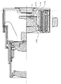
すなわち、このようなレンズ鏡胴は、図7に縦断面を示すように、CCD固体撮像素子1、ローパスフィルタ(LPF)2、固定枠3、第1の回転移動枠4、第1の直進移動枠5、第2の回転移動枠6、第2の直進移動枠7、カムリング8、第3の直進移動枠9、前飾り部品10、第1レンズ群11、第2レンズ群12、第3レンズ群13、第4レンズ群14、絞り機構を含むシャッタ装置15、退避レンズ保持枠16、保持枠回転軸17、ガイド軸18、ベース板19および固定板20を備えている。この場合、第2レンズ群12は、それを保持するレンズ保持枠を含んでいる。第3レンズ群13は、沈胴時に光軸外に退避する退避レンズ群であり、退避レンズ保持枠16によって保持されており、退避レンズ保持枠16は、保持枠回転軸17を中心として回動して第3レンズ群13を光軸上と退避位置との間で移動させる。ガイド軸18は、例えば第3レンズ群13が光軸上に位置し且つ光軸に沿って進退移動する際の退避レンズ保持枠16の位置を規制案内する。第2のレンズ群12のレンズ保持枠には、沈胴時にガイド溝18を挿通するための逃げ開口部12aが設けられており、シャッタ装置15にも、沈胴時にガイド溝18を挿通するための逃げ開口部15aが設けられている。第1レンズ群11から入射した光が、シャッタ装置15の絞り開口ではなく、第2のレンズ群12のレンズ保持枠の逃げ開口部12aとシャッタ装置15の逃げ開口部15aを通ってカムリング8の内径部8bに反射してCCD撮像素子1まで到達してしまう。
That is, such a lens barrel has a CCD solid-
この場合、図8にCCD固体撮像素子1のフィールド転送シーケンスの一例を示すように、メカニカルシャッタが閉じた後に、露光期間中にCCD固体撮像素子1に蓄積された電荷が転送されるが、この転送中にも光が入射していることになるので、撮像結果として得られる画像に、いわゆるフレアのような白みがかった模様が発生したり、CCDのフィールド転送の時間ずれにより画像中に横縞が発生することがある。
このようなレンズ保持枠等の逃げ開口部を通る有害光に対処する技術が、例えば特許文献1(特開2006−79070号)、特許文献2(特開2005−308843号)および特許文献3(実用新案登録第2565022号公報)に開示されている。特許文献1には、弾性変形可能な遮光弾性舌片をレンズ保持枠に固定し、該遮光弾性舌片を外周鏡筒の内周面と接触させることによって溝状の開口部を遮光する構成が示されている。特許文献2には、切欠開口部のあるレンズ保持枠の壁部に光軸が垂直に交わる面にほぼ平行な軸線を軸として揺動可能に遮光片を設け、沈胴状態では他のレンズ枠の突起により光軸方向にほぼ平行に退避し、撮影状態では遮光片を付勢部材によって光軸が垂直に交わる面にほぼ平行な遮光状態に復帰させる構成が示されている。特許文献3には、外周縁部に放射状に多数の切り込みを入れた薄膜遮光シートからなる遮光部材を設けることによって、摺動嵌合部の空隙開口部を遮光する構成が示されている。
In this case, as shown in an example of the field transfer sequence of the CCD solid-
For example, Patent Document 1 (Japanese Patent Laid-Open No. 2006-79070), Patent Document 2 (Japanese Patent Laid-Open No. 2005-308443), and Patent Document 3 (Japanese Patent Laid-Open No. 2005-308443) disclose techniques for coping with harmful light passing through a relief opening such as a lens holding frame. Utility Model Registration No. 2565022).
しかしながら、特許文献1〜特許文献3に示された構成は、いずれも遮光部材の撓み変形や光軸が垂直に交わる面に平行な軸を中心とする回動を利用しているため、ガイド部材に対する逃げとしてのレンズ保持枠およびシャッタ装置の逃げ開口部のような局部的な逃げ開口部を狭い部位において遮光するのには適していない。しかも、特許文献1のような構成では、弾性変形可能な部材を押圧して撓み変形させるために、耐久性に問題があり、しかもレンズ保持枠と外周鏡筒との間の相対移動に対する抵抗となってレンズ鏡胴の駆動力に影響が出てしまう。特許文献2のような構成では、沈胴状態において遮光片を光軸にほぼ平行な向きとして退避させるために遮光片の大きさがレンズ鏡筒の沈胴状態での寸法に影響し、例えば厚みに加わってしまう。特許文献3の構成を本発明のようなレンズ鏡胴に採用すると、レンズ鏡筒の沈胴状態では、常に遮光シートに負荷がかかることになり、長時間沈胴状態を維持すれば遮光シートが塑性的に変形してしまい、撮影状態における遮光に支障をきたすおそれがある。
However, all of the configurations shown in
本発明は、上述した事情に鑑みてなされたもので、狭い部位に組み込むことが可能で、耐久性にも優れた遮光構成を達成し、有害な光が撮像素子に到達するのを効果的に防止し得るレンズ鏡胴および撮像装置を提供することを目的としている。
すなわち、本発明の請求項1の目的は、多くの占有空間を必要とすることなく、簡単な構成で、有害な光が撮像素子に到達するのを効果的に防止し得て、耐久性にも優れた遮光構成を達成することを可能とするレンズ鏡胴を提供することにある。
本発明の請求項2の目的は、特に、シャッタ装置に形成された第1の逃げ開口部の開閉を効果的にしかも容易に達成し得るレンズ鏡胴を提供することにある。
本発明の請求項3の目的は、特に、シャッタ装置に近接して配置されているレンズ保持枠が存在する場合にも効果的な遮光構成を達成することを可能とするレンズ鏡胴を提供することにある。
本発明の請求項4の目的は、特に、第1の逃げ開口部の開閉を効果的にしかも容易に達成し得るレンズ鏡胴を提供することにある。
本発明の請求項5の目的は、特に、第1の逃げ開口部および第2の逃げ開口部の効果的な遮光構成を達成することを可能とするレンズ鏡胴を提供することにある。
本発明の請求項6の目的は、特に、第1の逃げ開口部、第2の逃げ開口部および第3の逃げ開口部の効果的な遮光構成を達成することを可能とするレンズ鏡胴を提供することにある。
The present invention has been made in view of the above-described circumstances, can be incorporated in a narrow part, achieves a light shielding configuration with excellent durability, and effectively prevents harmful light from reaching the image sensor. An object of the present invention is to provide a lens barrel and an imaging apparatus that can be prevented.
That is, the object of
An object of the present invention is to provide a lens barrel that can effectively and easily achieve opening and closing of the first relief opening formed in the shutter device.
The object of the third aspect of the present invention is to provide a lens barrel capable of achieving an effective light-shielding configuration even when there is a lens holding frame arranged close to the shutter device. There is.
A fourth object of the present invention is to provide a lens barrel that can effectively and easily achieve opening and closing of the first relief opening.
The object of the fifth aspect of the present invention is to provide a lens barrel capable of achieving an effective light shielding structure of the first relief opening and the second relief opening.
An object of
本発明の請求項7の目的は、特に、シャッタ機構および絞り機構による占有空間が一層狭くさらにコンパクトに構成することを可能とするレンズ鏡胴を提供することにある。
本発明の請求項8の目的は、レンズ鏡胴における多くの占有空間を必要とすることなく、簡単な構成で、有害な光が撮像素子に到達するのを効果的に防止し得て、耐久性にも優れた遮光構成を達成することを可能とする撮像装置を提供することにある。
An object of
An object of
請求項1に記載した本発明に係るレンズ鏡胴は、上述した目的を達成するために、
複数のレンズ群の少なくとも一部を沈胴させて当該複数のレンズ群を収納する沈胴状態から前記複数のレンズ群の少なくとも一部を対物側に移動することにより撮像が可能な撮影状態とするレンズ鏡胴であって、
前記複数のレンズ群を構成するレンズおよびレンズ群の少なくともいずれかを保持する少なくとも2つのレンズ保持枠と、
撮像光路を開閉するシャッタ機構を有し、前記少なくとも2つのレンズ保持枠の間に配置されたシャッタ装置と、
前記シャッタ装置の外形よりも内側の領域に設置されて、前記少なくとも2つのレンズ保持枠の1つである第1のレンズ保持枠を案内するためのガイド部材と、
前記少なくとも2つのレンズ保持枠の1つである前記シャッタ装置の対物側に近接して配置される第2のレンズ保持枠を移動させるためのカムを有するカム枠と、
を備え、
前記シャッタ装置が、前記ガイド部材を挿通可能に形成された第1の逃げ開口部を有し、
前記シャッタ装置の結像面側の光軸とほぼ垂直に交わる平面に密接し、該シャッタ装置と光軸方向について一体的に移動する遮光部材が配設され、
前記遮光部材は、平板状の遮光部が光軸とほぼ垂直に交わるように形成され、該遮光部には結像面側に向かって光軸と平行な方向に突出した突出部が形成され、該突出部の先端は前記カム枠と嵌合し
前記カム枠が回転することにより、前記遮光部が光軸を中心として回転し、前記シャッタ装置の前記第1の逃げ開口部を遮光することを特徴としている。
請求項2に記載した本発明に係るレンズ鏡胴は、請求項1のレンズ鏡胴であって、
前記遮光部材が、第2の逃げ開口部を備えることを特徴としている。
In order to achieve the above-described object, a lens barrel according to the present invention described in
A lens mirror in which at least a part of a plurality of lens groups is retracted and an imaging state in which imaging can be performed by moving at least a part of the plurality of lens groups to the objective side from a retracted state in which the plurality of lens groups are accommodated. A torso,
At least two lens holding frames that hold at least one of the lenses constituting the plurality of lens groups and the lens groups;
A shutter device having a shutter mechanism for opening and closing an imaging optical path, and disposed between the at least two lens holding frames;
A guide member for guiding a first lens holding frame, which is one of the at least two lens holding frames, installed in a region inside the outer shape of the shutter device;
A cam frame having a cam for moving a second lens holding frame disposed close to the objective side of the shutter device, which is one of the at least two lens holding frames;
With
The shutter device has a first relief opening formed so that the guide member can be inserted;
A light-shielding member that is in close contact with a plane that intersects the optical axis on the imaging plane side of the shutter device substantially perpendicularly and moves integrally with the shutter device in the optical axis direction is disposed,
The light shielding member is formed such that a flat light shielding part intersects the optical axis substantially perpendicularly, and the light shielding part is formed with a projecting part projecting in a direction parallel to the optical axis toward the imaging plane side, The tip of the projecting portion is fitted with the cam frame, and the cam frame rotates, so that the light shielding portion rotates about the optical axis and shields the first relief opening of the shutter device. It is a feature.
A lens barrel according to a second aspect of the present invention is the lens barrel according to the first aspect,
The light-shielding member includes a second relief opening.
請求項3に記載した本発明に係るレンズ鏡胴は、請求項1または請求項2のレンズ鏡胴であって、
前記第2のレンズ保持枠に、前記ガイド部材を挿通可能に形成された第3の逃げ開口部を有してなることを特徴としている。
請求項4に記載した本発明に係るレンズ鏡胴は、請求項1〜請求項3のいずれか1項のレンズ鏡胴であって、
前記遮光部材は、前記撮影状態においては前記シャッタ装置の前記第1の逃げ開口部を遮蔽し、前記撮影状態から前記沈胴状態へ移行する際に回転して、前記シャッタ装置の前記第1の逃げ開口部を開放することを特徴としている。
請求項5に記載した本発明に係るレンズ鏡胴は、請求項2〜請求項4のいずれか1項のレンズ鏡胴であって、
前記沈胴状態においては、前記第2の逃げ開口部は、前記第1の逃げ開口部に対応して位置し、
前記ガイド部材は、前記第1の逃げ開口部および前記第2の逃げ開口部に入り込むことを特徴としている。
A lens barrel according to a third aspect of the present invention is the lens barrel according to the first or second aspect,
The second lens holding frame has a third relief opening formed so that the guide member can be inserted therethrough.
A lens barrel according to a fourth aspect of the present invention is the lens barrel according to any one of the first to third aspects,
The light shielding member shields the first relief opening of the shutter device in the photographing state, and rotates when shifting from the photographing state to the retracted state, so that the first relief of the shutter device is provided. It is characterized by opening the opening.
The lens barrel according to the present invention described in
In the retracted state, the second relief opening is located corresponding to the first relief opening,
The guide member is characterized in that it enters the first escape opening and the second escape opening.
請求項6に記載した本発明に係るレンズ鏡胴は、請求項3〜請求項5のいずれか1項のレンズ鏡胴であって、
前記沈胴状態においては、前記第2の逃げ開口部は、前記第1の逃げ開口部および前記第3の逃げ開口部に対応して位置し、
前記ガイド部材は、前記第1の逃げ開口部、前記第2の逃げ開口部、および前記第3の逃げ開口部に入り込むことを特徴としている。
請求項7に記載した本発明に係るレンズ鏡胴は、請求項1〜請求項6のいずれか1項のレンズ鏡胴であって、
前記シャッタ装置は、前記撮像光路の光束を制限する絞り機構を含むことを特徴としている。
請求項8に記載した本発明に係る撮像装置は、請求項1〜請求項7のいずれか1項のレンズ鏡胴を含むことを特徴としている。
A lens barrel according to the present invention described in
In the retracted state, the second relief opening is located corresponding to the first relief opening and the third relief opening,
The guide member is characterized in that it enters the first escape opening, the second relief opening, and the third relief opening.
A lens barrel according to a seventh aspect of the present invention is the lens barrel according to any one of the first to sixth aspects,
The shutter device includes an aperture mechanism that limits a light flux in the imaging optical path.
An imaging apparatus according to an eighth aspect of the present invention includes the lens barrel according to any one of the first to seventh aspects.
本発明によれば、狭い部位に組み込むことが可能で、耐久性にも優れた遮光構成を達成し、有害な光が撮像素子に到達するのを効果的に防止し得るレンズ鏡胴および撮像装置を提供することができる。
すなわち本発明の請求項1のレンズ鏡胴によれば、
複数のレンズ群の少なくとも一部を沈胴させて当該複数のレンズ群を収納する沈胴状態から前記複数のレンズ群の少なくとも一部を対物側に移動することにより撮像が可能な撮影状態とするレンズ鏡胴であって、
前記複数のレンズ群を構成するレンズおよびレンズ群の少なくともいずれかを保持する少なくとも2つのレンズ保持枠と、
撮像光路を開閉するシャッタ機構を有し、前記少なくとも2つのレンズ保持枠の間に配置されたシャッタ装置と、
前記シャッタ装置の外形よりも内側の領域に設置されて、前記少なくとも2つのレンズ保持枠の1つである第1のレンズ保持枠を案内するためのガイド部材と、
前記少なくとも2つのレンズ保持枠の1つである前記シャッタ装置の対物側に近接して配置される第2のレンズ保持枠を移動させるためのカムを有するカム枠と、
を備え、
前記シャッタ装置が、前記ガイド部材を挿通可能に形成された第1の逃げ開口部を有し、
前記シャッタ装置の結像面側の光軸とほぼ垂直に交わる平面に密接し、該シャッタ装置と光軸方向について一体的に移動する遮光部材が配設され、
前記遮光部材は、平板状の遮光部が光軸とほぼ垂直に交わるように形成され、該遮光部には結像面側に向かって光軸と平行な方向に突出した突出部が形成され、該突出部の先端は前記カム枠と嵌合し
前記カム枠が回転することにより、前記遮光部が光軸を中心として回転し、前記シャッタ装置の前記第1の逃げ開口部を遮光することにより、多くの占有空間を必要とすることなく、簡単な構成で、有害な光が撮像素子に到達するのを効果的に防止し得て、耐久性にも優れた遮光構成を達成することが可能となる。
According to the present invention, a lens barrel and an imaging apparatus that can be incorporated in a narrow part, achieve a light shielding configuration with excellent durability, and can effectively prevent harmful light from reaching the imaging element. Can be provided.
That is, according to the lens barrel of
A lens mirror in which at least a part of a plurality of lens groups is retracted and an imaging state in which imaging can be performed by moving at least a part of the plurality of lens groups to the objective side from a retracted state in which the plurality of lens groups are accommodated. A torso,
At least two lens holding frames that hold at least one of the lenses constituting the plurality of lens groups and the lens groups;
A shutter device having a shutter mechanism for opening and closing an imaging optical path, and disposed between the at least two lens holding frames;
A guide member for guiding a first lens holding frame, which is one of the at least two lens holding frames, installed in a region inside the outer shape of the shutter device;
A cam frame having a cam for moving a second lens holding frame disposed close to the objective side of the shutter device, which is one of the at least two lens holding frames;
With
The shutter device has a first relief opening formed so that the guide member can be inserted;
A light-shielding member that is in close contact with a plane that intersects the optical axis on the imaging plane side of the shutter device substantially perpendicularly and moves integrally with the shutter device in the optical axis direction is disposed,
The light shielding member is formed such that a flat light shielding part intersects the optical axis substantially perpendicularly, and the light shielding part is formed with a projecting part projecting in a direction parallel to the optical axis toward the imaging plane side, The tip of the protrusion is fitted with the cam frame, and the cam frame rotates, so that the light shielding portion rotates about the optical axis, and the first relief opening of the shutter device is shielded from light. It is possible to effectively prevent harmful light from reaching the image sensor with a simple configuration without requiring a lot of occupied space, and it is possible to achieve a light shielding configuration with excellent durability. It becomes.
また、本発明の請求項2のレンズ鏡胴によれば、請求項1のレンズ鏡胴において、前記遮光部材に、第2の逃げ開口部を備えることにより、特に、シャッタ装置に形成された第1の逃げ開口部の開閉を効果的に且つ容易に達成することができる。
本発明の請求項3のレンズ鏡胴によれば、請求項1または請求項2のレンズ鏡胴において、第2のレンズ保持枠に、前記ガイド部材を挿通可能に形成された第3の逃げ開口部を有してなることにより、特に、シャッタ装置に近接して配置されているレンズ保持枠が存在する場合にも効果的な遮光構成を達成することが可能となる。
本発明の請求項4のレンズ鏡胴によれば、請求項1〜請求項3のいずれか1項のレンズ鏡胴において、前記遮光部材は、前記撮影状態においては前記シャッタ装置の前記第1の逃げ開口部を遮蔽し、前記撮影状態から前記沈胴状態へ移行する際に回転して、前記シャッタ装置の前記第1の逃げ開口部を開放することにより、特に、逃げ開口部の開閉を効果的にしかも容易に達成することができる。
According to the lens barrel of the second aspect of the present invention, in the lens barrel of the first aspect, the second shield opening is provided in the light shielding member. The opening and closing of one escape opening can be achieved effectively and easily.
According to the lens barrel of
According to a lens barrel of a fourth aspect of the present invention, in the lens barrel of any one of the first to third aspects, the light shielding member is the first of the shutter device in the photographing state. It is particularly effective to open and close the escape opening by shielding the escape opening and rotating when shifting from the photographing state to the retracted state to open the first relief opening of the shutter device. Moreover, it can be easily achieved.
本発明の請求項5のレンズ鏡胴によれば、請求項2〜請求項4のいずれか1項のレンズ鏡胴において、前記沈胴状態においては、前記第2の逃げ開口部は、前記第1の逃げ開口部に対応して位置し、
前記ガイド部材は、前記第1の逃げ開口部および前記第2の逃げ開口部に入り込むことにより、特に、第1の逃げ開口部および第2の逃げ開口部の効果的な遮光を実現することができる。
本発明の請求項6のレンズ鏡胴によれば、請求項1〜請求項5のいずれか1項のレンズ鏡胴において、前記沈胴状態においては、前記第2の逃げ開口部は、前記第1の逃げ開口部および前記第3の開口部に対応して位置し、
前記ガイド部材は、前記第1の逃げ開口部、前記第2の逃げ開口部、および前記第3の開口部に入り込むことにより、特に、第1の逃げ開口部、第2の開口部および第3の逃げ開口部の効果的な遮光を実現することができる。
また、本発明の請求項7のレンズ鏡胴によれば、請求項1〜請求項6のいずれか1項のレンズ鏡胴において、前記シャッタ装置は、前記撮像光路の光束を制限する絞り機構を含むことにより、特に、シャッタ機構および絞り機構による占有空間が一層狭くさらにコンパクトに構成することが可能となる。
また、本発明の請求項8の撮像装置によれば、撮像用光学系として、請求項1〜請求項7のいずれか1項のレンズ鏡胴を含むことにより、レンズ鏡胴における多くの占有空間を必要とすることなく、簡単な構成で、有害な光が撮像素子に到達するのを効果的に防止し得て、耐久性にも優れた遮光構成を達成することが可能となる。
According to the lens barrel of
In particular, the guide member can achieve effective light shielding of the first escape opening and the second escape opening by entering the first relief opening and the second relief opening. it can.
According to a lens barrel of a sixth aspect of the present invention, in the lens barrel of any one of the first to fifth aspects, in the retracted state, the second relief opening is the first barrel. Corresponding to the relief opening and the third opening,
The guide member enters the first relief opening, the second relief opening, and the third opening, and in particular, the first relief opening, the second opening, and the third It is possible to achieve effective light shielding of the relief opening.
According to a lens barrel of a seventh aspect of the present invention, in the lens barrel of any one of the first to sixth aspects, the shutter device includes a diaphragm mechanism that restricts a light flux in the imaging optical path. By including, in particular, the occupied space by the shutter mechanism and the diaphragm mechanism can be made narrower and more compact.
According to the imaging device of
以下、本発明の実施の形態に基づき、図面を参照して本発明のレンズ鏡胴を詳細に説明する。
図1〜図6は、本発明の一つの実施の形態に係る撮像装置としてのディジタルカメラに撮像用光学系として用いられるレンズ鏡胴の要部の構成を示している。図1は、望遠状態におけるレンズ鏡胴の構成を示す半縦断面図、図2は、上半部が広角状態におけるレンズ鏡胴の構成をそして下半部が沈胴状態におけるレンズ鏡胴の構成をそれぞれ示す縦断面図、図3は、上半部が中間焦点距離状態におけるレンズ鏡胴の構成をそして下半部が沈胴状態におけるレンズ鏡胴のガイド軸部分を含む構成をそれぞれ示す縦断面図、図4は、沈胴状態におけるレンズ鏡胴の遮光部材近傍の構成を示す横断面図、図5は、広角状態におけるレンズ鏡胴の遮光部材近傍の構成を示す横断面図、そして図6は、望遠状態におけるレンズ鏡胴の遮光部材近傍の構成を示す横断面図である。
Hereinafter, based on an embodiment of the present invention, a lens barrel of the present invention will be described in detail with reference to the drawings.
1 to 6 show a configuration of a main part of a lens barrel used as an imaging optical system in a digital camera as an imaging apparatus according to an embodiment of the present invention. FIG. 1 is a half longitudinal sectional view showing the configuration of the lens barrel in the telephoto state, and FIG. 2 is a configuration of the lens barrel in the wide-angle state at the upper half and the configuration of the lens barrel in the retracted state at the lower half. FIG. 3 is a longitudinal sectional view showing the configuration of the lens barrel when the upper half is in the intermediate focal length state, and FIG. 3 is a longitudinal sectional view showing the configuration including the guide shaft portion of the lens barrel when the lower half is in the retracted state. 4 is a cross-sectional view showing the configuration of the lens barrel in the vicinity of the light-shielding member in the retracted state, FIG. 5 is a cross-sectional view of the configuration in the vicinity of the light-shielding member of the lens barrel in the wide-angle state, and FIG. It is a cross-sectional view showing a configuration in the vicinity of the light blocking member of the lens barrel in the state.
図1〜図6に示すレンズ鏡胴は、図7の従来の構成と同様の部分には同符号を付して示しており、CCD固体撮像素子1、ローパスフィルタ(LPF)2、固定枠3、第1の回転移動枠4、第1の直進移動枠5、第2の回転移動枠6、第2の直進移動枠7、カムリング8、第3の直進移動枠9、前飾り部品10、第1レンズ群11、第2レンズ群12、第3レンズ群13、第4レンズ群14、絞り機構を含むシャッタ装置15、退避レンズ保持枠16、保持枠回転軸17、ガイド軸18、ベース板19、固定板20および遮光部材21を備えている。
この場合も、第2レンズ群12は、それを保持するレンズ保持枠を含んでいる。第3レンズ群13は、沈胴時に光軸外に退避する退避レンズ群であり、退避レンズ保持枠16によって保持されており、退避レンズ保持枠16は、保持枠回転軸17を中心として旋回して第3レンズ群13を光軸上と退避位置との間で移動させる。ガイド軸18は、例えば第3レンズ群13が光軸上に位置し且つ光軸に沿って進退移動する際の退避レンズ保持枠16の位置を規制案内する。第2レンズ群12のレンズ保持枠には、沈胴時にガイド溝18を挿通するための逃げ開口部12aが設けられており、シャッタ装置15にも、沈胴時にガイド溝18を挿通するための逃げ開口部15aが設けられている。
In the lens barrel shown in FIGS. 1 to 6, the same components as those in the conventional configuration shown in FIG. , First
Also in this case, the
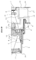
この場合、シャッタ装置15の撮像素子側に遮光部材21を設けている。遮光部材21は、図1〜図3に示すように、主体となる平板状の遮光部が光軸がほぼ垂直に交わる平面をなして形成され、シャッタ装置15の撮像素子側の光軸がほぼ垂直に交わる平面に密接して配設される。この遮光部材21の平板状の遮光部には、図2に示すように、光軸と平行な方向にアーム状に突設されたアーム部21aが形成されており、このアーム部21aの最先端は凹形状をなす凹部が形成されている。図2および図4〜図6に示すように、この凹部には、カムリング8にリブ状に突出して形成されている凸部8aが嵌合しており、カムリング8が光軸の周りで回転すると、その回転動作が凸部8aから凹部を介してアーム部21aに伝達され遮光部材21も光軸を中心として回転する構成となっている。
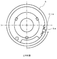
遮光部材21の遮光部は、図4〜図6に示すようにほぼ円環状に形成されており、外周縁において、シャッタ装置15の逃げ開口部15aおよび第2レンズ群(レンズ保持枠)12の逃げ開口部12aを遮蔽するとともに、周縁の一部分を切欠した形状をなして、これら逃げ開口部15aおよび12aを開放する逃げ開口部21bが形成されている。
In this case, the
The light shielding portion of the
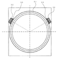
撮影状態では、図5および図6にそれぞれ広角状態と望遠状態を示すように、遮光部材21の遮光部の周縁が、シャッタ装置15の逃げ開口部15aおよび第2レンズ保持枠(第2レンズ群)12の逃げ開口部12aを遮蔽している。これらのような撮影状態から図4に示すような沈胴状態に移動する際に遮光部材21が回転して、その逃げ開口部21bが逃げ開口部15aおよび12aに対応して位置するようになるので、ガイド軸18は、遮光部材21の逃げ開口部21bを通してシャッタ装置15と第2レンズ保持枠12の逃げ開口部15aおよび12aに入り込み、沈胴状態に移行することが可能となる。
これによって、第1レンズ群11から入射した光がシャッタ装置15の絞り開口以外の部分からCCD固体撮像素子1へ到達するのを防止することが可能となる。またこの実施の形態においては、シャッタ装置15と遮光部材21とが、光軸方向について一体的に移動することを可能とするために、図4〜図6に示すようにシャッタ装置15に爪状の係合爪15bが円周上にほぼ等間隔に3箇所設けられている。なお、明確には図示していないが、遮光部材には、シャッタ装置15に遮光部材21を組み付ける位置において、係合爪15bを逃げる切欠部が形成されている。
In the photographing state, as shown in FIGS. 5 and 6, respectively, the wide-angle state and the telephoto state, the periphery of the light-shielding portion of the light-shielding
This makes it possible to prevent light incident from the
したがって、このような構成により、第1レンズ群11から入射した光が、第2のレンズ群12のレンズ保持枠の逃げ開口部12aとシャッタ装置15の逃げ開口部15aのような、シャッタ装置15の絞り開口以外の部位を通って、カムリング8の内径部8bに反射してCCD撮像素子1まで到達してしまうのを防止することが可能なレンズ鏡胴を達成することができる。なお、上述においては本発明によるレンズ鏡胴を用いて撮像装置としてのディジタルカメラを構成したものとして説明したが、カメラ機能を備えた携帯情報端末のような他の撮像装置に本発明を適用しても良い。
次に、本発明に関連する他の実施の形態に係るレンズ鏡胴について、図面を参照して詳細に説明する。
ディジタルカメラ等の撮像装置は、撮像素子と、撮像素子に結像するための複数のレンズおよび複数のレンズを所定の位置に移動させるためのレンズ駆動装置を含むレンズ鏡胴とを備えている。近年、コンパクトカメラ等においては、回転して光軸方向に進退する1つ以上の回転筒と、回転せずに光軸方向に進退する1つ以上の直進ガイド筒と、回転せずにレンズを保持して光軸方向に進退する1つ以上のレンズ保持筒とを有して構成され、非使用時には短く収納され、使用時には光軸方向に伸長し、各レンズを所定の位置に保持して所定の焦点距離とするレンズ鏡胴が数多く用いられている。
Therefore, with such a configuration, the light incident from the
Next, a lens barrel according to another embodiment related to the present invention will be described in detail with reference to the drawings.
An imaging apparatus such as a digital camera includes an imaging element, and a lens barrel including a plurality of lenses for forming an image on the imaging element and a lens driving device for moving the plurality of lenses to a predetermined position. In recent years, in compact cameras and the like, one or more rotating cylinders that rotate to advance and retract in the optical axis direction, one or more rectilinear guide cylinders that advance and retract in the optical axis direction without rotating, and a lens without rotating One or more lens holding cylinders that hold and advance and retract in the direction of the optical axis, are stored short when not in use, extend in the direction of the optical axis when in use, and hold each lens in place. Many lens barrels having a predetermined focal length are used.
また、小型化が進むことによって、レンズの光軸合わせにより高い精度が必要とされる傾向にある。精度を高くするためには、レンズ保持枠とレンズとの精度だけではなく、レンズ保持枠を駆動する回転筒の光軸位置ずれについても高精度に保つ必要がある。回転筒は、相対移動する対象物との空隙、つまりクリアランスをもつことによって移動することが可能となるのであり、精度を高めるためにこのクリアランスを狭めてしまうと、作動不良や余計なエネルギロスを発生させてしまう。さらに、カメラとして電源をオンとしたときにすぐに撮影状態に入るためには、鏡胴が収納状態から撮影状態まで高速で移動する必要があり、クリアランスを狭めてしまうと、摩擦抵抗が増大し、高速で移動することが困難となってしまう。
このようなレンズの光軸ぶれを解決するために、補助レンズの脱着の保持に磁石を使用しているものがある。また、レンズ保持枠に磁石を設け、レンズ保持枠を光軸方向に移動可能として保持している案内手段に設けられているモータの金属ハウジングに磁石の吸引力を作用させ、光軸と交差する方向に振れるのを防止して作動を滑らかにすることも考えられている。しかしながら、この方法では、常にレンズ保持枠が付勢されレンズ光軸を合わせる必要がない箇所においてもエネルギを必要としてしまう。また、この方法は、レンズ保持枠が回転する場合には、1箇所の磁石で力を受けているためにガタを効果的に取り切ることはできない。
Further, with the progress of miniaturization, there is a tendency that high accuracy is required for optical axis alignment of lenses. In order to increase the accuracy, it is necessary to maintain not only the accuracy between the lens holding frame and the lens but also the optical axis position shift of the rotating cylinder that drives the lens holding frame with high accuracy. The rotating cylinder can move by having a clearance with the relative moving object, that is, a clearance, and if this clearance is narrowed to increase accuracy, malfunctions and extra energy loss may occur. It will be generated. Furthermore, in order to immediately enter the shooting state when the camera is turned on, it is necessary to move the lens barrel from the retracted state to the shooting state at high speed. If the clearance is narrowed, the frictional resistance increases. It becomes difficult to move at high speed.
In order to solve such an optical axis shake of the lens, there is a type that uses a magnet to hold the auxiliary lens attached and detached. Further, a magnet is provided on the lens holding frame, and the magnet's attractive force is applied to the metal housing of the motor provided in the guide means that holds the lens holding frame so as to be movable in the direction of the optical axis, thereby intersecting the optical axis. It is also considered to prevent the movement in the direction and smooth the operation. However, with this method, energy is required even at locations where the lens holding frame is always urged and the lens optical axis does not need to be aligned. Also, this method cannot effectively remove the backlash when the lens holding frame rotates because it receives a force from one magnet.
そこで、撮影状態において磁力の吸引力により回転筒が付勢されるようにして、撮影状態では光軸を精度良く合わせることを可能とし、非撮影状態での作動では磁力の吸引力がなくなるようにして、作動におけるエネルギのロスを効果的に防ぐことを可能とするのが、この実施の形態に係るレンズ鏡胴である。
すなわち、この実施の形態に係る第1の態様としてのレンズ鏡胴は、
撮像面に結像することで撮影できるレンズ群と、
前記レンズ群の少なくとも一つを保持する1つ以上のレンズ保持枠と、
前記レンズ保持枠を保持し且つ回転することで前記レンズ保持枠を光軸方向の所定位置に移動することが可能なレンズ駆動筒と、
前記レンズ群、前記レンズ保持枠および前記レンズ駆動筒を保持する固定筒とを備えてなり、
前記レンズ駆動筒は、回転して前記レンズ保持枠を進退可能にする1つ以上の回転筒を有するレンズ鏡胴において、
前記固定筒に保持されている前記回転筒の後方部に磁性体を備え、前記固定筒の前方部に少なくとも2箇所の磁力を発生させる部材を設け、前記磁力を発生させる部材の付近には前記回転筒が磁力により付勢される付勢面を形成するようにして、
前記回転筒が前方に移動したときに光軸方向とは垂直な方向に前記磁性体に吸引力を発生し、吸引力により前記回転筒が付勢面に付勢されたときには、撮像面の中心軸と回転筒の中心軸が一致するように構成することを特徴としている。
Therefore, the rotating cylinder is urged by the magnetic attractive force in the photographing state, so that the optical axis can be accurately aligned in the photographing state, and the magnetic attractive force is lost in the operation in the non-photographing state. Thus, it is the lens barrel according to this embodiment that makes it possible to effectively prevent energy loss during operation.
That is, the lens barrel as the first aspect according to this embodiment is
A lens group that can be photographed by forming an image on the imaging surface;
One or more lens holding frames for holding at least one of the lens groups;
A lens driving cylinder capable of moving the lens holding frame to a predetermined position in the optical axis direction by holding and rotating the lens holding frame;
The lens group, the lens holding frame, and a fixed cylinder that holds the lens driving cylinder,
In the lens barrel having one or more rotating cylinders that rotate to enable the lens holding frame to move forward and backward,
A magnetic body is provided in a rear part of the rotating cylinder held by the fixed cylinder, a member for generating at least two magnetic forces is provided in a front part of the fixed cylinder, and the member for generating the magnetic force is provided near the member for generating the magnetic force. The rotating cylinder forms a biasing surface that is biased by magnetic force,
When the rotating cylinder moves forward, an attractive force is generated on the magnetic body in a direction perpendicular to the optical axis direction, and when the rotating cylinder is urged against the urging surface by the attractive force, the center of the imaging surface It is characterized in that the shaft and the central axis of the rotating cylinder coincide with each other.
この第1の態様のレンズ鏡胴は、回転筒が前方に移動したときにのみ、磁力により吸引力が発生し、回転筒が付勢面に付勢されることで光軸合わせをするものである。
この実施の形態に係る第2の態様としてのレンズ鏡胴は、前記第1の態様に従ったレンズ鏡胴において、
前記回転筒はレンズ鏡胴が短縮位置から撮影領域前までは、回転しながら光軸方向に移動することができ、撮影領域では回転のみを行い、そして前記磁性体と磁力を発生させる部材とによる吸引力は撮影領域で最大となるように配置されていることを特徴としている。
この第2の態様のレンズ鏡胴は、光軸合わせが必要な撮影領域では、磁力による吸引力が発生し、光軸合わせの必要がない短縮位置と撮影領域との間では、磁力による吸引力が作用しないようにして、回転筒を回転させるためのエネルギのロスを少なくするものである。
The lens barrel of the first aspect performs optical axis alignment by generating an attractive force by magnetic force only when the rotating cylinder moves forward, and the rotating cylinder is urged by the urging surface. is there.
The lens barrel as a second aspect according to this embodiment is the lens barrel according to the first aspect,
The rotating barrel can move in the direction of the optical axis while rotating from the shortened position to the front of the shooting area, and only rotates in the shooting area, and depends on the magnetic body and the member that generates magnetic force. It is characterized by being arranged so that the suction force is maximized in the imaging region.
The lens barrel of the second aspect generates an attractive force due to magnetic force in an imaging region where optical axis alignment is required, and an attractive force due to magnetic force between a shortened position where no optical axis alignment is necessary and the imaging region. Prevents the loss of energy for rotating the rotating cylinder.
この実施の形態に係る第3の態様としてのレンズ鏡胴は、前記第1の態様または第2の態様に従ったレンズ鏡胴において、
前記磁力を発生させる部材が、磁石から構成されることを特徴としている。
この第3の態様のレンズ鏡胴は、安価な部材により高精度な光軸合わせを行うことを可能とするものである。
この実施の形態に係る第4の態様としてのレンズ鏡胴は、前記第1の態様または第2の態様に従ったレンズ鏡胴において、
前記磁力を発生させる部材が、電磁石から構成されることを特徴としている。
A lens barrel as a third aspect according to this embodiment is the lens barrel according to the first aspect or the second aspect.
The member that generates the magnetic force is composed of a magnet.
The lens barrel of the third aspect makes it possible to perform optical axis alignment with high accuracy using an inexpensive member.
A lens barrel as a fourth aspect according to this embodiment is the lens barrel according to the first aspect or the second aspect.
The member for generating the magnetic force is composed of an electromagnet.
この第4の態様のレンズ鏡胴は、必要なときだけ光軸合わせをするという制御を簡単に行うことができ、光軸合わせが不要である時のエネルギロスを抑制することを可能とするものである。 The lens barrel according to the fourth aspect can easily perform the control of aligning the optical axis only when necessary, and can suppress energy loss when the optical axis alignment is unnecessary. It is.
この実施の形態に係る第5の態様としてのレンズ鏡胴は、前記第4の態様に従ったレンズ鏡胴において、
撮像時のみ通電して磁力を発生させることを特徴としている。
この第5の態様のレンズ鏡胴は、撮影状態のみ光軸合わせを行い、その他の状態では回転筒にガタを持たせることによって作動上のエネルギロスを抑制することを可能とするものである。
この実施の形態に係る第6の態様としてのカメラ等の撮像装置は、前記第1の態様〜第5の態様のいずれか一つに従ったレンズ鏡胴を備えることを特徴としている。
この第6の態様の撮像装置は、高画質を得ることができて、エネルギロスを抑制することを可能とするものである。
次に上述した本発明に関連する他の実施の形態に係るレンズ鏡胴の具体的な実施の形態を詳細に説明する。
The lens barrel as a fifth aspect according to this embodiment is the lens barrel according to the fourth aspect,
It is characterized in that it is energized only during imaging to generate a magnetic force.
In the lens barrel of the fifth aspect, the optical axis is aligned only in the photographing state, and in other states, it is possible to suppress the energy loss in operation by giving the rotating cylinder backlash.
An imaging apparatus such as a camera as a sixth aspect according to this embodiment includes a lens barrel according to any one of the first to fifth aspects.
The image pickup apparatus according to the sixth aspect can obtain high image quality and suppress energy loss.
Next, specific embodiments of the lens barrel according to another embodiment related to the present invention will be described in detail.
図9〜図16は、撮像装置としてのディジタルカメラに撮像用光学系として用いられるレンズ鏡胴の要部の構成を示している。図9は、上半部が鏡胴が伸長していて電磁石を付勢した撮像状態におけるレンズ鏡胴の構成をそして下半部が収納状態におけるレンズ鏡胴の構成をそれぞれ示す縦断面図、図10は、図9の要部の詳細図、図11は、鏡胴が伸長していて電磁石を消勢した非撮像状態におけるレンズ鏡胴の構成を示す縦断面図、図12は、図11の要部の詳細図、図13は、収納途中におけるレンズ鏡胴の構成を示す縦断面図、図14は、レンズ鏡胴の要部である第1の回転移動枠と固定枠を説明するための分解斜視図、図15は、電磁石付勢時における第1の回転移動枠と電磁石の配置関係を示す模式的横断面図、そして図16は、電磁石消勢時における第1の回転移動枠と電磁石の配置関係を示す模式的横断面図である。
図9〜図16に示すレンズ鏡胴は、図1の構成と同様の部分には同符号を付して示しており、CCD固体撮像素子1、ローパスフィルタ(LPF)2、固定枠3、第1の回転移動枠4、第1の直進移動枠5、第2の回転移動枠6、第2の直進移動枠7、カムリング8、第3の直進移動枠9、前飾り部品10、第1レンズ群11、第2レンズ群12、第3レンズ群13、第4レンズ群14、絞り機構を含むシャッタ装置15、係合ピン30、磁性体リング31、電磁石32および当接部材33を備えている。
9 to 16 show the configuration of the main part of a lens barrel used as an imaging optical system in a digital camera as an imaging apparatus. FIG. 9 is a longitudinal sectional view showing the configuration of the lens barrel in an imaging state in which the upper half is extended and the electromagnet is energized, and the lower half is a configuration of the lens barrel in the retracted state. 10 is a detailed view of the main part of FIG. 9, FIG. 11 is a longitudinal sectional view showing the configuration of the lens barrel in a non-imaging state in which the lens barrel is extended and the electromagnet is de-energized, and FIG. FIG. 13 is a longitudinal sectional view showing the configuration of the lens barrel in the middle of storage, and FIG. 14 is a diagram for explaining the first rotation moving frame and the fixed frame, which are the main parts of the lens barrel. FIG. 15 is an exploded perspective view, FIG. 15 is a schematic cross-sectional view showing the positional relationship between the first rotary moving frame and the electromagnet when the electromagnet is energized, and FIG. 16 is the first rotary moving frame and the electromagnet when the electromagnet is deenergized. It is a typical cross-sectional view which shows the arrangement | positioning relationship.
In the lens barrel shown in FIGS. 9 to 16, the same components as those in FIG. 1 are denoted by the same reference numerals, and a CCD solid-
図9〜図16に示す実施の形態における基本的な構成は、第1レンズ群11が第1レンズ保持枠と一体化された第3の直進移動枠9に保持されており、第3の直進移動枠9は、第2の回転移動枠6の内周面に設けられているカム溝に係合している第3の直進移動枠9のカムフォロワ9aを介して第2の回転移動枠6により保持されている。第3の直進移動枠9の内周面には、第2の直進移動枠7が相対的に直進移動可能として溝嵌合しており、第2の直進移動枠7は、第2の回転移動枠6と相対的に回転可能で且つ光軸方向に一体に移動できるように、光軸方向とは垂直な面で第2の回転移動枠6のキー溝6aと第2の直進移動枠7のキー部7aとが係合している。このことによって、第3の直進移動枠9は、第2の回転移動枠6が回転すると、第2の回転移動枠6の内周面に設けられたカム溝に沿って移動することができる。第2の回転移動枠6は、そのヘリコイド6bによって第1の直進移動枠5の内周面に設けられたヘリコイド5bに嵌合しており、第2の直進移動枠7は、光軸方向に沿って直進移動することができるように、第2の直進移動枠7の直進キー部7bが第1の直進移動枠5の内周面に設けられている直進ガイド溝5bに嵌合している。
The basic configuration in the embodiment shown in FIGS. 9 to 16 is that the
第1の回転移動枠4は、第2の回転移動枠6と一体的に回転できるように係合ピン30で係合され、第1の直進移動枠5とは、光軸方向には一体的に移動し相対回転可能となるように、光軸方向とは垂直な面で第1の回転移動枠4のキー溝4aが第1の直進移動枠6のキー部6aに係合している。このことで、第1の回転移動枠4が回転することによって、第2の回転移動枠6は、第1の直進移動枠5の内径に設けられたヘリコイドに沿って回転しながら進退し、第2の直進移動枠7は、第2の回転移動枠6と光軸方向に一体的に回転せずに、直進することを可能としている。第1の回転移動枠4は、CCD撮像素子1を保持している固定枠3の内周面にヘリコイド嵌合し、第1の直進移動枠6は、直進キー部6bと固定枠3の内周面に光軸方向に沿って設けられた直進ガイド溝3aと係合している。固定枠3には、第1の回転移動枠4を駆動するモータおよび複数のギヤが備えられており、第1の回転移動枠4と係合している。このことにより、モータから受けた回転力がギヤを介して第1の回転移動枠4を回転させ、第1の直進移動枠5、第2の回転移動枠6および第2の直進移動枠7を介して第1レンズ群11を保持する第3の直進移動枠9を光軸方向に進退させることが可能となる。
第3レンズ群13および第4レンズ群14は、固定枠3に設けられた保持枠回転軸17およびガイド軸18により保持されており、保持枠回転軸17を中心に旋回動作するとともにガイド軸18に沿って光軸方向に進退動作することを可能としている。
The first
The
第1の回転移動枠4および第1の直進移動枠5は、固定枠3に対して光軸方向に進退するために第1の回転移動枠4のヘリコイド最外径部と第1の直進移動枠5の直進キー部は一定以上のクリアランスをもっている。このクリアランスにより回転移動枠の回転および直進運動をエネルギロスなく行うことを可能としている。
この場合、第1の回転移動枠4の基端部には、磁性体のリング部材31が設けられており、固定枠3には、第1の回転移動枠4が撮影領域まで繰出した時に第1の回転移動枠4のリング部材31と対向し且つ光軸方向を中心にほぼ120°の角度間隔を存した位置に2つの電磁石32を備えている。電磁石32が付勢されると、回転移動枠4のリング部材31と電磁石32との間に電磁力が働いてリング部材31との間に吸引力が作用する。このとき、回転移動枠4のリング部材31と2つの電磁石32との間には、電磁石側に当接される2つの当接部材33がそれぞれ設けられている。このとき電磁石32が付勢され、当接部材33を介して吸着された状態では、第1の回転移動枠4の中心軸が、第3レンズ群13および第4レンズ群14の光軸と一致するように当接部材33を配置する。
The first
In this case, a magnetic ring member 31 is provided at the base end portion of the first
電磁石32は、例えば撮像装置としてのカメラに設けられたレリーズボタンが押されたと同時に通電されて付勢され、励磁される。この磁力により第1の回転移動枠4のリング部材31に吸引力が作用し、第1の回転移動枠4は当接部材33を挟んで電磁石32側に付勢されて、第1の回転移動枠4の中心軸が、第3レンズ群13および第4レンズ群14の光軸と一致する。これにより、撮影時には光軸が一致し高性能な像性能を得ることが可能となる。一方、第1の回転移動枠4を回転し、ズーミングおよび収納(もしくは起動)するときは、電磁石32には通電されず第1の回転移動枠4はクリアランスを保つため、摩擦によるエネルギロスなく駆動することが可能となる。
以上より、第1の回転移動枠4が撮影状態にあるときに電磁石32の磁力に基づく吸引力によって電磁石32側に押圧されることで、撮影状態では光軸を精度良く合わせることができ、非撮影状態では、電磁石32が消勢されて磁力による吸引力がなくなるため、作動のエネルギロスを防ぐことができる。
次に、本発明に関連するその他の実施の形態に係るレンズ鏡胴について、図面を参照して詳細に説明する。
The
As described above, when the first
Next, lens barrels according to other embodiments related to the present invention will be described in detail with reference to the drawings.
ディジタルカメラ等の撮像装置においては、焦点距離変更可能なズームレンズ等の撮影レンズの高性能化およびユーザの要求による小型化等の進展に伴い、振動対策等のためにレンズ鏡筒に緩衝部材を設けたものがある。しかしながら、この場合、鏡枠と鏡枠保護部材の2重構造となるため形状が大きくなるという問題があった。また外力等が加わった場合に、緩衝部材が移動するような構造を取るため、鏡枠保護部材と緩衝部材の取り付けが大変困難であった。
一方、撮影可能状態にある繰り出したレンズ鏡胴を、撮影者が無意識に押圧してレンズ鏡胴を収納側へ移動させてしまい、レンズ鏡胴が破損してしまうことがあった。また、不意にレンズ鏡胴に振動が加わってピント不良が発生したまま撮影してしまうこともあった。
このような問題に対して、レンズ鏡胴の破損等を防止することが可能で、しかも組立てが容易なレンズ制御装置および撮像装置を提供するのがこの実施の形態である。また、この実施の形態によるレンズ制御装置および撮像装置においては、振動等によるピント不良が発生した場合にも自動的に復帰することをも可能とする。
In an imaging device such as a digital camera, a buffer member is provided on a lens barrel as a countermeasure against vibration as the performance of a photographing lens such as a zoom lens capable of changing a focal length is improved and the size is reduced according to user requirements. There is something provided. However, in this case, there is a problem that the shape becomes large because of the double structure of the lens frame and the lens frame protection member. Further, since the buffer member moves so as to move when an external force or the like is applied, it is very difficult to attach the lens frame protection member and the buffer member.
On the other hand, there is a case where the photographer unconsciously presses the extended lens barrel in the photographing enabled state to move the lens barrel to the storage side, and the lens barrel is damaged. In addition, the lens barrel may be unexpectedly vibrated, resulting in shooting with a focus failure.
This embodiment provides a lens control device and an imaging device that can prevent the lens barrel from being damaged and that can be easily assembled. In addition, the lens control device and the imaging device according to this embodiment can automatically return even when a focus failure due to vibration or the like occurs.
すなわち、この実施の形態に係る第1の態様としてのレンズ制御装置は、
レンズおよび鏡胴枠を駆動させるための駆動源として直流モータを備えたレンズ鏡胴を制御するためのレンズ制御装置において、
前記直流モータを停止させる際にショートブレーキ制御を行い、その後も通電オフせずにショートブレーキ制御を継続することを特徴としている。
この実施の形態に係る第2の態様としてのレンズ制御装置は、
レンズおよび鏡胴枠を駆動させるための駆動源として、直流モータ、前記直流モータの回転を検出するための光検出器および遮光部材を備えたレンズ鏡胴と、中央演算処理装置と、モータ制御駆動手段とを備えたレンズ制御装置において、
前記中央演算処理装置からの直流モータ駆動命令なしに前記検出器が前記直流モータの回転を検出すると、ある一定時間ショートブレーキ制御を行うことを特徴としている。
この実施の形態に係る第3の態様としてのレンズ制御装置は、
レンズおよび鏡胴枠を駆動させるための駆動源として、直流モータ、前記直流モータの回転を検出するための光検出器および遮光部材を備えたレンズ鏡胴と、中央演算処理装置と、モータ制御駆動手段とを備えたレンズ制御装置において、
前記中央演算処理装置からの直流モータ駆動命令なしに前記検出器が前記直流モータの回転を検出すると、ある一定時間前記直流モータにショートブレーキ制御を行った後に前記レンズ鏡胴をリセット動作させることを特徴としている。
That is, the lens control device as the first aspect according to this embodiment is
In a lens control device for controlling a lens barrel provided with a DC motor as a drive source for driving the lens and the lens barrel frame,
Short brake control is performed when the DC motor is stopped, and the short brake control is continued without turning off the power thereafter.
The lens control device as the second aspect according to this embodiment is
As a drive source for driving the lens and lens barrel frame, a direct current motor, a lens barrel provided with a photodetector and a light shielding member for detecting rotation of the direct current motor, a central processing unit, a motor control drive A lens control device comprising:
When the detector detects the rotation of the DC motor without a DC motor drive command from the central processing unit, short brake control is performed for a certain period of time.
The lens control device as the third aspect according to this embodiment is
As a drive source for driving the lens and lens barrel frame, a direct current motor, a lens barrel provided with a photodetector and a light shielding member for detecting rotation of the direct current motor, a central processing unit, a motor control drive A lens control device comprising:
When the detector detects the rotation of the DC motor without a DC motor drive command from the central processing unit, the lens barrel is reset after performing a short brake control on the DC motor for a certain period of time. It is a feature.
この実施の形態に係る第4の態様としてのカメラ等の撮像装置は、
レンズおよび鏡胴枠を駆動させるための駆動源として、直流モータ、前記直流モータの回転を検出するための光検出器および遮光部材を備えたレンズ鏡胴と、中央演算処理装置と、モータ制御駆動手段と、ブレ量を検出するためのブレ検出手段とを備えた撮像装置において、
前記ブレ検出手段が、あるしきい値よりも大きい値を検出すると、ある一定時間前記直流モータにショートブレーキ制御を行うことを特徴としている。
この実施の形態に係る第5の態様としてのカメラ等の撮像装置は、
レンズおよび鏡胴枠を駆動させるための駆動源として、直流モータ、前記直流モータの回転を検出するための光検出器および遮光部材を備えたレンズ鏡胴と、中央演算処理装置と、モータ制御駆動手段と、ブレ量を検出するためのブレ検出手段とを備えた撮像装置において、
前記ブレ検出手段が、あるしきい値よりも大きい値を検出すると、ある一定時間前記直流モータにショートブレーキ制御を行った後に前記レンズ鏡胴をリセット動作させることを特徴としている。
このようなレンズ制御装置および撮像装置は、コストアップを招くことなく、撮影者が不用意に手で押圧してしまっても破損を防止することが可能となる。
An imaging apparatus such as a camera as a fourth aspect according to this embodiment is
As a drive source for driving the lens and lens barrel frame, a direct current motor, a lens barrel provided with a photodetector and a light shielding member for detecting rotation of the direct current motor, a central processing unit, a motor control drive In an imaging device comprising means and a shake detection means for detecting a shake amount,
When the shake detecting means detects a value larger than a certain threshold value, the DC motor is short brake controlled for a certain period of time.
An imaging apparatus such as a camera as a fifth aspect according to this embodiment
As a drive source for driving the lens and lens barrel frame, a direct current motor, a lens barrel provided with a photodetector and a light shielding member for detecting rotation of the direct current motor, a central processing unit, a motor control drive In an imaging device comprising means and a shake detection means for detecting a shake amount,
When the blur detecting means detects a value larger than a certain threshold value, the lens barrel is reset after performing a short brake control on the DC motor for a certain period of time.
Such a lens control device and an imaging device can prevent damage without incurring a cost increase even if the photographer carelessly presses it with his hand.
次に上述した本発明に関連するその他の実施の形態に係るレンズ制御装置の具体的な実施の形態を詳細に説明する。
すなわち、この本発明に関連するその他の実施の形態に係るレンズ制御装置の第1の構成を図17に示している。図17においてレンズ制御装置は、レンズ鏡胴50、中央演算処理装置61およびモータ駆動手段62を具備している。レンズ鏡胴50は、直流モータ51、レンズ駆動手段52および検出装置53を備えている。
レンズ鏡胴50は、レンズ等を駆動させるための駆動源として直流モータ51を備え、レンズ駆動手段52として、ギヤ機構を介して鏡胴枠およびレンズを駆動すべく構成されている。
例えば、最も被写体側へ繰り出した撮影可能状態、例えば、望遠側の撮影状態において、撮影者が無意識にレンズ鏡胴50を手で押圧してしまった場合、鏡胴のカム傾斜により鏡胴枠からギヤ機構を介して直流モータ51まで回転力が伝わり、直流モータ51が回転してしまって、鏡胴枠が収納側へ移動してしまうことがある。
Next, specific embodiments of the lens control device according to other embodiments related to the present invention will be described in detail.
That is, FIG. 17 shows a first configuration of a lens control device according to another embodiment related to the present invention. In FIG. 17, the lens control device includes a
The
For example, when the photographer unintentionally presses the
そこで、直流モータ51が、若干量回転すると直流モータ51の出力軸に設置された遮光手段とこれを検出するための光検出器からなるモータ回転検出手段である検出装置53により直流モータの回転を検出することが可能である。これによって、モータ51の回転を検出すると中央演算処理装置(CPU)61から直流モータ51を、ショートブレーキさせる命令が出され、モータ駆動手段62は直流モータ51の端子間をショートさせることができる。直流モータ51の端子間がフリーである状態とショートされている状態では明らかにショートされている状態の方が直流モータ51を回転させるためのトルクが大きくなることは直流モータ51の構成より明らかである。
このことにより、直流モータ51の回転検出手段が回転を検出すると瞬時にモータ51の端子間がショートされて鏡胴が収納側へ移動するに必要な力量が上昇して収納側へ移動することを自動的に防ぐことが可能とになる。このようにして鏡胴が破損することを防止することが可能となる。また、手で少し押されたりした場合には、ピント位置もずれてしまうため、直流モータ51のショートブレーキ後、レンズ鏡胴50を正規の位置に戻すためリセット動作を行うことによりピント不良の発生も防ぐことが可能になる。
Therefore, when the direct current motor 51 is rotated a little, the direct current motor is rotated by a
As a result, when the rotation detection means of the DC motor 51 detects rotation, the terminals of the motor 51 are instantaneously short-circuited, increasing the amount of force required to move the lens barrel to the storage side and moving to the storage side. It becomes possible to prevent automatically. In this way, it is possible to prevent the lens barrel from being damaged. Further, when the hand is pushed a little, the focus position is also shifted. Therefore, after a short brake of the DC motor 51, a focus failure occurs by performing a reset operation to return the
また、この本発明に関連するその他の実施の形態に係るレンズ制御装置の第2の構成を図18に示している。図18においてレンズ制御装置は、図17と同様の部分には同符号を付して示しており、レンズ鏡胴50、中央演算処理装置61、モータ駆動手段62に加えて手ぶれ等のぶれを検出するためのぶれ検出手段71を具備している。レンズ鏡胴50は、この場合も直流モータ51、レンズ駆動手段52および検出装置53を備えている。
FIG. 18 shows a second configuration of the lens control apparatus according to another embodiment related to the present invention. In FIG. 18, the same components as those in FIG. 17 are denoted by the same reference numerals as those in FIG. 17, and in addition to the
図18のように、手ぶれ等のぶれ補正を行う撮像装置においては、ぶれ量を検出するためのぶれ検出手段71を備えている。通常のぶれ量と衝撃等が加わった場合のぶれ検出手段71の出力値には大きな差が発生するので、あるしきい値以上であればぶれと判断せずに衝撃が加わったと判断することが可能である。レンズ鏡胴50に衝撃が加わるとピント不良が発生する可能性が高いので、ぶれ検出手段71があるしきい値以上であることを検出した場合も直流モータ51の端子間をショートさせることで鏡胴枠の移動を防止することが可能になり、その後レンズ鏡胴50をリセット動作させることでピント不良を回避することが可能になる。
As shown in FIG. 18, an imaging apparatus that performs camera shake correction such as camera shake includes a camera shake detection unit 71 for detecting a camera shake amount. Since there is a large difference in the output value of the shake detection means 71 when a normal shake amount and a shock are applied, it is possible to determine that a shock has been applied without determining a shake if it exceeds a certain threshold value. Is possible. When an impact is applied to the
1 CCD固体撮像素子
2 ローパスフィルタ(LPF)
3 固定枠
4 第1の回転移動枠
5 第1の直進移動枠
6 第2の回転移動枠
7 第2の直進移動枠
8 カムリング
9 第3の直進移動枠
10 前飾り部品
11 第1レンズ群
12 第2レンズ群
13 第3レンズ群
14 第4レンズ群
15 絞り機構を含むシャッタ装置
16 退避レンズ保持枠
17 保持枠回転軸
18 ガイド軸
19 ベース板
20 固定板
21 遮光部材
1 CCD solid-
DESCRIPTION OF
Claims (8)
前記複数のレンズ群を構成するレンズおよびレンズ群の少なくともいずれかを保持する少なくとも2つのレンズ保持枠と、
撮像光路を開閉するシャッタ機構を有し、前記少なくとも2つのレンズ保持枠の間に配置されたシャッタ装置と、
前記シャッタ装置の外形よりも内側の領域に設置されて、前記少なくとも2つのレンズ保持枠の1つである第1のレンズ保持枠を案内するためのガイド部材と、
前記少なくとも2つのレンズ保持枠の1つである前記シャッタ装置の対物側に近接して配置される第2のレンズ保持枠を移動させるためのカムを有するカム枠と、
を備え、
前記シャッタ装置が、前記ガイド部材を挿通可能に形成された第1の逃げ開口部を有し、
前記シャッタ装置の結像面側の光軸とほぼ垂直に交わる平面に密接し、該シャッタ装置と光軸方向について一体的に移動する遮光部材が配設され、
前記遮光部材は、平板状の遮光部が光軸とほぼ垂直に交わるように形成され、該遮光部には結像面側に向かって光軸と平行な方向に突出した突出部が形成され、該突出部の先端は前記カム枠と嵌合し
前記カム枠が回転することにより、前記遮光部が光軸を中心として回転し、前記シャッタ装置の前記第1の逃げ開口部を遮光することを特徴とするレンズ鏡胴。 A lens mirror in which at least a part of a plurality of lens groups is retracted and an imaging state in which imaging can be performed by moving at least a part of the plurality of lens groups to the objective side from a retracted state in which the plurality of lens groups are accommodated. A torso,
At least two lens holding frames that hold at least one of the lenses constituting the plurality of lens groups and the lens groups;
A shutter device having a shutter mechanism for opening and closing an imaging optical path, and disposed between the at least two lens holding frames;
A guide member for guiding a first lens holding frame, which is one of the at least two lens holding frames, installed in a region inside the outer shape of the shutter device;
A cam frame having a cam for moving a second lens holding frame disposed close to the objective side of the shutter device, which is one of the at least two lens holding frames;
With
The shutter device has a first relief opening formed so that the guide member can be inserted;
A light-shielding member that is in close contact with a plane that intersects the optical axis on the imaging plane side of the shutter device substantially perpendicularly and moves integrally with the shutter device in the optical axis direction is disposed,
The light shielding member is formed such that a flat light shielding part intersects the optical axis substantially perpendicularly, and the light shielding part is formed with a projecting part projecting in a direction parallel to the optical axis toward the imaging plane side, The tip of the projecting portion is fitted with the cam frame, and the cam frame rotates, so that the light shielding portion rotates about the optical axis and shields the first relief opening of the shutter device. Characteristic lens barrel.
前記ガイド部材は、前記第1の逃げ開口部および前記第2の逃げ開口部に入り込むことを特徴とする請求項2〜請求項4のいずれか1項に記載のレンズ鏡胴。 In the retracted state, the second relief opening is located corresponding to the first relief opening,
5. The lens barrel according to claim 2, wherein the guide member enters the first relief opening and the second relief opening. 6.
前記ガイド部材は、前記第1の逃げ開口部、前記第2の逃げ開口部および前記第3の逃げ開口部に入り込むことを特徴とする請求項3〜請求項5のいずれか1項に記載のレンズ鏡胴。 In the retracted state, the second relief opening is located corresponding to the first relief opening and the third relief opening,
The said guide member penetrates into the said 1st escape opening part, the said 2nd relief opening part, and the said 3rd relief opening part, The any one of Claims 3-5 characterized by the above-mentioned. Lens barrel.
Priority Applications (2)
| Application Number | Priority Date | Filing Date | Title |
|---|---|---|---|
| JP2006253601A JP5028054B2 (en) | 2006-09-19 | 2006-09-19 | Lens barrel and imaging device |
| CN200710154789A CN100582848C (en) | 2006-09-19 | 2007-09-19 | Lens barrel and photography device |
Applications Claiming Priority (1)
| Application Number | Priority Date | Filing Date | Title |
|---|---|---|---|
| JP2006253601A JP5028054B2 (en) | 2006-09-19 | 2006-09-19 | Lens barrel and imaging device |
Publications (3)
| Publication Number | Publication Date |
|---|---|
| JP2008076581A JP2008076581A (en) | 2008-04-03 |
| JP2008076581A5 JP2008076581A5 (en) | 2009-08-20 |
| JP5028054B2 true JP5028054B2 (en) | 2012-09-19 |
Family
ID=39250069
Family Applications (1)
| Application Number | Title | Priority Date | Filing Date |
|---|---|---|---|
| JP2006253601A Expired - Fee Related JP5028054B2 (en) | 2006-09-19 | 2006-09-19 | Lens barrel and imaging device |
Country Status (2)
| Country | Link |
|---|---|
| JP (1) | JP5028054B2 (en) |
| CN (1) | CN100582848C (en) |
Families Citing this family (5)
| Publication number | Priority date | Publication date | Assignee | Title |
|---|---|---|---|---|
| JP5006576B2 (en) | 2006-05-26 | 2012-08-22 | 株式会社リコー | Lens barrel, camera using this lens barrel, digital camera, portable information terminal device, and image input device |
| JP4841336B2 (en) | 2006-07-04 | 2011-12-21 | 株式会社リコー | Lens barrel and camera |
| US20120075518A1 (en) * | 2010-09-29 | 2012-03-29 | Hoya Corporation | Imaging unit |
| JP5865027B2 (en) * | 2011-11-16 | 2016-02-17 | キヤノン株式会社 | Lens apparatus and imaging apparatus having the same |
| JP6897712B2 (en) * | 2019-03-29 | 2021-07-07 | カシオ計算機株式会社 | Lighting device and imaging device |
Family Cites Families (4)
| Publication number | Priority date | Publication date | Assignee | Title |
|---|---|---|---|---|
| JP2001242365A (en) * | 2000-02-25 | 2001-09-07 | Asahi Optical Co Ltd | Stray light preventing structure for lens barrel |
| JP2004117402A (en) * | 2002-09-20 | 2004-04-15 | Ricoh Co Ltd | Camera |
| JP4605439B2 (en) * | 2004-04-19 | 2011-01-05 | ソニー株式会社 | Retractable lens barrel and imaging device |
| JP4583102B2 (en) * | 2004-08-05 | 2010-11-17 | 日東光学株式会社 | Tube |
-
2006
- 2006-09-19 JP JP2006253601A patent/JP5028054B2/en not_active Expired - Fee Related
-
2007
- 2007-09-19 CN CN200710154789A patent/CN100582848C/en not_active Expired - Fee Related
Also Published As
| Publication number | Publication date |
|---|---|
| JP2008076581A (en) | 2008-04-03 |
| CN101149461A (en) | 2008-03-26 |
| CN100582848C (en) | 2010-01-20 |
Similar Documents
| Publication | Publication Date | Title |
|---|---|---|
| JP4688208B2 (en) | Lens barrel, camera, and portable information terminal device | |
| US7455465B2 (en) | Optical system apparatus, camera and portable information terminal apparatus | |
| US7855746B2 (en) | Lens barrel, camera, and mobile information terminal | |
| US7899312B2 (en) | Lens barrel and imaging device | |
| JP4939074B2 (en) | Imaging device | |
| JP4390199B2 (en) | Lens barrel, camera, and portable information terminal device | |
| JP2010156874A (en) | Lens barrel and imaging apparatus | |
| KR20130043147A (en) | Lens barrel | |
| JP5028054B2 (en) | Lens barrel and imaging device | |
| JP2006039152A (en) | Lens barrel, camera and personal digital assistance system | |
| US7038859B2 (en) | Lens barrel and imaging device | |
| JP2004069991A (en) | Lens barrel and camera | |
| JP2011164392A (en) | Imaging apparatus | |
| JP5408542B2 (en) | Lens driving device, camera, and portable information terminal device | |
| JP4429714B2 (en) | Lens barrel drive mechanism | |
| JP4768287B2 (en) | Lens barrel, camera, portable information terminal device, and image input device | |
| JP2005308810A (en) | Lens barrel and imaging apparatus | |
| US20110032616A1 (en) | Optical unit and optical apparatus | |
| JP2005062342A (en) | Lens-barrel driving mechanism | |
| JP4589816B2 (en) | Lens barrel drive mechanism | |
| JP4660291B2 (en) | Lens barrel drive mechanism | |
| JP4149834B2 (en) | Lens barrel | |
| JP6099119B2 (en) | Lens barrel and optical imaging apparatus using the same | |
| JP5397774B2 (en) | Lens barrel, imaging device, and electronic device | |
| JP5941346B2 (en) | Lens barrel and optical imaging apparatus using the same |
Legal Events
| Date | Code | Title | Description |
|---|---|---|---|
| A521 | Written amendment |
Free format text: JAPANESE INTERMEDIATE CODE: A523 Effective date: 20090707 |
|
| A621 | Written request for application examination |
Free format text: JAPANESE INTERMEDIATE CODE: A621 Effective date: 20090707 |
|
| A131 | Notification of reasons for refusal |
Free format text: JAPANESE INTERMEDIATE CODE: A131 Effective date: 20110422 |
|
| A521 | Written amendment |
Free format text: JAPANESE INTERMEDIATE CODE: A523 Effective date: 20110620 |
|
| A131 | Notification of reasons for refusal |
Free format text: JAPANESE INTERMEDIATE CODE: A131 Effective date: 20111125 |
|
| A521 | Written amendment |
Free format text: JAPANESE INTERMEDIATE CODE: A523 Effective date: 20120120 |
|
| TRDD | Decision of grant or rejection written | ||
| A01 | Written decision to grant a patent or to grant a registration (utility model) |
Free format text: JAPANESE INTERMEDIATE CODE: A01 Effective date: 20120615 |
|
| A01 | Written decision to grant a patent or to grant a registration (utility model) |
Free format text: JAPANESE INTERMEDIATE CODE: A01 |
|
| A61 | First payment of annual fees (during grant procedure) |
Free format text: JAPANESE INTERMEDIATE CODE: A61 Effective date: 20120625 |
|
| FPAY | Renewal fee payment (event date is renewal date of database) |
Free format text: PAYMENT UNTIL: 20150629 Year of fee payment: 3 |
|
| R150 | Certificate of patent or registration of utility model |
Ref document number: 5028054 Country of ref document: JP Free format text: JAPANESE INTERMEDIATE CODE: R150 Free format text: JAPANESE INTERMEDIATE CODE: R150 |
|
| LAPS | Cancellation because of no payment of annual fees |