JP5025730B2 - Data communication system and method using orthogonal frequency division multiplexing (OFDM) symbol-based randomized by applied frequency domain spreading - Google Patents
Data communication system and method using orthogonal frequency division multiplexing (OFDM) symbol-based randomized by applied frequency domain spreading Download PDFInfo
- Publication number
- JP5025730B2 JP5025730B2 JP2009524795A JP2009524795A JP5025730B2 JP 5025730 B2 JP5025730 B2 JP 5025730B2 JP 2009524795 A JP2009524795 A JP 2009524795A JP 2009524795 A JP2009524795 A JP 2009524795A JP 5025730 B2 JP5025730 B2 JP 5025730B2
- Authority
- JP
- Japan
- Prior art keywords
- frequency
- circuit
- signal
- ofdm
- subcarriers
- Prior art date
- Legal status (The legal status is an assumption and is not a legal conclusion. Google has not performed a legal analysis and makes no representation as to the accuracy of the status listed.)
- Expired - Fee Related
Links
Images


Classifications
-
- H—ELECTRICITY
- H04—ELECTRIC COMMUNICATION TECHNIQUE
- H04L—TRANSMISSION OF DIGITAL INFORMATION, e.g. TELEGRAPHIC COMMUNICATION
- H04L27/00—Modulated-carrier systems
- H04L27/26—Systems using multi-frequency codes
- H04L27/2601—Multicarrier modulation systems
- H04L27/2626—Arrangements specific to the transmitter only
- H04L27/2627—Modulators
- H04L27/2628—Inverse Fourier transform modulators, e.g. inverse fast Fourier transform [IFFT] or inverse discrete Fourier transform [IDFT] modulators
-
- H—ELECTRICITY
- H04—ELECTRIC COMMUNICATION TECHNIQUE
- H04B—TRANSMISSION
- H04B1/00—Details of transmission systems, not covered by a single one of groups H04B3/00 - H04B13/00; Details of transmission systems not characterised by the medium used for transmission
- H04B1/69—Spread spectrum techniques
- H04B1/707—Spread spectrum techniques using direct sequence modulation
-
- H—ELECTRICITY
- H04—ELECTRIC COMMUNICATION TECHNIQUE
- H04B—TRANSMISSION
- H04B1/00—Details of transmission systems, not covered by a single one of groups H04B3/00 - H04B13/00; Details of transmission systems not characterised by the medium used for transmission
- H04B1/69—Spread spectrum techniques
- H04B1/713—Spread spectrum techniques using frequency hopping
-
- H—ELECTRICITY
- H04—ELECTRIC COMMUNICATION TECHNIQUE
- H04J—MULTIPLEX COMMUNICATION
- H04J13/00—Code division multiplex systems
- H04J13/0007—Code type
- H04J13/004—Orthogonal
- H04J13/0048—Walsh
-
- H—ELECTRICITY
- H04—ELECTRIC COMMUNICATION TECHNIQUE
- H04L—TRANSMISSION OF DIGITAL INFORMATION, e.g. TELEGRAPHIC COMMUNICATION
- H04L5/00—Arrangements affording multiple use of the transmission path
- H04L5/003—Arrangements for allocating sub-channels of the transmission path
- H04L5/0044—Arrangements for allocating sub-channels of the transmission path allocation of payload
Description
本発明は、通信システムに関し、より詳細には、限定するものではないが、直交周波数分割多重(OFDM)通信システムを含むマルチキャリア通信システムに関する。 The present invention relates to communication systems, and more particularly, to multi-carrier communication systems including, but not limited to, orthogonal frequency division multiplexing (OFDM) communication systems.
OFDM通信システムでは、周波数分割多重(FDM)通信信号の周波数及び変調は、各周波数上の信号間の干渉を排除するため、互いに直交して配置される。このシステムでは、チャネル時間特性に比較して相対的に長いシンボルによる低レート変調は、マルチパス伝搬問題の影響が少ない。このため、OFDMは、1つの周波数上の1つの広範な周波数帯域により1つの高シンボルレートのストリームを送信する代わりに、同時に複数の周波数を利用して個別の狭い周波数サブバンドにより複数の低シンボルレートのデータストリームを送信する。これら複数のサブバンドは、チャネル伝搬効果が一般にチャネル全体よりも所与のサブバンドにおいてコンスタントであるという効果を有する。従来のI/Q(In−phase/Quadrature)変調は、各サブバンドにより送信可能である。また、OFDMは、典型的には、順方向誤り訂正スキームと共に利用され、それは、ここでは符号化直交周波数分割多重変調又はCOFDMを呼ばれる。 In an OFDM communication system, the frequency and modulation of frequency division multiplexing (FDM) communication signals are arranged orthogonal to each other to eliminate interference between signals on each frequency. In this system, low rate modulation with relatively long symbols compared to the channel time characteristics is less affected by the multipath propagation problem. For this reason, instead of transmitting one high symbol rate stream over one wide frequency band on one frequency, OFDM utilizes multiple frequencies simultaneously and multiple low symbols over separate narrow frequency subbands. Send rate data stream. These multiple subbands have the effect that the channel propagation effect is generally more constant in a given subband than the entire channel. Conventional I / Q (In-phase / Quadrature) modulation can be transmitted in each subband. OFDM is also typically used with a forward error correction scheme, which is referred to herein as coded orthogonal frequency division multiplexing or COFDM.
OFDM信号は、例えば、QAM(Quadrature Amplitude Modulation)又はPSK(Phase−Shift Keying)などにより独立に変調された各サブキャリア上のベースバンドデータを有する複数の直交サブキャリア信号の和とみなすことができる。このベースバンド信号はまた、メインRFキャリアを変調することができる。 The OFDM signal can be regarded as the sum of a plurality of orthogonal subcarrier signals having baseband data on each subcarrier independently modulated by, for example, QAM (Quadrature Amplitude Modulation) or PSK (Phase-Shift Keying). . This baseband signal can also modulate the main RF carrier.
OFDM通信システムは、高い周波数効率(1Hzの帯域幅毎に毎秒多数のビット)、マルチパス干渉のシンプルな低減及びフィルタリングノイズ軽減を有する。しかしながら、OFDM通信システムは、チャネルにおける時間変動、特にキャリア周波数オフセットを生じさせるという問題がある。OFDM信号は多数のサブキャリア信号の和であるため、それは高いピーク・ツー・アベレージ振幅又はPAPRを有する可能性がある。また、インバンドでの自己干渉を発生させ、隣接チャネル干渉を生じさせる可能性のあるサブキャリア信号間の相互変調を最小限に抑える必要がある。キャリア位相ノイズ、ドップラ周波数シフト及びクロックジッタが、近接周波数のサブキャリアについてキャリア間干渉(ICI)を生じさせる可能性がある。これらサブキャリアは、典型的には、伝送周波数内の割り当てられた周波数位置において送信される。OFDM信号の送信期間中、サブキャリア毎の平均パワーは大きなものであり、容易に検出及び傍受することが可能であり、これは、低検出確率(LPD)及び低傍受確率(LPI)特性を要求するシステムには望ましくない。OFDM信号を受信しようとする受信機は、許容される低ビットエラーレート(BER)により信号を復調及び復号するため、サブキャリア毎の最小のSNR(Signal−to−Noise Ratio)を要求する。伝送周波数内に他の所望されないエネルギーが存在する場合、SNRはBERの増大の発生を減少させる。この所望されないエネルギーは、他のソースからの意図しないノイズである可能性がある。この場合、ノイズは“干渉”と呼ばれ、ソースは“干渉源”と呼ばれる。送信を損わせる所望されないエネルギーが、通信妨害源として知られる第三者ソースにより意図的に送信される場合、それは“妨害信号”と呼ばれる。従来のOFDM信号は、許容される低BERに対して要求される最小限のサブキャリア毎にSNRのため、このような干渉源及び通信妨害源の影響を受ける。さらに、チャネルにおける周波数選択フェージングは、OFDM信号の伝送周波数内に送信ヌル(transmission null)を生じさせ、それは、周波数位置に応じてこれらのヌル内の特定のサブキャリア上のSNRを選択的に低減させ、BERの望ましくない増大を導く。 An OFDM communication system has high frequency efficiency (many bits per second per 1 Hz bandwidth), simple reduction of multipath interference and filtering noise reduction. However, the OFDM communication system has a problem in that it causes a time variation in the channel, particularly a carrier frequency offset. Since the OFDM signal is the sum of multiple subcarrier signals, it may have a high peak-to-average amplitude or PAPR. It is also necessary to minimize intermodulation between subcarrier signals that can cause in-band self-interference and cause adjacent channel interference. Carrier phase noise, Doppler frequency shift and clock jitter can cause inter-carrier interference (ICI) for sub-carriers in close frequency. These subcarriers are typically transmitted at assigned frequency locations within the transmission frequency. During OFDM signal transmission, the average power per subcarrier is large and can be easily detected and intercepted, which requires low detection probability (LPD) and low interception probability (LPI) characteristics. It is not desirable for the system to do. A receiver that intends to receive an OFDM signal requires a minimum signal-to-noise ratio (SNR) for each subcarrier in order to demodulate and decode the signal at an allowable low bit error rate (BER). If there is other unwanted energy in the transmission frequency, SNR reduces the occurrence of an increase in BER. This unwanted energy can be unintentional noise from other sources. In this case, the noise is called “interference” and the source is called “interference source”. If undesired energy that impairs transmission is intentionally transmitted by a third party source known as a communication jamming source, it is called a “jamming signal”. Conventional OFDM signals are affected by such sources of interference and interference due to the SNR per minimum subcarrier required for acceptable low BER. Furthermore, frequency selective fading in the channel results in transmission nulls within the transmission frequency of the OFDM signal, which selectively reduces the SNR on specific subcarriers within these nulls depending on the frequency location. And lead to an undesirable increase in BER.
装置及びシステムは、データを通信し、固定的又は可変的なOFDMシンボルレートに基づきOFDM通信信号を構成するよう互いに直交する複数のサブキャリア周波数にデータシンボルを変調及びマッピングする変調・マッピング回路を有する。変調・マッピング回路と動作する擬似ランダム信号生成手段は、傍受及び検出確率を低下し、周波数毎のパワー(dB/Hz/sec)を低下し、瞬間的な信号対ノイズ比を維持しながら要求される送信パワーを低下するためのOFDMシンボルレートにより各サブキャリアを周波数ホッピングするため、暗号化アルゴリズムに基づき変調・マッピング回路に対して擬似ランダム信号を生成する。周波数ドメイン拡散回路は、周波数ドメイン上に複数のサブキャリアを拡散するため、変調・マッピング回路に動作接続される。 The apparatus and system have a modulation and mapping circuit that communicates data and modulates and maps data symbols to a plurality of orthogonal subcarrier frequencies to form an OFDM communication signal based on a fixed or variable OFDM symbol rate . A pseudo-random signal generator that operates with the modulation and mapping circuit is required to reduce interception and detection probabilities, reduce power per frequency (dB / Hz / sec), and maintain an instantaneous signal-to-noise ratio. In order to frequency hop each subcarrier at an OFDM symbol rate for reducing the transmission power, a pseudo-random signal is generated for the modulation / mapping circuit based on the encryption algorithm. The frequency domain spreading circuit is operatively connected to the modulation and mapping circuit for spreading a plurality of subcarriers on the frequency domain.
周波数ドメイン拡散手段は、Walsh変換を適用し、周波数ドメイン上に複数のサブキャリアを拡散するよう動作するWalsh変換回路として構成可能である。このWalsh変換回路は、Walsh変換とシンボルの入力ベクトルとを乗算させるよう動作する。逆高速フーリエ変換(IFFT)回路が、周波数ドメイン拡散回路から信号を受信するよう設けられる。擬似ランダム信号生成手段は、連続するOFDMシンボルが同一周波数によりサブキャリアを送信しないように、暗号化アルゴリズムに基づき擬似ランダム信号を生成するよう動作する。擬似ランダム信号生成手段は、OFDMシンボルがキャリア間干渉(ICI)を低下させるため隣接周波数によりサブキャリアを送信しないように、暗号化アルゴリズムに基づき擬似ランダム信号を生成するよう動作する。擬似ランダム信号生成手段はまた、ガードインターバルが縮小又は排除されるように、暗号化アルゴリズムに基づき擬似ランダム信号を生成するよう動作可能である。 The frequency domain spreading means can be configured as a Walsh transform circuit that applies Walsh transform and operates to spread a plurality of subcarriers on the frequency domain. The Walsh conversion circuit operates to multiply the Walsh conversion and the symbol input vector. An inverse fast Fourier transform (IFFT) circuit is provided to receive the signal from the frequency domain spreading circuit. The pseudo random signal generating means operates to generate a pseudo random signal based on an encryption algorithm so that consecutive OFDM symbols do not transmit subcarriers at the same frequency. The pseudo-random signal generating means operates to generate a pseudo-random signal based on the encryption algorithm so that the OFDM symbol does not transmit subcarriers at adjacent frequencies in order to reduce inter-carrier interference (ICI). The pseudo-random signal generating means is also operable to generate a pseudo-random signal based on an encryption algorithm such that the guard interval is reduced or eliminated.
さらなる他の特徴では、変調・マッピング回路は、PAPR(Peak−to−Average Power Ratio)を低下させるため信号を挿入するよう動作する。変調手段は、特定のマッピングアルゴリズムに基づき通信データを変調シンボルにマッピング可能である。擬似ランダム信号生成手段は、暗号化アルゴリズムを用いて振幅と位相の各値を変更するため、変調手段に動作接続される。順方向誤り訂正回路としてのエンコーダが、FEC符号化を付加可能である。 In yet another feature, the modulation and mapping circuit operates to insert a signal to reduce a peak-to-average power ratio (PAPR). The modulation means can map communication data to modulation symbols based on a specific mapping algorithm. The pseudo-random signal generation means is operatively connected to the modulation means for changing the amplitude and phase values using an encryption algorithm. An encoder as a forward error correction circuit can add FEC encoding.
さらなる他の特徴では、本装置は、通信データを搬送する通信信号を送信する送信機の一部とすることが可能である。受信機は、通信信号を受信し、デマッピング・復調回路と、通信データを取得するため通信信号を処理する周波数ドメイン逆拡散回路とを有する。送信機は、主キャリア信号を変調するよう動作する。 In still other features, the apparatus can be part of a transmitter that transmits a communication signal carrying communication data. The receiver receives a communication signal, and has a demapping / demodulation circuit and a frequency domain despreading circuit that processes the communication signal to obtain communication data. The transmitter operates to modulate the main carrier signal.
さらなる他の特徴では、固定的又は可変的なOFDMシンボルレートに基づきOFDM通信信号を構成するよう互いに直交する複数のサブキャリア上に、通信データが分散される方法が開示される。各サブキャリアは、傍受及び検出確率を低下させ、周波数毎のパワー(dB/Hz/sec)を低下させ、瞬間的な信号対ノイズ比を維持しながら要求される送信パワーを低下させるOFDMシンボルレートにより周波数ホッピングすることが可能である。複数のサブキャリアは周波数ドメイン上に拡散され、通信データは信号により送信される。 In yet another aspect, a method is disclosed in which communication data is distributed over multiple subcarriers that are orthogonal to one another to form an OFDM communication signal based on a fixed or variable OFDM symbol rate. Each subcarrier reduces the intercept and detection probabilities, reduces the power per frequency (dB / Hz / sec), and reduces the required transmission power while maintaining the instantaneous signal-to-noise ratio. Frequency hopping is possible. A plurality of subcarriers are spread on the frequency domain, and communication data is transmitted by signals.
本発明の他の課題、特徴及び効果は、添付した図面を参照しながら以下の発明の詳細な説明により明らかとなるであろう。 Other objects, features and advantages of the present invention will become apparent from the following detailed description of the invention with reference to the accompanying drawings.
以下において、本発明が、好適な実施例が示される添付した図面を参照して十分に説明される。しかしながら、本発明は、多数の異なる形態により実現可能であり、ここに記載される実施例に限定されるものとして解釈されるべきでない。むしろ、以下の実施例は、本開示が十分かつ完全なものとなるように提供されているものであり、当業者に本発明の範囲を十分伝えるものであろう。全体を通じて、同様の番号は同様の要素を示す。 In the following, the invention will be fully described with reference to the accompanying drawings, in which preferred embodiments are shown. However, the invention can be implemented in many different forms and should not be construed as limited to the embodiments set forth herein. Rather, the following examples are provided so that this disclosure will be thorough and complete, and will fully convey the scope of the invention to those skilled in the art. Like numbers refer to like elements throughout.
本発明の非限定的な実施例によるシステム、装置及び方法は、シンボルベースランダム化(SBR)直交周波数分割多重(OFDM)通信信号を利用して、低傍受確率(LPI)及び低検出確率(LPD)を向上させる。この信号はまた、同一瞬間のSNR(Signal−to−Noise Ratio)を維持しながら毎秒のHz毎の平均パワーを低下させることによって、FCC(Federal Communications Commission)のスペクトルマスク内で送信パワーを増大させることを可能にする。Walsh変換などの周波数ドメイン拡散関数がまた、パフォーマンスを向上させるため周波数ドメインで適用可能である。 A system, apparatus, and method according to non-limiting embodiments of the present invention utilizes symbol-based randomization (SBR) orthogonal frequency division multiplexing (OFDM) communication signals to provide low interception probability (LPI) and low detection probability (LPD). ). This signal also increases the transmission power within the FCC (Federal Communications Commission) spectrum mask by reducing the average power per Hz while maintaining the same instantaneous SNR (Signal-to-Noise Ratio). Make it possible. Frequency domain spreading functions such as the Walsh transform can also be applied in the frequency domain to improve performance.
OFDMはまた、信号が異なる周波数において送信されるマルチキャリア信号を利用するため、マルチキャリア変調(MCM)とも呼ばれる。1つのチャネル又はキャリアにより通常送信されるビット又はシンボルの一部は、本システムによってチャネルの複数のキャリアにより送信される。先進的なデジタル信号処理(DSP)が、所定の周波数において複数のキャリア(サブキャリア)にデータを分散する。例えば、最も低い周波数のサブキャリアがベース周波数を使用する場合、その他のサブキャリアは当該ベース周波数の整数倍となりうる。サブキャリア間の関係は、1つのサブキャリアからのエネルギーが他のすべてのサブキャリアのエネルギーがゼロとなる周波数に出現しうるような直交性とみなされる。同一周波数範囲に周波数の重複が存在しうる。これは、マルチパスの副作用によるシンボル間干渉(ISI)によって、各サブキャリアのシンボルレートを低下させる。多くのOFDM通信システムでは、ガードインターバル(GI)又はサイクリックプリフィックス(CP)が、ISIの影響を軽減するため、OFDMシンボルに前置又は付加される。 OFDM is also referred to as multi-carrier modulation (MCM) because it utilizes multi-carrier signals where signals are transmitted at different frequencies. Some of the bits or symbols normally transmitted on one channel or carrier are transmitted by the system on multiple carriers of the channel. Advanced digital signal processing (DSP) distributes data across multiple carriers (subcarriers) at a given frequency. For example, when the subcarrier of the lowest frequency uses the base frequency, the other subcarriers can be an integer multiple of the base frequency. The relationship between subcarriers is considered orthogonal so that the energy from one subcarrier can appear at a frequency where all other subcarriers have zero energy. There may be frequency overlap in the same frequency range. This reduces the symbol rate of each subcarrier due to intersymbol interference (ISI) due to multipath side effects. In many OFDM communication systems, a guard interval (GI) or cyclic prefix (CP) is prefixed or added to the OFDM symbol to reduce the effect of ISI.
図1A及び1Bは、IEEE802.11aによるOFDMモデムの基本回路コンポーネントを示し、図1Aにおいて送信回路30を示し、図1Bにおいて受信回路32を示すハイレベルブロック図である。比較して、図2Aはシングルキャリア信号のスペクトルを示し、図2Bは図2Aのシングルキャリア信号と比較した従来の周波数分割多重(FDM)信号のスペクトルを示す。図2Cは、OFDM信号のスペクトルを示す。
1A and 1B are basic high-level block diagrams showing the basic circuit components of an OFDM modem according to IEEE 802.11a, showing
図2A〜2Cは、OFDMが各周波数チャネルが変調される周波数分割多重(FDM)システムに基づくことを示している。FDMシステムの周波数及び変調は、チャネル間の干渉を排除するため、互いに直交される。チャネル時間特性と比較して相対的に長いシンボルによる低レート変調はマルチパスへの影響が低いため、OFDM通信システムは、単一のキャリアにより送信される1つの高レートシンボルストリームでなく、複数の低レートシンボルストリームが複数のキャリア上で同時に送信されることを可能にする。従って、OFDM通信システムの周波数スペクトルは、複数の低帯域幅サブバンドに分割される。各サブバンドは周波数スペクトルの相対的に狭い部分をカバーするため、占有スペクトル全体におけるチャネル変動と比較して、所与のサブバンドに対してチャネル伝搬効果をより一定又は“フラット”にする。サブキャリアを変調するため、例えば、BPSK(Binary Phase Shift Keying)、QPSK(Quadrature Phase Shift Keying)、QAM(Quadrature Amplitude Modulation)又はこれらの変調方式の多数及び異なる変形の何れかなど、何れかのタイプのI/Q(In−phase and Quadrature)変調が利用可能である。チャネル符号化、電力配分、適応的変調符号化及び同様の方式など、各種信号処理技術が1以上のサブバンドに適用可能である。例えば、時間、符号化又は周波数分離などを利用して、マルチユーザ割当てがまた可能である。 2A-2C illustrate that OFDM is based on a frequency division multiplexing (FDM) system where each frequency channel is modulated. The frequency and modulation of the FDM system are orthogonal to each other to eliminate interchannel interference. Since low rate modulation with relatively long symbols compared to channel time characteristics has less impact on multipath, the OFDM communication system is not a single high rate symbol stream transmitted over a single carrier, Allows low rate symbol streams to be transmitted simultaneously on multiple carriers. Accordingly, the frequency spectrum of the OFDM communication system is divided into a plurality of low bandwidth subbands. Each subband covers a relatively narrow portion of the frequency spectrum, thus making the channel propagation effect more constant or “flat” for a given subband compared to channel variations across the occupied spectrum. In order to modulate subcarriers, for example, BPSK (Binary Phase Shift Keying), QPSK (Quadrature Phase Shift Keying), QAM (Quadrature Amplitude Modulation) or any of these modulation schemes and any of their different types I / Q (In-phase and Quadrature) modulation can be used. Various signal processing techniques such as channel coding, power allocation, adaptive modulation coding and similar schemes can be applied to one or more subbands. Multi-user assignment is also possible, for example using time, coding or frequency separation.
図1A及び1Bに示されるような送信機及び受信機を利用したOFDM通信システムでは、1つの送信機が、各周波数間の相対的な振幅位相関係に関して独立した多数の異なる直交周波数により信号を送信する。各サブキャリア信号は、典型的には、1つのみの狭帯域信号のスペースしか有しない。なぜなら、各信号は近接し、隣接するサブキャリア上の信号が互いに干渉するのを防ぐことが重要であるためである。OFDMシステムでは、各サブキャリアのシンボルは、それらの周波数成分からのエネルギーが他の各サブキャリアの中心においてゼロとなるよう構成され、従来のFDMよりOFDMシンボルの周波数効率を向上させることが可能となる。 In an OFDM communication system utilizing a transmitter and receiver as shown in FIGS. 1A and 1B, one transmitter transmits signals at a number of different orthogonal frequencies independent of the relative amplitude phase relationship between each frequency. To do. Each subcarrier signal typically has only one narrowband signal space. This is because it is important to prevent the signals on adjacent subcarriers from interfering with each other in proximity to each other. In the OFDM system, the symbols of each subcarrier are configured such that the energy from their frequency components becomes zero at the center of each other subcarrier, and it is possible to improve the frequency efficiency of OFDM symbols over conventional FDM. Become.
図1A及び1Bに示されるOFDMシステムは、順方向誤り訂正符号化エンコーダを使用して符号化直交FDM(COFDM)信号を生成するチャネル符号化をFEC(Forward Error Correction)技術として含む。連続波(CW)干渉及び/又は選択的チャネルシステムを含むチャネル状態情報(CSI)がまた、利用可能である。 The OFDM system shown in FIGS. 1A and 1B includes channel coding as a forward error correction (FEC) technique that uses a forward error correction coding encoder to generate a coded orthogonal FDM (COFDM) signal. Channel state information (CSI) is also available, including continuous wave (CW) interference and / or selective channel systems.
OFDM信号は、典型的には、各直交サブキャリアの和である。ベースバンドデータは、上述されたQAM又はPSKなどの何れかのタイプの変調を利用して、各直交サブキャリアに独立に変調される。各サブキャリアのスペクトルが重複しているため、それは、重複が許容されない場合よりかなり広いものとなりうる。従って、OFDMは、高い周波数効率を提供する。各サブキャリアは低シンボルレートにより動作するため、サブキャリアの各シンボルの期間は長くなる。(明確化のため、“シンボルレート”は“シンボル期間”の逆数に等しい。)FEC等化及び変調を利用することによって、a)リンク分散、b)ゆっくり変動する位相ゆがみ及びフェージング、c)周波数レスポンスヌル、d)一定の干渉、及びe)バーストノイズに対する抵抗力が向上しうる。さらに、ガードインターバル(GI)又はサイクリックプリフィックスの利用は、送信チャネルのマルチパスに対する抵抗力を向上させる。 The OFDM signal is typically the sum of each orthogonal subcarrier. Baseband data is independently modulated on each orthogonal subcarrier using any type of modulation such as QAM or PSK as described above. Because the spectrum of each subcarrier overlaps, it can be much wider than if no overlap is allowed. Thus, OFDM provides high frequency efficiency. Since each subcarrier operates at a low symbol rate, the period of each symbol of the subcarrier becomes longer. (For clarity, “symbol rate” is equal to the reciprocal of “symbol period”.) By using FEC equalization and modulation, a) link dispersion, b) slowly varying phase distortion and fading, c) frequency. Response null, d) constant interference, and e) resistance to burst noise can be improved. Furthermore, the use of guard intervals (GI) or cyclic prefixes improves the resistance of the transmission channel to multipath.
典型的には、OFDM通信システムでは、サブキャリアと矩形状パルスが利用可能であり、送信機内の逆高速フーリエ変換(IFFT)回路を用いた逆離散フーリエ変換(IDFT)により処理される。受信機では、高速フーリエ変換(FFT)回路がこの処理を逆を行う。矩形状パルスの形状は、サブキャリアにSin(x)/xのスペクトルを生じさせる。 Typically, in an OFDM communication system, subcarriers and rectangular pulses are available and processed by an inverse discrete Fourier transform (IDFT) using an inverse fast Fourier transform (IFFT) circuit in the transmitter. At the receiver, a Fast Fourier Transform (FFT) circuit reverses this process. The shape of the rectangular pulse gives the subcarrier a spectrum of Sin (x) / x.
サブキャリアの配置は、受信したサブキャリアが受信機と送信機の同期の際にゼロ又は許容可能な低いキャリア間干渉(ICI)しか生じさせないように選択可能である。典型的には、OFDM通信システムは、利用可能な帯域幅を数十から8千〜1万までの多数の狭帯域サブバンドに分割する。図2Bの従来のFDMを用いたマルチチャネルを提供する通信システムと異なり、OFDMの各サブバンドのサブキャリアは、互いに直交すると共に、近接してほとんどオーバヘッドを有しない。OFDM通信システムでは、時間分割多重接続(TDMA)通信システムと同様に各ユーザ間で生じうるスイッチングに係るオーバヘッドがほとんどない。通常、OFDM通信システムにおけるサブキャリアの直交性は、各キャリアがシンボル期間において整数個のサイクルを有することを可能にする。この結果、サブキャリアのスペクトルは、それの隣接サブキャリアの中心周波数においてヌルを有する。 The subcarrier placement can be selected such that the received subcarrier causes only zero or acceptable low inter-carrier interference (ICI) during synchronization of the receiver and transmitter. Typically, OFDM communication systems divide the available bandwidth into a number of narrowband subbands from tens to 8,000 to 10,000. Unlike the communication system that provides multichannel using the conventional FDM of FIG. 2B, the subcarriers of each subband of OFDM are orthogonal to each other and have little overhead in close proximity. In an OFDM communication system, there is almost no switching overhead that can occur between users, as in a time division multiple access (TDMA) communication system. Usually, the orthogonality of subcarriers in an OFDM communication system allows each carrier to have an integer number of cycles in a symbol period. As a result, the spectrum of a subcarrier has a null at the center frequency of its neighboring subcarriers.
通常、OFDM通信システムでは、データを送信するのに必要なスペクトルは、入力データと、送信データに割り当てられた各キャリアにより使用される所望の変調方式とに基づき選択される。キャリアの何れかの振幅及び位相は、例えば、上述されるようなBPSK、QPSK又はQAMなどの変調に基づき計算される。何れか必要とされるスペクトルが、キャリア信号が直交となることを確実にするため、IFFT回路を用いて変換される。 Usually, in an OFDM communication system, the spectrum required to transmit data is selected based on the input data and the desired modulation scheme used by each carrier assigned to the transmitted data. Any amplitude and phase of the carrier is calculated based on modulation such as BPSK, QPSK or QAM as described above. Any required spectrum is converted using an IFFT circuit to ensure that the carrier signals are orthogonal.
FFT回路が、直交する正弦波成分の和として生成される等価波形を検出することによって、循環的な時間ドメイン信号を等価な周波数スペクトルに変換することが理解されるべきである。時間ドメイン信号の周波数スペクトルは、通常、振幅及び位相正弦波成分により表される。IFFT回路は、逆の処理を実行し、振幅及び位相のスペクトルを時間ドメイン信号に変換する。例えば、IFFT回路は、複素データポイントのセットを同数のポイントの時間ドメイン信号に変換可能である。各複素入力ポイントは、IFFTへの入力と同数のポイントにより表される整数個のシヌソイド(sinusoid)及びコシヌソイド(cosinusoid)サイクルをもたらすであろう。同相成分として知られる各シヌソイドと、直交成分として知られるコシヌソイドとは、IFFTにより生成される他のすべての成分と直交することになる。このため、直交キャリアは、所望のサブキャリア周波数を表す各周波数ポイントの振幅と位相を設定し、IFFTを実行することにより生成可能である。 It should be understood that the FFT circuit converts a cyclic time domain signal into an equivalent frequency spectrum by detecting an equivalent waveform generated as a sum of orthogonal sine wave components. The frequency spectrum of a time domain signal is usually represented by amplitude and phase sine wave components. The IFFT circuit performs the reverse process and converts the amplitude and phase spectrum into a time domain signal. For example, the IFFT circuit can convert a set of complex data points into a time domain signal of the same number of points. Each complex input point will result in an integer number of sinusoid and cosinusoid cycles represented by the same number of points as the input to the IFFT. Each sinusoid known as an in-phase component and a cosinusoid known as a quadrature component will be orthogonal to all other components generated by IFFT. For this reason, an orthogonal carrier can be generated by setting the amplitude and phase of each frequency point representing a desired subcarrier frequency and performing IFFT.
サイクリックプリフィックスとも呼ばれるガードインターバル(GI)がOFDMシンボルにしばしば付加されることが理解されるべきである。ガードインターバルは、シンボル間干渉(ISI)に関する無線チャネルの影響を軽減し、冗長な送信情報を含む。非限定的な具体例としてIEEE802.11a規格を参照するに、キャリアスペーシングが312.5KHzであり、フーリエ変換が3.2ミリ秒間実行される場合、ISIの排除のため0.8ミリ秒のガードインターバルが適用可能である。ガード“インターバル”は、OFDMシンボルに前置される最後のTg秒のアクティブシンボル期間とすることが可能であり、それをサイクリックプリフィックスにする。それは、アクティブシンボルのトータルの長さに対応して、Tの一部について短くされるが、チャネルインパルスレスポンスより長くされる。これは、ISI及びキャリア間干渉(ICI)を低下さることに寄与し、サブキャリアの直交性を維持する。本例では、時間波形が、FFTの期間において受信機に周期的に現れる。 It should be understood that a guard interval (GI), also referred to as a cyclic prefix, is often added to the OFDM symbol. The guard interval reduces the influence of the radio channel on intersymbol interference (ISI) and includes redundant transmission information. Referring to the IEEE 802.11a standard as a non-limiting example, if the carrier spacing is 312.5 KHz and the Fourier transform is performed 3.2 milliseconds, then 0.8 millisecond is required to eliminate ISI. A guard interval is applicable. The guard “interval” can be the last T g second active symbol period preceding the OFDM symbol, making it a cyclic prefix. It is shortened for a portion of T, corresponding to the total length of active symbols, but longer than the channel impulse response. This contributes to reducing ISI and inter-carrier interference (ICI) and maintains subcarrier orthogonality. In this example, a time waveform appears periodically at the receiver during the FFT period.
ICIを低下させるため、OFDMシンボルの遅延したコピーが、当該遅延がガード時間より短い限り、FFTインターバル内に整数個のサイクルを有することが可能であることを確実にするため、OFDMシンボルがガード時間において周期的に拡張可能である。 To reduce ICI, to ensure that a delayed copy of an OFDM symbol can have an integer number of cycles within the FFT interval, as long as the delay is shorter than the guard time, the OFDM symbol is guard time Can be expanded periodically.
送信信号のコピーが異なる時点で受信機に到来するとき、マルチパス干渉が生じる。OFDM通信システムは、各種符号化アルゴリズムを利用することにより周波数と時間の双方において信号冗長性を付加する機能を設けることによって、マルチパス干渉の効果を低下させることが理解されるべきである。例えば、OFDMを利用したIEEE802.11a規格によると、48のキャリアが同時に送信可能である。符号化ゲインが、送信機の1/2畳み込みエンコーダと以降のViterbiデコーダとを用いて提供可能である。データビットは、複数のシンボルとキャリアにインタリーブできる。欠落したデータがしばしば、周波数及び時間スペースにわたるインタリーブにより復元可能である。 Multipath interference occurs when copies of the transmitted signal arrive at the receiver at different times. It should be understood that an OFDM communication system reduces the effect of multipath interference by providing the ability to add signal redundancy in both frequency and time by utilizing various coding algorithms. For example, according to the IEEE 802.11a standard using OFDM, 48 carriers can be transmitted simultaneously. Coding gain can be provided using the transmitter's 1/2 convolutional encoder and subsequent Viterbi decoder. Data bits can be interleaved with multiple symbols and carriers. Missing data can often be recovered by interleaving across frequency and time space.
データレートの増大は、固定されたキャリア数、固定された変調方式及び固定されたサンプルレートについてシンボルレートの増大を要求する。シングルキャリアシステムについて、チャネルにより引き起こされる振幅と時間の歪みを補償するため、複雑なイコライザと適応的フィルタが受信機に必要とされる。このようなイコライザとフィルタについて必要とされる精度とダイナミックレンジは、シンボル時間の低減に従って顕著に増大する。しかしながら、OFDMシステムでは、例えば、48のサブキャリアが同時に送信されると、シンボルレートは48回効果的に低減され、チャネルイコライザとフィルタの要求を大きく低下させる。OFDMシステムのシンボルレートの低下は、ISIに耐性のあるロウバストな通信リンクを可能にする。 Increasing the data rate requires an increase in symbol rate for a fixed number of carriers, a fixed modulation scheme and a fixed sample rate. For a single carrier system, complex equalizers and adaptive filters are required at the receiver to compensate for the amplitude and time distortions caused by the channel. The accuracy and dynamic range required for such equalizers and filters increases significantly with decreasing symbol time. However, in an OFDM system, for example, if 48 subcarriers are transmitted simultaneously, the symbol rate is effectively reduced 48 times, greatly reducing channel equalizer and filter requirements. The reduction of the symbol rate of the OFDM system enables a robust communication link that is resistant to ISI.
OFDM受信機はサブキャリアとして異なる信号の和を受信することが理解されるべきである。ガードインターバルの付加はさらに、受信した各シンボル時間中にシンボル遷移が発生しないことを確実にすることによって、OFDMシステムにおけるパフォーマンスをさらに向上させることが可能である。例えば、OFDMサブキャリアがBPSK変調される場合、シンボル境界に180度の位相ジャンプが生じる。最初と最後のマルチパス信号の間の最大予想時間差より長いガードインターバルを選択することによって、このような位相遷移がガード時間中のみ生じる可能性があり、これは、FFTインターバルの期間中に位相遷移がないことを意味する。遅延パスの位相遷移が受信機のFFTインターバル内に発生した場合、遅延パスの位相変調波を有する第1パスの各サブキャリアの和は、もはや直交サブキャリアのセットを生成せず、あるレベルの干渉を生じさせる。 It should be understood that an OFDM receiver receives a sum of different signals as subcarriers. The addition of guard intervals can further improve performance in OFDM systems by ensuring that no symbol transitions occur during each received symbol time. For example, when the OFDM subcarrier is BPSK modulated, a phase jump of 180 degrees occurs at the symbol boundary. By selecting a guard interval that is longer than the maximum expected time difference between the first and last multipath signals, such a phase transition can only occur during the guard time, which is a phase transition during the FFT interval. Means no. If the phase transition of the delay path occurs within the FFT interval of the receiver, the sum of each subcarrier of the first path with the phase modulated wave of the delay path no longer produces a set of orthogonal subcarriers, Cause interference.
図1Aは、上述したIEEE802.11aのOFDMモデムについて従来の送信機30のハイレベルブロック図を示す。送信機30は、通信対象のデータ33を表す信号を受信し、上述されるような順方向誤り訂正コードにより信号を符号化するFEC符号化回路34を有する。この信号は、インタリーブ及び周波数マッピングが行われるインタリーブマッピング回路36にわたされる。IFFT回路38は、インタリーブ及び周波数マッピングされた信号を受信し、シンボルとして知られる単一の同相/直交時間ドメインシーケンスに集約される複数の時間ドメインキャリアを生成する。ガードインターバル回路40は、ガードインターバルを付加する。レイズドコサインフィルタなどのシンボル波整形フィルタ42は、それのスペクトルコンテンツを限定するようシンボル波形を整形する。その後、I/Q変調手段44は、ベースバンドI/O信号を処理し、I/Q変調を実行し、LO新合成性手段46からローカルオシレータ(LO)信号を受信する。最後の送信キャリア周波数への信号アップ変換がミキサ48で実行され、ミキサ48が、LO信号生成手段50により生成されるローカルオシレータ信号を受信する。その後、当該信号はHPA(High Power Amplifier)52により増幅され、OFDM信号がアンテナを介しそれの搬送波上でRFチャネル31により送信される。I/Q変調手段44とミキサ48との間、ミキサ48とHPA52との間、HPA52の出力などにおける各種段階の周波数フィルタリングは、ブロック図に示されていない。
FIG. 1A shows a high-level block diagram of a
図1Bは、一例となるIEEE802.11aのOFDMモデムに使用される従来の受信回路32のハイレベルブロック図を示す。アンテナ60は、搬送波上のPFチャネル31からOFDM信号を受信する。それは、低ノイズアンプ(LNA)62内で増幅される。ミキサ64の内部で信号ダウン変換が行われ、ミキサ64はまた、LO信号生成手段66により生成されるローカルオシレータ信号を受信する。AGC(Automatic Gain Control)アンプ68は、適切な信号レベルが以降の回路に適用されることを確実にするため、ダウン変換された信号に自動ゲイン制御を提供する。AGC回路は、フィードバック技術を利用し、当業者に周知である。同相直交信号検出が、I/Q検出回路70内で行われ、I/Q検出回路70はまた、LO信号生成手段72から生成されるローカルオシレータ信号を受信し、LO信号生成手段72はまた、図示されるように、AFC(Automatic Frequency Control)クロック復元回路74と共に動作する。AFC回路は、I/Q検出手段を適切にチューニングさせるため、ローカルオシレータ72の周波数を調整する。I/Q検出回路70、AFCクロック復元回路74及びLO信号生成手段72は、図示されるように、当業者に知られているフィードバックループを形成する。ガードインターバルは、GI回路76内で取り除かれる。高速フーリエ変換(FFT)は、FFT回路78内でIFFTのリバースとしてサブキャリア上で適用される。デマッピング・デインタリーブ回路80内で、デマッピング及びデインタリーブが行われる。FECデコーダ82の内部で、順方向誤り訂正復号化が行われ、FECデコーダ82は、信号処理を終了させ、オリジナルデータを受信通信データ83として復元する。従って、図1Bに示される受信回路32の機能は、図1Aに示される送信回路30のリバースを機能的に処理することは明らかである。
FIG. 1B shows a high level block diagram of a conventional receive
上述されるように、OFDM通信システムは、図1Aに示されるようなIFFT処理の前にFEC技術と既知のインタリーブ及びマッピング技術を利用可能であると共に、図1Bに示されるFFT処理後にデマッピング及びデインタリーブ技術と、その後の復号化を利用可能である。 As described above, the OFDM communication system can utilize FEC techniques and known interleaving and mapping techniques prior to IFFT processing as shown in FIG. 1A, and demapping and processing after FFT processing as shown in FIG. 1B. Deinterleaving techniques and subsequent decoding can be used.
上記インタリーブ、パンクチャリングを含む畳み込み符号などの符号化、デインタリーブ、復号化及び関連技術はしばしば、OFDM通信システムの主要部である。例えば、レート1/2でK=7の畳み込み符号は、符号化中の順方向誤り訂正のための工業規格符号として利用可能である。本発明を理解するため、これら基本的なシステム構成要素のより詳細な説明が以下になされる。
Coding, deinterleaving, decoding and related techniques such as convolutional code including interleaving and puncturing are often the main part of an OFDM communication system. For example, a
畳み込み符号は誤り訂正符号であり、通常は一例として、出力ビット数に等しいnと、入力ビット数に等しいkと、メモリレジスタ数に等しいmとのパラメータ(n,k,m)を有する。k/nの値は本定義ではコードレートと呼ばれ、符号の効率性の指標となる。一例では、パラメータkとnは、典型的には1〜8の範囲であり、パラメータmは、典型的には2〜10の範囲であり、コードレートは、典型的には1/8〜7/8の範囲である。ときには、畳み込みコードレートが、符号の制限された長さに等しいLを有するパラメータ(n,k,L)により指定される。従って、制限された長さは、nの出力ビットの生成に影響を与えるエンコーダメモリにおけるビット数を表すことが可能である。ときには、各記号は使用される定義に応じてスイッチされるかもしれない。 The convolutional code is an error correction code, and typically has parameters (n, k, m) of n equal to the number of output bits, k equal to the number of input bits, and m equal to the number of memory registers. The value of k / n is called a code rate in this definition and serves as an index of code efficiency. In one example, the parameters k and n are typically in the range 1-8, the parameter m is typically in the range 2-10, and the code rate is typically 1 / 8-7. The range is / 8. Sometimes the convolutional code rate is specified by parameters (n, k, L) having L equal to the limited length of the code. Thus, the limited length can represent the number of bits in the encoder memory that affect the generation of n output bits. Sometimes each symbol may be switched depending on the definition used.
符号化データの変換は、情報シンボルと符号の制限された長さの関数である。シングルビット入力符号は、異なるコードレートを与えるパンクチャード符号を生成することができる。例えば、レート1/2の符号が使用されるとき、エンコーダの出力ビットのサブセットの送信は、レート1/2の符号をレート2/3の符号に変換可能である。従って、1つのハードウェア回路又はモジュールは、異なるレートの符号を生成可能である。ソフトウェア又はハードウェアを介して雨や他のチャネルを劣化させる状態などのチャネル状態に応じてレートを動的に変更可能なパンクチャード符号がまた利用可能である。
The conversion of the encoded data is a function of the limited length of information symbols and codes. A single bit input code can generate a punctured code that gives different code rates. For example, when a
畳み込み符号ののためのエンコーダは、典型的には、入力ビットと共に以前のいくつかの入力ビット(エンコーダの状態として知られる)とを通常含む、符号化のためのLFSR(Linear Feedback Shift Register)又はLUT(Look−Up Table)を利用し、当該テーブルの値はエンコーダの出力ビットである。エンコーダ機能を状態図、ツリー図又はトレリス図として見ることが可能である。 An encoder for a convolutional code typically includes an LFSR (Linear Feedback Shift Register) for coding, which typically includes several previous input bits (known as encoder states) along with the input bits. Using a LUT (Look-Up Table), the values in the table are output bits of the encoder. The encoder function can be viewed as a state diagram, tree diagram or trellis diagram.
畳み込み符号のための復号化システムは、1)シーケンシャル復号化、又は2)最尤復号化を利用可能であり、非限定的な一例として、典型的にはより望ましいViterbi復号化などがあげられる。シーケンシャル復号化は、トレリスを介し順方向と逆方向の両方の動きを可能にする。最尤符号化としてのViterbi符号化は、所与の長さの受信シーケンスを調べ、各パスのメトリックを計算し、当該メトリックに基づき判定する。ターボ符号は、利用可能な順方向誤り方式の他の例である。 Decoding systems for convolutional codes can use 1) sequential decoding, or 2) maximum likelihood decoding, with non-limiting examples typically being more desirable Viterbi decoding. Sequential decoding allows for both forward and reverse motion through the trellis. Viterbi coding as maximum likelihood coding examines a received sequence of a given length, calculates a metric for each path, and makes a determination based on the metric. Turbo codes are another example of available forward error schemes.
畳み込み符号のパンクチャリングは、一部のOFDMシステムでは一般的であり、本発明の非限定的な実施例により利用可能である。一部の実施例では、パンクチャード畳み込み符号は、特定の論理ビット又はシンボルの周期的な排除によって、低レートエンコーダの出力から取得される高レート符号であることが理解されるべきである。パンクチャード畳み込み符号のパフォーマンスは、オリジナルの符号と比較して劣化する可能性があるが、典型的には、データレートは向上する。 Puncturing of convolutional codes is common in some OFDM systems and can be used with non-limiting embodiments of the present invention. It should be understood that in some embodiments, a punctured convolutional code is a high rate code obtained from the output of a low rate encoder by periodic exclusion of certain logical bits or symbols. Although the performance of the punctured convolutional code can be degraded compared to the original code, typically the data rate is improved.
本発明の非限定的な実施例として利用可能な基本的構成要素の一部は、バイナリ出力ベクトルのシーケンスを生成するためのバイナリ入力ベクトルのシーケンスを符号化し、トレリス構成を用いて定義可能な畳み込みエンコーダを有する上述された送信機を含む。ブロックインタリーバなどのインタリーバが、出力ベクトルのビットの順序を置換する。インタリーブされたデータはまた、送信機において変調され(送信シンボルへのマッピングにより)、送信される。受信機では、復調手段がこの信号を復調する。 Some of the basic components that can be used as a non-limiting example of the present invention are a convolution that encodes a sequence of binary input vectors to generate a sequence of binary output vectors and can be defined using a trellis configuration. Including the transmitter described above having an encoder. An interleaver, such as a block interleaver, replaces the order of bits in the output vector. The interleaved data is also modulated (by mapping to transmission symbols) and transmitted at the transmitter. In the receiver, the demodulating means demodulates this signal.
ブロックデインタリーバは、インタリーブされたビットを復元する。Viterbiデコーダは、バイナリ出力データを生成するため、デインタリーブビットのソフト判定を復号化可能である。 A block deinterleaver recovers the interleaved bits. The Viterbi decoder can decode soft decisions on deinterleaved bits to generate binary output data.
しばしば、上述された無線モデム又は送受信機の一部として畳み込みエンコーダとViterbiデコーダとを有するViterbi順方向誤り訂正モジュール又はコアが利用される。例えば、畳み込み符号の制限された長さが7である場合、エンコーダとViterbiデコーダとは、工業規格パンクチャリングアルゴリズムを用いて選択可能な1/2,2/3,3/4,4/5,5/6,7/8のコードレートをサポートしうる。 Often, a Viterbi forward error correction module or core having a convolutional encoder and a Viterbi decoder is utilized as part of the wireless modem or transceiver described above. For example, if the limited length of the convolutional code is 7, the encoder and Viterbi decoder can select 1/2, 2/3, 3/4, 4/5, which can be selected using industry standard puncturing algorithms. A code rate of 5/6, 7/8 may be supported.
異なる設計及びブロックシステムのパラメータは、畳み込み符号が計算される入力ビットの個数としての制限された長さと、畳み込みエンコーダの入力ビットと出力ビットの比としての畳み込みコードレートとを含むことが可能である。パンクチャリングレートは、1/2のレートの符号などから求められるパンクチャリング処理を用いた畳み込みエンコーダの入力ビットと出力ビットの比を含みうる。 Different design and block system parameters can include a limited length as the number of input bits for which a convolutional code is calculated and a convolutional code rate as a ratio of the input bits to the output bits of the convolutional encoder. . The puncturing rate may include a ratio of input bits to output bits of a convolutional encoder that uses a puncturing process that is obtained from a 1/2 rate code or the like.
Viterbiデコーダのパラメータは、畳み込みエンコーダの入力ビットと出力ビットの比としての畳み込みコードレートを含みうる。パンクチャレートは、パンクチャリング処理を用いた畳み込みエンコーダの入力ビットと出力ビットの比とすることが可能であり、レート1/2のマザー符号から求めることが可能である。入力ビットは、デコーダの処理ビット数とすることが可能である。Viterbi入力幅は、Viterbiデコーダへの入力データ(すなわち、ソフト判定)の幅とすることができる。トレースバック深さは、最も可能性のある復号化されたビット値を計算するためViterbiデコーダにより必要とされるパスの長さとすることが可能である。復号化処理のためのパスメトリック情報を格納するメモリのサイズが、メモリサイズとすることができる。いくつかの例では、Viterbiデコーダは、デパンクチャ機能ブロック又はモジュールとViterbi機能ブロック又はモジュールとの間にFIFO(First−In/First−Out)バッファを有することが可能である。Viterbi出力幅は、Viterbiデコーダへの入力データの幅とすることが可能である。
The Viterbi decoder parameters may include the convolutional code rate as a ratio of the input bits to the output bits of the convolutional encoder. The puncture rate can be the ratio of the input bit and the output bit of the convolutional encoder using the puncturing process, and can be obtained from the
エンコーダは、上述されるようなパンクチャリングブロック回路又はモジュールを有することが可能である。通常、畳み込みエンコーダは、制限された長さ7を有し、6個などの要素を有するシフトレジスタの形態をとりうる。各クロックサイクルについて、1ビットが入力可能である。従って、出力ビットは、標準的な生成符号を用いたシフトレジスタの組み合わせにより定義可能であり、符号化された出力シーケンスを構成するよう連結可能である。入力にはシリアル又はパラレルバイトデータインタフェースが存在しうる。出力幅は、アプリケーションのパンクチャードコードレートに応じてプログラム可能としうる。 The encoder can have a puncturing block circuit or module as described above. Usually, a convolutional encoder has a limited length 7 and can take the form of a shift register with 6 or more elements. One bit can be input for each clock cycle. Thus, output bits can be defined by a combination of shift registers using standard generated codes and can be concatenated to form an encoded output sequence. There may be a serial or parallel byte data interface at the input. The output width can be programmable according to the punctured code rate of the application.
非限定的な実施例におけるViterbiデコーダは、入力データストリームをブロックに分割し、最も可能性の高いデータシーケンスを推定可能である。復号化された各データシーケンスは、バースト的に出力可能である。入力と計算は連続手に行うことが可能であり、非限定的な一実施例では、2データビット毎に4つのクロックサイクルを必要とする。入力FIFOは、デパンクチャ入力データレートに依存しうる。 A Viterbi decoder in a non-limiting example can divide the input data stream into blocks and estimate the most likely data sequence. Each decoded data sequence can be output in bursts. Inputs and calculations can be done in a continuous manner, and in one non-limiting embodiment, four clock cycles are required for every two data bits. The input FIFO may depend on the depuncture input data rate.
また、ターボ符号が、ノイズのあるチャネルにおける最大情報転送レートの理論的な制限値としてシャノンの制限値に接近するハイパフォーマンス誤り訂正符号又は低密度パリティチェック符号として利用可能である。従って、送信パワーを増大させることなく、利用可能な帯域幅を増加させることが可能である。この信号から2進数を生成する代わりに、デコーダのフロントエンドが各ビットについて確率の指標を生成するよう構成可能である。 Also, the turbo code can be used as a high performance error correction code or a low density parity check code approaching the Shannon limit value as a theoretical limit value of the maximum information transfer rate in a noisy channel. Therefore, it is possible to increase the available bandwidth without increasing the transmission power. Instead of generating a binary number from this signal, the decoder front end can be configured to generate a probability measure for each bit.
図3A〜3Dは、図1Aに示される従来のOFDMモデム送信機30などにより生成される従来のOFDM信号の各種表現を示すグラフである。
3A-3D are graphs showing various representations of a conventional OFDM signal generated by the conventional
図3Aは、1つの軸上に周波数と、他の軸上に秒単位の時間と、垂直軸上に“振幅”又はパワーとを有するOFDM信号の3次元表現を示すグラフであり、振幅対周波数対時間の表現を示すグラフを構成する。図3Aから、OFDM信号が周波数ドメインにおいて検出可能であることが明らかである。図3Bは、図3Aに示されるOFDM信号のスペクトログラム(spectrogram)又はパワー分布を示すグラフである。図3Cは、図3Aに示される3次元OFDM信号の2次元OFDMスペクトルを表すグラフである。図3Dは、図3Aに示されるOFDM信号の64−QAMコンステレーションを示す。これらのグラフは一緒になって、複数のサブキャリア上に分散されたパワーを示す。図4Eは、スペクトル密度関数を構成するトータル送信パワーを示す式と説明である。 FIG. 3A is a graph showing a three-dimensional representation of an OFDM signal having frequency on one axis, time in seconds on the other axis, and “amplitude” or power on the vertical axis, with amplitude versus frequency. Construct a graph showing the expression of time versus time. From FIG. 3A it is clear that the OFDM signal can be detected in the frequency domain. FIG. 3B is a graph showing a spectrogram or power distribution of the OFDM signal shown in FIG. 3A. FIG. 3C is a graph representing the two-dimensional OFDM spectrum of the three-dimensional OFDM signal shown in FIG. 3A. FIG. 3D shows a 64-QAM constellation of the OFDM signal shown in FIG. 3A. These graphs together show the power distributed over multiple subcarriers. FIG. 4E is an expression and description showing the total transmission power constituting the spectral density function.
図4A〜4Dは、オンとオフに切り替えられる異なる周波数サブキャリアを有するOFDM信号スペクトルを示すグラフである。左上のグラフ(図4A)では、OFDM信号スペクトルは、オンにされた52すべてのキャリアを示す。これは、非限定的な一実施例では、52のキャリアを使用するIEEE802.11a規格を示す。右上のグラフ(図4B)では、26のサブキャリアがオンとされ、26のキャリア(サブキャリア)がオフにされることによる、図4Aの52のキャリアのケースに対して3デシベル増加した送信パワーを示す。トータルの送信パワーはパワースペクトル密度関数の曲線の下方の面積に等しいことが理解されるべきである。左下のグラフと右下のグラフ(図4C及び4D)は、それぞれ13のサブキャリアと6のサブキャリアがオンにされることを示す。13のキャリアがオンにされることにより6デシベル(dB)の送信パワーの増大が生じ、6のキャリアがオンにされることにより9デシベル(dB)の送信パワーの増大が生じる。ピークパワーは13サブキャリアのケースにおいて6dB高くなるため、信号が利用可能にある距離は(フリースペースチャネルについて)2倍になるであろう。さらなる範囲の増大は、ピークパワーが増加するに従って実現されるであろう。図4Dは、サブキャリアの広いスペーシングによる低減されたキャリア間干渉(ICI)を示す。 4A-4D are graphs showing OFDM signal spectra with different frequency subcarriers that are switched on and off. In the upper left graph (FIG. 4A), the OFDM signal spectrum shows all 52 carriers turned on. This represents, in one non-limiting example, the IEEE 802.11a standard that uses 52 carriers. In the upper right graph (FIG. 4B), the transmission power increased by 3 decibels relative to the 52 carrier case of FIG. 4A due to 26 subcarriers being turned on and 26 carriers (subcarriers) being turned off. Indicates. It should be understood that the total transmit power is equal to the area under the curve of the power spectral density function. The lower left graph and the lower right graph (FIGS. 4C and 4D) show that 13 subcarriers and 6 subcarriers are turned on, respectively. Turning on 13 carriers causes an increase in transmission power of 6 decibels (dB), and turning on 6 carriers causes an increase in transmission power of 9 decibels (dB). Since the peak power is 6 dB higher in the 13 subcarrier case, the distance over which the signal is available will be doubled (for the free space channel). Further range increases will be realized as peak power increases. FIG. 4D shows reduced inter-carrier interference (ICI) due to wide spacing of subcarriers.
OFDM符号化送信は、データサブキャリアとパイロットトーンの検出により意図しない受信者により容易に検出及び受信される可能性があることが理解されるべきである。ランダムな振幅と位相を有する複数の正弦波又はキャリアを波形に付加することは、中心極限定理によりそれをガウス分布に漸近させることとなる。ガウスランダム分布を有する信号は、それが受信者にとっては加法性白色ガウスノイズ(AWGN)に類似して見えるため、向上した低傍受確率(LPI)及び低検出確率(LPD)を有する。 It should be understood that OFDM encoded transmissions can be easily detected and received by unintended recipients through detection of data subcarriers and pilot tones. Adding a plurality of sine waves or carriers having random amplitudes and phases to the waveform makes it asymptotic to a Gaussian distribution by the central limit theorem. A signal with a Gaussian random distribution has improved low interception probability (LPI) and low detection probability (LPD) because it appears to the receiver similar to additive white Gaussian noise (AWGN).
本発明の非限定的な一実施例によると、以下で詳細に説明される変更された送信機は、IFFTを利用して特定の周波数にある複数のサブキャリを生成する。可能なキャリアのほんの一部しか、何れか1つの時点でパワーを向上させ、ICIを低減し、LPI及びLPDを向上させるのに使用される必要がない。サブキャリア中心周波数は、暗号化アルゴリズムに従ってOFDMシンボル時間に変更可能である。このようなアルゴリズムは、本発明の非限定的な一実施例によると、擬似ランダムな周波数ホッピングシーケンスと周波数ホッピングサブキャリアとを生成可能である。従って、高速周波数ホッピングは、各OFDMシンボルについてサブキャリア周波数を変更し、ブルートゥース規格により1000倍速い周波数ホッピングと、10倍のデータレートとを提供することができる。追加的な効果として、ICIの低下、ISIの低下、ガードインターバルからの送信機オーバヘッドの低下があげられる。本発明の非限定的な一実施例によるシステム、装置及び方法は、OFDM信号のシンボルベースのランダム化を可能にする。 According to one non-limiting embodiment of the present invention, the modified transmitter described in detail below utilizes IFFT to generate multiple sub-carriers at a particular frequency. Only a fraction of the possible carriers need to be used to increase power, reduce ICI, and improve LPI and LPD at any one time. The subcarrier center frequency can be changed to OFDM symbol time according to the encryption algorithm. Such an algorithm, according to one non-limiting embodiment of the present invention, can generate a pseudo-random frequency hopping sequence and frequency hopping subcarriers. Thus, fast frequency hopping can change the subcarrier frequency for each OFDM symbol and provide 1000 times faster frequency hopping and 10 times the data rate according to the Bluetooth standard. Additional effects include reduced ICI, reduced ISI, and reduced transmitter overhead from the guard interval. A system, apparatus and method according to one non-limiting embodiment of the present invention allows symbol-based randomization of an OFDM signal.
Walsh変換は、従来のCDMAシステムによる時間ドメインでの拡散と対照的に、周波数ドメインにおいてサブキャリアを拡散するのに適用可能である。IFFT回路の前でのWalsh変換の適用は、LPI/LPDを向上させるため平均パワーを低減することができる。通信システムの各種特徴は、パフォーマンスの向上のため容易に変更可能である。IFFTサイズと拡散シーケンス長と比較してより少数のサブキャリアによって、周波数ドメイン拡散からより大きな処理ゲインが実現可能である。さらに、LPI/LPD及びアンチ・ジャミング(AJ)パフォーマンスを向上させることが可能であり、サブキャリア毎のSNRを向上させることができる。 The Walsh transform is applicable to spreading subcarriers in the frequency domain, as opposed to spreading in the time domain with conventional CDMA systems. Application of the Walsh transform in front of the IFFT circuit can reduce the average power to improve LPI / LPD. Various features of the communication system can be easily changed to improve performance. With fewer subcarriers compared to the IFFT size and spreading sequence length, a larger processing gain can be realized from frequency domain spreading. Furthermore, LPI / LPD and anti-jamming (AJ) performance can be improved, and the SNR for each subcarrier can be improved.
サンプルレートの増加はまた、帯域幅とデータレートを向上させ、LPI/LPD/AJパフォーマンスを向上させる。 Increasing the sample rate also improves bandwidth and data rate and improves LPI / LPD / AJ performance.
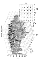
図5は、シンボルベースの周波数ランダム化されたサブキャリアの3次元スペクトログラムを示し、振幅対周波数対時間表現501とのログスケールによる比較を示すグラフである。比較のため、従来のシングル周波数キャリア信号502が重乗され、帯域のより低い周波数エンドに向かうシングルキャリアとして示される。このシングルキャリア信号は、通信妨害源又は干渉源と同様に作用する。周波数キャリアスペーシングを増加させることによるキャリア間干渉(ICI)の低下が示される。周波数毎にシンボルスペーシングを増加させることによるシンボル間干渉(ISI)の低下が示される。これは、連続するOFDMシンボルサブキャリアが同一周波数を使用せず、マルチパス遅延拡散からの悪影響が回避されることを確保する。シングルキャリアと同じ瞬間のSNRがまた示される。
FIG. 5 is a graph showing a three-dimensional spectrogram of symbol-based frequency randomized subcarriers and a log scale comparison with amplitude vs. frequency vs. time representation 501. For comparison, a conventional single
図6及び7を参照するに、それぞれ本発明の非限定的な実施例により利用可能な送信機100(図6)と受信機200(図7)の機能ブロック図が示される。図示されるような送信機100は、OFDMサブキャリアに周波数ホッピングアルゴリズムと、IFFT回路前にWalsh変換などの周波数ドメイン拡散手段を適用する。
Referring to FIGS. 6 and 7, functional block diagrams of a transmitter 100 (FIG. 6) and a receiver 200 (FIG. 7) that can be used according to non-limiting embodiments of the present invention, respectively, are shown. The
図示される送信機100と受信機200のハイレベルな構成要素の多くは、図1A及び1Bの従来のモデムに示される構成要素と機能的に同様のものであるが、図6及び7に示される送信機と受信機のブロック図に、さらなる詳細及び機能ブロック構成要素が追加される。参照のため、送信機の説明は100番台の参照番号から始められ、受信機の説明は200番台の参照番号から始められる。
Many of the high-level components of the
本発明の非限定的な一実施例によるWalsh変換可能な周波数ホッピングOFDM信号を生成するのに利用される追加的な機能的な構成要素は、擬似ランダム振幅位相生成手段102と、擬似ランダムサブキャリア配置回路104とを有する。生成手段102と回路104は共に、暗号化アルゴリズム106、暗号キー生成回路(Crypto−Key)108及びマスタクロック110と共に動作する。これらの構成要素は、一般に暗号化された擬似ランダム信号生成手段と呼ぶことができる。周波数ドメイン拡散回路112は、図示されるように、IFFT回路の前に配置され、Walsh変換を適用するなどによって、信号を周波数拡散するよう動作可能である。また、デジタル/アナログ変換手段は、スペクトル線を取り除くため、帯域幅調整DACサンプルレート回路114から信号を受信することができる。これらの構成要素が、以下で詳細に説明される。
Additional functional components utilized to generate a Walsh-convertable frequency hopping OFDM signal according to one non-limiting embodiment of the present invention include pseudo-random amplitude phase generation means 102 and pseudo-random subcarriers. And an
図6に示されるように、信号はデータバッファ120内で受信され、CRC生成手段121とデータスクランブル手段122とにわたされる。124で破線により示されるFECエンコーダ回路は、畳み込みエンコーダなどの順方向誤り訂正エンコーダ126と、パンクチャ回路128とを有することが可能である。符号化信号は、インタリーブ回路130内でインタリーブされる。信号は、132において破線により全体表示される変調・シンボルマッピング回路にわたされる。この変調・新ブルマッピング回路132は、QAM/PSK変調手段134と、パイロットキャリアとPAPRリダクションキャリアとを信号に挿入するパイロットキャリ・PAPRリダクションキャリア挿入回路136とを有する。本実施例では、PAPRは、ピーク・ツー・アベレージパワーレシオ(Peak−to−Average Power Ratio)に対応する。各キャリアは、サブキャリアマッピング回路138のマトリックス処理においてIFFTにマッピングされる。
As shown in FIG. 6, the signal is received in the
暗号化アルゴリズム106は、暗号キー回路108及びマスタクロック110だけでなく、本発明の非限定的な実施例によりQAM/PSK変調手段134に対する擬似ランダム信号を生成する擬似ランダム振幅・位相生成手段と共に動作する。擬似ランダムサブキャリア配置回路104はまた、サブキャリアマッピング回路138と共に動作し、暗号化アルゴリズム106から信号を受信する。OFDMサブキャリアは、このような手段により迅速に周波数ホッピングされる。
The
本発明の非限定的な実施例によると、周波数ドメイン拡散回路112が、IFFT回路140の前に配置され、周波数ドメインにおいてWalsh変換を適用する。周波数ドメイン拡散回路112がIFFT回路140の後に配置された場合、Walsh又は他の機能は時間ドメインの拡散を強いられる。周波数ドメイン拡散回路112とIFFT回路140は、典型的には、変調・マッピング回路132によりOFDM変調回路又はOFDM変調・マッピング回路としてみなすことができる。本発明の非限定的な実施例では、Walsh変換の適用からなされる拡散は、周波数ドメインにおいて行われる。ガードインターバルとしてのサイクリック拡張が、サイクリック拡張回路142内で付加可能である。FIR(Finite Impulse Response)フィルタ、コサインフィルタ又はレイズドコサインフィルタなどのシンボル整形フィルタ144は、サイクリック拡張に関するシンボル整形のための“時間ウィンドウ”として動作可能である。パケットバッファ146が信号を受信して、バッファリング後、信号はデジタル/アナログ変換手段148においてアナログ信号に変換される。D/A変換手段148はまた、スペクトル線を取り除くさらなる処理のため、帯域幅調整DACサンプルレート回路114から信号を受信する。D/A変換手段148は、無線集積回路(IC)ワイドバンド低速周波数ホッピング回路150に信号をわたす。RFキャリアは、帯域幅を増大させるため、擬似ランダム周波数ホッピングアルゴリズムにより処理可能であり、図示されるように、周波数アップ変換手段として動作する。
According to a non-limiting embodiment of the present invention, frequency
周波数アップ変換回路150の基本的な構成要素は、ミキサ154への信号を受信する送信チェーン回路152を有することが可能である。当該信号は、バンドパスフィルタ156、アンプ系列158及びSPDT(Single Pole Double Throw)スイッチ160にわたされる。スイッチ後、ローパスフィルタ162は信号をフィルタリングする。無線信号は、アンテナ166を介した以降の送信のため、パワーアンプ164により増幅される。回路150の他の構成要素は、PLL(Phase−Locked Loop)回路170と、非限定的な具体例としての40MHz信号生成手段172と、ローパスフィルタ174と、アンプ176と、シンセサイズ170と、他のアンプ180と、バンドパスフィルタ182と、加算回路184と、ミキサ154に接続される他のアンプ186とを含む。周波数アップ変換回路150の構成要素は、OFDMベースバンド波形全体が異なる中心周波数に周波数変換される低レート周波数ホッピング方式に作用するのに利用されてもよい。このような低速周波数ホッピングはさらに、干渉をガードすることがデキ、低速ホッピングシーケンスが構成される場合、更なるレベルの暗号化を提供することが可能である。
The basic components of the frequency up-
図示されるような送信機100は、非限定的な実施例であり、他の多数のタイプの送信機が利用可能である。DSP及び他の回路機能の進歩によって、処理はおそらくベースバンドにおいて直接行うことが可能であることが理解されるべきである。
The
また、サブキャリアマッピング回路138は各キャリアをIFFT回路140にマッピングすることが理解されるべきである。例えば、IFFT回路140が周波数ドメインにおいて64サンプル信号による入力を有する場合、それは、マトリック演算として時間ドメインにおいて64サンプル信号を与えるであろう。サブキャリアマッピング回路138は、任意のサブキャリアにシンボルを配置するため、ベクトルの順序を変更し、他のサブキャリアにゼロを適用することが可能である。例えば、64サンプルベクトルにおける一部のサンプルがゼロとなり、これは、それらがオフである場合、周波数ドメインに出現しないことを意味する。オン又は非ゼロの何れかが、周波数ホッピングOFDM信号を生成するため、各IFFTサイクルで(シンボル毎に1回)位置を変更する。OFDM信号の周波数ホッピングの性質は、暗号化アルゴリズム106、擬似ランダムサブキャリア配置回路104及び擬似ランダム振幅・位相生成手段102により生成される。QAM/PSK変調手段134は、コンステレーション振幅及び位相を生成するのに利用される。
It should also be understood that the
本発明の一特徴は、データが暗号化されていることを意図しない受信者に目立たなくすることに関する。暗号化を目立たなくするため、送信機により3つの未知のものが生成される。例えば、a)未知の送信される振幅と位相、b)未知の擬似ランダム振幅及び位相、並びにc)未知のチャネル振幅及び位相である。未知のものが3つあるため、暗号キーとマスタクロックに基づき暗号化アルゴリズムにより何れの信号が送信されるか知ることは不可能である。 One aspect of the present invention relates to making data unobtrusive to unintended recipients. In order to make the encryption less noticeable, three unknowns are generated by the transmitter. For example, a) unknown transmitted amplitude and phase, b) unknown pseudorandom amplitude and phase, and c) unknown channel amplitude and phase. Since there are three unknowns, it is impossible to know which signal is transmitted by the encryption algorithm based on the encryption key and the master clock.
周波数ドメイン拡散回路112は、マトリック演算として動作する。例えば、64IFFT回路140が利用される場合、サブキャリアを周波数拡散し、処理ゲインを提供するため、64×64Walshマトリックス(非限定的な実施例として)が利用可能である。入力ベクトルがWalshマトリックスと乗算される。Walshマトリックスは“2”の冪乗とすることができる次元を有した正方行列であることが理解されるべきである。そのエントリは、+1又は−1である。Walshマトリックスは、符号変更数が昇順、すなわち、シーケンシャルな順序となるように各行を配置することによって、同じ次元の再帰的な式により定義されるアダマール行列から取得可能である。Walsh行列の各行は、Walsh関数に対応する。Walshマトリックスの各行の順序は、ビットリバースパーミュテーション(bit−reversal permutation)とGray符号パーミュテーションとを適用することによって、アダマール行列の順序付けから求めることが可能である。Walsh関数は、単位インターバル上で積分可能な平方の直交基底を構成する。従って、それは、“擬似ランダムノイズ符号”としても知られている暗号化に利用するのに適した統計的に一意的な数の集合を構成する。この乗算は、加算と減算の系列として効率的に実現可能である。
The frequency
帯域幅調整DACサンプルレート回路114は、D/A変換手段148と共に動作し、サンプルレートを調整し、スペクトル線を取り除くことができる。この結果、スペクトログラムにより波形を検出することは困難となる。図示されるような送信機100は、Walsh変換による周波数ホッピングOFDM信号を構成するよう動作することが理解されるべきである。例えば、シンボル毎に64のサンプルによるIFFTが使用される場合、各サブキャリアの周波数位置は、64サンプル毎に変化しうる。例えば、IFFTが4ミリ秒毎に計算される場合、64すべてのキャリア上の周波数ホッピングは、高速なホッピングレートを与えるため、4ミリ秒毎に実行可能である。これはシンボル単位で実行可能であるため、サブキャリア周波数位置がランダムに変更されることから、上述されるような周波数ホッピングOFDM通信システムはまた、シンボルベースランダム化OFDMと呼ぶことができる。他の受信機は、暗号化アルゴリズムと関連する回路及び完全な同期なしにサブキャリア位置を決定することはできないであろう。
The bandwidth adjustment DAC
図7は、本発明の非限定的な実施例により利用可能な受信機200のハイレベル機能ブロック図を示す。暗号化アルゴリズム回路、暗号キー回路、マスタクロック、擬似ランダム振幅・位相生成手段、擬似ランダムサブキャリア配置回路、帯域幅調整ADCサンプルレート回路など、図6のブロック図に使用される同様の構成要素は、それらがここでは200番台で配置されることを除いて、図6に使用されるものと同様の参照番号が与えられる。この受信回路200はまた、シンボルベースサブキャリア同期回路216の追加を含む。それはまた、図6の送信機100と同様に、周波数ドメイン拡散回路112の代わりに、周波数ドメイン逆拡散回路212を利用する。
FIG. 7 shows a high level functional block diagram of a
この受信回路200について示される他のハイレベル構成要素は、アンテナ220と、低ノイズアンプ(LNA)222と、図6の送信機100に示される無線ICワイドバンド低速周波数ホッピング回路150によってワイドバンドについて処理された場合、周波数ホッピングキャリア信号を逆処理可能な無線ICダウン変換手段224とを含む。アナログ/デジタル変換手段226は、ダウン変換手段224からIF又はベースバンド信号を受信し、帯域幅調整ADCサンプルレート回路214から信号を受信し、送信機100で用いられる処理の逆処理をする。信号は、さらなる処理のためサブキャリアを同期させるシンボルベースサブキャリア同期回路216と、データバッファ228に転送される。ガードインターバル回路230はガードインターバルを取り除き、信号はFFT回路232におけるOFDM復調手段としての高速フーリエ変換により処理される。逆Walsh変換が、逆Walsh変換回路212において適用される。サブキャリアマッピング・復調回路が、234において破線により示され、サブキャリアデマッピング回路236において各サブキャリアに逆マッピング処理を実行し、パイロット除去回路238においてパイロットトーンを削除し、シンボル・ツー・ナンバー(QAM/PSK)復調回路240において信号を復調する。デインタリーブ回路242は、信号をデインタリーブする。復号化回路が、244において破線により示され、デパンクチャ回路246内のデパンクチャ処理と、Viterbiデコーダ248などのFECデコーダ内のViterbi復号化などの順方向誤り訂正(FEC)復号化のため動作する。データデスクランブル手段250において、データデスクランブルが実行され、データバッファ252にデータバッファリングされ、CRC回路254によりCRCチェックが行われる。
Other high-level components shown for this
図6及び7に示される送信機100と受信機200は、高速キャリア周波数ホッピング信号である信号を生成及び受信することができる。このホッピングは、1MHzの帯域幅を有するシングルキャリアを利用して、80MHzの無線周波数帯域幅上で毎秒1600ホップにより周波数をホッピングする従来のブルートゥースシステムよりはるかに高速化できる。また、例えば、図4に示されるように、信号対ノイズ比(S/N)の変化は、サブキャリアの個数に基づき、適応的無線通信システムにおける瞬間的なサブキャリアS/N対データレートの範囲を変更する方法として利用可能であることが理解されるべきである。
The
例えば、受信機200は、チャネル推定シンボル、プリアンブル又は特別なチャネル推定パケットなどを利用することによって、サブキャリア毎の受信S/Nを測定することができる。情報は、送信機100がネゴシエートされたチャネルマスクを用いて所望されない周波数による送信を回避できるように、“オフ”にすべきサブキャリアの個数とチャネルの障害となる干渉源の可能性のある周波数位置とを示す“チャンルマスク”として、送信機に戻すことができる。一実施例では、10個のキャリが100MHzの帯域幅上で同時にオンされ、各キャリアは、毎秒1,562,500回ホッピングできるように、640ナノ秒(1/FFTレートに対応する)間送信される。これは、ブルートゥースプロトコルより約1000倍高速なホッピングであり、数十倍以上のデータレートを提供することができる。
For example, the
送信機100は、特定の周波数にある複数のサブキャリアを生成し、上述されるような周波数ホッピングアルゴリズムを適用することによって、各サブキャリア周波数について擬似ランダム周波数ホップを生成することができる。IFFT回路140は、特定の周波数にある複数のサブキャリアを生成する。本発明の非限定的な実施例によると、必要に応じてすべてのサブキャリアが利用可能であるが、可能なすべてのサブキャリアのうちの僅かなサブセットしか何れか1つの時点では利用される必要はない。例えば、上述された実施例と同様に、64のサブキャリアの代わりに、本実施例では10個のサブキャリアしか利用可能でなく、毎秒1,562,500のホッピングが与えられる。
The
サブキャリア中心周波数は、擬似ランダム周波数について暗号化アルゴリズムを利用してOFDMシンボルレートにより変更可能である。これは、各キャリアがIFFTにマッピングされる変調・マッピング回路132において行われる。各サブキャリアの中心周波数は、周波数ホッピングアルゴリズムによりランダムに見えうる。シンボル期間は、上述されるように、極めて短くすることができ、このため、各サブキャリアは、何れか特定の周波数において短時間出現することとなる。
The subcarrier center frequency can be changed by the OFDM symbol rate using an encryption algorithm for the pseudo-random frequency. This is performed in the modulation and
ガード時間は、連続するシンボルが同じ周波数位置におけるサブキャリアを含まないことを確実にすることによって、短縮又は排除することができる。例えば、従来のシステムでは、2つのシンボルが同一周波数上で連続する場合、同一位置において異なる時点にマルチパス信号が到来する可能性がある。図6及び7に示されるシステム及び回路を使用することによって、これらの信号は同一周波数上には現れず、典型的にはマルチパスによる影響を受けない。従って、シンボル間干渉(ISI)が回避され、必要とされるガード時間を実質的に減少させ、送信オーバヘッドを低減し、データレートを向上させることができる。 The guard time can be shortened or eliminated by ensuring that consecutive symbols do not contain subcarriers at the same frequency location. For example, in a conventional system, when two symbols are consecutive on the same frequency, a multipath signal may arrive at a different time at the same position. By using the systems and circuits shown in FIGS. 6 and 7, these signals do not appear on the same frequency and are typically not affected by multipath. Thus, intersymbol interference (ISI) can be avoided, the required guard time can be substantially reduced, transmission overhead can be reduced, and data rate can be improved.
図6及び7に示されるような送信機100と受信機200とを利用して、“ガードインターバル”などのガード時間を排除又は実質的に減少させることが可能である。また、連続するシンボルについて、各行に周波数が2回使用できないように、周波数ホッピングアルゴリズムを変更することによって、追加的なガードが付加可能であり、これにより、マルチパスチャネル効果によりシンボル間干渉(ISI)を回避することができることが理解されるべきである。上述されるように、これは、要求されるガードインターバルを排除又は実質的に減少させ、送信オーバヘッドを軽減し、データレートを向上させる。
Using a
要求されるデータレートに応じてサブキャリアを動的に追加及び削除することが可能である。キャリア間干渉(ICI)を減少させるため、最小キャリアスペーシングが増大可能であり、周波数ホッピング信号により、ジャミングに対するロウバスト性、すなわち、アンチ・ジャミング(AJ)機能を提供する。各キャリアが周波数ドメインにおいて互いに隣り合って送信されない限り、キャリア間干渉は低減される。 It is possible to add and delete subcarriers dynamically according to the required data rate. To reduce inter-carrier interference (ICI), the minimum carrier spacing can be increased, and the frequency hopping signal provides robustness against jamming, ie, anti-jamming (AJ) functionality. As long as each carrier is not transmitted next to each other in the frequency domain, inter-carrier interference is reduced.
また、キャリア周波数は擬似ランダムにホッピングし、広い帯域幅をカバーすることができる。これは、図6に示される無線ICワイドバンド低速周波数ホッピング回路150により実現可能であり、周波数アップ変換回路として動作可能である。
The carrier frequency can be hopped pseudo-randomly to cover a wide bandwidth. This can be realized by the wireless IC wideband low-speed
“デッドタイム(dead−time)”擬似乱数生成手段が、“オン”時間を減少させるためシステムに導入可能であり、シンボル間の出力スペーシングを増大させることができる。このスペーシングは、スペクトル線を回避し、信号の周期定常的な統計量を減少させるため、擬似乱数生成手段を利用して可変とすることができる。このタイプのシステムは、出力サンプル制御なしに実現可能である。システムは、送信前にランダムな期間待機可能である。スペクトル線を取り除くことによって、他のシステムが送信された通信を検出することはより困難になる。周期定常的(cyclostationary)とは、信号の2次統計量としての標準偏差を意味しうる。出力サンプル制御は、D/A変換手段148における制御を意味しうる。
A “dead-time” pseudo-random number generator can be introduced into the system to reduce the “on” time, and can increase the output spacing between symbols. This spacing can be made variable using pseudo-random number generation means to avoid spectral lines and reduce the periodic statistic of the signal. This type of system can be implemented without output sample control. The system can wait for a random period before sending. By removing the spectral lines, it becomes more difficult for other systems to detect transmitted communications. Cyclostationary can mean the standard deviation as a second order statistic of the signal. Output sample control can mean control in the D /
サブキャリアコンステレーションの振幅と位相の各値はまた、図6に示されるような変調手段134と共に動作する生成手段102を用いて擬似ランダムに変更可能である。例えば、擬似ランダムな振幅と位相の各値は、暗号化アルゴリズムを用いて生成可能である。擬似ランダムな振幅と位相の各値は、送信前に意図した振幅と位相の各値に加算可能である。擬似ランダムな振幅と位相の各値を各サブキャリアに加えることによって、シンボルコンステレーションはもはや標準的なQAM/PSKではない。送信信号が意図しない受信機に検出された場合、当該受信機は、未知なものが多すぎて、信号を復調することはできないであろう。例えば、送信又は意図された振幅と位相は、信号に加えられた擬似ランダムな振幅と位相と共に未知であり、マルチパスのチャネル振幅と位相もさらに未知である。これは、3つの未知なものをもたらす。擬似ランダムな振幅と位相の各値は、認証されていない又は意図されていない受信機に対して典型的なランダムチャネル効果として現れることになるであろう。 The amplitude and phase values of the subcarrier constellation can also be changed pseudo-randomly using the generating means 102 operating with the modulating means 134 as shown in FIG. For example, pseudo-random amplitude and phase values can be generated using an encryption algorithm. The pseudo-random amplitude and phase values can be added to the intended amplitude and phase values before transmission. By adding pseudo-random amplitude and phase values to each subcarrier, the symbol constellation is no longer standard QAM / PSK. If a transmitted signal is detected by an unintended receiver, the receiver will not be able to demodulate the signal because there are too many unknowns. For example, the transmitted or intended amplitude and phase are unknown along with the pseudo-random amplitude and phase added to the signal, and the multipath channel amplitude and phase are also unknown. This results in three unknowns. Pseudorandom amplitude and phase values will appear as typical random channel effects for unauthenticated or unintended receivers.
これらのアルゴリズムは、ソフトウェア無線(SDR)に追加可能であり、データレートと変調を変更するための改良により実現可能であることが理解されるべきである。データレート、帯域幅、送信パワー及びLPI/LPDパフォーマンスは、サブキャリア変調方式、サンプルレート、IFFTサイズ、IFFT期間及びOFDMシンボル毎に使用されるサブキャリア数を変更することによって向上させることが可能である。 It should be understood that these algorithms can be added to software defined radio (SDR) and can be implemented with improvements to change the data rate and modulation. Data rate, bandwidth, transmission power and LPI / LPD performance can be improved by changing the subcarrier modulation scheme, sample rate, IFFT size, IFFT period and the number of subcarriers used per OFDM symbol. is there.
図6に示されるように、Walsh変換は、周波数ドメイン拡散回路112を用いてIFFT回路140の前に適用されるため、周波数拡散のために周波数ドメインにおいて適用可能である。Walsh変換は、典型的には、時間ドメイン拡散のためと、マルチアクセス方式のための直交符号の生成のため、CDMAなどの通信システムにおいて利用されることが知られている。Walsh変換は、周波数ドメインにおいてサブキャリアを拡散するため、本発明のシステム、装置及び方法において利用可能である。これは、LPI/LPDのパフォーマンスを向上させるため、平均パワー(dBm/Hz/sec)の大きな減少を提供することが可能であり、同一のFCCスペクトルマスク内でより多くの送信パワーを可能にし、周波数ドメイン処理ゲインを提供することにより、周波数選択性フェージングの効果を低減する。それはまた、さらなるアンチ・ジャミング(AJ)のロウバスト性を提供する。また、アウト・オブ・バンドノイズ(OBN)放出が、Walsh変換により引き起こされるより急峻な“ロール・オフ”のため、時間ウィンドニング(time−windowing)と同様に減少可能である。マトリックスとしてのWalsh変換は、+1と−1のみから構成され、加算と減算のみを必要とし、乗算を必要としない。これは、同一のFCCスペクトルマスクについて、キャリア数対データレート対送信パワー及び距離のトレード・オフを可能にする。Walsh変換では、マトリックスの各行は、互いに交換可能である。変換は依然として受信機200において直交する。これらの行の置換は、さらなるLPIの向上のため実行可能である。
As shown in FIG. 6, the Walsh transform is applied in front of the
OFDMは、マルチパスによる周波数選択性フェージングの影響を受けることが理解されるべきである。Walsh変換は、周波数選択性フェージングに対するロウバスト性とシステムへの処理ゲインを提供可能である。 It should be understood that OFDM is subject to frequency selective fading due to multipath. The Walsh transform can provide robustness to frequency selective fading and processing gain to the system.
上述されるようなシステム、装置及び方法は、OFDMシンボルレートなどにおいてサブキャリア周波数位置を変更することによって、極めて高速な周波数ホッピングを提供する。従って、それは、低LPI及び低LPDを提供するため、経時的に減少するスペクトル密度(dB/Hz/sec)を提供することが可能である。上述されるシステムは、ブルートゥースシステムよりはるかに高速であり、FCCスペクトルマスク内の送信をより大きな距離により可能にする。それはまた、各サブキャリアが連続するOFDMシンボルについて同一の周波数上に現れないことを確実にすることによって、ガードインターバルを排除又は実質的に減少させる。システムはまた、マルチパスによるシンボル間干渉(ISI)に対するロウバスト性を提供する。Walsh変換は、スペクトル上に周波数ホッピングサブキャリアを拡散し、LPI/LDPのパフォーマンスを向上させるため、又はFCCスペクトルマスク要求に従うことに供するため、パワースペクトル密度(dB/Hz)を低下させるよう周波数ドメインに適用可能である。それはまた、周波数選択性フェージングに対する処理ゲインを提供すると共に、ジャミングに対するロウバスト性を提供することが可能である。 The systems, apparatus and methods as described above provide very fast frequency hopping by changing the subcarrier frequency position, such as in the OFDM symbol rate. Thus, it can provide a spectral density (dB / Hz / sec) that decreases over time to provide low LPI and low LPD. The system described above is much faster than the Bluetooth system and allows transmission within the FCC spectral mask at greater distances. It also eliminates or substantially reduces the guard interval by ensuring that each subcarrier does not appear on the same frequency for consecutive OFDM symbols. The system also provides robustness against inter-symbol interference (ISI) due to multipath. The Walsh transform spreads frequency hopping subcarriers over the spectrum and serves to improve the performance of LPI / LDP, or to comply with FCC spectrum mask requirements, to reduce the power spectral density (dB / Hz). It is applicable to. It can also provide processing gain for frequency selective fading and provide robustness against jamming.
図8A及び8Bを参照するに、従来のシングルキャリア波形とシンボルベースランダム化周波数ホッピングサブキャリアとの間のスペクトル比較が示される。上側のグラフに示されるように、周波数は水平軸上にあり、デシベル単位の相対パワーは垂直軸上にある。ベースバンドにおいてスペクトルが示され、平均強度が、従来システムに対する30デシベルのLPDの向上と共に示される。より多くのパワーが、同一のFCCスペクトルマスク内で送信可能である。本発明の非限定的な実施例により、デジタルデータを送信する無線局又は他の送信機が、それのOFDM信号を周波数ホッピングし、平均パワーを低下させることが可能である。 Referring to FIGS. 8A and 8B, a spectral comparison between a conventional single carrier waveform and symbol-based randomized frequency hopping subcarriers is shown. As shown in the upper graph, the frequency is on the horizontal axis and the relative power in decibels is on the vertical axis. The spectrum is shown in baseband and the average intensity is shown with a 30 dB LPD improvement over the conventional system. More power can be transmitted within the same FCC spectrum mask. A non-limiting embodiment of the present invention allows a wireless station or other transmitter that transmits digital data to frequency hop its OFDM signal and reduce the average power.
図9は、送信機の近接位置などにおけるノイズのスペクトル比較を示す。 FIG. 9 shows a spectral comparison of noise, such as in the proximity of the transmitter.
図10は、本発明の非限定的な実施例によるWalsh変換前の送信された周波数ホッピングOFDM信号を3次元で示すグラフである。周波数ホッピングOFDM信号が示される。 FIG. 10 is a graph showing in three dimensions a transmitted frequency hopping OFDM signal before Walsh transform according to a non-limiting example of the present invention. A frequency hopping OFDM signal is shown.
図11は、本発明の非限定的な実施例による、パワーがさらに減少されるWalsh変換後の送信された周波数ホッピングOFDM信号を示す3次元グラフである。各サブキャリアは、Walsh変換が周波数ドメインに適用される。サブキャリアは、ヘルツ毎のパワーを、Walsh変換前より大きく減少させるため、周波数上に拡散される。 FIG. 11 is a three-dimensional graph illustrating a transmitted frequency hopping OFDM signal after a Walsh transform with further reduced power, according to a non-limiting example of the present invention. For each subcarrier, the Walsh transform is applied in the frequency domain. The subcarriers are spread over the frequency in order to reduce the power per Hertz more than before the Walsh transform.
図12は、本発明の非限定的な実施例による、Walsh変換のシンボルベースランダム化サブキャリアへの付加を示すグラフである。それがオフ及びオンになるときのWalsh変換が示され、さらに様々なパワーの相違が示される。 FIG. 12 is a graph illustrating the addition of a Walsh transform to a symbol-based randomized subcarrier according to a non-limiting example of the present invention. The Walsh transform is shown as it turns off and on, and various power differences are shown.
図13は、逆Walsh変換前の受信周波数ホッピングOFDM信号を3次元に示し、暗号化アルゴリズムを知ることなく信号を復号化することがどれだけ困難であるか示すグラフである。 FIG. 13 is a graph showing the reception frequency hopping OFDM signal before the inverse Walsh conversion in three dimensions, and how difficult it is to decrypt the signal without knowing the encryption algorithm.
図14Aは、信号が“ポップ”アウトし、復号化可能な逆Walsh変換の適用後の図13からの受信信号を示す3次元グラフである。逆Walsh変換後の受信信号コンステレーションが、図14Bの右下に示される。 FIG. 14A is a three-dimensional graph showing the received signal from FIG. 13 after applying the inverse Walsh transform, where the signal “pops out” and can be decoded. The received signal constellation after inverse Walsh conversion is shown in the lower right of FIG. 14B.
図15A及び15Bは、シングルキャリアシステムが1501のバンドの中央に示されるWalsh変換前後の周波数ホッピングOFDM信号を示す。図15Bのグラフに示されるように、Walsh変換後、シングルキャリアはWalsh変換を適用されず、本発明の非限定的な実施例による周波数ホッピングを受ける他のOFDM信号が周波数上に拡散される。 FIGS. 15A and 15B show frequency hopping OFDM signals before and after the Walsh transform where the single carrier system is shown in the middle of the 1501 band. As shown in the graph of FIG. 15B, after the Walsh transform, the single carrier is not applied with the Walsh transform, and other OFDM signals subjected to frequency hopping according to a non-limiting embodiment of the present invention are spread over the frequency.
図16は、干渉源が逆Walsh変換後に周波数上に拡散される官署威厳による周波数ドメイン逆拡散を示す3次元グラフである。従って、干渉源による周波数ドメイン逆拡散がある。 FIG. 16 is a three-dimensional graph showing frequency domain despreading due to public authority where the interference source is spread over the frequency after the inverse Walsh transform. Thus, there is frequency domain despreading due to interference sources.
図17は、ノイズ追加前の同様のシミュレーションにおけるWalsh変換前の送信OFDM信号を示す。この図は、周波数ドメイン拡散の適用とノイズのあるチャネルによる送信前の送信信号を示す。 FIG. 17 shows a transmission OFDM signal before Walsh conversion in a similar simulation before adding noise. The figure shows the application of frequency domain spreading and the transmitted signal before transmission over a noisy channel.
図18は、実際のノイズ環境のための逆Walsh変換前の干渉源による受信OFDM信号と拡張された干渉源信号とを示す。ノイズフロア上に、周波数ホッピング及び拡散OFDM信号が示される。 FIG. 18 shows the received OFDM signal and the extended interferer signal by the interferer before the inverse Walsh transform for the actual noise environment. On the noise floor, frequency hopping and spread OFDM signals are shown.
図19は、干渉源によるWalsh変換オン及びオフのスペクトル比較を示し、干渉源、周波数ホッピングOFDM信号及びWalsh変換信号の位置を示すグラフである。 FIG. 19 is a graph showing a spectrum comparison of Walsh transform on and off by an interference source, and showing positions of the interference source, the frequency hopping OFDM signal, and the Walsh transform signal.
図20は、逆Walsh変換前の干渉源による受信周波数ホッピング及び拡散OFDM信号のパワースペクトルである。 FIG. 20 is a power spectrum of a reception frequency hopping and spread OFDM signal by an interference source before inverse Walsh conversion.
図21は、干渉源が逆Walsh変換後に周波数上に拡散される干渉源による周波数ドメイン逆拡散を示す2次元のグラフである。 FIG. 21 is a two-dimensional graph showing frequency domain despreading by an interference source in which the interference source is spread over frequency after inverse Walsh transform.
図22は、逆Walsh変換後に周波数上に拡散された干渉源による周波数ドメイン逆拡散と、受信信号コンステレーションを示すグラフである。 FIG. 22 is a graph showing the frequency domain despreading by the interference source spread on the frequency after the inverse Walsh transform and the received signal constellation.
本発明により使用するため改良可能な通信システムの一例が、図23を参照して与えられる。 An example of a communication system that can be improved for use with the present invention is given with reference to FIG.
このようなシステム及び方法により利用可能な無線の一例は、フロリダ州のメルボルンのハリスコーポレイションにより製造販売されているFalconTMIIIラジオである。FalconTMIIIは、基本的送信スイッチと、当業者に知られている他の機能スイッチ及びコントロールとを有することが可能である。限定されることなく、典型的には、相対的に標準的なプロセッサとハードウェアコンポーネントにより実現可能なソフトウェアにより規定されるラジオを含む各種ラジオが利用可能であることが理解されるべきである。あるソフトウェアラジオのクラスは、所望の通信波形を実現するのに適した波形ソフトウェアモジュールと共に、相対的に標準的なラジオ及び処理ハードウェアを含むJTR(Joint Tactical Radio)である。JTRラジオはまた、参照することによりその内容のすべてがここに援用される、ソフトウェア通信アーキテクチャ(SCA)仕様書(www.jtrs.saalt.milを参照されたい)に準拠するオペレーティングシステムソフトウェアを利用する。SCAは、各メーカー及び開発者が各自のコンポーネントを1つの装置に容易に統合できるように、ハードウェア及びソフトウェアコンポーネントがどのように相互作用するかを規定するオープンアーキテクチャフレームワークである。 One example of a radio that can be used with such a system and method is the Falcon ™ III radio manufactured and sold by Harris Corporation of Melbourne, Florida. The Falcon ™ III can have a basic transmit switch and other functional switches and controls known to those skilled in the art. It should be understood that, without limitation, various radios are typically available, including software defined radios that can be implemented with relatively standard processors and hardware components. One class of software radio is JTR (Joint Tactical Radio), which includes relatively standard radio and processing hardware, along with waveform software modules suitable for implementing the desired communication waveforms. JTR Radio also utilizes operating system software that conforms to the Software Communication Architecture (SCA) specification (see www.jtrs.saalt.mil), the contents of which are hereby incorporated by reference in their entirety. . SCA is an open architecture framework that defines how hardware and software components interact so that manufacturers and developers can easily integrate their components into a single device.
JTRS(Joint Tactical Radio System)SCAは、ソフトウェア無線(SDR)を実現するため、しばしばCORBA(Common Object Request Broker Architecture)に基づくインタフェース及びプロトコル群を規定する。部分的には、JTRSとそれのSCAは、ソフトウェアリプログラマブルラジオのファミリーと共に利用される。また、SCAは、ソフトウェアリプログラマブルデジタルラジオを実現するための特定のルールセット、方法及び設計基準である。 In order to realize software radio (SDR), JTRS (Joint Tactical Radio System) SCA often defines an interface and a group of protocols based on CORBA (Common Object Request Broker Architecture). In part, JTRS and its SCA are used with a family of software reprogrammable radios. SCA is a specific rule set, method and design standard for realizing software reprogrammable digital radio.
JTRS SCA仕様書は、JTRSジョイントプログラムオフィス(JPO)により公表されている。JTRS SCAは、開発コストを低減し、設計モジュールを再利用する機能を介し新たな波形の開発時間を短縮し、商業的なフレームワークとアーキテクチャとの進化に基づくように、異なるJTRS SCA実現形態の間のアプリケーション規格のポータビリティと、リバレッジコマーシャル規格を提供するよう構成された。 The JTRS SCA specification is published by the JTRS Joint Program Office (JPO). JTRS SCA reduces development costs, shortens the development time for new waveforms through the ability to reuse design modules, and is based on the evolution of commercial frameworks and architectures, as well as different JTRS SCA implementations. It was configured to provide portability of application standards and leveraged commercial standards.
JTRS SCAは、実現形態に独立となるよう意図されているため、システム仕様ではなく、所望のJTRSの目的を実現するためのシステムの設計を制限するルールセットである。JTRS SCAのソフトウェアフレームワークは、動作環境(OE)を規定し、当該環境からアプリケーションが使用するサービスとインタフェースとを規定する。SCA OEは、コアフレームワーク(CF)と、CORBAミドルウェアと、関連するボードサポートパッケージを有するポータブルオペレーティングシステムインタフェース(POSIX)に基づくオペレーティングシステム(OS)とを有する。JTRS SCAはまた、アプリケーションソフトウェアコンポーネントの間のアプリケーションプログラミングインタフェース(API)を規定するための構築ブロック構成(APIサプルメントに規定される)を提供する。 Since the JTRS SCA is intended to be independent of the implementation, it is not a system specification but a rule set that limits the design of the system to achieve the desired JTRS objective. The software framework of the JTRS SCA defines an operating environment (OE) and defines services and interfaces used by applications from the environment. The SCA OE has an operating system (OS) based on a core framework (CF), CORBA middleware, and a portable operating system interface (POSIX) with an associated board support package. The JTRS SCA also provides a building block configuration (defined in the API supplement) for defining application programming interfaces (APIs) between application software components.
JTRS SCAコアフレームワーク(CF)は、埋め込み分散計算通信システムにおけるソフトウェアアプリケーションコンポーネントの配置、管理、相互接続及び相互通信を提供するオープンソフトウェアインタフェース及びプロファイルの重要な“コア”セットを規定するアーキテクチャコンセプトである。インタフェースは、JTRS SCA仕様書に規定されるかもしれない。しかしながら、開発者はそれらの一部を実現し、一部は非コアアプリケーション(すなわち、波形など)により実現され、一部はハードウェアデバイスプロバイダにより実現されるかもしれない。 The JTRS SCA Core Framework (CF) is an architectural concept that defines an important “core” set of open software interfaces and profiles that provide the placement, management, interconnection and intercommunication of software application components in embedded distributed computing communication systems. is there. The interface may be specified in the JTRS SCA specification. However, developers realize some of them, some are realized by non-core applications (ie, waveforms, etc.), and some may be realized by hardware device providers.
説明のため、図23に示される非限定的な実施例に関して、本発明を利用する通信システムの具体例の簡単な説明が与えられる。通信システム350のハイレベルブロック図は、本発明に使用するため改良可能な基地局セグメント352と無線メッセージ端末とを有する。基地局セグメント352は、いくつかの各自のVHFラジオ368及びHFラジオ370と、ラジオ又は無線装置368,370に接続されたパーソナルコンピュータワークステーション372とを含むVHFネット364又はHFネット366との無線リンクを介し音声又はデータを通信及び送信するVHFラジオ360とHFラジオ362とを含む。アドホック通信ネットワーク373は、図示されるような各種コンポーネントと相互に動作する。このため、HF又はVHFネットワークは、アドホック通信ネットワークとしてインフラストラクチャに依存せず動作するHF及びVHFネットセグメントを含むことが理解されるべきである。UHFラジオ及びネットセグメントは図示されていないが、これらを含めることができる。
For purposes of explanation, a brief description of a specific example of a communication system utilizing the present invention will be given with respect to the non-limiting example shown in FIG. The high-level block diagram of the
HFラジオは、復調回路362aと、適切な畳み込みエンコーダ回路362bと、ブロックインタリーブ手段362cと、データランダム化回路362dと、データ・フレーム化回路362eと、変調回路362fと、適合したフィルタ回路362gと、適切なクランピングデバイスを有するブロック又はシンボルイコライザ回路362hと、デインタリーブ・デコーダ回路362iと、モデム362jと、パワー適応化回路362hとを非限定的な例として含むことが可能である。ボコーダ(vocoder)(ボイスエンコーダ/デコーダ)回路362lは、上述されるような各種回路の組み合わせ又は独立した回路とすることができる符号化・復号化機能と変換ユニットとを有することが可能である。送信キースイッチ362mは、上述されるように動作する。上記及び他の回路が、本発明に必要な何れかの機能と共に、当業者により示唆される他の機能とを実行するよう動作する。ここに参照される回路は、以下に限定するものでないが、汎用マイクロプロセッサと関連するソフトウェア、デジタル信号処理に特化したマイクロプロセッサと関連するソフトウェア、特定用途向け集積回路(ASIC)、FPGA(Field Programmable Gate Array)、論理回路、又は当業者に知られている他のタイプのデバイス、ソフトウェア又はファームウェアを含むソフトウェア及び/又はハードウェア要素の何れかの組み合わせを含むかもしれない。すべてのVHF移動局及び送受信局を含む他の示されたラジオは、同様の機能回路を有しうる。
The HF radio includes a demodulation circuit 362a, a suitable convolutional encoder circuit 362b, a block interleaving means 362c, a
基地局セグメント352は、PABX382に接続されるPSTN(Public Switched Telephone Network)380との地上接続を含む。衛星地上局などの衛星インタフェース384は、PABX382に接続され、PABX382は、無線ゲートウェイ386a,386bを構成するプロセッサに接続される。これらは、VHFラジオ360又はHFラジオ362に相互接続される。プロセッサは、ローカルエリアネットワークを介しPABX382と電子メールクライアント390に接続される。ラジオは、適切な信号生成手段と変調手段とを有する。本発明の技術を利用してネットワーク内で送信されるパケット化又は非パケット化デジタル音声情報は、RF−6010タクティカルネットワークハブなどの無線ゲートウェイ装置に付属されるラジオ、電話若しくは他のインタフェース装置、又はPSTN内若しくはPABXに接続される加入電話の1つに接続される受話器から発信又は受信可能である。
イーサネット(登録商標)/TCP−IPローカルエリアネットワークは、“無線”メールサーバとして機能しうる。電子メールメッセージは、第2世代プロトコル/波形としてSTANAG−5066を用いて無線リンク及びローカル無線ネットワークを介し送信可能であり、もちろん、好ましくは、第3世代相互運用規格であるSTANAG−4538と動作可能であり、それらの開示は参照することによりここに援用される。参照することによりここに援用される相互運用規格FED−STD−1052が、レガシー無線装置と共に利用可能である。本発明に利用可能な装置の例として、フロリダ州メルボルンのハリスコーポレイションにより製造された異なる無線ゲートウェイ及び無線装置があげられる。この装置は、非限定的な実施例として、RF5800,5022,7210,5710,6010,5285及びPRC117,138シリーズの装置を含む。 An Ethernet / TCP-IP local area network can function as a “wireless” mail server. E-mail messages can be sent over wireless links and local wireless networks using STANAG-5066 as second generation protocol / waveform, and of course preferably operate with STANAG-4538, a third generation interoperability standard The disclosures of which are incorporated herein by reference. The interoperability standard FED-STD-1052, incorporated herein by reference, can be used with legacy wireless devices. Examples of devices that can be used in the present invention include different wireless gateways and wireless devices manufactured by Harris Corporation of Melbourne, Florida. This device includes, as non-limiting examples, RF 5800, 5022, 7210, 5710, 6010, 5285 and PRC 117,138 series devices.
上記システムは、参照することによりここに援用される、9,600bpsまでのレートにより長距離HF無線を送信するSTANAG4539として知られるNATO規格とRF−5710A高周波数(HF)モデムと共に動作可能である。モデム技術に加えて、これらのシステムは、参照することによりここに援用される、STANAG4538又は5066などのストレスタクティカルチャネルのための設計されたデータリンクプロトコル群を利用する無線電子メールプロダクトを利用可能である。また、固定データレートに設定されたHFモデムと、ISBに設定された無線装置によって、19,200bps以上の固定された非適応的なデータレートを利用することが可能である。コード合成技術及びARQを利用することが可能である。 The system is operable with the NATO standard known as STANAG 4539 and the RF-5710A high frequency (HF) modem, which transmits long-range HF radio at rates up to 9,600 bps, incorporated herein by reference. In addition to modem technology, these systems can utilize wireless email products that utilize data link protocols designed for stress tactical channels, such as STANAG 4538 or 5066, incorporated herein by reference. is there. Further, a fixed non-adaptive data rate of 19,200 bps or more can be used by the HF modem set to a fixed data rate and the wireless device set to ISB. It is possible to use code synthesis technology and ARQ.
Claims (10)
瞬間的な信号対ノイズ比を維持しながら、OFDMシンボルレートにより各サブキャリアを周波数ホッピングするため、暗号化アルゴリズムに基づき前記変調・マッピング回路に対して擬似ランダム信号を生成するよう前記変調・マッピング回路と動作する擬似ランダム信号生成手段と、
周波数ドメイン上に前記複数のサブキャリアを拡散するよう前記変調・マッピング回路に動作接続される周波数ドメイン拡散回路と、
を有するデータ通信装置。A modulation and mapping circuit for modulating and mapping data symbols to a plurality of subcarriers orthogonal to each other to form an orthogonal frequency division multiplexing (OFDM) communication signal based on a fixed or variable symbol rate, A modulation and mapping circuit having a circuit for inserting a pilot and a PAPR (Peak-to-Average Power Ratio) carrier, and a subcarrier mapping circuit for mapping each carrier to an inverse fast Fourier transform (IFFT) by matrix operation;
While maintaining the instantaneous between signal-to-noise ratio, for frequency hopping each subcarrier by OFDM symbol rate, the modulation mapping to generate a pseudo-random signal to the modulation and mapping circuit based on the encryption algorithm A pseudo-random signal generating means operating with the circuit;
A frequency domain spreading circuit operatively connected to the modulation and mapping circuit to spread the plurality of subcarriers on the frequency domain;
A data communication device.
通信データを変調し、パイロット及びPAPR(Peak−to−Average Power Ratio)キャリアを挿入し、マトリックス演算により各キャリアを逆高速フーリエ変換(IFFT)にマッピングすることによって、瞬間的な信号対ノイズ比を維持しながら、OFDMシンボルレートにより各サブキャリアを周波数ホッピングするステップと、
周波数ドメイン上に前記複数のサブキャリアを拡散するステップと、
前記周波数ホッピングされたサブキャリアを含む通信信号により前記通信データを送信するステップと、
を有するデータ通信方法。Distributing communication data over a plurality of orthogonal subcarriers to construct an OFDM communication signal based on a fixed or variable orthogonal frequency division multiplexing (OFDM) symbol rate;
Modulates communication data, inserts a pilot and PAPR (Peak-to-Average Power Ratio) carrier by mapping the inverse fast Fourier transform of each carrier by a matrix calculation (IFFT), instantaneous between signal-to-noise ratio And frequency hopping each subcarrier according to the OFDM symbol rate,
Spreading the plurality of subcarriers over a frequency domain;
Transmitting the communication data by a communication signal including the frequency-hopped subcarriers;
A data communication method comprising:
Applications Claiming Priority (3)
| Application Number | Priority Date | Filing Date | Title |
|---|---|---|---|
| US11/464,854 US7649951B2 (en) | 2006-08-16 | 2006-08-16 | System and method for communicating data using symbol-based randomized orthogonal frequency division multiplexing (OFDM) with applied frequency domain spreading |
| US11/464,854 | 2006-08-16 | ||
| PCT/US2007/076072 WO2008022239A1 (en) | 2006-08-16 | 2007-08-16 | System and method for communicating data using symbol-based randomized orthogonal frequency division multiplexing (ofdm) with applied frequency domain spreading |
Publications (2)
| Publication Number | Publication Date |
|---|---|
| JP2010501144A JP2010501144A (en) | 2010-01-14 |
| JP5025730B2 true JP5025730B2 (en) | 2012-09-12 |
Family
ID=38727167
Family Applications (1)
| Application Number | Title | Priority Date | Filing Date |
|---|---|---|---|
| JP2009524795A Expired - Fee Related JP5025730B2 (en) | 2006-08-16 | 2007-08-16 | Data communication system and method using orthogonal frequency division multiplexing (OFDM) symbol-based randomized by applied frequency domain spreading |
Country Status (8)
| Country | Link |
|---|---|
| US (1) | US7649951B2 (en) |
| EP (1) | EP2064849B1 (en) |
| JP (1) | JP5025730B2 (en) |
| KR (1) | KR101077412B1 (en) |
| CN (1) | CN101518005B (en) |
| CA (1) | CA2660793C (en) |
| TW (1) | TWI363542B (en) |
| WO (1) | WO2008022239A1 (en) |
Families Citing this family (24)
| Publication number | Priority date | Publication date | Assignee | Title |
|---|---|---|---|---|
| US9002364B2 (en) * | 2007-05-22 | 2015-04-07 | Tango Networks, Inc. | System, method, and computer-readable medium for concurrent termination of multiple calls at a mobile terminal |
| TWI355175B (en) * | 2007-05-31 | 2011-12-21 | Ind Tech Res Inst | Multicarrier transmitting system and method thereo |
| US7944978B2 (en) * | 2007-10-29 | 2011-05-17 | Lightwaves Systems, Inc. | High bandwidth data transport system |
| KR20100117120A (en) | 2008-02-20 | 2010-11-02 | 지투 인플레메이션 피티와이 엘티디 | Humanized anti-c5ar antibodies |
| CN102017486B (en) * | 2008-04-28 | 2015-07-01 | 夏普株式会社 | Radio communication system, radio communication device, and radio communication method |
| US8195118B2 (en) | 2008-07-15 | 2012-06-05 | Linear Signal, Inc. | Apparatus, system, and method for integrated phase shifting and amplitude control of phased array signals |
| WO2010037405A1 (en) * | 2008-09-30 | 2010-04-08 | Telecom Italia S.P.A. | A method of transmitting digital signals, corresponding transmission system, signal and computer program product therefor |
| US20100195564A1 (en) | 2008-11-26 | 2010-08-05 | Je-Hong Jong | Method and system for providing timing and frequency synchronization for satellite diversity |
| CN101534278B (en) * | 2009-04-10 | 2011-08-17 | 北京大学 | Time-frequency expansion Orthogonal Frequency Division Multiplexing transmitting and receiving device, method and system |
| US8872719B2 (en) | 2009-11-09 | 2014-10-28 | Linear Signal, Inc. | Apparatus, system, and method for integrated modular phased array tile configuration |
| US9198133B2 (en) * | 2010-03-12 | 2015-11-24 | Sunrise Micro Devices, Inc. | Power efficient communications |
| US8611837B2 (en) | 2011-08-30 | 2013-12-17 | Motorola Mobility Llc | Method and apparatus for power cutback in a simultaneous dual frequency band call |
| US8645678B2 (en) | 2011-12-19 | 2014-02-04 | Khalifa University of Science, Technology & Research (KUSTAR) | Chaotic cryptography for OFDM based communications systems |
| US9712275B2 (en) * | 2012-08-22 | 2017-07-18 | Lockheed Martin Corporation | Waveform-enabled jammer excision (WEJE) |
| EP3089416A1 (en) | 2015-04-30 | 2016-11-02 | Harris Corporation | Wireless communications device providing peak-to-average power ratio (papr) reduction based upon walsh transformation matrix permutations and related methods |
| TWI684334B (en) * | 2016-12-16 | 2020-02-01 | 大陸商貴州濎通芯物聯技術有限公司 | Cyclic-frequency shift orthogonal frequency division multiplex spread spectrum device |
| WO2018179010A1 (en) * | 2017-03-31 | 2018-10-04 | Tejas Networks Limited | Wavelength-based modulation of orthogonal frequencies |
| US10541845B2 (en) | 2017-09-25 | 2020-01-21 | Kenneth Stuart | Pseudo random multi-carrier method and system |
| US11109360B2 (en) * | 2018-02-05 | 2021-08-31 | Apple Inc. | Channel configuration and DLUL configuration for NB-IoT-U system |
| KR102096530B1 (en) * | 2018-06-05 | 2020-04-02 | 국방과학연구소 | Hopping-frequency coding based transmission and reception method and apparatus to estimate the information of a high-speed underwater vehicle in short range |
| KR20210082891A (en) * | 2019-12-26 | 2021-07-06 | 한국전자통신연구원 | Method for decoding channel using noise level correction in high speed mobilde reception environment and apparatus using the same |
| CN112491774B (en) * | 2020-11-10 | 2021-10-22 | 中国地质大学(武汉) | Orthogonal frequency division multiplexing method and system based on multi-dimensional signal index modulation |
| CN114007273B (en) * | 2021-12-24 | 2022-04-08 | 天津七一二通信广播股份有限公司 | Limited competition multiple access method and system in distributed frequency hopping network |
| CN114978432B (en) * | 2022-08-02 | 2022-10-25 | 烟台初心航空科技有限公司 | Rate adaptive modulation method for radar communication integration |
Family Cites Families (51)
| Publication number | Priority date | Publication date | Assignee | Title |
|---|---|---|---|---|
| US6697415B1 (en) * | 1996-06-03 | 2004-02-24 | Broadcom Corporation | Spread spectrum transceiver module utilizing multiple mode transmission |
| US6175551B1 (en) | 1997-07-31 | 2001-01-16 | Lucent Technologies, Inc. | Transmission system and method employing peak cancellation to reduce the peak-to-average power ratio |
| US6038263A (en) * | 1997-07-31 | 2000-03-14 | Motorola, Inc. | Method and apparatus for transmitting signals in a communication system |
| CA2299568A1 (en) * | 1999-03-11 | 2000-09-11 | Lucent Technologies Inc. | Orthogonal frequency division multiplexing based spread spectrum multiple access system using directional antenna |
| US7133352B1 (en) * | 1999-09-20 | 2006-11-07 | Zion Hadad | Bi-directional communication channel |
| US6269132B1 (en) | 1999-04-26 | 2001-07-31 | Intellon Corporation | Windowing function for maintaining orthogonality of channels in the reception of OFDM symbols |
| US6556557B1 (en) * | 1999-06-02 | 2003-04-29 | At&T Corp. | Method and system for reducing of peak-to-average power ratio of transmission signals comprising overlapping waveforms |
| DE69908125T2 (en) * | 1999-09-13 | 2003-12-04 | Mitsubishi Electric Inf Tech | Allocation of spreading sequences in an MCCDMA system |
| US6937558B2 (en) | 2000-02-29 | 2005-08-30 | Kabushiki Kaisha Toshiba | Transmitter apparatus and receiver apparatus and base station making use of orthogonal frequency division multiplexing and spectrum spreading |
| US6473467B1 (en) * | 2000-03-22 | 2002-10-29 | Qualcomm Incorporated | Method and apparatus for measuring reporting channel state information in a high efficiency, high performance communications system |
| US6928084B2 (en) * | 2000-03-28 | 2005-08-09 | At & T Corp. | OFDM communication system and method having a reduced peak-to-average power ratio |
| KR100370746B1 (en) | 2000-05-30 | 2003-02-05 | 한국전자통신연구원 | Multi-Dimensional Orthogonal Resource Hopping Multiplexing Communications Method and Apparatus thereof |
| JP4364405B2 (en) * | 2000-06-12 | 2009-11-18 | 三菱電機株式会社 | Communication apparatus and communication method |
| KR100353641B1 (en) * | 2000-12-21 | 2002-09-28 | 삼성전자 주식회사 | Base station transmit antenna diversity apparatus and method in cdma communication system |
| US7170849B1 (en) | 2001-03-19 | 2007-01-30 | Cisco Systems Wireless Networking (Australia) Pty Limited | Interleaver, deinterleaver, interleaving method, and deinterleaving method for OFDM data |
| JP3607643B2 (en) | 2001-07-13 | 2005-01-05 | 松下電器産業株式会社 | Multicarrier transmission apparatus, multicarrier reception apparatus, and multicarrier radio communication method |
| US20030081538A1 (en) * | 2001-10-18 | 2003-05-01 | Walton Jay R. | Multiple-access hybrid OFDM-CDMA system |
| KR100827147B1 (en) * | 2001-10-19 | 2008-05-02 | 삼성전자주식회사 | Transceiver and method for re-transmission and decording of high speed data in cdma mobile communication system |
| US7333614B2 (en) * | 2001-11-16 | 2008-02-19 | Qualcomm Incorporated | System and method for encypting spread spectrum carrier |
| US6724834B2 (en) * | 2002-02-22 | 2004-04-20 | Albert L. Garrett | Threshold detector for detecting synchronization signals at correlator output during packet acquisition |
| US6891384B2 (en) | 2002-06-25 | 2005-05-10 | Xilinx, Inc. | Multi-socket board for open/short tester |
| US7551546B2 (en) * | 2002-06-27 | 2009-06-23 | Nortel Networks Limited | Dual-mode shared OFDM methods/transmitters, receivers and systems |
| US20040005016A1 (en) * | 2002-07-08 | 2004-01-08 | Ahmed Tewfik | High bit rate ultra-wideband OFDM |
| US7289459B2 (en) * | 2002-08-07 | 2007-10-30 | Motorola Inc. | Radio communication system with adaptive interleaver |
| US7280464B1 (en) | 2002-09-27 | 2007-10-09 | Rockwell Collins, Inc. | Featureless synchronization in multi-user OFDM |
| WO2004038549A2 (en) | 2002-10-24 | 2004-05-06 | Bbnt Solutions Llc | Spectrum-adaptive networking |
| US7039001B2 (en) * | 2002-10-29 | 2006-05-02 | Qualcomm, Incorporated | Channel estimation for OFDM communication systems |
| JP4095665B2 (en) * | 2002-12-27 | 2008-06-04 | ソフトバンクテレコム株式会社 | Channel assignment method |
| US7486735B2 (en) | 2003-02-28 | 2009-02-03 | Nortel Networks Limited | Sub-carrier allocation for OFDM |
| US6999498B2 (en) * | 2003-04-24 | 2006-02-14 | Bae Systems Information And Electronic Systems Integration Inc. | Multiuser detection aided multiple access differential frequency-hopped spread spectrum |
| US7286603B2 (en) * | 2003-05-01 | 2007-10-23 | Nokia Corporation | Method and apparatus for increasing data rates in a wideband MC-CDMA telecommunication system |
| US7177297B2 (en) * | 2003-05-12 | 2007-02-13 | Qualcomm Incorporated | Fast frequency hopping with a code division multiplexed pilot in an OFDMA system |
| KR100689382B1 (en) * | 2003-06-20 | 2007-03-02 | 삼성전자주식회사 | Apparatus and method of transmission in a mobile communication system based on ofdm scheme |
| US20050031016A1 (en) * | 2003-08-04 | 2005-02-10 | Lowell Rosen | Epoch-variant holographic communications apparatus and methods |
| US20050100102A1 (en) * | 2003-08-04 | 2005-05-12 | Gazdzinski Robert F. | Error-corrected wideband holographic communications apparatus and methods |
| US7245879B2 (en) | 2003-08-08 | 2007-07-17 | Intel Corporation | Apparatus and associated methods to perform intelligent transmit power control with subcarrier puncturing |
| CN1883151B (en) * | 2003-09-15 | 2010-06-16 | 英特尔公司 | Multicarrier transmitter, multicarrier receiver, and methods for communicating multiple spatial signal streams |
| US7573946B2 (en) * | 2003-12-31 | 2009-08-11 | Intel Corporation | Apparatus and associated methods to perform space-frequency interleaving in a multicarrier wireless communication channel |
| US7570953B2 (en) | 2004-01-12 | 2009-08-04 | Intel Corporation | Multicarrier communication system and methods for link adaptation using uniform bit loading and subcarrier puncturing |
| US20050169353A1 (en) | 2004-02-02 | 2005-08-04 | Wei An | Post despreading interpolation in CDMA systems |
| JP2005252471A (en) * | 2004-03-02 | 2005-09-15 | Fujitsu Ltd | Wireless communication device and control method of its amplifier circuit |
| CN1691562B (en) * | 2004-04-19 | 2010-11-17 | 北京三星通信技术研究有限公司 | CDMA access method based on orthogonal time-frequency domain with variable spread spectrum and frequency hopping |
| US20060039272A1 (en) * | 2004-08-23 | 2006-02-23 | Divaydeep Sikri | Multi-band wideband transmission methods and apparatus having improved user capacity |
| US8149685B2 (en) * | 2004-09-03 | 2012-04-03 | University Of South Florida | Covert OFDM transmission using cyclic prefix |
| US7567502B2 (en) | 2004-10-14 | 2009-07-28 | Qualcomm Incorporated | Methods and apparatus for adjusting bandwidth allocation in a wireless communications system |
| US7630465B2 (en) * | 2004-11-23 | 2009-12-08 | Harris Corporation | Wireless communications device providing time and frequency-domain channel estimates interpolation and related methods |
| KR100585967B1 (en) * | 2004-12-14 | 2006-06-01 | 한국전자통신연구원 | Apparatus of selectively performing fast hadamard transform and fast fourier transform, and cck modulation and demodulation apparatus using it |
| US7466645B2 (en) * | 2004-12-21 | 2008-12-16 | Panasonic Corporation | OFDM signal receiving apparatus |
| US8831115B2 (en) | 2004-12-22 | 2014-09-09 | Qualcomm Incorporated | MC-CDMA multiplexing in an orthogonal uplink |
| US7526020B2 (en) | 2005-09-13 | 2009-04-28 | Via Technologies, Inc. | Circuit for improving channel impulse response estimation and compensating for remnant frequency offset in the orthogonal frequency division multiplexing (OFDM) baseband receiver for IEEE 802.11a/g wireless LAN standard |
| CN100464543C (en) * | 2006-01-27 | 2009-02-25 | 东南大学 | Compatible single-carrier OFDMA signal transmitting method |
-
2006
- 2006-08-16 US US11/464,854 patent/US7649951B2/en active Active
-
2007
- 2007-08-15 TW TW096130248A patent/TWI363542B/en active
- 2007-08-16 WO PCT/US2007/076072 patent/WO2008022239A1/en active Application Filing
- 2007-08-16 EP EP07814151.2A patent/EP2064849B1/en active Active
- 2007-08-16 CA CA2660793A patent/CA2660793C/en not_active Expired - Fee Related
- 2007-08-16 JP JP2009524795A patent/JP5025730B2/en not_active Expired - Fee Related
- 2007-08-16 KR KR1020097005295A patent/KR101077412B1/en active IP Right Grant
- 2007-08-16 CN CN200780034928.XA patent/CN101518005B/en active Active
Also Published As
| Publication number | Publication date |
|---|---|
| KR101077412B1 (en) | 2011-10-26 |
| CA2660793C (en) | 2013-02-19 |
| CN101518005B (en) | 2015-05-27 |
| WO2008022239B1 (en) | 2008-04-03 |
| TW200822644A (en) | 2008-05-16 |
| CN101518005A (en) | 2009-08-26 |
| EP2064849B1 (en) | 2016-06-22 |
| US7649951B2 (en) | 2010-01-19 |
| US20080043812A1 (en) | 2008-02-21 |
| WO2008022239A1 (en) | 2008-02-21 |
| KR20090042965A (en) | 2009-05-04 |
| TWI363542B (en) | 2012-05-01 |
| CA2660793A1 (en) | 2008-02-21 |
| EP2064849A1 (en) | 2009-06-03 |
| JP2010501144A (en) | 2010-01-14 |
Similar Documents
| Publication | Publication Date | Title |
|---|---|---|
| JP5025728B2 (en) | Data communication system and method using orthogonal frequency division multiplexing (OFDM) with symbol-based randomization | |
| JP5038420B2 (en) | Data communication system and method using orthogonal frequency division multiplexing (OFDM) symbol-based randomized by switching selected subcarriers on and off | |
| JP5025730B2 (en) | Data communication system and method using orthogonal frequency division multiplexing (OFDM) symbol-based randomized by applied frequency domain spreading | |
| JP5038421B2 (en) | Communication method using coded orthogonal frequency division multiplexing (COFDM) and related transmitter | |
| JP5025729B2 (en) | System and method for applying frequency domain spreading to multi-carrier communication signals |
Legal Events
| Date | Code | Title | Description |
|---|---|---|---|
| A977 | Report on retrieval |
Free format text: JAPANESE INTERMEDIATE CODE: A971007 Effective date: 20111117 |
|
| A131 | Notification of reasons for refusal |
Free format text: JAPANESE INTERMEDIATE CODE: A131 Effective date: 20111129 |
|
| A521 | Request for written amendment filed |
Free format text: JAPANESE INTERMEDIATE CODE: A523 Effective date: 20120229 |
|
| TRDD | Decision of grant or rejection written | ||
| A01 | Written decision to grant a patent or to grant a registration (utility model) |
Free format text: JAPANESE INTERMEDIATE CODE: A01 Effective date: 20120529 |
|
| A01 | Written decision to grant a patent or to grant a registration (utility model) |
Free format text: JAPANESE INTERMEDIATE CODE: A01 |
|
| A61 | First payment of annual fees (during grant procedure) |
Free format text: JAPANESE INTERMEDIATE CODE: A61 Effective date: 20120619 |
|
| FPAY | Renewal fee payment (event date is renewal date of database) |
Free format text: PAYMENT UNTIL: 20150629 Year of fee payment: 3 |
|
| R150 | Certificate of patent or registration of utility model |
Free format text: JAPANESE INTERMEDIATE CODE: R150 |
|
| R250 | Receipt of annual fees |
Free format text: JAPANESE INTERMEDIATE CODE: R250 |
|
| LAPS | Cancellation because of no payment of annual fees |