JP5024627B2 - Drive shaft cover device - Google Patents
Drive shaft cover device Download PDFInfo
- Publication number
- JP5024627B2 JP5024627B2 JP2008121051A JP2008121051A JP5024627B2 JP 5024627 B2 JP5024627 B2 JP 5024627B2 JP 2008121051 A JP2008121051 A JP 2008121051A JP 2008121051 A JP2008121051 A JP 2008121051A JP 5024627 B2 JP5024627 B2 JP 5024627B2
- Authority
- JP
- Japan
- Prior art keywords
- groove
- drive shaft
- shaped cover
- cover member
- conveyor
- Prior art date
- Legal status (The legal status is an assumption and is not a legal conclusion. Google has not performed a legal analysis and makes no representation as to the accuracy of the status listed.)
- Active
Links
Images


Landscapes
- Rollers For Roller Conveyors For Transfer (AREA)
Description
本発明は、コンベヤの駆動軸の周りに設置される駆動軸カバー装置に関する。 The present invention relates to a drive shaft cover device installed around a drive shaft of a conveyor.
互いに水平方向に並列する複数のローラをフレームで軸受したローラコンベヤが、下記の特許文献に開示されている。複数のローラの下方には、フレームに沿って延びる駆動軸が設けられ、モータ等の出力に基づく回転力を、駆動軸から個々のローラへ無端状の伝達部材を介してそれぞれ伝達するようにしている。また、ローラコンベヤの近傍に立つ作業者が誤って駆動軸に触れる事態を予防するために、駆動軸はカバー部材によって覆われているが、伝達部材の交換を行うとき等にカバー部材は取外さなければならない。
上記のローラコンベヤにカバー部材を付加することで、ローラコンベヤがコスト高になるのは望ましくない。そこで、ゴムや軟質プラスチック等の可撓性及び弾性を有する柔軟な材料を溝形に湾曲させ、これを駆動軸の周りに設置すれば、上記の材料をカバー部材として安価に利用することができる。しかしながら、上記の材料をローラコンベヤのフレームにボルトで締付け、又は同ボルトを緩める作業は、その作業者が腰を屈めフレームの下側へ手を延ばして行わなければならないので、作業者に無理な姿勢を強いる。この問題は、フレームの架設されている位置が低いほど著しくなる。 By adding a cover member to the above roller conveyor, it is not desirable to increase the cost of the roller conveyor. Therefore, if a flexible material having elasticity and elasticity such as rubber or soft plastic is bent into a groove shape and installed around the drive shaft, the above material can be used as a cover member at low cost. . However, the work of tightening or loosening the bolts on the roller conveyor frame with the above materials must be done by the operator bending his waist and reaching out to the lower side of the frame. Force posture. This problem becomes more serious as the position where the frame is installed is lower.
本発明の目的とするところは、コンベヤの製造コストを増加させることがなく、しかもコンベヤに容易に着脱できる駆動軸カバー装置を提供することにある。 An object of the present invention is to provide a drive shaft cover device that can be easily attached to and detached from the conveyor without increasing the manufacturing cost of the conveyor.
本発明に係る駆動軸カバー装置は、フレームに軸受された複数のローラの下方に前記フレームに沿って延びる駆動軸を配置し、前記駆動軸から前記複数のローラにそれぞれ伝達部材を介して回転力が伝達されるコンベヤに取付けられるものであって、前記駆動軸の軸方向に延びる両側部の内側に前記駆動軸を進入させ、外面を下向きに突出した溝形カバー部材と、前記溝形カバー部材の両側部のうち一方の側部をその内側から掛止する掛止部材と、前記コンベヤのフレームに固定され、前記掛止部材に前記溝形カバー部材の一方の側部を挟んで対向する挟着部材と、前記掛止部材が前記溝形カバー部材を掛止する位置の下方で、前記溝形カバー部材の外面を支持する支持部材と、前記掛止部材を前記挟着部材に着脱自在に締付ける締結手段とを備えることを特徴とする。 In the drive shaft cover device according to the present invention, a drive shaft extending along the frame is disposed below the plurality of rollers supported by the frame, and a rotational force is transmitted from the drive shaft to the plurality of rollers via transmission members, respectively. And a groove-shaped cover member having an outer surface projecting downwardly, and the groove-shaped cover member being inserted into both sides extending in the axial direction of the drive shaft, and the groove-shaped cover member A latch member that latches one of the two sides from the inside, and a clamp that is fixed to the frame of the conveyor and faces the latch member with one side of the channel cover member interposed therebetween. A support member that supports an outer surface of the groove-shaped cover member, and a retaining member that is detachably attached to the clamping member; Fastening means to tighten and Characterized in that it comprises.
更に、本発明に係る駆動軸カバー装置は、前記溝形カバー部材が網目状の孔を有し、前記掛止部材が前記孔に掛る爪を突出したものである。前記溝形カバー部材が合成樹脂の成形物であっても良い。前記支持部材が前記溝形カバー部材の真下まで延出しても良い。 Furthermore, in the drive shaft cover device according to the present invention, the groove-shaped cover member has a mesh-shaped hole, and the hooking member projects a claw that hooks into the hole. The groove-shaped cover member may be a molded product of synthetic resin. The support member may extend to just below the channel cover member.
本発明に係る駆動軸カバー装置によれば、掛止部材が溝形カバー部材の一方の側部を内側から掛止し、この下方の位置で支持部材が溝形カバー部材の外面を支持するので、溝形カバー部材が両側部の間に位置する重心を力点として両側部のうち他方の側部が下降する方向へ回転しようとするモーメントを、掛止部材及び支持部材の反作用によって打ち消し、掛止部材と支持部材との間で溝形カバー部材の一方の側部を保持することができる。このため、締結手段が掛止部材を挟着部材に締付ける力に関わり無く、溝形カバー部材は、両側部の内側に駆動軸を進入させた姿勢を維持し、コンベヤから脱落することがない。 According to the drive shaft cover device of the present invention, the latch member latches one side of the groove-shaped cover member from the inside, and the support member supports the outer surface of the groove-shaped cover member at a position below this. The moment when the groove-shaped cover member tries to rotate in the direction in which the other side part of the two side parts descends with the center of gravity located between the two side parts as the force point, is counteracted by the reaction of the latching member and the support member. One side of the channel cover member can be held between the member and the support member. For this reason, regardless of the force with which the fastening means fastens the latching member to the clamping member, the groove-shaped cover member maintains the posture in which the drive shaft has entered the inner sides of both sides, and does not fall off the conveyor.
例えば、コンベヤのフレームの正面から挟着部材を貫き掛止部材に螺合するボルトを締結手段として適用する場合、このボルトを予め緩めておき、掛止部材と支持部材との間に溝形カバー部材の一方の側部を挿入すれば、溝形カバー部材をコンベヤの所望の位置に仮止めすることができる。また、締結手段であるボルトをコンベヤのフレームの正面から締付けることができ、しかもボルトの締付けを行っている間に溝形カバー部材を手持ちする雑作を省くことができる。ここに述べた効果は、締結手段であるボルトを緩める作業についても同様である。従って、作業者は、溝形カバー部材のコンベヤへの取付け、又はコンベヤからの取外しを容易に行うことができる。 For example, when a bolt that penetrates the clamping member from the front of the conveyor frame and is screwed into the latching member is applied as a fastening means, the bolt is loosened in advance and a grooved cover is provided between the latching member and the support member. If one side of the member is inserted, the channel-shaped cover member can be temporarily fixed at a desired position on the conveyor. In addition, the bolt as the fastening means can be fastened from the front of the conveyor frame, and the trouble of holding the groove-shaped cover member during the fastening of the bolt can be omitted. The effect described here is the same also about the operation | work which loosens the volt | bolt which is a fastening means. Therefore, the operator can easily attach or remove the groove-shaped cover member from the conveyor.
更に、本発明に係る駆動軸カバー装置によれば、上記仮止めの段階で溝形カバー部材の網目状の孔に掛止部材の爪を掛けることにより、掛止部材に対して溝形カバー部材が滑るのを予防することができる。このため、締結手段であるボルトを締付ける過程で、コンベヤのフレームに対して溝形カバー部材の位置に狂いが生じないという利点を得ることができる。 Further, according to the drive shaft cover device according to the present invention, the hook-shaped cover member is hooked to the hooking member by hooking the hook of the hooking member into the mesh-shaped hole of the groove-shaped cover member in the temporary fixing stage. Can be prevented from slipping. For this reason, in the process of tightening the bolt as the fastening means, it is possible to obtain an advantage that the position of the groove-shaped cover member does not change with respect to the frame of the conveyor.
更に、溝形カバー部材として合成樹脂の成形物を適用する場合、溝形カバー部材を軽量化し、溝形カバー部材の単価を低減して当該駆動軸カバー装置の製造コストを削減することができる。しかも、溝形カバー部材は、その断面の形状が略溝形のもので適度な剛性があれば足りるので、溝形カバー部材はその入手及び製造が容易である。また、溝形カバー部材を所望の形状又は寸法になるよう裁断するのが容易である。 Furthermore, when a synthetic resin molding is applied as the groove-shaped cover member, the groove-shaped cover member can be reduced in weight, the unit price of the groove-shaped cover member can be reduced, and the manufacturing cost of the drive shaft cover device can be reduced. In addition, since the groove-shaped cover member only needs to have a substantially groove-shaped cross section and appropriate rigidity, the groove-shaped cover member can be easily obtained and manufactured. Further, it is easy to cut the groove-shaped cover member into a desired shape or size.
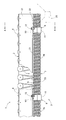
図1,2は、コンベヤ1のフレーム2に取付けられた駆動軸カバー装置3を示している。フレーム2は、そのウェブ21でローラ4の端部を軸受し、コンベヤ1の正面にフランジ22を突出した水平姿勢の軽量形鋼を主体とする。複数のローラ4が並列し、駆動軸5の回転力が伝達部材6を介して個々のローラ4へ伝達される点は、既述の通りである。符号23,24は、フレーム2を図外に設けられたフレームに連結する横枠材、及び駆動軸5を支持するベアリングを各々指している。符号25はコンベヤ1の脚部を指している。
1 and 2 show a drive
駆動軸カバー装置3は、溝形カバー部材7と、掛止部材8と、挟着部材9と、支持部材10と、締結手段11とを備える。駆動軸カバー装置3について以下に詳しく述べる。図面は特に断らない限り、図1乃至図3を参照する。
The drive
駆動軸カバー装置3の要素は図中に1個ずつ表れているが、溝形カバー部材7以外の要素は、互いに矢印S方向に適当な間隔を開けて複数個ずつ配置されているものとする。矢印Sは駆動軸5の軸方向を指している。溝形カバー部材7は、矢印S方向に延びる両側部71,72、及び一方の側部71から下向きに突出する外面73を有するものである。溝形カバー部材7として合成樹脂の成形物を適用するのが好ましい。網目状の孔を有する成形物であれば更に好ましい。両側部71,72の間隔は、その内側に駆動軸5を掛止部材8と共に進入させられる広さがあれば良い。
The elements of the drive
また、溝形カバー部材7は、その断面の形状が溝形のもので自重によって撓まない程度の剛性があれば足りる。例えば、建築用資材として市販されている合成樹脂製のパイプ形の網材を円弧状に分断したものを、溝形カバー部材7として利用しても良い。この場合、溝形カバー部材7を軽量化することができ、溝形カバー部材7の単価を低減して駆動軸カバー装置3の製造コストを削減することができる。しかも、合成樹脂は所望の形状又は寸法になるよう裁断するのが容易であるので、溝形カバー部材7の仕様を、コンベヤ1の設置されている現場で自在に変更できるという利点がある。
The groove-
溝形カバー部材7の外面73には凸条部70が設けられている。即ち、上記パイプ形の網材を更に補強するために、その外周面に合成樹脂製の螺旋管が予め融着されている。この螺旋管が凸条部70に相当する。凸条部70は、溝形カバー部材7の外面73の一部であるが、溝形カバー部材7に必須の要素ではない。凸条部70の有無に関わらず、溝形カバー部材7は上記の剛性を十分満たせるので、溝形カバー部材7に凸条部70を設けた場合、溝形カバー部材7の剛性は一層向上する。また、溝形カバー部材7の網目の大きさ、又は形状は何ら限定されるものではない。
A
掛止部材8は、鋼板を略コ字形に折曲することにより形成されたものであり、スペーサ片81、起立片82、及び傾斜片83を備える。更に、雌ねじ84が起立片82に形成され、鋸刃状の複数の爪85が傾斜片83の下端に形成されている。挟着部材9及び支持部材10は鋼板を略く字形に折曲して成る一体物である。掛止部材8、挟着部材9、及び支持部材10の材質は、鋼に限定されるものではなく、アルミニウム等の軽合金、又は合成樹脂のような非金属であっても良い。
The
挟着部材9は、フレーム2のフランジ22の下面に沿って延びる固定片91、掛止部材8の爪85に溝形カバー部材7の一方の側部71を挟んで対向する挟着片92、及び掛止部材8のスペーサ片81の上方に重なる上部フランジ93を備える。フレーム2のフランジ22を貫く固定ボルト12が、固定片91に穿孔された挿通孔94を通り、固定片91の下側でナット13が固定ボルト12に締付けられている。これにより、挟着部材9及び支持部材10がフレーム2に固定され、駆動軸カバー装置30の全体がフレーム2に位置決めされている。
The
支持部材10は、掛止部材8の爪85が溝形カバー部材7を掛止する位置の下方で、溝形カバー部材7の外面73を支持する役割を果す部位である。締結手段11として、頭部14がコンベヤ1の正面に向けられ、軸部15がコンベヤ1の正面から挟着部材9の挟着片92に穿孔された挿通孔95を貫き、更に軸部15が掛止部材8の雌ねじ84に締付けられるボルトを適用する。この他、掛止部材8を挟着部材9に着脱自在に締付けられるものであれば、バンド、ワイヤ、又はクランプ等を締結手段11として適用しても良い。以下で締結手段11はボルトであるとする。
The
溝形カバー部材7をコンベヤ1から取外すには、先ず作業者がボルト11を緩め、掛止部材8の爪85と挟着部材9の挟着片92との間から溝形カバー部材7の一方の側部71を開放する。この状態で、溝形カバー部材7が両側部71,72の間に位置する重心を力点として他方の側部72が下降する方向へ回転しようとするモーメントを、掛止部材8及び支持部材10の反作用によって打ち消し、掛止部材8と支持部材10との間で溝形カバー部材7の一方の側部71を保持できる。このため、溝形カバー部材7は、コンベヤ1から脱落することがない。
In order to remove the groove-shaped
続いて、作業者が、溝形カバー部材7の他方の側部72を握る等して、一方の側部71を、掛止部材8と挟着部材9との間から引出せば、溝形カバー部材7をコンベヤ1から簡単に取外すことができる。また、作業者は上記のボルト11を緩める工程で、ボルト11の軸部15が掛止部材8の雌ねじ84から離脱するに至るまでボルト11を緩める必要はない。
Subsequently, when the operator pulls out one
反対に、溝形カバー部材7をコンベヤ1に取付けるとき、作業者は溝形カバー部材7を手持ちする等して、一方の側部71を掛止部材8の爪85と挟着部材9の挟着片92との間に挿入する。この時点で、掛止部材8が溝形カバー部材7の一方の側部71を内側から掛止し、この下方の位置で支持部材10が溝形カバー部材7の外面73を支持するので、溝形カバー部材7に発生する上記のモーメントは打ち消される。このため、溝形カバー部材7は、両側部71,72の内側に駆動軸5を進入させた姿勢を維持し、コンベヤ1から脱落することがない。従って、溝形カバー部材7は、コンベヤ1の適所に仮止めされることになる。
On the other hand, when attaching the groove-shaped
続いて、作業者が溝形カバー部材7から手を離しボルト11を締付けるだけで、掛止部材8の爪85と挟着部材9の挟着片92との間に溝形カバー部材7の一方の側部71が強く挟着され、溝形カバー部材7の取付けが完了する。また、掛止部材8の起立片82と挟着部材9の挟着片92との間隔は、掛止部材8のスペーサ片81によって規定される。作業者がボルト11を回転させるとき、掛止部材8がボルト11と共に回転しようとしても、スペーサ片81が挟着部材9の上部フランジ93に突当たるので、掛止部材8が不要に回転することはない。
Subsequently, the operator removes his / her hand from the groove-shaped
以上の述べた駆動軸カバー装置3によれば、ボルト11を締付け及び緩める作業を、作業者はコンベヤ1のフレーム2の正面で行うことができ、しかも、これらの作業を行っている間、作業者は溝形カバー部材7を手持ちする雑作が不要である。従って、溝形カバー部材7のコンベヤ1への取付け、及びコンベヤ1からの取外しの作業が容易である。更に、上記仮止めの段階で溝形カバー部材7の網目状の孔に掛止部材8の爪85を掛けることにより、掛止部材8に対して溝形カバー部材7が滑るのを予防できる。このため、ボルト11が締付けられる過程で、コンベヤ1のフレーム2に対して溝形カバー部材7の位置が狂うことがない。
According to the drive
図4(a),(b)に示すように、溝形カバー部材7の断面は必ずしも円弧状である必要はない。支持部材10を溝形カバー部材7の真下まで延出しても良い。また、掛止部材8を挟着部材9の上部フランジ93に吊下げても良い。この他、溝形カバー部材7は、硬質ゴム、軽合金のサッシバー、パンチングメタル、エキスパンデッドメタル、又は金網から成るものであっても良い。
As shown in FIGS. 4A and 4B, the cross section of the groove-shaped
尚、本発明は、その趣旨を逸脱しない範囲で当業者の知識に基づいて種々なる改良、修正、又は変形を加えた態様で実施できる。図5(a)は、本発明の更なる実施形態に係る駆動軸カバー装置30を示している。これについて上記の実施形態と相違する点を次に説明する。既述の要素には引続き同じ呼称を用いるものとする。 It should be noted that the present invention can be implemented in variously modified, modified, or modified forms based on the knowledge of those skilled in the art without departing from the spirit of the present invention. FIG. 5A shows a drive shaft cover device 30 according to a further embodiment of the present invention. Next, differences from the above embodiment will be described. The same designations will continue to be used for the elements already described.
掛止部材8及び支持部材10は、鋼板を折曲して成る一体物である。掛止部材8は、図2に示した固定ボルト12及びナット13を用いて、フランジ22に固定されている。これにより、挟着部材9がフレーム2に間接的に固定され、駆動軸カバー装置30の全体がフレーム2に位置決めされている。また、挟着部材9は、掛止部材8の爪85に溝形カバー部材7の一方の側部71を挟んで対向する挟着片92、及びスペーサ片96を備える。また、挟着部材9の果す役割をボルト11が担うようにしても良い。この場合、同図(b)に示すように、溝形カバー部材7の一方の側部71に、ボルト11を通すための貫通孔74又は切込部を形成し、ボルト11で直に一方の側部71を掛止部材8に締付ける。
The latching
本発明は、ローラコンベヤの駆動軸に限らず、モータ等で回転する軸と共に動作する部品を覆うのに有益な技術である。 The present invention is not limited to the drive shaft of a roller conveyor, but is a technique useful for covering parts that operate with a shaft that is rotated by a motor or the like.
1:コンベヤ
2:フレーム
3:駆動軸カバー装置
4:ローラ
5:駆動軸
6:伝達部材
7:溝形カバー部材
8:掛止部材
9:挟着部材
10:支持部材
11:締結手段
71,72:側部
73:外面
85:爪
1: Conveyor 2: Frame 3: Drive shaft cover device 4: Roller 5: Drive shaft 6: Transmission member 7: Groove-shaped cover member 8: Holding member 9: Clamping member 10: Support member 11: Fastening means 71, 72 : Side part 73: Outer surface 85: Nail
Claims (4)
前記駆動軸の軸方向に延びる両側部の内側に前記駆動軸を進入させ、外面を下向きに突出した溝形カバー部材と、
前記溝形カバー部材の両側部のうち一方の側部をその内側から掛止する掛止部材と、
前記コンベヤのフレームに固定され、前記掛止部材に前記溝形カバー部材の一方の側部を挟んで対向する挟着部材と、
前記掛止部材が前記溝形カバー部材を掛止する位置の下方で、前記溝形カバー部材の外面を支持する支持部材と、
前記掛止部材を前記挟着部材に着脱自在に締付ける締結手段とを備えることを特徴とする駆動軸カバー装置。 A drive shaft extending along the frame is disposed below a plurality of rollers supported by the frame, and the drive shaft is attached to a conveyor from which rotational force is transmitted to the plurality of rollers via a transmission member. A cover device,
A groove-shaped cover member that allows the drive shaft to enter inside both side portions extending in the axial direction of the drive shaft, and projects the outer surface downward;
A latching member that latches one side of both sides of the groove-shaped cover member from the inside thereof;
A clamping member fixed to the frame of the conveyor and facing the hooking member across one side of the groove-shaped cover member;
A supporting member that supports an outer surface of the groove-shaped cover member below a position where the hooking member latches the groove-shaped cover member;
A drive shaft cover device comprising fastening means for detachably fastening the latch member to the clamping member.
Priority Applications (1)
| Application Number | Priority Date | Filing Date | Title |
|---|---|---|---|
| JP2008121051A JP5024627B2 (en) | 2008-05-07 | 2008-05-07 | Drive shaft cover device |
Applications Claiming Priority (1)
| Application Number | Priority Date | Filing Date | Title |
|---|---|---|---|
| JP2008121051A JP5024627B2 (en) | 2008-05-07 | 2008-05-07 | Drive shaft cover device |
Publications (3)
| Publication Number | Publication Date |
|---|---|
| JP2009269701A JP2009269701A (en) | 2009-11-19 |
| JP2009269701A5 JP2009269701A5 (en) | 2011-10-06 |
| JP5024627B2 true JP5024627B2 (en) | 2012-09-12 |
Family
ID=41436620
Family Applications (1)
| Application Number | Title | Priority Date | Filing Date |
|---|---|---|---|
| JP2008121051A Active JP5024627B2 (en) | 2008-05-07 | 2008-05-07 | Drive shaft cover device |
Country Status (1)
| Country | Link |
|---|---|
| JP (1) | JP5024627B2 (en) |
Cited By (1)
| Publication number | Priority date | Publication date | Assignee | Title |
|---|---|---|---|---|
| TWI686329B (en) | 2017-11-24 | 2020-03-01 | 日商川崎重工業股份有限公司 | Supply device and robot system equipped with the same |
Families Citing this family (2)
| Publication number | Priority date | Publication date | Assignee | Title |
|---|---|---|---|---|
| JP5557478B2 (en) * | 2009-06-03 | 2014-07-23 | オークラ輸送機株式会社 | Roller support and conveying device |
| KR101338907B1 (en) | 2012-06-25 | 2013-12-09 | 주로테크 주식회사 | Apparatus for preventing waste included string reel in a shaft of conveyer system |
Family Cites Families (3)
| Publication number | Priority date | Publication date | Assignee | Title |
|---|---|---|---|---|
| JPH1077724A (en) * | 1996-09-03 | 1998-03-24 | Hiroshi Furukawa | Rain gutter cover |
| JP2000336780A (en) * | 1999-06-02 | 2000-12-05 | Kaoru Taneichi | Throating cover of sill or the like |
| JP4730762B2 (en) * | 2004-08-03 | 2011-07-20 | オークラ輸送機株式会社 | Drive shaft cover device |
-
2008
- 2008-05-07 JP JP2008121051A patent/JP5024627B2/en active Active
Cited By (1)
| Publication number | Priority date | Publication date | Assignee | Title |
|---|---|---|---|---|
| TWI686329B (en) | 2017-11-24 | 2020-03-01 | 日商川崎重工業股份有限公司 | Supply device and robot system equipped with the same |
Also Published As
| Publication number | Publication date |
|---|---|
| JP2009269701A (en) | 2009-11-19 |
Similar Documents
| Publication | Publication Date | Title |
|---|---|---|
| KR101437060B1 (en) | Deck loading system | |
| JP5024627B2 (en) | Drive shaft cover device | |
| KR101456778B1 (en) | Clamp for a pipe | |
| JP5426751B2 (en) | Wiring and piping material support | |
| JP4093560B2 (en) | Parent rope support | |
| JP2007298113A (en) | Long body supporting tool | |
| JP4955639B2 (en) | Exterior material mounting member, its mounting structure, its mounting method, and exterior structure construction method | |
| JP6701190B2 (en) | Tightening device for fixing elongated vehicle parts | |
| JP2009287291A (en) | Concrete form fastening metal piece | |
| JP4321784B1 (en) | Formwork fixture and concrete formwork method | |
| JP2008214980A (en) | Hanger for repair, and repaired roof | |
| JP2013174054A (en) | On-roof fixture | |
| JP2010268733A (en) | Joint | |
| JP2006239851A (en) | Locking device for portable power tool | |
| KR100971183B1 (en) | Fixing clamp for gang form | |
| JP3750942B2 (en) | Temporary fastener for pipe support band | |
| JP5198812B2 (en) | Wiring and piping material support | |
| JP2008274571A (en) | Fixing hardware for folded-plate roofing material | |
| JP5054732B2 (en) | 庇 | |
| JP4788342B2 (en) | Shine back and crime prevention fuence | |
| JP2007327321A (en) | Form structure | |
| JP2008261174A (en) | Temporary fitting for building | |
| JP2019027442A (en) | Fixture and temporary enclosure | |
| JP3159250U (en) | Skirting clamp | |
| KR200488193Y1 (en) | Clamping band |
Legal Events
| Date | Code | Title | Description |
|---|---|---|---|
| A621 | Written request for application examination |
Free format text: JAPANESE INTERMEDIATE CODE: A621 Effective date: 20091217 |
|
| A521 | Request for written amendment filed |
Free format text: JAPANESE INTERMEDIATE CODE: A523 Effective date: 20110824 |
|
| A977 | Report on retrieval |
Free format text: JAPANESE INTERMEDIATE CODE: A971007 Effective date: 20120221 |
|
| TRDD | Decision of grant or rejection written | ||
| A01 | Written decision to grant a patent or to grant a registration (utility model) |
Free format text: JAPANESE INTERMEDIATE CODE: A01 Effective date: 20120524 |
|
| A01 | Written decision to grant a patent or to grant a registration (utility model) |
Free format text: JAPANESE INTERMEDIATE CODE: A01 |
|
| A61 | First payment of annual fees (during grant procedure) |
Free format text: JAPANESE INTERMEDIATE CODE: A61 Effective date: 20120606 |
|
| FPAY | Renewal fee payment (event date is renewal date of database) |
Free format text: PAYMENT UNTIL: 20150629 Year of fee payment: 3 |
|
| R150 | Certificate of patent or registration of utility model |
Free format text: JAPANESE INTERMEDIATE CODE: R150 Ref document number: 5024627 Country of ref document: JP Free format text: JAPANESE INTERMEDIATE CODE: R150 |
|
| R250 | Receipt of annual fees |
Free format text: JAPANESE INTERMEDIATE CODE: R250 |
|
| R250 | Receipt of annual fees |
Free format text: JAPANESE INTERMEDIATE CODE: R250 |
|
| R250 | Receipt of annual fees |
Free format text: JAPANESE INTERMEDIATE CODE: R250 |
|
| R250 | Receipt of annual fees |
Free format text: JAPANESE INTERMEDIATE CODE: R250 |
|
| R250 | Receipt of annual fees |
Free format text: JAPANESE INTERMEDIATE CODE: R250 |
|
| R250 | Receipt of annual fees |
Free format text: JAPANESE INTERMEDIATE CODE: R250 |
|
| R250 | Receipt of annual fees |
Free format text: JAPANESE INTERMEDIATE CODE: R250 |
|
| R250 | Receipt of annual fees |
Free format text: JAPANESE INTERMEDIATE CODE: R250 |
|
| R250 | Receipt of annual fees |
Free format text: JAPANESE INTERMEDIATE CODE: R250 |