JP5022149B2 - Electric power steering device - Google Patents
Electric power steering device Download PDFInfo
- Publication number
- JP5022149B2 JP5022149B2 JP2007227487A JP2007227487A JP5022149B2 JP 5022149 B2 JP5022149 B2 JP 5022149B2 JP 2007227487 A JP2007227487 A JP 2007227487A JP 2007227487 A JP2007227487 A JP 2007227487A JP 5022149 B2 JP5022149 B2 JP 5022149B2
- Authority
- JP
- Japan
- Prior art keywords
- steering
- reaction force
- correction
- control unit
- vehicle behavior
- Prior art date
- Legal status (The legal status is an assumption and is not a legal conclusion. Google has not performed a legal analysis and makes no representation as to the accuracy of the status listed.)
- Expired - Fee Related
Links
Images


Landscapes
- Steering Control In Accordance With Driving Conditions (AREA)
- Power Steering Mechanism (AREA)
Description
本発明は、補助操舵力を発生する電動機の基本制御量を操舵状態に応じて求めると共に、この基本制御量に、車両挙動に応じた補正量を補助操舵力に対する反力成分として付加して操舵力を制御する電動パワーステアリング装置に関するものである。 The present invention obtains a basic control amount of an electric motor that generates an auxiliary steering force according to a steering state, and adds a correction amount according to a vehicle behavior to the basic control amount as a reaction force component with respect to the auxiliary steering force. The present invention relates to an electric power steering device for controlling force.
電動パワーステアリング装置では、運転者の操舵力を軽減する目的で補助操舵力を発生させる電動機が設けられているが、この電動機に発生させる補助操舵力に対する反力成分を、車両の挙動(ヨーレート等)が大きくなるのに応じて増大するように制御するアクティブ反力制御が知られている(例えば特許文献1・2参照)。
In the electric power steering device, an electric motor that generates an auxiliary steering force is provided for the purpose of reducing the driver's steering force. The reaction force component for the auxiliary steering force generated by the electric motor is used as a vehicle behavior (yaw rate, etc.). ) Is known to be controlled so as to increase as the value increases (see, for example,
このアクティブ反力制御によると、車体に横風が当たる場合や、轍のある路面やスプリットμ路面(車両の左右で摩擦係数が異なる路面)を走行する場合に、車両挙動の乱れを抑制する効果を高めて車両の外乱に対する安定性を向上させる外乱抑制効果が得られ、オーバーステア及びアンダーステア等の車両挙動の乱れを収め易くし、ドライバの運転操作負担を低減することができる。
しかるに、このようなアクティブ反力制御では一般的に、反力成分の増大に伴って外乱抑制効果が向上するが、車両挙動に応じた反力成分は、ステアリングホイールを戻す力、すなわちばね成分と同様の働きをし、これを大きくすることは、操舵力のゲインを増大させると共に減衰成分を低下させることから、ドライバの操舵フィールを悪化させる要因となる。このため、車両挙動に応じた反力成分を大きく設定するには限界があり、アクティブ反力制御における外乱抑制効果を十分に高めることができない不都合があった。 However, in such an active reaction force control, the disturbance suppression effect generally improves as the reaction force component increases, but the reaction force component according to the vehicle behavior is a force that returns the steering wheel, that is, a spring component. If the same function is performed and this is increased, the gain of the steering force is increased and the damping component is decreased, which causes a deterioration in the steering feel of the driver. For this reason, there is a limit in setting a large reaction force component according to the vehicle behavior, and there is a disadvantage that the effect of suppressing disturbance in active reaction force control cannot be sufficiently increased.
これに対して、前記の不都合を回避するため、ドライバの手動操舵力に応じて電動機の基本制御量を求めるベース制御の制御パラメータを変更して、基本制御量自体を予め大きく設定しておくことが考えられるが、このようにすると、車両挙動に関する制御系に失陥が発生した場合、例えばヨーレートセンサの故障により車両挙動に応じた補正量の取得が困難になった場合には、操舵反力が軽くなったり、過減衰により粘性感が高くなるなどして、ドライバの操舵フィールの悪化を招いてしまい、結果としてヨーレートセンサが故障しただけにも係わらず、アクティブ反力制御を行わない通常制御時の性能すら確保することができない状態となり、電動パワーステアリング装置全体の信頼性低下を招いてしまうという問題が生じる。 On the other hand, in order to avoid the above inconvenience, the basic control amount itself is set to be large in advance by changing the control parameter of the base control for obtaining the basic control amount of the electric motor according to the manual steering force of the driver. However, if a failure occurs in the control system related to the vehicle behavior, for example, if it becomes difficult to obtain a correction amount according to the vehicle behavior due to a failure of the yaw rate sensor, the steering reaction force Normal control that does not perform active reaction force control even though the yaw rate sensor has failed as a result of the deterioration of the steering feel of the driver due to the fact that the steering wheel feels lighter and the feeling of viscosity increases due to overdamping, etc. Even the performance of the time cannot be ensured, and there arises a problem that the reliability of the entire electric power steering apparatus is reduced.
本発明は、このような発明者の知見に基づき案出されたものであり、その主な目的は、車両の外乱に対する安定性を向上させると共にドライバの操舵フィールを向上させることができるように構成された電動パワーステアリング装置を提供することにある。 The present invention has been devised on the basis of the inventor's knowledge as described above, and its main object is to improve the stability against the disturbance of the vehicle and to improve the steering feel of the driver. An electric power steering apparatus is provided.
このような課題を解決するために、本発明による電動パワーステアリング装置においては、請求項1に示すとおり、補助操舵力を発生する電動機(9)の基本制御量を操舵状態に応じて求めるベース制御部(21)と、このベース制御部とはリレー(26)を介して接続され、補助操舵力に対する反力成分となる補正量を車両挙動に応じて求める車両挙動反力補正部(41)と、前記ベース制御部とはリレー(26)を介して接続され、前記車両挙動反力補正部の補正量に付加される操舵トルクに応じた補正量を求める操舵トルク反力補正部(43)とを有し、前記車両挙動反力補正部の動作を中止する際に、前記リレーをオフとして、前記車両挙動反力補正部の補正量と共に前記操舵トルク反力補正部の補正量に基づく補正が行われないようにしたものとした。
In order to solve such a problem, in the electric power steering apparatus according to the present invention, as shown in
前記の電動パワーステアリング装置においては、請求項2に示すとおり、前記ベース制御部とはリレー(26)を介して接続され、前記車両挙動反力補正部の補正量に付加される操舵速度に応じた補正量を求める操舵速度反力補正部(42)をさらに有する構成とすることができる。また、請求項3に示すとおり、前記ベース制御部を有する第1の制御ユニット(EPS−ECU62・64)と、前記車両挙動反力補正部を有する第2の制御ユニット(車両挙動安定化統合ECU61、VSA用ECU63)とを備え、前記第1の制御ユニットと前記第2の制御ユニットとは、互いに別体で構成されて通信媒体を介して通信可能とした構成とすることができる。また、請求項4に示すとおり、前記第1の制御ユニットは、前記リレー(26)を有する構成とすることができる。
In the electric power steering apparatus, as described in
これによると、ヨーレートなどの車両挙動に応じた補正量に加えて、操舵トルクや操舵速度に応じた補正量で基本制御量が補正されるため、ドライバの操舵フィールを悪化させることなく、車両挙動に応じた補正量を大きく設定して、車両の外乱に対する安定性を向上させることができる。しかも、車両挙動反力補正部の動作を中止する際に、リレーをオフとして、車両挙動に応じた補正量と共に、操舵トルクや操舵速度に応じた補正量に基づく補正が行われないようにする、すなわちベース制御部による基本制御量に基づく通常の制御に復帰させるようにしたため、アクティブ反力制御の失陥時にドライバの操舵フィールが著しく悪化することを避けることができる。 According to this, in addition to the correction amount according to the vehicle behavior such as the yaw rate, the basic control amount is corrected by the correction amount according to the steering torque and the steering speed, so that the vehicle behavior is not deteriorated without deteriorating the steering feel of the driver. Accordingly, the stability against the disturbance of the vehicle can be improved. In addition, when stopping the operation of the vehicle behavior reaction force correction unit, the relay is turned off so that the correction based on the correction amount corresponding to the steering torque and the steering speed is not performed together with the correction amount corresponding to the vehicle behavior. In other words, since the normal control based on the basic control amount by the base control unit is restored, it is possible to avoid the driver's steering feel from being significantly deteriorated when the active reaction force control fails.
車両挙動反力補正部の制御を中止する場合としては、例えば車両挙動反力補正部の失陥、すなわち車両挙動を検出するセンサ(例えばヨーレートセンサ)自体が故障したり、あるいは車両挙動に応じた補正量を車両挙動安定化統合ECU等の外部の制御ユニットで取得する場合にその外部の制御ユニットが故障したために、車両挙動に応じた補正量の取得が正常に行われない事象が発生した場合である。この場合、車両挙動反力補正部の失陥を検知する失陥検知部を設け、この失陥検知部で車両挙動反力補正部の失陥を検知すると、リレーをオフとして信号入力を禁止する構成とすれば良い。 When the control of the vehicle behavior reaction force correction unit is stopped, for example, the failure of the vehicle behavior reaction force correction unit, that is, the sensor (for example, the yaw rate sensor) for detecting the vehicle behavior itself fails, or according to the vehicle behavior. When the correction amount is acquired by an external control unit such as a vehicle behavior stabilization integrated ECU, etc., because the external control unit has failed, and an event occurs in which the correction amount according to the vehicle behavior cannot be acquired normally. It is. In this case, a failure detection unit that detects the failure of the vehicle behavior reaction force correction unit is provided, and when the failure detection unit detects a failure of the vehicle behavior reaction force correction unit, the relay is turned off and signal input is prohibited. What is necessary is just composition.
ここで、操舵トルクは、ドライバが操作子(ステアリングホイール)に加える力であり、操舵トルク反力補正部では、操舵反力中の操舵トルクに依存(比例)する成分に対応する補正量を求める。この操舵トルクに依存する成分は、主に操舵力の大きさを調整するものとなり、例えば操向輪側からラックに入力される外力に関するラックロード成分や、このラックロード成分以外のアシスト成分がこれに該当し、この操舵力調整成分を付加することで、操舵力の大きさを最適化して、ドライバの操舵フィールを向上させることができる。 Here, the steering torque is a force applied by the driver to the operating element (steering wheel), and the steering torque reaction force correction unit obtains a correction amount corresponding to a component that depends (proportional) to the steering torque in the steering reaction force. . The component that depends on the steering torque mainly adjusts the magnitude of the steering force. For example, the rack load component related to the external force input to the rack from the steered wheel side and the assist component other than the rack load component By adding this steering force adjustment component, the magnitude of the steering force can be optimized and the steering feel of the driver can be improved.
また、操舵速度は、ドライバが操作子(ステアリングホイール)を操作する速度(角速度)であり、操舵速度反力補正部では、操舵反力中の操舵速度に依存(比例)する成分に対応する補正量を取得する。この操舵速度に依存する成分は、主に操舵力の減衰成分、すなわち操舵力を減衰させて操作子を重くすると共に操舵力特性を示すリサージュ波形のヒステリシス幅を拡大する成分となるものであり、例えば操舵系のダンパ特性(粘性特性)に関するダンパ成分や、操舵系のフリクション特性(摩擦特性)に関するフリクション成分がこれに該当し、これらの減衰成分を付加して、ばね成分となる車両挙動(ヨーレート)に応じた補正量とのバランスをとることで、減衰過小を改善して、操舵力特性、特にリサージュ波形のヒステリシス幅を最適化して、ドライバの操舵フィールを向上させることができる。 The steering speed is the speed (angular speed) at which the driver operates the operating element (steering wheel), and the steering speed reaction force correction unit corrects the component corresponding to (proportional to) the steering speed during the steering reaction force. Get the quantity. The component that depends on the steering speed is a component that mainly attenuates the steering force, that is, a component that attenuates the steering force and increases the hysteresis width of the Lissajous waveform indicating the steering force characteristic while increasing the operating force. For example, a damper component related to a damper characteristic (viscous characteristic) of a steering system and a friction component related to a friction characteristic (friction characteristic) of a steering system correspond to this. ), It is possible to improve the driver's steering feel by improving the under-attenuation and optimizing the steering force characteristic, particularly the hysteresis width of the Lissajous waveform.
なお、車両挙動反力補正部での補正量取得の基準となる車両挙動は、ヨーレートの他、横加速度なども可能である。 It should be noted that the vehicle behavior as a reference for obtaining the correction amount in the vehicle behavior reaction force correction unit can be a lateral acceleration in addition to the yaw rate.
このように本発明によれば、ヨーレートなどの車両挙動に応じた補正量に加えて、操舵トルクや操舵速度に応じた補正量で基本制御量が補正されるため、ドライバの操舵フィールを悪化させることなく、車両挙動に応じた補正量を大きく設定して、車両の外乱に対する安定性を向上させることができる。しかも、車両挙動反力補正部の動作を中止する際に、リレーをオフとして、ベース制御部による基本制御量に基づく通常の制御に復帰するため、アクティブ反力制御の失陥時にドライバの操舵フィールが著しく悪化することを避けることができる。 As described above, according to the present invention, the basic control amount is corrected by the correction amount according to the steering torque and the steering speed in addition to the correction amount according to the vehicle behavior such as the yaw rate, so that the steering feel of the driver is deteriorated. The correction amount according to the vehicle behavior can be set to a large value and the stability against the disturbance of the vehicle can be improved. Moreover, when the operation of the vehicle behavior reaction force correction unit is stopped, the relay is turned off and the normal control based on the basic control amount by the base control unit is resumed. Can be avoided.
以下、本発明の実施の形態を、図面を参照しながら説明する。 Hereinafter, embodiments of the present invention will be described with reference to the drawings.
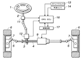
図1は、本発明による電動パワーステアリング装置を示す模式図である。この電動パワーステアリング装置は、ステアリングホイール(操作子)1にステアリングシャフト2を介して一体的に回転可能に連結されたピニオン3と、このピニオン3に噛合して車幅方向に往復動可能に設けられたラック軸4とを有するラック・アンド・ピニオン機構を備え、ラック軸4の両端がタイロッド5を介して操向車輪としての左右の前輪6のナックルアーム7に連結されて、ステアリングホイール1の回転操作に応じて左右の前輪6が転舵されるようになっており、このようなラック・アンド・ピニオン機構を介しての手動操舵力を軽減するための補助操舵力を発生する電動機9がラック軸4に同軸的に設けられている。
FIG. 1 is a schematic diagram showing an electric power steering apparatus according to the present invention. This electric power steering device is provided with a
ステアリングシャフト2には、ステアリングホイール1の操舵角を検出する操舵角センサ11が設けられ、ピニオン3の近傍には、ピニオン3に作用する手動操舵トルクを検出する操舵トルクセンサ12が設けられている。また、車体の適所には、車体に発生するヨーレート(車両挙動)を検出するヨーレートセンサ13と、車速を検出する車速センサ14とが設けられている。
A
これらの操舵角センサ11、操舵トルクセンサ12、ヨーレートセンサ13、及び車速センサ14の各出力信号は、駆動回路17を介して電動機9を制御するステアリング制御装置(EPS-ECU)16に入力されており、このステアリング制御装置16において操舵角、操舵トルク、ヨーレート、及び車速に基づいて電動機9が制御され、所要の補助操舵力がラック軸4に入力される。
The output signals of the
図2は、図1に示したステアリング制御装置16の概略構成を示すブロック図である。このステアリング制御装置16は、各センサからの出力信号に基づいて電動機9の目標電流Itを算出するものであり、目標電流Itの元になるアシスト電流(基本制御量)Iaを操舵状態(ステアリングホイール1に入力される手動操舵力など)に応じて求めるベース制御部21と、アシスト電流Iaに対する補正電流(補正量)Icを車両挙動などに応じて求めるアクティブ反力制御部22と、減算器24とを有している。
FIG. 2 is a block diagram showing a schematic configuration of the
このステアリング制御装置16から出力される目標電流Itは駆動回路17に入力され、この駆動回路17では、電動機9に流れる実電流と目標電流Itとの偏差が小さくなるように電動機9に流れる電流が制御される。
The target current It output from the
ベース制御部21は、ベース電流算出部31と、イナーシャ補償部32と、ダンパ補償部33とを備えている。ベース電流算出部31では、操舵トルクセンサ12による操舵トルク、及び車速センサ14による車速に基づいてベース電流Ibを求める。イナーシャ補償部32は、ステアリング系のイナーシャを補償するものであり、ダンパ補償部33は、ステアリング系のダンピングを補償するものであり、ベース電流Ibに対して所要の補正を行ってアシスト電流Iaを求める。
The
イナーシャ補償部32では、操舵トルクセンサ12による操舵トルクの時間微分値、及び車速センサ14による車速に基づいてイナーシャ補正値を算出して、ベース電流Ibを補正する。ダンパ補償部33では、操舵角センサ11による操舵角を時間微分して得た操舵角速度(モータ角速度)、及び車速センサ14による車速に基づいてダンピング補正値を算出して、ベース電流Ibを補正する。
The
アクティブ反力制御部22は、ヨーレート(車両挙動)に応じた補正電流Iyを求めるヨーレートフィードバック反力補正部(車両挙動反力補正部)41と、ヨーレートフィードバック反力補正部41の補正電流Iyに付加される操舵速度に応じた補正電流を求める操舵速度反力補正部42と、ヨーレートフィードバック反力補正部41の補正電流Iyに付加される操舵トルクに応じた補正電流を求める操舵トルク反力補正部43とを有している。
The active reaction
ヨーレートフィードバック反力補正部41は、ヨーレートに応じて、電動機9に発生させる補助操舵力に対する反力成分、すなわち補助操舵力を減じて操舵反力を増大させる成分となるヨーレート補正電流Iyを算出するものであり、ヨーレートセンサ13の検出値とヨーレート反力補正電流Iyとの相関関係を示すテーブルや計算式に基づいてヨーレート反力補正電流Iyが算出される。
The yaw rate feedback reaction
ここでは、ヨーレートが増大するのに応じてヨーレート反力補正電流Iyが大きくなるように設定されている。このため、ドライバがステアリングホイール1に大きな操舵力を与えても、ヨーレートが大きい場合には、電動機9の補助操舵力が減少して操舵反力が大きくなる、すなわちステアリングホイール1が重くなり、これにより車両の不安定性をドライバに察知させつつ、ドライバのステアリング操作を抑制して、車両の走行安定性を向上させると共にドライバの操舵フィールを向上させることができる。
Here, the yaw rate reaction force correction current Iy is set to increase as the yaw rate increases. Therefore, even if the driver gives a large steering force to the
操舵速度反力補正部42は、操舵反力中の操舵速度に依存(比例)する成分に対応する補正電流を求めるものであり、この操舵速度に依存する成分は、主に操舵力の減衰成分、すなわち操舵力を減衰させてステアリングホイール1を重くすると共に操舵力特性を示すリサージュ波形のヒステリシス幅を拡大する成分となるものであり、この減衰成分を考慮することで、操舵力特性を最適化することができ、ここでは、ダンパ反力補正部44と、フリクション反力補正部45とが設けられており、ここで取得したダンパ補正電流Id及びフリクション補正電流Ifを、ヨーレート補正電流Iyに加算することで、減衰過小を改善して、ドライバの操舵フィールを向上させることができる。
The steering speed reaction
ダンパ反力補正部44は、操舵反力中に占める操舵系のダンパ特性に関するダンパ成分を推定して、これに対応するダンパ補正電流Idを算出するものであり、フリクション反力補正部45は、操舵反力中に占める操舵系のフリクション特性に関するフリクション成分を推定して、これに対応するフリクション補正電流Ifを算出するものである。
The damper reaction
このダンパ成分及びフリクション成分は、主に操舵速度に依存することから、ダンパ補正電流Id及びフリクション補正電流Ifの算出は、第1に操舵角センサ11による操舵角速度に基づいて行われるが、ここでは操舵角速度に加えて、操舵トルクセンサ12による操舵トルクも考量して、ダンパ補正電流Id及びフリクション補正電流Ifが算出される。
Since the damper component and the friction component mainly depend on the steering speed, the calculation of the damper correction current Id and the friction correction current If is first performed based on the steering angular speed by the
操舵トルク反力補正部43は、操舵反力中の操舵トルクに依存(比例)する成分に対応する補正電流を求めるものであり、この操舵トルクに依存する成分は、主に操舵力の大きさを調整するものとなり、この操舵力調整成分を考慮することで、操舵力の大きさを最適化することができ、ここでは、ラックロード反力補正部46と、アシスト反力補正部47とが設けられており、ここで取得したラックロード補正電流Ir及びアシスト補正電流Isを、ヨーレート補正電流Iyから減じることで、操舵反力を軽減して、ドライバの操舵フィールを向上させることができる。
The steering torque reaction
ラックロード反力補正部46は、ラックロード、すなわち旋回などの車両の挙動や轍などの路面状況に応じて車輪6に加わる外力に起因して車輪6側からラック軸4に作用する荷重を推定して、これに対応するラックロード補正電流Irを算出するものであり、アシスト反力補正部47は、ラックロード以外のアシスト成分を推定して、これに対応するアシスト補正電流Isを算出するものである。
The rack load reaction
ラックロード補正電流Irは、操舵トルクセンサ12による操舵トルク、操舵角センサ11による操舵角、及びモータ電流計28により検出される電動機9の実電流に基づいて算出される。またアシスト補正電流Isは、操舵トルクセンサ12による操舵トルクに基づいて算出される。
The rack load correction current Ir is calculated based on the steering torque by the
なお、ラックロードは、ドライバによりステアリングホイール1に入力される手動操舵トルクと、電動機9が出力する補助操舵トルクとを加算し、機械系フリクション要素、すなわち機械的な摩擦による動力損失を減算することで求められる。ここで、手動操舵トルクは、操舵トルクセンサ12により検出されるトルク値にステアリング系慣性項を加算することで求められ、ステアリング系慣性項は、操舵角センサ11により検出される操舵角を2階微分して得られる操舵角加速度から求められる。補助操舵トルクは、モータ電流計28による電動機9の実電流から求められる。機械系フリクション要素は、定数で与えれば良い。
In the rack load, the manual steering torque input to the
また、ダンパ反力補正部44、フリクション反力補正部45、ラックロード反力補正部46、及びアシスト反力補正部47では、各センサの検出値、あるいはその微分値などの計算値と補正電流Id・If・Ir・Isとの相関関係を示すテーブルや計算式に基づいて補正電流Id・If・Ir・Isが算出され、このテーブルや計算式は、実験値や設計値に基づいて予め作成しておく。
In addition, the damper reaction
このようにしてアクティブ反力制御部22において、ヨーレート補正電流Iy、ダンパ補正電流Id、フリクション補正電流If、ラックロード補正電流Ir、及びアシスト補正電流Isが求められ、これらの補正電流が加算器51及び減算器52〜54に入力されて、最終的な補正電流Icが算出され、これを式で表すと、
Ic=Iy+(Id+If)−Ir−Is
となる。
In this way, the active reaction
Ic = Iy + (Id + If) -Ir-Is
It becomes.
さらにこのアクティブ反力制御部22で取得した補正電流Icは減算器24に入力され、ここで、ベース制御部21で取得したアシスト電流Iaから補正電流Icが減算されて目標電流Itが算出され、これを式で表すと、
It=Ia−Ic=Ia−(Iy+Id+If)+(Ir+Is)
となる。
Further, the correction current Ic acquired by the active reaction
It = Ia−Ic = Ia− (Iy + Id + If) + (Ir + Is)
It becomes.
さらにこのステアリング制御装置16は、アクティブ反力制御部22からの補正電流Icの信号の減算器24に対する入力を断続するリレー26と、アクティブ反力制御部22の失陥を検知する失陥検知部27とを備えており、失陥検知部27からのリレー駆動信号によりリレー26がオン/オフ(導通/遮断)制御される。
Further, the
失陥検知部27では、アクティブ反力制御部22の失陥、すなわちヨーレートセンサ13の故障などによりヨーレートフィードバック反力補正部41での補正電流Iyの算出処理が実行不能か否かが判定され、アクティブ反力制御部22の失陥がない正常時にはリレー26がオンとなり、アクティブ反力制御部22からの補正電流Icの信号が減算器24に入力される。
In the
他方、アクティブ反力制御部22の失陥が発生すると、リレー26がオフとなり、アクティブ反力制御部22からの補正電流Icの信号が減算器24に入力されず、ダンパ補償部33からのアシスト電流Iaが補正されることなく駆動回路17に入力される。これにより、アクティブ反力制御部22の失陥が発生した場合には、ベース制御部21のみによる通常の制御に復帰し、ドライバの操舵フィールが著しく悪化することをを避けることができる。
On the other hand, when the failure of the active reaction
図3は、本発明による電動パワーステアリング装置におけるスラローム操舵時の操舵力特性(リサージュ波形)の一例を示すグラフであり、ステアリングホイール1の回転操作に応じた操舵角の変化に伴う操舵トルクの変動状況を示している。ここでは、車速V=140km/h、操舵周波数(操舵周期の逆数)f=1.0Hzとしている。 FIG. 3 is a graph showing an example of a steering force characteristic (Lissajous waveform) at the time of slalom steering in the electric power steering apparatus according to the present invention. Indicates the situation. Here, the vehicle speed V = 140 km / h and the steering frequency (reciprocal of the steering cycle) f = 1.0 Hz.
単純にヨーレートフィードバック反力補正部41によるヨーレートフィードバック成分のみを加えた場合には、ベース制御部21による場合と比較して、矢印で示すように操舵力特性が変化し、具体的には操舵トルクのゲイン増大によりステアリングホイール1が重くなり、また減衰低下によりヒステリシス幅が減少してステアリングホイール1のふらつきが発生して、操舵フィールが悪化してしまう。これは、ヨーレートフィードバック成分が、減衰成分や操舵力調整成分を有していないことに起因する。
When only the yaw rate feedback component by the yaw rate feedback reaction
これに対して、図2に示したように、減衰成分(ダンパ成分及びフリクション成分)、及び操舵力調整成分(ラックロード成分及びアシスト成分)をヨーレートフィードバック成分と共に加えるようにすると、操舵トルクのゲイン低減によりステアリングホイール1を軽くし、またヒステリシス幅を拡大してステアリングホイール1のふらつきを抑制して、良好な操舵フィールを実現することができる。
On the other hand, if a damping component (damper component and friction component) and a steering force adjustment component (rack load component and assist component) are added together with the yaw rate feedback component as shown in FIG. The
図4は、本発明によるステアリング制御装置の別の例を示すブロック図である。前記の例ではステアリング制御装置(EPS-ECU)16に、電動機9のアシスト電流(基本制御量)を操舵状態に応じて求めるベース制御部21と共に、アシスト電流に対する補正電流を車両挙動等に応じて求めるアクティブ反力制御部22を一体的に設けたが、ここでは、ベース制御部を有するEPS−ECUとは別の制御ユニットにアクティブ反力制御部が設けられ、このアクティブ反力制御部で取得した補正電流が、適宜な通信媒体を介して、EPS−ECUに送られるようになっている。
FIG. 4 is a block diagram showing another example of the steering control device according to the present invention. In the above example, the steering control device (EPS-ECU) 16 is supplied with the
図4(A)に示す例では、LKAS(Lane Keep Assist System、車線維持支援システム)などで採用される車両挙動安定化統合ECU61内にアクティブ反力制御部22が設けられ、このアクティブ反力制御部22で取得した補正電流が、CAN(Controller Area Network)やFlex−Rayなどのネットワークを介して、EPS−ECU62に送られるようになっている。図4(B)に示す例では、他デバイス用ECU、例えばVSA(Vehicle Stability Assist、車両挙動安定化制御システム)のECU63にアクティブ反力制御部22が設けられ、このアクティブ反力制御部22で取得した補正電流が、シリアル通信線などを介して、EPS−ECU64に送られるようになっている。
In the example shown in FIG. 4 (A), an active reaction
一方、EPS−ECU62・64には、ベース制御部21と共に、受信した補正電流の信号が減算器24に入力することを許可・禁止するリレー26が設けられており、ヨーレートセンサの故障の他に、アクティブ反力制御部22が設けられた車両挙動安定化統合ECU61や他デバイス用ECU63の故障・失陥により、アクティブ反力制御部22で補正電流の取得が正常に行われない、あるいはアクティブ反力制御部22で取得した補正電流の送信が正常に行われない事象が発生した場合には、リレー26がオフとなり、ベース制御部21のみによる制御が行われ、失陥時の操舵フィールの著しい悪化を回避することができる。
On the other hand, the EPS-
なお、前記の例では、アクティブ反力制御部22に操舵速度反力補正部42と操舵トルク反力補正部43とを共に設けたが、そのいずれか一方としても良い。さらに前記の例では、操舵速度反力補正部42にダンパ反力補正部44とフリクション反力補正部45とを共に設けたが、そのいずれか一方としても良い。また前記の例では、操舵トルク反力補正部43にラックロード反力補正部46とアシスト反力補正部47とを共に設けたが、そのいずれか一方としても良い。
In the above example, the active reaction
1 ステアリングホイール
6 車輪
9 電動機
11 操舵角センサ
12 操舵トルクセンサ
13 ヨーレートセンサ
16 ステアリング制御装置
21 ベース制御部
22 アクティブ反力制御部
24 減算器
26 リレー
27 失陥検知部
41 ヨーレートフィードバック反力補正部(車両挙動反力補正部)
42 操舵速度反力補正部
43 操舵トルク反力補正部
44 ダンパ反力補正部
45 フリクション反力補正部
46 ラックロード反力補正部
47 アシスト反力補正部
51 加算器
52〜54 減算器
DESCRIPTION OF
42 Steering speed reaction
Claims (4)
このベース制御部とはリレーを介して接続され、補助操舵力に対する反力成分となる補正量を車両挙動に応じて求める車両挙動反力補正部と、
前記ベース制御部とはリレーを介して接続され、前記車両挙動反力補正部の補正量に付加される操舵トルクに応じた補正量を求める操舵トルク反力補正部とを有し、
前記車両挙動反力補正部の動作を中止する際に、前記リレーをオフとして、前記車両挙動反力補正部の補正量と共に前記操舵トルク反力補正部の補正量に基づく補正が行われないようにしたことを特徴とする電動パワーステアリング装置。 A base control unit for obtaining a basic control amount of an electric motor that generates an auxiliary steering force according to a steering state;
A vehicle behavior reaction force correction unit that is connected to the base control unit via a relay and obtains a correction amount that becomes a reaction force component for the auxiliary steering force according to the vehicle behavior;
A steering torque reaction force correction unit that is connected to the base control unit via a relay and calculates a correction amount according to a steering torque added to the correction amount of the vehicle behavior reaction force correction unit;
When stopping the operation of the vehicle behavior reaction force correction unit, the relay is turned off so that the correction based on the correction amount of the steering torque reaction force correction unit together with the correction amount of the vehicle behavior reaction force correction unit is not performed. An electric power steering device characterized by that.
前記車両挙動反力補正部を有する第2の制御ユニットとを備え、
前記第1の制御ユニットと前記第2の制御ユニットとは、互いに別体で構成されて通信媒体を介して通信可能としたことを特徴とする請求項1または請求項2に記載の電動パワーステアリング装置。 A first control unit having the base control unit;
A second control unit having the vehicle behavior reaction force correction unit,
3. The electric power steering according to claim 1, wherein the first control unit and the second control unit are configured separately from each other and can communicate with each other via a communication medium. apparatus.
Priority Applications (1)
| Application Number | Priority Date | Filing Date | Title |
|---|---|---|---|
| JP2007227487A JP5022149B2 (en) | 2007-09-03 | 2007-09-03 | Electric power steering device |
Applications Claiming Priority (1)
| Application Number | Priority Date | Filing Date | Title |
|---|---|---|---|
| JP2007227487A JP5022149B2 (en) | 2007-09-03 | 2007-09-03 | Electric power steering device |
Publications (2)
| Publication Number | Publication Date |
|---|---|
| JP2009056994A JP2009056994A (en) | 2009-03-19 |
| JP5022149B2 true JP5022149B2 (en) | 2012-09-12 |
Family
ID=40553126
Family Applications (1)
| Application Number | Title | Priority Date | Filing Date |
|---|---|---|---|
| JP2007227487A Expired - Fee Related JP5022149B2 (en) | 2007-09-03 | 2007-09-03 | Electric power steering device |
Country Status (1)
| Country | Link |
|---|---|
| JP (1) | JP5022149B2 (en) |
Families Citing this family (5)
| Publication number | Priority date | Publication date | Assignee | Title |
|---|---|---|---|---|
| JP5591837B2 (en) | 2012-01-25 | 2014-09-17 | 本田技研工業株式会社 | Vehicle and steering device |
| JP5900309B2 (en) * | 2012-12-15 | 2016-04-06 | マツダ株式会社 | Lane maintenance support device |
| KR102087144B1 (en) * | 2013-11-26 | 2020-03-10 | 현대모비스 주식회사 | Apparatus for driving of motor drive power steering and method thereof |
| KR102207573B1 (en) * | 2014-11-28 | 2021-01-27 | 현대모비스 주식회사 | Apparatus for compensating disturbance of mdps system |
| JP6844393B2 (en) * | 2017-04-13 | 2021-03-17 | トヨタ自動車株式会社 | Driving support control system |
Family Cites Families (4)
| Publication number | Priority date | Publication date | Assignee | Title |
|---|---|---|---|---|
| JP3110891B2 (en) * | 1992-09-16 | 2000-11-20 | 本田技研工業株式会社 | Vehicle steering system |
| JP3103052B2 (en) * | 1997-11-18 | 2000-10-23 | 本田技研工業株式会社 | Vehicle steering system |
| JPH11208492A (en) * | 1998-01-20 | 1999-08-03 | Honda Motor Co Ltd | Control method for electric power steering device |
| JP4226169B2 (en) * | 1999-11-09 | 2009-02-18 | 本田技研工業株式会社 | Vehicle steering system |
-
2007
- 2007-09-03 JP JP2007227487A patent/JP5022149B2/en not_active Expired - Fee Related
Also Published As
| Publication number | Publication date |
|---|---|
| JP2009056994A (en) | 2009-03-19 |
Similar Documents
| Publication | Publication Date | Title |
|---|---|---|
| JP5320292B2 (en) | Electric power steering device | |
| JP5971426B2 (en) | Electric power steering device | |
| US7983816B2 (en) | Control apparatus for electric power steering apparatus | |
| JP5327331B2 (en) | Electric power steering device for vehicle | |
| EP1803627B1 (en) | Electric power steering apparatus | |
| JP4293021B2 (en) | Vehicle steering system | |
| CN107867286B (en) | Vehicle control device and vehicle control method | |
| JP5943018B2 (en) | Steering control device | |
| JP4728406B2 (en) | Electric power steering device | |
| JP5313729B2 (en) | Electric power steering device | |
| JP5061768B2 (en) | Vehicle steering system | |
| WO2018055805A1 (en) | Control device for power steering device | |
| US9701338B2 (en) | Electric power steering apparatus | |
| JP2007125944A (en) | Control device for electric power steering device | |
| US9796411B2 (en) | Electric power steering apparatus | |
| JP5022149B2 (en) | Electric power steering device | |
| JP4997478B2 (en) | Vehicle steering system | |
| JP4517810B2 (en) | Vehicle steering control device | |
| JP4956782B2 (en) | Vehicle steering control device | |
| JP2005082119A (en) | Electric power steering device | |
| JP5144093B2 (en) | Electric power steering device | |
| JP2007269062A (en) | Steering device of vehicle | |
| JP4814905B2 (en) | Vehicle steering control device | |
| JP2006069497A (en) | Steering device | |
| JP2006168481A (en) | Vehicle steering controller and steered angle control method |
Legal Events
| Date | Code | Title | Description |
|---|---|---|---|
| A621 | Written request for application examination |
Free format text: JAPANESE INTERMEDIATE CODE: A621 Effective date: 20091127 |
|
| RD02 | Notification of acceptance of power of attorney |
Free format text: JAPANESE INTERMEDIATE CODE: A7422 Effective date: 20110911 |
|
| A977 | Report on retrieval |
Free format text: JAPANESE INTERMEDIATE CODE: A971007 Effective date: 20111128 |
|
| A131 | Notification of reasons for refusal |
Free format text: JAPANESE INTERMEDIATE CODE: A131 Effective date: 20111206 |
|
| A521 | Written amendment |
Free format text: JAPANESE INTERMEDIATE CODE: A523 Effective date: 20120203 |
|
| A131 | Notification of reasons for refusal |
Free format text: JAPANESE INTERMEDIATE CODE: A131 Effective date: 20120306 |
|
| A521 | Written amendment |
Free format text: JAPANESE INTERMEDIATE CODE: A523 Effective date: 20120501 |
|
| TRDD | Decision of grant or rejection written | ||
| A01 | Written decision to grant a patent or to grant a registration (utility model) |
Free format text: JAPANESE INTERMEDIATE CODE: A01 Effective date: 20120522 |
|
| A01 | Written decision to grant a patent or to grant a registration (utility model) |
Free format text: JAPANESE INTERMEDIATE CODE: A01 |
|
| A61 | First payment of annual fees (during grant procedure) |
Free format text: JAPANESE INTERMEDIATE CODE: A61 Effective date: 20120615 |
|
| R150 | Certificate of patent or registration of utility model |
Ref document number: 5022149 Country of ref document: JP Free format text: JAPANESE INTERMEDIATE CODE: R150 Free format text: JAPANESE INTERMEDIATE CODE: R150 |
|
| FPAY | Renewal fee payment (event date is renewal date of database) |
Free format text: PAYMENT UNTIL: 20150622 Year of fee payment: 3 |
|
| LAPS | Cancellation because of no payment of annual fees |